cs8 device tester - spirent · the information contained in this document is subject to change...
TRANSCRIPT

CS8 Device Tester Reference Test Packs
User Manual

Spirent 541 Industrial Way West Eatontown, NJ 07724 USA
Email: [email protected] Web: http://www.spirent.com
AMERICAS 1-800-SPIRENT • +1-818-676-2683 • [email protected] EUROPE AND THE MIDDLE EAST +44 (0) 1293 767979 • [email protected] ASIA AND THE PACIFIC +86-10-8518-2539 • [email protected]
This manual applies to CS8 Device Tester Version 1.20 or higher.
Page Part Number: 71-006837, Version A0
Copyright © 2012 Spirent. All Rights Reserved.
All of the company names and/or brand names and/or product names referred to in this document, in particular, the name “Spirent” and its logo device, are either registered trademarks or trademarks of Spirent plc and its subsidiaries, pending registration in accordance with relevant national laws. All other registered trademarks or trademarks are the property of their respective owners.
The information contained in this document is subject to change without notice and does not represent a commitment on the part of Spirent. The information in this document is believed to be accurate and reliable; however, Spirent assumes no responsibility or liability for any errors or inaccuracies that may appear in the document.

Table of Contents
1. Introduction .......................................................................................... 1
1.1. Overview ........................................................................................... 1
1.2. Intended Audience ............................................................................. 1
1.3. Before You Get Started ....................................................................... 1
1.4. Security Information .......................................................................... 1
1.5. Accessing Documentation .................................................................. 3
1.5.1. Accessing Documentation from Windows Explorer ................................... 3
1.5.2. Accessing Documentation from Test Manager ......................................... 3
2. Test Pack Description ............................................................................ 5
2.1. Overview ........................................................................................... 5
2.2. Description ........................................................................................ 5
3. Using the Test Packs ............................................................................. 6
3.1. Overview ........................................................................................... 6
3.2. Configuring the Platform Parameters .................................................. 6
3.2.1. Supported Platforms ............................................................................... 6
3.2.2. 8100-B Series Platform Parameters ........................................................ 6
3.3. Configuring the UE Parameters ........................................................... 7
3.3.1. UE Interface Parameters .......................................................................... 7
3.3.2. UE Manual Interface Parameters ............................................................. 8
3.3.3. UE AT Interface Parameters ..................................................................... 9
3.3.4. Spirent Data Client Parameters ............................................................. 12
3.3.5. UE Capability Parameters ....................................................................... 13
3.4. Configuring the Session Parameters ................................................. 15
3.4.1. Session Control Parameters ................................................................... 15
3.5. Selecting the Parameter Files for Session Execution .......................... 16
4. Locating the Test Suites and Test Cases .............................................. 17
4.1. Locating Pre-defined Test Packs ....................................................... 17
4.2. Creating a Custom Test Suite ............................................................ 17
4.3. Running a Test Suite ........................................................................ 19

ii | CS8 Device Tester – Reference Test Pack: User Manual
5. Setting Up a New UE with Data Client .................................................. 22
5.1. Overview ......................................................................................... 22
5.2. UE as Dial-Up Modem ....................................................................... 22
5.3. UE as Network Interface Card (NIC) ................................................... 24
5.4. UE as Internet Connection Sharing (ICS) Device ................................. 25
5.4.1. Using the Wi-Fi Interface ....................................................................... 25
5.4.2. Using a USB-based NIC Interface .......................................................... 26
5.5. Configuring the AT Interface in a UE File ............................................ 27

1. Introduction
1.1. Overview
This document provides information on the CS8 Reference Test Packs. You will become familiar with the Test Pack Suites, Test Cases, and setting up testing scenarios in the Test Manager environment by following the step-by-step procedures and Test Reference documentation.
1.2. Intended Audience
This manual is intended for those who have a working knowledge of wireless communication equipment, and are familiar with the automated testing of mobile devices. It is assumed that the audience is familiar with the Test Manager GUI environment. Those who are unfamiliar with the Test Manager should refer to the Test Manager User Manual, before proceeding further.
1.3. Before You Get Started
Before getting started with this guide, install all software and power up the test system. The controller PC is shipped with the Test Manager Test Executive software and CS8 Reference Test Packs installed.
1.4. Security Information
The CS8 Reference Test Packs are shipped with the appropriate dongle and software/hardware security passwords configured.
To verify the security information:
1. Open Test Manager and select Help>About. The About Test Manager window displays.
2. Confirm CS8 Development Library UI is installed under the Test Folders tab, as shown in Figure 1-1.

2 | CS8 Device Tester – Reference Test Pack: User Manual
Figure 1-1: About Test Manager Window
3. Select the Passwords tab.
4. Under Installed Features, confirm the features for related CS8 RTP and MDTTM-TS-UDL-TWO are installed, as shown in Figure 1-2.
Figure 1-2: About Test Manager Window – Installed Features
Password authentication is a prerequisite for running any tests supported by these test packs. This password is tied to security information provided by the USB hard-lock dongle that comes with the module installation.
NOTE: Passwords are also required for the following installed modules: • CS8 Interactive Tester • AirAccessWCDMA-HS • SR5500M
If you have any questions or concerns, contact Spirent Technical Support at support.spirent.com, or by phone at 1-800-SPIRENT.

Chapter One: Introduction | 3
1.5. Accessing Documentation
There are two ways to access CS8 documents from the Controller PC:
1. Windows Explorer
2. Test Manager
1.5.1. Accessing Documentation from Windows Explorer
Access all CS8 Reference Test Pack manuals offline by navigating to C:\Program Files\Spirent Communications\Test Manager\Suites\CS8 Reference Test Sets in Windows Explorer, as shown in Figure 1-3.
Figure 1-3: Accessing the Manual from Windows Explorer
1.5.2. Accessing Documentation from Test Manager
Access the CS8 manuals from the Test Manager menu by selecting: Help>Test Folders>CS8 Development Library UI>User Manual.pdf, as shown in Figure 1-4.

4 | CS8 Device Tester – Reference Test Pack: User Manual
Figure 1-4: Accessing the Manual from Test Manager

2. Test Pack Description
2.1. Overview
This chapter provides a high-level overview of the key software and hardware components necessary to configure and use the CS8 Reference Test Packs.
2.2. Description
All CS8 Reference Test Packs are integrated software components that allow you to perform interactive and automated testing on a UE device.
Support is provided for:
• LTE Bands: 1, 2, 3, 4, 5, 7, 10, 12, 13, 14, 17, 20, 24, 25 and 26.
• LTE Bandwidth: 1.4, 3, 5, 10, 15 and 20.
NOTE: 1.4M, 3M, 15M and 20MHz bandwidths and Band Classes 1, 2, 3, 5, 12, 20, 24, 25, and 26 have not been fully validated.

3. Using the Test Packs
3.1. Overview
This chapter gives information on using CS8 Reference Test Packs from Test Manager.
This includes the following steps:
1. Configuring the Platform Parameters
2. Configuring the UE Parameters
3. Configuring the Session Parameters
4. Selecting the Parameter Files for Session Execution
5. Locating the Test Cases
6. Creating a Custom Test Suite
7. Configuring Test Case parameters
8. Running a Test Suite
9. Setting up a New UE with the Data Client
3.2. Configuring the Platform Parameters
3.2.1. Supported Platforms
The CS8 Reference Test Packs support the following platforms:
• 8100-B Series
3.2.2. 8100-B Series Platform Parameters
The parameters for the 8100-B Series platform configure the technologies present in the system, as shown in Figure 3-1. For example, set the E2010S Enabled parameter to “True” to support LTE, and set Network Configuration to “2 – eNodeB” to configure dual cell LTE.

Chapter Three: Using the Test Packs | 7
Figure 3-1: Test Manager Platform File
3.3. Configuring the UE Parameters
The level of automation and reliability of the system is heavily dependent on the ability of the system to control the UE. UE parameters are configured to facilitate these activities.
3.3.1. UE Interface Parameters
The UE interface parameters specify how the UE is controlled during test case execution. The options for the UE Control Method are:
• Manual: The system prompts the operator to perform actions on the UE.
• AT: The system issues the specified AT commands to control the UE.
• Custom: (Advanced) Allows custom UE control. If Custom is selected, the UE Control Sequence File parameter specifies the Control Sequence file used by the system.
The ability of the system to return the UE to a known state before execution of a test case is important. If the UE supports a reliable reset command, set the Reset for Ensure Idle parameter to “True”.

8 | CS8 Device Tester – Reference Test Pack: User Manual
Figure 3-2: UE Parameters Window – UE Interface Parameters
NOTE: In cases where the UE Control Method is set to anything other than Manual, the Manual method will be attempted as a fall-back if a command fails or is not provided.
3.3.2. UE Manual Interface Parameters
If the UE Control Method parameter under the UE Interface tab is set to “Manual”, if a command fails, or is not provided by the selected UE Control Method, the parameters of the UE Manual Interface are used. In this case, a window displays prompting you to perform the necessary action on the UE.
• Timeout Parameters: Specifies how long the system waits before automatically selecting the defined Timeout Button. The timeout value is selected from a drop-down box providing a range from "Disabled" to "Indefinite." A value of "Disabled" indicates no user prompt will be displayed and testing will proceed as if the UE control was completed successfully. A value of “Indefinite” indicates the function will wait indefinitely. Note that even if Manual control is not selected, it may be used in case of failure. If the timeout value is set to “Indefinite”, the system will wait indefinitely, which may not be desirable.
• Timeout Button Parameters: If a timeout other than "Disabled" or "Indefinite" is specified, these parameters specify if the OK or Cancel button is selected when the timeout expires.

Chapter Three: Using the Test Packs | 9
Figure 3-3: UE Parameters Window – UE Manual Interface Parameters
Configuring these parameters correctly can be effective in allowing some level of automation; even if AT commands are not available or supported for the UE under Test.
For example, if the UE can be configured to auto-answer an incoming call, you can set the timeout for Answer Voice Call. This allows the UE time to auto-answer the call, and the Timeout Button for Answer Voice Call can be set to OK. This configuration allows the device to reliably answer network-initiated voice calls.
3.3.3. UE AT Interface Parameters
If the UE reliably supports AT commands, AT control can be very useful. The UE is connected to the Data Client PC for AT control after the manufacturer's driver software is installed.
The following parameters are provided, as shown in Figure 3-4:
• Client IP Address: Set this parameter to the IP address of the Data Client PC. NOTE: The default address 192.168.0.61 should not be changed.
• Primary COM Port Settings/Secondary COM Port Settings: These parameters configure the standard serial port parameters. Two COM ports can be used if the UE has separate COM ports for control. For example, if there is a separate USB device to control the USB connection to the UE for automated power-cycling.

10 | CS8 Device Tester – Reference Test Pack: User Manual
NOTE: The CS8 RTP do not support using the Secondary COM Port.
• Port: Set this parameter to the port on the Data Client PC assigned to the modem when the UE is connected.
• Bits per Second: Configure the baud rate.
• Data Bits: Configure the number of data bits.
• Parity: Configure the parity.
• Stop Bits: Configure the stop bits.
• Flow Control: Configure the flow control.
• Enable DTR: Enables Data Terminal Ready Signaling.
• Enable RTS: Enables Request To Send Signaling.
• New Line: Specifies the new line terminator to use.
• Commands: Configure the available AT command strings.
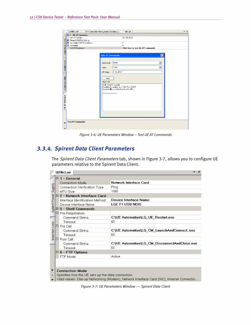
• Test AT Commands: Use this wizard to test AT commands to check if the UE responds correctly and reliably before testing.
Figure 3-4: UE Parameters Window —UE AT Interface Port Parameters

Chapter Three: Using the Test Packs | 11
Figure 3-5: Parameters Window – UE AT Interface AT Command Parameters
NOTE 1: There is great variability in the AT commands supported by UE vendors and how reliably they work. Experimentation may be necessary to determine the best settings. NOTE 2: For proper execution of AT commands during test run, we recommend that you do not have the default HTTP proxy set in ControlPanel>InternetOptions on the Controller PC. Before execution, make sure the Client IP Address is set to 192.168.0.61. This is required for triggering AT commands successfully on the Client PC.
12 | CS8 Device Tester – Reference Test Pack: User Manual
Figure 3-6: UE Parameters Window – Test UE AT Commands
3.3.4. Spirent Data Client Parameters
The Spirent Data Client Parameters tab, shown in Figure 3-7, allows you to configure UE parameters relative to the Spirent Data Client.
Figure 3-7: UE Parameters Window -— Spirent Data Client

Chapter Three: Using the Test Packs | 13
The following parameters are provided:
• Connection Mode: Specifies how the UE sets up the data connection. There are currently four modes supported: Dial-up Networking, Network Interface Card, Internet Connection Sharing, and Wi-Fi.
• Connection Verification Type: Specifies how to verify the establishment of the connection when the connection mode is Network Interface Card, Internet Connection Sharing, and Wi-Fi.
• MTU Size: Specifies the MTU Size of the UE under test in bytes.
• Interface Identification Method: Specifies the method the Spirent Data Client uses to identify the UE Network Interface on the Client Laptop.
• Device Interface Name: Specifies the device interface name in the route table. This name can be obtained by typing "route print" in the Command Prompt on the Client Laptop when the UE is connected.
NOTE: The Device Interface Name has to be exactly the same as indicated on the client laptop, including any spaces.
• Shell Commands: Specifies certain shell commands if an AT command is not used. These shell commands can be executed on the Client Laptop before registration, before setting up data call and after ending a data call. If the shell command is empty, nothing will be executed.
• FTP Options: Specifies how the Spirent Data Client initiates the FTP data connection.
3.3.5. UE Capability Parameters
UE Capability parameters configure the security and authentication settings for the UE as shown in Figure 3-8.These parameters also include configuring the PDN number and properties, as shown in Figure 3-9.
The following parameters are provided for security and authentication settings:
• AS Security: AS Security settings
• NAS Security: NAS Security settings
• NAS Authentication: NAS Authentication settings
• HSS Settings: HSS Settings

14 | CS8 Device Tester – Reference Test Pack: User Manual
Figure 3-8: UE Parameters Window –Security and Authentication Parameters
The following parameters are provided for configuring PDN number and PDN properties:
• PDNs: Parameters for supported PDNs.
• PDN [N]: Specifies valid PDN settings.
• IP Address Type: Specifies the type of IP address the UE will request. Valid Values: IPv4, IPv6,IPv4v6.
• APN: Specifies the Access Point Name (APN) the UE will communicate with.
• Services: Parameters for mapping services to PDNs.
• Service [N]: Parameters for mapping the service to the PDN.
• Service: Specifies the service. Valid Values: Administrative, Application, IMS, and Internet.
• PDN: Specifies the PDN that carries this service.

Chapter Three: Using the Test Packs | 15
Figure 3-9: UE Parameters Window – UE Capability Parameters for PDN
3.4. Configuring the Session Parameters
3.4.1. Session Control Parameters
Session Parameters control the execution of the session as shown in Figure 3-10.
Rerunning Test Cases: These parameters control the automatic rerunning of test cases that end with a final result of “Incomplete” or “Failed”.
Rerunning Test Case Iterations: These parameters control the behavior of iteration-based test cases.
NOTE: Because CS8 Reference Test Packs are not iteration-based; these parameters are not used.
Reset UE between Test Cases: Resetting the UE between test cases can improve system performance and stability in some cases.
NOTE: The CS8 Reference Test Packs automatically reset the UE at various points during the test; it is not necessary to set this parameter to “True”.

16 | CS8 Device Tester – Reference Test Pack: User Manual
Figure 3-10: Session Parameters
3.5. Selecting the Parameter Files for Session Execution
As indicated in the Test Manager User Manual, you cannot run a suite successfully unless it undergoes validation using the specified Platform, Session, and UE Parameter files.
In the Execute Session window, select the Session File, UE File, and Platform File. Select the Platform type, as shown in Figure 3-11.
Figure 3-11: Selecting Parameter Files – LTE Module

4. Locating the Test Suites and Test Cases
4.1. Locating Pre-defined Test Packs
1. From Test Manager, in the File Cabinet under the Suite Files tab, select Suites>CS8 Reference Test Sets, as shown in Figure 4-1.
Figure 4-1: Locating Pre-defined Test Packs
4.2. Creating a Custom Test Suite
You can create a custom test suite from a blank CS8 Development Library UI template and add steps. To quickly build a test, we recommend that you copy-and-paste from a pre-defined CS8 Reference Test that is closest to what you need.
To create a test suite:
1. From the Test Manager menu, select File>New>Suite File, as shown in Figure 4-2. You can also use the toolbar shortcuts available to create a new file, as shown in Figure 4-3.

18 | CS8 Device Tester – Reference Test Pack: User Manual
Figure 4-2: Creating a New Suite
Figure 4-3: Creating a Suite File using the Toolbar Shortcut
2. A new Test Suite window displays.
3. Open a pre-defined test pack from File Cabinet. Select the desired test, press Ctrl-C, or right-click and select Copy from the menu.

Chapter Four: Locating the Test Suites and Test Cases | 19
Figure 4-4: Copying a Test Case from a pre-define Test Suite
4. Switch to the new suite by clicking the Suite File tab. Press Ctrl-V or right-click and select Paste from the menu.
Figure 4-5: Pasting a Test Case into a Suite
5. Configure the parameters for each test case based on your testing needs. Refer to the Test Pack User Manual for additional information on configuring Test Case Parameters.
6. When you have completed adding and sequencing the test cases, save the suite file. The custom suite file displays in the File Cabinet.
4.3. Running a Test Suite
After creating the custom test suite and configuring the test case parameters, or selecting a pre-defined test suite, you must ensure the suite passes validation.
As discussed in the Test Manager User Manual, the key requirements to run a user-defined suite are a valid Session, UE, and Platform file.
To run the test suite:
1. In the Test Manager File Cabinet, under the Suite Files tab, open the desired test suite, as shown in Figure 4-6.

20 | CS8 Device Tester – Reference Test Pack: User Manual
Figure 4-6: Loading a CS8 Reference Test Pack
2. In the Test Manager menu, select Execute>Start Session>Run All Test Cases to start executing the entire Test Suite. You also have the option of executing only the currently selected test case. The Execute Session window displays.
3. Select the appropriate parameter files and platform. For more information on selecting these files, refer to Chapter 5.
4. If desired, specify the Tester Name, UE Manufacturer, and UE Model. These fields display on all reports you create based on the results of this session.
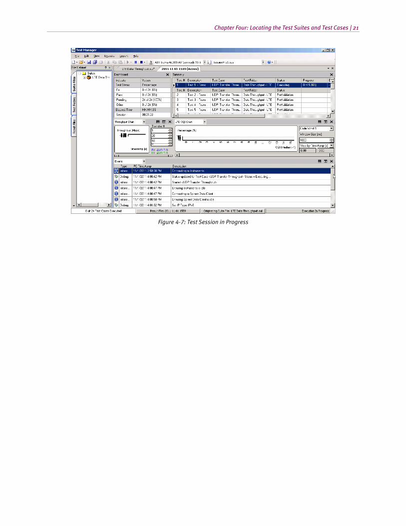
5. Click OK to begin validation. If successful, the test session begins, as shown in Figure 4-7.
Chapter Four: Locating the Test Suites and Test Cases | 21
Figure 4-7: Test Session in Progress
5. Setting Up a New UE with Data Client
5.1. Overview
To introduce or setup a new UE (or swap between more than one) connected to the Data Client PC, you need to configure the system to establish data connectivity from the Controller PC, as well as the Application Server. While both the Data Client and the Application Server are connected by the Ethernet cable, the data transfer throughput must occur through the Network Emulator interface.
There are three types of UEs depending on how they interface with the Data Client laptop. Traditional UMTS devices often act as dial-up modems while LTE data cards often act as Network Interface Cards (NICs), the same as an Ethernet adapter. The third type that is becoming popular among smart phones is called “Tethering”, “Hot Spot” in Android devices, or “Internet Connection Sharing” in Windows-based mobile devices. Some UEs support multiple modes.
Regardless of the UE type, it may support AT commands that allow greater automation. This chapter contains detailed instructions on how to set up the UE.
5.2. UE as Dial-Up Modem
1. On the Data Client laptop, install the manufacturer software/drivers for the new UE. The UE software should support an installation configurable as a tethered modem.
NOTE: The Data Client laptop has a modem dial-up connection named TestDrive Data Connection configured for use with your UE. This is part of the installation and cannot be changed.
2. The Data Client laptop is pre-configured to support Client Dial-up connections for the tethered modem-configured UE under Test. Use the TestDrive Data Connection Dial-up networking setting on the laptop to set up the UE.
3. On the Data Client laptop, select Control Panel>Network Connections, right-click TestDrive Data Connection and select Properties from the menu, as shown in Figure 5-1.

Chapter Five: Setting Up a New UE | 23
Figure 5-1: Data Client Network Connections
Figure 5-2: TestDrive Data Connections Properties Window – Selecting Current UE
4. Under the General tab, shown in Figure 5-3, select the correct UE from the Test in the Connect Using list.
5. Refer to the UE specifications and enter the correct dial-in number. By default, the Data Client laptop is set to a dial-in number of *99#. Note that *99# is one of two AT Command GPRS specifications for a request to use the Packet Domain service. The other common dial-in number is *98#.
6. In the UE file, select Dial-up Networking as the Connection Mode.

24 | CS8 Device Tester – Reference Test Pack: User Manual
Figure 5-3: Dial-up Networking as Connection Mode
7. Follow the instructions given in Section 5.5 to set up AT commands in UE file for automation.
5.3. UE as Network Interface Card (NIC)
1. On the Data Client laptop, install the manufacturer software/drivers for the new UE. Make sure the UE displays in Device Manager as one of the Network Adapters, as shown in Figure 5-4.
Figure 5-4: UE as Network Adapter
2. Take a note of the name of the adapter to enter it in the UE file as the Device Interface Name.
3. In Test Manager, create a new UE file. Under the Spirent Data Client tab, select Network Interface Card as Connection Mode, Device Interface Name as Interface Identification Method, and enter the exact adapter name for the Device Interface Name.

Chapter Five: Setting Up a New UE | 25
Figure 5-5: UE File Spirent Data Client Parameters
4. Follow the instructions in Section 5.5 to set up AT commands in UE file for automation.
5.4. UE as Internet Connection Sharing (ICS) Device
A UE working as an ICS device acts like a gateway or router to the Data Client laptop. For example, it would assign an internal IP address such as 192.168.100.10 to the laptop while it obtains an external IP address such as 192.168.9.1 from the network. It performs NAT (Network Address Translation) for any packet in and out of the device. In order for some tests, such as downlink UDP to work, the UE file needs to be properly configured so the system can "prime" the UE by sending an uplink UDP packet. This allows a dynamic NAT entry to register in the UE.
The connection between the UE and the laptop can be a USB-based NIC interface, often called “Tethering”, or a Wi-Fi connection, usually called “Hot Spot”.
5.4.1. Using the Wi-Fi Interface
1. Power on the UE and follow the UE instructions to enable Wi-Fi service (Hot Spot).
2. On the Data Client laptop, enable Wi-Fi interface. Follow UE instructions to search and connect to the UE Hot Spot.
3. Take a note of the Wi-Fi interface name in Device Manager.
26 | CS8 Device Tester – Reference Test Pack: User Manual
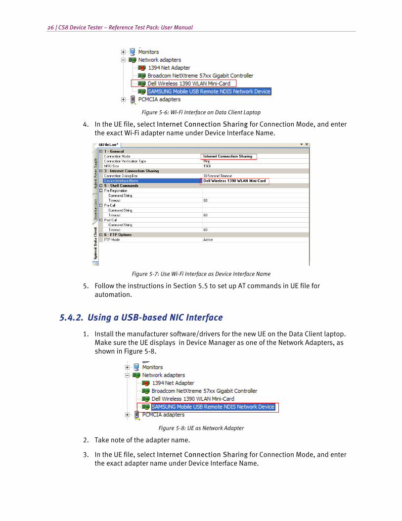
Figure 5-6: Wi-Fi Interface on Data Client Laptop
4. In the UE file, select Internet Connection Sharing for Connection Mode, and enter the exact Wi-Fi adapter name under Device Interface Name.
Figure 5-7: Use Wi-Fi Interface as Device Interface Name
5. Follow the instructions in Section 5.5 to set up AT commands in UE file for automation.
5.4.2. Using a USB-based NIC Interface
1. Install the manufacturer software/drivers for the new UE on the Data Client laptop. Make sure the UE displays in Device Manager as one of the Network Adapters, as shown in Figure 5-8.
Figure 5-8: UE as Network Adapter
2. Take note of the adapter name.
3. In the UE file, select Internet Connection Sharing for Connection Mode, and enter the exact adapter name under Device Interface Name.

Chapter Five: Setting Up a New UE | 27
Figure 5-9: USB-based NIC Interface
4. Follow the instructions in Section 5.5 to set up AT commands in UE file for automation.
5.5. Configuring the AT Interface in a UE File
At commands allow greater automation in running test cases. If the UE being tested supports AT commands, you must set up the device to enable test case automation. The instructions below provide information on identifying and verifying the COM port for the AT interface, as well as how to configure and test the AT interface in the UE file.
1. On Data Client laptop, open Device Manager and find the COM port number of the AT interface. It can be found under Ports (COM & LPT), or Modems, as shown in Figure 5-10.
Figure 5-10: AT Interface in Ports or Modems

28 | CS8 Device Tester – Reference Test Pack: User Manual
2. If the COM port number displays under Ports (COM & LPT), take note of the port number. If it displays under the modems, right-click the modem and select Properties from the menu, as shown in Figure 5-11.
Figure 5-11: Modem Properties
3. Under the Modem tab, take note of the COM port number, as shown in Figure 5-12.
Figure 5-12: Modem COM Port Number
4. Test the AT interface by opening a HyperTerminal window or any other serial communication tool. Connect to the AT interface COM port, baud rate 115200, data bits 8, no parity, 1 stop bit and no flow control. Type "AT" and make sure the UE responds with "OK", as shown in Figure 5-13.

Chapter Five: Setting Up a New UE | 29
Figure 5-13: Testing the AT Interface
5. Close the window.
6. Open the UE file in Test Manager. Under the UE AT Interface tab, enter the correct COM port number and other communication parameters, as shown in Figure 5-14. Refer to the UE manuals and enter the correct AT commands supported by the UE.
Figure 5-14: UE AT Interface Parameters
7. Next to the last parameter in UE AT Interface Parameters window, click the … button, as shown in Figure 5-15.

30 | CS8 Device Tester – Reference Test Pack: User Manual
Figure 5-15: Testing AT Commands
8. Select the AT command to test and click the Test button. The Test AT Commands window displays, as shown in Figure 5-16
Figure 5-16: Test AT Commands Window
9. After all commands are verified, close the window and save the UE file. You are now ready to run all tests with this UE file.
NOTE: The AT COM port number and adapter name may change if you plug your UE to a different USB port. Always check and update the UE file before running any test.