cs-series high-speed data storage unit (spu unit) cs1w
TRANSCRIPT

CSM_CS1W-SPU01-V2/02-V2_DS_E_5_1
1
CS-series High-speed Data Storage Unit (SPU Unit)
CS1W-SPU01-V2/02-V2High-speed Collection of System Data
The CPU Unit can collect large amounts of process data, operation data, inspection data, and other controlled system data quickly and automatically save the data in external storage media as CSV files.
Features• There is no need to write ladder programming to collect data. Even with an existing system, just mount an SPU Unit and add it to the I/O tables
to start data collection.• The total size of variables that can be specified to collect data is 7,776 words.• Use specified times or events as triggers to record the contents of specified words in I/O memory in the CPU Unit.• In Data Storage Mode, up to 65 data collection patterns are possible with one basic collection pattern and data collection patterns 1 to 64.
Combine the collection patterns with events to simultaneously collect many different types of data.• Collected data can be stored in PC cards or in a computer connected via Ethernet. Data Management Middleware can be used to make a few
simple settings to store the data in a host computer.• Recipes can be used to batch-write numeric or text string data, such as production parameters, in the memory areas of the CPU Unit. Recipe
data can be saved in a Memory Card in the SPU Unit to easily enable process switchovers.• SPU Units with a unit version of 2.1 or later also provide an FTP client. This enables sending files of collected data to an FTP server on a host
computer, eliminating the need to write programming to store data in the host computer.
System Configuration
CS1W-SPU02-V2
LAN straight cable
(commercially available)
Hub or other network device
SPU Unit CPU Unit
LAN straight cable (commercially available)
SPU-Console Setting/Monitoring Software
Windows is a registered trademark of Microsoft Corporation in the United States and other countries.Other company names and product names in this document are the trademarks or registered trademarks of their respective companies.

2
CS1W-SPU01-V2/02-V2
Ordering InformationInternational Standards• The standards are abbreviated as follows: U: UL, U1: UL (Class I Division 2 Products for Hazardous Locations), C: CSA, UC: cULus, UC1: cULus (Class I Division
2 Products for Hazardous Locations), CU: cUL, N: NK, L: Lloyd, and CE: EC Directives.• Contact your OMRON representative for further details and applicable conditions for these standards.
SPU Unit (High-speed Data Storage Unit)
Support Software
Option
Industrial Switching Hubs
Unit type Productname
SpecificationsNo. of unit
numbersallocated
Currentconsumption
(A) Model Standards
PC Card slot Ethernet (LAN) port 5V 26V
CS1 CPUBus Unit
SPU Unit(High-speedData StorageUnit) 1 PC Card Type II slot Insert an
OMRON HMC-EF@@@to use the Memory Card.
1 port(10/100BASE-TX)
1
0.56 — CS1W-SPU01-V2
UC1, CE
2 ports(10/100BASE-TX) 0.70 — CS1W-SPU02-V2
Product name Specifications Model Standards
SPU-Console Support Software
Functions: Unit settings, sampling settings, etc., for High-speed Data Collection Units(required for making settings for this Unit)
OS : Windows 2000, XP, or VistaWS02-SPTC1-V2 —
Product name Specifications Model Standards
SPU DataManagementMiddleware
Function: Data files collected by SPU Data ManagementMiddleware are automatically acquired at the personalcomputer, and can be registered in a database.OS :Windows 2000, XP, or Vista
1 license WS02-EDMC1-V2
—
5 licenses WS02-EDMC1-V2L05
Memory Cards
Flash memory, 128MB Note:Memory Cardis required fordata collection.
HMC-EF183
N, L, CEFlash memory, 256MB HMC-EF283
Flash memory, 512MB HMC-EF583
Memory Card Adapter (for a computer's PCMCIA slot) HMC-AP001 CE
Product name Appearance
SpecificationsCurrent
consumption (A) Model StandardsFunctions No. of
pors
Failuredetec-tion
Industrial Switching Hubs
Quality of Service (QoS): EtherNet/IP control data priorityFailure detection: Broadcast storm and LSI error detection10/100BASE-TX, Auto-Negotiation
3 No 0.08 W4S1-03B
UC, CE
5 No 0.12 W4S1-05B
5 Yes 0.12 W4S1-05C CE

CS1W-SPU01-V2/02-V2
3
Accessories
Mountable Racks
* The number of Units that can be mounted depends on the power supply capacity. C200HW-PA204@: 4 Units max.C200HW-PA209R: 10 Units max.
Model Accessories Specifications
CS1W-SPU01-V2CS1W-SPU02-V2 PF-IN connector (premounted) Connector for uninterruptible power supply PF-IN connection: MC1.5/2-STF-
3.81, manufactured by Phoenix Contact
Model
CS1 System CS1D System
CPU RackExpansion Backplane
(including LongdistanceExpansion Rack)
SYSBUSRemote
I/O SlaveRack
C200HX/HG/HE
ExpansionI/O Rack
CPU Rack ExpansionBackplane
CS1W-BC CS1W-BI CS1D-BC CS1D-BI
@@3 @@2 @@3 @@2 052 042D 082S 092 082D
CS1W-SPU01-V2CS1W-SPU02-V2 16 Units (per CPU Unit) ∗ Not
supportedNot supported
16 Units (per CPU Unit) ∗

4
CS1W-SPU01-V2/02-V2
Functional and Performance Specifications
* Use the HMC-EF@@@ Memory Card from OMRON. Normal operation may not be possible with any other compact flash cards.
General Specifications: Specifications conform to the general specifications of the CS-series CPU Units.
Item Specifications
Unit model number CS1W-SPU01/02-V2
Applicable CPU Units CS Series
Unit classification CPU Bus Unit
Unit number 0 to F
Mounting location CPU Backplane or CS-series Expansion Backplane (Cannot be mounted to C200H Expansion I/O Rack or SYSMAC BUS Remote I/O Slave Rack.)
No. of Units per PLC 16 Unit max.
Interfaces
PC card slot PC card Type II, 1 slot (Conforms to PC Card Standard Release 8.0.)Used by mounting Memory Card and HMC-AP001 Memory Card Adapter. ∗
COMM port For future expansion
Ethernet (LAN) ports CS1W-SPU01-V2: One port (10/100Base-TX, RJ45 Modular Connector)CS1W-SPU02-V2: Two ports (10/100Base-TX, RJ45 Modular Connectors)
UPS power failure input 24 VDC (+10%/-15%) inputConnect the power failure signal output line from the UPS.
Settings and operation
Unit number switch (UNIT) Rotary switch: Sets the unit number of the Unit as a CPU Bus Unit.
Select switch (SELECT) Toggle switch: Sets the number of the command to execute.
Enter button (ENTER) Pushbutton switch: Confirms and starts execution of the command number set using the select switch.
DIP switch (DIPSW) DIP switch: System settings
Card button Pressed to release the Memory Card inserted in the PC card slot. The Memory Card can then be removed.
Indications
LED indicators RUN, ERC, ERH, COMM, LAN1, LAN2, CARD, and PF-IN
7-segment display
• Displays error information and operating status of the SPU Unit.• Displays the command number set on the select switch. • Displays the IP address.• Display other information.
Functions
• Sampling• Saving files• Network communications• Recipe function
Operating modes Data Storage Mode and Sampling Mode (Either mode can be selected with the Change Operating Mode command.)
Current consumption
CS1W-SPU01-V2:5 VDC, 560 mA max. (SPU Unit only)Other: Memory Card (HMC-EF@@@): 120 mA max.(Supplied from Power Supply Unit.)
CS1W-SPU02-V2:5 VDC, 700 mA max. (SPU Unit only)Other: Memory Card (HMC-EF@@@): 120 mA max.(Supplied from Power Supply Unit.)
Dimensions CS1W-SPU01/SPU02-V2:35 × 130 × 101 mm (W × H × D)
Weight
CS1W-SPU01-V2:280 g max. (including enclosed connector)
CS1W-SPU02-V2:290 g max. (including enclosed connector)

CS1W-SPU01-V2/02-V2
5
Detailed Specifications
Item Specifications
Sampling
Sampling Mode
Sampling patternsRealtime sampling: 1 patternNormal sampling : Up to 3 patterns
Starting methods
Any one of the following methods can be used:• Start automatically when SPU Unit is started.• Start with an SPU-Console operation.• Start with the SPU Unit’s front-panel command buttons.
(Specify the command number.) • Start from the CPU Unit’s ladder program.
IntervalUser-specified intervals: ∗1
Realtime sampling: 5 ms min.Normal sampling : 100 ms min.
Data Storage Mode(Unit Ver. 1.2 or later)
Data Collection Patterns
Basic Collection Pattern : 1 pattern (required)Data Collection Patterns : Up to 64 patterns
Starting methods
Basic Collection Pattern (required)
Any one of the following methods can be used:• Start when a specified event occurs. (Use a memory event
or scheduled event. For details, see the description of Data Collection Patterns 1 to 64 below.)
• Start automatically when SPU Unit is started.• Start with an SPU-Console operation.• Start with the SPU Unit’s front-panel command buttons.
(Specify the command number.) • Start from the CPU Unit’s ladder program.
Data Collection Patterns 1 to 64
Either of the following methods can be used to start when an event occurs:• Memory events:
Start when a CPU Unit bit or word value matches a spec-ified condition. Up to 500 memory events can be specified.
• Scheduled events:Start at a specified time or time interval. Up to 16 sched-uled events can be specified.
IntervalUser-specified intervals: ∗2 ∗3
Basic Collection Pattern: 5 ms min.Data Collection Patterns: 100 ms min.
Data Storage Mode(Unit Ver. 2.0 or later) Copy option Basic Collection Pattern: Cannot be set.
Data Collection Patterns: Up to 10 patterns.
Shared Sampling Mode and Data Storage Mode settings
Applicable CPU Unit I/O memory areas
CIO Area, WR Area, HR Area, AR Area, DM Area, and EM Area banks 0 to C
Specifying I/O memory areas
Specify the desired CPU Unit I/O memory area (data area) with a variable.The data type can be specified with the variable. The variables can be managed in groups.
Variable data types
BOOL, INT, UINT, DINT, UDINT, REAL, LREAL, STRING, CHANNEL, UINT BCD, UDINT BCD, WORD, DWORD, CHANNEL BLOCK
Maximum number of variables 7,776 words total for all variables
Record Condition setting
Set whether or not to use a record condition.If a record condition is used, sampling data is stored within the SPU Unit only when the record condition is met. For example, sampling data can be recorded only while a specified bit is ON or a specified word contains a particular value (comparison).
Data exchange with the CPU Unit
CPU Bus Unit Area• CPU Unit to SPU Unit: Command execution (such as starting/stopping sam-
pling, clearing a sampling file, or saving a sampling file).• SPU Unit to CPU Unit: SPU Unit status information
Saving files
Collected data file format
CSV files Indices (record number), time stamps (hh:mm:ss:ms), ns, sampling indices (serial numbers starting at 0 when sam-pling is started), data for each symbol delimited with com-ma, records delimited with carriage returns
Record contents
Number of sampling result records stored in one file
Any one of the following methods can be used.• The number of records can be specified.• A time period can be specified. (The number of records is calculated automat-
ically from the time period and interval between samples.)• With a version 1.2 or later SPU Unit, the number of records can be left unspec-
ified. (In this case, data is added to the file until data collection is stopped. Records are added to one file from the start of data collection until the end.)
ScalingInstead of directly storing the values collected from the CPU Unit’s I/O memory, the collected values can be scaled with a linear equation or upper/lower limit range before storage (unit version 1.2 or later).
File size 2 GB per file
Record size Specified by user.
Number of records Specified by user or calculated automatically.
Saving method Data can be saved to a single file or multiple files (up to 1,200 files).
Network communicationsWindows network shared folders
Files in the Memory Card inserted in the PC card slot in the SPU Unit can be shared with a Windows 2000/XP/Vista personal computer.
FTP FTP server/client provided.
Network communications FINS communications
• FINS server to execute FINS command• Routing to transfer FINS messages

CS1W-SPU01-V2/02-V2
6
s
Recipe function Data Storage Mode (Unit Ver. 2.0 or later)
Number of fields 10,000
Recipe filesFile format: CSVThe file size is restricted by the size of file that can be stored in the recipe folder. Records : Specified by the user.
Number of records
No limit, but restricted by the file size that can be stored in the recipe folder.
Writing methodConversion method: Each field is written to the specified address in the specified data type. Continuous region method: Data written to continuos memory addresses.
Searching for recipe keys
Searching within files: The text string that was passed as the key is searched for in the target search columns in the recipe files and the rows for any matches that are found are extracted as recipe data.Searching for file names: The text string that was passed as the key is searched for in the recipe file names (i.e., a search is made for key.csv), and the files with matching files names are used as recipe files just like previous versions.Key list search: A search is made for recipe keys with the method used for unit version 2.0.
*1. In both cases, the sampling cannot be performed faster than the CPU Unit’s cycle time. The actual sampling interval will always be longer than the CPU Unit’s cycle time even if the sampling interval is set shorter than the cycle time.
*2. The Data Collection Patterns use the data collected by the Basic Collection Pattern, so the data will be collected at the Basic Collection Pattern’s interval even if the Data Collection Pattern’s interval is set shorter than the Basic Collection Pattern’s interval.
*3. The actual Basic Collection Pattern interval will always be longer than the CPU Unit’s cycle time even if the sampling interval is set shorter than the cycle time.
Note: For details, refer to "CS1W-SPU01/SPU02-V2, CJ1W-SPU01-V2 SPU Units Operation Manual"(Cat. No. V236).
Item Specifications
CS1W-SPU01-V2/02-V2
7
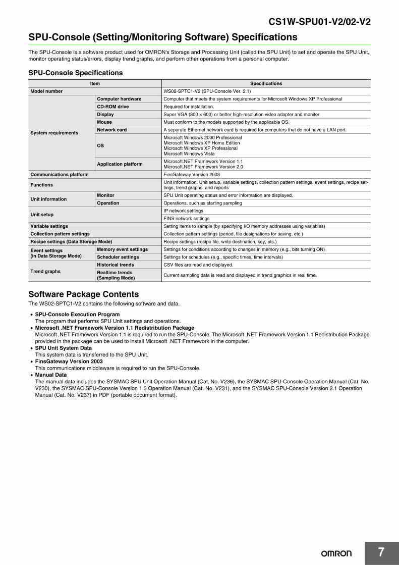
SPU-Console (Setting/Monitoring Software) SpecificationsThe SPU-Console is a software product used for OMRON's Storage and Processing Unit (called the SPU Unit) to set and operate the SPU Unit, monitor operating status/errors, display trend graphs, and perform other operations from a personal computer.
SPU-Console Specifications
Software Package ContentsThe WS02-SPTC1-V2 contains the following software and data.
• SPU-Console Execution ProgramThe program that performs SPU Unit settings and operations.
• Microsoft .NET Framework Version 1.1 Redistribution PackageMicrosoft .NET Framework Version 1.1 is required to run the SPU-Console. The Microsoft .NET Framework Version 1.1 Redistribution Package provided in the package can be used to install Microsoft .NET Framework in the computer.
• SPU Unit System DataThis system data is transferred to the SPU Unit.
• FinsGateway Version 2003This communications middleware is required to run the SPU-Console.
• Manual DataThe manual data includes the SYSMAC SPU Unit Operation Manual (Cat. No. V236), the SYSMAC SPU-Console Operation Manual (Cat. No. V230), the SYSMAC SPU-Console Version 1.3 Operation Manual (Cat. No. V231), and the SYSMAC SPU-Console Version 2.1 Operation Manual (Cat. No. V237) in PDF (portable document format).
Item Specifications
Model number WS02-SPTC1-V2 (SPU-Console Ver. 2.1)
System requirements
Computer hardware Computer that meets the system requirements for Microsoft Windows XP Professional
CD-ROM drive Required for installation.
Display Super VGA (800 × 600) or better high-resolution video adapter and monitor
Mouse Must conform to the models supported by the applicable OS.
Network card A separate Ethernet network card is required for computers that do not have a LAN port.
OS
Microsoft Windows 2000 ProfessionalMicrosoft Windows XP Home EditionMicrosoft Windows XP ProfessionalMicrosoft Windows Vista
Application platform Microsoft.NET Framework Version 1.1Microsoft.NET Framework Version 2.0
Communications platform FinsGateway Version 2003
Functions Unit information, Unit setup, variable settings, collection pattern settings, event settings, recipe set-tings, trend graphs, and reports
Unit informationMonitor SPU Unit operating status and error information are displayed.
Operation Operations, such as starting sampling
Unit setupIP network settings
FINS network settings
Variable settings Setting items to sample (by specifying I/O memory addresses using variables)
Collection pattern settings Collection pattern settings (period, file designations for saving, etc.)
Recipe settings (Data Storage Mode) Recipe settings (recipe file, write destination, key, etc.)
Event settings(in Data Storage Mode)
Memory event settings Settings for conditions according to changes in memory (e.g., bits turning ON)
Scheduler settings Settings for schedules (e.g., specific times, time intervals)
Trend graphsHistorical trends CSV files are read and displayed.
Realtime trends(Sampling Mode) Current sampling data is read and displayed in trend graphics in real time.

8
CS1W-SPU01-V2/02-V2
SPU Data Management Middleware (EDMS)The SPU Data Management Middleware (hereafter the EDMS) is software that reads CSV-format files from an SPU Unit and copies the files to a specified folder on a computer hard disk over an Ethernet network.With version 2.0 or higher, the collected data can be stored in a database.
EDMS StructureThe EDMS consists of the following programs.
• Copy Task ServiceThe Copy Task Service copies files from an SPU Unit and saves them to a computer hard disk on the same network. The service operates in the background and is used to monitor SPU Units.
• Database Storage ServiceThe Database Storage Service stores the files that are copied to the computer into a database. The service operates in the background.
• EDMS-ConsoleThe EDMS-Console is a user-interface program that provides access to the setting windows. It accesses the Copy Setting Window, for example, to allow the user to input Copy Task Service settings, specify operations, and monitor operating conditions. The program displays the files that have been copied to the computer in a list that can be used for data management.The Database Storage Windows enable setting the database storage service, controlling the storage operation, and monitoring operating status.
EDMS SpecificationsItem Description
Model WS02-EDMC1-V2
System requirements
Processor Intel Pentium, Celeron, or compatible processor
CD-ROM drive Required for installation
Display Super VGA (800 × 600) or better high-resolution video adaptor and monitor
Mouse Mouse supported by the applicable OS.
Network card Computers without a LAN port require an Ethernet network card (sold separately).
Compute r
Collected data
SPU Unit CPU Unit
Database Storage Function The collected data can be stored in a database either at the press of a bu tton or in the ba ck ground after sta rt ing the computer .
Co py Function The collected data can be copied to the computer either at the press of a bu tton or in the ba ck ground after star ting the compute r.
SPU DataManagement Middle wa re (EDMS)
DB
Ethernet
CSV files Sampling
Copy Setting Window Copy Task Service
EDMS
FinsGateway Service EDMS-Console
Database Storage Setting Window Database Storage Service
Microsoft NET Framework1.1
Microsoft Windows 2000 / XP / Vista

CS1W-SPU01-V2/02-V2
9
Software Package ContentsThe WS02-EDMC1-V2 software package contains the following items.
• EDMS Installation ProgramThe EDMS installation program is used to install the Copy Task Service and EDMS-Console on a computer.
• Microsoft .NET Framework Version 1.1 Redistributable PackageMicrosoft .NET Framework Version 1.1 is required to run the SPU-Console. The Redistributable Package provided in the software package can be used to install .NET Framework on the computer.
• FinsGateway Version 2003The FinsGateway version 2003 communications middleware is required to run the SPU-Console.
• Operation ManualThe SPU Data Management Middleware User’s Manual (Cat. No. V232) is included in PDF format in the software package.
System requirementsOS
Microsoft Windows 8 (32bit/64bit)Microsoft Windows 7 (32bit/64bit)Microsoft Windows VistaMicrosoft Windows XP ProfessionalMicrosoft Windows XP Home EditionMicrosoft Windows Server 2012Microsoft Windows Server 2008Microsoft Windows Server 2003
Application platform (execution environment)
Microsoft .NET Framework version 1.1Microsoft Data Access Component 2.6 or later
Communications platform FinsGateway version 2003
Other software requirements SPU-Console (sold separately) required to input SPU Unit settings.
Registration of applicable SPU Units SPU Units can be registered by specifying the IP address and name of the Unit (same for the SPU-Console).
Copy function
Copies files from the Memory Card in a registered SPU Unit to a specified folder on a computer hard disk. The function is enabled only when two or more is set in the Number of files Field from the SPU-Console.
Settable number of copies 256 max.
Copy start conditions Start Button or automatically on computer startup.
Copy timingFiles will be saved to the computer hard disk over the network automatically when copying is enabled (data collection has stopped or files have been transferred).
Storage location Any specified folder
Saved file name
File names can be created automatically using one or any combination of the following objects: Any text string, the name of the copy, the name of the source SPU Unit, the time or date (month, day, year) the file was copied, consecutive file numbers, the date or time of the start record, and the date or time of the last record.
Copy monitoring cycle Settable cycle for monitoring when copying is enabled. Default: 10 s
Status indicators Used to check starting, started (monitoring copying), copying, stopped, and error status conditions.
Log displayPress the Display of log Button to display the operating status or an error log list that shows the month/day/year, time, event ID, and description.
Database storage function
Data files that are copied to a specified folder on a computer hard disk are stored in a database. The function is enabled only when three or more is set in the Number of files Field from the SPU-Console.
Settable number of data base storage services 65 max.
Database storage start conditions Start Button or automatically on computer startup.
Storage timing Files will be automatically stored in the database as soon as storable files are detected.
Applicable databasesMicrosoft Access 2000, 2002, 2003Microsoft SQL Server 2000, 2005Oracle Database 10g2
Copy folder monitoring cycleSettable cycle for monitoring when there are storable files. Default: 10 s
Status indicators Used to check whether storage is in progress (monitor-ing for storable files) or stopped.
Log displayPress the Display of log Button to display the operating status or an error log list that shows the month/day/year, time, and description.
SPU clock synchronization function The SPU Unit (version 1.2 or later only) and CPU Unit clocks are periodically synchronized with the computer clock.
Item Description
10
CS1W-SPU01-V2/02-V2
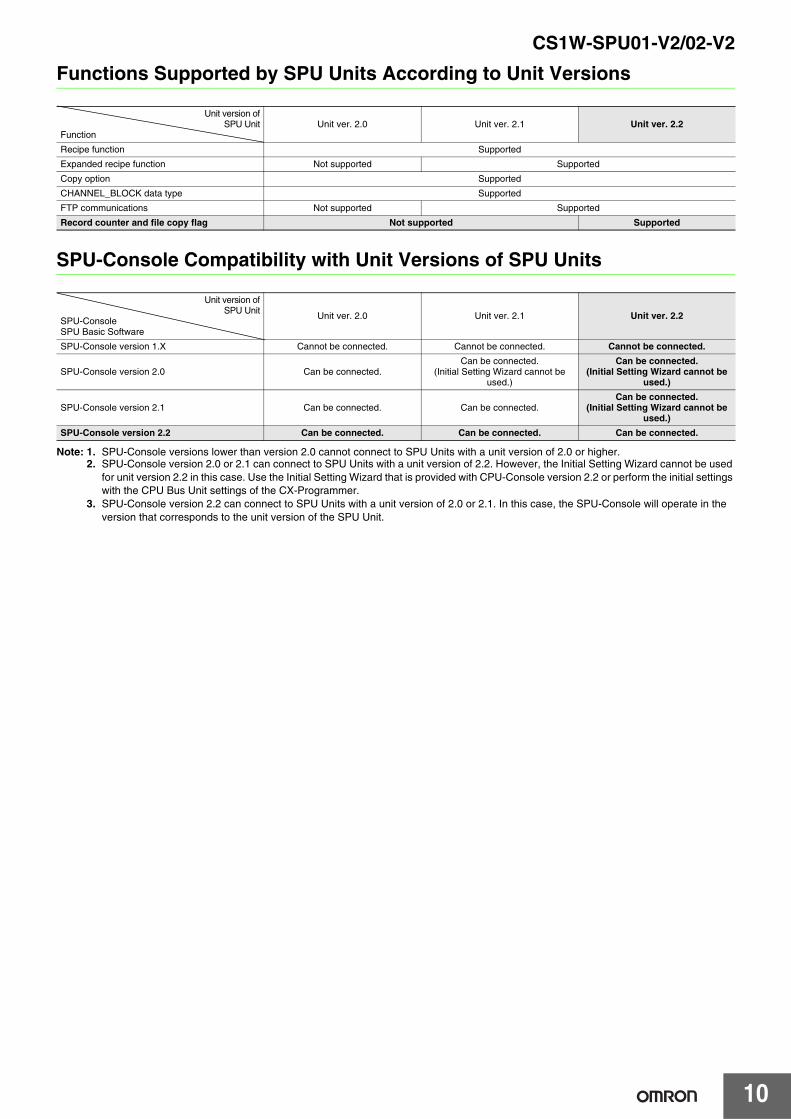
Functions Supported by SPU Units According to Unit Versions
SPU-Console Compatibility with Unit Versions of SPU Units
Note: 1. SPU-Console versions lower than version 2.0 cannot connect to SPU Units with a unit version of 2.0 or higher.2. SPU-Console version 2.0 or 2.1 can connect to SPU Units with a unit version of 2.2. However, the Initial Setting Wizard cannot be used
for unit version 2.2 in this case. Use the Initial Setting Wizard that is provided with CPU-Console version 2.2 or perform the initial settings with the CPU Bus Unit settings of the CX-Programmer.
3. SPU-Console version 2.2 can connect to SPU Units with a unit version of 2.0 or 2.1. In this case, the SPU-Console will operate in the version that corresponds to the unit version of the SPU Unit.
Unit version ofSPU Unit
FunctionUnit ver. 2.0 Unit ver. 2.1 Unit ver. 2.2
Recipe function Supported
Expanded recipe function Not supported Supported
Copy option Supported
CHANNEL_BLOCK data type Supported
FTP communications Not supported Supported
Record counter and file copy flag Not supported Supported
Unit version ofSPU Unit
SPU-ConsoleSPU Basic Software
Unit ver. 2.0 Unit ver. 2.1 Unit ver. 2.2
SPU-Console version 1.X Cannot be connected. Cannot be connected. Cannot be connected.
SPU-Console version 2.0 Can be connected.Can be connected.
(Initial Setting Wizard cannot be used.)
Can be connected.(Initial Setting Wizard cannot be
used.)
SPU-Console version 2.1 Can be connected. Can be connected.Can be connected.
(Initial Setting Wizard cannot be used.)
SPU-Console version 2.2 Can be connected. Can be connected. Can be connected.

CS1W-SPU01-V2/02-V2
11
External InterfaceCS1W-SPU01/SPU02-V2Here, the CS1W-SPU02-V2, which has two LAN ports, is taken as an example. The CS1W-SPU01-V2 has only one LAN port.
Name Function
Unit number switch (UNIT NO.) Sets the unit number of the SPU Unit as a one-digit hexadecimal value. Do not set the same unit number for more than one CPU Bus Unit under the same CPU Unit.
DIP switch (DIP SW) Used for system settings.
Card button (CARD SW) Press this button to allow the Memory Card inserted in the PC card slot to be removed.
Card eject button Press to remove the PC card.
Card holder Holds the PC card.
Select switch Sets the command to be executed. The command number will be displayed on the seven-segment display.
Enter button Executes the command set using the select switch.
Indicators The following indicators show the operating status of the Unit: RUN, ERC, ERH, and COMM.
Seven-segment displayDisplays error information and the operating status of the SPU Unit. Displays the command number when the select switch is operated.Displays the IP address and other results of command execution.
LAN indicator Indicates the operating status of the LAN port.
Card indicator Indicates the operating status of the PC card.
PF-IN indicator Lights when the power failure input is received from a UPS or other device.
PC card slot A slot used to insert a card conforming to PC Card Type II.
Communications ports LAN1/LAN2 LAN communications ports. Connect to 10Base-T/100Base-TX cables.
COMM port For future expansion.
PF-IN terminals Connected to the power failure input from a UPS or other device.
Recognition retry switch Refer to the SPU Units Operation Manual (Cat. No. 236), Starting CPU Unit Operation Immediately upon Power Application.
SPU02
LAN1
LAN2
LAN1
LAN2
CARD
UNIT NO.
CARD SW
COMM
PF-IN
DIPSW
SELECT
ENTER
CSCSRUNRUNERCERCERHERHCOMMCOMM
0Unit numberswitch
Enter button
Select switch
DIP switch
7-segment display
Card eject button
LAN ports(CS1W-SPU01-V2: One port,CS1W-SPU02-V2: Two ports)
PF-IN terminals
COMM port
Indicators
Card button
Card indicator
PC card slot
LAN indicator
Card holder
PF-IN indicatorRecognition retry switch

CS1W-SPU01-V2/02-V2
12
Connecting the Power Failure Signal
CS1W-SPU01/SPU02-V2Connect the power failure signal output line from a UPS or other device to the power failure input terminals on the SPU Unit.
Note:Tighten the cable screws to a torque of 0.3 N·m.
Signal Input Specifications
Uninterruptive Power Supply for Checking Operation• BU70XS (OMRON) operating temperature range: 0 to 40°C• BU606F (OMRON) operating temperature range: 0 to 55°C
Item Specification
Rated input voltage 24 VDC (+10% / -15%)
Input impedance 2 kΩ
Input current 10 mA (typical)
ON voltage 17.4 V min.
OFF voltage 5 V max.
Signals
IN
COM
MC1.5/2-STF-3.81
(Phoenix Contact)
Inte
rnal
circ
uits
2 KΩ
510 Ω
IN
COM
24 VDC
Input indicator

CS1W-SPU01-V2/02-V2
13
Dimensions (Unit: mm)
CS1W-SPU01-V2 / CS1W-SPU02-V2
Note: The appearance varies with the model.
Related Manuals
Name Cat. No. Contents
CS1W-SPU01-V2/SPU02-V2CJ1W-SPU01-V2SYSMAC SPU Units Operation Manual
V236 Describes the installation and operation of the SPU Units.
WS02-SPTC1-V2SPU-Console Ver. 2.1 Operation Manual V237 Describes the installation and operation of the SPU-Console Ver. 2.1.
WS02-EDMC1-V2SYSMAC SPU Data Management Middleware User’s Manual V232 Describes the installation and operation of the SPU Data Management
Middleware (EDMS).
10135
130
20

Terms and Conditions Agreement Read and understand this catalog. Please read and understand this catalog before purchasing the products. Please consult your OMRON representative if you have any questions or comments. Warranties. (a) Exclusive Warranty. Omron’s exclusive warranty is that the Products will be free from defects in materials and workmanship for a period of twelve months from the date of sale by Omron (or such other period expressed in writing by Omron). Omron disclaims all other warranties, express or implied. (b) Limitations. OMRON MAKES NO WARRANTY OR REPRESENTATION, EXPRESS OR IMPLIED, ABOUT NON-INFRINGEMENT, MERCHANTABILITY OR FITNESS FOR A PARTICULAR PURPOSE OF THE PRODUCTS. BUYER ACKNOWLEDGES THAT IT ALONE HAS DETERMINED THAT THE PRODUCTS WILL SUITABLY MEET THE REQUIREMENTS OF THEIR INTENDED USE. Omron further disclaims all warranties and responsibility of any type for claims or expenses based on infringement by the Products or otherwise of any intellectual property right. (c) Buyer Remedy. Omron’s sole obligation hereunder shall be, at Omron’s election, to (i) replace (in the form originally shipped with Buyer responsible for labor charges for removal or replacement thereof) the non-complying Product, (ii) repair the non-complying Product, or (iii) repay or credit Buyer an amount equal to the purchase price of the non-complying Product; provided that in no event shall Omron be responsible for warranty, repair, indemnity or any other claims or expenses regarding the Products unless Omron’s analysis confirms that the Products were properly handled, stored, installed and maintained and not subject to contamination, abuse, misuse or inappropriate modification. Return of any Products by Buyer must be approved in writing by Omron before shipment. Omron Companies shall not be liable for the suitability or unsuitability or the results from the use of Products in combination with any electrical or electronic components, circuits, system assemblies or any other materials or substances or environments. Any advice, recommendations or information given orally or in writing, are not to be construed as an amendment or addition to the above warranty. See http://www.omron.com/global/ or contact your Omron representative for published information. Limitation on Liability; Etc. OMRON COMPANIES SHALL NOT BE LIABLE FOR SPECIAL, INDIRECT, INCIDENTAL, OR CONSEQUENTIAL DAMAGES, LOSS OF PROFITS OR PRODUCTION OR COMMERCIAL LOSS IN ANY WAY CONNECTED WITH THE PRODUCTS, WHETHER SUCH CLAIM IS BASED IN CONTRACT, WARRANTY, NEGLIGENCE OR STRICT LIABILITY. Further, in no event shall liability of Omron Companies exceed the individual price of the Product on which liability is asserted. Suitability of Use. Omron Companies shall not be responsible for conformity with any standards, codes or regulations which apply to the combination of the Product in the Buyer’s application or use of the Product. At Buyer’s request, Omron will provide applicable third party certification documents identifying ratings and limitations of use which apply to the Product. This information by itself is not sufficient for a complete determination of the suitability of the Product in combination with the end product, machine, system, or other application or use. Buyer shall be solely responsible for determining appropriateness of the particular Product with respect to Buyer’s application, product or system. Buyer shall take application responsibility in all cases. NEVER USE THE PRODUCT FOR AN APPLICATION INVOLVING SERIOUS RISK TO LIFE OR PROPERTY OR IN LARGE QUANTITIES WITHOUT ENSURING THAT THE SYSTEM AS A WHOLE HAS BEEN DESIGNED TO ADDRESS THE RISKS, AND THAT THE OMRON PRODUCT(S) IS PROPERLY RATED AND INSTALLED FOR THE INTENDED USE WITHIN THE OVERALL EQUIPMENT OR SYSTEM. Programmable Products. Omron Companies shall not be responsible for the user’s programming of a programmable Product, or any consequence thereof. Performance Data. Data presented in Omron Company websites, catalogs and other materials is provided as a guide for the user in determining suitability and does not constitute a warranty. It may represent the result of Omron’s test conditions, and the user must correlate it to actual application requirements. Actual performance is subject to the Omron’s Warranty and Limitations of Liability. Change in Specifications. Product specifications and accessories may be changed at any time based on improvements and other reasons. It is our practice to change part numbers when published ratings or features are changed, or when significant construction changes are made. However, some specifications of the Product may be changed without any notice. When in doubt, special part numbers may be assigned to fix or establish key specifications for your application. Please consult with your Omron’s representative at any time to confirm actual specifications of purchased Product. Errors and Omissions. Information presented by Omron Companies has been checked and is believed to be accurate; however, no responsibility is assumed for clerical, typographical or proofreading errors or omissions.
2014.1
In the interest of product improvement, specifications are subject to change without notice.
OMRON Corporation Industrial Automation Company http://www.ia.omron.com/
(c)Copyright OMRON Corporation 2014 All Right Reserved.

Mouser Electronics
Authorized Distributor
Click to View Pricing, Inventory, Delivery & Lifecycle Information: Omron:
CS1W-SPU02-V2 CS1W-SPU01-V2