crystal plasticity simulation considering oxidation along
TRANSCRIPT

Crystal Plasticity Simulation Considering Oxidation along Grain Boundaryand Effect of Grain Size on Stress Corrosion Cracking
Yoshiteru Aoyagi+ and Yoshiyuki Kaji
Nuclear Science and Engineering Directorate, Japan Atomic Energy Agency, Naka-gun, Ibaraki 319-1195, Japan
Stress corrosion cracking is a critical concern for light water reactors because it can degrade structural components over a long period. Ittakes the form of intergranular stress corrosion cracking (IGSCC). Many studies on IGSCC have been conducted over several decades in thepast. However, the mechanism of IGSCC initiation and propagation is still not fully understood. In this study, a crystal plasticity modelexpressing IGSCC is proposed by considering information about the oxidation along the grain boundaries and the failure of an oxide film causedby the localization of a deformation. From a crystal plasticity finite element analysis and an oxygen reaction-diffusion finite difference analysisbased on the presented model, the IGSCC is numerically reproduced, and we discuss the effect of grain size on the crack propagation behavior.[doi:10.2320/matertrans.MD201126]
(Received August 1, 2011; Accepted October 28, 2011; Published December 7, 2011)
Keywords: intergranular stress corrosion cracking, crystal plasticity, grain boundary, oxygen reaction-diffusion equation, crack propagation,grain size
1. Introduction
Stress corrosion cracking (SCC) in light water reactors(LWRs) has been the cause of significant economic lossesas a result of disruptions in power plant availability andthe costs associated with SCC mitigation and remediation.Recently, SCC has been found in boiling water reactor(BWR) components, such as core shrouds and primary looprecirculation piping fabricated with low-carbon stainlesssteels,1,2) as well as in pressurized water reactor (PWR)components, such as the vessel head penetrations, bottommounted instrument nozzles, and primary water inlet nozzlesof steam generators fabricated with Alloy 600 and its weldmetals.35) Consequently, there is incentive for developingquantitative methods for evaluating the reliability and theremaining SCC lifetimes of structural materials in LWRs.Ford and Andresen proposed a crack growth rate predictionmodel based on the slip dissolution/oxidation mechanismfor SCC.6,7) Shoji et al. proposed a theoretical crack growthrate equation based on a theoretical crack tip strain rateformulation and the asymptotic field by considering thesolid state oxidation mechanism.811) Bruemmer et al.analyzed a crack tip oxide film using an analyticaltransmission electron microscope (ATEM) and reported thatthe mass transport process in a solid state oxide film couldbe the key element process for crack growth.12) Staehle alsodiscussed the visibility of a film rupture event in a tightcrack tip.13) In addition, Fukuya et al.14) performed detailedobservations of the crack tip of an active stress corrosioncrack in the highly irradiated Type 316 stainless steel of apressurized water reactor (PWR), which was initiated in theprimary system simulated water. They showed that anoxygen atom could be observed up to a distance of around10 nm from the crack tip. Yamaguchi15) showed that the grainboundary cohesion strength decreased at the 3 grainboundary of an iron-based coincidence site lattice by thesegregation of oxygen atoms. Therefore, a solid state
oxidation mechanism might be the critical element processin SCC. Recently, multi-scale modeling has also beenperformed for the structural materials of a reactor core andthe primary coolant components to ensure their safe andreliable operation. In particular, some computational ap-proaches have been proposed for the simulation ofintergranular cracks in a polycrystalline aggregate.1618) Thesurface of the core shroud of a nuclear reactor is ground toincrease the out-of-roundness. Therefore, the surface of theshroud has a severe deformation condition, and the grainsize decreases to several microns or less. In the case of theshroud of a nuclear reactor, a crack is generated at the surfaceof the shroud. SCC in a shroud can be said to start atpolycrystalline metals with a grain size smaller than 1 µm,namely, “bulk nanostructured metals”. It is important toevaluate the crack behavior on these bulk nanostructuredmetals to investigate the SCC of a shroud.
In this work, in order to predict IGSCC numerically,we introduce information about the oxidation along thegrain boundaries and the failure of an oxide film causedby deformation localization in a crystal plasticity model.Based on the results obtained from a crystal plasticity finiteelement (FE) analysis and oxygen reaction-diffusion finitedifference (FD) analysis using the presented model, wediscuss the effect of the grain size on the crack propagationbehavior.
2. Models of SCC
2.1 Oxygen reaction-diffusion equationIn this study, we assume that oxygen atoms diffuse only
along grain boundaries, because the value of the diffusioncoefficient of oxygen atoms along the grain boundary islarger than that inside the grain. Considering that themovement of oxygen atoms is caused by a potentialoriginating in a stress that is normal to the plane of the grainboundary and that metals are oxidized by the diffusion ofoxygen atoms, a reaction-diffusion equation for the oxygenalong the grain boundaries can be written as follows+Corresponding author, E-mail: [email protected]
Materials Transactions, Vol. 53, No. 1 (2012) pp. 161 to 166Special Issue on Advanced Materials Science in Bulk Nanostructured Metals©2011 The Japan Institute of Metals

_C ¼ Dr2C�D�
kTr � ðCr·Þ �KC2; ð1Þ
where D is the diffusion coefficient of oxygen atoms, C is theconcentration of oxygen atoms, + is the volume per atom, kis the Boltzmann constant, and T is the absolute temperature.Moreover, · is the normal stress component that applies to agrain boundary, which is expressed by
· ¼ T:ðn� nÞ; ð2Þwhere T denotes the Cauchy stress tensor and n is the unitvector normal to a grain boundary. In eq. (1), the first andsecond terms express the phenomena of the diffusion ofoxygen atoms and the movement of oxygen atoms causedby the gradient of stress. The third term on the right siderepresents an oxidation reaction, where K represents thereaction rate coefficient for the oxidation reaction. Theoccurrence of a second-order oxidation reaction is assumed inthis study. Then, the concentration rate of the metal in thegrain boundaries is given by
_M ¼ �KC2; ð3ÞwhereM is the concentration of metal. Equation (3) expressesthe decrease in M originating in the oxidation reaction.
2.2 Local criterion of crack progressWhen a crack is generated, elastic strain energy is
translated into surface energy. In other words, when thedensity of local elastic strain energy Ee (the elastic strainenergy per unit volume) exceeds the density of surfaceenergy EC (the surface energy per unit volume), a crackpropagates. The density of elastic strain energy Ee is given by
Ee ¼Z
T � Dedt; ð4Þ
where De is the elastic deformation rate tensor. Whenconsidering the decrease in metal atoms caused by theoxidation reaction, we model EC such as
EC ¼ 2e�A 1� eM0 �M
M0
� �; ð5Þ
where e! is the density of the surface energy per unit area, Ais the area of the generated crack, e is a numerical parameterexpressing the effect of oxidation on cracking, and M0 is theinitial concentration of the metal. Equation (5) indicates thata crack always propagates when an amount of 1/e of themetal is oxidized. When e > 1, EC becomes negative with theprogress of the oxidation. However, in a situation where acrack is not generated, EC > 0 is derived from EC > Ee andEe > 0.
2.3 Model for failure of oxide filmThe oxidation films generated on metal surfaces are
damaged by the slip deformation of the metal. In orderto represent the process where oxygen atoms enter grainboundaries through such damaged oxide films, we proposethe following model for the failure of an oxide film.
CS ¼X¡
£ ð¡Þsð¡Þ � nCe; ð6Þ
where CS denotes the concentration of oxygen on a metalsurface, £ (¡) is the slip rate of slip system ¡, s(¡) is the slipdirection vector, and Ce is the concentration of oxygen in theenvironment. When eq. (6) is used as the boundary conditionof eq. (1), the result indicates that oxygen atoms are allowedto enter grain boundaries from new surfaces generated by slipdeformation.
3. Crystal Plasticity Model
Information about the stress field can be obtained using thecrystal plasticity model proposed by Peirce et al.19) Thecrystal plasticity-type elasto-viscoplastic constitutive equa-tion is written in the form
Tr¼ Ce : D� Ce :
Xa
Pð¡ÞS _£ ð¡Þ; ð7Þ
where Tris the Mandel-Kratochvil rate of the Cauchy stress
tensor, Ce is the anisotropic elastic moduli, D is thedeformation rate tensor, Pð¡Þ
S is the Schmid tensor on slipsystem ¡, and _£ ð¡Þ is the slip rate. This slip rate, _£ ð¡Þ, is givenby the rate dependent hardening law of Pan-Rice, as follows:
_£ ð¡Þ ¼ _£ ð¡Þ0 sgnð¸ð¡ÞÞ ¸
ð¡Þ
gð¡Þ
��������1=m
; ð8Þ
where _£ ð¡Þ0 denotes the referential slip rate, ¸ (¡) is the resolved
shear stress, g(¡) is the flow stress, and m is the strain ratesensitivity. The evolution equation of flow stress isrepresented by
_gð¡Þ ¼X¢
hð¡¢Þj _£ ð¢Þj; ð9Þ
where h(¡¢) is the hardening modulus. Various models forh(¡¢) have been proposed by many researchers, e.g., a modelbased on the geometrically necessary dislocation density.20)
In this study, to simplify the calculation, we apply thefollowing function of the total slip, £, to the hardeningmodulus, h(¡¢):
hð¡¢Þ ¼ h0 sech2 h0
¸s � ¸0£
� �; ð10Þ
where h0 is the initial hardening ratio, ¸s is the saturated valueof the resolved shear stress, and ¸0 is the initial flow stress.
4. Results and Discussions
4.1 Computational modelIn a crystal plasticity FE simulation, a polycrystal of
stainless steel under a plane strain condition is assumed andthe number of grains is (a) 225 for a fine grain model or (b)900 for a coarse grain model [see Fig. 1]. The initial widthand height of the specimen are 120 and 30 µm, respectively.Delaunay triangulation is adopted for the meshing of theFEM to express inhomogeneity in the shape of the grains.The number of elements used for the FEM is (a) 397972 or(b) 395621. The initial crack depicted by the bold line inFig. 1 occurs along the initial grain boundary. The lengthof this initial crack in the horizontal direction is 6 µm.Two types of hardening parameters are used here, i.e.,(a) ¸0 = 150MPa, ¸s = 240MPa, and h0 = 500MPa, for a
Y. Aoyagi and Y. Kaji162

soft material and (b) ¸0 = 200MPa, ¸s = 260MPa, andh0 = 180MPa, for a hard material. The nominal stressnominal strain curves obtained using calculations without theinitial crack are shown in Fig. 2. In these calculations, thecoarse grain and fine grain models shown in Fig. 1 areapplied to the soft and hard materials, respectively. In thissimulation, we establish these parameters so that the yieldstress and hardening ratio of the coarse grain model becomehigher and lower than those of the fine grain model,respectively. In order to investigate the effects of the grainsize and mechanical property of the material on cracking,we conduct crystal plasticity calculations using the threedifferent conditions given in Table 1. Note that the actualmaterials correspond to model A and model C, i.e., model Bis a virtual material, used for investigating the effects of thegrain size and material property. The other material constantsand numerical parameters are given by
D ¼ 0:017 �m2=s; K ¼ 1000m3=ðmol�sÞ;D
�
kT¼ 11:1 nm2=ðs�MPaÞ; 2e�A ¼ 8MPa;
M0 ¼ 140:6 kmol=m3; e ¼ 140600;
_£ ð¡Þ0 ¼ 0:001 s�1; m ¼ 0:005
9>>>>>=>>>>>;ð11Þ
Note that we assume that the area of the generated crack isconstant because the sizes of the elements for the FEM arealmost uniform to simplify the calculation. To maintain anelastic condition macroscopically, a constant load of 200MPais applied at the upper end of the specimen. We conduct a
pseudo-three-dimensional computation,21) which assumes aplane strain condition only in the FE simulation by restrictingthe three-dimensional deformation caused by the activationof twelve slip systems of the FCC crystal to two-dimensionalcomponents on an observation plane. The initial crystalorientation of each grain is decided randomly, while weassume that the diffusion and reaction of oxygen occur onlyalong the initial grain boundaries. Therefore, eq. (1) isdiscretized using finite difference method (FDM) by adoptingline elements along the initial grain boundaries. Only theright side of the specimen is exposed to the environment, andthe initial oxygen concentrations in the environment andmaterial are 0.001mol/m3 (about 30 ppm) and 0mol/m3,respectively. The oxygen concentration at the surface of thespecimen is calculated using eq. (6), and this value is used asa boundary condition for the reaction-diffusion eq. (1). As aresult of the generation of a crack, the connection betweenthe FEM nodes along the grain boundaries is cut, and in thiscase, the density of the elastic strain energy expressed byeq. (4) exceeds the density of the surface energy representedby eq. (5). Both the energy densities are calculated at eachnode of the FEM. The average value of all the elementscontacting a node is used as the density of the elastic strainenergy at the node. On the other hand, the density of thesurface energy is obtained at lattice points of the FDM, whichcoincide with the FEM nodes.
4.2 DiscussionFigure 3 shows the distributions of the equivalent stress
and equivalent plastic strain of model A when the cracklength in the horizontal direction reaches 54 µm. In thedistributions shown, the bold black lines represent generated
120 µm
30 µ
m
120 µm
30 µ
m
(b)
(a)
Fig. 1 Computational models of polycrystals with (a) 225 and (b) 900grains.
Nominal strain [%]
Nom
inal
str
ess
[MPa
]
500
400
300
200
100
00 4 8
Hard steel
Constant loadSoft steel
600
Fig. 2 Nominal stress versus nominal strain curves.
Table 1 Models of materials used in present simulation.
Number of grains Hardening parameters
Model A 225 ¸0 = 150MPa, ¸s = 240MPa, h0 = 500MPa
Model B 900 ¸0 = 150MPa, ¸s = 240MPa, h0 = 500MPa
Model C 900 ¸0 = 200MPa, ¸s = 260MPa, h0 = 180MPa
(a)
600 MPa0 MPa
(b)
0.0050.000
Fig. 3 Distribution of (a) equivalent stress and (b) equivalent plastic strainof model A (t = 49.84Ms).
Crystal Plasticity Simulation Considering Oxidation along Grain Boundary and Effect of Grain Size 163
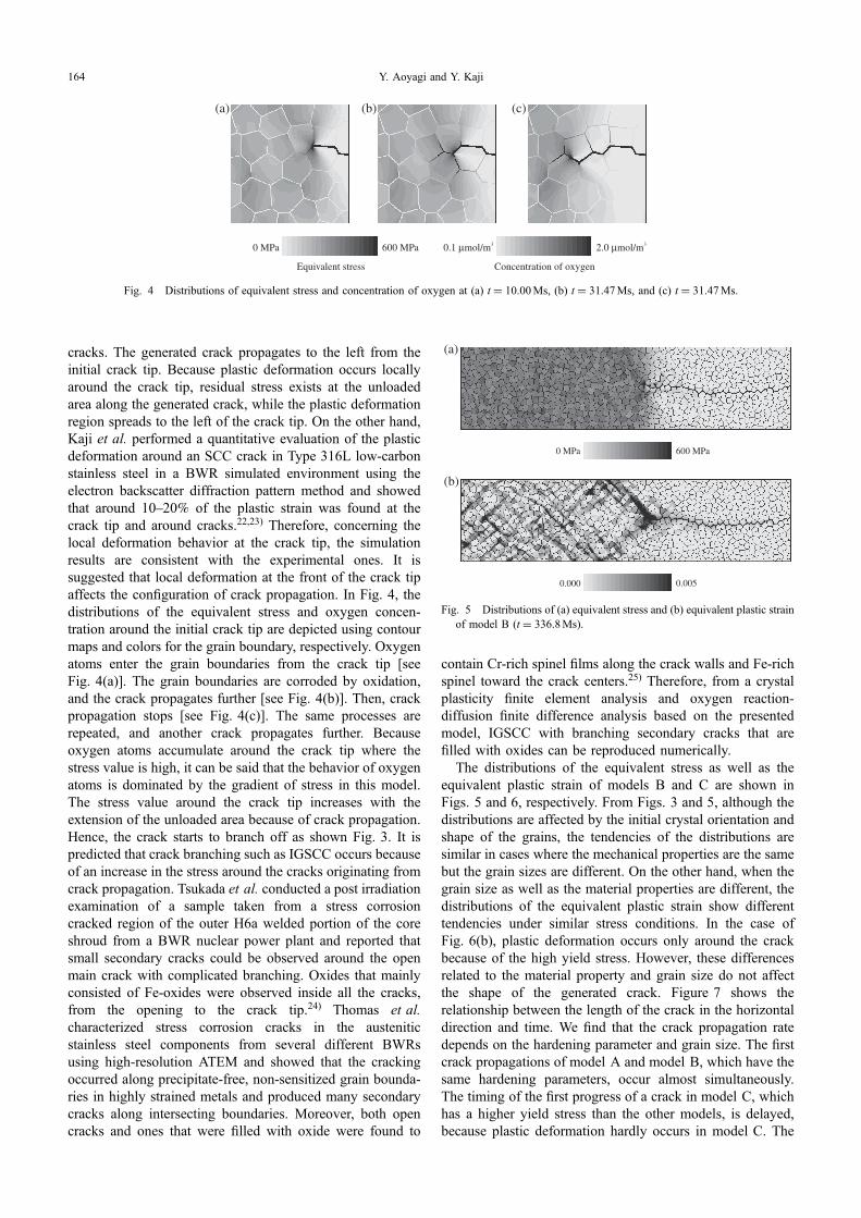
cracks. The generated crack propagates to the left from theinitial crack tip. Because plastic deformation occurs locallyaround the crack tip, residual stress exists at the unloadedarea along the generated crack, while the plastic deformationregion spreads to the left of the crack tip. On the other hand,Kaji et al. performed a quantitative evaluation of the plasticdeformation around an SCC crack in Type 316L low-carbonstainless steel in a BWR simulated environment using theelectron backscatter diffraction pattern method and showedthat around 1020% of the plastic strain was found at thecrack tip and around cracks.22,23) Therefore, concerning thelocal deformation behavior at the crack tip, the simulationresults are consistent with the experimental ones. It issuggested that local deformation at the front of the crack tipaffects the configuration of crack propagation. In Fig. 4, thedistributions of the equivalent stress and oxygen concen-tration around the initial crack tip are depicted using contourmaps and colors for the grain boundary, respectively. Oxygenatoms enter the grain boundaries from the crack tip [seeFig. 4(a)]. The grain boundaries are corroded by oxidation,and the crack propagates further [see Fig. 4(b)]. Then, crackpropagation stops [see Fig. 4(c)]. The same processes arerepeated, and another crack propagates further. Becauseoxygen atoms accumulate around the crack tip where thestress value is high, it can be said that the behavior of oxygenatoms is dominated by the gradient of stress in this model.The stress value around the crack tip increases with theextension of the unloaded area because of crack propagation.Hence, the crack starts to branch off as shown Fig. 3. It ispredicted that crack branching such as IGSCC occurs becauseof an increase in the stress around the cracks originating fromcrack propagation. Tsukada et al. conducted a post irradiationexamination of a sample taken from a stress corrosioncracked region of the outer H6a welded portion of the coreshroud from a BWR nuclear power plant and reported thatsmall secondary cracks could be observed around the openmain crack with complicated branching. Oxides that mainlyconsisted of Fe-oxides were observed inside all the cracks,from the opening to the crack tip.24) Thomas et al.characterized stress corrosion cracks in the austeniticstainless steel components from several different BWRsusing high-resolution ATEM and showed that the crackingoccurred along precipitate-free, non-sensitized grain bounda-ries in highly strained metals and produced many secondarycracks along intersecting boundaries. Moreover, both opencracks and ones that were filled with oxide were found to
contain Cr-rich spinel films along the crack walls and Fe-richspinel toward the crack centers.25) Therefore, from a crystalplasticity finite element analysis and oxygen reaction-diffusion finite difference analysis based on the presentedmodel, IGSCC with branching secondary cracks that arefilled with oxides can be reproduced numerically.
The distributions of the equivalent stress as well as theequivalent plastic strain of models B and C are shown inFigs. 5 and 6, respectively. From Figs. 3 and 5, although thedistributions are affected by the initial crystal orientation andshape of the grains, the tendencies of the distributions aresimilar in cases where the mechanical properties are the samebut the grain sizes are different. On the other hand, when thegrain size as well as the material properties are different, thedistributions of the equivalent plastic strain show differenttendencies under similar stress conditions. In the case ofFig. 6(b), plastic deformation occurs only around the crackbecause of the high yield stress. However, these differencesrelated to the material property and grain size do not affectthe shape of the generated crack. Figure 7 shows therelationship between the length of the crack in the horizontaldirection and time. We find that the crack propagation ratedepends on the hardening parameter and grain size. The firstcrack propagations of model A and model B, which have thesame hardening parameters, occur almost simultaneously.The timing of the first progress of a crack in model C, whichhas a higher yield stress than the other models, is delayed,because plastic deformation hardly occurs in model C. The
(a) (b) (c)
600 MPa0 MPa
Equivalent stress
2.0 µmol/m30.1 µmol/m3
Concentration of oxygen
Fig. 4 Distributions of equivalent stress and concentration of oxygen at (a) t = 10.00Ms, (b) t = 31.47Ms, and (c) t = 31.47Ms.
(a)
600 MPa0 MPa
0.0050.000
(b)
Fig. 5 Distributions of (a) equivalent stress and (b) equivalent plastic strainof model B (t = 336.8Ms).
Y. Aoyagi and Y. Kaji164

stress concentration occurs around the crack tip of model C,whose yield stress is larger than that of model B, becausemodel B can liberate the elasticity energy by plasticdeformation. Therefore, it can be said that oxygen can easilyconcentrate around the crack tip of model C. However, in thepresent simulations, considering the failure of the oxide filmbecause of slip deformation, because the oxide film ofmodel C is hardly damaged by slip deformation, the amountof oxygen entering the grain boundary is small. On the otherhand, the plastic deformation around the crack tip of model Bcauses the failure of the oxide film. As a result, the invasionof oxygen produces oxides in the grain boundary of model B.When the grain size is small, the rate of cracking is small.The propagation of the generated crack is stopped at the triplejunction of the grain boundary in this calculation. In the caseof fine grains, a crack is easy to stop with an increase in thevolume fraction of the triple junction. These results suggestthat the mechanical property of the material and the grain sizeaffect the timing of the first crack and the rate of crackpropagation, respectively. In the present calculation, weassume that the grain size is on the order of several microns.The facts that the timing of the first crack is delayed in thecase of a high strength material and that the rate of crackpropagation is lower when the grain size is small indicatesthat the IGSCC resistance of ultrafine-grained metals such asbulk nanostructured metals is high.
5. Conclusions
We proposed a crystal plasticity model that considersinformation about the oxidation along grain boundaries andthe failure of the oxide film as a result of slip deformation. Acrystal plasticity FE analysis and oxygen reaction-diffusionFD analysis based on the presented model were carried out.IGSCC was numerically reproduced and we discussed theeffect of the grain size on the propagation behavior of cracks.The conclusions obtained are summarized as follows.(1) Introducing the oxygen reaction-diffusion model, the
local criterion of crack propagation, and the oxide filmfailure model into a crystal plasticity model makes itpossible to numerically reproduce the generation andpropagation of cracks assuming the occurrence ofIGSCC.
(2) Although the crack propagation stops at one point, thecrack propagates again as a result of the oxidationcorrosion of the grain boundary.
(3) The mechanical property of the material and the grainsize affect the timing of the first crack and the crackpropagation rate, respectively.
Acknowledgments
This study was financially supported by Grants-in-Aidfor Scientific Research on an Innovative Area of “BulkNanostructured Metals”, from MEXT, Japan (contactNo. 22102007), and the authors deeply appreciate thesupport received.
REFERENCES
1) T. Shoji: Proc. 11th Int. Symp. Environ. Degradation of Materials inNuclear Power Systems®Water reactors, (ANS, 2003) pp. 588598.
2) S. Suzuki, K. Kumagai, C. Shitara, J. Mizutani, A. Sakashita, H.Tohkuma and H. Yamashita: Maintenology 3 (2004) 6570.
3) P. M. Scott and C. Benhamou: Proc. 10th Int. Symp. Environ.Degradation of Materials in Nuclear Power Systems®Water reactors,(NACE, 2001) CD-ROM.
4) P. M. Scott and P. Combrade: Proc. 11th Int. Symp. Environ.Degradation of Materials in Nuclear Power Systems®Water reactors,(ANS, 2003) CD-ROM.
5) Nuclear and Industrial Safety Agency (NISA), Feb. 05, (2008).6) P. L. Andresen and F. P. Ford: Mater. Sci. Eng. A 103 (1988) 167
184.7) F. P. Ford: Corrosion 52 (1996) 375395.8) T. Shoji, Z. P. Lu and Y. Takeda: ASME Pressure Vessels and Piping
Division Conference (ASME PVP 2007/Creep8), (ASME, 2007).9) T. Shoji, X. P. Lu, Y. Takeda, H. Murakami and C. Y. Fu: ASME
Pressure Vessels and Piping Division Conference (ASME PVP 2008),(ASME, 2008).
10) T. Shoji, Z. P. Lu, N. K. Das, H. Murakami, Y. Takeda and T. Ismail:ASME Pressure Vessels and Piping Division Conference (ASME PVP2009), (ASME, 2009).
11) T. Shoji, Z. P. Lu and H. Murakami: Corros. Sci. 52 (2010) 769779.12) S. M. Bruemmer and L. E. Thomas: Surf. Interface Anal. 31 (2001)
571581.13) R. W. Staehle: Proc. 13th Int. Symp. Environ. Degradation of Materials
in Nuclear Power Systems®Water reactors, (CNS, 2007) CD-ROM.14) K. Fukuya, H. Nishioka, K. Fujii and H. Kitsunai: INSS Journal 15
(2008) 152161 (in Japanese).15) M. Yamaguchi: J. Japan Inst. Metals 72 (2008) 657666 (in Japanese).16) M. Kamaya and M. Itakura: Eng. Fract. Mech. 76 (2009) 386401.17) T. J. Marrow, L. Babout, A. P. Jivkov, P. Wood, D. Engelberg, N.
(a)
600 MPa0 MPa
(b)
0.0050.000
Fig. 6 Distributions of (a) equivalent stress and (b) equivalent plastic strainof model C (t = 761.2Ms).
Time [Ms]
Len
gth
of c
rack
[µm
]
60
48
36
24
12
02000 400 600 800
Model BModel A
Model C
Fig. 7 Relationship between length of crack and time.
Crystal Plasticity Simulation Considering Oxidation along Grain Boundary and Effect of Grain Size 165

Stevens, P. J. Withers and R. C. Newman: J. Nucl. Mater. 352 (2006)6274.
18) I. Simonovski and L. Cizeli: Proc. Fontevraud 7 (2007) CD-ROM.19) D. Peirce, R. J. Asaro and A. Needleman: Acta Metall. 31 (1983) 1951
1976.20) Y. Aoyagi and K. Shizawa: Int. J. Plasticity 23 (2007) 10221040.21) Y. Aoyagi, N. Horibe and K. Shizawa: Mater. Sci. Forum 584586
(2008) 10571062.22) Y. Kaji, Y. Miwa, T. Tsukada, M. Hayakawa and N. Nagashima: JAEA-
Research 2007-008 (2007) (in Japanese).
23) M. Ando, K. Nakata, M. Itow, N. Tanaka, M. Koshiishi, R. Obata, Y.Miwa, Y. Kaji and M. Hayakawa: Proc. 13th Int. Symp. Environ.Degradation of Materials in Nuclear Power Systems®Water reactors,(CNS, 2007) CD-ROM.
24) The Working Team for Examination Operation of Samples from CoreShroud at Fukushima Dai-ni Unit-3, JAERI-Tech 2004-044, (2004)(in Japanese).
25) L. Thomas, D. Edwards, K. Asano, S. Ooki and S. Bruemmer: Proc.13th Int. Symp. Environ. Degradation of Materials in Nuclear PowerSystems®Water reactors, (CNS, 2007) CD-ROM.
Y. Aoyagi and Y. Kaji166