crt video projector calibration procedure projector calibration procedure 9 step five: adjust the...
TRANSCRIPT
CRT Video ProjectorCalibration Procedure
CinemaSource Technical Bulletins. Copyright 2002 by CinemaSource, Inc.All rights reserved. Printed in the United States of America.
No part of this bulletin may be used or reproduced in any manner whatsoever without written permission,except in brief quotations embodied in critical reviews.
CinemaSource is a registered federal trademark.
For information contact: The CinemaSource Press, 18 Denbow Rd. Durham, NH 03824
CinemaSource ,18 Denbow Rd., Durham, NH 03824
cinemasource.com800-483-9778
CRT Projector Calibr ation Procedure 3
STEP ONE: VERIFY THE CORRECT SCREEN/PROJECTOR DIMENSIONS ------------------------------- 4
STEP TWO: VERIFY THE CORRECT SCANNING POLARITY -------------------------------------------------- 6
STEP THREE: CENTER THE GREEN IMAGE IN THE PICTURE TUBE -------------------------------------- 7
STEP FOUR: CENTER THE GREEN IMAGE ON THE SCREEN ------------------------------------------------ 8
STEP FIVE: ADJUST THE OPTICAL FOCUS ------------------------------------------------------------------------- 9
STEP SIX: ADJUST THE TUBE “FLAPPING” ------------------------------------------------------------------------- 10
STEP SEVEN: ADJUST THE GREEN REFERENCE IMAGE ----------------------------------------------------- 11
STEP EIGHT: ADJUST THE GREEN REFERENCE IMAGE OVERSCAN ------------------------------------- 14
STEP NINE: MATCH THE RED IMAGE TO THE GREEN REFERENCE --------------------------------------- 15
STEP TEN: MATCH THE BLUE IMAGE TO THE GREEN REFERENCE -------------------------------------- 20
STEP ELEVEN: CENTERING THE USER POSITION CONTROLS --------------------------------------------- 21
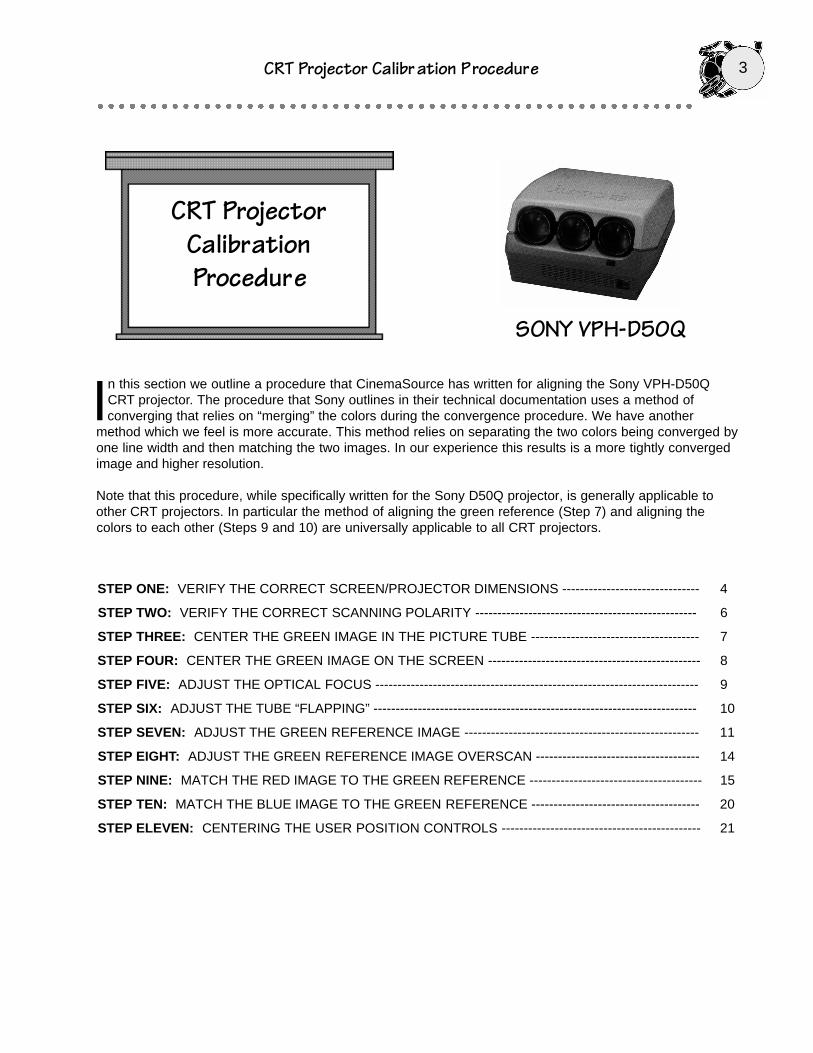
CRT ProjectorCalibrationProcedure
SONY VPH-D50Q
In this section we outline a procedure that CinemaSource has written for aligning the Sony VPH-D50QCRT projector. The procedure that Sony outlines in their technical documentation uses a method ofconverging that relies on “merging” the colors during the convergence procedure. We have another
method which we feel is more accurate. This method relies on separating the two colors being converged byone line width and then matching the two images. In our experience this results is a more tightly convergedimage and higher resolution.
Note that this procedure, while specifically written for the Sony D50Q projector, is generally applicable toother CRT projectors. In particular the method of aligning the green reference (Step 7) and aligning thecolors to each other (Steps 9 and 10) are universally applicable to all CRT projectors.
4CRT Projector Calibr ation Procedure
STEP ONE:Verify The CorrectScreen/Projector
Dimensions
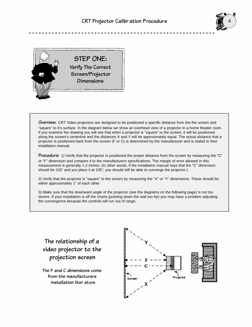
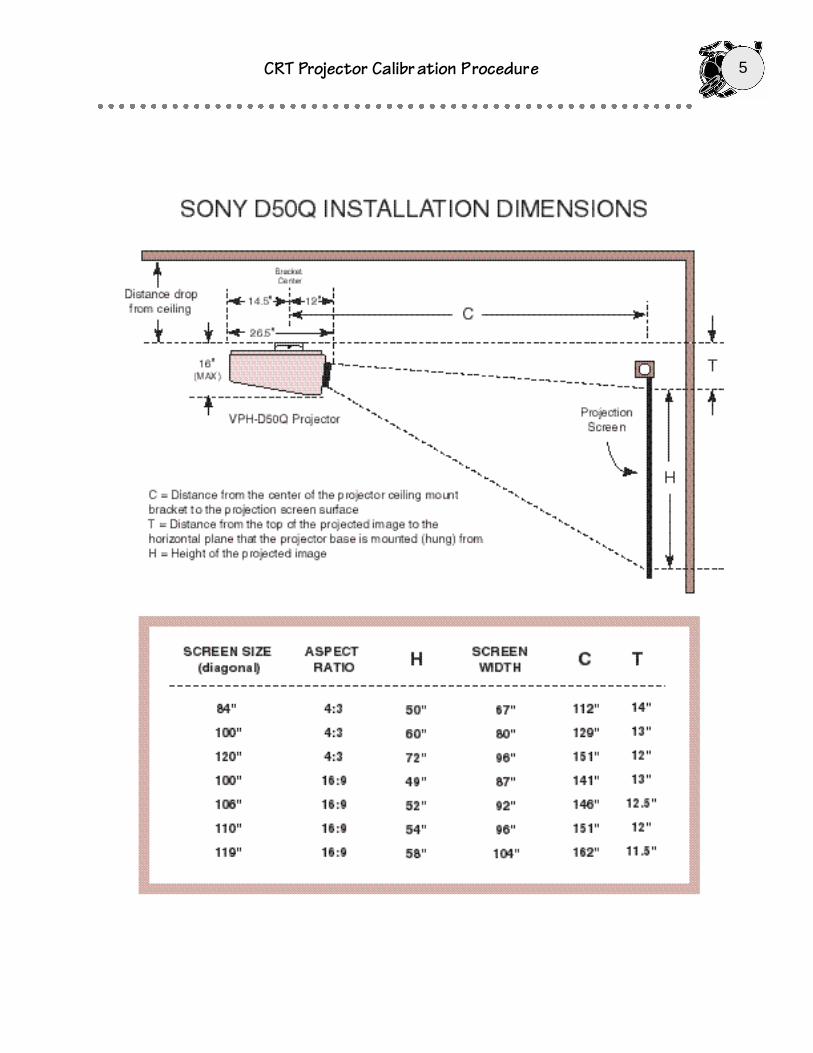
Overview: CRT Video projectors are designed to be positioned a specific distance from the the screen and“square” to it’s surface. In the diagram below we show an overhead view of a projector in a home theater room.If you examine the drawing you will see that when a projector is “square” to the screen, it will be positionedalong the screen’s centerline and the distances X and Y will be approximately equal. The actual distance that aprojector is positioned back from the screen (F or C) is determined by the manufacturer and is stated in theirinstallation manual.
Procedure: 1) Verify that the projector is positioned the proper distance from the screen by measuring the “C”or “F” dimension and compare it to the manufacturers specifications. The margin of error allowed in thismeasurement is generally 1-2 inches. (In other words, if the installation manual says that the “C” dimensionshould be 103” and you place it at 105”, you should still be able to converge the projector.)
2) Verify that the projector is “square” to the screen by measuring the “X” or “Y” dimensions. These should bewithin approximately 1” of each other.
3) Make sure that the downward angle of the projector (see the diagrams on the following page) is not toosevere. If your installation is off the charts (pointing down the wall too far) you may have a problem adjustingthe convergence because the controls will run out of range.
The relationship of a video projector to the
projection screen
The F and C dimensions comefrom the manufacturers
installation liter ature
CRT Projector Calibr ation Procedure 5

6CRT Projector Calibr ation Procedure
STEP TWOChange the projector
over to correctscanning polarity
Switching The ScanConnectors 180 Degrees
CRT Projector Calibr ation Procedure 7
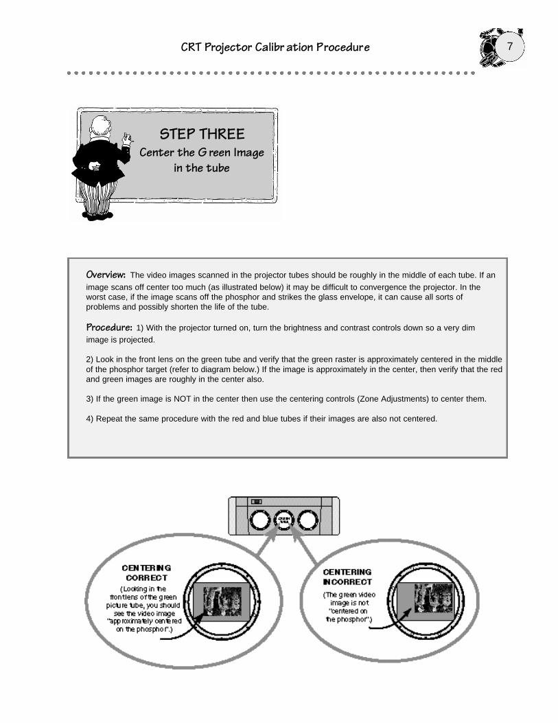
Overview: The video images scanned in the projector tubes should be roughly in the middle of each tube. If an
image scans off center too much (as illustrated below) it may be difficult to convergence the projector. In theworst case, if the image scans off the phosphor and strikes the glass envelope, it can cause all sorts ofproblems and possibly shorten the life of the tube.
Procedure: 1) With the projector turned on, turn the brightness and contrast controls down so a very dimimage is projected.
2) Look in the front lens on the green tube and verify that the green raster is approximately centered in the middleof the phosphor target (refer to diagram below.) If the image is approximately in the center, then verify that the redand green images are roughly in the center also.
3) If the green image is NOT in the center then use the centering controls (Zone Adjustments) to center them.
4) Repeat the same procedure with the red and blue tubes if their images are also not centered.
STEP THREECenter the G reen Image
in the tube
8CRT Projector Calibr ation Procedure
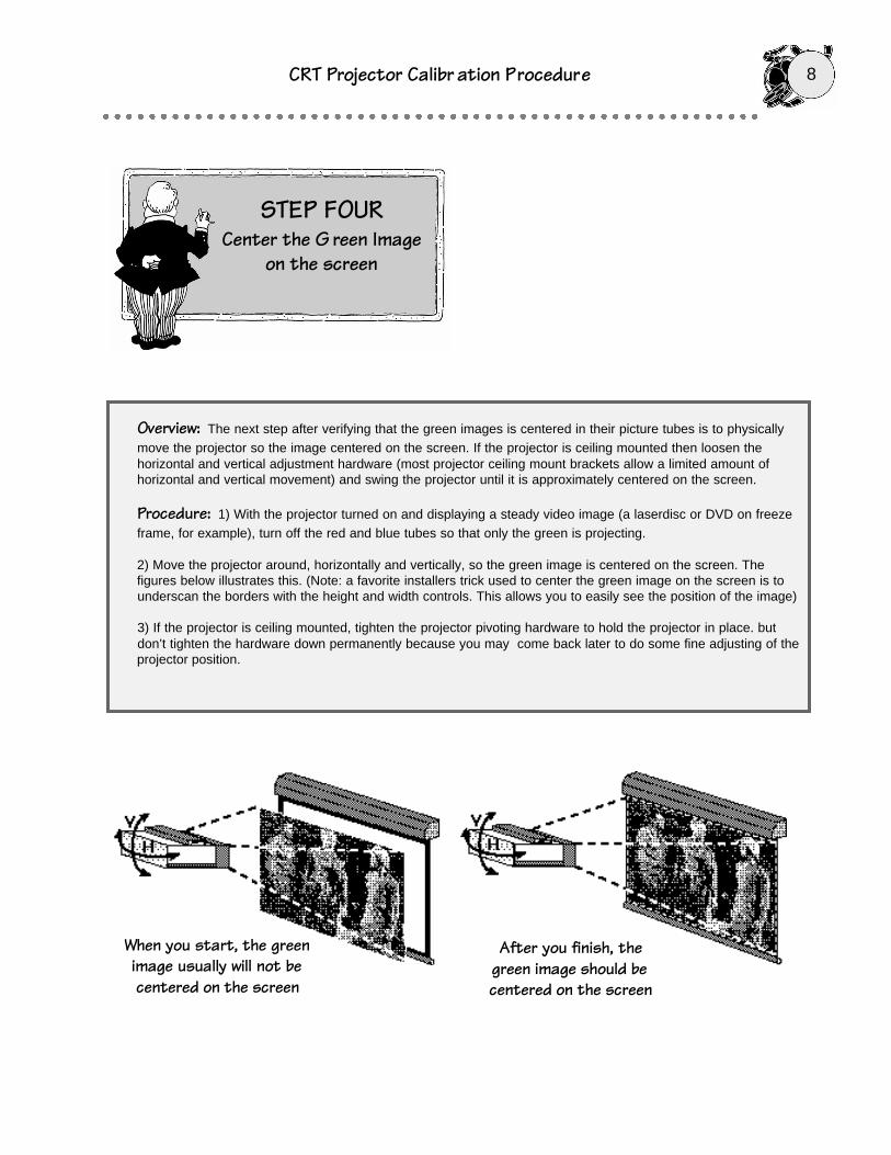
Overview: The next step after verifying that the green images is centered in their picture tubes is to physicallymove the projector so the image centered on the screen. If the projector is ceiling mounted then loosen thehorizontal and vertical adjustment hardware (most projector ceiling mount brackets allow a limited amount ofhorizontal and vertical movement) and swing the projector until it is approximately centered on the screen.
Procedure: 1) With the projector turned on and displaying a steady video image (a laserdisc or DVD on freezeframe, for example), turn off the red and blue tubes so that only the green is projecting.
2) Move the projector around, horizontally and vertically, so the green image is centered on the screen. Thefigures below illustrates this. (Note: a favorite installers trick used to center the green image on the screen is tounderscan the borders with the height and width controls. This allows you to easily see the position of the image)
3) If the projector is ceiling mounted, tighten the projector pivoting hardware to hold the projector in place. butdon’t tighten the hardware down permanently because you may come back later to do some fine adjusting of theprojector position.
When you start, the greenimage usually will not becentered on the screen
After you finish, thegreen image should becentered on the screen
STEP FOURCenter the G reen Image
on the screen
CRT Projector Calibr ation Procedure 9
STEP FIVE:Adjust The Optical
Focus
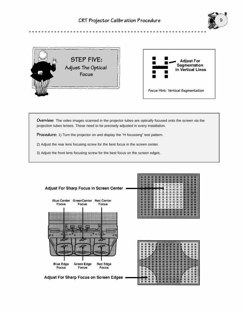
Overview: The video images scanned in the projector tubes are optically focused onto the screen via theprojection tubes lenses. These need to be precisely adjusted in every installation.
Procedure: 1) Turn the projector on and display the “H focussing” test pattern.
2) Adjust the rear lens focusing screw for the best focus in the screen center.
3) Adjust the front lens focusing screw for the best focus on the screen edges.
Focus Hint: Vertical Segmentation

10CRT Projector Calibr ation Procedure
STEP SIX:Adjust The tubes
“Flapping”
Overview: The video images scanned in the projector tubes are optically focused onto the screen via theprojection tubes lenses. After the tubes are optically focussed, the angle of the lenses needs to be adjusted forbest focus.
Procedure: 1) Turn the projector on and display the “H focussing” test pattern.
2) Adjust the green “V screw” for the best focus across all four screen edges (see diagram above). Normally youwill not have to adjust the green “H Screw”
3) Adjust the red and blue “V screw” and “H Screw” for the best focus across all four screen edges (see diagramabove).
The flapping adjustments allow you tomap the tube faceplate precisely to the
screen for best focus
Vertical Flapping
Adjustment
HorizontalFlapping
Adjustment
CRT Projector Calibr ation Procedure 11
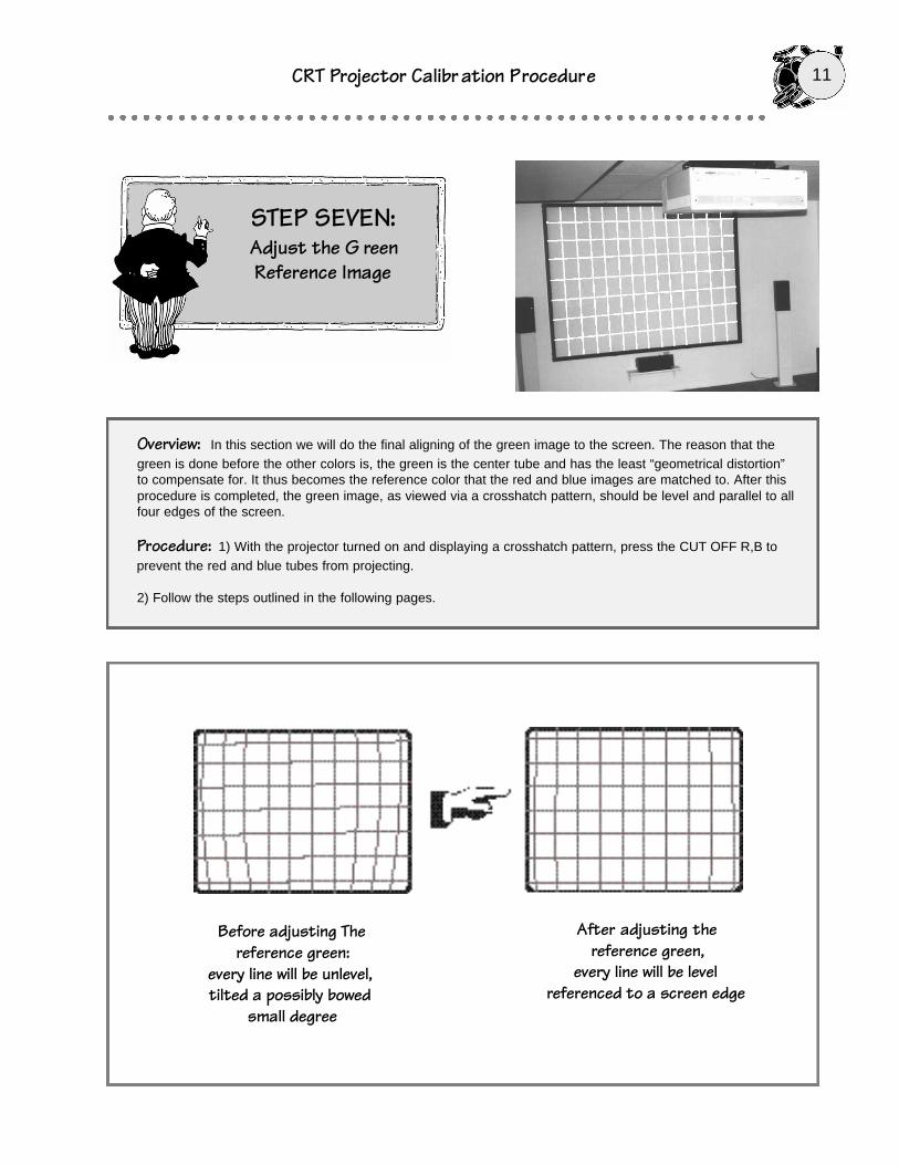
Overview: In this section we will do the final aligning of the green image to the screen. The reason that thegreen is done before the other colors is, the green is the center tube and has the least “geometrical distortion”to compensate for. It thus becomes the reference color that the red and blue images are matched to. After thisprocedure is completed, the green image, as viewed via a crosshatch pattern, should be level and parallel to allfour edges of the screen.
Procedure: 1) With the projector turned on and displaying a crosshatch pattern, press the CUT OFF R,B toprevent the red and blue tubes from projecting.
2) Follow the steps outlined in the following pages.
STEP SEVEN:Adjust the G reenReference Image
Before adjusting Thereference green:
every line will be unlevel,tilted a possibly bowed
small degree
After adjusting thereference green,
every line will be levelreferenced to a screen edge
12CRT Projector Calibr ation Procedure
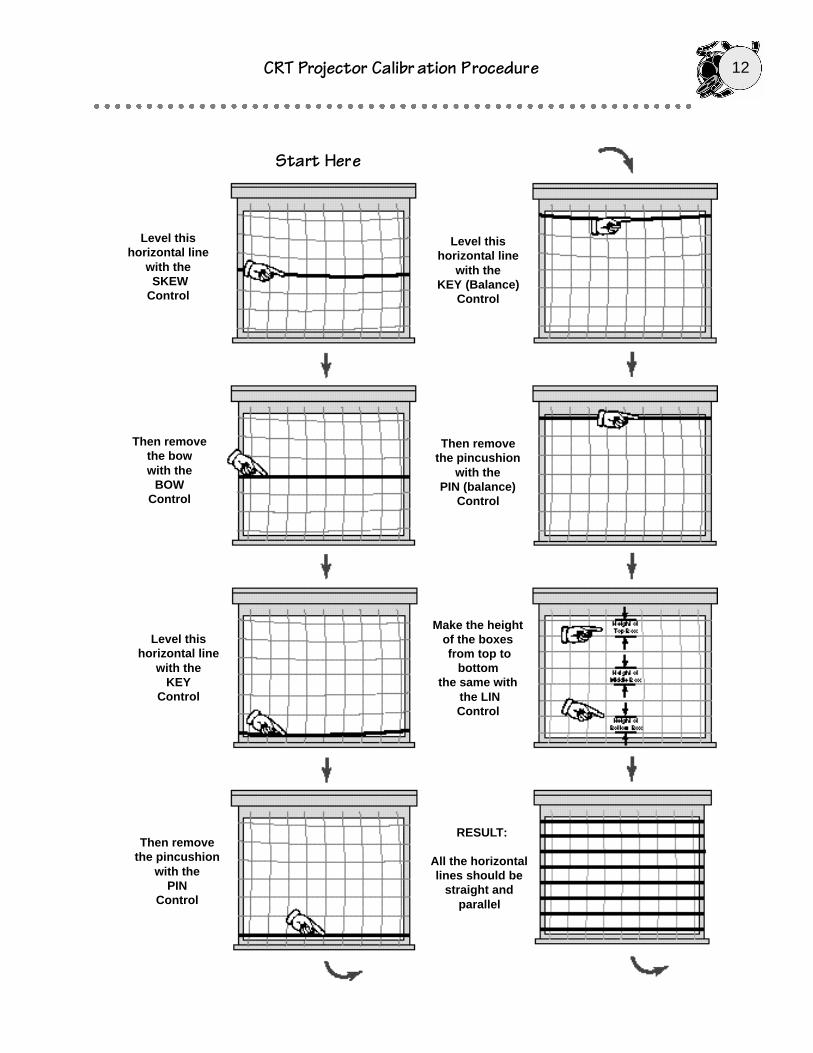
Level this horizontal line
with theSKEW
Control
Then remove the bow with the
BOW Control
Level this horizontal line
with the KEY
Control
Then remove the pincushion
with the PIN
Control
Level this horizontal line
with the KEY (Balance)
Control
Then remove the pincushion
with the PIN (balance)
Control
Make the height of the boxesfrom top to
bottom the same with
the LINControl
RESULT:
All the horizontallines should be
straight andparallel
Start Here

CRT Projector Calibr ation Procedure 13
Level this vertical line
with the KEY (balance)
Control
Then remove the bow with the
BOW Control
Level this vertical line
with the KEY
Control
Then remove the pincushion
with the PIN
Control
Level this vertical line
with the SKEWControl
Then remove the pincushion
with the PIN (balance)
Control
Make the width of the boxes
from right to leftthe same with the
LINControl
END RESULT:
All the horizontaland vertical lines
should be straight and
parallel
14CRT Projector Calibr ation Procedure
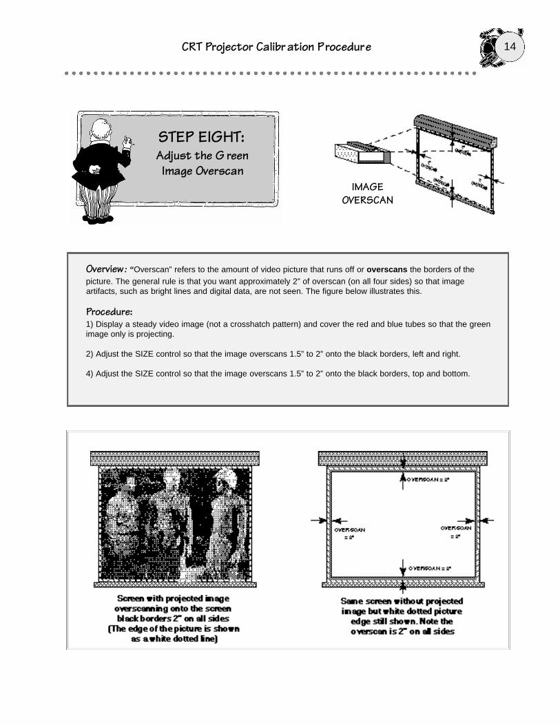
Overview : “Overscan” refers to the amount of video picture that runs off or overscans the borders of thepicture. The general rule is that you want approximately 2” of overscan (on all four sides) so that imageartifacts, such as bright lines and digital data, are not seen. The figure below illustrates this.
Procedure:1) Display a steady video image (not a crosshatch pattern) and cover the red and blue tubes so that the greenimage only is projecting.
2) Adjust the SIZE control so that the image overscans 1.5” to 2” onto the black borders, left and right.
4) Adjust the SIZE control so that the image overscans 1.5” to 2” onto the black borders, top and bottom.
STEP EIGHT:Adjust the G reenImage Overscan
IMAGEOVERSCAN

CRT Projector Calibr ation Procedure 15
Overview: In Step Seven, you adjusted the green image so that it matches the screen. The green image now
becomes your reference standard to which you match the red image to. This procedure is usually called“Dynamic Convergence, ” however, we prefer the somewhat less technical term “matching”. The procedurethat you are going to undertake here is somewhat lengthy. It will probably take you a hour or so to go throughit. We recommend that you take your time and perform this part with the room as dark as you can get it.
Procedure:
1) Turn off the blue tube so that only the green and red are projecting and put on a crosshatch pattern.
2) Closely follow the steps on the following three pages. When you have finished this red matching procedure,you should have a yellow crosshatch pattern with a minimum of color fringing in the corners.
Note: Take your time! Our experience is that few are good at converging a video projector the first time aroundbut do a lot better after a few attempts.
STEP NINE:Match the Red Image to
the Green ReferenceImage
16CRT Projector Calibr ation Procedure
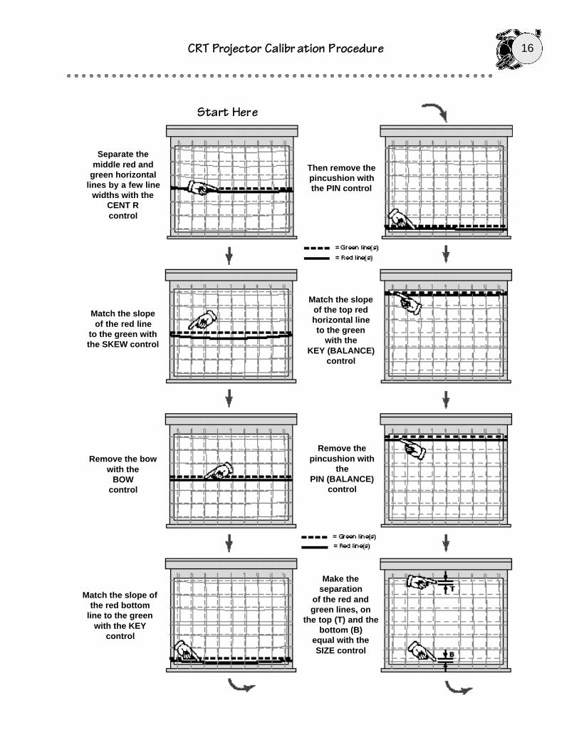
Separate themiddle red and
green horizontallines by a few line
widths with the CENT Rcontrol
Match the slopeof the red line
to the green withthe SKEW control
Remove the bowwith the
BOW control
Then remove thepincushion withthe PIN control
Match the slope ofthe red bottom
line to the greenwith the KEY
control
Match the slopeof the top redhorizontal line to the green
with the KEY (BALANCE)
control
Remove thepincushion with
the PIN (BALANCE)
control
Start Here
Make theseparation
of the red andgreen lines, on
the top (T) and thebottom (B)
equal with the SIZE control

CRT Projector Calibr ation Procedure 17
Match the tilt ofthe red line to the
green with theSKEW control
Remove the bowwith the BOW
control
RESULT:
All the red andgreen horizontal
lines lay on top ofeach other to formhorizontal yellow
lines
Make theseparation
of the red andgreen lines in themiddle (M) equalto the top(T) andbottom (B) withthe LIN control
Move the red linesdirectly over thegreen with the
R CENTcontrol
Match the tilt ofthe right red
horizontal line to the green withthe KEY control
Separate themiddle red andgreen vertical
lines by a few linewidths with the
R CENTcontrol

18CRT Projector Calibr ation Procedure
Then remove thepincushion with
the PIN control
Match the tilt ofthe left redvertical line
to the green withthe KEY
(BALANCE)control
Remove thepincushion with the
PIN (BALANCE)control
Make theseparation
of the red andgreen lines, onthe Left (L) and
the right (R)equal with the SIZE control
FINAL RESULT:
All the red andgreen horizontal
lines lay on top ofeach other to formhorizontal yellow
lines
Make theseparation
of the red andgreen lines in themiddle (M) equalto the left(L) andright (R) with the
LIN control
Move the red linesdirectly over thegreen with the
R CENT positioncontrol
CRT Projector Calibr ation Procedure 19
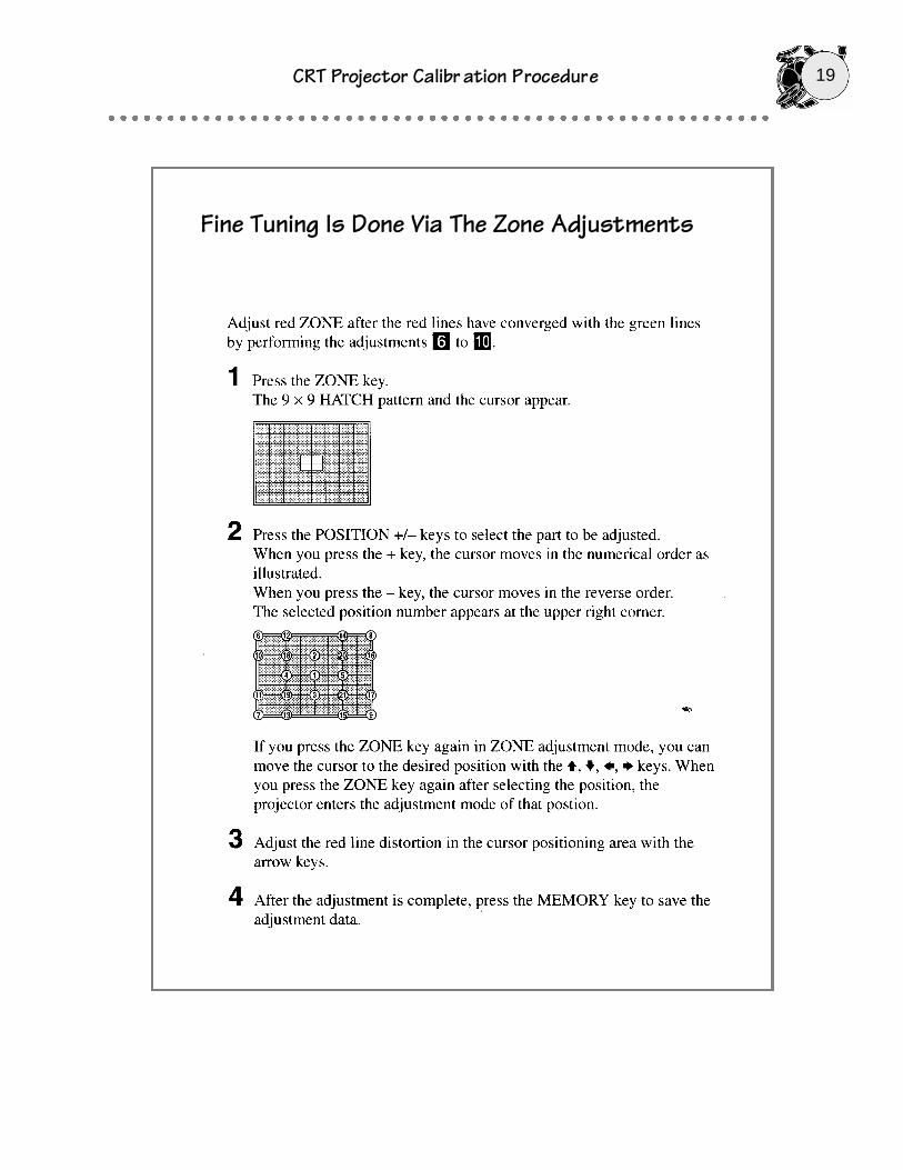
Fine Tuning Is Done Via The Zone Adjustments
20CRT Projector Calibr ation Procedure
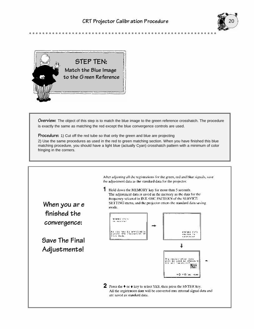
Overview: The object of this step is to match the blue image to the green reference crosshatch. The procedureis exactly the same as matching the red except the blue convergence controls are used.
Procedure: 1) Cut off the red tube so that only the green and blue are projecting 2) Use the same procedures as used in the red to green matching section. When you have finished this bluematching procedure, you should have a light blue (actually Cyan) crosshatch pattern with a minimum of colorfringing in the corners.
STEP TEN:Match the Blue Imageto the G reen Reference
When you ar efinished theconvergence:
Save The FinalAdjustments!
CRT Projector Calibr ation Procedure 21
STEP ELEVEN:Setting Up Different
Aspect Ratio Memories
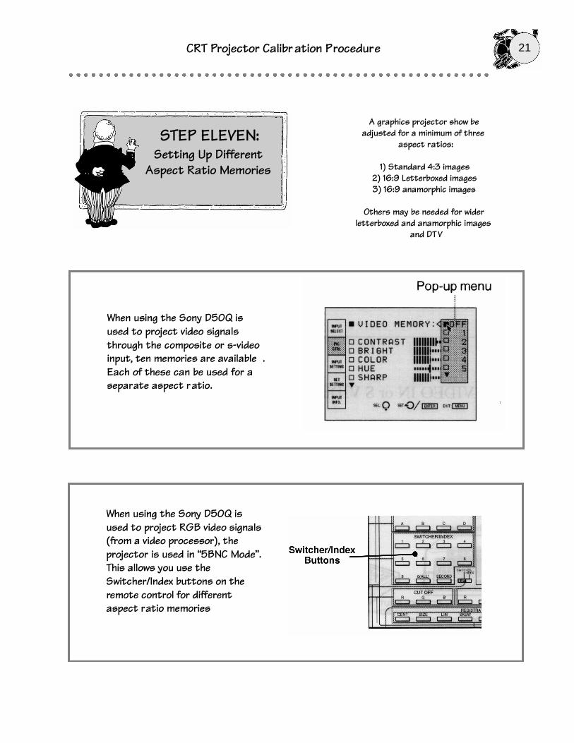
When using the Sony D50Q isused to project video signalsthrough the composite or s-videoinput, ten memories are available .Each of these can be used for aseparate aspect ratio.
A graphics projector show beadjusted for a minimum of three
aspect ratios:
1) Standard 4:3 images2) 16:9 Letterboxed images3) 16:9 anamorphic images
Others may be needed for widerletterboxed and anamorphic images
and DT V
When using the Sony D50Q isused to project RGB video signals(from a video processor), theprojector is used in “5BNC Mode”.This allows you use theSwitcher/Index buttons on theremote control for differentaspect ratio memories

22CRT Projector Calibr ation Procedure
Imagine it's a cool summer night, the stars scintillatebrilliantly in the sky overhead and the campfire is blazingaway. You've just finished a hearty meal of roast
mastodon and you, and the rest of your loinskin-clad band,are settling in for a good round of story telling. Aftereveryone quiets down, shadowy figures wearing animalmasks and draped in fur emerge from the forest and begintelling tales of adventure, bravery and sorrow. For the restof the evening barely a grunt isheard from the audience.
Today, instead of using rocks,sticks, and dead animal parts,filmmakers generally prefer to usemotion picture film and movie setsto tell their stories. What'sinteresting, though, is that whilethe technology has changed just abit, the essence of story tellingremains the same. Filmmakersstill use the best technology attheir disposal to tell their story.However, in contrast to thestorytellers of Paleolithic times,contemporary filmmakers rely ontechnology not only to create theirvision, but to reproduce it for theaudience. And they count on theA/V reproduction technologyemployed to recreate their visionintact. This is why calibration as a principle is important.Calibration of audio, video and film equipment is a way ofinsuring that the director's vision is being reproduced inexactly the way he or she intended it to be. In this articlewe will look at the calibration of video display devices inhome theaters and examine some of the tools available tocomplete the task.
Who Ya Gonna Call
Calibrating a video display requires adjusting manycontrols and it is important to know that there are twolevels of expertise involved. The first involves adjusting
user controls that are easily accessible via the remotecontrol or from the front panel of the television monitoritself. These controls generally include functions such as:brightness, contrast, color, tint, and sharpness. On somevideo displays you may find additional functions, such ascolor temperature, image centering and picture sizeadjustments (on some widescreen displays). All of thesecontrols are referred to as "user controls" for good reason;they are designed for easy access so that the user canadjust the display's image to suit his or her tastes.
The second level of adjustment involves controls that areNOT easily accessible to the user. These "factory"adjustments are either located on hidden on-screenservice menus or are physically located inside the cabinetof the display device. The reason that these controls arenot user accessible is that they are designed for use bytrained technicians during the display's manufacturingprocess and/or during any necessary repair procedures.However, as you probably surmise, adjusting some ofthese factory controls may be necessary to calibrate avideo display for best image reproduction. This presents a
dilemma - is it necessary to callan A/V professional to calibrateyour home theater display, orcan you do it yourself?
Well, it depends. Having anaudio/video professional calibrateyour display is probably the bestroute if you are unfamiliar withelectronics and video technology.A/V professionals practice the artfrequently and have oftenreceived specialized training viaprofessional seminars. Yes, itcan be expensive, from $150 to$400 for a complete job (thefactors involved are what kind ofdisplay you have, whether you awant a tune-up or an overhaul,and how far the technician has totravel), but the results can bewell worth it. On the other hand,
for those who want to save money, or just prefer to adjusttheir electronic gear themselves, there's no reason not toproceed with the display's user controls. You can calibratethese controls easily using many of the available softwarepackages.
As for the internal factory controls or service controls onhidden menus? As you probably anticipated, we've got totoss in the boilerplate about adjusting factory controls:Attention: Do-It-Yourselfers, even though factory controlscan effect the level of performance of your video display,they are hidden for good reason. They can be verycomplex to adjust and may require special instrumentation
The Imaging Science Foundationmaintains a nationwide team ofdealers and installers trained to
calibrate video displays
Video DisplayCalibration

CRT Projector Calibr ation Procedure 23
to calibrate properly (you can literally cause more harmthan good if you adjust these controls "by eye"). Also, allof today's CRT-based displays and televisions containsome pretty high voltages, and combined with the fact thatyou may cancel your factory warranty by opening up theset -Well, you get the picture.
The Calibration Tool Chest
Not to long ago, audio and video calibration procedurescould only be performed by professionals who had accessto expensive video test pattern and audio test tonegenerators. Today that situation has changed becausealmost all of the test signals needed for calibration can bereproduced in the home via laserdiscs, DVD discs andcomputer software programs. The good news for do-it-yourselfers and A/V professionals alike is that theseprograms are easily available and reasonably priced. Hereare three we recommend you look at.
Video Essentials™ - Available from the Imaging Science
Foundation (ISF), Video Essentials™ is the best knownprogram for audio and video calibration. Founded severalyears ago by industry veterans Joe Kane and Joel Silver,the ISF is one of the first organizations to promote videoquality issues in the consumer marketplace. VideoEssentials™, which the ISF offers on laserdiscs andDVDs, is a wonderfully produced program. It starts off byillustrating the need for audio and video calibration andthen runs through several well-animated technologytutorials. After the proper ground work is laid, it stepsthrough the complete setup of a home theater's audiosystem, and then a full video calibration procedure. One ofthe nice features of the Video Essentials™ disc is that italso has a large collection of excellent video clips to viewthe finished work on. The Video Essentials™ laserdiscand DVD are available for $49.95.
AVIA™ - AVIA (Audio Video Interactive Aid) is calibrationsoftware available from Ovation Software. It currently isavailable as a CDROM-based program that runs on PCs,Macs and Windows NT machines and a DVD The AVIAprogram is powerful and multifaceted. It is chock full of
VIDEO ESSENTIALS is available from theIMAGING SCIENCE FOUND ATION
3257 Harrington Dr., Boca Raton, FL33496 561-997-9073
AVIA is available from OVATION SOFT WARE
200 Putnam St., Marietta, OH 45750 614-373-6212
DISPLAYMATE is available fromSONERA TECHNOLOGIES PO Box 565, Rumson, NJ 07760 908-747-6886
Video Test Pattern Generator Audio Test Tone Generator
Ovation Software’ sAVIA program has two on-screen interactiv e
test signal gener atorsfor calibrating an
entire home theaterA/V system

24CRT Projector Calibr ation Procedure
version of the AVIA program will be available on DVD).Because AVIA is a computer program, one must have away to connect a computer to the A/V system beingcalibrated. (Note: this is commonly done with via interfacecards or scan converters). The AVIA program is powerfuland multifaceted. It is chock full of everything from highlydetailed audio/video technology tutorials to completelyinteractive test pattern generators. Of special interest tothose involved in home theater construction are twosections. One is an interactive on-screen calculator inwhich you plug in your video system specifications (size ofdisplay, aspect ratio, etc) and it calculates the properseating locations for the audience. Another is a calculatorwhich calculates and plots sound resonance modes inhome theater rooms of different dimensions. For thosewho simply want to calibrate their home theater, AVIA willstep you through the entire procedure interactively.Advanced users and professionals can skip right to twoon-screen test signal generators; one for video testpatterns, the other for audio signals. The AVIA softwareprogram is priced at $59.95 for the computer software andDVD versions.
DisplayMate™ - Sonera Technologies are the folks thatproduce the test patterns used in the famousINFOCOMM™ projector shootouts. Their DisplayMate testpattern software is very popular in the computer industry.It is used by virtually every computer publication for thetesting of computer monitors and by most manufacturersof computer display devices. Their product line currentlyconsists of four packages: DisplayMate™, DisplayMate forWindows™, DisplayMate for Windows -Video Edition™,and DisplayMate Professional™. DisplayMate forWindows -Video Edition™ (the version of interest to mosthome theater enthusiasts) is basically a ultra-talented testpattern generator. It offers 116 test patterns, many ofwhich are available nowhere else. A very handy feature isthat each of DisplayMate’s test patterns includes aninformation window that explains what the pattern is for,how it works and what effects to look for. With the
convergence of TV and PCs coming closer every day,DisplayMate is a way of assuring that the two worktogether well. DisplayMate for Windows -Video Edition™retails for $99.95.
Video Calibration, Control by Control
Video displays are remarkable complex devices. Tocalibrate them requires the adjustment of many usercontrols, and if an A/V professional is involved, theadjustment of potentially dozens of internal controls. Hereare some of the ones you should know about:
• Brightness Control. If you are a film buff you know thatmany directors thrive on dark scenes. They often haveshadowy figures appearing and disappearing into murkydarkness. It is therefore critical to have a video image'sblack level match the film release's black level or you canmiss story details. Thankfully control of the black level ofthe picture is a close as your monitor's "Brightness" or"Black Level" control. The standard pattern for adjustingblack level is PLUGE (Picture Line Up GeneratingEquipment) pattern that allows you to set the black levelproperly. The procedure is simple. Adjust thebrightness/black level control until you can just see the“darker-than-dark” bar melt into one to the next to it.
• Contrast Control. When you adjust the contrast controlon a CRT-based video display device for best peakwhites, you aren't actually calibrating the display's contrastrange; what you are doing is making sure the monitorbehaves itself. The problem is that when the user contrastcontrol is set too high, the high voltage power supply canrun out of it's linear operating range, and when thishappens bright images can lose focus and picturegeometry can shift. The standard pattern used to visualizea high voltage supply's linear range is a needle pulsepattern (see our diagram). Adjusting the contrast controlfor best peak whites with this pattern is simple. Just turnup the contrast until the pulse starts to distort. However
Adjusting thebrightness control of avideo display device is
very important forproper black levelreproduction. If
adjusted incorrectly ,important shadowdetails can be lost
from the image .
CRT Projector Calibr ation Procedure 25
don’t be surprised if your contrast control setting isn’t nearthe top of the range. Most monitors and televisions cannotdisplay a linear picture in the upper contrast ranges. If youfind this is the case with your monitor, you have threeoptions. You can reduce the ambient light in the room, youcan stack another projector (if you are using a frontprojector) or you can turn it up anyway and run it out thelinear range (Many people do this anyway).
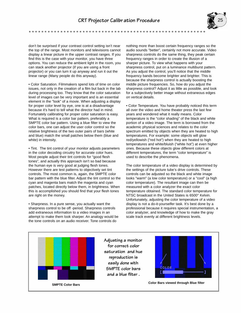
• Color Saturation. Filmmakers spend lots of time on colorissues, not only in the creation of a film but back in the labduring processing too. They know that the color saturationlevel of images can be very important and is an essentialelement in the "look" of a movie. When adjusting a displayfor proper color level by eye, one is at a disadvantagebecause it's hard to tell what the director had in mind.Fortunately calibrating for proper color saturation is easy.What is required is a color bar pattern, preferably aSMPTE color bar pattern. Using a blue filter to view thecolor bars, one can adjust the user color control so therelative brightness of the two outer pairs of bars (whiteand blue) match the small patches below them (blue andwhite) in intensity.
• Tint. The tint control of your monitor adjusts parametersin the color decoding circuitry for accurate color hues.Most people adjust their tint controls for “good fleshtones”, and actually this approach isn’t so bad becausethe human eye is very good at judging flesh tones.However there are test patterns to objectively set tintcontrols. The most common is, again, the SMPTE colorbar pattern with the blue filter. Adjust the tint control so thecyan and magenta bars match the magenta and cyanpatches, located directly below them, in brightness. Whenthis is accomplished you should find that your flesh tonesare right on the money.
• Sharpness. In a pure sense, you actually want thesharpness control to be off -period. Sharpness controlsadd extraneous information to a video images in anattempt to make them look sharper. An analogy would bethe tone controls on an audio receiver. Tone controls do
nothing more than boost certain frequency ranges so theaudio sounds "better", certainly not more accurate. Videosharpness controls do the same thing, they peak certainfrequency ranges in order to create the illusion of asharper picture. To view what happens with yoursharpness control, put on a luminance multiburst pattern.As you adjust the control, you’ll notice that the middlefrequency bands become brighter and brighter. This isbecause the sharpness control is actually boosting themiddle picture frequencies. So, how do you adjust thesharpness control? Adjust it as little as possible, and lookfor a subjectively better image without extraneous edgeson vertical details.
• Color Temperature. You have probably noticed this termall over the video and home theater press the last fewyears and wondered what it really means. Colortemperature is the “color shading” of the black and whiteportion of a video image. The term is borrowed from theacademic physical sciences and relates to the colorspectrum emitted by objects when they are heated to hightemperatures. For example: some objects will glowred/yellowish (“red hot”) when they are heated to hightemperatures and white/bluish (“white hot”) at even higherones. Because these objects glow different colors atdifferent temperatures, the term “color temperature” isused to describe the phenomena.
The color temperature of a video display is determined bythe settings of the picture tube’s drive controls. Thesecontrols can be adjusted so the black and white imagelooks "warm" (a low color temperature) or a "cool" (a highcolor temperature). The resultant image can then bemeasured with a color analyzer the exact colortemperature obtained. The standard color temperature forNTSC broadcast in the United States is 6500° Kelvin.Unfortunately, adjusting the color temperature of a videodisplay is not a do-it-yourselfer task. It’s best done by aprofessional because it requires special instrumentation, acolor analyzer, and knowledge of how to make the grayscale track evenly at different brightness levels.
Adjusting a monitorfor correct color
saturation and huereproduction iseasily done with
SMPTE color barsand a blue filter .
Color Bars viewed through Blue filterSMPTE Color Bars
26CRT Projector Calibr ation Procedure
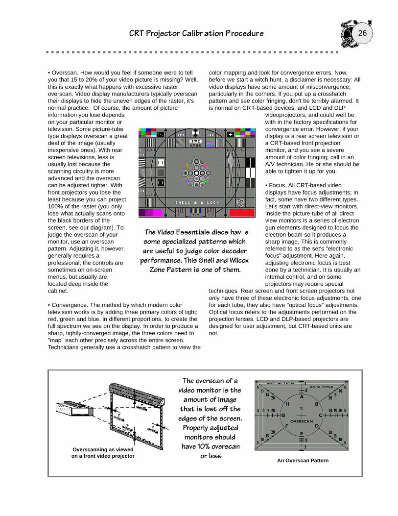
• Overscan. How would you feel if someone were to tellyou that 15 to 20% of your video picture is missing? Well,this is exactly what happens with excessive rasteroverscan. Video display manufacturers typically overscantheir displays to hide the uneven edges of the raster, it’snormal practice. Of course, the amount of pictureinformation you lose dependson your particular monitor ortelevision. Some picture-tubetype displays overscan a greatdeal of the image (usuallyinexpensive ones). With rearscreen televisions, less isusually lost because thescanning circuitry is moreadvanced and the overscancan be adjusted tighter. Withfront projectors you lose theleast because you can project100% of the raster (you onlylose what actually scans ontothe black borders of thescreen, see our diagram). Tojudge the overscan of yourmonitor, use an overscanpattern. Adjusting it, however,generally requires aprofessional; the controls aresometimes on on-screenmenus, but usually arelocated deep inside thecabinet.
• Convergence. The method by which modern colortelevision works is by adding three primary colors of light;red, green and blue, in different proportions, to create thefull spectrum we see on the display. In order to produce asharp, tightly-converged image, the three colors need to"map" each other precisely across the entire screen.Technicians generally use a crosshatch pattern to view the
color mapping and look for convergence errors. Now,before we start a witch hunt, a disclaimer is necessary: Allvideo displays have some amount of misconvergence;particularly in the corners. If you put up a crosshatchpattern and see color fringing, don't be terribly alarmed. Itis normal on CRT-based devices, and LCD and DLP
videoprojectors, and could well bewith in the factory specifications forconvergence error. However, if yourdisplay is a rear screen television ora CRT-based front projectionmonitor, and you see a severeamount of color fringing; call in anA/V technician. He or she should beable to tighten it up for you.
• Focus. All CRT-based videodisplays have focus adjustments; infact, some have two different types.Let's start with direct-view monitors.Inside the picture tube of all directview monitors is a series of electrongun elements designed to focus theelectron beam so it produces asharp image. This is commonlyreferred to as the set's "electronicfocus" adjustment. Here again,adjusting electronic focus is bestdone by a technician. It is usually aninternal control, and on someprojectors may require special
techniques. Rear screen and front screen projectors notonly have three of these electronic focus adjustments, onefor each tube, they also have "optical focus" adjustments.Optical focus refers to the adjustments performed on theprojection lenses. LCD and DLP-based projectors aredesigned for user adjustment, but CRT-based units arenot.
The Video Essentials discs hav esome specialized patterns whichare useful to judge color decoder
performance. This Snell and WilcoxZone Pattern is one of them.
The overscan of avideo monitor is the
amount of imagethat is lost off theedges of the screen.
Properly adjustedmonitors should
have 10% overscanor less
Overscanning as viewedon a front video projector
An Overscan Pattern
CRT Projector Calibr ation Procedure 27
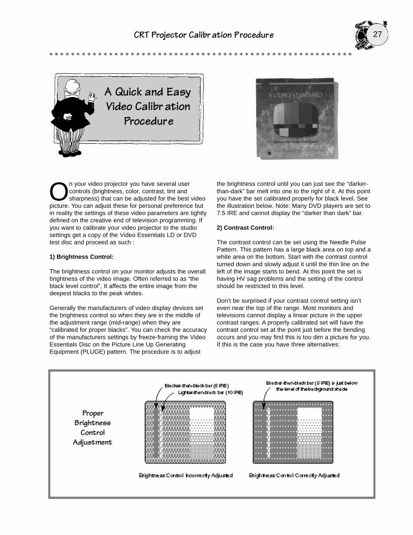
On your video projector you have several usercontrols (brightness, color, contrast, tint andsharpness) that can be adjusted for the best video
picture. You can adjust these for personal preference butin reality the settings of these video parameters are tightlydefined on the creative end of television programming. Ifyou want to calibrate your video projector to the studiosettings get a copy of the Video Essentials LD or DVDtest disc and proceed as such :
1) Brightness Control:
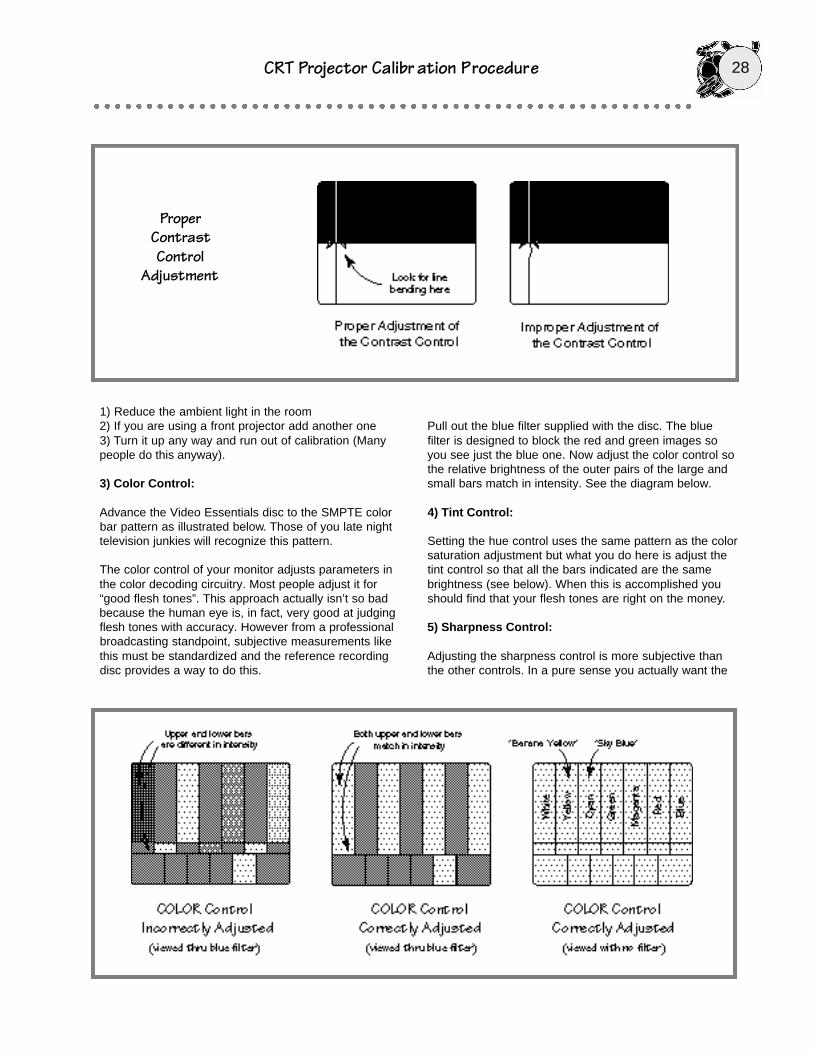
The brightness control on your monitor adjusts the overallbrightness of the video image. Often referred to as “theblack level control”, It affects the entire image from thedeepest blacks to the peak whites.
Generally the manufacturers of video display devices setthe brightness control so when they are in the middle ofthe adjustment range (mid-range) when they are“calibrated for proper blacks”. You can check the accuracyof the manufacturers settings by freeze-framing the VideoEssentials Disc on the Picture Line Up GeneratingEquipment (PLUGE) pattern. The procedure is to adjust
the brightness control until you can just see the “darker-than-dark” bar melt into one to the right of it. At this pointyou have the set calibrated properly for black level. Seethe illustration below. Note: Many DVD players are set to7.5 IRE and cannot display the “darker than dark” bar.
2) Contrast Control:
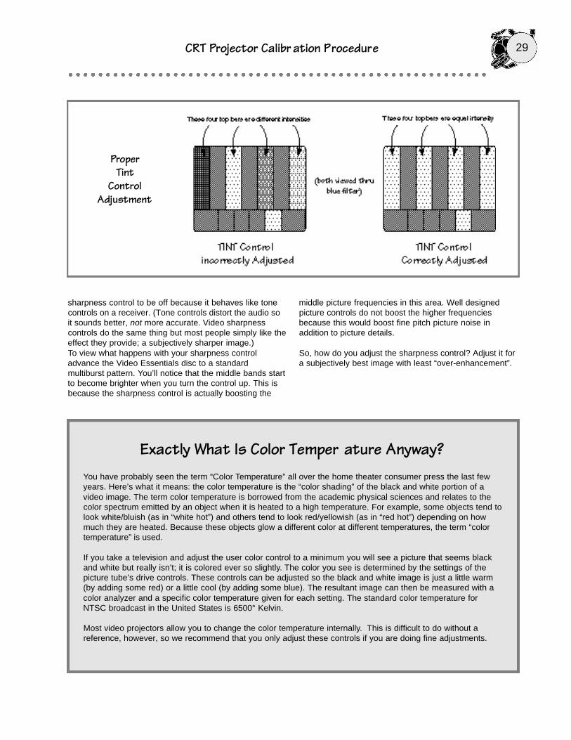
The contrast control can be set using the Needle PulsePattern. This pattern has a large black area on top and awhite area on the bottom. Start with the contrast controlturned down and slowly adjust it until the thin line on theleft of the image starts to bend. At this point the set ishaving HV sag problems and the setting of the controlshould be restricted to this level.
Don’t be surprised if your contrast control setting isn’teven near the top of the range. Most monitors andtelevisions cannot display a linear picture in the uppercontrast ranges. A properly calibrated set will have thecontrast control set at the point just before the bendingoccurs and you may find this is too dim a picture for you.If this is the case you have three alternatives:
A Quick and Easy Video Calibr ation
Procedure
ProperBrightness
ControlAdjustment
28CRT Projector Calibr ation Procedure
ProperContrastControl
Adjustment
1) Reduce the ambient light in the room2) If you are using a front projector add another one3) Turn it up any way and run out of calibration (Manypeople do this anyway).
3) Color Control:
Advance the Video Essentials disc to the SMPTE colorbar pattern as illustrated below. Those of you late nighttelevision junkies will recognize this pattern.
The color control of your monitor adjusts parameters inthe color decoding circuitry. Most people adjust it for“good flesh tones”. This approach actually isn’t so badbecause the human eye is, in fact, very good at judgingflesh tones with accuracy. However from a professionalbroadcasting standpoint, subjective measurements likethis must be standardized and the reference recordingdisc provides a way to do this.
Pull out the blue filter supplied with the disc. The bluefilter is designed to block the red and green images soyou see just the blue one. Now adjust the color control sothe relative brightness of the outer pairs of the large andsmall bars match in intensity. See the diagram below.
4) Tint Control:
Setting the hue control uses the same pattern as the colorsaturation adjustment but what you do here is adjust thetint control so that all the bars indicated are the samebrightness (see below). When this is accomplished youshould find that your flesh tones are right on the money.
5) Sharpness Control:
Adjusting the sharpness control is more subjective thanthe other controls. In a pure sense you actually want the
CRT Projector Calibr ation Procedure 29
sharpness control to be off because it behaves like tonecontrols on a receiver. (Tone controls distort the audio soit sounds better, not more accurate. Video sharpnesscontrols do the same thing but most people simply like theeffect they provide; a subjectively sharper image.)To view what happens with your sharpness controladvance the Video Essentials disc to a standardmultiburst pattern. You’ll notice that the middle bands startto become brighter when you turn the control up. This isbecause the sharpness control is actually boosting the
middle picture frequencies in this area. Well designedpicture controls do not boost the higher frequenciesbecause this would boost fine pitch picture noise inaddition to picture details.
So, how do you adjust the sharpness control? Adjust it fora subjectively best image with least “over-enhancement”.
ProperTint
ControlAdjustment
Exactly What Is Color Temper ature Anyway?You have probably seen the term “Color Temperature” all over the home theater consumer press the last fewyears. Here’s what it means: the color temperature is the “color shading” of the black and white portion of avideo image. The term color temperature is borrowed from the academic physical sciences and relates to thecolor spectrum emitted by an object when it is heated to a high temperature. For example, some objects tend tolook white/bluish (as in “white hot”) and others tend to look red/yellowish (as in “red hot”) depending on howmuch they are heated. Because these objects glow a different color at different temperatures, the term “colortemperature” is used.
If you take a television and adjust the user color control to a minimum you will see a picture that seems blackand white but really isn’t; it is colored ever so slightly. The color you see is determined by the settings of thepicture tube’s drive controls. These controls can be adjusted so the black and white image is just a little warm(by adding some red) or a little cool (by adding some blue). The resultant image can then be measured with acolor analyzer and a specific color temperature given for each setting. The standard color temperature forNTSC broadcast in the United States is 6500° Kelvin.
Most video projectors allow you to change the color temperature internally. This is difficult to do without areference, however, so we recommend that you only adjust these controls if you are doing fine adjustments.

30CRT Projector Calibr ation Procedure
Adjusting TheColor Balance OnThe Sony D50Q
SONY VPH-D50Q

CRT Projector Calibr ation Procedure 31

32CRT Projector Calibr ation Procedure
NOTES: