cross-flow-induced-vibrations in heat exchanger tube ... · induced vibration due to shell side...
TRANSCRIPT

4
Cross-Flow-Induced-Vibrations in Heat Exchanger Tube Bundles: A Review
Shahab Khushnood et al.* University of Engineering & Technology, Taxila
Pakistan
1. Introduction
Over the past few decades, the utility industry has suffered enormous financial losses
because of vibration related problems in steam generators and heat exchangers. Cross-flow
induced vibration due to shell side fluid flow around the tubes bundle of shell and tube heat
exchanger results in tube vibration. This is a major concern of designers, process engineers
and operators, leading to large amplitude motion or large eccentricities of the tubes in their
loose supports, resulting in mechanical damage in the form of tube fretting wear, baffle
damage, tube collision damage, tube joint leakage or fatigue and creep etc.
Most of the heat exchangers used in nuclear, petrochemical and power generation industries
are shell and tube type. In these heat exchangers, tubes in a bundle are usually the most
flexible components of the assembly. Because of cross-flow, tubes in a bundle vibrate. The
general trend in heat exchanger design is towards larger exchangers with increased shell
side velocities, to cater for the required heat transfer capacity, improve heat transfer and
reduce fouling effects. Tube vibrations have resulted in failure due to mechanical wear,
fretting and fatigue cracking. Costly plant shutdowns have lead to research efforts and
analysis for flow- induced vibrations in cross-flow of shell side fluid. The risk of radiation
exposure in steam generators used in pressurized water reactor (PWR) plants demand
ultimate safety in designing and operating these exchangers.
(Erskine & Waddington, 1973) have carried out a parametric form of investigation on a total
of nineteen exchanger failures, in addition to other exchangers containing no failures. They
realized that these failures represent only a small sample of the many exchangers currently
in service. The heat exchanger tube vibration workshop (Chenoweth, 1976) pointed out a
critical problem i.e., the information on flow-induced vibration had mostly been withheld
because of its proprietary nature.
* Zaffar Muhammad Khan1, Muhammad Afzaal Malik2, Zafarullah Koreshi2, Muhammad Akram Javaid1, Mahmood Anwer Khan3, Arshad Hussain Qureshi4, Luqman Ahmad Nizam1, Khawaja Sajid Bashir1, Syed Zahid Hussain1 1University of Engineering & Technology, Taxila, Pakistan 2Air University, Islamabad Pakistan 3College of Electrical & Mechanical Engineering NUST, Rawalpindi, Pakistan 4University of Engineering & Technology, Lahore, Pakistan
www.intechopen.com

Nuclear Power Plants 72
Failure of heat exchanger tubes in a bundle due to flow-induced vibrations is a deep concern, particularly in geometrically large and highly rated units. Excessive tube vibration may cause failure by fatigue or by fretting wear. Each tube in a bundle is loosely supported at baffles, forming multiple supports often with unequal support spacing. Reactor components like heat exchanger tubes, fuel rods and piping sections may be modeled as beams on multiple supports. It is important to determine whether any of the natural frequencies be within the operating range of frequencies. Considerable research efforts have been carried out, which highlight the importance of the problem.
Tube natural frequency is an important and primary consideration in flow-induced vibration design. A considerable research has been carried out to calculate the natural frequencies of straight and curved (U-tubes) by various models for single and multiple, continuous spans, in air and in liquids for varying end and intermediate support conditions. (Chenoweth, 1976), (Chen & Wambsganss, 1974), (Shin & Wambsganss,1975), (Wambsganss, et al., 1974), (Weaver, 1993), (Brothman, et al., 1974), (Lowery & Moretti, 1975), (Elliott & Pick, 1973), (Jones, 1970), (Ojalvo & Newman, 1964) and (Khushnood et al., 2002), to name some who have carried out research and highlighted the importance of the calculation of natural frequencies of heat exchanger tubes in a bundle.
The dimensionless parameters required for modeling a system may be determined as follows (Weaver, 1993):
Through non-dimensionalizing the differential equations governing the system behavior.
From application of Buckingham Pi-theorem.
This theorem only gives the number of s , and not a calculation procedure. So we rely
on (i) essentially.
(Shin & Wambsganss, 1975), and (Khushnood et al., 2000) gave the basics of model testing via dimensional analysis. (Blevins, 1977) has described non-dimensional variables such as geometry, reduced velocity, dimensionless amplitude, mass ratio, Reynolds number and damping factor as being useful in describing the vibrations of an elastic structure in a subsonic steady flow. However, other non-dimensional variables such as Mach number, capillary number, Richardson number, Strouhal number and Euler number are also useful in case effects such as surface tension, gravity, supersonic flow or vortex shedding are also considered.
It is generally accepted that the tube bundle excitation mechanisms are (Weaver, 1993, Pettigrew et al., 1991)
Turbulent buffeting
Vorticity excitation
Fluid-elastic excitation
Acoustic resonance
Turbulent buffeting cannot be avoided in heat exchangers, as significant turbulence levels are always present. Vibration at or near shedding frequency has a strong organizing effect on the wake. Vorticity or vortex shedding or periodic wake shedding is a discrete, periodic, and a constant Strouhal number phenomenon. Strouhal number is the proportionality constant between the frequency of vortex shedding and free stream velocity divided by
www.intechopen.com

Cross-Flow-Induced-Vibrations in Heat Exchanger Tube Bundles: A Review 73
cylinder width. Fluid-elastic instability is by far the most dangerous excitation mechanism and the most common cause of tube failure. This instability is typical of self-excited vibration in that it results from the interaction of tube motion and flow. Acoustic resonance is caused by some flow excitation (possibly vortex shedding) having a frequency, which coincides with the natural frequency of the heat exchanger cavity.
With regard to dynamic parameters, including added mass and damping, the concept of added mass was first introduced by DuBuat in 1776 (Weaver, 1993). The fluid oscillating with the tube may have an appreciable affect on both natural frequency and mode shape. Added mass is a function of geometry, density of fluid and the size of the tube (Moretti & Lowry, 1976). Several studies including (Weaver, 1993, Lowery, 1995, Jones, 1970, Chen et al., 1994, Taylor et al., 1998, Rogers et al., 1984, Noghrehkar et al., 1995, Carlucci, 1980, Pettigrew et al., 1994, Pettigrew et al., 1986, Zhou et al., 1997) have targeted damping in heat exchanger tube bundles in single-phase and two-phase cross-flow. (Rogers et al., 1984) have given identification of seven separate sources of damping.
(Ojalvo & Newman, 1964) have presented design for out-of-plane and in-plane frequency
factors for various modes. (Jones, 1970) carried out experimental and analytical analysis of a
vibrating beam immersed in a fluid and carrying concentrated mass and rotary inertia.
(Erskine & Waddington, 1973) conducted parametric form of investigation on a total of 19
exchanger failures along with other exchangers containing no failures, for comparative
purpose, indicated the incompleteness of methods available till then and emphasized the
need for a fully comprehensive design method. Finite element technique applied by (Elliott
& Pick, 1973), concluded that the prediction of natural frequencies was possible with this
method and that catastrophic vibrations might be prevented by avoiding matching of
material and excitation frequencies. Lack of sufficient data to support comprehensive
analytical description for several fundamentally different vibration excitation mechanisms
for tube vibration have been indicated in Ontario Hydro Research Division Report (Simpson
& Hartlen, 1974). The report also gives response in terms of mid-span amplitude to a
uniformly distributed lift for a simply supported tube. A simple graphical method for
predicting the in-plane and out-of-plane frequencies of continuous beams and curved beams
on periodic, multiple supports with spans of equal length have been presented by (Chen &
Wambsganss, 1974). They have given design guidelines for calculating natural frequencies
of straight and curved beams. (Wambsganss, et al., 1974) have carried out an analytical and
experimental study of cylindrical rod vibrating in a viscous fluid, enclosed by a rigid,
concentric cylindrical shell, obtaining closed-form solution for added mass and damping
coefficient. (Shin & Wambsganss, 1975) have given information for making the best possible
evaluation of potential flow-induced vibration in LMFBR steam generator focusing on tube
vibration. A simple computer program developed by (Lowery & Moretti, 1975), calculates
frequencies of idealized support with multiple spans. (Chenoweth, 1976), in his final report
on heat exchanger tube vibration, pointed out the slow progress and inadequacy of existing
methods and a need for field data to test suitability of design procedures. It stressed the
need for testing specially built and instrumented industrial- sized heat exchangers and wind
tunnel based theories to demonstrate interaction of many parameters that contribute to
flow-induced vibrations. (Rogers et al., 1984) have modeled mass and damping effects of
surrounding fluid and also the effects of squeeze film damping. (Pettigrew et.al., 1986) have
treated damping of multi-span heat exchanger tubes in air and gases in terms of different
www.intechopen.com

Nuclear Power Plants 74
energy dissipation mechanisms, showing a strong relation of damping to tube support
thickness.
(Price, 1995) has reviewed all known theoretical models of fluid-elastic instability for cylinder arrays subject to cross-flow with particular emphasis on the physics of instability mechanisms. Despite considerable difference in the theoretical models, there has been a general agreement in conclusions. (Masatoshi et al., 1997) have carried tests on an intermediate heat exchanger with helically coiled tube bundle using a partial model to investigate the complicated vibrational behavior induced by interaction through seismic stop between center pipe and tube bundle. They have indicated the effect of the size of gap between seismic stop and tube support of the bundle.(Botros & Price, 2000) have carried out a study of a large heat exchanger tube bundle of styrene monomer plant, which experienced severe fretting and leaking of tubes and considerable costs associated with operational shutdowns. Analysis through Computational Fluid Dynamics (CFD) and fluid-elastic instability study resulted in the replacement of a bundle with shorter span between baffles, and showed no signature of vibration over a wide range of frequencies. (Yang, 2000) has postulated that crossing-frequency can be used as a measure of heat exchanger support plate effectiveness. Crossing-frequency is the number of times per second the vibrational amplitude crosses the zero displacement line from negative displacement to positive displacement.
The wear of tube due to non-linear tube-to-tube support plate (TSP) interactions is caused by the gap clearances between the two interacting components. Tube wall thickness loss and normal work-rates for different TSP combination studies have been the target. Electric Power Research Institute (EPRI), launched an extensive program in early 1980's for analyses of fluid forcing functions, software development and studying linear and non-linear tube bundle dynamics. Other studies include (Rao et al., 1988), (Axisa & Izquierdo, 1992), (Payen et al., 1995), (Peterka, 1995), (Hassan et al., 2000), (Charpentier and Payen, 2000) and (Au-Yang, 1998).
Generally, there are three geometric configurations in which tubes are arranged in a bundle. These are triangular, normal square and rotated square. Relatively little information exists on two-phase cross-flow induced vibration. Not surprisingly as single-phase flow-induced vibration is not yet fully understood. Vibration in two-phase is much more complex because it depends upon two-phase flow regime and involves an important consideration, the void fraction, which is the ratio of volume of gas to the volume of the liquid gas mixture. Two-phase flow experimentation is much more expensive and difficult to carry out usually requiring pressurized loops with the ability to produce two-phase mixtures of desired void fractions.
Two-phase flow research includes the models, such as, Smith Correlation (Smith, 1968), drift-flux model developed by (Zuber and Findlay, 1965), Schrage correlation (Schrage, 1988), and Feenstra model (Feentra et al., 2000). (Frick et al., 1984) has given an overview of tube wear-rate in two-phase flow. (Pettigrew et al., 2000), (Mirza & Gorman, 1973), (Taylor et al.,1989), (Papp, 1988), (Wambsganss et al., 1992) and others have carried out potential research for vibration response. Earlier reviews on two-phase cross flow are provided by (Paidoussis, 1982), (Weaver & Fitzpatrik, 1988), (Price, 1995), and (Pettigrew & Taylor, 1994).
Two-phase cross-flow induced vibration in tube bundles of process heat exchangers and U-bend region of nuclear steam generators can cause serious tube failures by fatigue and fretting wear. Tube failures could force entire plant to shut down for costly repairs and suffering loss of production. Vibration problems may be avoided by thorough vibration
www.intechopen.com

Cross-Flow-Induced-Vibrations in Heat Exchanger Tube Bundles: A Review 75
analysis. However, this requires an understanding of vibration excitation and damping mechanism in two-phase flow. A number of flow regimes (Table 1) can occur for a given boundary configuration, depending upon the concentration and size of the gas bubbles and on the mass flow rates of the two-phases. Two-phase (khushnood, et al., 2004) flow characteristics greatly depend upon the type of flow occurring.
Flow Type
Average Void Fraction
Specification
Bubble ~0.3 Some bubbles are present in liquid flow and move with the same velocity.
Slug 0.3-0.5 Liquid slugs flow intermittently.
Froth 0.5-0.8 More violent intermittent flow.
Annular 0.8-0.9 Mainly gas flow. Liquid adheres to the tube surface.
Mist ~0.9 Almost gas flow. Mist sometimes causes energy dissipation.
Table 1. Types of Flow in Two-Phases (khushnood, et al., 2004)
Vibration of tube in two-phase flow displays different flow regimes i.e., gas and liquid
phase distributions, depending upon the void fraction and mass flux. It is known that four
mechanisms are responsible for the excitation of tube arrays in cross-flow (Pettigrew, et al.,
1991). These mechanisms are: turbulence buffeting, vortex shedding or Strouhal periodicity,
fluid-elastic instability and acoustic resonance. Table 2 presents a summary of these
vibration mechanisms for single cylinder and tube bundles for liquid, gas and liquid-gas
two-phase flow respectively. Of these four mechanisms, fluid-elastic instability is the most
damaging in the short term, because it causes the tubes to vibrate excessively, leading to
rapid wear at the tube supports. This mechanism occurs once the flow rate exceeds a
threshold velocity at which tubes become self-excited and the vibration amplitude rises
rapidly with an increase in flow velocity.
Flow Situation (Cross-Flow)
Fluid-Elastic Instability
Periodic Shedding
Turbulence Excitation
Acoustic Resonance
Single Cylinder
Liquid ° * * °
Gas ° °
Two-phase ° ° * °
Tube Bundle
Liquid * °
Gas * ° *
Two-phase * ° * °
Unlikely °
Possible Most Important *
Table 2. Vibration Excitation Mechanisms (Pettigrew, et al., 1991)
www.intechopen.com

Nuclear Power Plants 76
Typically, researchers have relied on the Homogeneous Equilibrium Model (HEM) (Feentra
et al., 2000) to define important fluid parameters in two-phase flow, such as density, void
fraction and velocity. This model treats the two-phase flow as a finely mixed and
homogeneous in density and temperature, with no difference in velocity between the gas
and liquid phases. This model has been used a great deal because it is easy to implement
and is widely recognized which facilitated earlier data comparison. Other models include
Smith correlation (Smith, 1968), drift-flux model developed by (Zuber and Findlay, 1965),
Schrage Correlation (Schrage, 1988), which is based on empirical data, and Feenstra model
(Feentra et al., 2000), which is given in terms of dimensionless numbers.
Dynamic parameters such as added or hydrodynamic mass and damping are very
important considerations in two-phase cross-flow induced vibrations. Hydrodynamic
mass depends upon pitch-to-diameter ratio and decrease with increase in void fraction.
Damping is very complicated in two-phase flow and is highly void fraction dependent.
Tube-to-restraint interaction at the baffles (loose supports) can lead to fretting wear
because of out of plane impact force and in-plane rubbing force. (Frick et al., 1984) has
given an overview of the development of relationship between work-rate and wear-rate.
Another important consideration in two-phase flow is the random turbulence excitation.
Vibration response below fluid-elastic instability is attributed to random turbulence
excitation.
(Pettigrew et al., 2000), (Mirza & Gorman, 1973), (Taylor et al.,1989), (Papp, 1988), and
(Wambsganss et al., 1992) to name some, have carried out research for Root Mean Square
(RMS) vibration response, encompassing spatially correlated forces, Normalized Power
Spectral Density (NPSD), two-phase flow pressure drop, two-phase friction multiplier, mass
flux, and coefficient of interaction between fluid mixture and tubes. More recently
researchers have expanded the study to two-phase flow which occur in nuclear steam
generators and many other tubular heat exchangers, a review of which was last given by
(Pettigrew & Taylor, 1994). A current review on this topic is given by (Khushnood et al.,
2004)
The use of Finite Element Method (FEM), Computational Fluid Dynamics (CFD) and Large
Eddy Simulation (LES) have proved quite useful in analyzing flow-induced vibrations in
tube bundles in recent years. Earlier on, only pressure drop and heat transfer calculations
were considered as the basis of heat exchanger design. Recently, flow-induced tube
vibrations have also been included in the design criteria for process heat exchangers and
steam generators.
1.1 Regimes
(Kim et al., 2009) have carried flow induced vibrations (Experimental study of two circular
cylinders in tandem arrangement) and examined three different experimental conditions
both cylinders allowed to vibrate, the upstream cylinder is allowed to vibrate with the
downstream cylinder fixed and downstream cylinder allowed to vibrate with upstream
cylinder fixed. The results include five regimes depending upon 詣 経斑 , fluctuating lift forces
and vibration characteristics of the cylinder as given in Table 3.
www.intechopen.com

Cross-Flow-Induced-Vibrations in Heat Exchanger Tube Bundles: A Review 77
Regimes I II III IV V
Range 0.1 ≤鯖 拶斑
≥ 0.2
0.2 ≤鯖 拶斑 ≥
0.6
0.6 ≤鯖 拶斑 ≥
2.0
2.0 ≤鯖 拶斑 ≥
2.7鯖 拶斑 ≥ 2.7
Response Vibration
absent
Violent vibrations
of both For 戟追 > 6
Convergent vibrations at 戟追 ≈ 6.7
Vibration absent
Each vibrating like isolated
cylinder at 戟追 ≈ 6.7
Characteristics
Vibration amplitude is strongly dependant on whether upstream cylinder is fixed or vibrating
Upstream cylinder vibration is completely suppressed when downstream cylinder is fixed but the downstream cylinder is independent of upstream cylinder.
Downstream vibration is strongly dependant on upstream cylinder but upstream cylinder vibrations is insensitive to downstream cylinder.
Table 3. Regimes of vibration for Circular cylinders tandem (Kim, et al., 2009)
2. Excitation mechanisms
2.1 Fluid-elastic instability
Fluid-elastic instability is by far the most dangerous excitation mechanism in heat exchanger tube bundles and the most common cause of tube failures. The forces associated with fluid- elastic instability exist only because of the motion of the body. (Price, 1995) has presented comprehensive review on fluid-elastic instability of cylinder arrays in cross-flow. According to Price, the nature of fluid-elastic instability can be illustrated as a feedback mechanism between structural motion and the resulting fluid forces. A small structural displacement due to turbulence alters the flow pattern, inducing a change in fluid forces. This in turn leads to a further displacement, and so on. If the displacement increases (positive feedback), then fluid-elastic instability occurs. Three mechanisms (Price, 1995), which enable the cylinder to extract energy from flow:
require a phase difference between cylinder displacement and fluid force generated.
relies on there being at least two-degrees of freedom with a phase difference between them.
because of non-linearities, the fluid force is hysteretic and its magnitude depends on the direction of cylinder motion.
A considerable theoretical and experimental research has been undertaken in the past three decades to arrive at a safe and reliable design criteria against fluid-elastic instability. The topic has been reviewed on regular basis from time to time by various researchers including (Paidoussis, 1980, 1981, 1987, 1987), (Chen, 1984, 1987, 1987, 1989), (Zukauskas et al., 1987), (Weaver & FitzPatrick, 1988), (Moretti, 1993) and (Price, 1995).
www.intechopen.com

Nuclear Power Plants 78
2.2 Fluid-elastic instability models
2.2.1 Jet switch model
(Roberts, 1962, 1966) considered both a single and a double row of cylinders normal to flow. His analysis was limited to in-flow motion (experiments indicated that instability was purely in the in-flow direction). Roberts assumed that the flow downstream of two-adjacent cylinders could be represented by two wake regions, one large and one small, and a jet between them as shown in Figure 1.
Jet
Large Wake
Imaginary Boundary
Small Wake
Entrainment
Entrainment
V Vg
ImaginaryBoundary
Upstream Cylinder
Downstream Cylinder
Fig. 1. Idealized model of the jet-flow between two cylinders in a staggered row of cylinders (Roberts, 1962).
Considering a downstream cylinder moving upstream; as the two cylinders cross, insufficient fluid flows in to the large wake region to maintain the entrainment, causing the wake to shrink and the jet to switch directions. Roberts has given the flow equation of motion for a cylinder or tube in a row.
2 2
2 22 0.717 1 ( , 2 1
2
npb pb
meann
Dd x dx V dxx C x C
d V dd m
(1)
where pbC is the base pressure coefficient, is non-dimensional time nt , D is the tube diameter, n is the natural frequency, x is the in-flow cylinder displacement, is the damping factor or ratio, is the logarithmic decrement, and m is mass of the tube. Equation 1 was solved using the method of Krylov and Bogoliubov (Minorsky, 1947) giving
cV , the velocity just sufficient to initiate limit cycle motion for any 2/m D . Neglecting unsteady terms and fluid damping, the solution reduces to
0.5
2c
n
V mK
D D
(2)
where is the ratio of fluid-elastic frequency to structural frequency, which is approximately 1.0 and is the fluid density. This has the same form as the classical Connors equation (Blevins, 1979). Figure 2 presents Robert's experimental data for pitch-to-dia. ratio ( / 1.5P D ), showing a good agreement with this theoretical model.
www.intechopen.com

Cross-Flow-Induced-Vibrations in Heat Exchanger Tube Bundles: A Review 79
___ Solution including time for jet reversal and aerodynamic damping - - - Solution assuming instantaneous jet reversal but still including aerodynamic damping ___ Solution assuming instantaneous jet reversal and neglecting aerodynamic damping Roberts' experimental results
Fig. 2. Theoretical stability boundary for fluid-elastic instability obtained by Roberts for a single flexible cylinder in a row of cylinders (Roberts, 1966).
2.2.2 Quasi-static models
Using a quasi-static analysis, (Connors & Parrondo, 1970) and later (Dalton & Helfinstine,
1971) developed the fluid-elastic instability prediction for cylinders (single row of cylinders)
subjected to cross-flow. Connors measured the fluid forces instead of predicting these using
pitch to dia. ratio of P/D=1.41. He observed many different model patterns at instability, but
suggested that the most dominant was elliptical motion (whirling). Using the measured
fluid stiffness, Connors obtained energy balances in the in-and cross-flow directions, which
must be satisfied simultaneously giving
0.5
2
pc
n
V mK
f D D
(3)
where K is the so-called Connors constant, nf is the frequency of oscillation. pcV is the so-called pitch velocity given by
pc
VPV
P D (4)
where P being the centre-to-centre inter cylinder pitch
(Blevins, 1974) has derived Equation 3 by assuming that the fluid forces on any cylinder are
due to relative displacements between itself and its neighboring cylinders. Later, (Blevins,
1979) modified his original analysis to account for flow dependent fluid damping giving
Vc /ε
ωnD
mδ/ρD2
www.intechopen.com

Nuclear Power Plants 80
1/2
1/2
22 ( )
pcx y
n
V mK
f D D
(5)
where x and y are total damping factors in the in-and cross-flow directions.
2.2.3 In viscid model
Despite the obviously viscous nature of the interstitial flow through arrays of cylinders,
the compactness of some arrays suggests that the cylinder wake regions are small,
especially for normal triangular arrays with small P/D (Price, 1995). Hence under this
assumption wake regions are neglected and flow is treated as inviscid. Many solutions
based upon potential flow theory have been given, including (Dalton & Helfinstine, 1971),
(Dalton, 1980), (Balsa, 1977), (Paidoussis et al., 1984), (Vander Hoogt & Van Compen,
1984) and (Delaigue & Planchard, 1986). The results obtained from potential flow analyses
are somewhat discouraging (Price, 1995). Recent flow visualizations suggest that even
though the wake regions are small, the interstitial flow is more complex than that
accounted for in these analyses.
2.2.4 Unsteady models
The unsteady models measure the unsteady forces on the oscillating cylinder directly.
(Tanaka & Takahara, 1980, 1981) and (Chen, 1983) have given theoretical stability boundary
for fluid-elastic instability as shown in Figures 3 and 4 respectively.
1
1
10
100
1000
10 102
103
104
2Dm
DfV npc
____ =0.01
– – – =0.03
Fig. 3. Theoretical stability boundary for fluid-elastic instability for an in-line square array, P/D=1.33, obtained by (Tanaka & Takahara, 1980, 1981).
www.intechopen.com

Cross-Flow-Induced-Vibrations in Heat Exchanger Tube Bundles: A Review 81
– – –Theoretical solution showing multiple instability boundaries ____Practical stability boundary
Fig. 4. Theoretical stability for fluid-elastic instability predicted by (Chen, 1983), for a row of cylinders with P/D=1.33.
2.2.5 Semi-analytical model
Out of many semi analytical models, Figure 5 shows theoretical stability boundary for fluid-elastic instability obtained by (Lever & Weaver, 1986).
100
0.01
1
10
0.1 1
Unstable
Unstable
Stable
1000
10 102
103
2Dm
DfV npc
– – –Theoretical solution showing multiple instability boundaries ____Practical stability boundary
Fig. 5. Theoretical stability boundary for fluid-elastic instability obtained by (Lever & Weaver, 1986) for single flexible cylinder in a parallel triangular array with P/D=1.375.
1
0.01
10
1000
100
100.1 1
Unstable
Unstable
Stable
102
2Dm ρδ
D f V npc
www.intechopen.com

Nuclear Power Plants 82
2.2.6 Quasi-steady model
(Price, 1995) remarks that Fung and Blevins have concluded that quasi-steady fluid
dynamics is valid provided 10n
V
f D; however, experiments by Price, Paidoussis and
Sychterz and others suggest that for closely spaced bodies the restriction on the use of quasi-steady fluid dynamics is much more severe than that suggested by Fung or Blevins. (Gross, 1975) carried out first quasi-steady analysis of cylinder arrays subjected to cross-flow concluding that instability in cylinder arrays is due to two distinct mechanisms: negative damping and stiffness controlled instability.
2.2.7 Computational fluid dynamic (CFD) models
The CFD solutions applicable to fluid-elastic instability and other problem areas of flow-
induced vibrations are increasing. These include (Marn and Catton, 1991) and (Planchard &
Thomas, 1993).
2.2.8 Non-linear models
The first non-linear model was given by (Roberts, 1962, 1966), who employed Krylov and
Bogoliubov method (Minorsky, 1947) of averaging to solve the non-linear equations. Two-
motivating forces have been remarked by (Price, 1995) for non-linear analyses. Firstly
because of manufacturing tolerances and thermal constraints, there are likely to be small
clearances between heat exchanger tubes and intermediate supports. Hence, large lengths
of unsupported tubes, having very low natural frequencies. These low-frequencies may
suffer from fluid-elastic instability at relatively low pcV . A second and more academic
motivating force for these non-linear analysis has been to investigate the possibility of
Choatic behavior of tube motion.
2.2.9 Recent researches in fluid-elastic instability
A summary of some recent efforts on the analysis of fluid-elastic instability in heat
exchanger and steam generator tube bundles is given in Table 4.
Researchers Flow
(phase) Analysis
type Frequency Span type Model type Remarks
(Hassan et al., 2011)
Single phase
Simulation (linear/ non-linear)
Up to 90Hz approx.
Loosely supported multispan
Comparison with several time domains fluid force model
Tube supports interaction parameters Impact Force Contact rates Normal wave rate considered.
www.intechopen.com

Cross-Flow-Induced-Vibrations in Heat Exchanger Tube Bundles: A Review 83
Researchers Flow
(phase) Analysis
type Frequency Span type Model type Remarks
(Sim & Park, 2010)
Two phase
Experimental test section consists of flexible and rigid cylinders
Frequency Range 8.25-12 Hz
Cantilevered flexible cylinders
Normal square tube bundles
Dimensionless flow velocity and mass-damping parameter considerations and fluid-elastic instability coefficients considerations
(Ishihara & Kitayama, 2009)
Single phase
Experimental
Tube banks such as boilers and heat exchangers in power plant
Experimental
Onset of fluid-elastic instability and geometry relationship considerations
(Mitra et al., 2009)
Single & two phase (Air-water & air-steam flow)
Experimental
Frequency range 7.6 - 13.74 Hz
Fully flexible tube arrays and single flexible tube (Normal square array)
Displacement and damping mechanisms Critical flow velocity was found proportional to tube arrays
(Mahon & Meskell, 2009)
Single phase
Experimental鶏 経斑 = な.ぬに
Excitation frequency 6.62 Hz
Second array flexible tube with electro-magnetic damper
Normal Triangular
Time delay considerations
(Hassan & Hayder, 2008)
Single phase
Modeling and simulation (Linear/ Non-linear)
Up to 60 Hz
Time domain modeling of tube forces
Critical velocity predictions dependent upon i.e. sensitive to both gap size and turbulence level
(Chung & Chu, 2006)
Two phase Void Fraction 10-95%
Experimental鶏 経斑 = な.6ぬぬ100兼戴/ℎ堅 50 m Water Head
Strouhal number 0.15-0.19
Cantilevered straight tube bundles
Experimental
Hydro dynamic coupling effects consideration
www.intechopen.com

Nuclear Power Plants 84
Researchers Flow
(phase) Analysis
type Frequency Span type Model type Remarks
(Mureithi et al., 2005).
Single phase 0.44% damping
Experimental Wind tunnel partially fixed flexible array 鶏 経斑 = な.6ぬぬ
18.74 Hz Preferentially flexible
Rotated triangular array
Investigation of stability behavior and AVB’s considerations
Table 4. A summary of recent fluid-elastic instability research
2.3 Vorticity induced instability
Flow across a tube produces a series of vortices in the downstream wake formed as the flow separates alternatively from the opposite sides of the tube. This shedding of vortices produces alternating forces, which occur more frequently as the velocity of flow increases. For a single cylinder, frequency of vortex shedding vsf is given below by a dimensionless Strouhal number S .
vs
SVf
D (6)
where V is the flow velocity and D is the tube diameter. For a single cylinder, the vortex shedding Strouhal number is a constant with a value of about 0.2 (Chenoweth, 1993). Vortex shedding occurs for the range of Reynolds number 100 < Re <5x10⁵ and > 2 x 10⁶ whereas it dies out in-between. The gap is due to a shift of the flow separation point in vortices in the intermediate transcritical Reynolds number range. Vortex shedding can excite tube vibration when it matches with the natural frequency of the tubes. For tube banks with vortex shedding, Strouhal number is not constant, but varies with the arrangement and spacing of tubes, typical values for in-line and staggered tube bundle geometries are given in (Karaman, 1912, Lienhard, 1966). Strouhal numbers for in-line tube banks are given in Figure 6.
The vortex shedding frequency can become locked-in to the natural frequency of a vibrating tube even when flow velocity is increased (Blevins, 1977). Earlier on, the mechanism of vortex shedding has been investigated by a number of researchers. These include Sipvack (Sipvack, 1946) and, Thomas and Kraus (Thomas & Kraus, 1964) who investigated the vortex shedding of two cylinders arranged parallel and perpendicular to flow direction respectively. Grotz and Arnold (Groth & Arnold, 1956) measured for the first time systematically the vortex shedding frequencies in in-line tube bank for various tube spacing ratios.
The cause of vorticity excitation has been disputed in literature (Owen, 1965), but recent studies of (Weaver, 1993) and, (Oengoren & Ziada, 1993) have confirmed its cause of existence as periodic vortex formation. Vorticity shedding can cause tube resonance in liquid flow or acoustic resonance of the tube bundles or acoustic resonance of the tube bundles' containers in gas flows (Oengoren & Ziada, 1995). (Chen, 1990), (Zaida & Oengoren, 1992) and (Weaver, 1993) have summarized the recent research efforts targeted at improvement in Strouhal number charts for vortex shedding and acoustic resonance for in-line tube bundles.
www.intechopen.com

Cross-Flow-Induced-Vibrations in Heat Exchanger Tube Bundles: A Review 85
2.2
0.32
0.26
1.6
1.0
0.8 1.2
1.6 0.31
1.2
1.4 0.18
1.8
2.0
3.22.42.0 2.8 3.6 4.0 4.4
0.15
0.10
0.15
4.8
4.4
0.15
2.4
2.6
3.0
2.8
3.2
3.6
3.4
3.8
4.0
4.2
0.180.22
0.20
0.22
UT
L
D
D
L
D
T
Fig. 6. Strouhal numbers for in-line tube banks (Karaman, 1912).
(Oengoren and Ziada, 1992) have investigated the coupling between the acoustic mode and
vortex shedding, which may occur near the condition of frequency coincidence. They have
investigated the system response both in the absence and in the presence of a splitter plate,
installed at the mid-height of the bundle to double the acoustic resonance frequencies and
therefore double the Reynolds number at which frequency coincidence occurs. They have
also investigated the effect of row number on vortex shedding and have carried out flow
visualization in Reynolds number range of ≤ 355000. Figure 7 is a typical example of the
mechanism of vortex shedding from the tubes of the first two rows displaying a time series
of symmetric and anti-symmetric patterns (Oengoren & Ziada, 1993).
(Liang et al., 2009) has addressed numerically the effect of tube spacing on vortex shedding
characteristics of laminar flow past an inline tube arrays. The study employs a six row in-
line tube bank for eight pitch to diameter (鶏 経斑 岻 ratios with Navier-Strokes continuity
equation based unstructured code (validated for the case of flow past two tandem cylinders)
(Axisa & Izquierdo, 1992) . A critical spacing range between 3.0 and 3.6 is identified at which
mean drag as well as rms lift and drag coefficients for last three cylinders attain maximum
values. Also at critical spacing, there is 180o phase difference in the shedding cycle between
successive cylinders and the vortices travel a distance twice the tube spacing within one
period of shedding.
(Williamson & Govardhan, 2008) have reviewed and summarized the fundamental results and discoveries related to vortex induced vibrations with particular emphasis to vortex dynamics and energy transfer which give rise to the mode of vibrations. The importance of mass and damping and the concept of “critical mass”, “effective elasticity” and the relationship between force and vorticity. With reference to critical mass, it is concluded that
www.intechopen.com

Nuclear Power Plants 86
as the structural mass decreases, so the regime of velocity (non-dimensional) over which there is large amplitude of vibrations increases. The synchronizing regime become infinitely wide not simply when mass become zero but when a mass falls below special critical value when the numerical value depends upon the vibrating body shape.
Fig. 7. Time sequence of the two transient modes of vortex shedding, (a) symmetric and (b) anti-symmetric, behind the first two rows of the intermediate spacing array (Leinhard, 1966).
(Williamson & Govardhan, 2000) present a large data set for the low branch frequency 血鎮墜栂勅追∗ plotted versus 兼∗ (mass ratio) yielding a good collapse of data on to single curve base equation 7.
血鎮墜栂勅追 = 謬 陳∗袋怠陳∗貸待.泰替 (7)
This equation provides a practical and simple means to calculate the frequency attained by vortex induced vibrations. The critical mass ratio is given by
兼頂追沈痛∗ = 0.54 ±0.002 (8)
Below which the lower branch of response can never be attained. With respect to combine mass-damping parameter’s capability to reasonably collapse peak amplitude data in Griffins plot, a number of parameters like stability parameter, Scrutom number and combined response parameter termed as Skop-Griffins parameter given by (SG):
鯨弔 = に講戴鯨態岫兼∗岻 (9)
(a)
(b)
www.intechopen.com
Cross-Flow-Induced-Vibrations in Heat Exchanger Tube Bundles: A Review 87
Where S stands for single vortices and Sc is the Scruton number.
(Hamakawa & Matsue, 2008) focused on relation between vortex shedding and acoustic resonance in a model (boiler plant) for tube banks to clarify the interactive characteristics of vortex shedding and acoustic resonance. Periodic velocity fluctuation due to vortex shedding was noticed inside the tube banks at the Reynolds number (1100-10000) without acoustic resonance and natural vortex shedding frequency of low gap velocities. Kumar et al., 2008 in their review stated that controlling or suppressing vortex induced vibrations is of importance in practical applications where active or passive control could be applied.
(Paidoussis, 2006) specially addressed real life experiences in vortex induced vibrations and concludes with this mechanism in addition of other already clarified mechanisms of flow induced vibrations. Vortex induced vibrations of ICI nozzles and guide tubes in PWR for ICI thimble guiding into the core of the reactor to monitor reactivity may witness breakage of ICI nozzles resulting in strange noises experience in the reactor. Analysis of shedding frequencies confirmed the vortex induced vibrations to be the culprit partially due to the large values of varying lift coefficients and partially due to lock-in.
(Hamakawa & Fukano, 2006) also focused vortex shedding in relation with the acoustic resonance in staggered tube banks and observe three Strouhal number (0.29, 0.22 and 0.19). In cases with no resonance inside tube banks, the last rows of tube banks and in both regimes respectively. The vortices of 0.29 and 0.22 components alternatively irregularly originated.
(Pettigrew & Taylor, 2003) discussed and overviewed procedures and recommended design guidelines for periodic wave shedding in addition to other flow induced vibration considerations for shell and tube heat exchangers. It concludes that the fluctuating forces due to periodic wave shedding depends on the number of considerations like geometric configuration of tube bundles, its location, Reynolds number, turbulence, density of fluid
and pitch to diameter 鶏 経斑 ratio.
2.4 Turbulence excitation
Extremely turbulent flow of the shell-side fluid contains a wide spectrum of frequencies
distributed around a central dominant frequency, which increases as the cross-flow velocity
increases. This turbulence buffets the tubes, which extract energy from the turbulence at
their natural frequency from the spectrum of frequencies present. When the dominant
frequency for the turbulent buffeting matches the natural frequency, a considerable transfer
of energy is possible leading to significant vibration amplitudes (Chenoweth, 1993).
Turbulent flow is characterized by random fluctuation in the fluid velocity and by intense
mixing of the fluid. Nuclear fuel bundles and pressurized water reactor (PWR) steam
generators are existing examples (Hassan & Ibrahim, 1997).
Turbulence is by nature three-dimensional (Au-Yang, 2000). Large-Eddy Simulation, (LES) incorporated in three-dimensional computer codes has become one of the promising techniques to estimate flow turbulence. (Hassan & Ibrahim, 1997) & (Davis & Hassan, 1993) have carried out Large Eddy Simulation for turbulence prediction in two-and three-dimensional flows. The primary concern in turbulence measurements is how the energy spectrum or the power spectral density (PSD) of the eddies are distributed. The PSD of the
www.intechopen.com

Nuclear Power Plants 88
velocity profile E(n) is numerically equal to the square of the Fourier Transform of ( )U t ,
and is defined to be (Hassan & Ibrahim, 1997).
2 ( )U E n dn
(10)
where ( )E n is the sum of power at positive and negative frequency n .
224 ( )( )
a nE n
T
(11)
where T is the time period over which integration is performed, and ( )a n is the Fourier Transform coefficient.
An important parameter of flow turbulence is the correlation function. The Lagrangian (temporal) auto-correlation over a time T gives the length of time (past history) that is related to a given event (Hassan & Ibrahim, 1997).
(Non-dimensional) U ( ) ( )R( )
( ) ( )
t U t
U t U t
(12a)
(Dimensional) lim
0
1R( ) ( ) ( )
t T
t
U t U t dtT
(12b)
Physically ( )R represents the average of the product of fluctuating velocity U values at a given time and at a time later. ( )R gives information about whether and for how long the instantaneous value of U depends on its previous values. Cross-correlation curves can also be obtained as a function of the time delay to give the correlation between the velocities at consecutive separated location points (Owen, 1965).
/ /12 1 2
0
1( ) ( ) ( )
t T
t
R U t U t dtT
(13)
where 12R gives the cross-correlation of the U-velocity component at 1- and 2- point locations.
Recently (Au-Yang, 2000) has reviewed the acceptance integral method to estimate the random vibration, Root Mean Square (RMS) of structures subjected to turbulent flow (random forcing function). The acceptance integral is given by:
0 0
1( ) ( ) ( , , ) / ( , ) ( )
p pJ x S x x S x x dx dx (14)
When , J is known as joint acceptance
where
www.intechopen.com

Cross-Flow-Induced-Vibrations in Heat Exchanger Tube Bundles: A Review 89
J = Joint acceptance for th mode
J = Cross-acceptance
= Surface of 2-D structure of length of 1-D structure
x = Position vector
pS = Double sided pressure power spectral density.
= Mode shape function
= Mode shape function
= Frequency
, = Modal indices
Yang obtained closed form solutions for the joint acceptances for two special cases of spring-supported and simply-supported beams. A review of turbulence in two-phase is presented by (Khushnood et al., 2003).
(Endres & Moller, 2009) present the experimental analysis of disturbance propagation with a
fixed frequency against cross flow and its effect on velocity fluctuations inside the bank. It is
concluded that continuous wavelet transforms of the signals. Figure 8 indicates the
disturbance frequency to be showing steady behavior. Generally designing for enhanced heat
exchange ratios in thermal equipments ignores the structural effects caused by turbulent flow.
Fig. 8. Continuous wavelet transforms of the signals at locations 0, 1 and 2. Tube bank with P/D = 1.26, vortex generator #2, ReG = 6.46X10⁴ (Endres & Möller, 2009).
www.intechopen.com

Nuclear Power Plants 90
(Pascal-Ribot and Blanchet, 2007) proposed a formulation to collapse the dimensionless spectra of buffeting forces in a single characteristic curve and gives edge to the formulation over previously normalized models in terms of collapse of data.
Fig. 9. Dimensionless reference equivalent spectra (Barrington, 1973)
Figure 9 shows the dimensionless spectra calculated with equations 15 & 16 respectively.
2
1 1oP k gg
(15)
2
0 1 1ct ctP k gg
: 0.4ct (16)
Where α is the void fraction.
(Wang et al., 2006) concludes the physically realistic solutions for turbulent flow in a staggered tube banks can be realized by FLUENT (with 2-D Reynolds stress model).
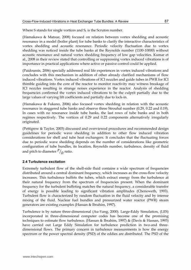
Figure 10 shows the consistency of turbulence intensity contours obtained through standard wall function approach and non-equilibrium wall function approach whereas near-wall treatment model and near -wall turbulence model predicts much higher results (Wang, et al., 2006).
(Non-dimensional frequency)
Dim
ensi
on
less
au
toco
rrel
atio
n s
pec
tru
m
www.intechopen.com
Cross-Flow-Induced-Vibrations in Heat Exchanger Tube Bundles: A Review 91
Fig. 10. Turbulence intensity contours (Barrington, 1973)
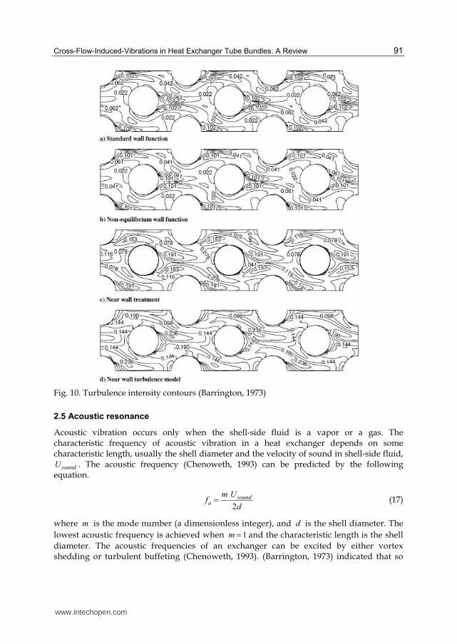
2.5 Acoustic resonance
Acoustic vibration occurs only when the shell-side fluid is a vapor or a gas. The characteristic frequency of acoustic vibration in a heat exchanger depends on some characteristic length, usually the shell diameter and the velocity of sound in shell-side fluid,
soundU . The acoustic frequency (Chenoweth, 1993) can be predicted by the following equation.
2
sounda
m Uf
d (17)
where m is the mode number (a dimensionless integer), and d is the shell diameter. The
lowest acoustic frequency is achieved when 1m and the characteristic length is the shell
diameter. The acoustic frequencies of an exchanger can be excited by either vortex shedding or turbulent buffeting (Chenoweth, 1993). (Barrington, 1973) indicated that so
www.intechopen.com

Nuclear Power Plants 92
long as the exciting frequencies are within 20% of an acoustic frequency, a loud sound may be produced. Acoustic vibration becomes destructive when it is in resonance with some component of exchanger. The acoustic frequencies of shell can be changed by inserting a detuning plate parallel to the direction of cross-flow to alter the characteristic length (Chenoweth, 1993). There are a number of published acoustic vibration criteria to predict strong acoustic vibration within a tube bank, including (Eisinger et al., 1994), (Groth & Arnold, 1956), (Chen, 1968), (Fitzpatrick, 1986), (Ziada et al.,) and Blevins (Blevins, 1990 ).
(Hanson & Ziada, 2011) have investigated the effects of acoustic resonance on the dynamic lift force acting on the central tube. Two effects of resonant sound field includes generation of “sound induced” dynamic lift because of resonant acoustic pressure distribution on the tube surface and synchronization of vorticity shedding. Sound enhancements coefficients and sound induced lift force development is carried through numerical solution. (Hanson et al., 2009) investigated aeroacoustic response of two side-by-side cylinders against cross flow. It is concluded that acoustic resonance synchronizes vortex shedding and eliminates bistable flow phenomenon. Vortex shedding is noticed a particular strouhal number which excites acoustic resonance. Figure 11 and figure 12 gives the pressure spectra for two side-by-side cylinders and aeroacoustic response of two side-by-side cylinders.
(Eisinger & Sullivan , 2007) considers strong acoustic resonance with acoustic pressure reading 165 dB for package boiler at near full load, suppression of resonance (lower frequency) through baffle covering with downstream section and the development of another resonance (higher frequency) in the unbaffled upstream section.
(Feenstra et al., 2006) carried out experimental investigation of the effects of width of test section for measuring the acoustic resonance with a small pitch rates staggered tubes. The conclusion was that the maximum acoustic pressure versus input energy parameter of Blevins and Bressler is not a reliable preditor and it over predicts.
Fig. 11. Pressure spectra for the two side-by-side cylinders for T/D=1.25 (Hanson, et al., 2011)
www.intechopen.com

Cross-Flow-Induced-Vibrations in Heat Exchanger Tube Bundles: A Review 93
Fig. 12. Aeroacoustic response of the two side-by-side cylinders with T/D =1.25 and D =21.8 mm (Hanson, et al., 2011) (Eisinger & Sullivan, 2005) test results concluded that wide test sects gives the maximum acoustic pressure (lower acoustic mode) at P=53.4 MPa which is 4.27 times greater than predicted by Blevins and Bressler.
3. Natural frequencies of tube vibration
In flow-induced vibration design of heat exchanger tube bundles, resonant conditions must be suppressed by ensuring separation of natural frequencies of the tubes and exciting frequencies (Shin & Wambsganss,1975). A number of techniques are available for computing natural frequencies of straight, curved, single and multiple span tubes. These tubes may be subjected to varying end conditions. Loose baffles act like "kinfe-edged rings” supports (Timoshenko, 1955) . Tubes are rigidly fastened to the tube sheet and supported at intermediate points along their lengths by baffles or support plates. Some tubes in the centre may be supported by every baffle, whereas tubes that pass thorough baffle window may be supported by every second and third baffle. Table 5 (MacDuff & Feglar, 1957, Kissel, 1977) gives some of the formulas/techniques for estimating the natural frequencies of straight-and curved-or U-tubes.
3.1 Variables affecting tube natural frequencies
The tube natural frequencies are affected by tube-to-baffle hole clearance, axial stress, fins, span length, span shape (straight, U-tube), support type, temperature and tube vibration (Chenoweth, 1976, Elliot & Park, 1973, Pettigrew et al., 1986, Simpson et al., 1974, Tanaka & Takahara, 1981, TEMA Standards, 8th edition). At about one tenth of TEMA allowable clearance, the frequency is about 7% higher than that predicted for simple supports. For most exchangers, tube-to-hole clearance is not a significant parameter for controlling natural frequencies, but it may be important in damping and tube wear (Chenoweth, 1993). Due to manufacturing procedures, the tubes may be under a tension or compression axial loading. (Kissel, 1972) found a variation in natural frequency due to axial loading in a typical
www.intechopen.com

Nuclear Power Plants 94
exchanger as much as ± 40%. The natural frequency varies as reciprocal of the span length squared (unsupported span). For finned tubes, effective diameter for the outside diameter should be used to find the area moment of inertia for natural frequency calculation (Chenoweth, 1993). Currently, software by TEMA (FIV) (TEMA Standards, 8th edition) is capable of predicting the natural frequencies.
Formula/ Procedure Conditions
1/2
2
1
2
nn
EIf
ml
(Jones, 1970)
Straight beams /single span
n is the mode number and n is a frequency
factor which depends upon the end conditions
1/21 1
2n n
EIf
R m (Archer, 1960)
Curved beams/ single span
n is a frequency factor
R is the radius of curvature and is the subtended angle
0.5
259.55 u
n
e
C EIf
ML
(TEMA, 6th Edition, 1978)
U-tube curved
uC is the first mode U-tube constant
Experimental/ computer program
2
22
nn
L EIgf
WL
(Lowery & Moretti, 1975)
Straight/multiple, free-free spans (1-5 span
tests); idealized support conditions, 2( )nL is
eigen value
FEM in-plane and out of plane Experimental/ analytical (Elliott & Pick, 1973)
Straight/curved
Beams immersed in liquids, air, kerosene, and oil (Jones, 1970)
Straight/simply supported/clamped
Out of plane:
2
2
2
( 1)3.13
1
nn nR
C n nf
A kn
(Ojalvo & Newman, 1964)
Clamped ring segments
n is mode number; k is bending stiffness
is specific weight; C is the torsional stiffness.
A is cross-sectional area
Graphical in-plane and out of plane (Chen & Wambsganss, 1974)
Straight/curved, single span /multiple span
www.intechopen.com
Cross-Flow-Induced-Vibrations in Heat Exchanger Tube Bundles: A Review 95
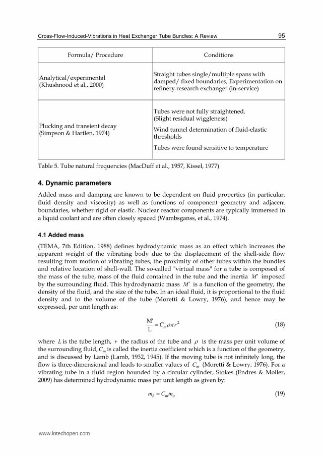
Formula/ Procedure Conditions
Analytical/experimental (Khushnood et al., 2000)
Straight tubes single/multiple spans with damped/ fixed boundaries, Experimentation on refinery research exchanger (in-service)
Plucking and transient decay (Simpson & Hartlen, 1974)
Tubes were not fully straightened. (Slight residual wiggleness)
Wind tunnel determination of fluid-elastic thresholds
Tubes were found sensitive to temperature
Table 5. Tube natural frequencies (MacDuff et al., 1957, Kissel, 1977)
4. Dynamic parameters
Added mass and damping are known to be dependent on fluid properties (in particular,
fluid density and viscosity) as well as functions of component geometry and adjacent
boundaries, whether rigid or elastic. Nuclear reactor components are typically immersed in
a liquid coolant and are often closely spaced (Wambsganss, et al., 1974).
4.1 Added mass
(TEMA, 7th Edition, 1988) defines hydrodynamic mass as an effect which increases the apparent weight of the vibrating body due to the displacement of the shell-side flow resulting from motion of vibrating tubes, the proximity of other tubes within the bundles and relative location of shell-wall. The so-called "virtual mass" for a tube is composed of
the mass of the tube, mass of the fluid contained in the tube and the inertia M imposed
by the surrounding fluid. This hydrodynamic mass M is a function of the geometry, the density of the fluid, and the size of the tube. In an ideal fluid, it is proportional to the fluid density and to the volume of the tube (Moretti & Lowry, 1976), and hence may be expressed, per unit length as:
2M'
LmC r (18)
where L is the tube length, r the radius of the tube and is the mass per unit volume of
the surrounding fluid, mC is called the inertia coefficient which is a function of the geometry,
and is discussed by Lamb (Lamb, 1932, 1945). If the moving tube is not infinitely long, the
flow is three-dimensional and leads to smaller values of mC (Moretti & Lowry, 1976). For a
vibrating tube in a fluid region bounded by a circular cylinder, Stokes (Endres & Moller,
2009) has determined hydrodynamic mass per unit length as given by:
h m am C m (19)
www.intechopen.com

Nuclear Power Plants 96
where 2 2
2 2m
R rC
R r
, R is the outer radius of annulus and, 2am r , where is fluid
density, and r is the tube radius.
(Wambsganss, et al., 1974) have published a study on the effect of viscosity on mC .
Hydrodynamic mass M for a tube submerged in water was determined by measuring its
natural frequency, af , in air and, wf , in water. Neglecting the density of air compared to
water, the following equation may be obtained from beam equation (Moretti & Lowry, 1976).
2
1a
w
fM
L f
(20)
where is the tube mass per unit length. The inertia coefficient, mC , can be obtained from
Equation 18. Figure 13 gives the results showing the variation of mC with pitch-to-diameter
ratios (Wambsganss, et al., 1974).
Fig. 13. Experimental mC -values in tube bundles (Wambsganss et al., 1974, Moretti et al., 1976).
4.2 Damping
System damping has a strong influence on the amplitude of vibration. Damping depends
upon the mechanical properties of the tube material, the geometry of intermediate supports
and the physical properties of the shell-side fluid. Tight tube-to-baffle clearances and thick
baffles increase damping, as does very viscous shell-side fluid (Chenoweth, 1993). (Coit et
al., 1974) measured log decrements for copper-nickel finned tubes of 0.032 in still air. The
range of most of the values probably lies between 0.01 and 0.17 for tubes in heat exchangers
(Chenoweth, 1993). From (Wambsganss, et al., 1974), damping can be readily obtained from
the transfer function or frequency response curve as
P/D ratio
Cm
www.intechopen.com

Cross-Flow-Induced-Vibrations in Heat Exchanger Tube Bundles: A Review 97
2
1
2 1
n
n
f
fN (21)
with (1) (2)n N Nf f f ,
where nf is the resonant frequency and (1) (2) and N Nf f are the frequencies at which the
response is a factor 1thN
of resonant response.
(Lowery & Moretti, 1975), have concluded that damping is almost entirely a function of
the supports. More complex support conditions (non-ideal end supports or intermediate
supports with a slight amount of clearance) lead to values around 0.04. From analytical
point of view, (Jones, 1970) has remarked that in most cases, the addition of damping to
the beam equation re-couples its modes. Only a beam, which has, as its damping function,
a restricted class of functions can be uncoupled. (Chen et al., 1994) have found the fluid
damping coefficients from measured motion-dependent fluid forces. (Pettigrew et al.,
1986, 1991) outlines the energy dissipation mechanisms that contribute to tube damping
as given in Table 6:
Type of damping Sources
Structural Internal to tube material
Viscous Between fluid forces and forces transferred to fluid
Flow-dependent Varies with flow regime.
Squeeze film Between tube and fluid as tube approaches support
Friction Coulomb damping at support
Tube support Internal to support material
Two-phase Due to liquid gas mixture
Thermal damping Due to thermal load
Table 6. Energy dissipation mechanisms (Pettigrew et al., 1986, 1991)
4.3 Parameters influencing damping
(Pettigrew et al., 1986) further outlines the parameters that influence damping as given
below:
The Type of tube motion. There are two principal types of tube motion at the supports, rocking
motion and lateral motion. Damping due to rocking is likely to be less. Rocking motion is
pre-dominant in lower modes. Dynamic interaction between tube and supports may be
categorized in three main types, namely: sliding, impacting, and scuffing, which is
impacting at an angle followed by sliding:
Effect of number of supports. The trend available in damping data referenced in (Pettigrew et al., 1986), when normalized give
www.intechopen.com

Nuclear Power Plants 98
/ ( 1)n N N
(22)
where n is the normalized damping ratio, N is the number of spans, and is the
damping ratio.
Effect of tube Frequency. Frequency does not appear to be significant parameter (Pettigrew et al., 1986).
Effect of vibration amplitude. There is no conclusive trend of damping as a function of amplitude. Very often, amplitude is not given is damping measurements (Pettigrew et al., 1986).
Effect of diameter or mass. Large and massive tubes should experience large friction forces and
the energy dissipated should be large. However, the potential energy in the tube would also
be proportionally large in more massive tubes. Thus, the damping ratio, which is related to
the ratio of energy dissipated per cycle to the potential energy in the tube should be
independent of tube size or mass (Pettigrew et al., 1986).
Effect of side loads. In real exchangers, side loads are possible due to misalignment of tube-
supports or due to fluid drag forces. Side loads may increase or reduce damping. Small side
loads may prevent impacting, and thus reduce damping, whereas large side loads may
increase damping by increasing friction (Pettigrew et al., 1986).
Effect of higher modes. Damping appear to decrease with mode order, for mode order higher than the number of spans, since these higher modes involve relatively less interaction between tube and tube-support (Pettigrew et al., 1986).
Effect of tube support thickness. Referenced data in (Pettigrew et al., 1986) clearly indicates that
support thickness is a dominant parameter. Damping is roughly proportional to support
thickness. (Pettigrew et al., 1986) corrected the damping data line for support width less
than 12.7mm such that
12.7
nc nL
(23)
where L is support thickness in mm and nc is the corrected normalized damping ratio.
Effect of clearance. For the normal range of tube-to-support diametral clearances (0.40mm-0.80mm), there is no conclusive trend in the damping data reviewed (Pettigrew et al., 1986).
Design Recommendations (Pettigrew et al., 1986, 1991, Taylor et al., 1998)
Friction damping ratio in a multi-span tube (percentage)
(For liquid)
1/21
0.5Fm
N L
N l (24)
(For gas)
1/21
5.0 Fm
N L
N l (25)
www.intechopen.com

Cross-Flow-Induced-Vibrations in Heat Exchanger Tube Bundles: A Review 99
where N is the number of tube spans, L is the support thickness, ml is the characteristic
span length usually taken as average of three longest spans.
Viscous damping ratio
Rogers simplified version of Chens' cylinder viscous damping ratio (percentage) of a tube in liquid.
1/2 32
2 2 2
1 ( / )100 2
8 (1 ( / ) )
eF
e
D DD
m fD D D
(26)
where is the fluid density, m is the mass per unit length of tube (interior fluid and
hydrodynamic mass), eD is the equivalent diameter to model confinement due to
surrounding tubes, D is the tube diameter, f is the frequency of tube vibration and is
the fluid kinematic viscosity. The term 2
2
fDS
is the Stoke number.
Squeeze film damping ratio
(For multi-span tube)
1/221 1460
m
N D L
N f m l
(27)
Support damping
(Pettigrew, et al., 1991) has developed a semi-empirical expression to formulate support damping, using Mulcahys' theory (Mulcahy, 1980).
0.621 2200s
m
N D L
N f m l
(28)
(TEMA, 6th Edition, 1978, TEMA, 7th Edition, 1988)
According to TEMA standards, is equal to greater of 1 , and 2
(For shell-side liquids)
1
3.41 o
o n
d
W f (29)
1/2
2
0.012 o o
o n
d v
W f
(30)
where v is the shell fluid velocity, od is the outside tube diameter, o is the density of shell-
side fluid, nf is the fundamental frequency of tube span, and oW is the effective tube
weight.
(For shell-side vapors)
www.intechopen.com

Nuclear Power Plants 100
1/21
0.314 btN
N l (31)
where N is the number of spans, bt is the baffle or support plate thickness, and l is the tube
unsupported span. A review of two-phase flow damping is presented by (Khushnood et al., 2003).
5. Damage numbers for collision and baffle damage (Chenoweth, 1976, Shin et al., 1975, Brothman et al., 1974)
Two types of vibration damage are prevalent in cross-flow regions of steam generators (Shin
& Wambsganss, 1975).
Tube-to-baffle impact.
Tube-to-tube collision.
(Thorngren, 1970) deduced "damage numbers" for the two types of damage, based on the
assumption that tube is supported by baffles and deflected by a uniformly distributed lift
force. These damage numbers are given by following equations:
(Baffle damage number) 2 2
1BD
m c m t
d V lN
S g A B
(32)
(Collision damage number) 2 4
4 2 21
0.625
( )T
CD
c m i
d V lN
g A d d C E
(33)
where
1BDN for safe design. 1CDN for safe design.
TC = Maximum gap between tubes. d = Tube outer diameter.
id = Tube inner diameter. 1 = Tube-to-baffle-hole clearance factor.
E = Modulus of elasticity. cg = Gravitational constant.
tB = Baffle thickness. = Mass density of shell side fluid.
l = Length of tube between supports. V = Free stream velocity.
mA = Tube cross-sectional area 2 2( )4
id d and
mS = Maximum allowable fatigue stress [ASME Pressure Vessel code Sec. III].
Collision damage is usually predicted together with baffle damage, whereas the latter can be
predicted without collision damage being indicated, i.e., baffle damage is important factor
when appraising design (Erskine et al., 1973). (Burgreen et al., 1958) were the first to conduct
an experiment to investigate vibration of tube for fluid flowing parallel to tube axis. (Quinn,
1962) and (Paidoussis, 1965) have developed analytical and empirical expressions
respectively for peak amplitude. Paidoussis give the following expression:
www.intechopen.com

Cross-Flow-Induced-Vibrations in Heat Exchanger Tube Bundles: A Review 101
2/3 40.41.6 1.8 0.25
41 2
(5 10 )
4
pe hKU R d
d d II U
(34)
where
pK = Flow condition constant
= Maximum vibration amplitude at mid-span
d = Outer diameter of tube
1 = First mode beam eigen value of the tube
U = Dimensionless flow velocity
d
= Tube length
hd = Hydraulic diameter
eR = Reynolds number
I = Moment of inertia and = Added mass fraction
Later on a number of expressions for peak and RMS amplitudes have been developed (Shin et al., 1975, Blevins, 1977).
6. Wear work-rates
In fretting wear, work-rate is defined as the rate of energy dissipation when a tube is in contact with its support. Energy is being dissipated through friction as the tube moves around in contact with its supports. A force (the contact force between tube and support) multiplied by a displacement (as the tube slides) results in work or dissipated energy required to move the tube (Taylor et al., 1998, Au-Yang, 1998). Normal work-rate nW for different tube and tube support plate material combinations and different geometries (Au-Yang, 1998) is defined.
0
1T
n nW F dST
(35)
where T is the total time, nF is the normal contact force, and S is the sliding distance.
(Au-Yang, 1998) has assessed the cumulative tube wall wear after 5, 10, and 15, effective full power years of operation of a typical commercial nuclear steam generator, using different wear models.
The EPRI data reproduced from (Hofmann & Schettlet, 1989) in Figure 14 shows the wear
volume against normal work-rate for the combination of Inconel 600 tube (discrepancy as
plot shows J 600 whereas text indicates Inconel 600) and carbon tube support plate, a
condition that applies to many commercial nuclear steam generators (Hofmann & Schettlet,
1989). Figure 15 shows the tube wall thickness loss against volumetric wear for different
support conditions (Hofmann & Schettlet, 1989).
www.intechopen.com

Nuclear Power Plants 102
0.1
Volum e w ear ra te at the tube
(steady sta te data)
"w ork ra te"=590
volum e loss=0.6
"w ork rates"=440
volum e loss=0.46
Pur
e os
cilla
ting
slid
ing
J 600 (tube) against
405 SS (drilled ho le)
carbon stee l(drilled ho le)
"w ork ra te"=800
volum e loss+0.097
Impa
ct +
slid
ing
Pure im
pacting
N m m /s
w ork rate
0 100 200
0.2
0.3
m m /d3
J 600 (tube) against
0
Pure
im
pacting
Pure oscilla ting slid ing
Im pact + slid ing
Fig. 14. Volumetric wear rate versus normal work-rate for different material combinations (Hofmann & Schettlet, 1989).
0 .5
0 .4
0 .3
0 .2
0 .1
0
5 10 1 5
bo re ho le
A V B
T yp e o f m o tio n :p u re im pa c tin gM a te ria ls : th e sa m e fo r tub e an d sup po rt
tu b e w e a r vo lu m e [m m ]3
tube
wa
ll th
ickne
ss r
ed
uctio
n[m
m]
e g g cra te
Fig. 15. Tube wall thickness loss versus volumetric wear for different support conditions, from Hofmann and Schettler (Hofmann & Schettlet, 1989).
www.intechopen.com

Cross-Flow-Induced-Vibrations in Heat Exchanger Tube Bundles: A Review 103
(Payen et al., 1995) have carried predictive analysis of loosely supported tubes vibration
induced by cross-flow turbulence for non-linear computations of tube dynamics. They have
analyzed the gap effect and have concluded that wear work-rate decreases when the gap
value increase at low velocities. (Peterka, 1995) has carried out numerical simulation of the
tubes impact motion with generally assumed oblique impacts. (Charpentier and Payen,
2000) have carried out prediction of wear work-rate and thickness loss in tube bundles
under cross-flow by a probabilistic approach. They have used Archard's Law and wear
correlation depending on the contact geometry, and have concluded that most sensitive
parameters that affect the wear work-rate are the coefficient of friction, the radial gap and
the spectral level of turbulent forces.
(Paidoussis & Li, 1992) and (Chen et al., 1995) have studied the chaotic dynamics of heat
exchanger tubes impacting on the generally loose baffle plates, using an analytical model
that involves delay differential equations. They have developed a Lyapunov exponent
technique for delay differential equations and have shown that chaotic motions do occur.
They have performed analysis by finding periodic solutions and determining their stability
and bifurcations with the Poincare map technique. Hopf bifurcation is defined as the loss of
stable equilibrium and onset of amplified oscillation (Paidoussis & Li, 1992).
2.0 3.0 4.0 5.00.00
0.04
0.08
U
D
H
Fluid Velocity
Dis
pla
ce
me
nt
U
CHU
Fig. 16. The bifurcation diagram (Paidoussis & Li, 1992, Chen et al., 1995)
A typical bifurcation diagram for the symmetric cubical model with / 1.5P D , is given in
Figure 16 showing dimensionless mid-point displacement amplitude in terms of
dimensionless fluid velocity. Where HU denotes critical U for Hopf bifurcation, DU , is the
first post Hopf bifurcation, and CHU denotes the onset of chaos. Total wear work rates
against pitch velocity and mass flux have been given by (Taylor et al., 1995) and
(Khushnood et al., 2003).
www.intechopen.com
Nuclear Power Plants 104
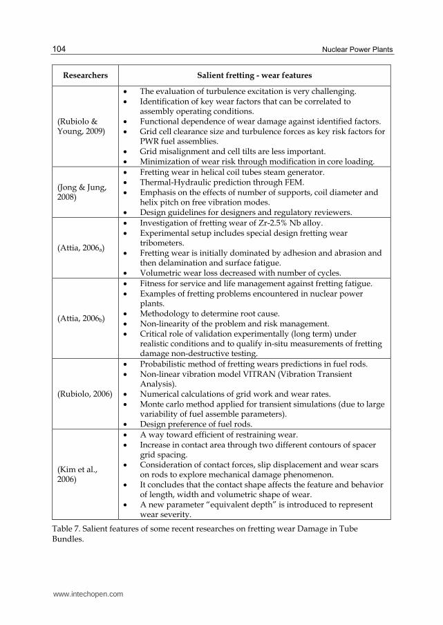
Researchers Salient fretting - wear features
(Rubiolo & Young, 2009)
The evaluation of turbulence excitation is very challenging. Identification of key wear factors that can be correlated to assembly operating conditions. Functional dependence of wear damage against identified factors. Grid cell clearance size and turbulence forces as key risk factors for PWR fuel assemblies. Grid misalignment and cell tilts are less important. Minimization of wear risk through modification in core loading.
(Jong & Jung, 2008)
Fretting wear in helical coil tubes steam generator. Thermal-Hydraulic prediction through FEM. Emphasis on the effects of number of supports, coil diameter and helix pitch on free vibration modes. Design guidelines for designers and regulatory reviewers.
(Attia, 2006a)
Investigation of fretting wear of Zr-2.5% Nb alloy. Experimental setup includes special design fretting wear tribometers. Fretting wear is initially dominated by adhesion and abrasion and then delamination and surface fatigue. Volumetric wear loss decreased with number of cycles.
(Attia, 2006b)
Fitness for service and life management against fretting fatigue. Examples of fretting problems encountered in nuclear power plants. Methodology to determine root cause. Non-linearity of the problem and risk management. Critical role of validation experimentally (long term) under realistic conditions and to qualify in-situ measurements of fretting damage non-destructive testing.
(Rubiolo, 2006)
Probabilistic method of fretting wears predictions in fuel rods. Non-linear vibration model VITRAN (Vibration Transient Analysis). Numerical calculations of grid work and wear rates. Monte carlo method applied for transient simulations (due to large variability of fuel assemble parameters). Design preference of fuel rods.
(Kim et al., 2006)
A way toward efficient of restraining wear. Increase in contact area through two different contours of spacer grid spacing. Consideration of contact forces, slip displacement and wear scars on rods to explore mechanical damage phenomenon. It concludes that the contact shape affects the feature and behavior of length, width and volumetric shape of wear. A new parameter “equivalent depth” is introduced to represent wear severity.
Table 7. Salient features of some recent researches on fretting wear Damage in Tube Bundles.
www.intechopen.com

Cross-Flow-Induced-Vibrations in Heat Exchanger Tube Bundles: A Review 105
A generalized procedure to analyze fretting - wear process and its self - induced changes in properties of the system and flow chart for fretting fatigue damage prediction with the aid of the principles of fracture mechanics is presented in figure 17 & 18 respectively.
Fig. 17. System approach to the fretting wear process and its self-induced changes in the system properties (Attia, 2006a).
Fig. 18. Flow chart for the prediction of fretting fatigue damage, using fracture mechanics principles (Attia, 2006a).
www.intechopen.com

Nuclear Power Plants 106
7. Tube bundle vibrations in two-phase cross-flow
7.1 Modeling two-phase flow
Most of the early experimental research in this field relied on sectional models of tube arrays
subjected to single-phase fluids such as air or water, using relatively inexpensive flow loops
and wind tunnels. The cheapest and simplest approach to model two-phase flow is by
mixing air and water at atmospheric pressure. However, air-water flows have a much
different density ratio between phases than steam-water flow and this will affect the
difference in the flow velocity between the phases. The liquid surface tension, which
controls the bubble size, is also not accurately modeled in air-water mixtures. Table 8 gives
the comparison of liquid and gas phase of refrigerants R-11, R-22 and air-water mixtures at
representative laboratory conditions with actual steam-water mixture properties at typical
power plant conditions (Feentra et al., 2000). This comparison reveals that the refrigerants
approximate the liquid surface tension and liquid dynamic viscosity of steam-water
mixtures more accurately than air-water mixtures.
Property R-11 Air-water R-22 Steam-water
Temperature (0C) 40 22 23.3 260
Pressure (kPa) 175 101 1000 4690
Liquid Density (kg/m3) 1440 998 1197 784
Gas Density (kg/m3) 9.7 1.18 42.3 23.7
Liquid kinematic viscosity (m2/sec) 0.25 1.0 0.14 0.13
Gas kinematic Viscosity (m2/sec) 1.2 1.47 0.30 0.75
Liquid Surface Tension (N/m) 0.016 0.073 0.0074 0.0238
Density Ratio 148 845 28.3 33
Viscosity Ratio 0.20 0.70 0.47 0.17
Table 8. Comparison of properties of air-water, R-22, and R-11 with steam-water at plant conditions (Feentra et al., 2000)
Typical nuclear steam generators such as those used in the CANDU design utilize more than
3000 tubes, 13mm in diameter, formed into an inverted U-shape. In the outer U-bend region,
these tubes are subject to two-phase cross-flow of steam-water which is estimated to be of 20%
quality. It is highly impractical and costly to perform flow- induced vibration experiments on a
full-scale prototype of such a device so that small-scale sectional modeling is most often
adopted. R-11 simulates the density ratio, viscosity ratio and surface tension of actual steam-
water mixtures better than air-water mixtures and it also allows for localized phase change
which air-water mixture does not permit. While more costly and difficult to use than air-water
mixture, R-11 is a much cheaper fluid to model than steam-water because it requires 8% of the
energy compared with water to evaporate the liquid and operating pressure is much lower,
thereby reducing the size and cost of the flow loop (Feentra et al., 2000).
7.2 Representative published tests on two-phase flow across tube arrays
Table 6, an extension of period beyond 1993 (Pettigrew et al., 1973) presents a summary of salient features of the experimental tests performed on the three possible tube arrangements (triangular, normal square, and rotated square).
www.intechopen.com

Cro
ss-F
low
-Ind
uce
d-V
ibra
tion
s in
He
at E
xch
an
ge
r Tu
be
Bu
nd
les: A
Re
vie
w
107
Researchers Fluid Tube Array Void Fraction Tube
Length (mm)
Natural Frequency
(Hz)
Damping Ratio (%)
(Pettigrew et al., 1973) Air-Water Triangular/ Parallel. Square/Rotated Square
10-20% (quality)
50.8 17- 30 2.5-2.7
(Heilker & Vincent, 1981) Air-Water Triangular/ Rotated Square 0.5 – 0.87 910 56-62 0.8-4 (Hara et al., 1981) Air-Water Single Tube 0.02 – 0.61 60 Rigid –(Remy, 1982) Air-Water Square 0.65 – 0.85 1000 56.6 0.6-1.75(Nakamura et al., 1982) Air-Water Square/ Rotated Square 0.2 – 0.94 190 142 1.3-1.7 (Pettigrew et al., 1985) Air-Water Triangular/ Square 0.05-0.98 600 26-32 0.9-8.0 (Axisa et al., 1984) Steam-Water Square 0.52-0.98 1190 74 0.2-3.0 (Nakamura et al., 1986) Steam-Water Square 0.75-0.95 174 15.2 –16 4.0-8.0 (Hara, 1987) Air-Water Single/Row 0.01-0.5 58 6.0-8.4 2.9-15.6 (Goyder, 1988) Air-Water Triangular 0.5-0.8 360 175 -- (Gay et al., 1988) Freon Triangular 0.58-0.84 1000 39.8 0.89-1.7 (Nakamura & Fujita, 1988) Air-Water Square 0.02-0.95 600 52 2.1 (Funakawa et al., 1989) Air-Water Square/ Triangular 0.0-0.6 100 12.8 3.3(Nakamura et al., 1990) Steam-water Square 0.33-0.91 174 94-137 --
(Axisa et al., 1990) Steam-water Square/ Triangular Parallel/ Triangular
0.52-0.99 1190 72 0.2-4
(Papp & Chen, 1994) -- Normal triangular / Normal Square/ Parallel Triangular
25-98% -- -- --
(Pettigrew, Taylor, Jong & Currie, 1995)
Freon Rotated triangular 40-90% 10-90% 609 28-150 0.15
(Noghrehkar et al., 1995) Air-Water Square fifth & sixth row 0-90% 200 15-25 0.3-3.9
(Taylor et al., 1995) Air-Water U-bend tube bundle with 1800 U-tubes parallel triangular configuration
0-90% U-Tube
radii 0.6-0.7m
23-114 1.5-2
Marn & Catton (Marn & Catton, 1996)
Air-Water Normal triangular, Parallel triangular, & rotated square
5-99% -- -- 0.7-21
(Taylor & Pettigrew, 2000) Freon Rotated triangular & Rotated Square 50-98% 609 -- 0.2-5
(Pettigrew et al., 2000) Air-Water Normal 300 & rotated 600 triangular, Normal 900 & rotated 450 square
0-100% 600 30-160 1-5
ww
w.intechopen.com

N
ucle
ar P
ow
er P
lan
ts
108
* Resu
lts 1973-1993 (Pettig
rew et al., 1973)
Tab
le 9. Rep
resentativ
e Pu
blish
ed T
ests on
Tw
o- P
hase F
low
Researchers Fluid Tube Array Void Fraction Tube
Length (mm)
Natural Frequency
(Hz)
Damping Ratio (%)
51 891 %07-0 erauqS retaW-riA )0002 ,.la te adanI(
-2.5 - +1.6% Eq.
added damping coefficient
(Nakamera et al., 2000) Freon 46x5 U-bend tubes, specification of actual westinghouse type-51 series steam generator.
(Not considered)based on
Connors single-phase relation.
-- 16-26 Damping ratio <1%
(Feentra et al., 2000) R-11 Parallel/Triangular 0-0.99 -- 0-100 1.1-2.9
(Pettigrew & Taylor, 2003) Steam-water
general overview
General overview General
overview General
overview General
overview General
overview
(Chung & Chu, 2005) Air-water Normal square/rotated square Void fraction
10-95% --
18.65-20.7 Hz
0.01-0.05
(Parsad et al., 2007) Steam-water
general overview
General overview General
overview General
overview General
overview General
overview
(Pascal-Ribot & Blanchet, 2007)
%08-01 rednilyc digiR retaw-riADia=100
mm 0-25 Hz -
(Kakac & Bon, 2008) Steam-water
general overview
General overview General
overview General
overviewGeneral
overview General
overview
(Mitra et al., 2009) Air-water / Steam-water
Normal square tube array suspended from piano wires
Void fraction 0-45%
Dia=190mm
7.84-13.9 Hz
3.3-5.2
(Sim & Park, 2010) -- Cantilevered flexible cylinder 3-38% Dia=123
mm 12Hz
0.1128-0.1154
(Chu et al., 2011) Air-water U-tube rotated square 70-95% Dia=19.0
5mm4-12 Hz 0.0038
ww
w.intechopen.com

Cross-Flow-Induced-Vibrations in Heat Exchanger Tube Bundles: A Review 109
7.3 Thermal hydraulic models
Considering two-phase flow, homogenous flow assumes that the gas and liquid phases are flowing at the same velocity, while other models for two-phase flow, such as drift-flux assume a separated flow model with the phases allowed to flow at different velocities. Generally the vapor flow is faster in upward flow because of the density difference.
7.3.1 The homogenous equilibrium model
Homogenous Equilibrium Model (HEM) treats the two-phase flow as finely mixed and homogeneous in density and temperature with no difference in velocity between the gas and liquid phases.
A general expression for void fraction , is given in (Feentra et al., 2000).
11
1 ( 1)G
L
Sx
(36)
where G and L are the gas and liquid densities respectively and S is the velocity ratio of
the gas and liquid phase (i.e. /G LS U U ). The quality of the flow x is calculated from
energy balance, which requires measurement of the mass flow rate, the temperature of the
liquid entering the heater, the heater power, and the fluid temperature in the test section.
The HEM void fraction H is the simplest of the two-phase fluid modeling, whereby the
gas and liquid phases are assumed to be well mixed and velocity ratio S in Equation 36 is
assumed to be unity. The average two-phase fluid density is determined by Equation 37.
(1 )G L (37)
The HEM fluid density H is determined using Equation 32 by substituting H in place of
. The HEM pitch flow velocity PV is determined by
/P P HV G
(38)
Where Gp=Pitch mass flux
7.3.2 Homogenous flow (Taylor & Pettigrew, 2000)
This model assumes no relative velocity between the liquid velocity 1U and the gas velocity
gU . Slip S between the two-phases is:
11: ;h gS U U U
g
gg l
j
j j (39)
where hU is the homogeneous velocity, gU is the gas phase velocity, lU is the liquid phase velocity, g is the homogenous void fraction, gj is superficial gas velocity and lj is the superficial liquid velocity.
www.intechopen.com
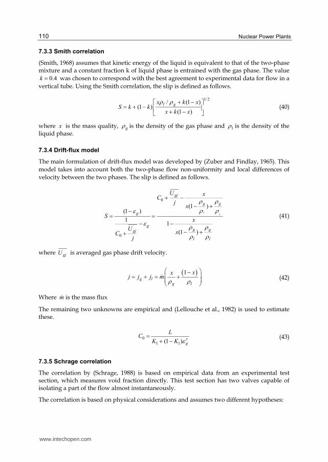
Nuclear Power Plants 110
7.3.3 Smith correlation
(Smith, 1968) assumes that kinetic energy of the liquid is equivalent to that of the two-phase mixture and a constant fraction k of liquid phase is entrained with the gas phase. The value
0.4k was chosen to correspond with the best agreement to experimental data for flow in a
vertical tube. Using the Smith correlation, the slip is defined as follows.
1/2/ (1 )
(1 )(1 )
l gx k xS k k
x k x
(40)
where x is the mass quality, g is the density of the gas phase and 1 is the density of the liquid phase.
7.3.4 Drift-flux model
The main formulation of drift-flux model was developed by (Zuber and Findlay, 1965). This
model takes into account both the two-phase flow non-uniformity and local differences of
velocity between the two phases. The slip is defined as follows.
0
0
(1 )(1 )
11
(1 )
ll
gj
g g
g
gg ggj
l l
U xC
jx
Sx
UxC
j
(41)
where gjU is averaged gas phase drift velocity.
1
g lg l
xxj j j m
(42)
Where m is the mass flux
The remaining two unknowns are empirical and (Lellouche et al., 1982) is used to estimate these.
0
1 1(1 ) rg
LC
K K (43)
7.3.5 Schrage correlation
The correlation by (Schrage, 1988) is based on empirical data from an experimental test section, which measures void fraction directly. This test section has two valves capable of isolating a part of the flow almost instantaneously.
The correlation is based on physical considerations and assumes two different hypotheses:
www.intechopen.com

Cross-Flow-Induced-Vibrations in Heat Exchanger Tube Bundles: A Review 111
The Schrage correlation is as follows:
/g gh = 1+0.123 Fr-0.191lnx (44)
with
Fr = l
mgD (45)
This correlation was established with an air-water mixture, but it remains valid for any
other phase flow.
7.3.6 Feenstra model
In this model (Feentra et al., 2000), predicted velocity ratio of the phases is given by
S = 1+25.7(Ri Cap)0.5 (P/D)-1 (46)
Where Cap is the capillary number and Ri is the Richardson number
7.3.7 Comparison of void fraction models
The HEM greatly over-predicts the actual gamma densitometer void fraction measurement
and the prediction of void fraction model by Feenstra et al., is superior to that of other
models. It also agrees with data in literature for air-water over a wide range of mass flux
and array geometry (Feentra et al., 2000). The main problem with using the HEM is that it
assumes zero velocity ratios between the gas and liquid phases. This assumption is not valid
in the case of vertical upward flow, because of significant buoyancy effects.
7.4 Dynamic parameters
7.4.1 Hydrodynamic mass
Hydrodynamic mass hm is defined as the equivalent external mass of fluid vibrating with
the tube. It is related to the tube natural frequency f in two-phase mixture as discussed in
(Carlucci & Brown, 1997) and is given below:
2[( / ) 1]h t gm m f f (47)
where tm is the mass of tube alone and gf is the natural frequency in air.
Hydrodynamic mass depends on the pitch-to-diameter ratio of the tube, and is given by
(Pettigrew et al., 1989)
22
2
( / ) 1
4 ( / ) 1
e
h
e
D ddm
D d (48)
where is the two-phase mixture density.
www.intechopen.com

Nuclear Power Plants 112
/ (0.96 0.5 / ) /eD d P d P d , for a triangular bundle. (49a)
/ (1.07 0.56 / ) /eD d P d P d , for a square bundle. (49b)
where eD is equivalent diameter to model confinement due to the surrounding tubes as given by (Rogers et al., 1984).
Early air-water studies (Carlucci, 1980) showed that added mass decreases with the void
fraction as shown in Figure 19. It is also less than (1 ), where is the void fraction. This
deviation from expected (1 ) line is caused by the air bubble concentrate at the flow
passage center. Surprisingly added mass has attracted very little attention of researchers which is a potential avenue for future researches.
Fig. 19. Added mass as a function of void fraction (Carlucci, 1980).
7.4.2 Damping in two-phase
Subtracting the structural damping ratio from the total yields the two-phase fluid-damping ratio (Noghrehkar et al., 1995). Total damping includes structural damping, viscous damping and a two-phase component of damping as explained by (Pettigrew et al. 1994). The damping ratio increases as the void fraction increases and peaks at 60% (Carlucci, 1983), then the ratio decrease with (Figure 20). Damping also decreases as the vibration
frequency increases (Pettigrew et al., 1985).
0
0.2
0.4
0.6
0.8
1
1.2
0 10 20 30 40 50 60 70 80 90 100
Ad
de
d m
as
s r
ati
o
Void fraction %
www.intechopen.com

Cross-Flow-Induced-Vibrations in Heat Exchanger Tube Bundles: A Review 113
Fig. 20. Damping ratio as a function of void fraction (Carlucci, 1983).
Damping in two-phase is very complicated. It is highly dependent upon void fraction and flow regime. The results for the two-phase component of damping can be normalized to take into account the effect of confinement due to surrounding tubes by using the
confinement factor C (Pettigrew et al., 2000). This factor is a reasonable formulation of the
confinement due to /P D . As expected, greater confinement due to smaller /P D increase
damping. The confinement factor is given by equation below:
3
2 2
[1 ( / ) ]
[1 ( / ) ]
e
e
D DC
D D (50)
7.5 Flow regimes
Many researchers have attempted the prediction of flow regimes in two-phase vertical flow. As yet, a much smaller group has examined flow regimes in cross-flow over tube bundles. Some of the first experiments were carried out by I.D.R. Grant (Collier, 1979) as it was the only available map at the time. Early studies in two-phase cross-flow used the Grant map to assist in identifying tube bundle flow regimes (Pettigrew et al., 1989) and (Taylor et al., 1989). More recently, Ulbrich & Mewes [180] performed a comprehensive analysis of available flow regime data resulting in a flow regime boundaries that cover a much larger
0
1
2
3
4
5
6
0 20 40 60 80 100
Da
mp
ing
ra
tio
%
Void fraction %
Normal square
Parallel trangular
Normal triangular
www.intechopen.com

Nuclear Power Plants 114
range of flow rates. They found that their new transition lines had an 86% agreement with available data. Their flow map is shown in Figure 21 by (Feenstra et al., 1990) with the flow regime boundary transitions in solid lines and the flow regimes identified with upper-case text. The dotted lines outline a previous flow regime map based on Freon-11 flow in a vertical tube from (Taitel et al., 1980).
Fig. 21. Flow regime map for vertically upward two-phase flow: From (Feenstra et al., 1986,
Taitel et al., 1980). (Pettigrew et al., 1989), (Axisa, 1985), (Pettigrew et al., 1995), (Feenstra et al., 1995).
Almost every study of flow regimes in tube bundles has concluded that three distinct flow
regimes exist. In fact, several studies have shown that these regimes can easily be identified
by measuring the probability density function (PDF) of the gas component of the flow
(Ulbrich & Mewes, 1997), (Noghrehkar et al., 1995) and (Lian et al., 1997).
7.6 Tube to restraint interaction (wear work-rate)
Significant tube-to-restraint interaction can lead to fretting wear. Large amplitude out-of-
plane motion will result in large impact forces and in-plane motion will contribute to
rubbing action. Impact force and tube-to-restraint relative motion can be combined to
determine work-rate. Work-rate is calculated using the magnitude of the impact force and
the effective sliding distance during line contact between the tube and restraint (Chen et al.,
1995). The work-rate is given below in Equations 54 and 55.
www.intechopen.com

Cross-Flow-Induced-Vibrations in Heat Exchanger Tube Bundles: A Review 115
0
1n
i i
s i
W FdST
(51)
1
0 0
1 1
2
n ni i
i i is si i
F FW F S S
T T
(52)
where iF is the instantaneous normal force, iS is the sliding distance during line contact and n is the number of points discretized over the sample duration sT . As the work-rate increases, the effective wear rate increases and the operational life of the U-bend tube decreases. Implementation of the technology is described in detail by (Fisher et al., 1991). Measured values of wear work-rate for pitch velocity and mass flux (Chen et al., 1995) are presented in Figures 22a and 22b respectively. The effect of fluid-elastic forces is very evident in the measured work-rates.
It is interesting to note that at higher pitch velocities and/or mass fluxes, the wear work-rate does not increase. Further study is required to understand why the flow-rates do not affect the work-rates. This may be related to the fact that at high void fractions and high flow rates the random excitation forces are constant with increasing flow rate (Taylor, 1992).
Fig. 22(a). Measured work-rate versus pitch velocity (Chen et al., 1995)
0
5
10
15
20
25
30
35
0 2 4 6 8
To
tal W
ork
ra
te(m
W)
Pitch velocity (m/s)
0% void
25% void
50% void
75% void
90% void
www.intechopen.com
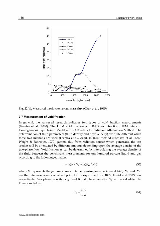
Nuclear Power Plants 116
Fig. 22(b). Measured work-rate versus mass flux (Chen et al., 1995).
7.7 Measurement of void fraction
In general, the surveyed research indicates two types of void fraction measurements
(Feentra et al., 2000). The HEM void fraction and RAD void fraction. HEM refers to
Homogeneous Equilibrium Model and RAD refers to Radiation Attenuation Method. The
determination of fluid parameters (fluid density and flow velocity) are quite different when
these two methods are used (Feentra et al., 2000). In RAD method (Feenstra et al., 2000,
Wright & Bannister, 1970) gamma flux from radiation source which penetrates the test
section will be attenuated by different amounts depending upon the average density of the
two-phase flow. Void fraction can be determined by interpolating the average density of
the fluid between the benchmark measurements for one hundred percent liquid and gas
according to the following equation.
ln( / ) / ln( / )L G LN N N N (53)
where N represents the gamma counts obtained during an experimental trial, LN and GN
are the reference counts obtained prior to the experiment for 100% liquid and 100% gas
respectively. Gas phase velocity, GU , and liquid phase velocity LU can be calculated by
Equations below:
PG
G
xGU (54)
0
5
10
15
20
25
30
35
40
0 500 1000 1500 2000 2500
To
tal w
ork
ra
te(m
W)
mass flux(kg/sqr m-s)
0% void
25% void
50% void
75% void
90% void
www.intechopen.com

Cross-Flow-Induced-Vibrations in Heat Exchanger Tube Bundles: A Review 117
(1 )
(1 )
PL
L
x GU
(55)
where pG is the pitch mass flux.
A logical measure of an equivalent two-phase velocity, eqV is determined from averaging the dynamic head of the gas and liquid phases as given by equation below:
2 2[ (1 ) ] /eq G G L LV U U (56)
8. Conclusions
Loss of Millions of Dollars through Cross-Flow-Induced-Vibrations related problems in
steam generators and heat exchangers excitations has been a cause of major concern in
process, power generation and nuclear industries. Flow-Induced Vibration pose a
potential problem to designers, process engineers and plant operating and maintenance
personnel. Such vibrations lead to motion of tubes in loose supports of baffles of tube
bundles, resulting in mechanical damage, fretting wear, leaking and fatigue etc. Heat
exchanger tubes are the most flexible components of the assembly. The risk of radiation
exposure is always present in case of leakage in steam generator of PWR plants due to
vibration related tube failures.
A number of design consideration have been reviewed in this chapter in order to achieve
design improvements to support large scale heat exchangers with increased shell-side cross-
flow-velocities. The prime consideration is the natural frequency of tubes in a bundle
against cross-flow-induced-vibrations. Various analytical, experimental and computational
techniques for straight & curved tubes have been discussed with reference to single and
multiple spans and varying end and intermediate support conditions. Earlier, Flow-
Induced-Vibration analysis was based upon the concept of two types of damage numbers
(Collision damage and baffle damage). Discussion on these damage numbers and on the
parameters that influence damping has been included.
Next consideration is the generally accepted following four tube bundle vibration excitation
mechanisms (various models have been discussed & reviewed) including steady, unsteady,
analytical, FEM based, CFD based, experimental, empirical correlation based, large eddy
simulation (LES) based, linear and non-linear etc.
Turbulent Buffeting -
It can not be avoided in Heat Exchangers and is caused due to turbulence.
Vorticity Excitation - Vortex shedding or periodic wake Shedding
Fluid-Elastic Instability -
Self excited vibration resulting from interaction of tube motion and flow is the most dangerous excitation mechanism.
Acoustic Resonance -
Caused by some flow excitation having frequency which coincides with natural frequency.
www.intechopen.com

Nuclear Power Plants 118
Dynamic parameters like added mass and damping which are function of geometry, density of fluid and tube size have been targeted by a number of researches in single-phase and two-phase flow. These researches have identified seven separate sources of damping which have been highlighted.
Tube wear due to non-linear tube-to-tube support plate interactions caused by gap clearances between interacting components resulting in thickness loss and normal wear work-rates have been reviewed. Chaotic dynamics of tubes impacting generally on loose baffle plates with consideration of stability and bifurcation have been discussed.
Two-phase Cross-Flow-Induced-Vibrations in tube bundles of process heat exchanger and U-bend region of Nuclear Steam generators can cause serious tube factures by fatigue and fretting wear. Solution to such problems require understanding of vibration excitation and damping mechanism in two-phase flow. This further requires consideration of different flow regimes which characterize two-phase flow. The discussion includes the most important parameter which is void fraction, various thermal-hydraulic models, dynamic parameters, wear work-rates, void fraction measurement and application of TEMA/ASME and other codes have been reviewed. In conclusion the objective of this chapter is to suggest improvements in the design guidelines from the available researches to use the related equipment at optimal performance level.
9. Acknowledgements
We are deeply indebted to University of Engineering & Technology, Taxila – Pakistan, PASTIC, Islamabad – Pakistan and College of EME NUST, Rawalpindi – Pakistan for providing financial, administrative and technical support. We sincerely appreciate the support provided by Mr. Zahid Iqbal, Mr. Riffat Iqbal and Mr. Muhammad Shafique in finalizing the manuscript.
10. References
Antunes, J., Villard, B., Axisa, F., 1985," Cross-flow induced vibration of U-bend tubes of a steam-generator ", Proceedings of SMiRT, F-16/9, pp. 229-239.
Archer, R. R., 1960, "Small vibrations of thin incomplete circular rings", International Journal of Mech. Science, Vol. 1, pp. 45-66.
Attia, M. H. 2006a, “Fretting fatigue and wear damage of structural components in nuclear power stations-Fitness for service and life management perspective,” Tribolgy International, 39, 1294-1304.
Attia, M. H. 2006b, “On the fretting wear mechanism of Zr-alloys,” Tribolgy International, 39, 1320-1326.
Au-Yang, M. K., 1998, “Flow-induced wear in steam generator tubes-prediction versus operational experience”, ASME Journal of Pressure Vessel Technology, Vol. 120, pp. 138-143.
Au-Yang, M. K., 2000, "Joint and cross-acceptances for cross-flow induced Vibration-Part I: Theoretical and Finite Element Formulations", Journal of Pressure Vessel Technology, Vol. 122, pp.349 -354.
Au-Yang, M. K., 2000, "The crossing frequency as a measure of heat exchanger support plate effectiveness", Proceedings of the 7th International Conference on Flow-
www.intechopen.com

Cross-Flow-Induced-Vibrations in Heat Exchanger Tube Bundles: A Review 119
Induced Vibrations, FIV-2000, Lucerne, Switzerland, June 19-22, ISBN 90 5809, 1295, pp. 497-504.
Axisa, F., and Izquierdo, P., 1992, "Experiments on vibro-Impact-Dynamics of loosely supported tubes under harmonic excitation", Proceedings of International Symposium on Flow-Induced Vibration and Noise, Vol. 2, ASME, PVP. 242, eds., Paidoussis, M. J., Chen, S.S., and Steininger, D.A.
Axisa, F., Antunes, J. and Villard, B., 1990, "Random excitation of heat exchanger tubes by cross-flows", Journal of Fluid and Structures, Vol. 4, p. 321.
Axisa, F., Villard, B., Gibert, R. J., Hostroni, G., and Sundheimer, P., 1984, "Vibration of tube bundles subjected to air-water and steam-water cross-flow", ASME Winter Annual Meeting, p. 269.
Balsa, T. F., 1977, "Potential flow interactions in an array of cylinders in cross-flow", Journal of Sound and Vibration, Vol. 50, pp. 285-303.
Barrington, E. A., 1973, "Experience With acoustic Vibrations in tubular exchangers", Chem. Eng. Prog. Vol. 69. No. 7, pp. 62-68.
Blevins, R. D., 1974, "Fluid-elastic whirling of a tube row", ASME Journal of Pressure Vessel Technology, Vol. 96, pp. 263-267.
Blevins, R. D., 1977, "Flow-induced vibration", Van Nostrand Reinhold Company. Blevins, R. D., 1979, "Fluid damping and the whirling instability of tube arrays", In flow-
Induced Vibrations (eds. S. S., Chen and M.D. Bernstein), New York: ASME, pp. 35-39. Blevins, R. D., 1990, "Flow-Induced Vibration", Second Edition, Van Nostrand Reinhold Co.,
New York, N.Y. Botros K. K., and Price G., 2000, "A case study of fluid -elastic instability of a large heat
exchanger in a petrochemical process plant", Proceedings of the 7th International Conference on Flow-Induced Vibrations, FIV-2000, Lucerne, Switzerland, June 19-22, ISBN 90 5809, 1295, pp. 489-496.
Brothman, A., Devore, A., Hollar, G.B., Horowitz, A., and Lee, H.T., 1974, "A tube vibration analysis method", AIChE Symposium Series No. 138, Vol. 70, pp. 190-204.
Burgreen, D., Byrnes, J. J., and Benforado, 1958, "Vibration of rods induced by water in parallel flow", Trans. ASME, Vol. 80, pp. 991-1003.
Carlucci, L. N., 1980, "Damping and hydrodynamic mass of a cylinder in simulated two-phase flow", Journal of Mech. Design, Vol. 102, pp. 597-602.
Carlucci, L. N., and Brown, J.D., 1983, "Experimental studies of damping and hydrodynamic mass of a cylinder in confined two-phase flow", ASME Journal of Vibration, Acoustics, Stress Reliability in Design, Vol. 105, pp.83-89.
Charpentier, J., and Payen, Th., 2000, "Prediction of wear work-rate and thickness loss in tube bundles under cross-flow by a probabilistic approach", Proceedings of the 7th International Conference on Flow-Induced Vibrations, FIV-2000, Lucerne, Switzerland, June 19-22, ISBN 90 5809, 1295, eds., Ziada, S., and Staubli, T, pp.521-528.
Chen, S. S., 1983, "Instability mechanisms and stability criteria of a group of circular cylinders subject to cross-flow", Part-II: Numerical Results and Discussion, Journal of Vibration, Acoustics, Stress and Reliability in Design, Vol. 105, pp. 253-260.
Chen, S. S., 1984, "Guidelines for the instability flow velocity of tube arrays in cross-flow", Journal of Sound and Vibration, Vol. 93, pp. 439-455.
Chen, S. S., 1987, "A general theory for the dynamic instability of tube arrays in cross-flow", Journal of Fluids and Structures, Vol. 1, pp.35-53.
Chen, S. S., 1989, "Some issues concerning fluid-elastic instability of a group of cylinders in cross-flow", ASME Journal of Pressure Vessel Technology, Vol. 111, pp. 507-518.
www.intechopen.com

Nuclear Power Plants 120
Chen, S. S., 1990, "Unsteady fluid forces and fluid-elastic vibration of a group of circular cylinders", Proceedings of ASME, Forum on unsteady flow (ed. Rathe, P.M.) ASME Publication, PVP, Vol. 204, pp. 1-6.
Chen, S. S., Zhu, S., and Cai, Y., 1995, "Experiment of chaotic vibration of loosely supported tube in cross-flow", ASME Journal of Pressure Vessel Technology, Vol. 117, pp. 204-211.
Chen, S.S., 1987, "Flow-induced vibration of circular cylindrical structures", Washington: Hemisphere Publishing.
Chen, S.S., and Wambsganss, M.W., 1974, "Design guide for calculating natural frequencies of straight and curved beams on multiple supports", ANL-CT-74-06, Components Technology Division, Argonne National Laboratory, Argonne, Illinois.
Chen, S.S., Zhu, S., and Jendrzejczyk, J.A., 1994, "Fluid damping and fluid stuffiness of a tube row in cross-flow", ASME Journal of Pressure Vessel Technology, Vol. 116, pp. 370-383.
Chen, Y. N., 1968, "Flow-induced vibration and noise in tube bank of heat exchangers due to von Karaman Streets", ASME Journal of Engineering Industry, Vol. 90, pp. 134-146.
Chenoweth, J. M., Chisholm, D., Cowie, R. C., Harris, D., Illingworth, A., Loncaster, J. F., Morris, M., Murray, I., North, C., Ruiz, C., Saunders, E. A. D., Shipes, K.V., Dennis Usher, and Webb, R. L., 1993, Heat Exchanger Design Handbook HEDH, Hemisphere Publishing Corporation.
Chenoweth, J.M., 1976, "Flow-Induced vibrations in shell-and-tube heat exchangers", Final report: Research on Heat Exchanger Tube Vibration, Contract No. EY-76-C-03-1273, Workshop, June 27-28, Pasadena, California.
Chu, I. C., Chung, H. J., & Lee, S. 2011, “Flow-induced vibration of nuclear steam generator U-tubes in two-phase flow,” Nuclear Engineering and Design, 241, 1508–1515.
Chung, H. J., & Chu, I. C. 2006, “Fluid-Elastic Instability Of Rotated Square Tube Array In An Air-Water Two-Phase Cross-Flow,” Nuclear Engineering And Technology, Vol.38, No.1.
Coit, R. L., Ritland, P. D., Rabas, T. J., and Viscovich, P. W., 1974, "Moisture Separator Reheater: Entering the Second Decade, Two-phase flow in turbines", Short course, Rhode-Saint-Genese, Belguim.
Collier, J., 1979, "Convective boiling and condensation", Oxford Science Publication. Connors, H. J., and Parrondo, J., 1970, "Fluid-elastic vibration of tube arrays excited by cross-
flow", In Flow-Induced Vibration in Heat Exchangers (ed. D. D., Reiff), New York: ASME, pp. 42-56.
Dalton, C., 1980, "Inertia coefficients for riser configurations", In Energy Technology Conference and Exhibition, New Orleans, paper 80-Pet-21, York: ASME.
Dalton, C., and Helfinstein, R. A., 1971, "Potential flow past a group of circular cylinders", ASME Journal of Basic Engineering, Vol. 93, pp. 636-642.
Davis (Jr), F.J., and Hassan, Y. A., 1993, "A two-dimensional finite element method large eddy Simulation for application to turbulent steam generator flow".
Delaigue, D., and Planchard, J., 1986, "Homogenization of potential flow models for the dynamics of cylinder arrays in transient cross-flow", In ASME Symposium on Flow-Induced Vibrations (ed S. S. Chen, J. C. Simonis and Y. S. Shin), PVP-Vol. 104, New York: ASME, pp. 139-145.
Eisinger, F. L., & Sullivan, R. E. 2005, “Acoustic Vibration Behavior of Full Size Steam Generator and Tubular Heat Exchanger In-line Tube Banks,” Proceedings of ASME Pressure Vessels & Piping Division Conference, July 17- 21, Denver USA.
www.intechopen.com
Cross-Flow-Induced-Vibrations in Heat Exchanger Tube Bundles: A Review 121
Eisinger, F. L., & Sullivan, R. E. 2007, “Acoustic resonance in a Package boiler and its solution-A case study,” Journal of Pressure Vessel Technology, Vol. 129.
Eisinger, F. L., Sullivan, R. E., and Francis, J. T., 1994, "A review of acoustic vibration criteria compared to in-service experience with steam generator in-line tube banks", ASME Journal of Pressure Vessel Technology, Vol. 116, pp. 17-23.
Elliott, G.L., and Pick, R.J., 1973, "Calculation of natural frequencies of heat exchanger tubes", Proceedings of International Symposium on Vibration Problems in Industry", Keswick, U.K.
Endres, L. A. M., & Möller, S. V. 2009, “Experimental Study of the Propagation of a Far-Field Disturbance in the Turbulent Flow through Square Array Tube Banks,” Journal of the Braz. Soc. of Mech. Sci. & Eng., Vol. XXXI, No. 3.
Erskine, J.B., and Waddington, W., 1973, "A review of some tube vibration failures in shell and tube heat exchangers and failure prediction methods", Proceedings of International Symposium on Vibration Problems in Industry, Keswick U.K., pp.1-9.
Feenstra, P. A., Judd, R. L., and Weaver, D.S., 1995, "Fluid-elastic instability in a tube array subjected to two-phase R-11 Cross-flow", Journal of Fluids and Structures, Vol. 9, pp. 747-771.
Feenstra, P. A., Weaver, D. S., & Eisinger, F. L. 2006, “A Study Of Acoustic Resonance in Staggered Tube Array,” Journal of Pressure Vessel Technology, Vol.128.
Feenstra, P. A., Weaver, D. S., and Judd, R. L., 1996, "Stability analysis of parallel triangular tube arrays subjected to two-phase cross-flow", Proceedings of CSME Conference, Manchester University.
Feenstra, P., Weaver, D.S., and Judd. R. L., 2000, "Modeling two-phase flow excited fluid-elastic instability in tube arrays", Proceedings of the 7th International Conference on Flow-Induced Vibrations, FIV-2000, Lucerne, Switzerland, June 19-22, ISBN 90 5809, 1295, pp. 545-554.
Fisher, N.J., Ing, J. G., Pettigrew, M. J., and Rogers, R. J. 1991, "Fretting wear damage prediction in the inlet region of nuclear steam generators", Proceedings of I. Mech E. Conference, Paper C 416/053, London.
Fitzpatrick, J. A., 1986, "A design guide proposal for avoidance of acoustic resonance in in-line heat exchangers", ASME Journal of Vibration and Acoustics, Stress and Reliability in Design, Vol. 108, pp.296-300.
Frick, T. M., Sobek, T. E., and Reavis, J. R., 1984, "Overview on the development and implementation of methodologies to compute vibration and wear of steam generator tubes", Proceedings of the ASME Symposium on Flow-Induced Vibrations, Vol. 3, New Orleans.
Funakawa., M., Ishimatsu, T., Kumon, K., and Edakuni, K., 1989, "Excitation mechanism of fluid-elastic vibration in tube array", Trans. JSME, (in Japanese), Vol. 55, No. 519, C, p. 2718.
Govardhan, R., & Williamson, C. H. K. 2000, “Modes of vortex formation and frequency response for a free vibrating cylinder’” Journal of Fluid Mechanics, 420, 85-130.
Goyder, H. G. D., 1988, "Fluid-elastic instability and buffeting of heat exchanger tube bundles due to single and two-phase flows", ASME Winter Annual Meeting, p. 151.
Gross, H. G., 1975, "Untersuchung aerodynamischer schwingungs- mechanismen und deren berucksichtigung bei der auslegung von rohrbundelwarmetauschern", Ph.D. Thesis, Technical University of Hannover.
Grotz, B. J., and Arnold, F. R., 1956, "Flow-induced vibration in heat exchangers", TN No. 31 to office of Naval Research from Stanford, A.D 104508.
www.intechopen.com

Nuclear Power Plants 122
Hamakawa, H., & Fukano, T. 2006, “Effect Of Flow Induced Acoustic Resonance On Vortex Shedding From Staggered Tube Arrays,” JSME International Journal, Vol.49.
Hamakawa, H., & Matsue, H. 2008, “Acoustic Resonance and vortex shedding from tube banks of Boiler Plant,” Journal of Science and Technology, Vol.6, No. 3.
Hanson, R., & Ziada, S. 2011, “Effect Of Acoustic Resonance On The Dynamic Lift Of Tube Arrays,” Journal of Fluids and Structures, 27, 367–382.
Hanson, R., Mohany, A., & Ziada, S. 2009, “Flow-excited Acoustic Resonance Of Two Side-By-Side Cylinders In Cross-flow,” Journal of Fluids and Structures, 25, 80–94.
Hara, F., 1987, "Vibration of a single row of circular cylinders subjected to two-phase bubble cross-flow", Proceedings of International Conference of Flow-Induced Vibration, No. E1, p. 203.
Hara, F., and Ohtani, I., 1981, "Study on vibration of a cylinder in two-phase flow", Trans. JSME, (in Japanese), Vol. 48, No. 431, C., p. 962.
Hassan, A. Marwan., Rogers, R. J., & Gerber, A. G. 2011, “Damping-Controlled Fluidelastic Instability Forces In Multi-Span Tubes With Loose Supports,” Nuclear Engineering and Design,241,2666–2673.
Hassan, M. A., Weaver, D. S., and Dokainish, M. A., 2000, "Modeling turbulence response of heat exchanger tubes in loose supports", Proceedings of the 7th International Conference on Flow-Induced Vibrations, FIV-2000, Lucerne, Switzerland, June 19-22, ISBN 90 5809, 1295, eds., Zaida, S., and Staubli, T, pp.513-520.
Hassan, M., & Hayder, M. 2008, “Modeling Of Fluidelastic Vibrations Of Heat Exchanger Tubes With Loose Supports,” Nuclear Engineering and Design, 238, 2507–2520.
Hassan, Y. A., and Ibrahim, W. A., 1997, "Turbulence prediction in two- dimensional bundle flows using Large Eddy Simulation", Nuclear Technology, Vol. 119, pp. 11-28.
Heilker, W. J., and Vincent, R. Q., 1981, "Vibration in nuclear heat exchangers due to liquid and two-phase flow", ASME, Journal of Eng. Power, Vol. 103, p. 358.
Hofmann, P. J., and Schettler, T., 1989, "PWR steam generator tube fretting and fatigue wear", EPRI report NP-6341.
Inada, F., Kawamura, K., Yasuo, A., and Yoneda, K., 2000, "An experimental study on the fluid-elastic forces acting on a square tube bundle in two-phase cross-flow: the effect of vibration amplitude," Proceedings of FIV-2000, Lucerne, Switzerland, June 19-21, ISBN 90 5809 129 5, pp.555-568.
Ishihara, K., & Kitayama, G. 2009, “Study on the Influence of Tube Arrays of Fluid Elastic Instability,” Journal of System design and dynamics, 75,541-549.
Jones, A.T., 1970, "Vibration of beams immersed in liquid", Experimental Mechanics, pp. 84-88. Jong, C., & Jhung, M. J. 2008, “Flow-induced vibration and fretting-wear predictions of steam
generator helical tubes,” Nuclear Engineering and Design, 238, 890-903. Kakac, S., & Bon, B. 2008, “A Review of two-phase flow dynamic instabilities in tube boiling
systems, International Journal of Heat and Mass Transfer, 51, 399–433. Karaman, Th., 1912, "Uber den mechanismus des Widerstandes den ein bewegter Korper in
einen Flussigkeit Erfahrt”, Nachr. Konigl. Gesellschaft. Khushnood, S., Khan, Z. M., Koreshi, Z U., and Rashid, H. U., 2000, "Dimensional analysis of
vibration of tube bundle in cross-flow", Proceedings of 2nd International Symposium on Mechanical Vibrations, ISMV-2000, eds. Chohan G.Y., and Ameer M., Sept. 25-28, Islamabad, Pakistan, pp. 534-550.
Khushnood. S, Zaffar M. Khan, M.Afzaal Malik, Qamar Iqbal, Sajid Bashir, Muddasar Khan, Zafarullah Koreshi, Mahmood Anwar Khan, Tahir Nadeem Malik & Arshad Hussain Qureshi, 2010, “Modeling and Analysis of Thermal Damping in Heat
www.intechopen.com

Cross-Flow-Induced-Vibrations in Heat Exchanger Tube Bundles: A Review 123
Exchanger Tube Bundles”, Journal of Nuclear Engineering and Design, Volume 240, Issue 7, July 2010, Pages 1906-1918
Khushnood, S., Khan, Z. M., Malik M. A., Koreshi, Z. U., and Khan, M. A., 2004, "A review of heat exchanger tube bundle vibrations in two-phase cross-flow", Journal of Nuclear Engineering and Design, Vol. 230, (3), pp. 233-251.
Khushnood, S., Khan, Z. M., Malik, M. A., Koreshi, Z., and Khan, M. A., 2003, "A review of heat exchanger tube bundle vibrations in two-phase cross-flow", 11th International Conference on Nuclear Engineering, ICONE-11, Tokyo, Japan.
Khushnood, S., Khan, Z.M., Malik, M.A., Koreshi, Z. U., Khan, M.A., 2002, "Vibration analysis of a multi-span tube in a bundle", Proceedings of 10th International Conference on Nuclear Engineering, ICONE-10, March 14-18, Arlington Virginia, USA.
Kim, H. K., Lee, Y. H., & Heo, S. P. 2006, “Mechanical and Experimental Investigation on nuclear rod fretting,” Tribolgy International, 39, 1305-1319.
Kim, S., Alam, M. M., Sakamoto H., & Zhou, Y. 2009, “Flow-induced Vibrations of Two Circular Cylinders in Tandem Arrangement. Part 1: Characteristics of Vibration,” Journal of Wind Engineering and Industrial Aerodynamics, 97, 304 –311.
Kissel, J. H., 1972, "Flow-Induced vibrations in Heat Exchangers-A practical look", 13th N. Heat Transfer Conference, Denver, AICh.E, paper 8.
Kissel, J. H., 1977, Private Correspondence". Kumar, A. R., Sohn, H. C., & Gowda, H. L. 2008, “Passive Control Of Vortex-Induced
Vibrations: An Overview,” Recent Patents on Mechanical Engineering 1, 1-11. Lamb, H., 1932 and 1945, "Hydrodynamics", 6th ed., Cambridge University Press, 1932,and
Dover, New York, 1945. Lellouche, G. and Zollotar, B., 1982, "Mechanistic model for predicting two-phase void fraction
for water in vertical tubes, channels, and rod bundles", Electric Power Research Institute (EPRI) Report NP-2246. SR.
Lever, J. H., and Weaver, D. S., 1986, "On the stability behavior of heat exchanger tube bundles", Part-II-numerical results and comparison with experiments, Journal of Sound and Vibration, Vol. 107, pp. 393-410.
Lian, H. Y., Noghrehkar, G., Chan, A. M. C., and Kawaji, M., 1997, "Effect of void fraction on vibrational behavior of tubes in tube bundle under two-phase cross-flow", Journal of Vibration and Acoustics, Vol. 119, pp. 457-463.
Liang, C., Papadakis, G., & Luo, X. 2009, “Effect of tube spacing on the vortex shedding characteristics of laminar flow past an inline tube array: A numerical study,” Computers & Fluids, 38,950–964.
Lienhard, J. H., 1966, "Synopsis of lift, drag and vortex frequency data for rigid circular cylinders", Washington State University, College of Engineering Research Division, Bulletin, 300.
Lowery, R.L., and Moretti, P.M., 1975, "Natural frequencies and damping of tubes on multi-span supports", 15th National Heat Transfer Conference, AIChE, Paper No.1, San Francisco.
MacDuff, J. N., Feglar, R. P., 1957, "Vibration Design Charts" Trans. ASME, Vol. 79, pp. 1455-1474.
Mahon, J., & Meskell, C. 2009, “Investigation of the Underlying Cause of the Interaction between Acoustic Resonance And Fluidelastic Instability In Normal Triangular Tube Arrays,” Journal of Sound and Vibration, 324, 91 – 106.
Marn, J., and Catton, I., 1991, "Flow-induced vibrations of cylindrical structures using vorticity transport equation", Multidisciplinary Applications of Computational Fluid Dynamics, (ed, O. Baysal), FED-Vol. 129, New York: ASME, pp. 75-82.
www.intechopen.com

Nuclear Power Plants 124
Marn, J., Catton, I., 1996, "On analysis of fluid-elastic instability in air-water mixture," Journal of Pressure Vessel Technology, Vol. 118, pp. 188-193.
Masatoshi Futakawa et. al., 1997, "Seismic test of a heat exchanger with a helically coiled tube bundle" Nuclear Technology, Vol. 118, pp. 83-88.
Minorsky, N., 1947, "Introduction to non-linear mechanics", Michigan: Ann Arbor. Mirza, S., and Gorman, D.G., 1973, "Experimental and analytical correlation of local driving
forces and tube response in liquid flow-induced vibration of heat exchangers", 2nd SMiRT conference, paper No. F6/5, pp.1-12.
Mitra, D., Dhir, V. K., & Catton, I. 2009, “Fluid-Elastic Instability In Tube Arrays Subjected To Air-Water And Steam-Water Cross Flow,” Journal of Fluids and Structures, 25, 1213 – 1235.
Moretti, P. M., 1993, "Flow-induced vibrations in arrays of cylinders", Annual Review of Fluid Mechanics, Vol. 25, pp. 99-114.
Moretti, P. M., and Lowery, R. L., 1976, "Hydrodynamic inertia coefficients for a tubes surrounded by rigid tubes", ASME Journal of Pressure Vessel Technology, Vol. 120, pp. 190-193.
Mulcahy, T. J. 1980, "Fluid forces on rods vibrating in finite length annular regions", Journal of Applied Mech, Vol. 47, pp. 234-240.
Mureithi, N. W., & Zhang, C., Rue, M., Pettigrew, M. J. 2005, “Fluidelastic Instability Tests On An Array Of Tubes Preferentially Flexible In The Flow Direction,” Journal of Fluids and Structures, 21, 75–87.
Nakamura, T., and Fujita, K., 1988, "Study of flow-induced vibration of a tube array by a two-phase flow", (3rd Report), Trans. JSME, (in Japanese), Vol. 54, No. 502, C, p. 1204.
Nakamura, T., Fujita, K., and Tsuge, A., 1993, " Two-phase cross-flow induced vibration of tube arrays", JSME International Journal, Series B, Vol. 36, No.3, pp. 429-438.
Nakamura, T., Fujita, K., Kawanishi, K., and Saito, I., 1986, "A study of the flow-induced vibration of a tube array by a two-phase flow" (2nd Report), Trans. JSME (in Japanese), Vol. 52, No, 483, C, p.2790.
Nakamura, T., Fujita, K., Shiraki, K., Kanazawa, H., and Sakata, K., 1982, "An experimental study on exciting force by two-phase cross-flow", Proceedings of ASME Pressure Vessel and Piping Conference, Vol. 63, p. 19.
Nakamura, T., Hirota, K., Tonomatsu, K., 2000, "Some problems on the estimation of flow-induced vibration of a tube array subjected to two-phase flow", Proceedings of FIV-2000, Lucerne, Switzerland, June 19-21, ISBN 90 5809 129 5, pp. 537-544.
Nakamura, T., Kawanishi, K., and Fujita, K., 1990, "Study on flow-induced vibration of a tube array by a two-phase flow", (4th Report), Trans. JSME, (in Japanese), Vol. 56, No. 525, C, p. 1164.
Nakamura, T., Murerithi, N.W., and Chen, S.S., 1997, "Fluid-elastic instability threshold for tube arrays in two-phase flow: A model incorporating temporal fluid force correction along the tube axis", Proceeding of ASME Winter Annual Meeting, Vol. 53-2, pp. 365-372.
Noghrehkar, R., Kawaji, M., and Chan, A. M. C., 1995, "An experimental study of local two-phase parameters in cross-flow induced vibration in tube bundles", Proceedings of FIV-95, 6th International Conference on Flow-Induced Vibration, ISBN 90 5410 547x, London, 10-12 April, pp. 373-382.
Oengoren, A., and Ziada, S., 1993, "Vortex shedding in an in-line tube bundle with large tube spacing", Journal of fluids and Structures, Vol. 7, pp 661-687.
www.intechopen.com
Cross-Flow-Induced-Vibrations in Heat Exchanger Tube Bundles: A Review 125
Oengoren, A., Ziada, S., 1995, "Vortex shedding, acoustic resonance and turbulent buffeting in normal triangle tube arrays" Proceedings of FIV-95, 6th International Conference on Flow-Induced Vibration, ISBN 90 5410 547x, ed, Bearman, P. W., pp. 295-313.
Ojalvo, I.U., and Newman, M., 1964, "Natural frequencies of clamped ring segments", Machine Design, pp. 219-222.
Owen P. R., 1965, "Buffeting excitation of boiler tube vibration", Journal of Mechanical Energy Science, Vol. 4, pp. 431-439.
Paidoussis, M. P. 2006, “Real-Life Experiences With Flow-Induced Vibration,” Journal of Fluids and Structures, 22,741 – 755.
Paidoussis, M. P., 1965, "The amplitude of fluid induced vibration of cylinders in axial flow", AECL-2225.
Paidoussis, M. P., 1980, "Flow-induced vibrations in nuclear reactors and heat exchangers: Practical experiences and state of knowledge". In Practical Experiences with Flow-Induced Vibrations (eds E. Naudascher and D. Rockwell), Berlin: Springer-Verlag, pp. 1-81.
Paidoussis, M. P., 1981, "Fluid-elastic vibration of cylinder arrays in axial and cross-flow: State of the art", Journal of Sound and Vibration, Vol. 76, pp. 329-360.
Paidoussis, M. P., 1982, "A review of flow-induced vibrations in reactors and reactor components", Nuclear Engineering and Design, Vol. 74, pp. 36-40.
Paidoussis, M. P., 1987, "A review of flow-induced vibrations in reactors and reactor components", Nuclear Engineering and Design, Vol. 74, pp. 31-60.
Paidoussis, M. P., 1987, "Flow-induced instabilities of cylindrical structures", Applied Mechanics Reviews, Vol. 40, pp. 163-175.
Paidoussis, M. P., and Li, G. X., 1992, "Cross-flow-induced chaotic vibrations of heat exchanger tubes impacting on loose supports", Journal of Sound and Vibration, Vol. 152 (2), pp. 305-326.
Paidoussis, M. P., Mavriplis, D., and Price, S. J., 1984, "A potential-flow theory for the dynamics of cylinder arrays in cross-flow", Journal of Fluid Mechanics, Vol. 146, pp. 227-252.
Papp, L., 1988, "Vibration of VVER NPP steam generator tubes," (in Czech), Jadera Energie, Vol. 34, No. 7, pp.249-259.
Papp, L., and Chen, S. S., 1994, "Turbulence-induced vibration of tube arrays in two phase-flow", Journal of Pressure Vessel Technology, Vol. 116, pp. 312-316.
Payen, T., Villard, B., and Jalaldeen, S., 1995, "Experimental validation of tube-to-support impact computations in cross-flow", Proceedings of FIV-95, 6th International Conference on Flow-Induced Vibration, ISBN 90 5410 547x, ed., Bearman, P.W, pp.383-292.
Peterka, F., 1995, "Impact Interaction of two-heat exchanger tubes", Proceedings of FIV-95, 6th International Conference on Flow-Induced Vibration, ISBN 90 5410 547x, ed., Bearman, P.W. pp.393-400.
Pettigrew, M. J., & Taylor, C. E. 2003, “Vibration Analysis Of Shell-And-Tube Heat Exchangers: An Overview—Part 2: Vibration Response, Fretting-Wear, Guidelines,” Journal of Fluids and Structures,18,485–500.
Pettigrew, M. J., & Taylor, C. E. 2003, “Vibration Analysis Of Shell-And-Tube Heat Exchangers: An Overview—Part 1: Flow, Damping, Fluidelastic Instability,” Journal of Fluids and Structures, 18, 469–483.
Pettigrew, M. J., and Gorman, D. J., 1973, "Experimental studies on flow-induced vibration to support steam generator design, Part III", Proceedings of International Symposium on Vibration Problems in Industry, AECL-5804.
www.intechopen.com

Nuclear Power Plants 126
Pettigrew, M. J., and Taylor, C. E., 1994, "Two-phase flow-induced vibrations: An overview", Survey Paper, ASME Journal of Pressure Vessel Technology, Vol. 116, pp. 233-253.
Pettigrew, M. J., Goyder, H. G. D., Qiao, Z. L., and Axisa, F., 1986," Damping of multi-span heat exchanger tubes part I and II", Proceedings of Pressure Vessel and Piping Conference, ASME, 104, pp.81-87.
Pettigrew, M. J., Sylvestre, Y., Campagna, A. O., 1978, "Vibration analysis of heat exchanger and steam generator designs", Nuclear Engineering and Design, Vol. 48, pp. 99-115.
Pettigrew, M. J., Taylor, C. E., & Kim, B.S., 1989, "Vibration of tube bundles in two-phase cross-flow: part I: Hydrodynamic mass and damping", ASME Journal of Pressure Vessel Technology, Vol. 111, pp. 466-477.
Pettigrew, M. J., Taylor, C. E., and Kim, B. S., 2000, "The effects of tube bundle geometry on vibration in two-phase cross-flow", Proceedings of the Int. Conf. on Flow-Induced Vibrations, FIV-2000, Lucerne, Switzerland, June 19-22, ISBN 90 5809 129 5, pp. 561-568.
Pettigrew, M. J., Taylor, C. E., and Yasuo, A., 1994, "Vibration damping of heat exchanger tube bundles in two-phase flow", Welding Research Council, Bulletin No. 389, New York, pp. 1-41.
Pettigrew, M. J., Taylor, C. E., Jong, J. H., Currie, I. G., 1995, "Vibration of tube bundles in two-phase freon cross-flow", Journal of Pressure Vessel Technology, Vol. 117, pp. 321-329.
Pettigrew, M. J., Tromp, J. H., and Mastorakos, J., 1985, "Vibration of tube bundles subjected to two-phase cross-flow", ASME Journal of Pressure Vessel Technology, Vol. 107, p. 335.
Pettigrew, M. J., Tromp, J. H., Taylor, C. E., and Kim, B.S., 1989, "Vibration of tube bundles in two-phase cross-flow, Part II, Fluid-Elastic Instability", Journal of Pressure Vessel Technology, Vol. 111, pp.478-487.
Pettigrew, M.J., Carlucci, L.N., Taylor, C.E., Fisher, N.J., 1991, "Flow-induced vibration and related technologies in nuclear components", Nuclear Engineering and Design, Vol. 131, pp.81-100.
Planchard, J., and Thomas, B., 1993, "On the dynamical stability of cylinders placed in cross-flow", Journal of Fluids and Structures, Vol. 7, pp. 321-339.
Prasad, G. V. D., Pandey, M., & Kalra, M. S. 2007, “Review Of Research On Flow Instabilities In Natural Circulation Boiling Systems,” Progress in Nuclear Energy, 49, 429-451.
Price, S. J., 1995, "A review of theoretical models for fluid-elastic instability of cylinder arrays in cross-flow", Journal of Fluids and Structures, Vol. 9, pp. 463-518.
Quinn, E. P., 1962, "Vibration of fuel rods in parallel flow", GEAP-4059. Rao, M. S. M., Steininger, D. A., and Eisinger, F. L., 1988, "Numerical simulation of fluid-elastic
vibration and wear of multi-span tubes with clearance at supports", ASME Proceedings of 2nd International Symposium on Flow-Induced Vibration and Noise, Vol. 5, eds., Paidoussis, M. J. et. al.
Remy, F.N., 1982, "Flow-induced vibration of tube bundles in two-phase cross-flow", Proceedings 3rd Keswick International Conference on Vibration in Nuclear Plant, Paper 1.9, p. 135
Ribot, S. P., & Blanchet, Y. 2007, “Buffeting lift forces and local air–water flow aspects around a rigid cylinder,” International Journal of Multiphase Flow, 33, 1237–1254.
Roberts, B. W., 1962, "Low frequency, Self-excited vibration in a row of circular cylinders mounted in an air-stream", Ph.D Thesis, University of Cambridge.
Roberts, B. W., 1966, "Low frequency, aero-elastic vibrations in a cascade of circular cylinders", I. Mech. E. Mechanical Engineering Science Monograph, No. 4.
www.intechopen.com

Cross-Flow-Induced-Vibrations in Heat Exchanger Tube Bundles: A Review 127
Rogers, R. J., Taylor, C. E., and Pettigrew, M. J., 1984, "Fluid effects on multi-span heat exchanger tube vibration", ASME Journal of Pressure Vessel and Piping, ASME Publication H00316, Topics in Fluid Structure Interaction, pp. 17-26.
Rubiolo, P. R. 2006, “Probabilistic prediction of fretting-wear damage of nuclear fuel rods,” Nuclear Engineering and Design, 236, 1628–1640.
Rubiolo, P. R., & Young, M. Y. 2009, “On the factors affecting the fretting-wear risk of PWR fuel assemblies,” Nuclear Engineering and Design, 239, 68-79.
Schrage, D., 1988, "Two-phase pressure drop in vertical cross-flow across horizontal tube bundle", AIChE Journal, Vol. 34, No.1, pp. 107-115.
Shin, Y. S., and Wambsganss, M.W., 1975, "Flow-induced vibrations in LMFBR steam generators: A state-of-the-art review", ANL-75-16, Report for the U.S. Energy Research, and Development Administration, Argonne National Laboratory, Argonne, Illinois.
Sim, W. G., & Park, M. Y. 2010, “Fluid-elastic Instability of Normal Square Tube Bundles in Two-Phase Cross Flow,” Proceedings of the 18th International Conference on Nuclear Engineering, May 17- 21, Xi’an, China.
Simpson, F. J., and Hartlen R. T., 1974, "Wind tunnel determination of fluid-elastic vibration thresholds for typical heat exchanger tube patterns", Ontario Hydro Research Division Report, 74-309-K.
Sipvack, H. M., 1946, "Vortex frequency and flow pattern in the wake of two parallel cylinders at varied spacing normal to an air stream", Journal of the Aeronautical Sciences, pp. 289-301.
Smith, S., 1968, "Void fractions in two-phase flow: A correlation based upon an equal velocity head model," Proc. Inst. Mech. Eng.
Standards of Tubular Exchanger Manufacturers Associate 1988, 7th ed., TEMA, New York. Standards of Tubular Exchanger Manufacturers Association, 1978, 6th ed., TEMA, New York. Stokes, G. G., 1843, "On some cases of fluid motion", Proceedings, Cambridge Philosophical
Society, Vol. 8, pp. 105-137. Taitel, Y., Barnea D., and Dukler, A., 1980, "Modeling flow pattern transition for steady
upward gas-liquid flow in vertical tubes", Al ChE Jl., Vol. 26, pp. 345-354. Tanaka, H., & Takahara, S., 1980, "Unsteady fluid dynamic force on tube bundle and its
dynamic effect on vibration", In Flow-Induced Vibration of Power Plant Components, (ed M. K. Au-Yang), PVP-Vol. 41, New York: ASME, pp. 77-92.
Tanaka, H., & Takahara, S., 1981, "Fluid-elastic vibration of tube array in cross-flow", Journal of Sound and Vibration, Vol. 77, pp. 19-37.
Taylor, C. E., 1992, "Random excitation forces in tube arrays subjected to two-phase cross-flow", Proceedings of WAM-1992, International Symposium on Flow-Induced Vibration and Noise, Vol. 1, HTD- Vol. 230, pp. 89-107.
Taylor, C. E., and Pettigrew, M. J., 2000, "Effect of flow-regime and void fraction on tube bundles vibration", Proceedings of FIV-2000, Lucrene, Switzerland, June 19-21, ISBN 90 5809 1295, pp. 529-536.
Taylor, C. E., Boucher, K. M., and Yetisir, M., 1995, "Vibrational impact forces due to two-phase cross-flow in u-bend of nuclear steam generators", Proceedings of FIV-95, 6th International Conference on Flow-Induced Vibration, ISBN 90 5410 547x, pp. 401-411.
Taylor, C. E., Currie, I. G., Pettigrew, M.J. and Kim, B. S., 1989, "Vibration of tube bundles in two-phase cross-flow, Part 3: Turbulent Induced Excitation", ASME Journal of Pressure Vessel Technology, Vol. 111, pp.488-500.
Taylor, C. E., Pettigrew, M. J., Dickinson, T. J., Currie, I.G., and Vidalou, P., 1998, "Vibration damping in multi-span heat exchanger tubes", ASME Journal of Pressure Vessel Technology, Vol. 120, pp. 283-289.
www.intechopen.com

Nuclear Power Plants 128
TEMA Standards, 8th edition, Flow-Induced Vibration Program, Version 1.10, Tubular Exchangers Manufacturers Association Inc
Thomas, D. G., and Kraus, K. A., 1964, "Interaction of vortex streets", Journal of Applied Physics, Vol. 35, p. 3458-3459.
Thorngren, J. T., 1970, "Predict heat exchanger tube damage", Hydro Carbon process, Vol. 49 (4), pp. 129-131.
Timoshenko, G. P., 1955, "Vibration Problems in Engineering", 3rd edition, D. Van Nortrand Co., Inc, Princeton, N.J., pp. 324-342.
Ulbrich, R., Mewes, D., 1994, "Vertical, upward gas liquid two-phase flow across a tube bundle", International Journal of Multiphase Flow, Vol. 20, pp. 249-272.
Ulbrich, R. N., & Mewes, D., 1997, "Recognition of flow pattern for two-phase flow across tube bundle", 4th World Conference on Experimental Heat Transfer, Fluid Mechanics and Thermodynamics, Brussels, June 2-6.
Vander Hoogt, P. J. M., and Van Campen, D. H., 1984, "Self-induced instabilities of parallel tubes in potential cross-flow", In Proceedings ASME Symposium on Flow-induced Vibrations, Vol. 2: Vibration of Arrays of Cylinders in Cross Flow (eds. M. P. Paidoussis, M. K., Au-Yang and S. S., Chen), New York: ASME, pp. 53-66.
Wambsganss, M. W., Jendrzejczyk, J. A., and France, D. M., 1992, "Two-phase flow and pressure drop in flow passages of compact heat exchangers", SAE Technical Paper Series 920550.
Wambsganss, M. W., Chen, S.S., and Jendrzejcyk, J.A., 1974, "Added mass and damping of a vibrating rod in confined viscous fluid" ANL-CT-75-08, Report, Argonne National Laboratory, Argonne, Illinois.
Wang, Y. Q., Jackson, P., & Phaneuf, T. J. 2006, “Turbulent Flow Through a Staggered Tube Bank,” Journal Of Thermophysics And Heat Transfer, Vol. 20, No. 4.
Weaver, D. S. and J.A. FitzPatrick, 1988, "A review of cross-flow-induced vibrations in heat exchanger tube arrays", Journal of Fluids and Structures, Vol. 2, pp. 73-93.
Weaver, D. S., 1993, "Vortex shedding and acoustic resonance in heat exchanger tube arrays", Technology for the 90's, ASME Special Publication, New York, pp. 776-810.
Weaver, D. S., and Fitzpatrick, J. A., 1988, "A review of flow-induced vibrations in heat exchangers", Journal of Fluids and Structures, Vol. 2, pp. 73-93.
Weaver, D. S, 1993, “An introduction to flow-induced vibrations “lecture notes, BHRA”, The Fluid Engineering Center, Cranfield, Bedford, England.
Williamson, C. H. K., & Govardhan, R. 2008, “A Brief Review Of Recent Results In Vortex-Induced Vibrations,” Journal of Wind Engineering and Industrial Aerodynamics, 96, 713 – 735.
Zaida, S., Oengoren, A., and Buhlmann, E. T., On acoustical resonance in tube arrays Part-I: Experiments", International Symposium on Flow-induced Vibrations and Noise, Vol. 3, Winter Annual Meeting, Chicago, IL, ASME, pp. 219-243.
Zhou, T., and Rogers, R. J., 1997, "Simulation of two-dimensional squeeze film and solid contact forces acting on a heat exchanger tube", Journal of Sound and Vibration, Vol. 203(4), pp. 621-639.
Ziada, S., and Oengoren, A., 1992, "Acoustic and mechanical resonances in tube bundles" Report No. SAK- TB92-063, Sulzer Innotec Limited Winterthur, Switzerland.
Zuber, N., Findlay, J., 1965, "Average volumetric concentration in two-phase flow systems", Journal of Heat Transfer, pp. 453-468.
Zukauskas, A., Ulinskas, R. and Katinas, V. 1987, "Fluid dynamics and flow-induced vibrations of tube banks", New York: Hemisphere Publishing.
www.intechopen.com
Nuclear Power PlantsEdited by Dr. Soon Heung Chang
ISBN 978-953-51-0408-7Hard cover, 340 pagesPublisher InTechPublished online 21, March, 2012Published in print edition March, 2012
InTech EuropeUniversity Campus STeP Ri Slavka Krautzeka 83/A 51000 Rijeka, Croatia Phone: +385 (51) 770 447 Fax: +385 (51) 686 166www.intechopen.com
InTech ChinaUnit 405, Office Block, Hotel Equatorial Shanghai No.65, Yan An Road (West), Shanghai, 200040, China
Phone: +86-21-62489820 Fax: +86-21-62489821
This book covers various topics, from thermal-hydraulic analysis to the safety analysis of nuclear power plant.It does not focus only on current power plant issues. Instead, it aims to address the challenging ideas that canbe implemented in and used for the development of future nuclear power plants. This book will take thereaders into the world of innovative research and development of future plants. Find your interests inside thisbook!
How to referenceIn order to correctly reference this scholarly work, feel free to copy and paste the following:
Shahab Khushnood, Zaffar Muhammad Khan, Muhammad Afzaal Malik, Zafarullah Koreshi, MuhammadAkram Javaid, Mahmood Anwer Khan, Arshad Hussain Qureshi, Luqman Ahmad Nizam, Khawaja Sajid Bashir,Syed Zahid Hussain (2012). Cross-Flow-Induced-Vibrations in Heat Exchanger Tube Bundles: A Review,Nuclear Power Plants, Dr. Soon Heung Chang (Ed.), ISBN: 978-953-51-0408-7, InTech, Available from:http://www.intechopen.com/books/nuclear-power-plants/cross-flow-induced-vibrations-in-heat-exchanger-tube-bundle-a-review

© 2012 The Author(s). Licensee IntechOpen. This is an open access articledistributed under the terms of the Creative Commons Attribution 3.0License, which permits unrestricted use, distribution, and reproduction inany medium, provided the original work is properly cited.