cragg railcharger™ instruction manual for
TRANSCRIPT
CRAGG RAILCHARGER™
Instruction Manual for 10DTC-12V 20DTC-12V 30DTC-24V 40DTC-12V 60DTC-12V

Contents 1 Warnings, Cautions, and Notes ......................................................................................................... 1
2 Description......................................................................................................................................... 2
3 Features ............................................................................................................................................ 2
3.1 STANDARD FEATURES ................................................................................................................................... 2 3.2 CHARGER REGULATION................................................................................................................................. 3 3.3 TOP PANEL FEATURES AND COMPONENTS ..................................................................................................... 3
3.3.1 MOV’s ........................................................................................................................................................ 3 3.3.2 AC Terminal posts ..................................................................................................................................... 3 3.3.3 DC Terminal posts ..................................................................................................................................... 3 3.3.4 AC Fuses ................................................................................................................................................... 4 3.3.5 DC Output Fuse ........................................................................................................................................ 4 3.3.6 Voltage Monitor Fuse ................................................................................................................................ 4 3.3.7 Remote Voltage Sense ............................................................................................................................. 4 3.3.8 Ethernet ..................................................................................................................................................... 5 3.3.9 Comm Power ............................................................................................................................................. 5 3.3.10 Programming Port ................................................................................................................................... 5 3.3.11 Voltage Monitor Relay ............................................................................................................................. 5 3.3.12 Temperature Input ................................................................................................................................... 5
3.4 FRONT PANEL FEATURES .............................................................................................................................. 6 3.4.1 USB Port ................................................................................................................................................... 7 3.4.2 Display ....................................................................................................................................................... 7 3.4.3 OK LED ..................................................................................................................................................... 7 3.4.4 FAULT LED ............................................................................................................................................... 7
4 Operation ........................................................................................................................................... 8
4.1 FRONT PANEL DISPLAY AND PUSH BUTTON CONTROLS .................................................................................. 8 5 Installation ......................................................................................................................................... 9
5.1 MOUNTING ................................................................................................................................................... 9 5.1.1 Shelf Mount ............................................................................................................................................... 9 5.1.2 Wall Mount ................................................................................................................................................ 9 5.1.3 Rack Mount ............................................................................................................................................... 9
5.2 OUTPUT CONNECTIONS ................................................................................................................................ 9 5.3 SETUP .......................................................................................................................................................... 9 5.4 INPUT CONNECTIONS .................................................................................................................................... 9 5.5 TEMPERATURE SENSOR INPUT .................................................................................................................... 10 5.6 VOLTAGE MONITOR RELAY .......................................................................................................................... 10 5.7 REMOTE VOLTAGE SENSE ........................................................................................................................... 10
6 Basic Setup ..................................................................................................................................... 11
7 Specifications .................................................................................................................................. 12
8 User Menus ..................................................................................................................................... 13
8.1 SET POINTS ............................................................................................................................................ 13 8.1.1 BASIC SET POINTS ............................................................................................................................... 13 8.1.2 ADVANCED SET POINTS ...................................................................................................................... 14
8.2 STATUS ................................................................................................................................................... 15 8.2.1 BASIC ...................................................................................................................................................... 15 8.2.2 ADVANCED ............................................................................................................................................ 15
8.3 FAULT HISTORY ..................................................................................................................................... 16 8.4 FACTORY DEFAULTS ............................................................................................................................. 17 8.5 ETHERNET SETTINGS ........................................................................................................................... 17
9 Hosted web page............................................................................................................................. 18
9.1 LOGIN ........................................................................................................................................................ 18 9.2 STATUS PAGE ............................................................................................................................................. 18 9.3 SETTINGS ................................................................................................................................................... 19
10 USB APP ..................................................................................................................................... 20
10.1 STATUS PAGE ............................................................................................................................................ 20

10.2 CONNECTION INFO PAGE ............................................................................................................................ 21 10.3 WEB CONFIGURATION PAGE ....................................................................................................................... 22 10.4 SETTINGS PAGE ......................................................................................................................................... 23
List of Tables Table 1. Warnings, Cautions, and Notes ................................................................................................. 1 Table 2. AC Fuse Ratings ........................................................................................................................ 4 Table 3. DC Fuse Ratings ....................................................................................................................... 4 Table 4. Temperature Compensation Rate ............................................................................................. 6 Table 5. OK LED States .......................................................................................................................... 7 Table 6. FAULT LED States .................................................................................................................... 7 Table 7. General Specifications ............................................................................................................. 12 Table 8. Model Specifications ................................................................................................................ 12
List of Figures Figure 1. Top of Battery Charger (Model 40DTC-12V) ............................................................................ 3 Figure 2. Front of Battery Charger (Model 40DTC-12V). ......................................................................... 6 Figure 3. Push Button Controls ................................................................................................................ 8 Figure 4. System Status ........................................................................................................................ 18 Figure 5. Monitor Settings ...................................................................................................................... 19 Figure 6. Status Page ............................................................................................................................ 20 Figure 7. Connection Info Page ............................................................................................................. 21 Figure 8. Web Configuration Page ........................................................................................................ 22 Figure 9. Settings Page ......................................................................................................................... 23

DTC Battery Charger – Instruction Manual
P/N 520920 REV. A © 2013 RAILWAY EQUIPMENT CO. PAGE 1
1 WARNINGS, CAUTIONS, AND NOTES Please read the entire instruction manual before using the battery charger.
Also, read the warnings, cautions, and notes in Table 1. Failure to observe the warnings and cautions can lead to equipment damage or personal injury.
If you have any questions concerning the manufacture, design, function, installation, operation or maintenance, contact Railway Equipment Company before proceeding.
Table 1. Warnings, Cautions, and Notes
Symbol Description
WARNING indicates a potentially hazardous situation which, if not avoided, could result in death or serious injury.
CAUTION indicates a potentially hazardous situation which, if not avoided, may result in minor or moderate personal injury. It may also be used to alert against unsafe practices.
NOTE NOTE indicates explanatory information that applies to the next step in the procedure. It is used to clarify and expand upon the importance of the procedural step when needed.
Hook up all DC connections before energizing the AC power, if the red led is on or the DC fuse blows you have hooked up the DC connections incorrectly.

DTC Battery Charger – Instruction Manual
P/N 520920 REV. A © 2013 RAILWAY EQUIPMENT CO. PAGE 2
2 DESCRIPTION The DTC charger has an input voltage range of 115/230VAC, with a DC output voltage of 7 - 18.8VDC or 24 to 42.5VDC, depending on the model. Depending on the model, the DC output current ranges from 10A to 60A. The DTC has a operating temperature range of -40°F to +158°F (-40°C to +70°C) allowing it to work effectively in a wide temperature range. The DTC also has a Temperature Compensation feature. Using the included thermocouple wire, the charger can adjust the DC Output based on the temperature of the battery, there by extending the life of the battery and adhering to the manufacturer’s specifications. Contact Railway it you need a longer thermocouple wire. A remote voltage sense capability is used to compensate for voltage drop across wires between the charger and the battery. A set of contacts are provided for monitoring the High and Low Battery Voltage, Current and Temperature alarms, which have user defined settings.
3 FEATURES
3.1 Standard Features
Fully Automatic Charging
Convection Cooled
For use with Lead Acid and NiCad Batteries
Temperature Compensation with Controlled Limits
Adjustable Current Limit
Battery Voltage Monitor with Relay Output
Remote or Local Battery Voltage Sensing
Equalization Feature to Extend Battery Life
AAR/AREMA Terminals
AC & DC Circuit Transient Protection
Meets or Exceeds AAR/AREMA Specifications
Rack Mounting Kit Available
AC Input 115/230VAC 50, 60 Hz
Operating Temperature -40° to +70° C (-40° to +158° F)
Ethernet and USB Ports for Monitoring and Configuration.
±1% Voltage Regulation
<1 Volt Peak to Peak Output Ripple
2-Year Warranty
DTC Battery Charger – Instruction Manual
P/N 520920 REV. A © 2013 RAILWAY EQUIPMENT CO. PAGE 3
3.2 Charger Regulation
The charger will regulate output voltage to less than ± 1 percent from full load to no load with a supply voltage of 115/230VAC. The output ripple is less than 1V at any load.
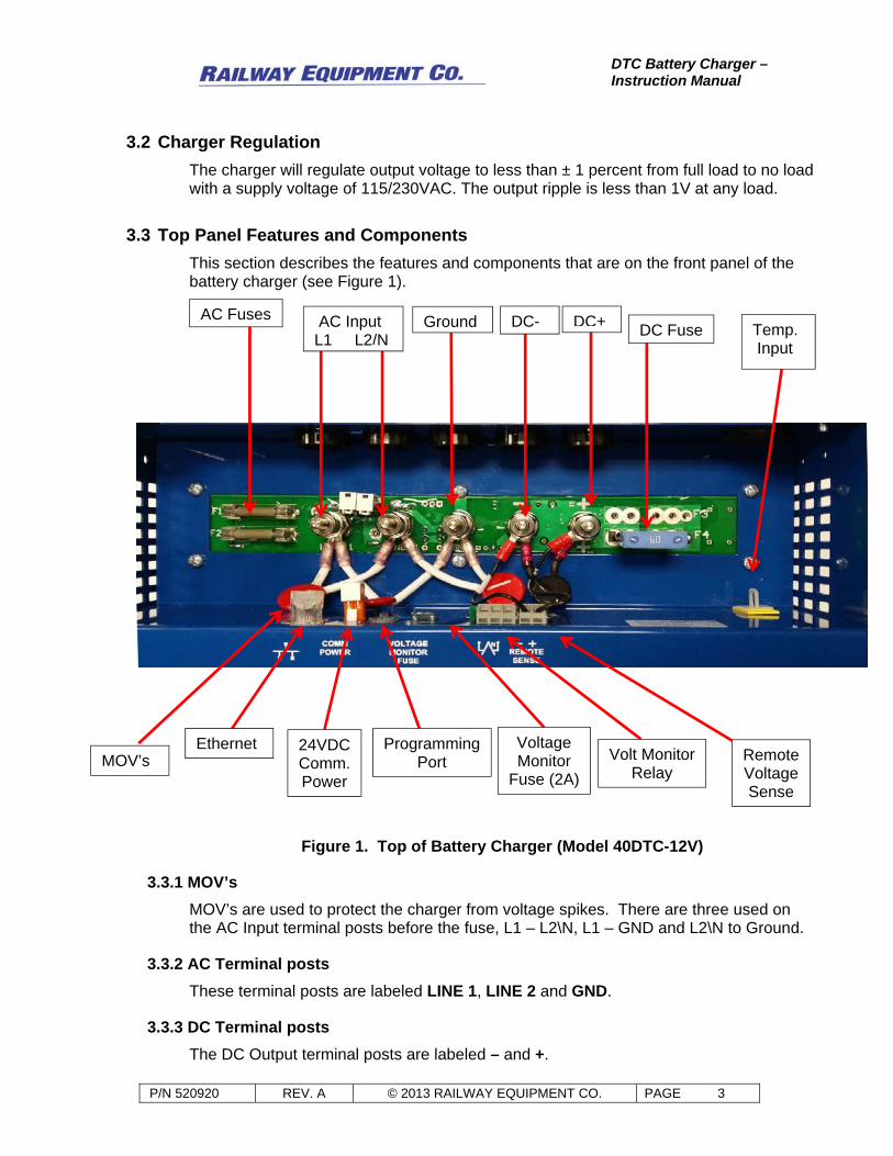
3.3 Top Panel Features and Components
This section describes the features and components that are on the front panel of the battery charger (see Figure 1).
Figure 1. Top of Battery Charger (Model 40DTC-12V)
3.3.1 MOV’s
MOV’s are used to protect the charger from voltage spikes. There are three used on the AC Input terminal posts before the fuse, L1 – L2\N, L1 – GND and L2\N to Ground.
3.3.2 AC Terminal posts
These terminal posts are labeled LINE 1, LINE 2 and GND.
3.3.3 DC Terminal posts
The DC Output terminal posts are labeled – and +.
AC Input L1 L2/N
Ground DC- DC+AC Fuses
Ethernet 24VDC Comm. Power
Programming Port
Temp. Input
Voltage Monitor
Fuse (2A)
Volt Monitor Relay
Remote Voltage Sense
DC Fuse
MOV’s
DTC Battery Charger – Instruction Manual
P/N 520920 REV. A © 2013 RAILWAY EQUIPMENT CO. PAGE 4
CAUTION: Be sure to observe correct polarity on battery and remote sense connections.
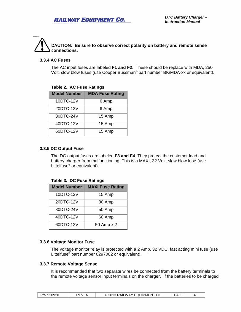
3.3.4 AC Fuses
The AC input fuses are labeled F1 and F2. These should be replace with MDA, 250 Volt, slow blow fuses (use Cooper Bussman® part number BK/MDA-xx or equivalent).
Table 2. AC Fuse Ratings
Model Number MDA Fuse Rating
10DTC-12V 6 Amp
20DTC-12V 6 Amp
30DTC-24V 15 Amp
40DTC-12V 15 Amp
60DTC-12V 15 Amp
3.3.5 DC Output Fuse
The DC output fuses are labeled F3 and F4. They protect the customer load and battery charger from malfunctioning. This is a MAXI, 32 Volt, slow blow fuse (use Littelfuse® or equivalent).
Table 3. DC Fuse Ratings
Model Number MAXI Fuse Rating
10DTC-12V 15 Amp
20DTC-12V 30 Amp
30DTC-24V 50 Amp
40DTC-12V 60 Amp
60DTC-12V 50 Amp x 2
3.3.6 Voltage Monitor Fuse
The voltage monitor relay is protected with a 2 Amp, 32 VDC, fast acting mini fuse (use Littelfuse® part number 0297002 or equivalent).
3.3.7 Remote Voltage Sense
It is recommended that two separate wires be connected from the battery terminals to the remote voltage sensor input terminals on the charger. If the batteries to be charged

DTC Battery Charger – Instruction Manual
P/N 520920 REV. A © 2013 RAILWAY EQUIPMENT CO. PAGE 5
are located more than 12 feet from the charger, there will be significant voltage drop through the wires.
3.3.8 Ethernet
This RJ45 Ethernet connection is used for accessing the charger, either via its internal webpage or via Sno-NET®. See section 8.4 and 9, of this manual for more information on configuration.
3.3.9 Comm Power
The Comm Power provides a Form C normally closed dry contact which can be used to cycle power to communications equipment. If the charger detects it hasn’t communicated to Sno-NET® in a predetermined amount of time, it will toggle this contact.
3.3.10 Programming Port
This is for manufacturers use only.
3.3.11 Voltage Monitor Relay
The voltage monitor provides a Form C dry contact relay which can be used to indicate when the battery voltage, current and temperature are either above or below the parameter settings.
The voltage monitor circuit is independent from the battery charger system and the AC power, and operates from the battery voltage.
The “normally open” contact is closed when the battery voltage, current and temperature is between the high and low settings.
The relay is rated for 2 Amps at 60 VDC, or 2 Amps at resistive loads. The mechanical contact life is 5,000,000 operations. Minimum inductive life @ .5 Amps, 12vdc is 50,000 times.
The voltage monitor can be used for an alarm by connecting the coil of an indication relay to the normally open relay contact terminals on the battery charger, with power for the relay supplied by others. The voltage monitor relay is protected with a 2 Amp, 32 VDC, fast acting mini fuse (use Littelfuse® part number 0297002 or equivalent).
3.3.12 Temperature Input
The temperature input provides the input for the remote temperature sensor cable assembly. This is used in conjunction with the Temperature Compensation Rate. By default Temperature Compensation is disabled, to enable, see 8.1.1 Basic Set Points.
When the temperature sensor is connected and Temperature Compensation is enabled, the battery charger will adjust the output voltage up or down depending on the temperature of the batteries and the Temperature Compensation Rate (see Table 4.)
Table 4 defines the temperature compensation rate when the battery charger adjusts the output voltage. If the remote temperature sensor is not used, the temperature compensation function will be fixed at 77°F.

DTC Battery Charger – Instruction Manual
P/N 520920 REV. A © 2013 RAILWAY EQUIPMENT CO. PAGE 6
Table 4. Temperature Compensation Rate
Battery Type Compensation
Mode Compensation
Slope Low Temp Limit High Temp Limit
Lead Acid 50% V/T 1.47mV/°F/cell 2.35 volts/cell@ +3°F 2.20 volts/cell@ +116°F
Lead Acid 100% V/T 3.0mV/°F/cell 2.35 volts/cell@ +37°F 2.20 volts/cell@ +95F
Ni-Cad 50% V/T 0.967mV/°F/cell No Limit No Limit
Ni-Cad 100% V/T 1.94mV/°F/cell No Limit No Limit
3.4 Front Panel Features
Figure 2. Front of Battery Charger (Model 40DTC-12V).
USB Port OLED Display Status LED’s

DTC Battery Charger – Instruction Manual
P/N 520920 REV. A © 2013 RAILWAY EQUIPMENT CO. PAGE 7
3.4.1 USB Port
The USB port is located on the front of the charger. It is used to access basic information and to configure the charger. An installable application is required and must be obtained from Railway Equipment Company. For more information see section 10 of this manual. A USB Type A male to Type B male cable is required.
3.4.2 Display
The display is a long life OLED display. It automatically dims after inactivity to extend the life of the display.
3.4.3 OK LED
The OK LED is on when the DC Output Voltage is within the HIGH VOLTAGE FAULT and LOW VOLTAGE FAULT settings (see section 8.1.1 for configuration).
Table 5. OK LED States
Description OK LED (Green) DC Output Voltage OK ON DC Output Voltage not OK OFF
3.4.4 FAULT LED
The FAULT LED has three different states, OFF, ON and FLASH. These are described in the table below.
Table 6. FAULT LED States
Description FAULT LED (Red) No Fault OFF Battery Temperature Fault ON DC Output Current Fault ON DC Output Voltage Fault ON Temp Comp On, No Temp Probe Connected
ON
AC Power Lost FLASH DC Output Fuse Blown FLASH DC Output Reverse Polarity FLASH
DTC Battery Charger – Instruction Manual
P/N 520920 REV. A © 2013 RAILWAY EQUIPMENT CO. PAGE 8
4 OPERATION
4.1 Front Panel Display and Push Button Controls
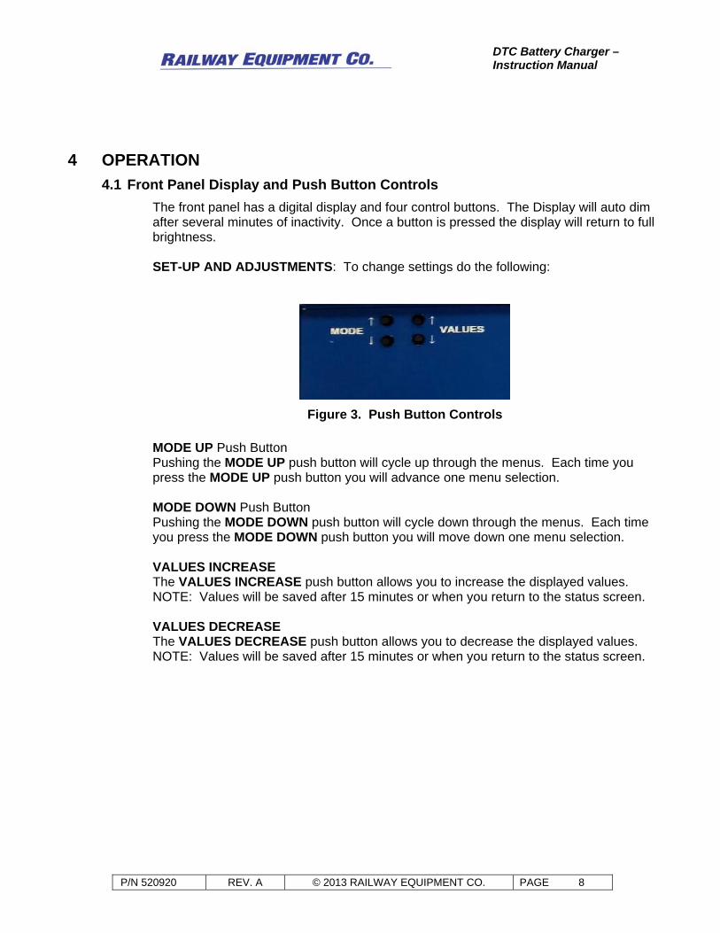
The front panel has a digital display and four control buttons. The Display will auto dim after several minutes of inactivity. Once a button is pressed the display will return to full brightness. SET-UP AND ADJUSTMENTS: To change settings do the following:
Figure 3. Push Button Controls
MODE UP Push Button Pushing the MODE UP push button will cycle up through the menus. Each time you press the MODE UP push button you will advance one menu selection. MODE DOWN Push Button Pushing the MODE DOWN push button will cycle down through the menus. Each time you press the MODE DOWN push button you will move down one menu selection. VALUES INCREASE The VALUES INCREASE push button allows you to increase the displayed values. NOTE: Values will be saved after 15 minutes or when you return to the status screen. VALUES DECREASE The VALUES DECREASE push button allows you to decrease the displayed values. NOTE: Values will be saved after 15 minutes or when you return to the status screen.

DTC Battery Charger – Instruction Manual
P/N 520920 REV. A © 2013 RAILWAY EQUIPMENT CO. PAGE 9
5 INSTALLATION
Warning: Before connecting power to the battery charger, make sure AC power is turned off. Connect AC power to the battery charger per label below the terminal posts.
5.1 Mounting
5.1.1 Shelf Mount
The charger is designed to allow enough air flow through the bottom of the charger when it is set on a shelf.
5.1.2 Wall Mount
Use the two-four keyed slots on the back of the charger for mounting to a wall.
5.1.3 Rack Mount
Optional Rack Mount brackets are available for purchase. These attached to the sides of the charger and allow for mounting at various different depths. 20DTC -P/N 31084708 30/40/60DTC - P/N31084709
5.2 Output Connections
CAUTION: WHEN CONNECTING WIRES FROM THE BATTERY TERMINALS TO THE CHARGER, VERIFY THE VOLTAGE POLARITY.
1. Connect the wires that will go between the battery and the DC Out terminal posts
labeled – and +. 2. Connect those wires to the battery posts. The charger should now power up from
the battery.
5.3 Setup
1. Setup the charger according to section 6 of this manual.
5.4 Input Connections
1. Connect the AC wires to the AC Input terminal posts. These terminal posts are labeled LINE 1, LINE 2/NUETRAL and GND.
2. Apply AC power to the charger.

DTC Battery Charger – Instruction Manual
P/N 520920 REV. A © 2013 RAILWAY EQUIPMENT CO. PAGE 10
5.5 Temperature Sensor Input
The Temperature Sensor is a Type K thermocouple wire. Plug the connector end into the temperature input on the Charger, and the other end can be placed between the individual cells of the battery bank.
5.6 Voltage Monitor Relay
Wire size should be minimum 18GA, maximum 16GA. This is a Form C dry contact relay with a Normally Open and Normally Closed set of contacts.
5.7 Remote Voltage Sense
This is done by removing the two pre-installed jumper wires from the remote voltage sense terminals and the DC output terminals and replacing them with wires from the battery terminals to the remote voltage sense terminals. If the remote voltage sensing function is not used, leave the two jumpers from remote voltage sense terminals to the DC output terminals connected.
CAUTION: WHEN CONNECTING WIRES FROM THE BATTERY TERMINALS TO THE CHARGER, VERIFY THE VOLTAGE POLARITY.
1. Disconnect the two jumper wires from the remote voltage sense terminals inside the wire terminal area and the DC battery output terminals.
NOTE: Before connecting the two wires to the battery terminals, make sure that the polarity is correct to avoid other equipment damage and prevent personnel injury.
2. Using minimum 18GA, maximum 16GA wire, connect two wires to the remote voltage sensing input terminals using a WAGO 210-719 terminal block operating tool on the terminal insertion tabs.
3. Ensuring proper polarity, connect the two wires to the battery terminals.

DTC Battery Charger – Instruction Manual
P/N 520920 REV. A © 2013 RAILWAY EQUIPMENT CO. PAGE 11
6 BASIC SETUP PROCEDURE 1. Use the MODE and VALUES buttons to navigate to the “SET POINTS” Screen. 2. Press the MODE UP button to display the “PASSWORD” Screen. 3. Enter a PASSWORD of 5 using the VALUES UP button. 4. Press the MODE UP button to go to the “USER LEVEL” Screen. 5. Select Basic for a user level using the VALUES UP\DOWN buttons. 6. Press the MODE UP button to go to the “BATTERY TYPE” Screen. 7. Select the Battery Type by using the VALUES UP\DOWN buttons. 8. Use the MODE UP button to go to the “NUMBER OF CELLS” Screen. 9. Select the number of cells using the VALUES UP\DOWN. 10. Use the MODE UP button to go to the “VOLTS PER CELL” Screen. 11. Select the voltage per cell using the VALUES UP\DOWN. 12. Use the MODE UP button to go to the “TEMPERATURE COMPENSATION”
Screen. 13. Select the either ON or OFF using the VALUES UP\DOWN. 14. Use the MODE UP button to go to the “CURRENT SETPOINT” Screen. 15. Select the maximum output current by using the VALUES UP\DOWN. 16. Use the MODE UP button to go to the “HIGH VOLTAGE FAULT SETPOINT”
Screen. 17. Select the voltage by using the VALUES UP\DOWN. 18. Use the MODE UP button to go to the “LOW VOLTAGE FAULT SETPOINT”
Screen. 19. Select the voltage by using the VALUES UP\DOWN. 20. Use the MODE UP and VALUES buttons to go back to the “STATUS” Screen. 21. Press the MODE UP button to now display the Voltage, Current and
Temperature Screen. This will save the settings that were just entered.

DTC Battery Charger – Instruction Manual
P/N 520920 REV. A © 2013 RAILWAY EQUIPMENT CO. PAGE 12
7 SPECIFICATIONS Table 7. General Specifications
Description Specification
Input Voltage
115/230VAC
50, 60 Hz
Voltage Regulation ± 1%
Voltage Ripple < 1 volt ripple, peak to peak at maximum output current
Operating Temperature
(0-95% non-condensing humidity) -40°F to +158°F -40°C to +70°C
Table 8. Model Specifications
Model No. Cells 115VAC Amps
230VAC Amps
Output Amps
Output Volts Width x Height x Depth Ship Weight
10DTC-12V
5–8 Lead Acid 5–12
NiCad 4.2
Amps 2.1
Amps 10
Amps
7 to 18.8 Volts
12.00 x 10.12 x 8.75 inches 40 lbs.
30.5 x 25.7 x 22.2 cm 18.1 kg
20DTC-12V
5–8 Lead Acid 5–12
NiCad 8.0
Amps 4.0
Amps 20
Amps
7 to 18.8 Volts
12.00 x 10.12 x 8.75 inches 40 lbs.
30.5 x 25.7 x 22.2 cm 18.1 kg
40DTC-12V
5–8 Lead Acid 5–12
NiCad
14
Amps 7.0
Amps 40
Amps
7 to 18.8 Volts
13.00 x 13.75 x 11.75 inches 52 lbs.
33.0 x 34.9 x 29.8 cm 23.6 kg
60DTC-12V
5–8 Lead Acid 5–12
NiCad
18
Amps 9.0
Amps 60
Amps
7 to 18.8 Volts
13.00 x 13.75 x 11.75 inches 74 lbs.
33.0 x 34.9 x 29.8 cm 33.6 kg
30DTC-24V
11–18 Lead Acid
19–26 NiCad 20Amps
10 Amps
30 Amps
24 to 42.5 Volts
13.00 x 13.75 x 11.75 inches 63 lbs.
33.0 x 34.9 x 29.8 cm 28.6 kg

DTC Battery Charger – Instruction Manual
P/N 520920 REV. A © 2013 RAILWAY EQUIPMENT CO. PAGE 13
8 USER MENUS The controller has 4 Menu Screens: 1. STATUS 2. FAULT HISTORY 3. SET POINTS 4. FACTORY DEFAULTS 5. ETHERNET SETTINGS (Available when a password of 85 is used) Menu Screen Selection: To select the desired Menu Screen, press the MODE UP or DOWN button until **** MENU SELECT **** is displayed, on line 1, and then use the INCREASE or DECREASE Value button to select the appropriate menu. Once the appropriate menu is selected, use the MODE UP or DOWN buttons to view the contents of the menu.
8.1 SET POINTS
NOTE: Use the Increase or Decrease Values button to change set point values. Under the SET POINTS menu, the user defined variables are entered. The parameter screens are:
USER LEVEL – The options are BASIC and ADVANCED. The BASIC user level allows any user to edit and display the minimal necessary menus and settings. The ADVANCED user level allows the user to display advanced menus and edit settings.
8.1.1 BASIC SET POINTS
PASSWORD – To change any parameter screen, use the increase button to enter the password of 5. To prevent others from changing parameters, return the password to 0 after making changes. Note: If the password is left at 5, it will automatically reset to 0 after ten minutes. BATTERY TYPE – The options are GENERIC LEAD ACID, GENERIC NI-CAD. Also included are presets for several specific brands, GNB Absolyte and SAFT SPL NI-CAD. NUMBER OF CELLS – For NI-CAD, 5-12 cells are selectable, for LEAD ACID its 5-8 cells. This is used to adjust the TOTAL VOLTS on the next screen. VOLTS PER CELL\TOTAL VOLTS – For NI-CAD the values range from 1.2-1.6VDC, for LEAD ACID it is 2-2.45VDC. For GNB Absolyte and SAFT SPL NI-CAD this value is fixed base on the manufacturers spec. TOTAL VOLTS is a calculation of NUMBER OF CELLS x VOLTS PER CELL. TEMPERATURE COMPENSATION – By default this is disabled, otherwise it can be enabled from this screen. Selecting a brand of battery (GNB, SAFT, etc.) from the “BATTERY TYPE” menu may enable this feature if that is the manufacturer’s suggested
DTC Battery Charger – Instruction Manual
P/N 520920 REV. A © 2013 RAILWAY EQUIPMENT CO. PAGE 14
use. See TABLE 4 for Temperature Compensation rates. CURRENT SET POINT – This is utilized to adjust the maximum output current limit. HIGH VOLTAGE FAULT – This adjustment is for setting the voltage level when the voltage monitor relay toggles for an over voltage fault. LOW VOLTAGE FAULT – This is used to set the voltage below which the voltage monitor relay changes state. As an example, it could be set for 10% below the normal battery output voltage, to trigger an alert before the voltage dropped to a point where it would no longer operate the equipment it was attached to.
8.1.2 ADVANCED SET POINTS
HIGH CURRENT FAULT – The parameter is the high amperage setting. The voltage monitor relay will toggle if the current is higher than the selected current. LOW CURRENT FAULT – The voltage monitor relay will toggle if the current is lower than the selected current. This should be set lower than the expected lowest current output, as when the batteries are fully charged and no equipment is running. HIGH BATTERY TEMP – This is for setting the temperature you wish to trigger a high battery temperature fault. If a high battery temperature fault occurs, the voltage monitor relay will toggle. LOW BATTERY TEMP – This is for setting the temperature you wish to trigger a low battery temperature fault. If a low battery temperature fault occurs, the voltage monitor relay will toggle. SELECT F OR C – This is used to choose the temperature units of measure. The choices are F for Fahrenheit and C for Celsius. CHARGER OVER TEMP PROTECTION – This cannot be disabled without calling tech support at (763-972-2200). When enabled, if the temperature of the battery charger becomes critical, it automatically decreases the output current limit so to reduce the potential of failure from overheating. BATTERY OVER TEMP PROTECTION – When enabled the charger will go to 50% of the set current output when the battery temp exceeds the HIGH BATTERY TEMP set point. If the battery temp exceeds the HIGH BATTERY TEMP set point by 10°F, then the charger will go to 0% output. The charger will go back to 100% output once the temperature has dropped 5°F below the HIGH BATTERY TEMP set point. EQUALIZATION – This is used to enable or disable the equalization charge function. If enabled, the remaining screens will appear when the MODE button is pushed. If equalization is disabled, the following 4 Equalization screens are hidden from view. EQ FREQUENCY IN DAYS (viewable if EQUALIZATION is enabled) – This is used to set the frequency at which equalization charge cycle will occur. It will increment in days.

DTC Battery Charger – Instruction Manual
P/N 520920 REV. A © 2013 RAILWAY EQUIPMENT CO. PAGE 15
EQUALIZATION RUN TIME IN xx HOURS (viewable if EQUALIZATION is enabled) – This sets the length of time the equalization charge cycle will run in hours. This can be set in 1 hour increments from 1 to 24. EQUALIZATION VOLTAGE SETPOINT (viewable if EQUALIZATION is enabled) – Set the voltage that you want the charger to produce for the equalization charge cycle. PRESS INCREASE TO RUN EQUALIZATION (viewable if EQUALIZATION is enabled) – By pressing the INCREASE button, the equalization cycle will begin. AC VOLTAGE TYPE – used for displaying what voltage the charger is setup for. This does not affect the performance of the charger. MY IP ADDRESS – Shows the chargers IP address. PROG REV & DATE – This displays the firmware revision level and the date that revision was released.
8.2 STATUS
The STATUS Screen can display BASIC or ADVANCED information based on what the USER LEVEL is set to.
8.2.1 BASIC
DC OUTPUT VOLTAGE DC OUTPUT CURRENT TEMP COMP AND BATTERY TEMP – displays whether or not TEMPERATURE COMPENSATION is enabled or disabled, and displays the temperature of the batteries if a temperature probe is installed. If there isn’t a temperature probe installed, this field will be blank.
8.2.2 ADVANCED
TOTAL OUTPUT POWER – This displays the total output power provided over time. RESETTABLE OUTPUT POWER – This is a resettable display of output power utilized over time. To reset this meter to zero, press the DECREASE button. OUTPUT WATTS – This displays the real time output power. TOTAL HOUR METER – This displays the total hours this battery charger has been operating. RESETTABLE HOUR METER – This displays the total hours this battery charger has been operating since this counter has been reset. To reset this counter to zero, press the DECREASE button.

DTC Battery Charger – Instruction Manual
P/N 520920 REV. A © 2013 RAILWAY EQUIPMENT CO. PAGE 16
AC VOLTAGE and AC CURRENT – displays the voltage that the charger is set up for, and also displays the current being used by the charger. AC FREQUENCY – This displays the input AC line frequency. POSITIVE CABLE RESISTANCE – This displays the resistance of the DC + cable between the charger and the battery. NEGATIVE CABLE RESISTANCE – This displays the resistance of the DC - cable between the charger and the battery. CIRCUIT BOARD TEMP – This displays the internal circuit board temperature.
8.3 FAULT HISTORY
OUTPUT RELAY/EQ RELAY – Shows the number of times the battery charger’s voltage monitor relay has cycled, and the number of times the battery charger has entered equalization.
POWER UP COUNTER – Shows the number of times the battery charger input power was turned on. DAYS COUNTER – Shows the total number of days the battery charger has been operating. TOTAL SECOND COUNTER – Shows the total number of seconds the battery charger has been operating. HIGH VOLTAGE FAULT COUNTER – Shows the number of times the battery charger voltage’s monitor relay has cycled do to a high voltage fault. LOW VOLTAGE FAULT COUNTER – Shows the number of times the battery charger voltage’s monitor relay has cycled do to a low voltage fault. HIGH CURRENT FAULT COUNTER – Shows the number of times the battery charger voltage’s monitor relay has cycled do to a high current fault. LOW CURRENT FAULT COUNTER – Shows the number of times the battery charger voltage’s monitor relay has cycled do to a low current fault. CHARGER OVER TEMP WARNING COUNTER – Show the number of instances a charger over temperature warning has occurred. CHARGER OVER TEMP FAULT COUNTER – Shows the number of times that a charger over temperature fault has occurred. BATTERY OVER TEMP WARNING COUNTER – Show the number of instances a battery over temperature warning has occurred.

DTC Battery Charger – Instruction Manual
P/N 520920 REV. A © 2013 RAILWAY EQUIPMENT CO. PAGE 17
BATTERY OVER TEMP FAULT COUNTER – Shows the number of times that a battery over temperature fault has occurred. AC POWER LOST COUNTER – Shows the number of occasions that the AC line voltage was lost (with the charger connected to a battery).
8.4 FACTORY DEFAULTS
FOR FACTORY DEFULTS PRESS DECREASE – This is to allow the user to return most settings to the original factory settings by pressing the DECREASE button. A password of 5 is required to change this setting.
8.5 ETHERNET SETTINGS
These can be configured by entering a password of 85 in the SET POINTS screen. WEB SERVER ADDRESS – Sno-NET® servers IP address, default of 208.42.179.9 DHCP IS ENABLED\DISABLED – if DHCP is enabled and a router is being used, the charger will obtain an IP address from it. With DHCP disabled an IP address needs to be entered on the MP IP ADDRESS screen. MY IP ADDRESS – if DHCP is enabled it will display the current IP address of the charger. If DHCP is disabled the IP address of the charger can be set on these screens. MY MASK – display and configure the subnet mask. MY GATEWAY – display and configure the gateway. PRIMARYDNSSERVER – display and configure the Primary DNS Server. SECOND DNSSERVER – display and configure the Secondary DNS Server. WEB REMOTE PORT – default of 49152, this is the port needed to communicate to Sno-NET®. WEB LOCAL PORT – if the charger is connected to a router, enter the port number of the router the charger is connected to.

DTC Battery Charger – Instruction Manual
P/N 520920 REV. A © 2013 RAILWAY EQUIPMENT CO. PAGE 18
9 HOSTED WEB PAGE Settings can be changed from the hosted web page as well as from the push buttons and display on the front of the charger.
9.1 Login
To login, look up the IP address under the SET POINTS - MY IP ADDRESS (SECTION 8.1.2 of this manual), and enter it in to your browser. The format should look like this http://***.***.***.***:50000. Make sure to add the port number of :50000 after the IP address. NOTE: If connecting directly to the charger from a computer, the computer and charger need to be on the same subnet. If the computer doesn’t support Ethernet crossover detection, a crossover Ethernet cable would be required.
9.2 Status page
Show the status of the battery charger.
Figure 4. System Status

DTC Battery Charger – Instruction Manual
P/N 520920 REV. A © 2013 RAILWAY EQUIPMENT CO. PAGE 19
9.3 Settings
Settings tab allow you to change the settings. The username is admin, and the password is 5.
Figure 5. Monitor Settings

DTC Battery Charger – Instruction Manual
P/N 520920 REV. A © 2013 RAILWAY EQUIPMENT CO. PAGE 20
10 USB APP The USB application allows configuration of the charger from a computer. An installable application is required and must be obtained from Railway Equipment Company. A USB Type A male to Type B male cable is required. The screenshots below show detailed images of the information that can be viewed and edited from each of the different tabs on the application.
10.1 Status Page
View the status of the charger, including temperatures, current, voltages, faults, etc.
Figure 6. Status Page

DTC Battery Charger – Instruction Manual
P/N 520920 REV. A © 2013 RAILWAY EQUIPMENT CO. PAGE 21
10.2 Connection Info Page
This page displays the IP configuration of the charger.
Figure 7. Connection Info Page

DTC Battery Charger – Instruction Manual
P/N 520920 REV. A © 2013 RAILWAY EQUIPMENT CO. PAGE 22
10.3 Web Configuration Page
This page allows you to edit the IP configuration of the charger.
Figure 8. Web Configuration Page

DTC Battery Charger – Instruction Manual
P/N 520920 REV. A © 2013 RAILWAY EQUIPMENT CO. PAGE 23
10.4 Settings Page
This page allows you to edit the configuration of the charger.
Figure 9. Settings Page