cr fpp 160 rev01 well control equipment
DESCRIPTION
speTRANSCRIPT

Company Rule CR FPP 160
Well control equipment
Exploration & Production Rev: 01 Date: 15/10/2003 Page: 2 of 86
This document is the property of Total. It must not be stored, reproduced or disclosed to others without written authorisation from the Company.
CR_FPP_160_REV01_Well_control_equipment.doc
Contents
1. RECAP OF RULES ............................................................................................... 7
2. FOREWORD ....................................................................................................... 232.1 INDICATOR................................................................................................................ 232.2 LIMITS and DEFINITIONS ......................................................................................... 232.3 GLOSSARY................................................................................................................ 24
3. BOP STACK CONFIGURATION PHILOSOPHY AND LIMITATIONS ............... 253.1 Position of the BSR .................................................................................................. 253.2 Position of the killing lines....................................................................................... 253.3 Position of the choke line for a 3 sets of rams BOP stack..................................... 263.4 Position of the choke lines for a 4 or more sets of rams BOP stack..................... 263.5 Stripping of the drill pipe string in the well with a 3 sets of rams BOP stack ...... 263.6 Stripping of the drill pipe string in the well with a 4 or more sets of rams
BOP stack.................................................................................................................. 273.7 Casing rams .............................................................................................................. 273.8 Shooting nipple......................................................................................................... 27
4. BOP REQUIREMENT ......................................................................................... 29
5. MAIN CONSIDERATIONS .................................................................................. 305.1 WORKING PRESSURE OF WELL CONTROL EQUIPMENT .................................... 305.2 MUD CROSSES......................................................................................................... 315.3 BOP OUTLETS .......................................................................................................... 315.4 BLIND RAMS ............................................................................................................. 315.5 SHEAR FUNCTION.................................................................................................... 315.6 CASING RAMS .......................................................................................................... 325.7 PIPE RAMS HANG-OFF CAPACITY ......................................................................... 325.8 RAM LOCKING DEVICES.......................................................................................... 335.9 DUAL COMPLETION................................................................................................. 335.10 COMPLETION ACCESSORIES ................................................................................. 335.11 BAG PREVENTERS................................................................................................... 335.12 RING GASKETS ........................................................................................................ 345.13 WELL CONTROL EQUIPMENT INFORMATION ON RIG.......................................... 345.14 BOP STACK INSTALLATION.................................................................................... 345.14.1 Surface BOP stack.................................................................................................... 355.14.2 Subsea BOP stack.................................................................................................... 355.15 H2S ENVIRONMENT .................................................................................................. 365.16 TEMPERATURE / FLUID COMPATIBILITY............................................................... 365.17 HP/HT WELLS ........................................................................................................... 37
Company Rule CR FPP 160
Well control equipment
Exploration & Production Rev: 01 Date: 15/10/2003 Page: 3 of 86
This document is the property of Total. It must not be stored, reproduced or disclosed to others without written authorisation from the Company.
CR_FPP_160_REV01_Well_control_equipment.doc
6. CONFIGURATION OF BLOW OUT PREVENTERS........................................... 386.1 SURFACE STACK CONFIGURATION ...................................................................... 386.1.1 MEWHP < or = 3 000 psi .......................................................................................... 386.1.2 MEWHP > 3 000 psi and < or = 5 000 psi ................................................................. 386.1.3 MEWHP > 5 000 psi and < or = 10 000psi ................................................................ 396.1.4 MEWHP>10 000 psi.................................................................................................. 396.2 SUBSEA BOP CONFIGURATION ............................................................................ 406.2.1 Single stack System.................................................................................................. 406.2.2 Two stack System..................................................................................................... 416.2.2.1 Large bore BOP stack........................................................................................... 416.2.2.2 Small bore stack MEWHP > or = 5 000 psi ........................................................... 41
7. CHOKE MANIFOLD, KILL & CHOKE LINES..................................................... 427.1 GENERAL .................................................................................................................. 427.2 KILL LINES ................................................................................................................ 437.2.1 Surface BOP............................................................................................................. 437.2.2 Subsea BOP ............................................................................................................. 437.3 CHOKE LINES : ......................................................................................................... 447.3.1 Surface BOP............................................................................................................. 447.3.2 Subsea BOP stacks .................................................................................................. 447.4 CHOKE MANIFOLD................................................................................................... 457.4.1 Number of chokes..................................................................................................... 457.4.2 General design and operating: .................................................................................. 45
8. BOP CONTROL SYSTEM................................................................................... 478.1 GENERAL .................................................................................................................. 478.2 HYDRAULIC CONTROL UNIT................................................................................... 478.2.1 ACCUMULATORS VOLUME AND PRESSURE ....................................................... 488.2.1.1 Surface BOP......................................................................................................... 488.2.1.2 Subsea BOP......................................................................................................... 498.2.2 CLOSING TIME PERFORMANCES ......................................................................... 508.2.3 PUMPS SYSTEM...................................................................................................... 518.3 CONTROL PANELS................................................................................................... 528.3.1 COMMON CONTROL PANELS................................................................................ 528.3.2 ROV INTERVENTION PANEL .................................................................................. 538.4 ACTUATION SYSTEM ............................................................................................... 538.5 PIPING ....................................................................................................................... 548.6 CONTROL FLUID ...................................................................................................... 558.7 DIVERTER CONTROL SYSTEM................................................................................ 55
9. DRILL STRING SAFETY VALVES ..................................................................... 569.1 EQUIPMENT IN DRILL STRING ................................................................................ 569.1.1 Kelly / Top drive system valves ................................................................................. 569.1.2 Drill string valves....................................................................................................... 569.2 EQUIPMENT READY ON RIG FLOOR ...................................................................... 579.2.1 Drill pipe safety valve ................................................................................................ 579.2.2 Upper drill string float valve ....................................................................................... 57

Company Rule CR FPP 160
Well control equipment
Exploration & Production Rev: 01 Date: 15/10/2003 Page: 4 of 86
This document is the property of Total. It must not be stored, reproduced or disclosed to others without written authorisation from the Company.
CR_FPP_160_REV01_Well_control_equipment.doc
10.MUD GAS SEPARATOR (MGS)......................................................................... 5810.1 MUD SEAL CONFIGURATION .................................................................................. 5810.2 VENT LINE................................................................................................................. 5910.3 OTHER EQUIPMENT................................................................................................. 5910.4 DEEP WATER : RISER GAS EVACUATION............................................................. 60
11.WELL CONTROL EQUIPMENT INSPECTION / CERTIFICATION /MAINTENANCE .................................................................................................. 61
11.1 GENERAL .................................................................................................................. 6111.2 RIG ACCEPTANCE.................................................................................................... 6211.3 PERIODIC INSPECTIONS ......................................................................................... 6211.4 MODIFICATIONS, CHANGES.................................................................................... 63
12.APPENDIX .......................................................................................................... 64Appendix 1: Drawings ....................................................................................................... 64SURFACE STACK MEWHP < or = 3 000 psi....................................................................... 65SURFACE STACK MEWHP < 3 000 psi and < or = 5 000 psi............................................ 66SURFACE STACK MEWHP > 5 000 psi AND < or = 10 000 psi ........................................ 67SURFACE STACK MEWHP > 10 000 psi .......................................................................... 68SUBSEA BOP STACK MEWHP < or = 10 000 psi ............................................................. 69LARGE BORE SUBSEA BOP STACK MEWHP < or = 3 000 psi ......................................... 70SUBSEA STACK MEWHP > 10 000 psi............................................................................... 71CHOKE MANIFOLD SCHEMATIC....................................................................................... 72HYDRAULIC CONTROL UNIT SCHEMATIC....................................................................... 75MUD GAS SEPARATOR SCHEMATIC ............................................................................... 76Appendix 2 : Shear rams................................................................................................... 77Appendix 3: Example of accumulator volume calculation............................................. 78A) Surface BOP stack .......................................................................................................... 78B) Subsea BOP stack .......................................................................................................... 80

Company Rule CR FPP 160
Well control equipment
Exploration & Production Rev: 01 Date: 15/10/2003 Page: 5 of 86
This document is the property of Total. It must not be stored, reproduced or disclosed to others without written authorisation from the Company.
CR_FPP_160_REV01_Well_control_equipment.doc
Reference documents
Unless otherwise stipulated, the applicable version of the reference documents listed below,including relevant appendices and supplements, is the latest revision published.
Standards
Reference TitleAPI SPEC 6AAPI SPEC 16AAPI RP 16EAPI RP 53API RP 64
Specifications for valves, Wellhead and Xmas tree equipmentDrilling and production equipmentDesign of control systems for drilling well control equipmentBlow Out prevention equipment systems for drilling wellsDiverter systems Equipment and Operations
Professional Documents
Reference TitleNot applicable
Regulations
Reference TitleNot applicable
Codes
Reference TitleNot applicable

Company Rule CR FPP 160
Well control equipment
Exploration & Production Rev: 01 Date: 15/10/2003 Page: 6 of 86
This document is the property of Total. It must not be stored, reproduced or disclosed to others without written authorisation from the Company.
CR_FPP_160_REV01_Well_control_equipment.doc
Other documents
Reference TitleCR FPP 130CR FPP 215CR FPP 165CR FPP 225CR FPP 230CR FPP 265CR FPP 170GS COR 170
Well barriers for drilling and workover operationsShallow gasWell Control equipment pressure testsCasing DesignWell Shut InWell Pressure IntegrityH2S PoliciesMaterials for sour service (upstream applications) Specificationsfor design
Other Total documents
Reference TitleNot applicable
Company Rule CR FPP 160
Well control equipment
Exploration & Production Rev: 01 Date: 15/10/2003 Page: 7 of 86
This document is the property of Total. It must not be stored, reproduced or disclosed to others without written authorisation from the Company.
CR_FPP_160_REV01_Well_control_equipment.doc
1. RECAP OF RULES
Blue color for rules to apply for offshore operations only, green color for rules to applyfor onshore operations only and black for rules for all situations.
Rule 1: All drilling and workover operations shall use a Blow Out Preventer as soonas the architecture allows to shut the well in until the well is plugged or acompletion with mechanical barriers is in place (refer to CR FPP 130).
In the event of programmed operations, without a Blow Out Preventer (i.e.drilling shallow reservoir with a diverting system) an appropriate riskassessment shall be carried out and documented.
Rule 2: The Working Pressure of all Well Control Equipment subject to well pressureshall be greater than or equal to the MEWHP of the operational phase duringwhich the equipment will be used.
Rule 3: The use of mud cross is not allowed on all BOP stacks when MEWH > 5 000psi.
Rule 4: Although API 6A allows 2" LP threaded connections on 5 000 psi WPequipment, welded flanges or hub connections are mandatory on all pressuresystems when MEWHP > 3000 psi.
Rule 5: Kill line outlet shall not be smaller than 2”1/16 nominal,
Choke line outlet shall not be smaller than 3"1/16 nominal.
Rule 6: Blind rams shall always been installed in the uppermost set of rams of anyBOP stack.
Company Rule CR FPP 160
Well control equipment
Exploration & Production Rev: 01 Date: 15/10/2003 Page: 8 of 86
This document is the property of Total. It must not be stored, reproduced or disclosed to others without written authorisation from the Company.
CR_FPP_160_REV01_Well_control_equipment.doc
Rule 7: For any operational phase where hydrocarbon bearing reservoirs areforeseen, shear function is mandatory on a BOP stack, except on onshoredevelopment wells when MEWP< or = 5000 psi, with low GOR oil reservoirs(<200m3/m3) and without H2S.
Adequate spacing above the pipe ram preventer is provided to shear the pipeabove the tool joint.
The hydraulic pressure required for shearing is within the accumulator’srating.
Rule 8: When running casing strings in open holes where hydrocarbon reservoirs arepresent or suspected, casing rams shall be installed or if not,� an appropriate risk assessment shall be carried out, documented and
included in the well drilling or work-over programme.� mitigation measures shall be taken (proper cross-over sub from casing to
drill pipes available on rig floor in case of surface BOP).
Rule 9: Ram type preventers shall have ram locking devices (mechanical orhydraulic) installed.
Rule 10: For dual completions, when the two strings are run simultaneously in a livewell (perforated or open hole) dual pipe rams are mandatory when thesealing is not compromise with completion accessories (e.g. cables, clamps,screens etc).
Rule 11: If completion accessories may compromise a shear, pipe or dual rams seal,then an appropriate risk assessment shall be carried out, documented andincluded in the well drilling or work-over programme to define appropriateprocedures and contingencies to mitigate this risk.
Rule 12: On a BOP stack with a WP below or equal to 5 000 psi, annular preventershall have the same WP rating as the BOP’s ram preventers.
On a BOP stack with a WP > 5 000 psi, annular preventers may be of a WPimmediately lower than the WP of the BOP’s rams preventers.
Company Rule CR FPP 160
Well control equipment
Exploration & Production Rev: 01 Date: 15/10/2003 Page: 9 of 86
This document is the property of Total. It must not be stored, reproduced or disclosed to others without written authorisation from the Company.
CR_FPP_160_REV01_Well_control_equipment.doc
Rule 13: Two 10 000 psi WP annular preventers shall be installed for drilling subseawells with MEWHP>10 000 psi.
Two annular preventers shall be installed for drilling deep or ultra-deep watersubsea wells with MEWHP> or = 5 000 psi.
Rule 14: New and clean ring gaskets shall be installed each time BOP componentsare re-assembled. Ring gasket shall not be reused. Only equipmentrecommended by BOP manufacturer shall be used for well control equipmentreplacement parts.
Rule 15: Clear and actual schematics of the choke manifold, stand pipe manifolds andBOP lay out shall be displayed next to the posters of well shut-in and controlprocedures in the Drill Master Cabin, at the choke manifold, at the BOPcontrol unit, at each BOP remote control panel, at the tool pusher and theCompany Man offices and at the mud logging unit.
Rule 16: For surface stack and for MEWHP up to and including 3 000 psi, theminimum BOP configuration shall be, as arranged from top to bottom (seefigure 1 in appendix 1):� One annular preventer.� Two ram type preventers with BR or BSR in the top cavity.� One kill line and one choke line connected below the lowermost set of
rams.
When working on “non-flowing” reservoirs, the stack can be reduced to oneannular and one single equipped with blind rams.
Company Rule CR FPP 160
Well control equipment
Exploration & Production Rev: 01 Date: 15/10/2003 Page: 10 of 86
This document is the property of Total. It must not be stored, reproduced or disclosed to others without written authorisation from the Company.
CR_FPP_160_REV01_Well_control_equipment.doc
Rule 17: For surface stack and for MEWHP above 3 000 psi up to and including to5 000 psi, the minimum BOP configuration shall be, as arranged from top tobottom (see figure 2 in appendix 1):� One annular preventer.
If no shear function is required:� Two ram type preventers with BR in the top cavity.� One kill line and one choke line connected below the lowermost set of
rams.If shear function is required:� Three singles or one double and one single ram type preventers with
BSR in the top cavity.� The upper kill line shall be installed below the uppermost set of rams
(BSR).� The lower kill line shall be connected below the lowermost set of rams.� The choke line shall enter the BOP stack above the lowermost set of pipe
rams.Stripping with the lowermost set of pipe rams is not allowed
Rule 18: For surface stack and for MEWHP above 5 000 psi up to and including10 000 psi, the minimum BOP configuration shall be, as arranged from top tobottom (see figure 3 in appendix 1):� One annular preventer.� Three singles or one double and one single ram type preventers.� The upper kill line shall be installed below the uppermost set of rams
(BSR).� The lower kill line shall be connected below the lowermost set of rams.� The choke line shall enter the BOP stack above the lowermost set of pipe
rams.
Stripping with the lowermost set of pipe rams is not allowed.
Redundancy of rams for each main DP string sizes is mandatory.
Rule 19: For surface stack and for MEWHP > 10 000 psi, the minimum BOP configurationshould be the same as for a 10 000 psi WP excepted that a four ram typepreventers BOP stack with one secondary choke line is mandatory. (see figure 4in appendix 1).
Company Rule CR FPP 160
Well control equipment
Exploration & Production Rev: 01 Date: 15/10/2003 Page: 11 of 86
This document is the property of Total. It must not be stored, reproduced or disclosed to others without written authorisation from the Company.
CR_FPP_160_REV01_Well_control_equipment.doc
Rule 20: For subsea single stack BOP stack and for subsea small bore BOP stack, theminimum BOP configuration shall be, as arranged from top to bottom (seefigure 5 in appendix 1):� One annular preventer.� Upper hydraulic connector (WP = annular preventer WP).� Four ram type preventers or two double ram type preventers.� Lower wellhead hydraulic connector (WP > or = ram type preventers WP)� One upper kill line hooked up below the BSR and one lower kill line
below the lowermost set of pipe rams, these lines having a common part.� Two choke lines with a common part.
Stripping with the lowermost set of pipe rams is not allowed.
Redundancy of rams for each main DP string sizes is mandatory
If temperature is excessive for VBR, the redundancy between ram preventerson the main DP string sizes shall be achieved by adding additional fixed piperam preventers below the top BSR.
Rule 21: For subsea large bore BOP stack, the minimum BOP configuration shall be,as arranged from top to bottom (see figure 6 in appendix 1):� One annular preventer.� Two ram type preventers.� One kill line hooked up below the BR or BSR.� One choke line hooked up below the lowermost set of PR.
Rule 22: Lines and manifold designed for dynamic loads shall be securely fastened.Flexible KL and CL high-pressure hoses longer than 4m and valvesassemblies at BOP outlets shall be supported to avoid the weak point initiateby the heavy weight of valves and flexible hoses.
All valves shall be marked with a colour code according to their normalposition while drilling.

Company Rule CR FPP 160
Well control equipment
Exploration & Production Rev: 01 Date: 15/10/2003 Page: 12 of 86
This document is the property of Total. It must not be stored, reproduced or disclosed to others without written authorisation from the Company.
CR_FPP_160_REV01_Well_control_equipment.doc
Rule 23: For surface and subsea BOP, in the case of a 3 or more sets of rams BOPstack, the line connected below the lowermost ram preventer shall not beused to evacuate an influx.
Rule 24: For subsea BOP, the choke manifold connection to the stand pipe manifoldshall be designed in such a way as to allow pumping through the KL withreturns through the CL, or vice versa but rule 22 still applies.
Rule 25: On surface BOP stacks, KL shall be at least 2” ID.
When MEWHP< 10 000 psi, each KL shall be equipped with two manual fullbore valves plus a check valve. In case no check valve is installed, minimumone of the two full bore valves shall be remotely operated.
When MEWHP> or =10 000 psi, each KL shall be equipped with two full-borevalves plus a check valve. One of the two valves shall be remotely operated.In case no check valve is installed, both full bore valves shall be remotelyoperated.
During operations, all valves shall be fully opened or fully closed (no valve inintermediate position) as per CR 230 well shut in.
The two kill lines can have a common part.
Rule 26: On subsea BOP stacks each KL shall be at least 3” ID and equipped with twofull bore remotely operated valves (fail safe closed). During operations, allvalves shall be fully opened or fully closed (no valve in intermediate position)as per CR 230 well shut in.
The kill lines have a common part.
Company Rule CR FPP 160
Well control equipment
Exploration & Production Rev: 01 Date: 15/10/2003 Page: 13 of 86
This document is the property of Total. It must not be stored, reproduced or disclosed to others without written authorisation from the Company.
CR_FPP_160_REV01_Well_control_equipment.doc
Rule 27: On surface BOP stacks, CL shall be at least 3’’ ID.
Two full-bore valves shall be installed on each CL. One of these two valvesshall be remotely operated.
During operations, all valves shall be fully opened or fully closed (no valve inintermediate position) as per CR 230 well shut in.
If two choke lines, they shall be connected independently to the chokemanifold and be completely isolated from the other by at least two valves.
"CHICKSAN" type sections are not allowed on choke lines. High-pressureflexible hoses (Coflexip type or equivalent) shall be used.
Rule 28: On subsea BOP stacks each CL shall be at least 3” ID and equipped with twofull bore remotely operated valves (fail safe closed). During operations, allvalves shall be fully opened or fully closed (no valve in intermediate position)as per CR 230 well shut in.
"CHICKSAN" type sections are not allowed on choke lines. High-pressureflexible hoses (Coflexip type or equivalent) shall be used.
The choke lines have a common part.
Rule 29: Number of chokes of the choke manifold:� 2 M.A.C. if MEWHP ≤ 3 000 psi� 2 M.A.C. + 1 R.O.C. if MEWHP> 3 000 and ≤ 10 000 psi� 1 M.A.C. + 2 R.O.C. if MEWHP> 10 000 psi

Company Rule CR FPP 160
Well control equipment
Exploration & Production Rev: 01 Date: 15/10/2003 Page: 14 of 86
This document is the property of Total. It must not be stored, reproduced or disclosed to others without written authorisation from the Company.
CR_FPP_160_REV01_Well_control_equipment.doc
Rule 30: The minimum size for choke manifold equipment is 3" nominal.
If two choke lines, two independent pressure sensors shall be available oneach line and be completely isolated from the other by at least two valves.
All chokes shall discharge directly into a at least 3’’ ID erosion nipple, at least3 ft long and 1’’1/4 thick.
Lead target flanges shall exist on the buffer chamber in front of all linescoming from the well.
The buffer chamber shall provide direct exits to the mud pit, verticaldegasser, horizontal flare (onshore) or burner boom(s) (offshore) andoverboard line.
At least one gate valve shall be installed downstream of each choke butahead of the buffer chamber. This valve may have a working pressure onestep down of the upstream side working pressure.
A bypass shall be provided from the choke line to the buffer chamber withoutpassing through the chokes. The two gate valves and the piping controllingthe bleed line shall have full rate working pressure of the BOP stackpreventers.
The installation, upstream of chokes, of a Glycol or equivalent injectionsystem is mandatory if hydrates formation is anticipated.
Rule 31: When remotely operated choke is mandatory, its control panel shall be nearthe Driller. It shall include, in addition to manometers (DP pressure, casingpressure) and choke monitor, the following:� an alarm set on Padm� A pump strokes totalizer.
The remotely operated choke shall be equipped with an emergency backupsystem in the event of primary energy supply shut down or failure (handpump or nitrogen).
Company Rule CR FPP 160
Well control equipment
Exploration & Production Rev: 01 Date: 15/10/2003 Page: 15 of 86
This document is the property of Total. It must not be stored, reproduced or disclosed to others without written authorisation from the Company.
CR_FPP_160_REV01_Well_control_equipment.doc
Rule 32: The hydraulic control unit with the master control panel shall be easilyaccessible, on the escape way and not at the rig floor, in a non-classified(non-hazardous) area. It shall be adequately protected against droppedobjects and fire.
Onshore, it shall be installed at least at 15 m from the wellhead.
RULE 33: For surface BOP, the total accumulator volume shall be equal to the volumerequired for the full closure and full opening of all preventers (rams and bag)plus all remote operated valves with a residual pressure which does not dropbelow the nitrogen pre-charge pressure plus 200 psi, the pumping systemsbeing off.
If shear rams are installed, the residual pressure of the accumulators afterhaving closed the hang-off pipe rams and sheared the drill pipe string shallbe at least equal to the manufacturer’s recommended pressure, the pumpingsystems being off.
This accumulator shall be split into at least two bottles banks. Each multi-bottle accumulator banks shall have valve for bank isolation.
Company Rule CR FPP 160
Well control equipment
Exploration & Production Rev: 01 Date: 15/10/2003 Page: 16 of 86
This document is the property of Total. It must not be stored, reproduced or disclosed to others without written authorisation from the Company.
CR_FPP_160_REV01_Well_control_equipment.doc
Rule 34: For subsea BOP, the total primary accumulators volume shall be equal toone and haft times the volume required for the full closure and opening of allpreventers (rams and bags ) plus all remote operated valves with a residualpressure which does not drop below the nitrogen pre-charge pressure plus200 psi, the pumping systems being out of service.In addition, the residual pressure of the total primary accumulators afterhaving closed the hang-off pipe rams and sheared the drill pipe string shallbe at least equal to the manufacturer’s recommended pressure, the pumpingsystems being off.
In case subsea accumulators are part of the primary system, the total primaryaccumulators volume shall include the volume of the subsea accumulatorson the BOP stack.
In case of dedicated subsea accumulators for emergency back up system,the volume of the dedicated subsea accumulators for emergency back upsystem shall be equal to one and half times the volume required to close thehang-off pipe rams, to shear the drill pipe string, to close a second set of piperams, to activate the ram locks and disconnect the lower marine riserpackage with a residual pressure which does not drop below the nitrogenpre-charge pressure plus 200 psi, the pumping systems being off.In addition, the residual pressure of the dedicated subsea accumulators foremergency back up system after having closed the hang-off pipe rams andsheared the drill pipe string shall be at least equal to the manufacturer’srecommended pressure, the pumping systems being off.
The surface accumulator shall be split into at least four bottles banks.Subsea accumulators (dedicated to the emergency back up system or part ofthe primary accumulators), if any, shall be split into at least two bottles banks.Each subsea multi-bottle accumulator banks shall have ROV operated valvesfor bank isolation.
Rule 35: If emergency back up system (acoustic, dead man system or equivalent) isinstalled, it should have its own dedicated and independent pilot circuit. Thededicated subsea accumulators for emergency back up system shall beconnected in such a way as fluid is not lost if the supply line(s) from the rig iscut.
In case of emergency back up system, dedicated subsea accumulatorsinstalled on the BOP stack are mandatory. These dedicated subseaaccumulators providing energy to the pilot and the power circuit of theemergency back up system are not used during primary BOP functions.
Company Rule CR FPP 160
Well control equipment
Exploration & Production Rev: 01 Date: 15/10/2003 Page: 17 of 86
This document is the property of Total. It must not be stored, reproduced or disclosed to others without written authorisation from the Company.
CR_FPP_160_REV01_Well_control_equipment.doc
Rule 36: For surface installations, the BOP control system shall be capable of closingeach ram BOP within 30 seconds. Closing time shall not exceed 30 secondsfor annular BOPs smaller than 18 ¾ inches nominal bore and 45 seconds forannular preventers of 18 ¾ inches nominal bore and larger. Response timefor choke and kill valves (either open or close) shall not exceed the minimumobserved ram BOP close response time.
For subsea installations, the BOP control system shall be capable of closingeach ram BOP in 45 seconds or less. Closing time shall not exceed 60seconds for annular BOPs. Response time for choke and kill valves (eitheropen or close) shall not exceed the minimum observed ram BOP closeresponse time. Time to unlatch the lower marine riser package shall notexceed 45 seconds.
The required pressure for shearing the DP shall be obtained in less than twominutes.
Rule 37: For the pump system of the BOP control system the minimum requirement istwo pump systems, driven by independent power sources:� either 1 electrical pump system plus one air pump system� or 2 electrical pump systems completely independent regarding the
electric network (cables, distribution boxes)In addition, each pumping system shall be designed to fulfil, independently ofthe other source, the most stringent case:� Either charging of the accumulator from the pre-charge pressure to the
rating pressure of the accumulator in less than 15 minutes,� Or closure of the annular preventer on drill pipe with correct sealing
pressure and the opening of the hydraulic choke valve in less than 2minutes.
In case of two electrical pump system one electrical pump system shall bepowered by the emergency generator.
Pumping shall start automatically when pressure in the accumulator dropsbelow 90% of the maximum operating pressure.
Company Rule CR FPP 160
Well control equipment
Exploration & Production Rev: 01 Date: 15/10/2003 Page: 18 of 86
This document is the property of Total. It must not be stored, reproduced or disclosed to others without written authorisation from the Company.
CR_FPP_160_REV01_Well_control_equipment.doc
Rule 38: Any surface BOP stack installation shall have at least one air or electricremote control panel located near the driller's position.
Offshore a second control panel shall be installed in a safe area (toolpusher’s office or on the tender in the case of platform tender assistedmode).
For subsea BOP, all control panels shall be electric and shall display allunderwater functions. Indication of control fluid flow is required on eachpanel.
Each control panel shall clearly show “open” and “closed” positions on avisual display in line with the BOP stack installed. It shall be adequatelyprotected against fluid projection.
Each control panel shall include a master shut-off valve, controls for theregulator valves (general manifold and annular specific one) and control forthe by-pass valve. They shall be fitted with main alarms indicating lowaccumulator pressure, low level in control fluid tank and lack of power supply.
A "Think first" flap shall be set as a precaution over each BSR push-buttonon each control panel
The master control panel on the hydraulic control unit shall have a by-passvalve( by-passing the pressure regulator) to allow to have the full pressure ofaccumulators at the master control panel.
Rule 39: In deep and ultra-deep waters ROV intervention panel is mandatory
Rule 40: When ROV intervention is mandatory, ROV emergency functions are thefollowing:� On the LMRP:
- LMRP connector primary and secondary unlocking- Choke and kill stabs primary and secondary unlocking.
� On the BOP stack:- Closure of hang off pipes rams and shear rams- Ram locking devices
- Wellhead connector primary and secondary unlocking

Company Rule CR FPP 160
Well control equipment
Exploration & Production Rev: 01 Date: 15/10/2003 Page: 19 of 86
This document is the property of Total. It must not be stored, reproduced or disclosed to others without written authorisation from the Company.
CR_FPP_160_REV01_Well_control_equipment.doc
Rule 41: An Emergency Battery Pack (UPS) shall be available to supply electric powerto operate the BOP control system, when electrical type, for up to 24 hours.The battery pack shall supply power to the electric control panels.
An Emergency Air Supply shall be available to supply air power to operatethe BOP control system, when air operated type. In that case it shall supplythe air remote control panels and air driven pressure regulators if theseregulators are not of fail safe type.
Rule 42: For subsea BOP the link between the hydraulic control unit and the BOPstack shall be via a dual hydraulic or Electro-hydraulic cable and/or hosesystem providing 100 % redundancy of control for all functions of the BOP(yellow and blue pods). Total length of the flexible control cables and hosesshall be 90 m (300 feet) greater than the maximum water depth for which thesystem is to be used
Rule 43: An emergency back up control system (acoustic, dead man system orequivalent) shall be installed for Dynamic Positioning with the followingfunctions:� close the hang-off set of pipe rams� shear the drill pipe� close a second set of pipe rams� activate the ram locks� disconnect the lower riser marine package
For anchored rigs, an additional acoustic control system is recommended incase of high risk operation (severe environment, high pressure target).
Rule 44: High-pressure steel pipe or high-pressure fire-resistant control hoses with aworking pressure at least equal to the accumulator rating pressure shall beused. The nominal diameter shall be 1’’ minimum, so as to reduce pressurelosses and consequently BOP closing time.
For flexible parts, the hoses shall be steel wrapped (Coflexip type orequivalent) to provide greater resistance to fire and improved durability.Sharp bends on hoses shall absolutely be avoided.
Company Rule CR FPP 160
Well control equipment
Exploration & Production Rev: 01 Date: 15/10/2003 Page: 20 of 86
This document is the property of Total. It must not be stored, reproduced or disclosed to others without written authorisation from the Company.
CR_FPP_160_REV01_Well_control_equipment.doc
Rule 45: For surface BOPs, fluid storage capacity on the rig shall be at least twice theworking volume of the accumulators.
For subsea BOPs, automatic proportioning equipment is required for solubleoil. Its capacity shall be greater than the total flow-rate produced by the twopump systems.
The characteristics of control fluid (including cleanliness) shall be in line withthe recommendation of the manufacturer and shall be suitable for workcarried out in cold areas if applicable.
Rule 46: In case of kelly, two valves are installed at the top and bottom end of thekelly:� The upper Kelly valve. This valve will be closed first if necessary.� The lower Kelly valve. This valve allows installation of the circulating
head or of the drop-in check valve in drill pipes.
In case of Top drive, there will be two IBOP safety valves:� The upper safety valve remotely operated. This valve will be closed first if
necessary� The lower safety valve manually operated.
Both the lower and upper Kelly and IBOP valves will have as a minimum thesame pressure rating as the BOP.
Rule 47: A DICV sub and a float valve near the bit shall be incorporated in a drill orwork string on:
� All drilling phases of exploration and delineation wells,� Before entering the reservoir on development wells,� As a protection against shallow gas influx.
On a floating rig, a DICV sub shall always be incorporated in a drill or workstring.
Rule 48: One spare drill pipe safety valve with lifting device shall be permanently kepton the drill floor with cross-over adapted to string pipes in use.
Company Rule CR FPP 160
Well control equipment
Exploration & Production Rev: 01 Date: 15/10/2003 Page: 21 of 86
This document is the property of Total. It must not be stored, reproduced or disclosed to others without written authorisation from the Company.
CR_FPP_160_REV01_Well_control_equipment.doc
Rule 49: Each drilling or work over rig shall be provided with an atmospheric de-gasser. Minimum requirements are:� 10 ft Mud seal height� 8’’ nominal pipe for gas exhaust� a siphon breaker not tied into the vent line
Rule 50: A Well Control Equipment log book is mandatory on each rig and will be partof the site Safety Register
It is the drilling and completion supervisor’s role to periodically verify that theWell Control Equipment log book is issued, available and up to date.
The rig Well Control Equipment log book is constituted with:� Certification package by the manufacturer or an approved third party with
API monogram. API manufacturing documentation, NACE certificationincluding raw material traceability. Manufacturers must provide fulltraceability of Well Control Equipment and spare parts.
� Commissioning Well Control Equipment inspection report and action plan� inspection reports and following action plans after periodic inspections of
Well Control Equipment� any inspection reports after repair or change of equipment.� repair / change log book. Dates, technical reason for change, part
number and working limitations of installed components (pressure,temperature rating, OBM compatibility, etc) shall be recorded andapproved by the rig manager.
� maintenance log book.
Rule 51: A new certification is required if, at the rig acceptance stage, the BOPdocuments file (previous certificates, log book, etc) is missing or badlycompleted.A complete BOP stack dismantling and inspection shall be carried out forcertification when control equipment has been stacked for a period equal toor greater than 6 monthsAt the rig acceptance stage, periodic inspections will be checked

Company Rule CR FPP 160
Well control equipment
Exploration & Production Rev: 01 Date: 15/10/2003 Page: 22 of 86
This document is the property of Total. It must not be stored, reproduced or disclosed to others without written authorisation from the Company.
CR_FPP_160_REV01_Well_control_equipment.doc
Rule 52: A complete BOP stack dismantling and inspection shall be carried out forcertification if:� equipment is in continuous use for more than 5 years� equipment was subject to abnormal conditions (excessive shock, fire,
etc).
Rule 53: A new certification is required in the case of repair inducing hot work
Company Rule CR FPP 160
Well control equipment
Exploration & Production Rev: 01 Date: 15/10/2003 Page: 23 of 86
This document is the property of Total. It must not be stored, reproduced or disclosed to others without written authorisation from the Company.
CR_FPP_160_REV01_Well_control_equipment.doc
2. FOREWORD
2.1 INDICATOR
Rule which needs derogation
2.2 LIMITS and DEFINITIONS
This rule gives configuration, rating and maintenance policy for well closure systemsinvolved in drilling, work-over and well testing. Diverting systems are mentioned but aremore specifically detailed in the CR FPP 215 ‘’Shallow gas’’.
Efficiency and reliability are required for this mechanical barrier which is the final barrierin place if the hydraulic barrier is damaged.
The minimum requirements are dictated by the API RP 53 standard (with reference toRP 16E). This rule retains the main points of this standard but aims to highlight anyspecific points that diverge from API or are more stringent. Points not addressed shallbe in accordance with the API standard.
Equipment testing policy is defined in CR FPP 165 “Well Control equipment: pressuretests”.
“Deep water” is defined as the water depths included between 300 meters and 1000meters.
“Ultra –deep water” is defined as the water depths greater than 1000 meters.
“HP” (high pressure) wells are the wells with MEWHP above 10000 psi.
“HP/HT” (high pressure/high temperature) wells are the wells with MEWHP above10000 psi and bottom hole temperature above 350°F.

Company Rule CR FPP 160
Well control equipment
Exploration & Production Rev: 01 Date: 15/10/2003 Page: 24 of 86
This document is the property of Total. It must not be stored, reproduced or disclosed to others without written authorisation from the Company.
CR_FPP_160_REV01_Well_control_equipment.doc
2.3 GLOSSARY
BOP Blow Out PreventerBR Blind RamsBSR Blind Shear RamsCL Choke LineCV Check ValveDICV = DIBPV Drop In Check Valve or Drop In Back Pressure ValveDP Drill PipeIBOP Internal BOPKL Kill LineLMRP Lower Marine Riser PackageMAC Manual ChokeMEWHP Maximum Expected Wellhead PressureMGS Mud Gas SeparatorML Mud LinePadm Admissible PressurePR Pipe RamsROC Remotely Operated ChokeSIMOPS Simultaneous OperationsVBR Variable Bore RamsXO Cross Over Sub

Company Rule CR FPP 160
Well control equipment
Exploration & Production Rev: 01 Date: 15/10/2003 Page: 25 of 86
This document is the property of Total. It must not be stored, reproduced or disclosed to others without written authorisation from the Company.
CR_FPP_160_REV01_Well_control_equipment.doc
3. BOP STACK CONFIGURATION PHILOSOPHY AND LIMITATIONS
3.1 Position of the BSR
The BSR installation in the lowermost cavity could be considered as the most effectiveposition for an ultimate barrier. But the major drawback of this position is to lose the drillstring when the BSR are activated. As we want to keep the possibility of conventional wellcontrol after shearing the drill string, the drill pipe has to be hung-off prior to shearing andconsequently the BSR can not be located in the lowermost cavity.
As we consider the outlets of the choke lines on the BOP stack as a weak point (possiblewash out with uncontrolled fluid) which could lead to a catastrophic consequence, wewant, when possible, no choke lines located below the lowermost set of pipe rams whichmust be kept as the last barrier. Consequently, in the case of a 3 or more sets of ramsBOP stack, the outlets of all the choke lines have to be located above the lowermost set ofpipe rams.
As the choke line has to be located below the set of pipe rams used to hang-off beforeshearing, the only possible position of the BSR for a 3 sets of rams BOP stack is in the topcavity.
For harmonisation reason the BSR is located in the top cavity of a 4 sets of rams BOPstack.
Note: The wellbore pressure can cause cases where the pipe cannot be sheared(operating pressure must overcome the shearing force plus the well bore pressure). Theposition of BSR on top of the BOP stack is helpful as, when the drill pipe is hung-off, thebleed-off of the wellbore is possible before shearing which is not possible when the BSRare at the lowermost position of the BOP stack.
3.2 Position of the killing lines
As we want to have the possibility to bull-head in the well when the lowermost rams areclosed one kill line must be located below the lowermost set of rams. The risk of wash outof this kill line is very low as, always, a clean and controlled fluid is pumped through thisline. The consequence is that the line connected below the lowermost ram preventer shallnever be used to evacuate an influx.
After hanging-off and shearing the drill pipe, we want to kill the well by circulation down thedrill string with return through the choke line and without dismantling the set up. Therefore,the upper kill line shall be connected just below the BSR.
Company Rule CR FPP 160
Well control equipment
Exploration & Production Rev: 01 Date: 15/10/2003 Page: 26 of 86
This document is the property of Total. It must not be stored, reproduced or disclosed to others without written authorisation from the Company.
CR_FPP_160_REV01_Well_control_equipment.doc
3.3 Position of the choke line for a 3 sets of rams BOP stack
As already mentioned the choke line must not be located below the lowermost set of piperams.The choke line has to be located below a set of pipe rams in order to circulate through thechoke manifold when closed on pipe rams. For that reason, the choke line cannot belocated below the BSR in the top cavity. Consequently the only possible position is belowthe middle pipe rams.
The corollary is that the well cannot be circulated conventionally or volumetrically killedwhen shut in on the lowermost set of pipe rams.
3.4 Position of the choke lines for a 4 or more sets of rams BOP stack
As this configuration is for high risk wells and / or when a tapered drill string is used 2choke lines are mandatory to increase the reliability and the flexibility of the set up.
As already mentioned no choke line can be located below the lowermost set of pipe rams.
At least one choke line must be located below a set of pipe rams in order to circulatethrough the choke manifold when closed on this set of pipe rams.
3.5 Stripping of the drill pipe string in the well with a 3 sets of rams BOP stack
As we want to keep the lowermost set of rams as a mean of shutting the well if othercomponent of the BOP stack fails, these rams shall never be subjected to the wear andstress of stripping operations.
Therefore, the minimum configuration for a 3 sets of rams BOP stack (with one choke linebelow the intermediate set of pipe rams) only allows stripping of the drill pipe stringthrough the annular preventer and consequently, the installation of a stripping bottle on theannular preventer is recommended.
If stripping between annular preventer and the intermediate set of pipe rams is wanted asecond choke line should be connected above the intermediate pipe rams.
When rams to rams stripping is a requirement for a high risk well, an additional set of piperams and a second choke line shall be installed.
Company Rule CR FPP 160
Well control equipment
Exploration & Production Rev: 01 Date: 15/10/2003 Page: 27 of 86
This document is the property of Total. It must not be stored, reproduced or disclosed to others without written authorisation from the Company.
CR_FPP_160_REV01_Well_control_equipment.doc
3.6 Stripping of the drill pipe string in the well with a 4 or more sets of rams BOPstack
As mentioned above, a second choke line is a requirement on a 4 or more sets of ramsBOP stack. If rams to rams stripping is a requirement, the position of the two choke linesand the spacing between rams will be adjusted to allow rams to rams stripping on the maindrill pipe string (s). The lowermost set of rams will never be used for stripping.
For subsea BOP, if rams to rams stripping is a requirement, the position of the upper killline (as this line could be used as a choke line in subsea BOP), the position of the twochoke lines and the spacing between rams will be adjusted to allow rams to rams strippingon the main drill pipe string(s). The lowermost set of rams will never be used for stripping.
Note: For subsea BOP, rams to rams stripping is often unpractical.
3.7 Casing rams
Consideration for the use of casing rams will be dependent on the inherent risks of thesection to be cased:
� For simple cases, to be validated by the drilling manager with a risk assessment, weconsider that:
- the bag preventer is capable to treat a well flow during running down a casingstring
- and, if the situation worsen, the use of a proper cross-over sub will allow to shutin the well with the pipe rams
� For the other cases, the use of casing rams is mandatory. The pressure test of thecasing rams themselves at the MEWHP is strongly recommended. (Note: Theposition of the BSR in the top cavity allows the BOP body test at the MEWHP).
3.8 Shooting nipple
The pack-off assembly generally used on wire line BOP above the shooting nipple issealing on a non moving stranded cable up to 2 500 psi. If the cable is moved, the sealingrubbers of the pack-off will be destroyed.
Normal procedure when killing a well during logging does not allow to move the cable.Some special equipment is available for controlling the well with the cable moving butgenerally not on the rig.
Consequently, the shooting nipple is to be used on well with a MEWHP below 2 500 psiand without H2S and our recommendations are:
Company Rule CR FPP 160
Well control equipment
Exploration & Production Rev: 01 Date: 15/10/2003 Page: 28 of 86
This document is the property of Total. It must not be stored, reproduced or disclosed to others without written authorisation from the Company.
CR_FPP_160_REV01_Well_control_equipment.doc
� For logging operations, the shooting nipple is not mandatory. Firstly, a hydraulicwire cutter is available on rig floor in order to cut the wire if needed and secondly,BSR are installed in the BOP stack in case the hydraulic wire cutter fails.Moreover, the stability of the well is ensured before starting POOH.
� For perforations operations, two cases exist:- On wells with a MEWHP below 2 500 psi and without H2S, a shooting nipple is
rigged up in the annular preventer and chained to avoid any upward movement.If any problem, the cable is stopped and the pack-off activated to allow to kill thewell.
- On wells with H2S or with a MEWHP above 2 500 psi, the use of a shootingnipple is forbidden.
Company Rule CR FPP 160
Well control equipment
Exploration & Production Rev: 01 Date: 15/10/2003 Page: 29 of 86
This document is the property of Total. It must not be stored, reproduced or disclosed to others without written authorisation from the Company.
CR_FPP_160_REV01_Well_control_equipment.doc
4. BOP REQUIREMENT
Rule 1: All drilling and workover operations shall use a Blow Out Preventer as soonas the architecture allows to shut the well in until the well is plugged or acompletion with mechanical barriers is in place (refer to CR FPP 130).
In the event of programmed operations, without a Blow Out Preventer (i.e.drilling shallow reservoir with a diverting system) an appropriate riskassessment shall be carried out and documented.
The use of a diverter system as a BOP on exploration wells is not recommended. Evenif the rig is equipped with a 2000 psi diverter unit, this cannot be considered as a validBOP. A compatible 2000/3000 psi BOP stack will be used as soon as closure of the wellis possible.
Company Rule CR FPP 160
Well control equipment
Exploration & Production Rev: 01 Date: 15/10/2003 Page: 30 of 86
This document is the property of Total. It must not be stored, reproduced or disclosed to others without written authorisation from the Company.
CR_FPP_160_REV01_Well_control_equipment.doc
5. MAIN CONSIDERATIONS
5.1 WORKING PRESSURE OF WELL CONTROL EQUIPMENT
The Well Control Equipment is one of the main components of the structural barrierwhen drilling or completing a well. The rating of the Well Control Equipment will be inaccordance with the MEWHP of the operational phase during which the equipment willbe used.
Refer to CR FPP 225 “Casing design” – chapter 8.3.3- for MEWHP evaluation.Constraints due to special pumping operations (acid job, stimulation, etc.) will be takeninto consideration if foreseen.
For exploration wells, the maximum formation pressure gradients given by the geologistdepartment will be taken into account for the MEWHP estimation (basically made on awell full of gas).MEWHP should not be confused with Padm. Padm is the wellheadpressure limit based on the weakest point of surface equipment, casing and casingshoe.
Well Control equipment could be used at its API WP unless any de-rating applies, forexample: temperature limitations, specific points mentioned in inspection reports (wear,existing repair, etc) or H2S in fluids.
The WP of an equipment is equal to its API WP minus any de-rating:WP= API WP * K with K= de-rating ratio.
Rule 2: The Working Pressure of all Well Control Equipment subject to well pressureshall be greater than or equal to the MEWHP of the operational phase duringwhich the equipment will be used.
For deep or ultra-deep water stacks, water pressure will be ignored when calculating thesubsea well control equipment working pressure.
Six working pressure categories are given by API:� 2,000 psi/138 bar� 3,000 psi/207 bar� 5,000 psi/345 bar� 10,000 psi/689 bar� 15,000 psi/1035 bar� 20,000 psi/1379 bar
Company Rule CR FPP 160
Well control equipment
Exploration & Production Rev: 01 Date: 15/10/2003 Page: 31 of 86
This document is the property of Total. It must not be stored, reproduced or disclosed to others without written authorisation from the Company.
CR_FPP_160_REV01_Well_control_equipment.doc
5.2 MUD CROSSES
The use of double and/or triple stage BOPs with lateral outlets below the rams allows:� the elimination of mud cross� the reduction of stack heights� the reduction of the number of flanges or bolted clamps (potential leak points)
The use of mud cross on all BOP stacks is not recommended. However, mud cross isallowed on surface stacks when MEWHP < or equal to 5 000 psi when pipe rampreventers are not fitted with lateral outlets
Rule 3: The use of mud cross is not allowed on all BOP stacks when MEWH > 5 000psi.
If necessary for adequate spacing between rams, spools could be used.
5.3 BOP OUTLETS
Rule 4: Although API 6A allows 2" LP threaded connections on 5 000 psi WPequipment, welded flanges or hub connections are mandatory on all pressuresystems when MEWHP > 3000 psi.
Rule 5: Kill line outlet shall not be smaller than 2”1/16 nominal,
Choke line outlet shall not be smaller than 3"1/16 nominal.
5.4 BLIND RAMS
Rule 6: Blind rams shall always been installed in the uppermost set of rams of anyBOP stack.
5.5 SHEAR FUNCTION
Rule 7: For any operational phase where hydrocarbon bearing reservoirs areforeseen, shear function is mandatory on a BOP stack, except on onshoredevelopment wells when MEWP< or = 5 000 psi, with low GOR oil reservoirs(<200m3/m3) and without H2S.
Company Rule CR FPP 160
Well control equipment
Exploration & Production Rev: 01 Date: 15/10/2003 Page: 32 of 86
This document is the property of Total. It must not be stored, reproduced or disclosed to others without written authorisation from the Company.
CR_FPP_160_REV01_Well_control_equipment.doc
Adequate spacing above the pipe ram preventer is provided to shear the pipeabove the tool joint.
The hydraulic pressure required for shearing is within the accumulator’srating.
The BSR is capable of shearing the strongest drill pipe/tubing in use on therig under no-load conditions, and subsequently provide a proper seal.
If necessary, BOP’s are upgraded by using large bore bonnets, extra large bore bonnets,booster units and DS shear blind rams (greater cutting efficiency).
5.6 CASING RAMS
Consideration for the use of casing rams will be dependent on the inherent risks of thesection to be cased.
Rule 8: When running casing strings in open holes where hydrocarbon reservoirs arepresent or suspected, casing rams shall be installed or if not,� an appropriate risk assessment shall be carried out, documented and
included in the well drilling or work-over programme.� mitigation measures shall be taken (proper cross-over sub from casing to
drill pipes available on rig floor in case of surface BOP).
Whenever possible (casing size, temperature, etc) variable bore rams will be selected toallow the shut in when running casing without to install casing rams.
5.7 PIPE RAMS HANG-OFF CAPACITY
The current NACE requirements for rams (most BOP are designed for service in H2Senvironment) often result in the rams being softer than drill pipe tool joints and can limitthe pipe hang-off capacity. Manufacturers could be asked for specific applications aslocalised metal hardening which could increase hang-off capacity. Depending on thewell program, the need for special "hang-off" rams could be evaluated, and possiblyincluded in the call for tender.
Variable rams’ hang-off capacity is lower than pipe rams’ capacity. Therefore, variablerams’ hang-off capacity should be checked (refer to manufacturer data).
On subsea wells when disconnection is required for bad weather and enough time isavailable, it is recommended that pipes are hung from the wellhead.

Company Rule CR FPP 160
Well control equipment
Exploration & Production Rev: 01 Date: 15/10/2003 Page: 33 of 86
This document is the property of Total. It must not be stored, reproduced or disclosed to others without written authorisation from the Company.
CR_FPP_160_REV01_Well_control_equipment.doc
5.8 RAM LOCKING DEVICES
Rule 9: Ram type preventers shall have ram locking devices (mechanical orhydraulic) installed.
5.9 DUAL COMPLETION
Rule 10: For dual completions, when the two strings are run simultaneously in a livewell (perforated or open hole) dual pipe rams are mandatory when thesealing is not compromise with completion accessories (e.g. cables, clamps,screens etc).
The gap between bores should be as close as possible to the gap of the dual elevatorand the tubing hanger to limit the tubing pipe’s deflection. In case of dual completionwith the two strings run independently, eccentric rams will be used.
5.10 COMPLETION ACCESSORIES
Rule 11: If completion accessories may compromise a shear, pipe or dual rams seal,then an appropriate risk assessment shall be carried out, documented andincluded in the well drilling or work-over programme to define appropriateprocedures and contingencies to mitigate this risk.
5.11 BAG PREVENTERS
Rule 12: On a BOP stack with a WP below or equal to 5 000 psi, annular preventershall have the same WP rating as the BOP’s ram preventers.
On a BOP stack with a WP > 5 000 psi, annular preventers may be of a WPimmediately lower than the WP of the BOP’s rams preventers.
A dedicated expansion bottle on the opening and closing chambers of the annularpreventer is recommended for improved stripping capabilities and reduced damage onpacking.
For subsea BOP stack two annular preventers are recommended. One annularpreventer could be located below the upper connector, the second one could be locatedabove the upper connector.
Company Rule CR FPP 160
Well control equipment
Exploration & Production Rev: 01 Date: 15/10/2003 Page: 34 of 86
This document is the property of Total. It must not be stored, reproduced or disclosed to others without written authorisation from the Company.
CR_FPP_160_REV01_Well_control_equipment.doc
Rule 13: Two 10 000 psi WP annular preventers shall be installed for drilling subseawells with MEWHP>10 000 psi.
Two annular preventers shall be installed for drilling deep or ultra-deep watersubsea wells with MEWHP> or = 5 000 psi.
5.12 RING GASKETS
Rule 14: New and clean ring gaskets shall be installed each time BOP componentsare re-assembled. Ring gasket shall not be reused. Only equipmentrecommended by BOP manufacturer shall be used for well control equipmentreplacement parts.
The ring groove is checked and cleaned with oil before make-up, but oil is not be left inthe groove. Grease is not used.
The use of face-to-face connections (BX flanges or equivalent) is recommendedbetween WH and BOP with a jack-up configuration.
All gaskets that include an additional elastomeric or non-elastomeric sealing (Hy-Car forexample) are not be considered as permanent metal to metal seal systems.
If high temperature, gaskets for LMRP, Wellhead, KL and CL hydraulic connectors willbe stainless steel or cadmium plated gaskets with no non-metallic sealing parts.
5.13 WELL CONTROL EQUIPMENT INFORMATION ON RIG
Rule 15: Clear and actual schematics of the choke manifold, stand pipe manifolds andBOP lay out shall be displayed next to the posters of well shut-in and controlprocedures in the Drill Master Cabin, at the choke manifold, at the BOPcontrol unit, at each BOP remote control panel, at the tool pusher and theCompany Man offices and at the mud logging unit.
5.14 BOP STACK INSTALLATION
Valves position should be in accordance with CR FPP 230 “Well shut in”.

Company Rule CR FPP 160
Well control equipment
Exploration & Production Rev: 01 Date: 15/10/2003 Page: 35 of 86
This document is the property of Total. It must not be stored, reproduced or disclosed to others without written authorisation from the Company.
CR_FPP_160_REV01_Well_control_equipment.doc
5.14.1 Surface BOP stack
Correct line-up (concentricity) of the rotary table, BOPs and wellhead provide properfunction and safeguarding of well control equipment.
The installation and good working condition of the BOP and wellhead valves handwheels will be checked. Wellhead valve hand wheels will be secured with safety pins,not nuts.
Blow Out Preventer anchoring should be checked every week. In the case of jack-ups,riser centralising and tensioning system should have a continuous monitoring andshould be checked daily.
5.14.2 Subsea BOP stack
Subsea BOPs will not be run on wellheads at an angle greater than 1,5° to avoid key-seating damage to the bore of the wellhead, BOP and riser.
Connecting the BOP onto the subsea wellhead housing during a large heave coulddamage the equipment. The drilling contractor will specify the limitation in theirprocedures according to the heave compensator system in use.
When running in, the various hoses will be attached properly to the riser.
It is recommended that during BOP running/retrieving operations:� The different types of power sources actuating the functions is isolated (“off”
position)� The LMRP hydraulic connector is run with the riser "connector lock" function, the
wellhead "connector unlock" function and "pod latch" and/or "stab extend"functions activated. All other functions are in the neutral (blocked) position
� The emergency back up system neutralisation is activated� On template drilling, the unit is shifted down current away from the well axis.
Prior to landing the BOP stack, the sealing area of the WH main hub will be closelyobserved using a subsea camera or ROV.

Company Rule CR FPP 160
Well control equipment
Exploration & Production Rev: 01 Date: 15/10/2003 Page: 36 of 86
This document is the property of Total. It must not be stored, reproduced or disclosed to others without written authorisation from the Company.
CR_FPP_160_REV01_Well_control_equipment.doc
5.15 H2S ENVIRONMENT
The H2S compatibility of Well Control Equipment should be thoroughly assessedaccording to the working programme.
Refer to API RP 53 - sections 19.6 and 20 and CR FPP 170: H2S policy § 7.5.
In particular:� Elastomeric components
In the presence of H2S, the service life of elastomers shortens as temperatureincreases.Any elastomeric component on a BOP is recommended to be changed out assoon as possible after exposure to hydrogen sulphide under pressure.Acceptable materials:
- Fluoro-polymers such as Teflon or Ryton- Fluoro-elastomers such as Viton or Kalrez
� Metallic componentsIn H2S environment, all metallic components which may be in contact with wellfluids, should meet the requirements of NACE Standard MR-01-75. Shear ramswhich involve high strength materials with a hogh hardness can be susceptible toH2S cracking, even on H2S trim BOP’s. The compatibility of shear rams with H2Sshall always be verified.
� Sour service identificationComponents should be marked in accordance with NACE MR-01-75 Section 5.4to show their suitability for sour service. Temporary marking shall be in agreementwith COMPANY GS COR 170 Section 8.3.
5.16 TEMPERATURE / FLUID COMPATIBILITY
The temperature rating of all elastomers (rams, bonnets, valves, etc..) and theirresistance to oil base mud and completion fluid (including the annular bag) should bethoroughly assessed according to the working programme. Standard elastomers arerated from 200-250°F; 350-380°F peak temperature products exist and can replacethem.
Company Rule CR FPP 160
Well control equipment
Exploration & Production Rev: 01 Date: 15/10/2003 Page: 37 of 86
This document is the property of Total. It must not be stored, reproduced or disclosed to others without written authorisation from the Company.
CR_FPP_160_REV01_Well_control_equipment.doc
5.17 HP/HT WELLS
Specific points:� Elastomers will be certified for a continuous 250°F Temperature rating and a
380°F peak T° rating (for an hour): BOP rams, KL/CL valves, and riser joints ateach KL/CL pin end. Hoses will be designed to appropriate temperature, pressureand well fluids: Coflon lining is the most appropriated material for extreme cases.To avoid exceeding these T° limits the temperature will be monitored on the chokeline, upstream of the choke, and on the flow line, with read-out in the Driller'scabin.
For offshore wells, two straight overboard lines will be installed from buffer tank toport/starboard sides, with interlocked hydraulic valves manually controlled. Thepressure rating of the overboard lines will not be less than the WP of the buffer tank.
Company Rule CR FPP 160
Well control equipment
Exploration & Production Rev: 01 Date: 15/10/2003 Page: 38 of 86
This document is the property of Total. It must not be stored, reproduced or disclosed to others without written authorisation from the Company.
CR_FPP_160_REV01_Well_control_equipment.doc
6. CONFIGURATION OF BLOW OUT PREVENTERS
6.1 SURFACE STACK CONFIGURATION
6.1.1 MEWHP < or = 3 000 psi
Rule 16: For surface stack and for MEWHP up to and including 3 000 psi, theminimum BOP configuration shall be, as arranged from top to bottom (seefigure 1 in appendix 1):� One annular preventer.� Two ram type preventers with BR or BSR in the top cavity.� One kill line and one choke line connected below the lowermost set of
rams.
When working on “non-flowing” reservoirs, the stack can be reduced to oneannular and one single equipped with blind rams.
6.1.2 MEWHP > 3 000 psi and < or = 5 000 psi
Rule 17: For surface stack and for MEWHP above 3 000 psi up to and including to5 000 psi, the minimum BOP configuration shall be, as arranged from top tobottom (see figure 2 in appendix 1):� One annular preventer.
If no shear function is required:� Two ram type preventers with BR in the top cavity.� One kill line and one choke line connected below the lowermost set of
rams.If shear function is required:� Three singles or one double and one single ram type preventers with
BSR in the top cavity.� The upper kill line shall be installed below the uppermost set of rams
(BSR).� The lower kill line shall be connected below the lowermost set of rams.� The choke line shall enter the BOP stack above the lowermost set of pipe
rams.Stripping with the lowermost set of pipe rams is not allowed
Redundancy of rams for each main DP string sizes is recommended and can bemaintained by using VBR.
Company Rule CR FPP 160
Well control equipment
Exploration & Production Rev: 01 Date: 15/10/2003 Page: 39 of 86
This document is the property of Total. It must not be stored, reproduced or disclosed to others without written authorisation from the Company.
CR_FPP_160_REV01_Well_control_equipment.doc
6.1.3 MEWHP > 5 000 psi and < or = 10 000psi
Rule 18: For surface stack and for MEWHP above 5 000 psi up to and including10 000 psi, the minimum BOP configuration shall be, as arranged from top tobottom (see figure 3 in appendix 1):� One annular preventer.� Three singles or one double and one single ram type preventers.� The upper kill line shall be installed below the uppermost set of rams
(BSR).� The lower kill line shall be connected below the lowermost set of rams.� The choke line shall enter the BOP stack above the lowermost set of pipe
rams.Stripping with the lowermost set of pipe rams is not allowed.
Redundancy of rams for each main DP string sizes is mandatory.
One fixed pipe ram for each main DP string sizes is recommended.
On high risk wells or If temperature is excessive for VBR or if two main drill pipe stringsare in use, a four ram type preventers BOP stack is recommended with one secondarychoke line.
When rams to rams stripping on the main drill pipe string(s) is required, the position ofthe two choke lines and the spacing between rams will be adjusted accordingly.
6.1.4 MEWHP>10 000 psi
Rule 19: For surface stack and for MEWHP > 10 000 psi, the minimum BOPconfiguration should be the same as for a 10 000 psi WP excepted that a fourram type preventers BOP stack with one secondary choke line is mandatory.(see figure 4 in appendix 1).
When rams to rams stripping on the main drill pipe string(s) is required, the position ofthe two choke lines and the spacing between rams will be adjusted accordingly.
One fixed pipe ram for each main DP string sizes is recommended.
Company Rule CR FPP 160
Well control equipment
Exploration & Production Rev: 01 Date: 15/10/2003 Page: 40 of 86
This document is the property of Total. It must not be stored, reproduced or disclosed to others without written authorisation from the Company.
CR_FPP_160_REV01_Well_control_equipment.doc
6.2 SUBSEA BOP CONFIGURATION
The underwater BOP equipment involves either a single stack or a two-stack system.Single stack system is currently widely used for deep or ultra-deep water operations.A number of variations in the position of annular preventers, PR, BSR, kill and chokelines connections are in use in subsea BOP stacks throughout the industry as manyhave been designed by Contractors or Operators with different operational preferences.The configurations defined in rule 20 and rule 21 are to be used . If it is not possible(delivery/cost), the limitations and possibilities of any particular layout should behighlighted in the derogation’s request, the procedures for well shut-in and killingadapted and the crew specifically trained.
6.2.1 Single stack System
Rule 20: For subsea single stack BOP stack and for subsea small bore BOP stack, theminimum BOP configuration shall be, as arranged from top to bottom (seefigure 5 in appendix 1):� One annular preventer.� Upper hydraulic connector (WP = annular preventer WP).� Four ram type preventers or two double ram type preventers.� Lower wellhead hydraulic connector (WP > or = ram type preventers WP)� One upper kill line hooked up below the BSR and one lower kill line
below the lowermost set of pipe rams, these lines having a common part.� Two choke lines with a common part.
Stripping with the lowermost set of pipe rams is not allowed.
Redundancy of rams for each main DP string sizes is mandatory
If temperature is excessive for VBR, the redundancy between ram preventerson the main DP string sizes shall be achieved by adding additional fixed piperam preventers below the top BSR.
One fixed pipe ram for each main DP string sizes is recommended.On high risk wells or If temperature is excessive for VBR or if two main drill pipe stringsare in use, a five ram type preventers BOP stack is recommended.When rams to rams stripping on the main drill pipe string(s) is required, the position ofthe upper kill line (as this line could be used as a choke line in subsea BOP), theposition of the two choke lines and the spacing between rams will be adjustedaccordingly.Note: For subsea BOP, rams to rams stripping is often unpractical.
Company Rule CR FPP 160
Well control equipment
Exploration & Production Rev: 01 Date: 15/10/2003 Page: 41 of 86
This document is the property of Total. It must not be stored, reproduced or disclosed to others without written authorisation from the Company.
CR_FPP_160_REV01_Well_control_equipment.doc
6.2.2 Two stack System
This consists of a 2000 psi WP large bore BOP stack (generally 21’’1/4) and a smallerbore stack (generally 13’’5/8 – 10 000 psi WP).
6.2.2.1 Large bore BOP stack
Rule 21: For subsea large bore BOP stack, the minimum BOP configuration shall be,as arranged from top to bottom (see figure 6 in appendix 1):� One annular preventer.� Two ram type preventers.� One kill line hooked up below the BR or BSR.� One choke line hooked up below the lowermost set of PR.
6.2.2.2 Small bore stack MEWHP > or = 5 000 psi
For Subsea small bore stack BOP, the minimum BOP configuration is as the "subseasingle stack BOP stack " described in rule 20.

Company Rule CR FPP 160
Well control equipment
Exploration & Production Rev: 01 Date: 15/10/2003 Page: 42 of 86
This document is the property of Total. It must not be stored, reproduced or disclosed to others without written authorisation from the Company.
CR_FPP_160_REV01_Well_control_equipment.doc
7. CHOKE MANIFOLD, KILL & CHOKE LINES
7.1 GENERAL
The kill and choke lines and the choke manifold system consist of high-pressure hoses,pipes, flanges, valves and manual/hydraulically operated adjustable chokes. It is usedto stop and to handle the fluid flow from the well-bore and to bleed off the well-borepressure after a kick occurred.
Rule 22: Lines and manifold designed for dynamic loads shall be securely fastened.Flexible KL and CL high-pressure hoses longer than 4m and valvesassemblies at BOP outlets shall be supported to avoid the weak point initiateby the heavy weight of valves and flexible hoses.
All valves shall be marked with a colour code according to their normalposition while drilling.
Where two valves exist on a "normally closed" line, the downstream valve only will beusually closed.
When two valves exist on an outlet, the valve closest to the well will be considered as amaster valve to be used only in the event of repair on the outer valve.
Rule 23: For surface and subsea BOP, in the case of a 3 or more sets of rams BOPstack, the line connected below the lowermost ram preventer shall not beused to evacuate an influx.
Rule 24: For subsea BOP, the choke manifold connection to the stand pipe manifoldshall be designed in such a way as to allow pumping through the KL withreturns through the CL, or vice versa but rule 22 still applies.
When the choke manifold and the stand pipe manifold are connected, there is apressure rating risk which should be properly evaluated and mitigation measures haveto be in place.
Company Rule CR FPP 160
Well control equipment
Exploration & Production Rev: 01 Date: 15/10/2003 Page: 43 of 86
This document is the property of Total. It must not be stored, reproduced or disclosed to others without written authorisation from the Company.
CR_FPP_160_REV01_Well_control_equipment.doc
7.2 KILL LINES
7.2.1 Surface BOP
Rule 25: On surface BOP stacks, KL shall be at least 2” ID.
When MEWHP< 10 000 psi, each KL shall be equipped with two manual fullbore valves plus a check valve. In case no check valve is installed, minimumone of the two full bore valves shall be remotely operated.
When MEWHP> or =10 000 psi, each KL shall be equipped with two full-borevalves plus a check valve. One of the two valves shall be remotely operated.In case no check valve is installed, both full bore valves shall be remotelyoperated.
During operations, all valves shall be fully opened or fully closed (no valve inintermediate position) as per CR 230 well shut in.
The two kill lines can have a common part.
7.2.2 Subsea BOP
Rule 26: On subsea BOP stacks each KL shall be at least 3” ID and equipped with twofull bore remotely operated valves (fail safe closed). During operations, allvalves shall be fully opened or fully closed (no valve in intermediate position)as per CR 230 well shut in.
The kill lines have a common part.
Company Rule CR FPP 160
Well control equipment
Exploration & Production Rev: 01 Date: 15/10/2003 Page: 44 of 86
This document is the property of Total. It must not be stored, reproduced or disclosed to others without written authorisation from the Company.
CR_FPP_160_REV01_Well_control_equipment.doc
7.3 CHOKE LINES :
7.3.1 Surface BOP
Rule 27: On surface BOP stacks, CL shall be at least 3’’ ID.
Two full-bore valves shall be installed on each CL. One of these two valvesshall be remotely operated.
During operations, all valves shall be fully opened or fully closed (no valve inintermediate position) as per CR 230 well shut in.
If two choke lines, they shall be connected independently to the chokemanifold and be completely isolated from the other by at least two valves.
"CHICKSAN" type sections are not allowed on choke lines. High-pressureflexible hoses (Coflexip type or equivalent) shall be used.
This line will be as straight as possible and correctly anchored against vibration.
7.3.2 Subsea BOP stacks
Rule 28: On subsea BOP stacks each CL shall be at least 3” ID and equipped with twofull bore remotely operated valves (fail safe closed). During operations, allvalves shall be fully opened or fully closed (no valve in intermediate position)as per CR 230 well shut in.
"CHICKSAN" type sections are not allowed on choke lines. High-pressureflexible hoses (Coflexip type or equivalent) shall be used.
The choke lines have a common part.
For deep water application, 4’’ and 4’’1/2 choke lines are now currently used to reducepressure drop during circulation through the choke.
Company Rule CR FPP 160
Well control equipment
Exploration & Production Rev: 01 Date: 15/10/2003 Page: 45 of 86
This document is the property of Total. It must not be stored, reproduced or disclosed to others without written authorisation from the Company.
CR_FPP_160_REV01_Well_control_equipment.doc
7.4 CHOKE MANIFOLD
7.4.1 Number of chokes
Rule 29: Number of chokes of the choke manifold:� 2 M.A.C. if MEWHP ≤ 3 000 psi� 2 M.A.C. + 1 R.O.C. if MEWHP > 3 000 and ≤ 10 000 psi� 1 M.A.C. + 2 R.O.C. if MEWHP > 10 000 psi
7.4.2 General design and operating:
Drawings of basic control manifolds are given in Figures 8, 9 and 10 in appendix 1 forsurface and subsea BOP stacks.
Rule 30: The minimum size for choke manifold equipment is 3" nominal.
If two choke lines, two independent pressure sensors shall be available oneach line and be completely isolated from the other by at least two valves.
All chokes shall discharge directly into a at least 3’’ ID erosion nipple, at least3 ft long and 1’’1/4 thick.
Lead target flanges shall exist on the buffer chamber in front of all linescoming from the well.
The buffer chamber shall provide direct exits to the mud pit, verticaldegasser, horizontal flare (onshore) or burner boom(s) (offshore) andoverboard line.
At least one gate valve shall be installed downstream of each choke butahead of the buffer chamber. This valve may have a working pressure onestep down of the upstream side working pressure.
A bypass shall be provided from the choke line to the buffer chamber withoutpassing through the chokes. The two gate valves and the piping controllingthe bleed line shall have full rate working pressure of the BOP stackpreventers.
The installation, upstream of chokes, of a Glycol or equivalent injectionsystem is mandatory if hydrates formation is anticipated.
Company Rule CR FPP 160
Well control equipment
Exploration & Production Rev: 01 Date: 15/10/2003 Page: 46 of 86
This document is the property of Total. It must not be stored, reproduced or disclosed to others without written authorisation from the Company.
CR_FPP_160_REV01_Well_control_equipment.doc
Rule 31: When remotely operated choke is mandatory, its control panel shall be nearthe Driller. It shall include, in addition to manometers (DP pressure, casingpressure) and choke monitor, the following:� an alarm set on Padm� A pump strokes totalizer.
The remotely operated choke shall be equipped with an emergency backupsystem in the event of primary energy supply shut down or failure (handpump or nitrogen).
Casing annular pressure, pump stroke counter and drill pipe pressure (Sensitivity to lowpressures shall be verified) are recommended at the choke manifold. This enables akick to be controlled from the manifold whatever choke is selected
All valves and chokes of the choke manifold should be easily accessible.
If possible, a vertical choke manifold set-up is recommended.
Company Rule CR FPP 160
Well control equipment
Exploration & Production Rev: 01 Date: 15/10/2003 Page: 47 of 86
This document is the property of Total. It must not be stored, reproduced or disclosed to others without written authorisation from the Company.
CR_FPP_160_REV01_Well_control_equipment.doc
8. BOP CONTROL SYSTEM
8.1 GENERAL
The BOP control system ensures the correct operation of all installed preventers,remote control valves and disconnection devices. This system includes:
� An automatic hydraulic accumulation system and control manifold� One or two remote control panels� one actuation system� High-pressure hydraulic lines
A schematic of a BOP control system is given in figure 11 in appendix 1.
Accumulators for use with surface and subsea BOP are rated from 3 000 psi (standardcase) to 5000 psi (deep or ultra-deep waters)
8.2 HYDRAULIC CONTROL UNIT
Rule 32: The hydraulic control unit with the master control panel shall be easilyaccessible, on the escape way and not at the rig floor, in a non-classified(non-hazardous) area. It shall be adequately protected against droppedobjects and fire.
Onshore, it shall be installed at least at 15 m from the wellhead.
If possible, the hydraulic control unit will not be located in direct view of the BOP orwellhead.
Company Rule CR FPP 160
Well control equipment
Exploration & Production Rev: 01 Date: 15/10/2003 Page: 48 of 86
This document is the property of Total. It must not be stored, reproduced or disclosed to others without written authorisation from the Company.
CR_FPP_160_REV01_Well_control_equipment.doc
8.2.1 ACCUMULATORS VOLUME AND PRESSURE
8.2.1.1 Surface BOP
RULE 33: For surface BOP, the total accumulator volume shall be equal to the volumerequired for the full closure and full opening of all preventers (rams and bag)plus all remote operated valves with a residual pressure which does not dropbelow the nitrogen pre-charge pressure plus 200 psi, the pumping systemsbeing off.
If shear rams are installed, the residual pressure of the accumulators afterhaving closed the hang-off pipe rams and sheared the drill pipe string shallbe at least equal to the manufacturer’s recommended pressure, the pumpingsystems being off.
This accumulator shall be split into at least two bottles banks. Each multi-bottle accumulator banks shall have valve for bank isolation.

Company Rule CR FPP 160
Well control equipment
Exploration & Production Rev: 01 Date: 15/10/2003 Page: 49 of 86
This document is the property of Total. It must not be stored, reproduced or disclosed to others without written authorisation from the Company.
CR_FPP_160_REV01_Well_control_equipment.doc
8.2.1.2 Subsea BOP
Note: Some times subsea accumulators are installed on BOP stack in order to improveclosing performance times. In that case these subsea accumulators are part of theprimary accumulators.
Rule 34: For subsea BOP, the total primary accumulators volume shall be equal toone and haft times the volume required for the full closure and opening of allpreventers (rams and bags ) plus all remote operated valves with a residualpressure which does not drop below the nitrogen pre-charge pressure plus200 psi, the pumping systems being out of service.In addition, the residual pressure of the total primary accumulators afterhaving closed the hang-off pipe rams and sheared the drill pipe string shallbe at least equal to the manufacturer’s recommended pressure, the pumpingsystems being off.
In case subsea accumulators are part of the primary system, the total primaryaccumulators volume shall include the volume of the subsea accumulatorson the BOP stack.
In case of dedicated subsea accumulators for emergency back up system,the volume of the dedicated subsea accumulators for emergency back upsystem shall be equal to one and half times the volume required to close thehang-off pipe rams, to shear the drill pipe string, to close a second set of piperams, to activate the ram locks and disconnect the lower marine riserpackage with a residual pressure which does not drop below the nitrogenpre-charge pressure plus 200 psi, the pumping systems being off.In addition, the residual pressure of the dedicated subsea accumulators foremergency back up system after having closed the hang-off pipe rams andsheared the drill pipe string shall be at least equal to the manufacturer’srecommended pressure, the pumping systems being off.
The surface accumulator shall be split into at least four bottles banks.Subsea accumulators (dedicated to the emergency back up system or part ofthe primary accumulators), if any, shall be split into at least two bottles banks.Each subsea multi-bottle accumulator banks shall have ROV operated valvesfor bank isolation.
An example of accumulator volume calculation is given in appendix 3.

Company Rule CR FPP 160
Well control equipment
Exploration & Production Rev: 01 Date: 15/10/2003 Page: 50 of 86
This document is the property of Total. It must not be stored, reproduced or disclosed to others without written authorisation from the Company.
CR_FPP_160_REV01_Well_control_equipment.doc
Rule 35: If emergency back up system (acoustic, dead man system or equivalent) isinstalled, it should have its own dedicated and independent pilot circuit. Thededicated subsea accumulators for emergency back up system shall beconnected in such a way as fluid is not lost if the supply line(s) from the rig iscut.
In case of emergency back up system, dedicated subsea accumulatorsinstalled on the BOP stack are mandatory. These dedicated subseaaccumulators providing energy to the pilot and the power circuit of theemergency back up system are not used during primary BOP functions.
8.2.2 CLOSING TIME PERFORMANCES
Rule 36: For surface installations, the BOP control system shall be capable of closingeach ram BOP within 30 seconds. Closing time shall not exceed 30 secondsfor annular BOPs smaller than 18 ¾ inches nominal bore and 45 seconds forannular preventers of 18 ¾ inches nominal bore and larger. Response timefor choke and kill valves (either open or close) shall not exceed the minimumobserved ram BOP close response time.
For subsea installations, the BOP control system shall be capable of closingeach ram BOP in 45 seconds or less. Closing time shall not exceed 60seconds for annular BOPs. Response time for choke and kill valves (eitheropen or close) shall not exceed the minimum observed ram BOP closeresponse time. Time to unlatch the lower marine riser package shall notexceed 45 seconds.
The required pressure for shearing the DP shall be obtained in less than twominutes.
Company Rule CR FPP 160
Well control equipment
Exploration & Production Rev: 01 Date: 15/10/2003 Page: 51 of 86
This document is the property of Total. It must not be stored, reproduced or disclosed to others without written authorisation from the Company.
CR_FPP_160_REV01_Well_control_equipment.doc
8.2.3 PUMPS SYSTEM
Rule 37: For the pump system of the BOP control system the minimum requirement istwo pump systems, driven by independent power sources:� either 1 electrical pump system plus one air pump system� or 2 electrical pump systems completely independent regarding the
electric network (cables, distribution boxes)In addition, each pumping system shall be designed to fulfil, independently ofthe other source, the most stringent case:� Either charging of the accumulator from the pre-charge pressure to the
rating pressure of the accumulator in less than 15 minutes,� Or closure of the annular preventer on drill pipe with correct sealing
pressure and the opening of the hydraulic choke valve in less than 2minutes.
In case of two electrical pump system one electrical pump system shall bepowered by the emergency generator.
Pumping shall start automatically when pressure in the accumulator dropsbelow 90% of the maximum operating pressure.
Company Rule CR FPP 160
Well control equipment
Exploration & Production Rev: 01 Date: 15/10/2003 Page: 52 of 86
This document is the property of Total. It must not be stored, reproduced or disclosed to others without written authorisation from the Company.
CR_FPP_160_REV01_Well_control_equipment.doc
8.3 CONTROL PANELS
8.3.1 COMMON CONTROL PANELS
Rule 38: Any surface BOP stack installation shall have at least one air or electricremote control panel located near the driller's position.
Offshore a second control panel shall be installed in a safe area (toolpusher’s office or on the tender in the case of platform tender assistedmode).
For subsea BOP, all control panels shall be electric and shall display allunderwater functions. Indication of control fluid flow is required on eachpanel.
Each control panel shall clearly show “open” and “closed” positions on avisual display in line with the BOP stack installed. It shall be adequatelyprotected against fluid projection.
Each control panel shall include a master shut-off valve, controls for theregulator valves (general manifold and annular specific one) and control forthe by-pass valve. They shall be fitted with main alarms indicating lowaccumulator pressure, low level in control fluid tank and lack of power supply.
A "Think first" flap shall be set as a precaution over each BSR push-buttonon each control panel
The master control panel on the hydraulic control unit shall have a by-passvalve( by-passing the pressure regulator) to allow to have the full pressure ofaccumulators at the master control panel.
Company Rule CR FPP 160
Well control equipment
Exploration & Production Rev: 01 Date: 15/10/2003 Page: 53 of 86
This document is the property of Total. It must not be stored, reproduced or disclosed to others without written authorisation from the Company.
CR_FPP_160_REV01_Well_control_equipment.doc
8.3.2 ROV INTERVENTION PANEL
Rule 39: In deep and ultra-deep waters ROV intervention panel is mandatory
For the other cases it is recommended to have a ROV intervention panel.
Rule 40: When ROV intervention is mandatory, ROV emergency functions are thefollowing:� On the LMRP:
- LMRP connector primary and secondary unlocking- Choke and kill stabs primary and secondary unlocking.
� On the BOP stack:- Closure of hang off pipes rams and shear rams- Ram locking devices
- Wellhead connector primary and secondary unlocking
One function could be added for the closure of a second set of pipe rams.
8.4 ACTUATION SYSTEM
Rule 41: An Emergency Battery Pack (UPS) shall be available to supply electric powerto operate the BOP control system, when electrical type, for up to 24 hours.The battery pack shall supply power to the electric control panels.
An Emergency Air Supply shall be available to supply air power to operatethe BOP control system, when air operated type. In that case it shall supplythe air remote control panels and air driven pressure regulators if theseregulators are not of fail safe type.
If air driven pressure regulators are used, fail safe pressure regulators are recommendedon the hydraulic control unit manifold.
Rule 42: For subsea BOP the link between the hydraulic control unit and the BOPstack shall be via a dual hydraulic or Electro-hydraulic cable and/or hosesystem providing 100 % redundancy of control for all functions of the BOP(yellow and blue pods). Total length of the flexible control cables and hosesshall be 90 m (300 feet) greater than the maximum water depth for which thesystem is to be used
Company Rule CR FPP 160
Well control equipment
Exploration & Production Rev: 01 Date: 15/10/2003 Page: 54 of 86
This document is the property of Total. It must not be stored, reproduced or disclosed to others without written authorisation from the Company.
CR_FPP_160_REV01_Well_control_equipment.doc
Rule 43: An emergency back up control system (acoustic, dead man system orequivalent) shall be installed for Dynamic Positioning with the followingfunctions:� close the hang-off set of pipe rams� shear the drill pipe� close a second set of pipe rams� activate the ram locks� disconnect the lower riser marine package
For anchored rigs, an additional acoustic control system is recommended incase of high risk operation (severe environment, high pressure target).
8.5 PIPING
The various lines operating the BOP functions will be clearly identified. The condition ofthe flexible hoses will be investigated at regular intervals.
Rule 44: High-pressure steel pipe or high-pressure fire-resistant control hoses with aworking pressure at least equal to the accumulator rating pressure shall beused. The nominal diameter shall be 1’’ minimum, so as to reduce pressurelosses and consequently BOP closing time.
For flexible parts, the hoses shall be steel wrapped (Coflexip type orequivalent) to provide greater resistance to fire and improved durability.Sharp bends on hoses shall absolutely be avoided.
Company Rule CR FPP 160
Well control equipment
Exploration & Production Rev: 01 Date: 15/10/2003 Page: 55 of 86
This document is the property of Total. It must not be stored, reproduced or disclosed to others without written authorisation from the Company.
CR_FPP_160_REV01_Well_control_equipment.doc
8.6 CONTROL FLUID
For surface BOP stack, hydraulic oil is generally used and soluble oil could also beconsidered. For subsea BOPs, a soluble oil/water mixture is used.
Rule 45: For surface BOPs, fluid storage capacity on the rig shall be at least twice theworking volume of the accumulators.
For subsea BOPs, automatic proportioning equipment is required for solubleoil. Its capacity shall be greater than the total flow-rate produced by the twopump systems.
The characteristics of control fluid (including cleanliness) shall be in line withthe recommendation of the manufacturer and shall be suitable for workcarried out in cold areas if applicable.
8.7 DIVERTER CONTROL SYSTEM
Refer to CR FPP 215 “Shallow Gas”.
The diverter control system may be either independent, or supplied with hydrauliccontrol pressure from the BOP control system. In the latter case, an isolation valve withclear labelling is recommended .
Diverter control panels separated from the BOP panels but installed at the samelocation are recommended.

Company Rule CR FPP 160
Well control equipment
Exploration & Production Rev: 01 Date: 15/10/2003 Page: 56 of 86
This document is the property of Total. It must not be stored, reproduced or disclosed to others without written authorisation from the Company.
CR_FPP_160_REV01_Well_control_equipment.doc
9. DRILL STRING SAFETY VALVES
9.1 EQUIPMENT IN DRILL STRING
9.1.1 Kelly / Top drive system valves
Rule 46: In case of kelly, two valves are installed at the top and bottom end of thekelly:� The upper Kelly valve. This valve will be closed first if necessary.� The lower Kelly valve. This valve allows installation of the circulating
head or of the drop-in check valve in drill pipes.
In case of Top drive, there will be two IBOP safety valves:� The upper safety valve remotely operated. This valve will be closed first if
necessary� The lower safety valve manually operated.
Both the lower and upper Kelly and IBOP valves will have as a minimum thesame pressure rating as the BOP.
The use of these two valves as a mud saver is not recommended.
It will be verified that the drop-in check valve could pass through these valves.
9.1.2 Drill string valves
Rule 47: A DICV sub and a float valve near the bit shall be incorporated in a drill orwork string on:
� All drilling phases of exploration and delineation wells,� Before entering the reservoir on development wells,� As a protection against shallow gas influx.
On a floating rig, a DICV sub shall always be incorporated in a drill or workstring.
Company Rule CR FPP 160
Well control equipment
Exploration & Production Rev: 01 Date: 15/10/2003 Page: 57 of 86
This document is the property of Total. It must not be stored, reproduced or disclosed to others without written authorisation from the Company.
CR_FPP_160_REV01_Well_control_equipment.doc
The DICV dart is pumped into a special sub (landing sub) located on top of the drillcollars or the HWDP. This sub will be positioned in order to be above the potential backoff or severing point in the event of a stuck BHA.
When ever compatible with the BHA used, a near bit float valve will be installed in a drillor work string .Utilisation of a float valve in the drill string generally requires the drill pipe to becompletely filled up while tripping in and does not always allow direct drill pipe pressuremeasurement in the event of a kick.
To overcome these handicaps, a model "GC" Baker float valve equipped with "GA"flapper (with nozzle) is a good compromise.
If the float valve is installed, the DICV is used as a back up.
9.2 EQUIPMENT READY ON RIG FLOOR
9.2.1 Drill pipe safety valve
Rule 48: One spare drill pipe safety valve with lifting device shall be permanently kepton the drill floor with cross-over adapted to string pipes in use.
9.2.2 Upper drill string float valve
Also named Gray valve, this float valve does not allow further use of a DICV. Neverthelessone valve in good condition is recommended to be available on the rig floor. It could beused in the event of a DICV failure and if the stripping down is necessary.
Company Rule CR FPP 160
Well control equipment
Exploration & Production Rev: 01 Date: 15/10/2003 Page: 58 of 86
This document is the property of Total. It must not be stored, reproduced or disclosed to others without written authorisation from the Company.
CR_FPP_160_REV01_Well_control_equipment.doc
10. MUD GAS SEPARATOR (MGS)
The MGS is designed to provide the effective separation of the mud and gas circulatedfrom the well through the choke manifold during a kick, while drilling with significantdrilled gas or when circulating trip gas.
It is recommended to pay special attention to this equipment when selecting a rig,particularly for HP or HP/HT wells and in case of H2S. The design and specifications ofsuch equipment should comply with the API 12 J.
The contractor will supply operating performance and limitations of its MGS, theefficiency and performance of which are extremely dependent of their sizing andconfiguration.
The MGS may be either vertical (the most popular is also called a ‘’poor boy de-gasser’’), cyclonic or horizontal (see Figure 12 in appendix 1).
An insufficiently sized separator could lead to reduced killing rates or require theinstallation of an additional MGS in parallel.
Rule 49: Each drilling or work over rig shall be provided with an atmospheric de-gasser. Minimum requirements are:� 10 ft Mud seal height� 8’’ nominal pipe for gas exhaust� a siphon breaker not tied into the vent line
A mechanical type de-gasser located on the mud pits will complete the final degassingof the mud.
10.1 MUD SEAL CONFIGURATION
Whatever the design, the operating pressure within the separator is determined by thegas pressure loss through the vent line. The head of fluid (mud seal) will at least holdthis pressure in order to prevent any gas blow through to the shaker room.
The minimum height is 10 ft. For high-pressure wells it is highly recommended torequest 20 ft.

Company Rule CR FPP 160
Well control equipment
Exploration & Production Rev: 01 Date: 15/10/2003 Page: 59 of 86
This document is the property of Total. It must not be stored, reproduced or disclosed to others without written authorisation from the Company.
CR_FPP_160_REV01_Well_control_equipment.doc
10.2 VENT LINE
The gas vent line should not be less than:� 8" nominal pipe diameter� 10" nominal pipe diameter for HP wells (12" if possible)
For pressure losses purpose, the line design will be as straight as possible with anybends as smooth as possible. The route of the vent line will prevent any liquid traps.Only rigid hard piping will be used. This line will be free of any flow control system andnot connected to the gas line from vacuum de-gasser.
Whenever possible, both on and offshore, the gas line will be routed up to crown block,even if H2S may be encountered. In most circumstances this achieves better gasdispersion (except in “no wind” conditions, which are rarely met at crown block level).
Onshore, a horizontal line could be used. In such cases the line will be orienteddownwind and gas exhaust will be located at least 15 m from any ignition source.
10.3 OTHER EQUIPMENT
Overboard line: the facility to bypass the MGS from the choke manifold directly to theoverboard line (down wind) will be available.
Solids handling: The MGS will be able to handle a large quantity of solids (or weightingmaterials). The design will minimise the risks of plugging, settling and erosion.
Pressure gauge: a 0-20 psi gauge will be installed on top of the MGS. It would be usefulto have it readable from the choke control panel.
Pressure rating: The MGS system should theoretically withstand at least the hydrostatichead of a heavy mud seal; but short peaks of pressure will also be considered.
H2S requirements: Compatibility of the MGS with H2S will be verified.
Anchoring the MGS: The MGS will be sufficiently anchored in place and adequatelybraced to prevent movement of both the separator and lines.
The main function of the siphon breaker is to vent gas in the event of blow-down of themud seal.
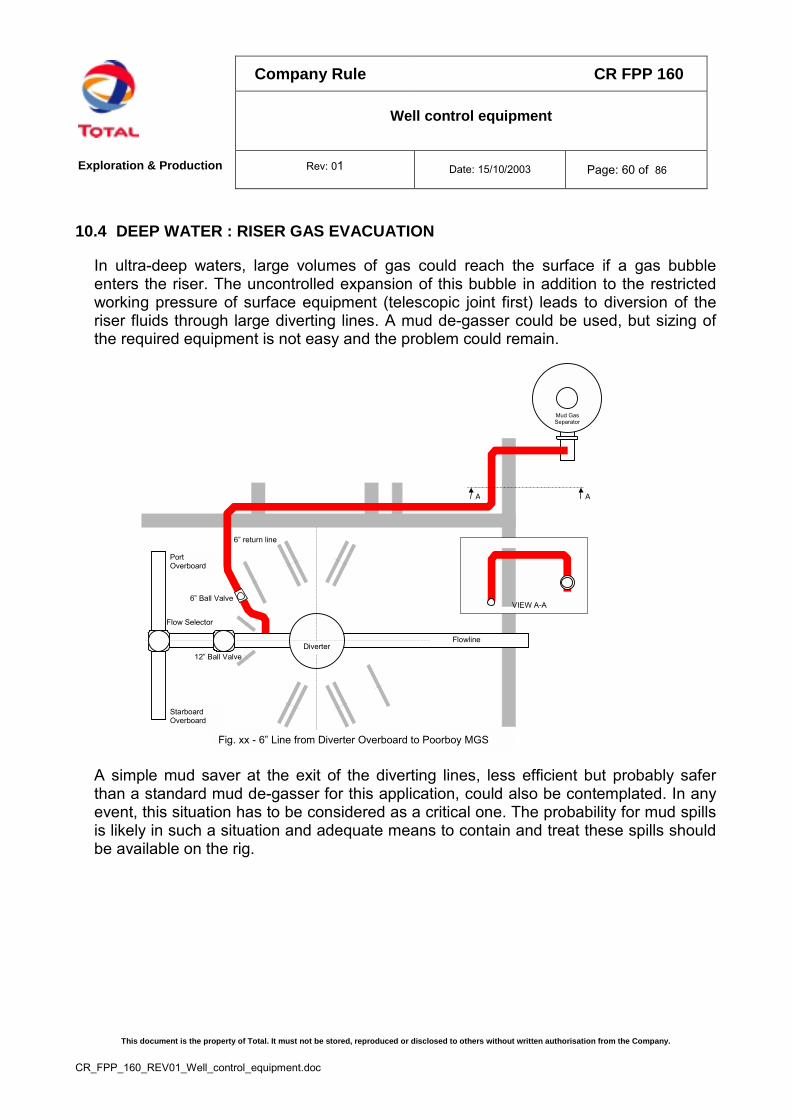
Company Rule CR FPP 160
Well control equipment
Exploration & Production Rev: 01 Date: 15/10/2003 Page: 60 of 86
This document is the property of Total. It must not be stored, reproduced or disclosed to others without written authorisation from the Company.
CR_FPP_160_REV01_Well_control_equipment.doc
10.4 DEEP WATER : RISER GAS EVACUATION
In ultra-deep waters, large volumes of gas could reach the surface if a gas bubbleenters the riser. The uncontrolled expansion of this bubble in addition to the restrictedworking pressure of surface equipment (telescopic joint first) leads to diversion of theriser fluids through large diverting lines. A mud de-gasser could be used, but sizing ofthe required equipment is not easy and the problem could remain.
A A
VIEW A-A
Diverter
Mud GasSeparator
Fig. xx - 6” Line from Diverter Overboard to Poorboy MGS
PortOverboard
StarboardOverboard
Flowline
12” Ball Valve
6” Ball Valve
6” return line
Flow Selector
A simple mud saver at the exit of the diverting lines, less efficient but probably saferthan a standard mud de-gasser for this application, could also be contemplated. In anyevent, this situation has to be considered as a critical one. The probability for mud spillsis likely in such a situation and adequate means to contain and treat these spills shouldbe available on the rig.
Company Rule CR FPP 160
Well control equipment
Exploration & Production Rev: 01 Date: 15/10/2003 Page: 61 of 86
This document is the property of Total. It must not be stored, reproduced or disclosed to others without written authorisation from the Company.
CR_FPP_160_REV01_Well_control_equipment.doc
11. WELL CONTROL EQUIPMENT INSPECTION / CERTIFICATION /MAINTENANCE
11.1 GENERAL
Rule 50: A Well Control Equipment log book is mandatory on each rig and will be partof the site Safety Register
It is the drilling and completion supervisor’s role to periodically verify that theWell Control Equipment log book is issued, available and up to date.
The rig Well Control Equipment log book is constituted with:� Certification package by the manufacturer or an approved third party with
API monogram. API manufacturing documentation, NACE certificationincluding raw material traceability. Manufacturers must provide fulltraceability of Well Control Equipment and spare parts.
� Commissioning Well Control Equipment inspection report and action plan� inspection reports and following action plans after periodic inspections of
Well Control Equipment� any inspection reports after repair or change of equipment.� repair / change log book. Dates, technical reason for change, part
number and working limitations of installed components (pressure,temperature rating, OBM compatibility, etc) shall be recorded andapproved by the rig manager.
� maintenance log book.
This log book ensures that the manufacturer's BOP operating manual is followed and noalterations/modifications have been made to the BOP equipment without writtenconsent from the manufacturer.
Spare Parts: Only original equipment manufacturer’s spares will be used for WellControl Equipment replacement parts.
In order to extend the life of the BOP seals and associated equipment (depending onthe type of mud, temperature and gas environment), particular attention will be given tothe choice of the sealing material. The manufacturer’s standards will be followed.
Storage conditions will follow the manufacturer recommendations. It will be rememberedthat rubber can be damaged by temperature, UV radiation and ozone created byelectrical motors.
Company Rule CR FPP 160
Well control equipment
Exploration & Production Rev: 01 Date: 15/10/2003 Page: 62 of 86
This document is the property of Total. It must not be stored, reproduced or disclosed to others without written authorisation from the Company.
CR_FPP_160_REV01_Well_control_equipment.doc
11.2 RIG ACCEPTANCE
The required BOP inspection program will be clearly highlighted in the call for tenderacceptance.
Rig acceptance will include a review of the Well Control Equipment certification packageand Well Control Equipment maintenance log book.
Rule 51: A new certification is required if, at the rig acceptance stage, the BOPdocuments file (previous certificates, log book, etc) is missing or badlycompleted.A complete BOP stack dismantling and inspection shall be carried out forcertification when control equipment has been stacked for a period equal toor greater than 6 monthsAt the rig acceptance stage, periodic inspections will be checked
At the rig acceptance stage, periodic inspections (refer to paragraph 11.3) will bechecked.
All ram cavities, the bag preventer and all gate valves will be opened and carefullychecked. All seals and gaskets will be replaced with new ones. The packer could alsobe changed if deemed necessary. On stacks equipped with hydraulic rams locks, ramslocks will to be stripped, checked and tested.
It is recommended to change the packing system(s) of annular preventer(s) at the rigacceptance stage if it has been in use for more than one year.
Coflexip type (or equivalent) hoses are recommended to be inspected internally
The external condition of all BOP control flexible hoses will be checked.
11.3 PERIODIC INSPECTIONS
Rule 52: A complete BOP stack dismantling and inspection shall be carried out forcertification if:� equipment is in continuous use for more than 5 years� equipment was subject to abnormal conditions (excessive shock, fire,
etc).
A clean out and visual inspection of bag preventer packer, rams, ram cavities, tightnessof flange and connectors and verification of pre-charge pressures in accumulators willbe carried out prior to each well.
Company Rule CR FPP 160
Well control equipment
Exploration & Production Rev: 01 Date: 15/10/2003 Page: 63 of 86
This document is the property of Total. It must not be stored, reproduced or disclosed to others without written authorisation from the Company.
CR_FPP_160_REV01_Well_control_equipment.doc
An internal inspection of Coflexip type (or equivalent) hoses is recommended once ayear. The external condition will be also checked.
A calibration of all pressure gauges is recommended once every 3 years.
11.4 MODIFICATIONS, CHANGES
Rule 53: A new certification is required in the case of repair inducing hot work
All modifications, design changes or weld repairs to Well Control Equipment will complywith appropriate API specifications or manufacturer specifications or local governmentregulations whichever is more stringent.
Company Rule CR FPP 160
Well control equipment
Exploration & Production Rev: 01 Date: 15/10/2003 Page: 64 of 86
This document is the property of Total. It must not be stored, reproduced or disclosed to others without written authorisation from the Company.
CR_FPP_160_REV01_Well_control_equipment.doc
APPENDIX
Appendix 1: Drawings
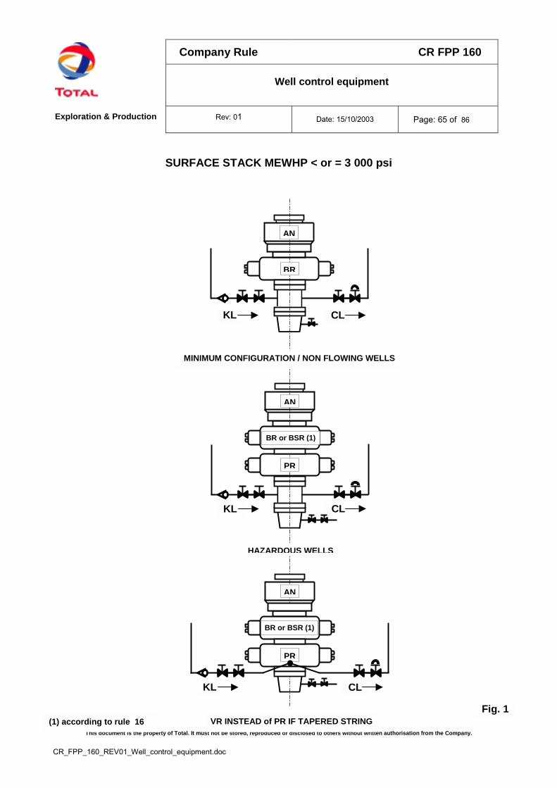
Company Rule CR FPP 160
Well control equipment
Exploration & Production Rev: 01 Date: 15/10/2003 Page: 65 of 86
property of Total. It must not be stored, reproduced or disclosed to others without written authorisation from the Company.
SURFACE STACK MEWHP < or = 3 000 psi
Fig. 1VR INSTEAD of PR IF TAPERED STRING
KL CL
KL CL
AN
PR
KL CL
MINIMUM CONFIGURATION / NON FLOWING WELLS
HAZARDOUS WELLS
AN
BR
AN
BR or BSR (1)
PR
BR or BSR (1)
This document is the
(1) according to rule 16
CR_FPP_160_REV01_Well_control_equipment.doc
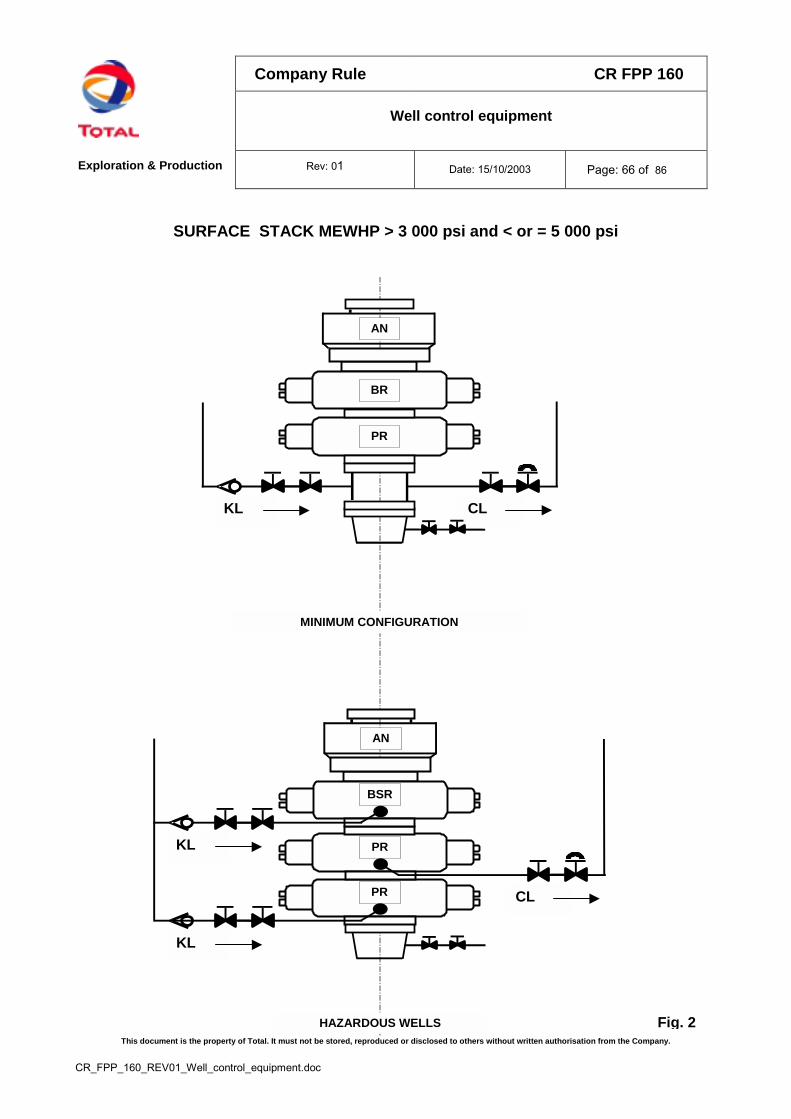
Company Rule CR FPP 160
Well control equipment
Exploration & Production Rev: 01 Date: 15/10/2003 Page: 66 of 86
This document is the property of Total. It must not be stored, reproduced or disclosed to others without written authorisation from the Company.
CR_FPP_160_REV01_Well_control_equipment.doc
SURFACE STACK MEWHP > 3 000 psi and < or = 5 000 psi
MINIMUM CONFIGURATION
KL CL
AN
BR
PR
CL
AN
PR
PR
BSR
KL
KL
HAZARDOUS WELLS Fig. 2
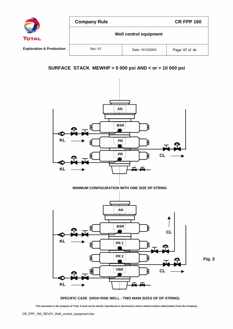
Company Rule CR FPP 160
Well control equipment
Exploration & Production Rev: 01 Date: 15/10/2003 Page: 67 of 86
This document is the property of Total. It must not be stored, reproduced or disclosed to others without written authorisation from the Company.
CR_FPP_160_REV01_Well_control_equipment.doc
SURFACE STACK MEWHP > 5 000 psi AND < or = 10 000 psi
Fig. 3
AN
BSR
KL
KL
CL
PR 2
VBR
PR 1
SPECIFIC CASE (HIGH RISK WELL - TWO MAIN SIZES OF DP STRING)
CL
CL
AN
PR
PR
BSR
KL
KL
MINIMUM CONFIGURATION WITH ONE SIZE DP STRING
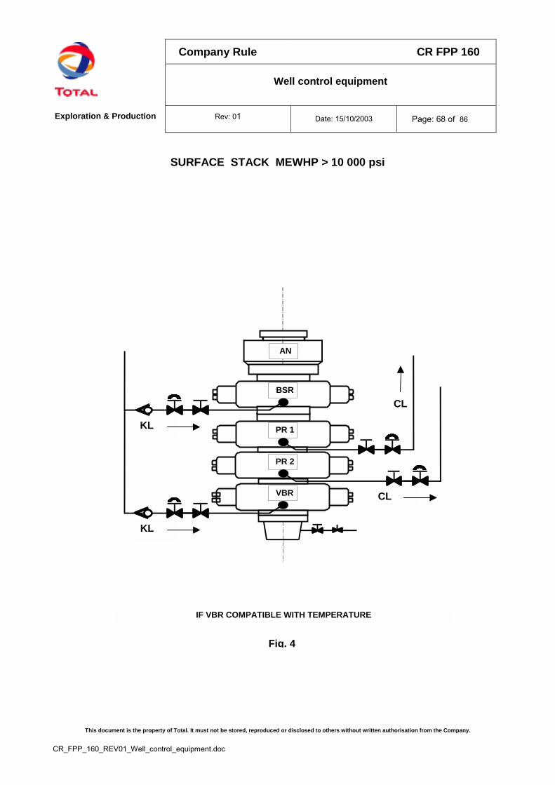
Company Rule CR FPP 160
Well control equipment
Exploration & Production Rev: 01 Date: 15/10/2003 Page: 68 of 86
This document is the property of Total. It must not be stored, reproduced or disclosed to others without written authorisation from the Company.
CR_FPP_160_REV01_Well_control_equipment.doc
SURFACE STACK MEWHP > 10 000 psi
Fig. 4
AN
BSR
KL
KL
CL
PR 2
VBR
PR 1
IF VBR COMPATIBLE WITH TEMPERATURE
CL
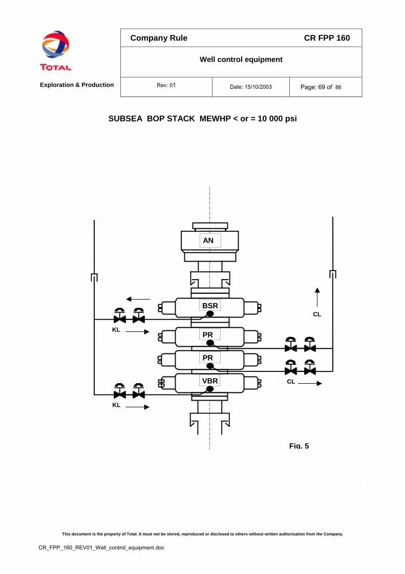
Company Rule CR FPP 160
Well control equipment
Exploration & Production Rev: 01 Date: 15/10/2003 Page: 69 of 86
This document is the property of Total. It must not be stored, reproduced or disclosed to others without written authorisation from the Company.
CR_FPP_160_REV01_Well_control_equipment.doc
SUBSEA BOP STACK MEWHP < or = 10 000 psi
Fig. 5
AN
BSR
KL
KL
CL
PR
VBR
PR
CL

Company Rule CR FPP 160
Well control equipment
Exploration & Production Rev: 01 Date: 15/10/2003 Page: 70 of 86
This document is the property of Total. It must not be stored, reproduced or disclosed to others without written authorisation from the Company.
CR_FPP_160_REV01_Well_control_equipment.doc
LARGE BORE SUBSEA BOP STACK MEWHP < or = 3 000 psi
Fig. 6
AN
BSR
KLPR
KL / CL

Company Rule CR FPP 160
Well control equipment
Exploration & Production Rev: 01 Date: 15/10/2003 Page: 71 of 86
This document is the property of Total. It must not be stored, reproduced or disclosed to others without written authorisation from the Company.
CR_FPP_160_REV01_Well_control_equipment.doc
SUBSEA STACK MEWHP > 10 000 psi
AN
BSR
KL
KL
CL
PR
VBR
PR
CL
AN
Fig. 7
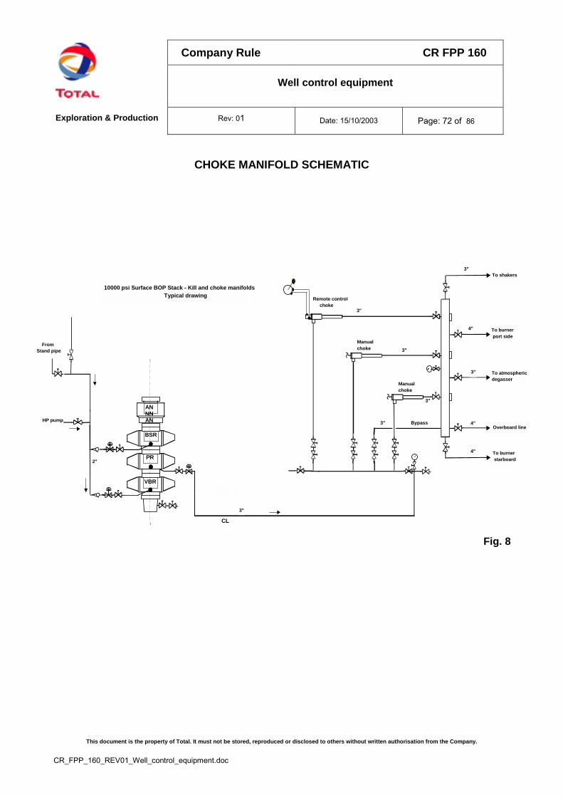
Company Rule CR FPP 160
Well control equipment
Exploration & Production Rev: 01 Date: 15/10/2003 Page: 72 of 86
This document is the property of Total. It must not be stored, reproduced or disclosed to others without written authorisation from the Company.
CR_FPP_160_REV01_Well_control_equipment.doc
CHOKE MANIFOLD SCHEMATIC
10000 psi Surface BOP Stack - Kill and choke manifolds Typical drawing
Fig. 8
4"
To burnerport side
To burnerstarboard
To atmosphericdegasser
To shakers
Overboard lineBypass
Remote control choke
3"
3"
3"
Manualchoke
Manualchoke
3"
3"
3"
4"
4"
ANNNAN
PR
BSR
VBR
HP pump
From Stand pipe
CL
2"
3"
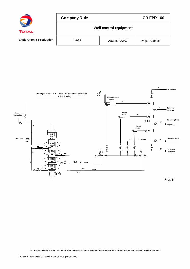
Company Rule CR FPP 160
Well control equipment
Exploration & Production Rev: 01 Date: 15/10/2003 Page: 73 of 86
This document is the property of Total. It must not be stored, reproduced or disclosed to others without written authorisation from the Company.
CR_FPP_160_REV01_Well_control_equipment.doc
To atmospheric
Overboard line
10000 psi Surface BOP Stack - Kill and choke manifolds Typical drawing
Fig. 9
4"
To burnerport side
To burnerstarboard
degasser
To shakers
Bypass
Remote control choke
3"
3"
3"
Manualchoke
Manualchoke
3"
3"
3"
4"
4"
ANNNAN
PR1
BSR
PR2
VBR
HP pump
From Stand pipe
CL2
2"
CL1
3"
3"
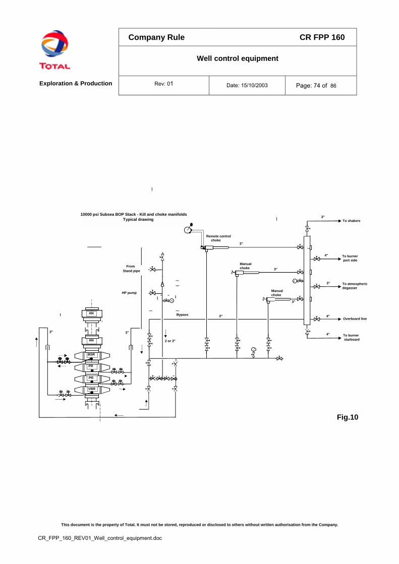
Company Rule CR FPP 160
Well control equipment
Exploration & Production Rev: 01 Date: 15/10/2003 Page: 74 of 86
This document is the property of Total. It must not be stored, reproduced or disclosed to others without written authorisation from the Company.
CR_FPP_160_REV01_Well_control_equipment.doc
4"
To burnerport side
To burnerstarboard
To atmosphericdegasser
To shakers
Overboard lineBypass
Remote control choke
10000 psi Subsea BOP Stack - Kill and choke manifolds Typical drawing
Fig.10
AN
PR
PR
BSR
VBR
AN
2 or 3"
3" 3"
HP pump
FromStand pipe
3"
3"
3"
Manualchoke
Manualchoke
3"
3"
3"
4"
4"

Company Rule CR FPP 160
Well control equipment
Exploration & Production Rev: 01 Date: 15/10/2003 Page: 75 of 86
This document is the property of Total. It must not be stored, reproduced or disclosed to others without written authorisation from the Company.
CR_FPP_160_REV01_Well_control_equipment.doc
HYDRAULIC CONTROL UNIT SCHEMATIC
to annular preventer
to rams & valves
By Pass Valve
Pumpsystem 1
Pumpsystem 2
By Pass Valve
Accumulators Set 1 Accumulators Set 2
Fig. 11
to another pump
Basic Surface BOP Control System
Regulator Valve
Regulator Valve
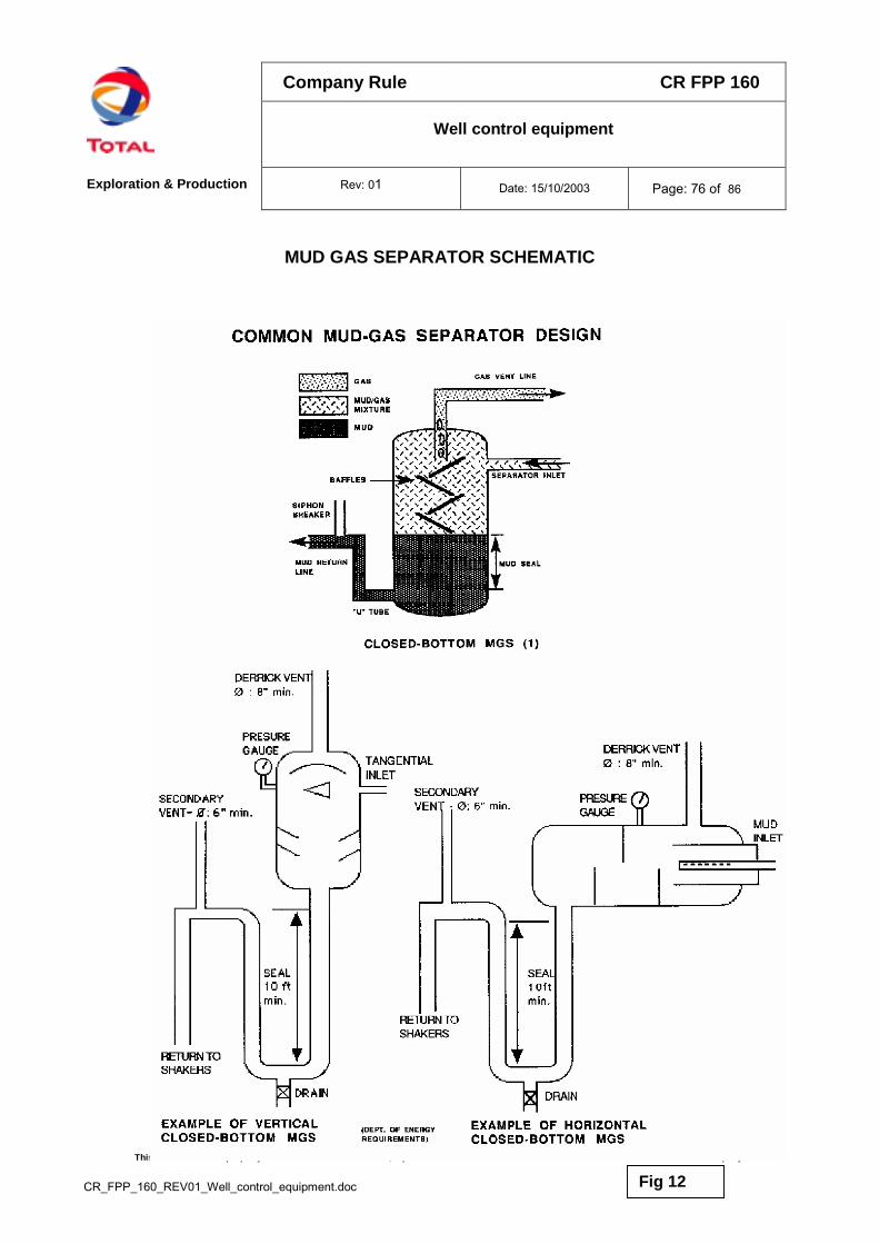
Company Rule CR FPP 160
Well control equipment
Exploration & Production Rev: 01 Date: 15/10/2003 Page: 76 of 86
This document is the property of Total. It must not be stored, reproduced or disclosed to others without written authorisation from the Company.
CR_FPP_160_REV01_Well_control_equipment.doc
MUD GAS SEPARATOR SCHEMATIC
Fig. 10Fig 12
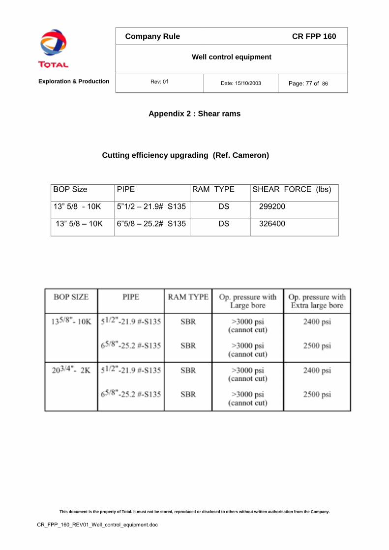
Company Rule CR FPP 160
Well control equipment
Exploration & Production Rev: 01 Date: 15/10/2003 Page: 77 of 86
This document is the property of Total. It must not be stored, reproduced or disclosed to others without written authorisation from the Company.
CR_FPP_160_REV01_Well_control_equipment.doc
Appendix 2 : Shear rams
Cutting efficiency upgrading (Ref. Cameron)
BOP Size PIPE RAM TYPE SHEAR FORCE (lbs)
13” 5/8 - 10K 5”1/2 – 21.9# S135 DS 299200
13” 5/8 – 10K 6”5/8 – 25.2# S135 DS 326400
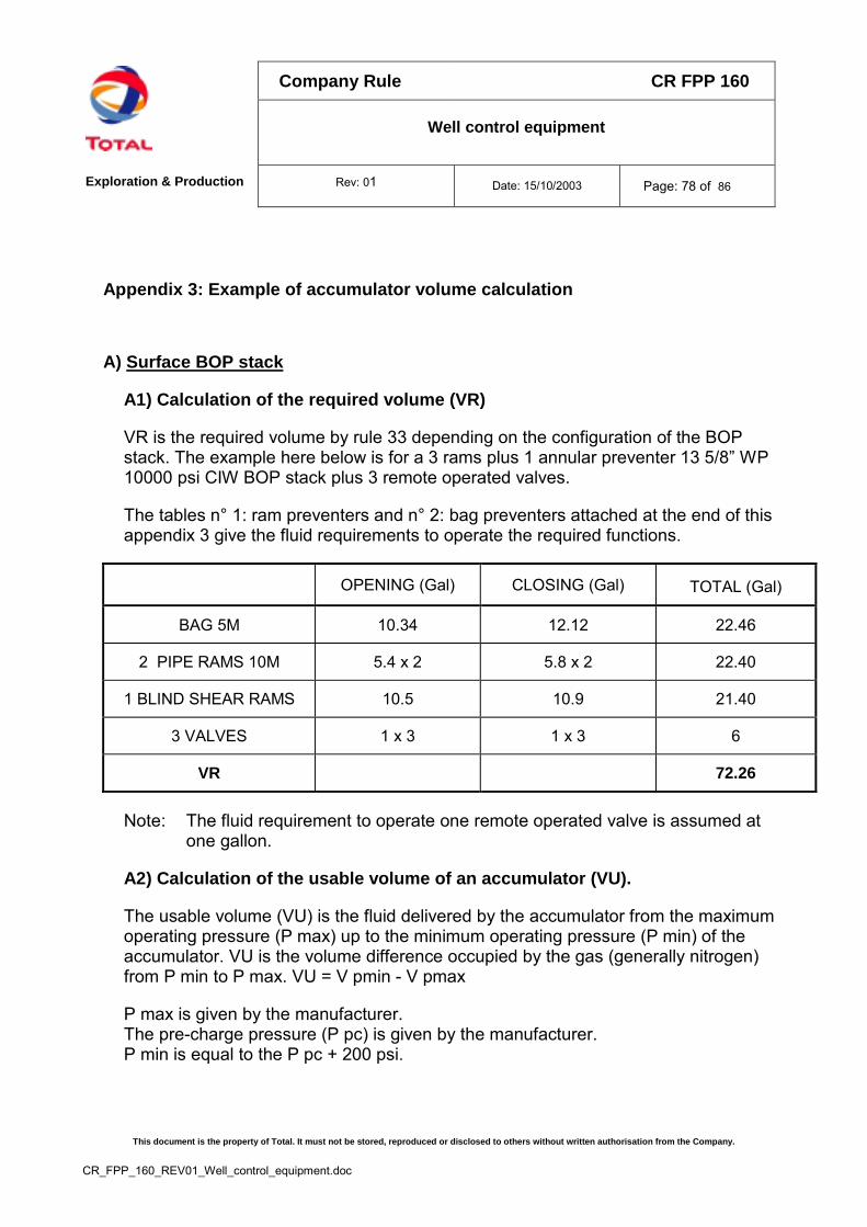
Company Rule CR FPP 160
Well control equipment
Exploration & Production Rev: 01 Date: 15/10/2003 Page: 78 of 86
This document is the property of Total. It must not be stored, reproduced or disclosed to others without written authorisation from the Company.
CR_FPP_160_REV01_Well_control_equipment.doc
Appendix 3: Example of accumulator volume calculation
A) Surface BOP stack
A1) Calculation of the required volume (VR)
VR is the required volume by rule 33 depending on the configuration of the BOPstack. The example here below is for a 3 rams plus 1 annular preventer 13 5/8” WP10000 psi CIW BOP stack plus 3 remote operated valves.
The tables n° 1: ram preventers and n° 2: bag preventers attached at the end of thisappendix 3 give the fluid requirements to operate the required functions.
OPENING (Gal) CLOSING (Gal) TOTAL (Gal)
BAG 5M 10.34 12.12 22.46
2 PIPE RAMS 10M 5.4 x 2 5.8 x 2 22.40
1 BLIND SHEAR RAMS 10.5 10.9 21.40
3 VALVES 1 x 3 1 x 3 6
VR 72.26
Note: The fluid requirement to operate one remote operated valve is assumed atone gallon.
A2) Calculation of the usable volume of an accumulator (VU).
The usable volume (VU) is the fluid delivered by the accumulator from the maximumoperating pressure (P max) up to the minimum operating pressure (P min) of theaccumulator. VU is the volume difference occupied by the gas (generally nitrogen)from P min to P max. VU = V pmin - V pmax
P max is given by the manufacturer.The pre-charge pressure (P pc) is given by the manufacturer.P min is equal to the P pc + 200 psi.
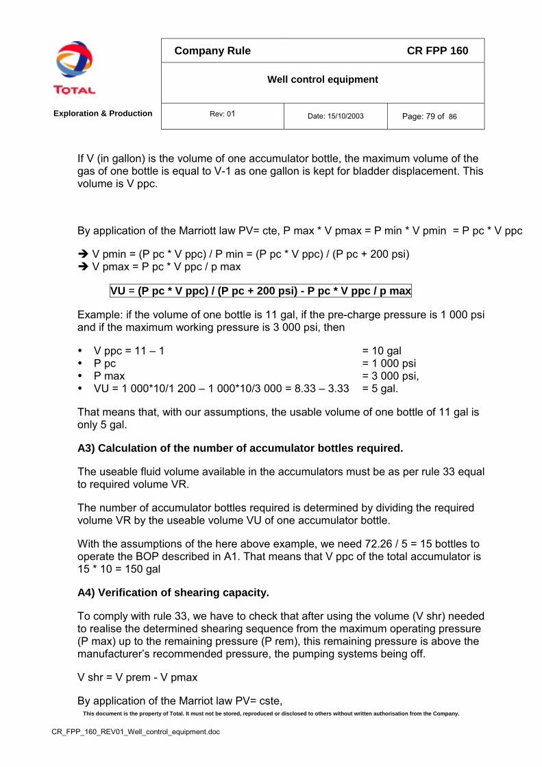
Company Rule CR FPP 160
Well control equipment
Exploration & Production Rev: 01 Date: 15/10/2003 Page: 79 of 86
This document is the property of Total. It must not be stored, reproduced or disclosed to others without written authorisation from the Company.
CR_FPP_160_REV01_Well_control_equipment.doc
If V (in gallon) is the volume of one accumulator bottle, the maximum volume of thegas of one bottle is equal to V-1 as one gallon is kept for bladder displacement. Thisvolume is V ppc.
By application of the Marriott law PV= cte, P max * V pmax = P min * V pmin = P pc * V ppc
� V pmin = (P pc * V ppc) / P min = (P pc * V ppc) / (P pc + 200 psi)� V pmax = P pc * V ppc / p max
VU = (P pc * V ppc) / (P pc + 200 psi) - P pc * V ppc / p max
Example: if the volume of one bottle is 11 gal, if the pre-charge pressure is 1 000 psiand if the maximum working pressure is 3 000 psi, then
� V ppc = 11 – 1 = 10 gal� P pc = 1 000 psi� P max = 3 000 psi,� VU = 1 000*10/1 200 – 1 000*10/3 000 = 8.33 – 3.33 = 5 gal.
That means that, with our assumptions, the usable volume of one bottle of 11 gal isonly 5 gal.
A3) Calculation of the number of accumulator bottles required.
The useable fluid volume available in the accumulators must be as per rule 33 equalto required volume VR.
The number of accumulator bottles required is determined by dividing the requiredvolume VR by the useable volume VU of one accumulator bottle.
With the assumptions of the here above example, we need 72.26 / 5 = 15 bottles tooperate the BOP described in A1. That means that V ppc of the total accumulator is15 * 10 = 150 gal
A4) Verification of shearing capacity.
To comply with rule 33, we have to check that after using the volume (V shr) neededto realise the determined shearing sequence from the maximum operating pressure(P max) up to the remaining pressure (P rem), this remaining pressure is above themanufacturer’s recommended pressure, the pumping systems being off.
V shr = V prem - V pmax
By application of the Marriot law PV= cste,

Company Rule CR FPP 160
Well control equipment
Exploration & Production Rev: 01 Date: 15/10/2003 Page: 80 of 86
This document is the property of Total. It must not be stored, reproduced or disclosed to others without written authorisation from the Company.
CR_FPP_160_REV01_Well_control_equipment.doc
P max * V pmax = P rem * V prem � P rem = ( P max * V pmax ) / V prem
with V pmax = P pc * V ppc / P max
P rem = (P pc * V ppc) / ( V shr + V pmax )
With the assumptions of the here above example and with the BOP described in A1:
� V shr = 5.8 (VR for the set of PR) + 10.9 (VR for the shear) = 16.7 gal� V p max = 1 000 *150 / 3 000 = 50 gal� P rem = (1 000* 150 ) / ( 16.7 + 50 ) = 2 249 psi
As P rem is above the manufacturer’s recommended pressure at the end of theshearing process (usually around 2000 psi), the size of this accumulator is correct.
However the manufacturer’s recommended pressure at the end of the shearingprocess could be more than 2 000 psi for specific cases (5 ½” drill pipes or no largebore shear bonnets and/or no tandem boosters installed).
B) Subsea BOP stack
B1) Calculation of the required volume VR.
VR is the required volume by rule 34 depending on the configuration of the BOPstack. The example here below is for a 3 pipe rams plus 1 shear pipe rams plus 1annular preventer 18 3/4” WP 10 000 psi CIW type U BOP stack plus 8 remoteoperated valves.
The tables n° 1: ram preventers and n° 2: bag preventers attached to this appendix 3give the fluid requirements to operate the required functions
OPENING (Gal) CLOSING (Gal) TOTAL (Gal)BAG 10M 45.1 51.0 96.1
3 PIPE RAMS 10M 21.2 x 3 23.1 x 3 132.91 BLIND SHEAR RAMS 21.2 23.1 44.3
8 VALVES 1 x 8 1 x 8 16TOTAL Functions
VR = 1.5 Total Functions289.3434
Company Rule CR FPP 160
Well control equipment
Exploration & Production Rev: 01 Date: 15/10/2003 Page: 81 of 86
This document is the property of Total. It must not be stored, reproduced or disclosed to others without written authorisation from the Company.
CR_FPP_160_REV01_Well_control_equipment.doc
Note: The fluid requirement to operate one remote operated valve is assumed atone gallon.
B2) Calculation of the usable volume of an accumulator VU.
For the part of the surface accumulator bottles, the calculation of VU of this surfacepart (VU surf) is done as described in A2.The calculation of the usable volume of the subsea part of accumulator (VU ss) isdifferent as the pre-charge and the maximum operating pressure of the subseaaccumulator bottles should be increased to compensate for:
� the hydrostatic head of the sea water column� the compressibility and temperature effect on the pre-charge gas behaviour
should also be taken into consideration when calculating the usable volume ofthe subsea accumulators.
a) the hydrostatic head of the sea water column
The following technique can be used to size accumulator bottles for subseaoperation, assuming a ML water depth.The hydrostatic pressure at ML (P ml) is 1.03*0.981*ML (m)/10 in bars or 14.5xP ml in psi.
The pre-charge pressure (P pcss) has to be increased to compensate for thehydrostatic head of the sea water column. Therefore, P pcss for subsea accumulatoris the P pc at surface conditions (given by manufacturer) plus the hydrostaticpressure P ml.P pcss = P pc + P mlP minss = P pcss + 200 psi = P pc + P ml + 200 psi
For the maximum operating pressure at bottom conditions ( Pmaxss ) samecorrection has to be made:P maxss = P max + P ml
b) the compressibility and temperature effect on the gas behaviour
The compressibility factor Z of a gas is a function of the temperature and thepressure. This compressibility factor Z is used in the gas law: P * V / T *Z = constant(T in ° Kelvin)
Company Rule CR FPP 160
Well control equipment
Exploration & Production Rev: 01 Date: 15/10/2003 Page: 82 of 86
This document is the property of Total. It must not be stored, reproduced or disclosed to others without written authorisation from the Company.
CR_FPP_160_REV01_Well_control_equipment.doc
With:� T surf = surface temperature in ° C plus 273.� T bot = sea bottom temperature in ° C plus 273� Z pc = the compressibility factor of the gas in the accumulator bottle at surface
temperature T surf and at a pressure of P pcss.� Z pmin = the compressibility factor of the gas in the accumulator bottle at sea
bottom temperature T bot and at a pressure of P minss.� Z pmax = the compressibility factor of the gas in the accumulator bottle at sea
bottom temperature T bot and at a pressure of P maxss.
COMPRESSIBILITY FACTOR OF NITROGEN (From Sage&Lacy API project N°37)figure n° 1
The usable volume of a subsea accumulator (VU ss) is the fluid delivered by theaccumulator from the maximum operating pressure (P maxss) up to the minimumoperating pressure (P minss) of the accumulator. VU ss is the volume differenceoccupied by the gas (generally nitrogen) from P minss to P maxss.VU ss= V pminss - V pmaxss
Nitrogen compressibility factor
0,9
1
1,1
1,2
1,3
1,4
1,5
2000 4000 6000 8000 10000 12000
Pressure in psi
Z co
mpr
essi
bilit
y fa
ctor
Z at 4°CZ at 30°C
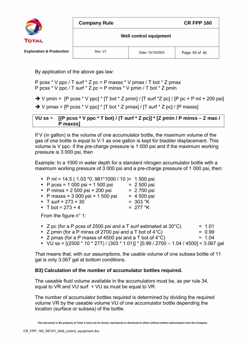
Company Rule CR FPP 160
Well control equipment
Exploration & Production Rev: 01 Date: 15/10/2003 Page: 83 of 86
This document is the property of Total. It must not be stored, reproduced or disclosed to others without written authorisation from the Company.
CR_FPP_160_REV01_Well_control_equipment.doc
By application of the above gas law:
P pcss * V ppc / T surf * Z pc = P maxss * V pmax / T bot * Z pmaxP pcss * V ppc / T surf * Z pc = P minss * V pmin / T bot * Z pmin
� V pmin = [P pcss * V ppc] * [T bot * Z pmin] / [T surf *Z pc] / [P pc + P ml + 200 psi]� V pmax = [P pcss * V ppc] * [T bot * Z pmax] / [T surf * Z pc] / [P maxss]
VU ss = [(P pcss * V ppc * T bot) / (T surf * Z pc)] * [Z pmin / P minss – Z max /P maxss]
If V (in gallon) is the volume of one accumulator bottle, the maximum volume of thegas of one bottle is equal to V-1 as one gallon is kept for bladder displacement. Thisvolume is V ppc. if the pre-charge pressure is 1 000 psi and if the maximum workingpressure is 3 000 psi, then
Example: In a 1000 m water depth for a standard nitrogen accumulator bottle with amaximum working pressure of 3 000 psi and a pre-charge pressure of 1 000 psi, then:
� P ml = 14.5 ( 1.03 *0. 981*1000 / 10 )= 1 500 psi� P pcss = 1 000 psi + 1 500 psi = 2 500 psi� P minss = 2 500 psi + 200 psi = 2 700 psi� P maxss = 3 000 psi + 1 500 psi = 4 500 psi� T surf = 273 + 30 = 303 °K� T bot = 273 + 4 = 277 °KFrom the figure n° 1:
� Z pc (for a P pcss of 2500 psi and a T surf estimated at 30°C) = 1.01� Z pmin (for a P minss of 2700 psi and a T bot of 4°C) = 0.99� Z pmax (for a P maxss of 4500 psi and a T bot of 4°C) = 1.04� VU ss = [(2500 * 10 * 277) / (303 * 1.01)] * [0.99 / 2700 – 1.04 / 4500] = 3.067 gal
That means that, with our assumptions, the usable volume of one subsea bottle of 11gal is only 3.067 gal at bottom conditions.
B3) Calculation of the number of accumulator bottles required.
The useable fluid volume available in the accumulators must be, as per rule 34,equal to VR and VU surf + VU ss must be equal to VR
The number of accumulator bottles required is determined by dividing the requiredvolume VR by the useable volume VU of one accumulator bottle depending thelocation (surface or subsea) of the bottle.
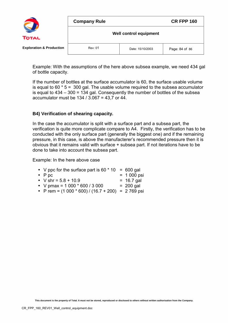
Company Rule CR FPP 160
Well control equipment
Exploration & Production Rev: 01 Date: 15/10/2003 Page: 84 of 86
This document is the property of Total. It must not be stored, reproduced or disclosed to others without written authorisation from the Company.
CR_FPP_160_REV01_Well_control_equipment.doc
Example: With the assumptions of the here above subsea example, we need 434 galof bottle capacity.
If the number of bottles at the surface accumulator is 60, the surface usable volumeis equal to 60 * 5 = 300 gal. The usable volume required to the subsea accumulatoris equal to 434 – 300 = 134 gal. Consequently the number of bottles of the subseaaccumulator must be 134 / 3.067 = 43,7 or 44.
B4) Verification of shearing capacity.
In the case the accumulator is split with a surface part and a subsea part, theverification is quite more complicate compare to A4. Firstly, the verification has to beconducted with the only surface part (generally the biggest one) and if the remainingpressure, in this case, is above the manufacterer’s recommended pressure then it isobvious that it remains valid with surface + subsea part. If not iterations have to bedone to take into account the subsea part.
Example: In the here above case
� V ppc for the surface part is 60 * 10 = 600 gal� P pc = 1 000 psi� V shr = 5.8 + 10.9 = 16.7 gal� V pmax = 1 000 * 600 / 3 000 = 200 gal� P rem = (1 000 * 600) / (16.7 + 200) = 2 769 psi
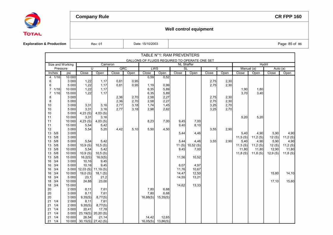
Company Rule CR FPP 160
Well control equipment
Exploration & Production Rev: 01 Date: 15/10/2003 Page: 85 of 86
Inches psi Close Open Close Open Close Open Close Open Close Open Close Open Close Open4 1/16 10 000 0,59 0,526 3 000 1,22 1,17 0,81 0,95 2,75 2,306 5 000 1,22 1,17 0,81 0,95 1,19 0,99 2,75 2,307 1/16 10 000 1,22 1,17 6,35 5,89 1,90 1,807 1/16 15 000 1,22 1,17 6,35 5,89 3,70 3,408 3 000 2,36 2,70 2,58 2,27 2,75 2,308 5 000 2,36 2,70 2,58 2,27 2,75 2,30
10 3 000 3,31 3,16 2,77 3,18 1,74 1,45 3,25 2,7010 5 000 3,31 3,16 2,77 3,18 2,98 2,62 3,25 2,7010 5 000 4,23 (S) 4,03 (S)11 10 000 3,31 3,16 5,20 5,2011 10 000 4,23 (S) 4,03 (S) 8,23 7,00 9,45 7,0011 15 000 5,54 5,42 9,40 8,1012 3 000 5,54 5,20 4,42 5,10 5,50 4,50 3,55 2,9013 5/8 3 000 5,44 4,46 5,40 4,90 5,90 4,9013 5/8 3 000 11,5 (S) 11,2 (S) 12 (S) 11,2 (S)13 5/8 5 000 5,54 5,42 5,44 4,46 3,55 2,90 5,40 4,90 5,90 4,9013 5/8 5 000 10,9 (S) 10,5 (S) 11 (S) 10,52 (S) 11,5 (S) 11,2 (S) 12 (S) 11,2 (S)13 5/8 10 000 5,54 5,42 9,45 7,00 11,80 11,80 12,90 11,8013 5/8 10 000 10,9 (S) 10,5 (S) 11,8 (S) 11,8 (S) 12,9 (S) 11,8 (S)13 5/8 15 000 16,2(S) 16,0(S) 11,56 10,5216 3/4 3 000 10,16 9,4516 3/4 5 000 10,16 9,45 6,07 4,9716 3/4 5 000 12,03 (S) 11,19 (S) 11,76 10,6716 3/4 10 000 19,0 (S) 18,1 (S) 14,47 12,50 15,80 14,1018 3/4 5 000 23,1 21,2 14,55 13,2118 3/4 10 000 24,88 23,00 17,10 15,6018 3/4 15 000 14,62 13,3320 2 000 8,11 7,61 7,80 6,6820 3 000 8,11 7,61 7,80 6,6820 3 000 9,35(S) 8,77(S) 16,88(S) 15,35(S)21 1/4 2 000 8,11 7,6121 1/4 2 000 9,35(S) 8,77(S)21 1/4 5 000 20,41 17,7821 1/4 5 000 23,19(S) 20,20 (S)21 1/4 10 000 26,54 21,14 14,42 12,6521 1/4 10 000 30,15(S) 27,42 (S) 16,05(S) 13,86(S)
TABLE N°1: RAM PREVENTERS GALLONS OF FLUIDS REQUIRED TO OPERATE ONE SET
Size and Working Pressure QRC Manual (a) Auto (a)
HydrilCameronLWS SL EU
NL Shaffer
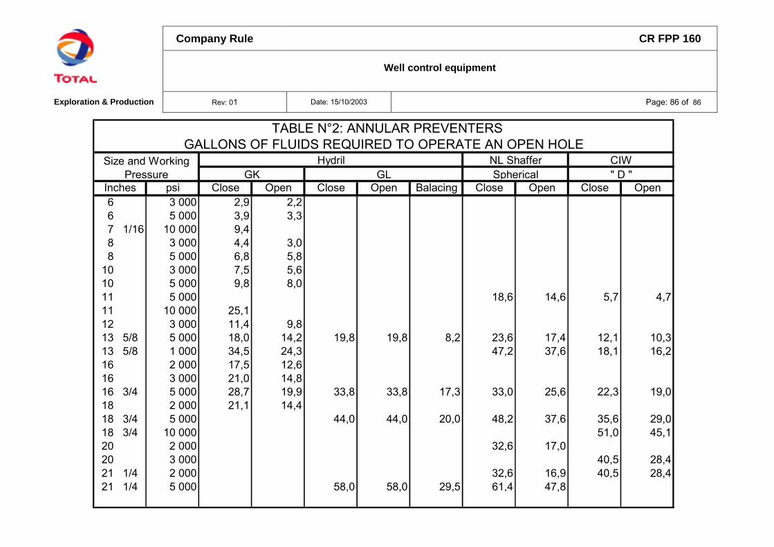
Company Rule CR FPP 160
Well control equipment
Exploration & Production Rev: 01 Date: 15/10/2003 Page: 86 of 86
Inches psi Close Open Close Open Balacing Close Open Close Open6 3 000 2,9 2,26 5 000 3,9 3,37 1/16 10 000 9,48 3 000 4,4 3,08 5 000 6,8 5,8
10 3 000 7,5 5,610 5 000 9,8 8,011 5 000 18,6 14,6 5,7 4,711 10 000 25,112 3 000 11,4 9,813 5/8 5 000 18,0 14,2 19,8 19,8 8,2 23,6 17,4 12,1 10,313 5/8 1 000 34,5 24,3 47,2 37,6 18,1 16,216 2 000 17,5 12,616 3 000 21,0 14,816 3/4 5 000 28,7 19,9 33,8 33,8 17,3 33,0 25,6 22,3 19,018 2 000 21,1 14,418 3/4 5 000 44,0 44,0 20,0 48,2 37,6 35,6 29,018 3/4 10 000 51,0 45,120 2 000 32,6 17,020 3 000 40,5 28,421 1/4 2 000 32,6 16,9 40,5 28,421 1/4 5 000 58,0 58,0 29,5 61,4 47,8
TABLE N°2: ANNULAR PREVENTERS GALLONS OF FLUIDS REQUIRED TO OPERATE AN OPEN HOLE
CIW" D "GK GL Spherical
Size and Working Pressure
Hydril NL Shaffer