cpw antenna_kesava reddy
TRANSCRIPT

7/30/2019 CPW Antenna_Kesava Reddy
http://slidepdf.com/reader/full/cpw-antennakesava-reddy 1/31
Rajiv Gan
Antenna
Freque
Kesava
U
Lectur
hi University of kno
Technologies
Design for Micr
cy Band Applic
By
eddy Jangam (ID: N6110
der the Guidance of
Mr. Riyaz hussain
r in the Department of E
RGU-IIIT, Nuzvid
Page | 1
ledge
Wave
tions
005)
E

7/30/2019 CPW Antenna_Kesava Reddy
http://slidepdf.com/reader/full/cpw-antennakesava-reddy 2/31
Page | 2
Table of ContentAbstract .................................................................................................................................................. 3
I. Introduction ........................ ...................... ............................ ................... ............................ ........... 4
II. Micro Wave Frequency Bands and Applications ..................... .............................. .................... ........ 5
II.a Electro Magnetic wave ....................... ......................... ............................ ................... .............. 5
II.b Electro Magnetic Wave Spectrum........................................................................................ 6
II.c Applications for the Micro Wave Spectrum ......................................................................... 7
II.d Ultra Wide Band .................................................................................................................... 7
II.e UWB History .......................................................................................................................... 8
II.f Advantages of UWB .............................................................................................................. 9
II.g UWB Standards................................................................................................................... 10
II.h UWB Applications................................................................................................................ 10
III. Antenna Theory .......................... ...................... ............................... ................... ....................... 12
III.a. Definition of Antenna ............................................................................................................. 12
III.b. Important Parameters of Antenna ......................................................................................... 13
III.c. Antenna Classification ............................................................................................................ 15
III.d. Requirements for UWB Antenna........................................................................................ 21
IV. Numerical Methods ............................ ......................... ........................... .......................... ......... 23
V. Antenna Design and Results ...................... .......................... ......................... ............................ ...... 24
V.a. Antenna Design ...................................................................................................................... 24
V.b. Simulated Results Analysis ..................................................................................................... 25
V.c. Conclusion ............................................................................................................................. 29
VI. Future Work and Conclusion ..................... ............................ ...................... ......................... ...... 30
V.a. Conclusion ............................................................................................................................. 30
V.b. Future Work ........................................................................................................................... 30
References ............................................................................................................................................ 31

7/30/2019 CPW Antenna_Kesava Reddy
http://slidepdf.com/reader/full/cpw-antennakesava-reddy 3/31
Page | 3
Abstract
This survey paper focuses on microwave frequency band antennas design and analysis.Studies have been undertaken covering the areas of microwave frequency band fundamentalsand antenna theory. In microwave frequency bands Ultra wide band (UWB) is one of the mostimportant bands.
Ultra wide band is rapidly advancing as a high data rate wireless communication technology. Asis the case in conventional wireless communication systems, an antenna also plays a verycrucial role in UWB systems. However, there are more challenges in designing a UWB antennathan a narrow band one. A suitable UWB antenna should be capable of operating over an ultrawide bandwidth as allocated by the FCC. At the same time, satisfactory radiation propertiesover the entire frequency range are also necessary. Another primary requirement of the UWBantenna is a good time domain performance, i.e. a good impulse response with minimaldistortion.
For this we are design an antenna and the simulation results of this antenna are analyzed byusing Method of Moment (MOM) based IE3D software. And also analyze the antennaparameters like return loss, radiation pattern, gain, directivity, efficiency and VSWR etc.

7/30/2019 CPW Antenna_Kesava Reddy
http://slidepdf.com/reader/full/cpw-antennakesava-reddy 4/31
Page | 4
I. Introduction
Wireless communication technology has changed our lives during the past twodecades. In countless homes and offices, the cordless phones free us from the shortleash of handset cords. Cell phones give us even more freedom such that we cancommunicate with each other at any time and in any place. Wireless local area network(WLAN) technology provides us access to the internet without suffering from managingyards of unsightly and expensive cable.
The technical improvements have also enabled a large number of new services toemerge. The first-generation (1G) mobile communication technology only allowedanalogue voice communication while the second-generation (2G) technology realizeddigital voice communication. Currently, the third-generation (3G) technology can provide
video telephony, internet access, video/music download services as well as digital voiceservices. In the near future, the fourth-generation (4G) technology will be able to provideon-demand high quality audio and video services, and other advanced services.
In recent years, more interests have been put into wireless personal area network(WPAN) technology worldwide. The future WPAN aims to provide reliable wirelessconnections between computers, portable devices and consumer electronics within ashort range. Furthermore, fast data storage and exchange between these devices willalso be accomplished. This requires a data rate which is much higher than what can beachieved through currently existing wireless technologies.
The maximum achievable data rate or capacity for the ideal band-limited additive whiteGaussian noise (AWGN) channel is related to the bandwidth and signal-to-noise ratio(SNR) by Shannon-Nyquist criterion, as shown in Equation.
C = B log2 (1 + SNR )
Where C denotes the maximum transmit data rate, B stands for the channel bandwidth.
Equation indicates that the transmit data rate can be increased by increasing thebandwidth occupation or transmission power. However, the transmission power cannotbe readily increased because many portable devices are battery powered and thepotential interference should also be avoided. Thus, a large frequency bandwidth will bethe solution to achieve high data rate.
On February 14, 2002, the Federal Communications Commission (FCC) of the UnitedStates adopted the First Report and Order that permitted the commercial operation ofultra wideband (UWB) technology [3]. Since then, UWB technology has been regardedas one of the most promising wireless technologies that promises to revolutionize highdata rate transmission and enables the personal area networking industry leading tonew innovations and greater quality of services to the end users.

7/30/2019 CPW Antenna_Kesava Reddy
http://slidepdf.com/reader/full/cpw-antennakesava-reddy 5/31
Page | 5
II. Micro Wave Frequency Bands and
ApplicationsII.a Electro Magnetic wave
Electromagnetic waves are disturbances to the electrical and magnetic fields. Achanging electric disturbance produces a changing magnetic field at right angle to theelectric field.
Electromagnetic Wave originates from a point in free space, spreads out uniformly in alldirections and it forms a spherical wave. At a large distance from the source the wavehas similar properties to the plane waves in the strip line and so by analogy of strip linesthe properties of EM waves in free space as follows:
Figure: Propagation of Electromagnetic wave
1. At every point in space, the electric vector field E and the magnetic vector field H areperpendicular to each other and to the direction of propagation as shown in the abovefigure.
2. Velocity of EM wave in free space is given by c= 3 × 10^8 m/s
3. E and H oscillate in phase and ratio of their amplitude is constant being equal to120pi or 377Ohm
4. Whatever may be the frequency, the EM waves travels in space with the velocity oflight.
5. EM wave propagates in free space as Transverse Electro Magnetic waves (TEMmode).

7/30/2019 CPW Antenna_Kesava Reddy
http://slidepdf.com/reader/full/cpw-antennakesava-reddy 6/31
Page | 6
Equation of EM waves in free space is given by:
II.b Electro Magnetic Wave Spectrum
As antennas dimensions are dependent on wavelength of the signal being transmitted,one should to know about the electromagnetic spectrum to know frequencies andwavelength of EM wave in different regions.

7/30/2019 CPW Antenna_Kesava Reddy
http://slidepdf.com/reader/full/cpw-antennakesava-reddy 7/31
II.c Applications for the
• CommunicationTerrestrialSatellite
•RadarSurveillanceTrackingGuidanceRange instrumentatiWeather, scientific
• NavigationEnrooted position s
Landing systems• Electronic WarfareIntelligence gatherinCountermeasures
• OtherMW ovens and induParticle acceleratorsRadio astronomyTelemetryAntenna test ranges
II.d Ultra Wide Band
UWB technology has bcommunications during thoccurred since February 2for data communicationswireless communication te
This section presents afundamentals, includingstandard activities.
Micro Wave Spectrum
on
stems
g
trial heating
en used in the areas of radar, spast 20 years. A Substantial surge of r02, when the FCC issued a ruling that
as well as for radar and safety applihnology for various amplifications.
brief overview of UWB technologWB definition, advantages, current r
Page | 7
nsing and militaryesearch interest hasUWB could be usedations. Since then,
and explores itsgulation state and

7/30/2019 CPW Antenna_Kesava Reddy
http://slidepdf.com/reader/full/cpw-antennakesava-reddy 8/31
Page | 8
UWB systems have been historically based on impulse radio because it transmitteddata at very high data rates by sending pulses of energy rather than using a narrow-band frequency carrier. Normally, the pulses have very short durations, typically a fewnanoseconds (billionths of a second) that results in an ultra wideband frequencyspectrum.
II.e UWB History
The concept of impulse radio initially originated with Marconi, in the 1900s, when sparkgap transmitters induced pulsed signals having very wide bandwidths. At that time,there was no way to effectively recover the wideband energy emitted by a spark gaptransmitter or discriminate among many such wideband signals in a receiver. As aresult, wideband signals caused too much interference with one another. So thecommunications world abandoned wideband communication in favor of narrowband
radio transmitter that was easy to regulate and coordinate.
In 1942-1945, several patents were filed on impulse radio systems to reduceinterference and enhance reliability. However, many of them were frozen for a long timebecause of the concerns about its potential military usage by the U.S. government. It isin the 1960s that impulse radio technologies started being developed for radar andmilitary applications.
In the mid 1980s, the FCC allocated the Industrial Scientific and Medicine (ISM) bandsfor unlicensed wideband communication use. Owing to this revolutionary spectrumallocation, WLAN and Wireless Fidelity (Wi-Fi) have gone through a tremendous
growth. It also leads the communication industry to study the merits and implications ofwider bandwidth communication.
Shannon-Nyquist criterion indicates that channel capacity increases linearly withbandwidth and decreases logarithmically as the SNR decreases. This relationshipsuggests that channel capacity can be enhanced more rapidly by increasing theoccupied bandwidth than the SNR. Thus, for WPAN that only transmit over shortdistances, where signal propagation loss is small and less variable, greater capacity canbe achieved through broader bandwidth occupancy. In February, 2002, the FCCamended the Part 15 rules which govern unlicensed radio devices to include theoperation of UWB devices. The FCC also allocated a bandwidth of 7.5GHz, i.e. from
3.1GHz to 10.6GHz to UWB applications, by far the largest spectrum allocation forunlicensed use the FCC has ever granted.
According to the FCC's ruling, any signal that occupies at least 500MHz spectrum canbe used in UWB systems. That means UWB is not restricted to impulse radio any more,it also applies to any technology that uses 500MHz spectrum and complies with all otherrequirements for UWB.

7/30/2019 CPW Antenna_Kesava Reddy
http://slidepdf.com/reader/full/cpw-antennakesava-reddy 9/31
II.f Advantages of UWB
UWB has a number of enmore eloquent solution to
Firstly, according to Shabandwidth. Since UWB hcapacity as high as hundrmeters.
Secondly, UWB systemsdividing the power of the sifrequency is below the acc
Figure: Ultra widea wide spectrum o
For example, 1 watt of powatt of power into eachsignificant interference to o
Thirdly, UWB provides higthe low energy density, thequite difficult. Furthermore
real noise has no shape.obliterate the pulse becauentire spectrum to obscurethe amount of received sigHence UWB is perhaps thavailable.Lastly, UWB system basedarise from the essentiallymodulate and demodulatcomponents such as mixer
ouraging advantages that are the reasoireless broadband than other technologi
non-Hartley theorem, channel capacitys an ultra wide frequency bandwidth,ds of Mbps or even several Gbps with
operate at extremely low power trangnal across a huge frequency spectrum,ptable noise floor, as illustrated in belo
and communications spread transmitfrequency.
er spread across 1GHz of spectrum rertz band of frequency. Thus, UWB sither wireless systems.
h secure and high reliable communicatiUWB signal is noise-like, which makes
, the “noise-like" signal has a particula
For this reason, it is almost impossise interference would have to spreadthe pulse. Interference in only part of t
nal, but the pulse still can be recoveredmost secure means of wireless transmi
on impulse radio features low cost and lbaseband nature of the signal transmise a complex carrier waveform, so is, filters, amplifiers and local oscillators.
Page | 9
ns why it presents as.
is in proportion toit can achieve hugedistances of 1 to 10
smission levels. By, the effect upon any
Figure.
ting energy across
sults in only 1 nanognals do not cause
on solutions. Due tonintended detectionshape; in contrast,
le for real noise toniformly across thee spectrum reduceso restore the signal.sion ever previously
ow complexity whichion. UWB does not
t does not require
7/30/2019 CPW Antenna_Kesava Reddy
http://slidepdf.com/reader/full/cpw-antennakesava-reddy 10/31
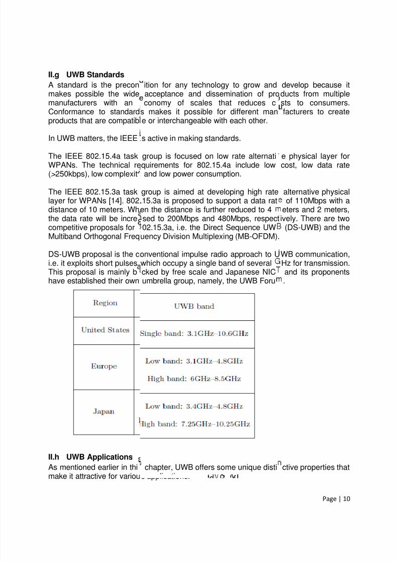
II.g UWB Standards
A standard is the preconmakes possible the widemanufacturers with anConformance to standardproducts that are compatibl
In UWB matters, the IEEE i
The IEEE 802.15.4a taskWPANs. The technical re(> 250kbps), low complexit
The IEEE 802.15.3a tasklayer for WPANs [14]. 802.distance of 10 meters. Whthe data rate will be increcompetitive proposals forMultiband Orthogonal Freq
DS-UWB proposal is the ci.e. it exploits short pulsesThis proposal is mainly bhave established their own
II.h UWB Applications
As mentioned earlier in thimake it attractive for variou
ition for any technology to grow andacceptance and dissemination of proconomy of scales that reduces c
s makes it possible for different mane or interchangeable with each other.
s active in making standards.
group is focused on low rate alternatiquirements for 802.15.4a include lowand low power consumption.
group is aimed at developing high rate.15.3a is proposed to support a data raten the distance is further reduced to 4sed to 200Mbps and 480Mbps, respect02.15.3a, i.e. the Direct Sequence UWuency Division Multiplexing (MB-OFDM).
onventional impulse radio approach to Uwhich occupy a single band of severalcked by free scale and Japanese NICumbrella group, namely, the UWB Foru
chapter, UWB offers some unique distis applications.
Page | 10
develop because itducts from multiplests to consumers.facturers to create
e physical layer forcost, low data rate
alternative physicalof 110Mbps with a
eters and 2 meters,ively. There are two
(DS-UWB) and the
WB communication,Hz for transmission.and its proponents.
ctive properties that

7/30/2019 CPW Antenna_Kesava Reddy
http://slidepdf.com/reader/full/cpw-antennakesava-reddy 11/31
Page | 11
Firstly, UWB has the potential for very high data rates using very low power at verylimited range, which will lead to the applications well suited for WPAN. The peripheralconnectivity through cable less connections to applications like storage, I/O devices andwireless USB will improve the ease and value of using Personal Computers (PCs) andlaptops. High data rate transmissions between computers and consumer electronics likedigital cameras, video cameras, MP3 players, televisions, personal video recorders,automobiles and DVD players will provide new experience in home and personalentertainment.
Secondly, sensors of all types also offer an opportunity for UWB to flourish. A sensornetwork is comprised of a large number of nodes within a geographical area. Thesenodes may be static, when applied for securing home, tracking and monitoring, ormobile, if equipped on soldiers, firemen, automobiles, or robots in military andemergency response situations. The key requirements for sensor networks include lowcost, low power and multi functionality which can be well met by using UWB technology.High data rate UWB systems are capable of gathering and disseminating or exchanginga vast quantity of sensory data in a timely manner. The cost of installation andmaintenance can drop significantly by using UWB sensor networks due to being devoidof wires. This merit is especially attractive in medical applications because a UWBsensor network frees the patient from being shackled by wires and cables whenextensive medical monitoring is required. In addition, with a wireless solution, thecoverage can be expanded more easily and made more reliable.
Thirdly, positioning and tracking is another unique property of UWB. Because of thehigh data rate characteristic in short range, UWB provides an excellent solution for
indoor location with a much higher degree of accuracy than a GPS. Furthermore, withadvanced tracking mechanism, the precise determination of the tracking of movingobjects within an indoor environment can be achieved with an accuracy of severalcentimeters [2]. UWB systems can operate in complex situations to yield faster andmore effective communication between people. They can also be used to find people orobjects in a variety of situations, such as casualties in a collapsed building after anearthquake, children lost in the mall, injured tourists in a remote area, fire fighters in aburning building and so on.
Lastly, UWB can also be applied to radar and imaging applications. It has been used inmilitary applications to locate enemy objects behind walls and around corners in the
battlefield. It has also found value in commercial use, such as rescue work where UWBradar could detect a person's breath beneath rubble, or medical diagnostics where X-ray systems may be less desirable.
UWB short pulses allow for very accurate delay estimates, enabling high definitionradar. Based on the high ranging accuracy, intelligent collision-avoidance and cruise-control systems can be envisioned. These systems can also improve airbag deploymentand adapt suspension/braking systems depending on road conditions. Besides, UWBvehicular radar is also used to detect the location and movement of objects near avehicle.

7/30/2019 CPW Antenna_Kesava Reddy
http://slidepdf.com/reader/full/cpw-antennakesava-reddy 12/31
III
The main objective of thisUWB communication systwith the fundamental antealways have to be considprimary requirements forapproaches to achieve widclassic UWB antenna confi
III.a. Definition of Ante
The antennas are an essStandard Definitions of te
radiating or receiving radiotakes the signals from a tand then broadcasts thereceive mode, the antennthem back into signals.
Fi
In an advanced wirelessaccentuate the radiation efrequencies. Thus the antedevice. In order to meet tresult, an antenna may bea lens, an assembly of elerelax system requirements
. Antenna Theory
thesis is to design antennas that are sms. Before the design work, it is necena theory in this chapter. Some impor
red in antenna design are described. Aa suitable UWB antenna are discus
e operating bandwidth of antenna are prgurations are introduced.
na
ential part of any wireless system. Accrms for Antennas, an antenna is defi
waves". In other words, a transmit antansmission line, converts them into elinto free space, as shown in Figurecollects the incident electromagnetic
gure: Antenna as a transition device
system, an antenna is usually requergy in some directions and suppress i
nna must also serve as a directional in ahe particular requirement, it must takea piece of conducting wire, an aperture,ents (arrays) and so on. A good desig
and improve overall system performanc
Page | 12
itable for the futuressary to get familiarant parameters thatthe same time, the
sed. Some generalesented. Also, some
ording to The IEEEed as a means for
nna is a device thatctromagnetic waves; while operating in
aves and converts
ired to optimize ort in others at certaindition to a transition
various forms. As aa patch, a reflector,of the antenna can
.

7/30/2019 CPW Antenna_Kesava Reddy
http://slidepdf.com/reader/full/cpw-antennakesava-reddy 13/31
Page | 13
III.b. Important Parameters of Antenna
To describe the performance of an antenna, definitions of various parameters are
necessary. In practice, there are several commonly used antenna parameters, includingfrequency bandwidth, radiation pattern, directivity, gain, input impedance, and so on.
III.b.i Frequency Bandwidth
Frequency bandwidth (BW ) is the range of frequencies within which the performance ofthe antenna, with respect to some characteristic, conforms to a specified standard. Thebandwidth can be considered to be the range of frequencies, on either side of the centerfrequency, where the antenna characteristics are within an acceptable value of those atthe center frequency. Generally, in wireless communications, the antenna is required toprovide a return loss less than -10dB over its frequency bandwidth.
The frequency bandwidth of an antenna can be expressed as either absolute bandwidth (ABW ) or fractional bandwidth (FBW ). If fH and fL denote the upper edge and thelower edge of the antenna bandwidth, respectively. The ABW is defined as thedifference of the two edges and the FBW is designated as the percentage of thefrequency difference over the center frequency, as given in Equations respectively.
= –
= 2( – )/( + )
For broadband antennas, the bandwidth can also be expressed as the ratio of the upperto the lower frequencies, where the antenna performance is acceptable, as shown inEquitation.
= /
III.b.ii Radiation Pattern
The radiation pattern (or antenna pattern) is the representation of the radiationproperties of the antenna as a function of space coordinates. In most cases, it isdetermined in the far field region where the spatial (angular) distribution of the radiatedpower does not depend on the distance. Usually, the pattern describes the normalized
field (power) values with respect to the maximum values.The radiation property of most concern is the two- or three-dimensional (2D or 3D)spatial distribution of radiated energy as a function of the observer's position along apath or surface of constant radius. In practice, the three-dimensional pattern issometimes required and can be constructed in a series of two-dimensional patterns. Formost practical applications, a few plots of the pattern as a function of ' for someparticular values of frequency, plus a few plots as a function of frequency for someparticular values of µ will provide most of the useful information needed, where ' and µ are the two axes in a spherical coordinate.

7/30/2019 CPW Antenna_Kesava Reddy
http://slidepdf.com/reader/full/cpw-antennakesava-reddy 14/31
Page | 14
For a linearly polarized antenna, its performance is often described in terms of itsprinciple E plane and H -plane patterns. The E -plane is defined as the plane containingthe electric field vector and the direction of maximum radiation whilst the H -plane isdefined as the plane containing the magnetic-field vector and the direction of maximumradiation.
There are three common radiation patterns that are used to describe an antenna'sradiation property:
Isotropic Directional Omni directional
III.b.iii Directivity and Gain
To describe the directional properties of antenna radiation pattern, directivity D isintroduced and it is defined as the ratio of the radiation intensity U in a given directionfrom the antenna over that of an isotropic source. For an isotropic source, the radiationintensity U 0 is equal to the total radiated power Prad divided by 4π. So the directivitycan be calculated by:
=U
0=
4πU
If not specified, antenna directivity implies its maximum value, i.e. D 0.
0 =|
Uo=
Uo=
4πU
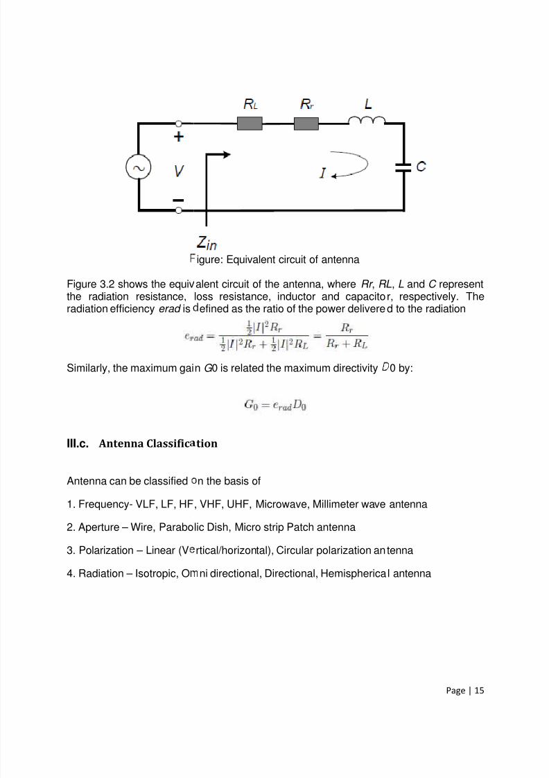
Antenna gain G is closely related to the directivity, but it takes into account the radiationefficiency erad of the antenna as well as its directional properties, as given by:
G= e rad D
7/30/2019 CPW Antenna_Kesava Reddy
http://slidepdf.com/reader/full/cpw-antennakesava-reddy 15/31
Figure 3.2 shows the equivthe radiation resistance,radiation efficiency erad is
Similarly, the maximum gai
III.c. Antenna Classific
Antenna can be classified
1. Frequency- VLF, LF, HF
2. Aperture – Wire, Parabo
3. Polarization – Linear (V
4. Radiation – Isotropic, O
igure: Equivalent circuit of antenna
alent circuit of the antenna, where Rr , R loss resistance, inductor and capacito
efined as the ratio of the power delivere
n G 0 is related the maximum directivity
tion
n the basis of
, VHF, UHF, Microwave, Millimeter wave
lic Dish, Micro strip Patch antenna
rtical/horizontal), Circular polarization an
ni directional, Directional, Hemispherica
Page | 15
L, L and C representr, respectively. Thed to the radiation
0 by:
antenna
tenna
l antenna

7/30/2019 CPW Antenna_Kesava Reddy
http://slidepdf.com/reader/full/cpw-antennakesava-reddy 16/31
III.c.i Frequency Basic
1. Very Low Frequency (Vloaded Monopoles, T and Ispan antenna.2. Medium Frequency (Mantennas.3. High Frequency (HF) anCone antennas, Vertical w4. Very High Frequency
antennas, log periodic anantennas, parabolic anten5. Super High Frequency (Parabolic antenna, pyramiantennas, Micro strip patch
LF) & Low frequency (LF) antenna: Vernverted L antennas, Triatic antenna, Tri
) antennas: Radiators (monopoles and
ennas: Log periodic antenna, conical mip antenna, rhombic antenna, Fan dipolVHF) & Ultra High Frequency (UHF)
ennas, helical antennas, Panel antennas, discone antennas,HF) & Extremely High Frequency (EHF)al horn antennas, discone antennas, mantennas, fractal antennas.
Page | 16
tical Radiators, Top-eco antenna, Valley
dipoles), directional
nopole and Invertedantenna.
antennas: Yagi-Uda
as, Corner reflectorantennas:nopoles and dipoles

7/30/2019 CPW Antenna_Kesava Reddy
http://slidepdf.com/reader/full/cpw-antennakesava-reddy 17/31
III.c.ii Aperture Antenna
Aperture antennas transmi
• Wire antennas• Horn Antenna• Parabolic reflectiv• Cassegrain antenn
• Wire antennas A wire antenna is simpl(monopole antenna), wherbe a loop antenna suchradiators are come in to wiwire antenna.
• Horn AntennaA horn antenna maybe regis capable of radiating radend and open at the otherproduced. Flaring in the dirplane horn and sectorial Hboth walls (E and H) of thflaring the walls of a circula
Figu
• Parabolic reflective antA parabola is a two dimencurved surface. Thereforeaxis. The surface so gen“microwave dish” or “parabprimary antenna such asreflector. The important pr
s
and receive energy from its aperture.
antennaa
a straight wire of length ë/2 (dipolë is the transmitted signal wavelength.
s circular loop, rectangular loop, etc.e antenna categories. A whip antenna is
arded as a flared out or opened out waviation into open space provided the saend. If flaring is done in one direction, tection of Electric vector and Magnetic vplane Horn are obtained respectively. Ifrectangular waveguide, then pyramidal
r waveguide, a conical horn is formed.
re: Corrugated conical horn antenna
nnaional plane curve. A practical reflector is
practical reflector is formed by rotatingerated is known as “paraboloid” whicolic reflector”. The paraboloid reflector aa dipole or horn situated at the focal pctical implication of this property is tha
Page | 17
antenna) and ë/4A wire antenna can
Basically all verticalthe best example of
guide. A waveguidee is excited at one
hen sectorial horn isctor, the sectorial E-flaring is done alonghorn is obtained. By
a three dimensionala parabola about its
is often called asntenna consists of aoint of a paraboloidt reflector can focus

7/30/2019 CPW Antenna_Kesava Reddy
http://slidepdf.com/reader/full/cpw-antennakesava-reddy 18/31
parallel rays on to the focradiations originating from
• Cassegrain antenna
In cassegrain antenna privertex of the paraboloidhyperboloid secondary reparaboloid. The feed radireflector. As such, thecassegrain secondary reflehad originated from the fusual.
In spacecraft or aircraft ainstallation, and aerodynaIn order to meet these santennas can be flush mouspace for the feed line wdisadvantages of patch orbandwidth which is typicall
III.c.iii Polarization Basi
Antenna polarization is goon that:
1. Linearly (Verticall2. Circularly Polariz
1. Linearly (Vertically/HoIf antenna is transmitting/ vertically polarized antennthen antenna is said to be
Figure:
al point or conversely it can produce ahe focal point.
ary feed radiator is positioned aroundinstead of at focus. Cassegrain feedlector whose one of the foci coincidetor is aimed at the secondary hyperboladiations emitted from feed radiatorctor which illuminates the main parabolocus. Then the paraboloid reflector colli
plications, where size, weight, cost, pic profile are constraints, low profile an
pecifications Micro strip Patch antennnted to metal or other existing surfacesich is normally placed behind the groumicro strip antennas are their inefficieonly a fraction of a percent or at the mo
s
erned by the polarization of Electroma
/Horizontally) Polarized antenna.d antenna.
izontally) Polarized antennaeceiving Vertical E field vector, then a. If antenna is transmitting/receiving horiorizontally polarized antenna.
xamples of linearly polarized antenn
Page | 18
parallel beam from
n opening near thesystem employs a
s with the focus ofoid reflector or sub-are reflected from
id reflector as if theyminates the rays as
rformance, ease oftennas are required.s are used. Thesend they only required plane. The majorcy and very narrowst a few percent.
netic waves. Based
tenna is said to bezontal E field vector,
s

7/30/2019 CPW Antenna_Kesava Reddy
http://slidepdf.com/reader/full/cpw-antennakesava-reddy 19/31
2. Circularly Polarized an
If the antenna is able to
antenna is said to be circul
Figure:
III.c.iv Radiation Patter
On the basis of radiation p1. Isotropic antenn2. Omni directional3. Directional anten4. Hemispherical a
1. Isotropic antenna
An isotropic antenna is a fiuniformly in all directions. I
or simply unipole. An isotrthe practical antennas areantenna. Although sometiantenna but these days usus assume that practical aantenna is three times moconnected with same sour
enna
transmit or receive E field vectors of
rly polarized antenna.
xamples of circular polarized antenn
Basis
ttern antenna can be classified as:.antenna.na.tenna.
ctitious antenna and is defined as an anis also called as isotropic source or om
opic antenna is a hypothetical losslesscompared. Thus an isotropic antenna ies, a half-wave dipole antenna is als
e of isotropic antenna as reference antentenna is having a gain of 3dBi meansre than that of isotropic antenna whene.
Page | 19
ny orientation, then
s
enna which radiatesidirectional antenna
antenna, with whichs used as referenceused as reference
nna is preferred. Lethat gain of practicaloth the antenna are

7/30/2019 CPW Antenna_Kesava Reddy
http://slidepdf.com/reader/full/cpw-antennakesava-reddy 20/31
2. Omni directional anten
Omni directional antennas
direction and having somantennas are having OmnDipoles antennas, etc. Thbelow.
3. Directional antenna
Antennas which directs itantennas. These antennawireless distance. Examplperiodic antenna, etc. Radi
Fi
na
are those antennas which will cover eq
e angle in elevation direction. Basicali directional radiation pattern. Example
radiation patterns of Omni directional
igure: Omni Directional antenna
energy in one particular direction is sare having very high gain and direcs are paraboloid reflector antenna, Ya
ation pattern of these antennas are sho
gure: Directional radiation pattern
Page | 20
ually well in azimuth
ly most of the wireare Whip antenna,ntennas are shown
aid to be directionaltivity to cover largei-Uda antenna, Logn below.

7/30/2019 CPW Antenna_Kesava Reddy
http://slidepdf.com/reader/full/cpw-antennakesava-reddy 21/31
4. Hemispherical antenna Antenna whose radiation phemisphere or lower hemipattern. Such types are ahemisphere for data linkground plane. The radiatio
Figu
III.d. Requirements for
As is the case in conventia crucial role in UWB syUWB antenna than a narro
First of all, what distinguifrequency bandwidth. Accobe able to yield an absolutat least 0.2.
Secondly, the performancentire operational band. Imatching should be stabletheUWB antenna provides thband devices and services
Thirdly, directional or Omthe practical application. Ohand-held systems. For radesired, directional radiatio
attern will cover the one half of the hemsphere is said to be antenna with Hetennas are implemented on aircraft bodurpose. Examples are all Monopolespattern of these antennas is shown bel
re: Hemispherical antenna radiation
UWB Antenna
nal wireless communication systems, atems. However, there are more challew band one.
hes a UWB antenna from other antenrding to the FCC's definition, a suitablebandwidth no less than 500MHz or a fr
of a UWB antenna is required to beIdeally, antenna radiation patterns, gaacross the entire band. Sometimes, it is
e band-rejected characteristic to coexisoccupying the same operational band.
i-directional radiation properties are nmni-directional patterns are normally dear systems and other directional system
n characteristics are preferred.
Page | 21
isphere either upperispherical Radiationy to cover the lowerantennas with largew.
antenna also playsges in designing a
nas is its ultra wideWB antenna shouldctional bandwidth of
consistent over theins and impedancealso demanded that
t with other narrow-
eded depending onirable in mobile ands where high gain is

7/30/2019 CPW Antenna_Kesava Reddy
http://slidepdf.com/reader/full/cpw-antennakesava-reddy 22/31
Page | 22
Fourthly, a suitable antenna needs to be small enough to be compatible to the UWB unitespecially in mobile and portable devices. It is also highly desirable that the antennafeature low profile and compatibility for integration with printed circuit board (PCB).
Fifthly, a good design of UWB antenna should be optimal for the performance of overallsystem. For example, the antenna should be designed such that the overall device(antenna and RF front end) complies with the mandatory power emission mask given bythe FCC or other regulatory bodies.
Lastly, but not the least important, a UWB antenna is required to achieve good timedomain characteristics. For the narrow band case, it is approximated that an antennahas same performance over the entire bandwidth and the basic parameters, such asgain and return loss, have little variation across the operational band. In contrast, UWBsystems often employ extremely short pulses for data transmission. In other words,enormous bandwidth has been occupied. Thus the antenna can't be treated as a spotfilter" any more but a band-pass filter". In this case, the antenna imposes moresignificant impacts on the input signal. As a result, a good time domain performance, i.e.minimum pulse distortion in the received waveform, is a primary concern of a suitableUWB antenna because the signal is the carrier of useful information. Therefore, it isindispensable and important to study the antenna's characteristics in time domain.

7/30/2019 CPW Antenna_Kesava Reddy
http://slidepdf.com/reader/full/cpw-antennakesava-reddy 23/31
Page | 23
IV. Numerical Methods
Typical numerical methods for modeling CPW structures are given below• Finite Difference Method (FDM)• Finite Element Method (FEM)• Transmission Line Matrix Method (TLM)• Integral Equation Method• Method of Moment (MOM)• Mode Matching Method• Transverse Resonance Method (TRM)• Method of Lines (MOL)• Generalized S Matrix Method• Spectral Domain Method
IV.a. Method of Moments
The below steps describes the MOM approach
• Divide a Circuit in to small subsections.
• One sub section is taken at a time and calculate the electric field generatedeverywhere by the current on at one section. Then for each subsection.
• Place current on all subsections simultaneously and adjust those currents so thattotal tangential Electric field goes to Zero.
• Once the Current distribution is obtained, the S parameters follow immediately.
IV.b. Software Tools
Generally used software tools for modeling the CPW structures which are developed byusing some of the above mentioned numerical methods are given below.
• IE3D (MOM)
• HFSS (FEM)
• ADS (FEM)
• Fidelity (FDTD)
In this paper we are using MOM based IE3D software tool for simulating the antenna.

7/30/2019 CPW Antenna_Kesava Reddy
http://slidepdf.com/reader/full/cpw-antennakesava-reddy 24/31
Page | 24
V. Antenna Design and Results
Design and analysis of a compact coplanar waveguide (CPW) fed Ultra Wideband(UWB) slot antenna is presented in this paper. The antenna consists of a rectangularslot with cross like structure at the anterior portion of the feed which acts as tuning stub.The CPW feed is designed for 50- impedance. The physical dimension of the proposedantenna is 18mm (length) × 17mm (width) × 1.6mm (thickness). The characteristics ofthe designed structure are investigated by using MOM based electromagnetic solver,IE3D. An extensive analysis of the proposed antenna in the frequency and timedomains is presented. The antenna was fabricated with FR4 substrate andcharacterized by measuring return loss, radiation pattern and gain. The measuredresults are appreciably in good agreement with the simulated ones. A better impedancebandwidth is obtained from 4.8 GHz to 12.8 GHz that constitutes a fractional bandwidth
of 90% with return loss less than or equal to - 10 dB (VSWR≤
2). Time domain analysisof the antenna is also performed, which witnessed the linear phase and less distortion.The simple configuration and low profile nature of the proposed antenna leads to easyfabrication that may be built for any wireless UWB device applications.
V.a. Antenna Design
The structure of the antenna is shown in Fig. The parameters `W 1' and `L1' are thewidth and length of the rectangular slot, `W 2', `W 3'. `L2' and `L3' are the widths andlengths of the cross stub. `H ' is the distance between the patch and feed line. `W ' and`L' are the width and length of the whole antenna respectively. In this study, a dielectricsubstance (FR4) with thickness of 1.6mm and a relative permittivity of 4.4 is chosen assubstrate. The CPW feed is designed for a 50Ω characteristic impedance with fixed1.8mm feed line width and 0.3mm ground gap. The proposed antenna produces widebandwidth with Omni-directional radiation pattern. The wide bandwidth and impedancematching with reduced size of the antenna is achieved due to resultant of differentsurface magnetic currents.

7/30/2019 CPW Antenna_Kesava Reddy
http://slidepdf.com/reader/full/cpw-antennakesava-reddy 25/31
Figure: Geometry
V.b. Simulated Results
In this section, various parUWB antennas are carrieperformed for the best iantenna are listed in Table.in Fig, which clearly indic(11.8 GHz 13.8 GHz) fordue to the coupling betwfrequency and bandwidth
tuning stub. Proper geomvariation of field distributioantenna.
f the proposed CPW-fed rectangular
Analysis
ametric analyses of the antenna whichd out and presented. The analysis anpedance bandwidth. The optimal para
. The simulated return loss of the propostes that the impedance bandwidth of tha return loss (S 11) less than - 10 dB. Ten the rectangular slot and the tuningre controlled by the size of the rectangu
etrical selection of the antenna paramn, which in turn affects the characteris
Page | 25
lot antenna.
re inevitable for anyd optimization were
eter values of thed antenna is shown
e antenna is 2 GHze ultra wideband isstub. The resonant
lar slot, antenna and
eters results in theics of the proposed

7/30/2019 CPW Antenna_Kesava Reddy
http://slidepdf.com/reader/full/cpw-antennakesava-reddy 26/31
Figure: Simulated return loss of the proposed ant
Figure: 2D Pattern
Page | 26
enna.

7/30/2019 CPW Antenna_Kesava Reddy
http://slidepdf.com/reader/full/cpw-antennakesava-reddy 27/31
Figure
Figure: T
: Total Field Gain of proposed antenn
tal Field Directivity of proposed ante
Page | 27
na

7/30/2019 CPW Antenna_Kesava Reddy
http://slidepdf.com/reader/full/cpw-antennakesava-reddy 28/31
Figure:
Fi
ntenna efficiency of proposed anten
gure: VSWR of proposed antenna
Page | 28
a

7/30/2019 CPW Antenna_Kesava Reddy
http://slidepdf.com/reader/full/cpw-antennakesava-reddy 29/31
Figu
V.c. Conclusion
This design describes theThe antenna has a uniquenhance the coupling betwoverall dimension of the(width) × 1.6mm (thicknessto ensure the suitability ofproposed antenna is simplsystems.
e: Smith chart for proposed antenna
etailed analysis and implementation ofcross like tuning stub at the anterior p
een the slot and feed. With the above sproposed antenna comes around 18m). The time domain analysis of the antenthe proposed antenna for the UWB ene, easy to fabricate and can be integra
Page | 29
a CPW fed antenna.ortion of the feed toructural features the
(length) × 17mmna is also performedironment. Thus, theed into any satellite

7/30/2019 CPW Antenna_Kesava Reddy
http://slidepdf.com/reader/full/cpw-antennakesava-reddy 30/31
Page | 30
VI. Future Work and Conclusion
V.a. Conclusion
The Ku band is a portion of the electromagnetic spectrum in the microwave range offrequencies. This symbol refers to (originally German: Kurz-unten )—in other words, theband directly below the K-band. In radar applications, it ranges from 12-18 GHz according to the formal definition of radar frequency band nomenclature in IEEEStandard 521-2002. This is due to its ability to achieve very high data rate which resultsfrom the large frequency spectrum occupied. Besides, extremely low power emissionlevel will prevent Ku band systems from causing severe interference with other wirelesssystems. As the only non- digital part of a Ku band system, antenna remains as a
particular challenging topic because there are more stringent requirements for a suitableKu band antenna compared with a narrowband antenna. Therefore, the antenna designand analysis for Ku band systems were carried out in this survey paper.
V.b. Future Work
In this survey paper we concentrate on antenna theory and its design using simulationtool like IE3D which is based on Moment of Methods (MOM). Here we proposed a newdesign for Ku band applications like broadcasting satellite services and get the accurateresults. In future we are going to fabricate the designed antenna and proposed new
designs for micro wave frequency band applications using HFSS software tool which isbased on Finite Element Method (FEM).

7/30/2019 CPW Antenna_Kesava Reddy
http://slidepdf.com/reader/full/cpw-antennakesava-reddy 31/31
Page | 31
References
[1] J. G. Proakis, Digital Communications", New York: McGraw-Hill, 1989.[2] FCC, First Report and Order 02-48. February 2002.[3] Federal Communications Commission Revision of Part 15 of the Commission‘s
Rules Regarding Ultra-Wideband Transmission System from 3.1 to 10.6 GHz, inFederal Communications Commission. Washington, DC: ET-Docket, 2002, pp. 98–153, FCC.
[4] I. Oppermann, M.Hamalainen and J.Linatti “UWB Theory and Applications”, © 2004, john Willy & Sons, Ltd.
[5] Raha Eshtiaghi & RezaZaker “antenna and it’s applications”, DRDO scienceSpectrum, march 2009, PP 66-78 © 2009
[6] J. William and R. Nakkeeran “A Compact CPW-fed UWB slot antenna with crosstuning stub”, Progress in Electromagnetic Research, V0l.13, 159-170,210.[7] “UWB Semi-elliptical printed monopole antenna with sub band rejection filter”,
Science Direct, Int. J.Electron.Commun. (AEU) 64 (2010) 133-141.[8] Warren L. Stutzman & Gary A. ThIele, “Antenna Theory and Design”, © 1998, John
Willy & Sons, Ltd.[9] Saber Soltani, “Two novel very small monopole antennas having frequency band
notch function using DGS for UWB application”, Science Direct, Int.J.Electron.Commun. (AEU) 65 (2011) 87-94.
[10] V.A. Shameena & S. Mridula, “A compact CPW fed slot antenna for ultra wide bandapplications”. Int. J. Electron. Commun. (AEÜ) 66 (2012) 189–194
[11]http://ahfr.dit.ie/ [12]http://parc.wustl.edu/research [13]http://www.ara-inc.com/index.xml [14]http://www.elec.qmul.ac.uk/antennas/index.html [15]http://arrow.dit.ie/ahfrccon/