broadband cpw fed polarization reconfigurable …
TRANSCRIPT

ISSN: 2395-1680 (ONLINE) ICTACT JOURNAL ON MICROELECTRONICS, JULY 2021, VOLUME: 07, ISSUE: 02
DOI: 10.21917/ijme.2021.0196
1127
BROADBAND CPW FED POLARIZATION RECONFIGURABLE ANTENNA FOR
UNIVERSAL UHF RFID READER
Sateesh Virothu and M. Satya Anuradha Department of Electronics and Communication Engineering, Andhra University College of Engineering, India
Abstract
In this paper, a compact CPW fed polarization reconfigurable
wideband antenna is presented for the application of a universal ultra-
high frequency (UHF) radio frequency identification (RFID) antenna.
In this work, long-range and random orientation detectability features
are incorporated with the inclusion of polarization reconfigurability in
the RFID reader antenna. Initially, a circularly polarized antenna is
designed, which consists of a square slot embedded with an inverted L-
shaped strip line and an F-shaped feeding structure, which is etched
on the FR4_epoxy substrate. Secondly, the inclusion of three PIN
diodes and an extra strip line connected to the feed structure are used
to achieve linear as well as circular polarization. The desired
performance is obtained in the whole UHF RFID frequency band
(universally adopted range in the UHF band by the different countries)
from 840 MHz to 960 MHz. Simulation, as well as experimentation
procedures, are applied to obtain the details of the S11, gain, axial ratio,
and radiation patterns. The experimented performance metrics are in
good agreement with simulation results. The results reveal that axial
ratio requirements for linear and circular polarizations are met in the
required band of operation with accepTable.gain.
Keywords:
RFID, Polarization Reconfigurable Antenna, CPW Feed, PIN Diodes,
UHF Band
1. INTRODUCTION
RFID with CP operation has been extensively used in various
applications such as the internet of things (IOT), manufacturing
industries, and goods in flow systems. Different countries utilize
distinct frequency bands authorized for UHF RFID applications.
The frequency ranges for UHF RFID applications are 865–867
MHz in India, 866–869 MHz in Europe, 920–926 MHz in
Australia, 902–928 MHz in North America, 908.5–914 MHz in
Korea, 840.5–844.5 MHz, and 950–956 MHz in Japan, and
920.5–924.5 MHz in China and so on.
Numerous wideband CPW fed square slot antennas have been
discussed in the literature. A CPW fed square slot antenna for
broadband applications has been presented. The location, width,
and length of the tuning stub are varied to obtain optimal
impedance bandwidth of 60% [1]. Further improvement in the
impedance bandwidth has been achieved with metallic strips
added at the corners of the square slot, with the suitable ratio of
the metallic strip in the slot to loading metallic strips [2]. Photonic
bandgap structures with square-shaped or cross-shaped structures
have been implemented in a loop slot, to suppress harmonic
control as well as enhancing the bandwidth [3]. Coplanar
waveguide (CPW) feed technique used by antennas exhibit many
advantages over basic microstrip antennas, like lower dispersion
and radiation loss, broader bandwidth, ease of fabrication using
MMIC and conformability made the antennas most prevalent [4].
In several communication systems CP antennas play an
important role, which eliminates polarization mismatch for
various alignment of equipment, also gives benefits such as
resistance to unsuitable weather conditions and the reduction in
multipath losses. Due to these features, many CP antennas have
been implemented in the previous works. The broadband CP
operation is experimentally demonstrated by connecting a T-
shaped metallic strip to the ground plane at an angle 900 to the
feed line [5]. CP mechanism has been introduced with a square
slot, inductively coupled with slots and cuts [6], and a ‘C’ shaped
grounded strip with diagonal slots has been implemented [7].
The RFID system comprises of the reader and the tags that
contain particular information of the objects they are attached.
Electromagnetic waves are used to identify and tracking of objects
[8]. Many wideband UHF RFID reader antennas with CP
operation have been experimentally discussed in previous
publications. In [9], Circular polarization and size reduction are
achieved by arranging two asymmetric Koch fractal geometries
with the single-probe-feed square radiator. Further, four arrow-
shaped slots are introduced in diagonal axes of the square radiator
to tune resonant frequency around the UHF range. In [10], a
frequency reconfigurable UHF RFID reader antenna has been
practically tested, and CP radiation is introduced with two L
shaped short patches attached to two L shaped radiating strips
using PIN diodes. By applying biasing to PIN diodes, the antenna
can radiate CP at the two anticipated frequency bands. The overall
UHF RFID frequency range 840-960 MHz has been covered with
CP operation by utilizing a square slot and F-shaped feeding
structure with, an inserted arc-shaped strip [11], a spur line added
along the diagonal to the square slot [12], and a T-shaped strip
line and three stubs connected to the ground [13]. A CPW fed
circular slot with an L-shaped feeding configuration, and two strip
lines of L-shaped are placed in the circular slot connected to the
ground plane has been practically investigated to achieve
broadband impedance bandwidth in CP operation [14].
Some of the research contributions on polarization
reconfigurable antennas have been demonstrated for RFID, Wi-
Fi, Wi-MAX, and WLAN applications. Switching PIN diodes in
on/off conditions linear, left-hand, and right-hand circular
polarization modes are achieved for distinct applications [15-21].
Concentrated emissions in LP antennas provide a higher reader
range compared to CP antennas exhibiting the same gain. The CP
antennas have shorter ranges because the radiated power is
distributed in two planes, and are suitable for applications where
the tags are oriented in random directions.
The reader antennas of RFID system designed in the operating
band of 840 to 960 MHz would be useful for universal
applications, which reduce cost-effectiveness. An RFID reader
antenna exhibiting both linear and circular polarization is
preferable to cover most of the applications. A CPW fed RFID
reader with reconfigurable linear and circular polarizations in the
UHF band is not published in earlier works. In the present work,
a polarization reconfigurable RFID reader antenna has been

SATEESH VIROTHU AND M SATYA ANURADHA: BROADBAND CPW FED POLARIZATION RECONFIGURABLE ANTENNA FOR UNIVERSAL UHF RFID READER
1128
investigated. To achieve the desired UHF RFID reader antenna
performance, a CPW fed square slot antenna with an F-shaped
feeding structure, embedded inverted L-shaped stripline to the
ground, three PIN diodes, and an extra strip line connected to the
feed are utilized in the proposed antenna design. The design
covers the complete UHF RFID range from 840 MHz to 960
MHz.
The rest of the paper is organized with the following sections:
section 2 discussed antenna design considerations. In part 3
discussed the simulated and experimental results. Finally, the
conclusion is presented in section 4.
2. ANTENNA DESIGN CONSIDERATION
The compact polarization reconfigurable antenna geometry
with three PIN diodes (D1, D2, and D3) is illustrated in Fig.1(a).
And the fabricated antenna is shown in Fig.1(b). The optimal
proposed antenna dimensions are presented in Table.1. The
antenna is printed on an FR4_epoxy substrate (εr = 4.4, h = 0.8
mm and dielectric loss tangent = 0.02), and its overall dimension
is 114×114×0.8 mm3. Initially, the operating frequency 890 MHz
calculated using Eq.(1),
2 2
2c
reff
c m nf
p q
= +
(1)
where c is 3×10⁸ m/s, εreff is the effective permittivity of the
substrate, p and q are sizes of the square slot. The dimension of
the radiating square slot is 86×86mm2.
The antenna structure is excited with an F-shaped feeding
configuration is depicted in Fig.1. The dimensions L2 and L3
contribute TE10 and TE01 modes respectively, CP radiation can
be produced with two orthogonal modes of equal magnitude and
a phase difference of 900. Incorporating an inverted L-shaped
stripline connected to the ground in the square slot, which disturbs
surface electric field distribution, and hence, circularly polarized
modes are excited. The length L4 acts as a stub to produce the
broader resonating bandwidth. In order to obtain polarization
reconfigurability, an extra strip line is embedded to the feed
structure using PIN diode D1, and PIN diodes D2 and D3 are placed
in an inverted L-shaped strip line.
(a)
(b)
Fig.1. (a) Detailed dimensions of the designed antenna (b)
Fabricated prototype
Applying the biasing voltages to these three PIN diodes, both
circular and linear polarized waves can be radiated. Circular
polarization can be obtained when D1 OFF, D2, and D3 ON, and
linear polarization can be obtained when D1 ON, D2, and D3 OFF.
To reduce the effect of external bias voltage on antenna
performance, three 10 µF and two 100 µF dc blocking capacitors,
and six 3.3 KΩ resistors are used in the configuration. BAR64
series PIN diodes are used for switching action. From the
datasheet specifications, in the on-state, the diode exhibits 3.1Ω
resistance in series with 1.8 nH inductance, and 1.8 nH inductance
in series with the parallel combination of 3.4 KΩ resistance and
0.2 pF capacitance in the off-state as shown in Fig.2.
Table.1. Optimum Antenna Dimensions
Dimension Value
(mm) Dimension
Value
(mm)
W 114 L5 40
L 114 L6 47
W1 14 G 0.4
W2 7.5 G1 0.5
W3 8 Wf 1.48
W4 2 Ld 1
L1 14 Wd 1.25
L2 27 Lc 1
H 0.8 Wc 1.25
L3 38 Lr 0.5
L4 39.5 Wr 0.4
Fig.2. BAR 64-03W PIN diode equivalent circuit

ISSN: 2395-1680 (ONLINE) ICTACT JOURNAL ON MICROELECTRONICS, JULY 2021, VOLUME: 07, ISSUE: 02
1129
3. RESULTS AND DISCUSSION
3.1. SIMULATION RESULTS
To achieve the universal RFID reader antenna performance,
three evolution processes of the proposed reconfigurable antenna
are presented in Fig.3. These designs are simulated by using
Ansys HFSS software. Fig.4 illustrates simulation results of the
reflection coefficient, axial ratio, and gain characteristics. The
first evolution (Ant. 1) of the RFID antenna comprises of an F-
shaped feeding structure, which exhibits a -10dB impedance
bandwidth in the frequency band of 780 MHz to1070 MHz with
a percentage impedance BW of 31.35%. This configuration
produces poor CP radiation, as can be seen from Fig.3 (c) axial
ratio characteristics.
(a) (b) (c)
Fig.3. The geometric evolution of the reconfigurable antenna. (a)
Ant.1 (b) Ant. 2 (c) Ant.3 (Proposed)
(a)
(b)
(c)
Fig.4. Simulated plots of designed antenna structures. (a)
Reflection Coefficient (b) Axial ratio (c) Gain.
CP radiation is improved in the second evolution process (Ant.
2), an extra inverted L-shaped stripline is placed in the square slot
and connected to the ground. This design achieves a -10dB
resonating bandwidth of 300 MHz (percentage impedance BW of
32.60%). This design radiates circularly polarized waves having
a 3dB axial ratio of 290 MHz in the frequency band of 840 MHz
to 1130 MHz.
In the final evolution process (Ant. 3), three PIN diodes and a
stripline are incorporated to produce circular as well as linear
polarized waves with proper biasing to PIN diodes. This proposed
design (Ant. 3) produces circular polarization when D1 OFF, D2,
and D3 ON. In this case, the simulated S11 is less than -10dB over
the frequency band of 700 to 1070 MHz. It achieves a 3dB axial
ratio bandwidth of 290 MHz over a frequency band of 840 MHz
to 1130 MHz, with an AR bandwidth (3dB) of 29.44%.
The same antenna structure (Ant. 3) produces linear
polarization when D1 ON, D2, and D3 OFF, and provides dual-
band -10dB impedance bandwidth in the frequency range of < 700
MHz to760 MHz and 810 MHz to1060 MHz. In the desired band,
the percentage impedance BW of 26.7% is obtained and exhibits
an axial ratio value of more than 14dB. All the antenna structures
radiate with similar gain values except Ant. 3 in LP mode radiates
less gain in the required operating band.
Simulated 2D radiation plots are illustrated In Fig.5, and
RHCP/LHCP radiation patterns of Ant. 2 and Ant. 3 in CP mode
at 890 MHz in the XOZ and YOZ planes are presented in Fig.6.
From these figures, it is observed that RHCP and LHCP are
radiated along the +z and -z directions, respectively, which shows
good symmetry in both directions.
The vector electric field distributions of the proposed Ant. 3
in CP mode at 890 MHz structure for different phase angles (00,
900, 1800, and 2700) are illustrated in Fig.7. These field
distributions are observed at a distance of 𝜆0/4 from the antenna
structure. Electric field vectors at 00 phase angle show that the
predominant radiating vectors are in the direction of ‘-x and -y’,
for 900, 1800, and 2700 they are directed in ‘-y and +x’, ‘+x and
+y’, and ‘+y and -x’ respectively. In other words, after each
quarter-period, the electric field vectors rotate in the counter
clockwise direction by 900 in the +z direction, which explains
SATEESH VIROTHU AND M SATYA ANURADHA: BROADBAND CPW FED POLARIZATION RECONFIGURABLE ANTENNA FOR UNIVERSAL UHF RFID READER
1130
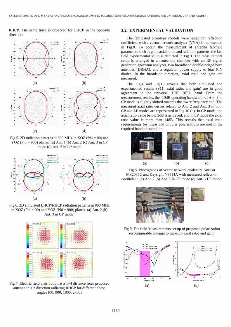
RHCP. The same trace is observed for LHCP in the opposite
direction.
(a) (b)
(c) (d)
Fig.5. 2D radiation patterns at 890 MHz in XOZ (Phi = 00) and
YOZ (Phi = 900) planes. (a) Ant. 1 (b) Ant. 2 (c) Ant. 3 in CP
mode (d) Ant. 3 in LP mode
(a) (b)
Fig.6. 2D simulated LHCP/RHCP radiation patterns at 890 MHz
in XOZ (Phi = 00) and YOZ (Phi = 900) planes. (a) Ant. 2 (b)
Ant. 3 in CP mode.
Fig.7. Electric field distribution at a λ0/4 distance from proposed
antenna in + z direction radiating RHCP for different phase
angles (00, 900, 1800, 2700)
3.2. EXPERIMENTAL VALIDATION
The fabricated prototype models were tested for reflection
coefficient with a vector network analyzer (VNA) is represented
in Fig.8. To obtain the measurement of antenna far-field
parameters such as gain, axial ratio, and radiation patterns, the far-
field experimental setup is depicted in Fig.9. The measurement
setup is arranged in an anechoic chamber with an RF signal
generator, spectrum analyzer, two broadband double-ridged horn
antennas (DRHA), and a regulator power supply to bias PIN
diodes. In the broadside direction, axial ratio and gain are
measured.
The Fig.4 and Fig.10 reveals that both simulated and
experimented results (S11, axial ratio, and gain) are in good
agreement in the universal UHF RFID band. From the
measurement results, the -10dB operating bandwidth of Ant. 3 in
CP mode is slightly shifted towards the lower frequency end. The
measured axial ratio curves related to Ant. 2 and Ant. 3 in both
CP and LP modes are represented in Fig.10 (b). In CP mode, the
axial ratio value below 3dB is achieved, and in LP mode the axial
ratio value is more than 14dB. This reveals that axial ratio
requirements for linear and circular polarizations are met in the
required band of operation.
(a) (b) (c)
Fig.8. Photographs of vector network analyzers Anritsu
MS2037C and Keysight N9914A with measured reflection
coefficient. (a) Ant. 2 (b) Ant. 3 in CP mode (c) Ant. 3 LP mode.
Fig.9. Far-field Measurements set up of proposed polarization
reconfigurable antenna to measure axial ratio and gain.
(a) (b)

ISSN: 2395-1680 (ONLINE) ICTACT JOURNAL ON MICROELECTRONICS, JULY 2021, VOLUME: 07, ISSUE: 02
1131
(c)
Fig.10. Measured plots of designed antenna structures. (a)
Reflection Coefficient (b) Axial ratio (c) Gain.
For Ant. 3 in CP and LP modes, the measured maximum gain
is observed to be 3.03dB and 3.13dB respectively (simulated gain
for CP 3.54dB and LP 3.34dB). The reduction in gain values is
due to feed connector losses, insertion loss due to PIN diodes, and
manufacturing defects.
Although these effects degraded antenna performance, which
is tolerable in the operating band and the proposed polarization
reconfigurable prototype is well suited for UHF RFID reader
applications. The overall simulated and fabrication results are
tabulated in Table.2.
The 2D simulated and experimented radiation plots are
illustrated in Fig.11, which have been plotted at 890 MHz for
considered designs. All the structures radiate symmetrical
bidirectional radiation patterns and the 2D radiation measurement
plots in XOZ and YOZ planes well-matched with simulated ones.
(a) (b)
(c)
Fig.11. Measured 2D radiation patterns in XOZ and YOZ planes
(a) Ant. 2 (b) Ant. 3 in CP mode (c) Ant. 3 in LP mode.
Table.2. Overall simulated and fabricated results
Ant. 1 Ant. 2 Ant. 3 Ant. 3
LP Mode CP Mode CP Mode LP Mode
Simulated Simulated Measured Simulated Measured Simulated Measured
fc (GHz) 0.925 0.92 0.945 0.885 - - and 0.935 0.949
S11 ≤ -10 dB fL - fH (GHz) 0.78 - 1.07 0.77 - 1.07 0.79 - 1.10 0.7 -1.07 <0.70 - 1.07 <0.70 - 0.76 and 0.81 - 1.06 0.838 - 1.06
Impedance B.W (MHz)/%BW 290/31.35 300/32.60 310/32.8 370/41.80 >370/-- >60/- and 250/26.7 222/23.39
Axial ratio ≤ 3 dB fL - fH (GHz) NA 0.84 - 1.13 0.845 - 1.13 0.84 - 1.13 0.825 - 1.07 NA NA
3 dB Axial ratio BW(MHz)/%BW NA 290/29.44 285/28.86 290/29.44 245/25.86 NA NA
Peak gain (dB) 3.75 3.74 3.50 3.54 3.03 3.34 3.13
Table.3. Comparison of proposed RFID antennas with earlier works
Ref. No. fc (MHZ)
Impedance (MHz)
/%BW
3dB Axial ratio
BW (MHz) /
%BW
Gain
(dB)
Dimensions
(mm3)
[12] 931 142/15.3 166/17.7 -- 126×121×0.8
[13] 886 307/34.6 232/24.3 3.6 114×114×0.8
[14] 870 420/48.3 380/39.4 3.67 114×114×0.8
[15] 808 380/47 332/34.7 3.41 120×120×0.8
Ant. 2 945 310/32.8 285/28.86 3.50 114×114×0.8
Proposed
Ant. 3
CP mode -- >370/-- 245/25.86 3.03 114×114×0.8
LP mode 950 221/23.26 NA 3.13
CHINNA V GOWDAR AND MC PARAMESHWARA: DESIGN OF ENERGY EFFICIENT APPROXIMATE MULTIPLIERS FOR IMAGE PROCESSING APPLICATIONS
1132
3.3. COMPARISON OF WIDEBAND UHF RFID
READER ANTENNAS
In this section, proposed antenna structures compared with the
earlier works [11]-[14], is listed in Table.3. All the antennas in the
earlier works produce broadband width and wide CP radiation,
which are beneficial when tags are in random orientation. But LP
antennas provide higher reader ranges than CP antennas and
exhibit good performance in several applications where tags are
in the known orientation. By comparing these structures, the
proposed Ant. 2 gives comparable impedance and CP bandwidths,
compact size, and suitable gains over the desired RFID frequency
band. The proposed Ant. 3 radiates both CP and LP waves and
offers polarization adaptability in various RFID applications,
which is proposed in this communication.
4. CONCLUSION
In this communication, a compact polarization reconfigurable
CPW fed UHF RFID reader antenna prototype model is
experimentally tested and is well-matched with simulation results
in the desired band. The designed antenna gives the desired
performance over the UHF RFID band of 840 MHz to 960 MHz
and produces both linear as well as circular polarization by
biasing the PIN diodes. Hence this design exhibits polarization
adaptability in various applications to provide a higher reader
range (LP mode) and identification of randomly oriented tags (CP
mode). This design achieves good impedance bandwidth, axial
ratio, gain, and symmetrical bidirectional radiation
characteristics. The maximum measured gain obtained with
reconfigurable antenna (Ant. 3) in CP and LP modes is 3.03dB
and 3.13dB, respectively. This design is well suitable for
worldwide UHF RFID reader antenna applications.
REFERENCES
[1] G. Hantos, D. Flynnand and M.P. Desmulliez, “Built-In
Self-Test (BIST) Methods for MEMS: A Review”,
Micromachines, Vol. 12, No. 1, pp. 1-28, 2021.
[2] G. Karthy and P. Sivakumar, “Design of Modified March-C
Algorithm and Built-In Self-Test Architecture for
Memories”, Publicado en 3C Tecnologia, Vol. 34, pp. 219-
229, 2020.
[3] K. Gopalan and S. Pothiraj, “A Saboteur and Mutant based
Built-in Self-Test and Counting Threshold-Based Built-in
Self Repairing Mechanism for Memories”, Journal of
Ambient Intelligence and Humanized Computing, Vol. 12,
pp. 1-13, 2020.
[4] A.M. Aswin and S. Sankar Ganesh, “Implementation and
Validation of Memory Built in Self Test (MBIST) Survey”,
International Journal of Mechanical Engineering and
Technology, Vol. 10, No. 3, pp. 153-160,2019.
[5] H. Sreenath and G. Narayanan, “FPGA Implementation of
Pseudo Chaos-signal Generator for Secure Communication
Systems”, Proceedings of International Conference on
Advances in Computing, Communications and Informatics,
pp. 804-807, 2018.
[6] P.K. John, “BIST Architecture for Multiple RAMs in SoC”,
Procedia Computer Science, Vol. 115, pp. 159-165, 2017.
[7] B. Querbach, R. Khanna, S. Puligundla, D. Blankenbeckler,
P. Chiang and J. Crop, “Architecture of a Reusable BIST
Engine for Detection and Autocorrection of Memory
Failures and for IO Debug, Validation, Link Training, and
Power Optimization on 14-nm SoC”, IEEE Design and Test,
Vol. 33, No. 1, pp. 59-67, 2016.
[8] B. Mohammad, H. Saleh and M. Ismail, “Design
Methodologies for Yield Enhancement and Power
Efficiency in SRAM-Based SoCs”, IEEE Transactions on
Very Large Scale Integration (VLSI) Systems, Vol. 23, No.
10, pp. 2054-2064, 2015.
[9] I. Pomeranz, “Computation of Seeds for LFSR-Based
Diagnostic Test Generation”, IEEE Transactions on
Computer-Aided Design of Integrated Circuits and Systems,
Vol. 34, No. 12, pp. 2004-2012, 2015.
[10] A. Kavitha and S. Sasi Kumar, “A Novel Two-Fold State
Skip Logic Built-In Self-Test Scheme for Digital Circuits”,
Computers and Electrical Engineering, Vol. 48, pp. 239-
246, 2015.
[11] V. Begam and S. Baulkani, “Ring Counter Based ATPG for
Low Transition Test Pattern Generation”, The Scientific
World Journal, Vol. 2015, pp. 1-6, 2015.
[12] S. Vennelakanti and S. Saravanan, “Design and Analysis of
Low Power Memory Built in Self-Test Architecture for SoC
based Design”, Indian Journal of Science and Technology,
Vol. 8, No. 14, pp.1-5, 2015.
[13] G. Theodorou, N. Kranitis, A. Paschalis and D. Gizopoulos,
“Software-Based Self-Test for Small Caches in
Microprocessors”, IEEE Transactions on Computer-Aided
Design of Integrated Circuits and Systems, Vol. 33, No. 12,
pp. 1991-2004, 2014.
[14] P. Dąbrowski, G. Łabuzek, T. Rachwalik and J. Szmidt,
“Searching for Nonlinear Feedback Shift Registers with
Parallel Computing”, Information Processing Letters, Vol.
114, No. 5, pp. 268-272, 2014.
[15] M. Morales-Sandoval, C. Feregrino Uribe, P. Kitsos and R.
Cumplido, “Area/Performance Trade-Off Analysis of an
FPGA Digit-Serial Montgomery Multiplier based on
LFSR”, Computers and Electrical Engineering, Vol. 39, No.
2, pp. 542-549, 2013.
[16] P. Sakthivel, A. NirmalKumar and T. Mayilsamy, “Low
Transition Test Pattern Generator Architecture for Built-in-
Self-Test”, American Journal of Applied Sciences, Vol. 9,
No. 9, pp. 1396-1406, 2012.
[17] N. Mukherjee, J. Rajski, G. Mrugalski, A. Pogiel and J.
Tyszer, “Ring Generator: An Ultimate Linear Feedback
Shift Register”, Computer, Vol. 44, No. 6, pp. 64-71, 2011.
[18] N. Concer, L. Bononi, M. Soulie, R. Locatelli and L.
Carloni, “The Connection-Then-Credit Flow Control
Protocol for Heterogeneous Multicore Systems-on-Chip”,
IEEE Transactions on Computer-Aided Design of
Integrated Circuits and Systems, Vol. 29, No. 6, pp. 869-
882, 2010.
[19] B. Zhou, Y. Ye, Z. Li, J. Zhang, X. Wu and R. Ke, “A Test
Set Embedding Approach based on Twisted-Ring Counter
with Few Seed”, Integration, the VLSI Journal, Vol. 43, No.
1, pp. 81-100, 2010.
[20] A. Abu-Issa and S. Quigley, “Bit-Swapping LFSR and Scan-
Chain Ordering: A Novel Technique for Peak- and Average-
Power Reduction in Scan-Based BIST”, IEEE Transactions

ISSN: 2395-1680 (ONLINE) ICTACT JOURNAL ON MICROELECTRONICS, JULY 2021, VOLUME: 07, ISSUE: 02
1133
on Computer-Aided Design of Integrated Circuits and
Systems, Vol. 28, No. 5, pp. 755-759, 2009.
[21] Xinhui Zhang, C. Chen and A. Chakravarthy, “Structure
Design and Optimization of 2-D LFSR-Based
Multisequence Test Generator in Built-In Self-Test”, IEEE
Transactions on Instrumentation and Measurement, Vol. 57,
No. 3, pp. 651-663, 2008.
[22] A. Abu-Issa and S. Quigley, “Bit-Swapping LFSR for Low-
Power BIST”, Electronics Letters, Vol. 44, No. 6, pp. 401-
403, 2008.
[23] S. Wang, 2007. A BIST TPG for Low Power Dissipation and
high Fault Coverage”, IEEE Transactions on Very Large
Scale Integration (VLSI) Systems, Vol. 15, No. 7, pp. 777-
789, 2007.
[24] J. Kakade and D. Kagaris, “Minimization of Linear
Dependencies Through the Use of Phase Shifters”, IEEE
Transactions on Computer-Aided Design of Integrated
Circuits and Systems, Vol. 26, No. 10, pp. 1877-1882, 2007.
[25] Z. Jiang, Y. Zhan, D. Chen and Y. Wang, “Two Methods of
Directly Constructing Probabilistic Public-Key Encryption
Primitives based on Third-Order LFSR Sequences”, Applied
Mathematics and Computation, Vol. 171, No. 2, pp. 900-
911, 2005.
[26] P. Rosinger, B. Al-Hashimi and N. Nicolici, “Dual Multiple-
Polynomial LFSR for Low-Power Mixed-Mode BIST”,
IEEE Proceedings - Computers and Digital Techniques,
Vol. 150, No. 4, pp. 209-217, 2003.
[27] S. Wang and S. Gupta, “DS-LFSR: A BIST TPG for Low
Switching Activity”, IEEE Transactions on Computer-
Aided Design of Integrated Circuits and Systems, Vol. 21,
No. 7, pp. 842-851, 2002.
[28] D. Kagaris and S. Tragoudas, “Computational Analysis of
Counter-based Schemes for VLSI Test Pattern Generation”,
Discrete Applied Mathematics, Vol. 110, No. 2-3, pp. 227-
250, 2001.
[29] T. Sridhar, D. Ho, T. Powell and S. Thatte, “Analysis and
Simulation of Parallel Signature Analyzers”, Computers and
Mathematics with Applications, Vol. 13, No. 5-6, pp. 537-
545, 1987.