cp4 4g broadband coverage node - fcc id search · cp4 4g broadband coverage node ... in-building...
TRANSCRIPT

1
CP4 4G Broadband Coverage Node
5-Band Distributed Antenna System Coverage Node
User Manual

2
Table of Contents Revision History ............................................................................................................................................ 3
Safety & Certification Notice ........................................................................................................................ 3
FCC Information ............................................................................................................................................ 4
Industry Canada Regulations ........................................................................................................................ 4
Distributed Antenna System Overview ......................................................................................................... 5
Product Description ...................................................................................................................................... 6
Automatic Shutdown .................................................................................................................................... 6
Authorized Equipment .................................................................................................................................. 6
Product Specifications................................................................................................................................... 7
Electrical Specifications ................................................................................................................................. 8
Pre-installation Survey ................................................................................................................................ 10
Physical Installation..................................................................................................................................... 11
Contact Information .................................................................................................................................... 12
Licensee Contact Information ..................................................................................................................... 12
3
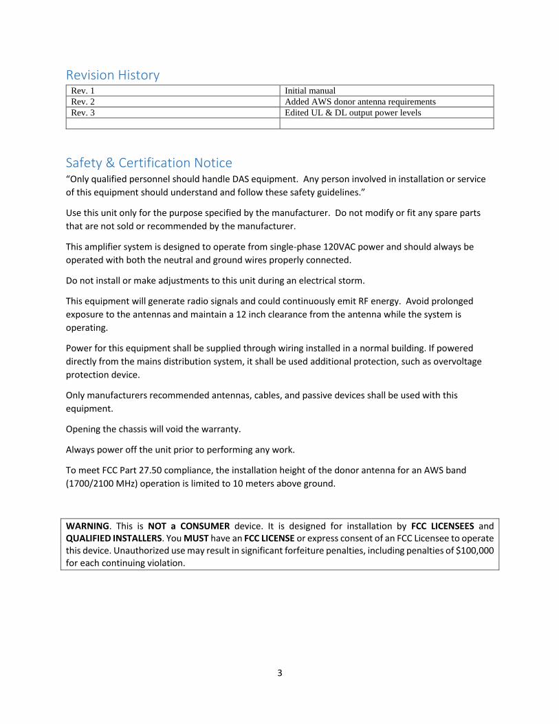
Revision History Rev. 1 Initial manual
Rev. 2 Added AWS donor antenna requirements
Rev. 3 Edited UL & DL output power levels
Safety & Certification Notice “Only qualified personnel should handle DAS equipment. Any person involved in installation or service
of this equipment should understand and follow these safety guidelines.”
Use this unit only for the purpose specified by the manufacturer. Do not modify or fit any spare parts
that are not sold or recommended by the manufacturer.
This amplifier system is designed to operate from single-phase 120VAC power and should always be
operated with both the neutral and ground wires properly connected.
Do not install or make adjustments to this unit during an electrical storm.
This equipment will generate radio signals and could continuously emit RF energy. Avoid prolonged
exposure to the antennas and maintain a 12 inch clearance from the antenna while the system is
operating.
Power for this equipment shall be supplied through wiring installed in a normal building. If powered
directly from the mains distribution system, it shall be used additional protection, such as overvoltage
protection device.
Only manufacturers recommended antennas, cables, and passive devices shall be used with this
equipment.
Opening the chassis will void the warranty.
Always power off the unit prior to performing any work.
To meet FCC Part 27.50 compliance, the installation height of the donor antenna for an AWS band
(1700/2100 MHz) operation is limited to 10 meters above ground.
WARNING. This is NOT a CONSUMER device. It is designed for installation by FCC LICENSEES and QUALIFIED INSTALLERS. You MUST have an FCC LICENSE or express consent of an FCC Licensee to operate this device. Unauthorized use may result in significant forfeiture penalties, including penalties of $100,000 for each continuing violation.
4
FCC Information FCC ID: 2AEQJ-CP4-001 WARNING. This is NOT a CONSUMER device. It is designed for installation by FCC LICENSEES and QUALIFIED INSTALLERS. You MUST have an FCC LICENSE or express consent of an FCC Licensee to operate this device. Unauthorized use may result in significant forfeiture penalties, including penalties in excess of $100,000 for each continuing violation. Warning: Changes or modifications to this device not expressly approved by the manufacturer could void the user’s authority to operate the equipment. You MUST operate this device with approved antennas and cables as specified by the manufacturer. Antennas MUST be installed at least 30 cm (12 inches) from any person.
Industry Canada Regulations IC ID: This Class B digital apparatus meets all requirements of the Canadian Interference Causing Equipment Regulations. Operation is subject to the following two conditions: (1) this device may not cause harmful interference, and (2) this device must accept any interference received, including interference that may cause undesired operation. The term “IC” before the radio certification number only signifies that Industry Canada technical specifications were met. RF Exposure: The manufacturer’s rated output power of this equipment is for single carrier operation. For situations when multiple carrier signals are present, the rating would have to be reduced by 3.5 dB, especially where the output is re-radiated and can cause interference to adjacent band users. This power reduction is to be by means of input power or gain reduction and not by an attenuator at the output of the device. Cet appareillage numérique de la classe [B] répond à toutes les exigences de l’interférence canadienne causant des règlements d’équipement. L’opération est sujette aux deux conditions suivantes: (1) ce diapositives peut ne pas causer l’interférence nocive, et (2) ce dispositif doit accepter n’importe quelle interférence reçue y compris l’interférence qui peut causer l’opération peu désirée. Le fabricant nominale de la puissance de sortie de ce matériel est simple transporteur. Pour les situations lorsque plusieurs signaux porteurs sont présents, l’évaluation devrait être réduite de 3.5 dB, en particulier lorsque le signal de sortie est réémise et peut provoquer des interférences adjacentes à la bande utilisateurs. Ce pouvoir est de la réduction par le biais de la sortie d’alimentation ou la réduction de gain et non par un atténuateur à la sortie du dispositif. Please note: This unit has been approved for use in Canada under RSS 131, however, consent for the use of this device to improve mobile communications coverage, must be obtained through your mobile network provider, prior to placing the unit in operation. Please refer to the Industry Canada document CPC 2-1-05, Section 6.1 available or viewable at: http://www.ic.gc.ca/epic/site/smt-gst.nsf/en/sf08942e.html
5
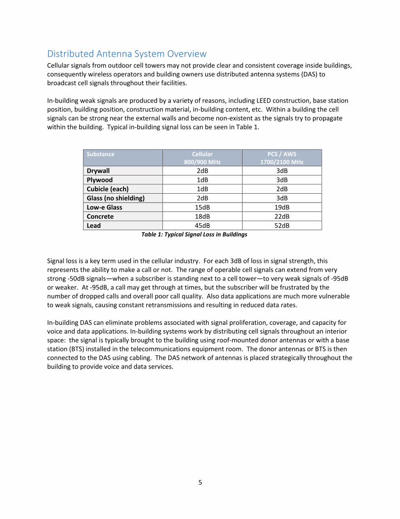
Distributed Antenna System Overview Cellular signals from outdoor cell towers may not provide clear and consistent coverage inside buildings, consequently wireless operators and building owners use distributed antenna systems (DAS) to broadcast cell signals throughout their facilities. In-building weak signals are produced by a variety of reasons, including LEED construction, base station position, building position, construction material, in-building content, etc. Within a building the cell signals can be strong near the external walls and become non-existent as the signals try to propagate within the building. Typical in-building signal loss can be seen in Table 1.
Substance
Cellular 800/900 MHz
PCS / AWS 1700/2100 MHz
Drywall 2dB 3dB
Plywood 1dB 3dB
Cubicle (each) 1dB 2dB
Glass (no shielding) 2dB 3dB
Low-e Glass 15dB 19dB
Concrete 18dB 22dB
Lead 45dB 52dB Table 1: Typical Signal Loss in Buildings
Signal loss is a key term used in the cellular industry. For each 3dB of loss in signal strength, this represents the ability to make a call or not. The range of operable cell signals can extend from very strong -50dB signals—when a subscriber is standing next to a cell tower—to very weak signals of -95dB or weaker. At -95dB, a call may get through at times, but the subscriber will be frustrated by the number of dropped calls and overall poor call quality. Also data applications are much more vulnerable to weak signals, causing constant retransmissions and resulting in reduced data rates. In-building DAS can eliminate problems associated with signal proliferation, coverage, and capacity for voice and data applications. In-building systems work by distributing cell signals throughout an interior space: the signal is typically brought to the building using roof-mounted donor antennas or with a base station (BTS) installed in the telecommunications equipment room. The donor antennas or BTS is then connected to the DAS using cabling. The DAS network of antennas is placed strategically throughout the building to provide voice and data services.

6
Product Description The CP4 Coverage Node (CP4) is designed to provide 2G, 3G & 4G communications within a building
covering 5,000 square feet of coverage at each location supporting an Omni or directional antenna. The
product provides reliable cellular communications within all types of in-building environments. The
major features include high speed data services, low power operation, alarm triggers, remote access and
status reporting.
The CP4 is part of the Intelligent Distributed Amplifier System (IDAS) family of products and supports
Cellular, PCS, LTE and AWS commercial cellular communications as well as public safety radio
communications. The IDAS works with multiple coverage nodes strategically placed within the building
to provide reliable texting, data, and voice communications. All coverage nodes in the system are
networked together to deliver a balanced and reliable signal throughout the facility. The head end unit
manages all of the amplifiers in a system along with local and remote access for monitoring and status
checking.
Automatic Shutdown The detected power levels are monitored by a microcontroller in the CP4. The microcontroller limits the
maximum output power to keep the amplifiers linear without interfering with the network power
control. The CP4 will also detect low-level self-oscillation and corrects it in real-time. During installation
the CP4 alerts the user with LED outputs to adjust the position of the antennas if the unit is self-
oscillating to clear the issue. If the microcontroller cannot correct the self-oscillation it will shut the unit
down to protect the network and notify the user with LED outputs on the unit.
To resolve oscillation, increase the antenna separation between in-building antennas or provide improved isolation from the outside donor antennas and the in-building antennas. This isolation should be in the order of 70 dB and is usually obtained by mounting the outside antenna away from the edges of the roof. The use of window mounts or other non-rooftop mountings should be avoided.
Authorized Equipment The CP4 has been tested using the antennas and cable.
Part Number Description
WOA-N11 In-building broadband ceiling mount antenna
WDA-N21 In-building broadband directional wall mount antenna
WDA-N03 Wideband directional donor antenna
CC10-001 10 ft. antenna cable
Warning: do not use any antennas, cables, and /or coupling devices not
authorized by the manufacturer.

7
Product Specifications The product works in conjunction with the head-end as well as surrounding coverage nodes, and is responsible for delivering optimal cellular communications to the target coverage area. The CP4 supports the following:
PCS Band 2: System gain: uplink = 60dB; downlink = 60dB Downlink: 1.93-1.99GHz, Uplink: 1.85-1.91GHz
AWS Band 4: System gain: uplink = 60dB; downlink = 60dB Downlink: 2.11-2.155GHz, Uplink: 1.71-1.755GHz
Cellular Band 5: System gain: uplink = 60dB; downlink = 60dB Downlink: 869-894MHz, Uplink: 824-849MHz
LTE Band 13: System gain: uplink = 60dB; downlink = 60dB Downlink: 746-757MHz, Uplink: 776-787MHz
LTE Band 17: System gain: uplink = 60dB; downlink = 60dB Downlink: 734-746MHz, Uplink: 704-716MHz
General Product: Industrial enclosure Input power = 5.0 VDC Dimensions 5.25” x 7.75” x 2”
8
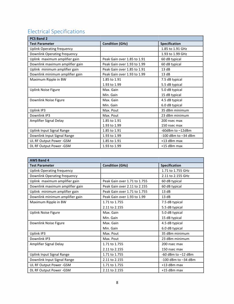
Electrical Specifications PCS Band 2
Test Parameter Condition (GHz) Specification
Uplink Operating frequency 1.85 to 1.91 GHz
Downlink Operating frequency 1.93 to 1.99 GHz
Uplink maximum amplifier gain Peak Gain over 1.85 to 1.91 60 dB typical
Downlink maximum amplifier gain Peak Gain over 1.93 to 1.99 60 dB typical
Uplink minimum amplifier gain Peak Gain over 1.85 to 1.91 13 dB
Downlink minimum amplifier gain Peak Gain over 1.93 to 1.99 13 dB
Maximum Ripple in BW 1.85 to 1.91 7.5 dB typical
1.93 to 1.99 5.5 dB typical
Uplink Noise Figure Max. Gain 5.0 dB typical
Min. Gain 15 dB typical
Downlink Noise Figure Max. Gain 4.5 dB typical
Min. Gain 6.0 dB typical
Uplink IP3 Max. Pout 35 dBm minimum
Downlink IP3 Max. Pout 23 dBm minimum
Amplifier Signal Delay 1.85 to 1.91 200 nsec max
1.93 to 1.99 150 nsec max
Uplink Input Signal Range 1.85 to 1.91 -60dBm to –12dBm
Downlink Input Signal Range 1.93 to 1.99 -100 dBm to –34 dBm
UL RF Output Power -GSM 1.85 to 1.91 +13 dBm max
DL RF Output Power -GSM 1.93 to 1.99 +15 dBm max
AWS Band 4
Test Parameter Condition (GHz) Specification
Uplink Operating frequency 1.71 to 1.755 GHz
Downlink Operating frequency 2.11 to 2.155 GHz
Uplink maximum amplifier gain Peak Gain over 1.71 to 1.755 60 dB typical
Downlink maximum amplifier gain Peak Gain over 2.11 to 2.155 60 dB typical
Uplink minimum amplifier gain Peak Gain over 1.71 to 1.755 13 dB
Downlink minimum amplifier gain Peak Gain over 1.93 to 1.99 13 dB
Maximum Ripple in BW 1.71 to 1.755 7.5 dB typical
2.11 to 2.155 5.5 dB typical
Uplink Noise Figure Max. Gain 5.0 dB typical
Min. Gain 15 dB typical
Downlink Noise Figure Max. Gain 4.5 dB typical
Min. Gain 6.0 dB typical
Uplink IP3 Max. Pout 35 dBm minimum
Downlink IP3 Max. Pout 23 dBm minimum
Amplifier Signal Delay 1.71 to 1.755 200 nsec max
2.11 to 2.155 150 nsec max
Uplink Input Signal Range 1.71 to 1.755 -60 dBm to –12 dBm
Downlink Input Signal Range 2.11 to 2.155 -100 dBm to –34 dBm
UL RF Output Power -GSM 1.71 to 1.755 +13 dBm max
DL RF Output Power -GSM 2.11 to 2.155 +15 dBm max
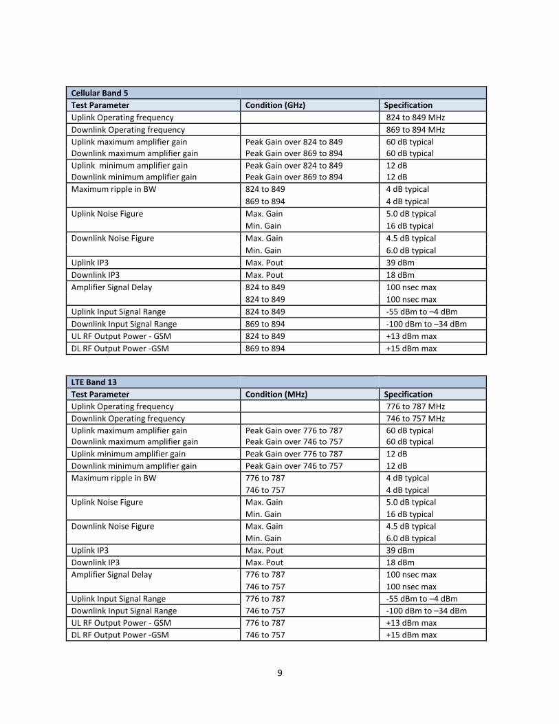
9
Cellular Band 5
Test Parameter Condition (GHz) Specification
Uplink Operating frequency 824 to 849 MHz
Downlink Operating frequency 869 to 894 MHz
Uplink maximum amplifier gain Peak Gain over 824 to 849 60 dB typical
Downlink maximum amplifier gain Peak Gain over 869 to 894 60 dB typical
Uplink minimum amplifier gain Peak Gain over 824 to 849 12 dB
Downlink minimum amplifier gain Peak Gain over 869 to 894 12 dB
Maximum ripple in BW 824 to 849 4 dB typical
869 to 894 4 dB typical
Uplink Noise Figure Max. Gain 5.0 dB typical
Min. Gain 16 dB typical
Downlink Noise Figure Max. Gain 4.5 dB typical
Min. Gain 6.0 dB typical
Uplink IP3 Max. Pout 39 dBm
Downlink IP3 Max. Pout 18 dBm
Amplifier Signal Delay 824 to 849 100 nsec max
824 to 849 100 nsec max
Uplink Input Signal Range 824 to 849 -55 dBm to –4 dBm
Downlink Input Signal Range 869 to 894 -100 dBm to –34 dBm
UL RF Output Power - GSM 824 to 849 +13 dBm max
DL RF Output Power -GSM 869 to 894 +15 dBm max
LTE Band 13
Test Parameter Condition (MHz) Specification
Uplink Operating frequency 776 to 787 MHz
Downlink Operating frequency 746 to 757 MHz
Uplink maximum amplifier gain Peak Gain over 776 to 787 60 dB typical Downlink maximum amplifier gain Peak Gain over 746 to 757 60 dB typical
Uplink minimum amplifier gain Peak Gain over 776 to 787 12 dB
Downlink minimum amplifier gain Peak Gain over 746 to 757 12 dB
Maximum ripple in BW 776 to 787 4 dB typical
746 to 757 4 dB typical
Uplink Noise Figure Max. Gain 5.0 dB typical
Min. Gain 16 dB typical
Downlink Noise Figure Max. Gain 4.5 dB typical
Min. Gain 6.0 dB typical
Uplink IP3 Max. Pout 39 dBm
Downlink IP3 Max. Pout 18 dBm
Amplifier Signal Delay 776 to 787 100 nsec max
746 to 757 100 nsec max
Uplink Input Signal Range 776 to 787 -55 dBm to –4 dBm
Downlink Input Signal Range 746 to 757 -100 dBm to –34 dBm
UL RF Output Power - GSM 776 to 787 +13 dBm max
DL RF Output Power -GSM 746 to 757 +15 dBm max

10
LTE Band 17
Test Parameter Condition (MHz) Specification
Uplink Operating frequency 704 to 716 MHz
Downlink Operating frequency 734 to 746 MHz
Uplink maximum amplifier gain Peak Gain over 704 to 716 60 dB typical
Downlink maximum amplifier gain Peak Gain over 734 to 746 60 dB typical
Uplink minimum amplifier gain Peak Gain over 704 to 716 12 dB
Downlink minimum amplifier gain Peak Gain over 734 to 746 12 dB
Maximum ripple in BW 704 to 716 4 dB typical
734 to 746 4 dB typical
Uplink Noise Figure Max. Gain 5.0 dB typical
Min. Gain 16 dB typical
Downlink Noise Figure Max. Gain 4.5 dB typical
Min. Gain 6.0 dB typical
Uplink IP3 Max. Pout 39 dBm
Downlink IP3 Max. Pout 18 dBm
Amplifier Signal Delay 704 to 716 100 nsec max
734 to 746 100 nsec max
Uplink Input Signal Range 704 to 716 -55 dBm to –4 dBm
Downlink Input Signal Range 734 to 746 -100 dBm to –34 dBm
UL RF Output Power - GSM 704 to 716 +13 dBm max
DL RF Output Power -GSM 734 to 746 +15 dBm max
Pre-installation Survey A pre-installation survey should be performed prior to commitment to installation. Measurement of Received Signal Strength Indication (RSSI) should be recorded throughout the building in all areas where mobile broadband coverage is desired. RSSI levels around the exterior of the building as well as on the rooftop or as close to the point where the exterior antenna will be installed should also be recorded. RSSI readings at the position where the outside antenna will be installed should be greater than –90 dBm. Successful installations may be made with lower readings and engineering support will be required.
The exact location of the proposed outside antenna should be measured with a GPS unit and the coordinates of the cell sites closest to the building in which the system is being installed should be obtained. With these coordinates the distance and bearing to each of the local cell sites can be computed and made available to the installation team. The first choice should be the closest site unless there is blockage in the form of buildings or terrain between the building and this cell site. If blockage exists an alternate site may be available. If GPS coordinates are not available there is an alternative method of locating the dominant site: connect a handset via SMA female to N male adapter to the directional donor antenna. Rotate the antenna until maximum RSSI readings are obtained and secure it. The location of the CP4 and the interior antennas should be determined through the use of floor plans of the building in which the system is to be installed. It is important to locate the CP4 as close as possible to the antenna to keep the coax runs as short as possible. A maximum length of 150 feet is suggested from the riser tap to the CP4

11
although longer runs might be accommodated. This assumes that a coax with loss at 1900 MHz of approximately 8.0 dB per 100 feet is used. The coax used should be a nominal RG-11 type with a flame retardant rating except when installed in space where moving air (heating and/or cooling) exists. In which case the coax must be “plenum” rated. Of primary concern is the isolation between the outside antenna and the inside antennas.
Physical Installation You must obtain express consent of an FCC Licensee prior to the installation of an industrial signal booster. A contact list of each licensee is provided in this manual. The coaxial cable discussed above should be pulled from the rooftop location to the space designated
for the head-end installation. To meet FCC Part 27.50 compliance, the installation height of the donor
antenna for an AWS band (1700/2100 MHz) operation is limited to 10 meters above ground. Additional
coax should be pulled from the head-end to where power splitters are located and thus to the position
designated for each CP4 and associated antennas. Usually this is accomplished by using existing
cableways and running the cable above suspended ceilings. In many cases the Omni-directional
antennas can be located above the suspended ceilings however, when this is not possible, alternatives
such as ceiling or wall mounted antennas may be used.
When mounting the CP4, take care to avoid areas of high heat or extreme cold. In general, do not place the unit on or near the top of high ceilings, by heaters or in cold storage areas. The CP4 provides the following visual diagnostics using the two LED lights.
Top LED power status
Power feed is good.
Power level is low. Need to check connections.
Power level is not adequate. Check power source as well as connections.
Bottom LED RF status
RF feed is good.
RF signal level is low. Need to check connections.
RF signal level is not adequate. Check RF source as well as connections.
Not connected to head-end when blinking red LED. Check status of head-end and all connections, cable, and components.
Unit is self-oscillating and the coverage antenna needs to be installed at least 6 feet away for the unit.

12
Contact Information To consult with a Whoop Wireless directly please call us at (888) 983-7381 or email at [email protected].
Licensee Contact Information
For further information, visit http://wireless2.fcc.gov/UlsApp/UlsSearch/searchLicense.jsp Verizon Verizon Wireless (VAW) LLC Attn: Regulatory 1120 Sanctuary Pkwy, #150 Alpharetta, GA 30009-7630 (770) 797-1070 [email protected] AT&T AT&T Mobility Wireless 3300 E. Renner Road, # B3132 Richardson, TX 75082 [email protected] T-Mobile T-Mobile License LLC 12920 SE 38th St Bellevue, WA 98006 (425) 383-4000 [email protected] Sprint SPRINTCOM, INC. 12502 Sunrise Valley Drive Reston, VA 20196