cp-3800 gc getting started manual - seta electron
TRANSCRIPT

©Varian, Inc. 1999 Printed in U.S.A. 03-914647-00:Rev. 41
CP-3800 GCGetting Started Manual
Getting Started � Installation � Basic OperationMaintenance � Parts and Supplies
Varian Analytical Instruments2700 Mitchell DriveWalnut Creek, CA 94598-1675/usa

Read Before OperatingImportant Safeguards
CAUTIO N
The following items are frequently not recognized or are overlooked by new users whilelearning to operate a Gas Chromatograph. They are brought to your attention to safeguardagainst damage to your equipment.
• Carrier gas must be flowing through the column before heating the column oven.Carefully evaluate columns that have been heated with no carrier gas flowing throughand discard, if damaged. Ensure the injector contains a septum and there is a positiveflow of carrier gas before heating the column.
• Become familiar with the location and identity of injector and detector options prior tomaking settings at the GC keyboard and pneumatics panel. For example, determine thephysical location of the injector you want to use (front, middle, or rear) and identify thespecific pneumatic controls associated with it (manual pneumatics or Electronic FlowControl). Similarly, determine the physical location of the detector you want to use andidentify the specific pneumatic controls for this detector.
• Heating an ECD to elevated temperatures without carrier or make-up gas flowing throughit can damage the ECD cell. This can happen inadvertently especially when the ECD isnot in use. For this reason, it is recommended that a low flow of carrier or make-up gasbe maintained through an ECD at all times.
• If your system has a TCD, gas must be flowing through both channels to protect thefilaments. Turn power to filaments off when not in use.
Important Tips Regarding 3800 Operation• After editing the active method, it must be re-activated before running the next analysis.
Always remember to activate a method after you have made edits, if you intend to run thatmethod next.
• Note that the GC control keys allow access to both the active method status (top of thedisplay) and the current method available to edit (middle of the display). If you want toedit the active method then you must make it the current edit method. Both the currentactive method and edit method are listed on the top line of the 3800 display.
• If a potentially hazardous fault is detected, such as a thermal runaway, the 3800 shutsdown the affected component and reports the fault. After correcting the fault, normaloperation is restored by powering the 3800 OFF then ON.

CP-3800 GC Getting Started Manual 1
Table of Contents
INTRODUCTION .......................................................................................................................5Guide to the 3800 User Manuals............................................................................................5
Finding Information in these Manuals.................................................................................5Abbreviations......................................................................................................................5
Brief Description of the 3800 Gas Chromatograph ................................................................6Configuration and Options......................................................................................................7
INSTALLATION................................................................................................................... ......9Site Requirements for GC Installation....................................................................................9
Power Requirements ..........................................................................................................9Space Requirements ........................................................................................................10Environmental Requirements ...........................................................................................10Peripheral Connectors......................................................................................................11
GC Installation......................................................................................................................12Inspection .........................................................................................................................12Unpacking.........................................................................................................................12Remove Protective Devices .............................................................................................12Connect Data Handling Peripherals .................................................................................12Select Gases ....................................................................................................................13Install Gas Regulators and Set Pressures........................................................................13Connect Gases.................................................................................................................13Connect GC to Power.......................................................................................................14Turn Power On .................................................................................................................14Factory Default States and Settings .................................................................................14
Quick Guide to the 3800 Keyboard and Display ..................................................................15Getting Around the Keyboard ...........................................................................................15
Column Installation and Conditioning...................................................................................29Connect Column to Injector ..............................................................................................29Nuts and Ferrules for Capillary Columns..........................................................................29Connect Capillary Column to Injector ...............................................................................31Nuts and Ferrules for Packed Columns ...........................................................................32Connect a Packed Column to the Injector........................................................................32Varian Test Column..........................................................................................................33Identify Carrier Gas Controls and Turn on Flow...............................................................331079 Split Vent Flow and Septum Purge Flow .................................................................34Set Carrier Gas Flow Rate to Condition Column..............................................................35Note for Capillary Column Users ......................................................................................35Conditioning the Injector and Column ..............................................................................35Connect Capillary Column to Detector .............................................................................36Column Insertion Depths for Varian Detectors.................................................................37Connect Metal Packed Column to Detector .....................................................................38Check for Leaks ...............................................................................................................38
2 03-914647-00:4
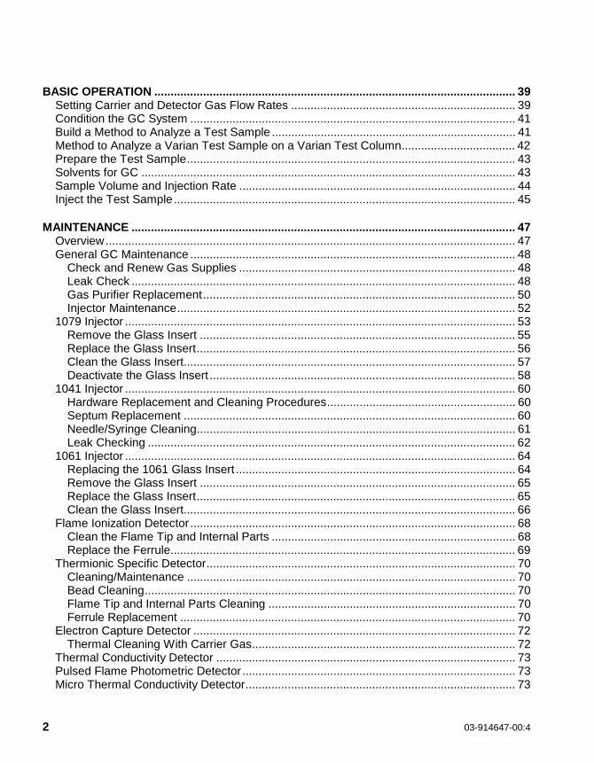
BASIC OPERATION ............................................................................................................... 39Setting Carrier and Detector Gas Flow Rates ..................................................................... 39Condition the GC System .................................................................................................... 41Build a Method to Analyze a Test Sample ........................................................................... 41Method to Analyze a Varian Test Sample on a Varian Test Column................................... 42Prepare the Test Sample..................................................................................................... 43Solvents for GC ................................................................................................................... 43Sample Volume and Injection Rate ..................................................................................... 44Inject the Test Sample......................................................................................................... 45
MAINTENANCE ...................................................................................................................... 47Overview.............................................................................................................................. 47General GC Maintenance .................................................................................................... 48
Check and Renew Gas Supplies ..................................................................................... 48Leak Check ...................................................................................................................... 48Gas Purifier Replacement................................................................................................ 50Injector Maintenance........................................................................................................ 52
1079 Injector ........................................................................................................................ 53Remove the Glass Insert ................................................................................................. 55Replace the Glass Insert.................................................................................................. 56Clean the Glass Insert...................................................................................................... 57Deactivate the Glass Insert .............................................................................................. 58
1041 Injector ........................................................................................................................ 60Hardware Replacement and Cleaning Procedures.......................................................... 60Septum Replacement ...................................................................................................... 60Needle/Syringe Cleaning.................................................................................................. 61Leak Checking ................................................................................................................. 62
1061 Injector ........................................................................................................................ 64Replacing the 1061 Glass Insert ...................................................................................... 64Remove the Glass Insert ................................................................................................. 65Replace the Glass Insert.................................................................................................. 65Clean the Glass Insert...................................................................................................... 66
Flame Ionization Detector .................................................................................................... 68Clean the Flame Tip and Internal Parts ........................................................................... 68Replace the Ferrule.......................................................................................................... 69
Thermionic Specific Detector............................................................................................... 70Cleaning/Maintenance ..................................................................................................... 70Bead Cleaning.................................................................................................................. 70Flame Tip and Internal Parts Cleaning ............................................................................ 70Ferrule Replacement ....................................................................................................... 70
Electron Capture Detector ................................................................................................... 72Thermal Cleaning With Carrier Gas................................................................................. 72
Thermal Conductivity Detector ............................................................................................ 73Pulsed Flame Photometric Detector .................................................................................... 73Micro Thermal Conductivity Detector................................................................................... 73

CP-3800 GC Getting Started Manual 3
PARTS AND SUPPLIES..........................................................................................................75To Order Parts and Supplies … .......................................................................................75
Injectors................................................................................................................................751079 Injector.....................................................................................................................751041/1061 Injector............................................................................................................76
Detectors ..............................................................................................................................76Flame Ionization Detector.................................................................................................76Thermionic Specific Detector ...........................................................................................76Electron Capture Detector ................................................................................................76Thermal Conductivity Detector .........................................................................................77Pulsed Flame Photometric Detector.................................................................................77Micro-TCD ........................................................................................................................77
Figure 1 Connectors for Peripheral Equipment........................................................................11Figure 2 3800 GC Keyboard ....................................................................................................15Figure 3 1079 Injector - Cross-Sectional View.........................................................................54Figure 4 1041 Injector Assembly..............................................................................................61Figure 5 1061 Injector Assembly..............................................................................................64Figure 6 Flame Ionization Detector Assembly .........................................................................69Figure 7 Thermionic Specific Detector Assembly ....................................................................71
Table 1 Physical Dimensions of the 3800 GC System Components .......................................10Table 2 Flow Rates for Carrier and Detector Gases for the 3800 Gas Chromatograph..........39
CP-3800 GC Getting Started Manual 5
Introduction
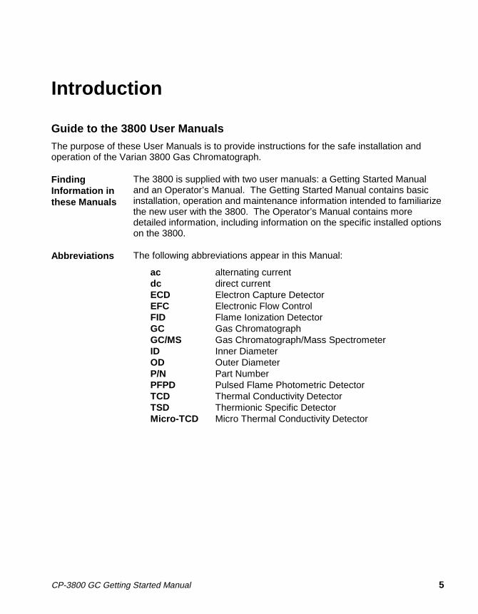
Guide to the 3800 User Manuals
The purpose of these User Manuals is to provide instructions for the safe installation andoperation of the Varian 3800 Gas Chromatograph.
FindingInformation inthese Manuals
The 3800 is supplied with two user manuals: a Getting Started Manualand an Operator’s Manual. The Getting Started Manual contains basicinstallation, operation and maintenance information intended to familiarizethe new user with the 3800. The Operator’s Manual contains moredetailed information, including information on the specific installed optionson the 3800.
Abbreviations The following abbreviations appear in this Manual:
ac alternating currentdc direct currentECD Electron Capture DetectorEFC Electronic Flow ControlFID Flame Ionization DetectorGC Gas ChromatographGC/MS Gas Chromatograph/Mass SpectrometerID Inner DiameterOD Outer DiameterP/N Part NumberPFPD Pulsed Flame Photometric DetectorTCD Thermal Conductivity DetectorTSD Thermionic Specific DetectorMicro-TCD Micro Thermal Conductivity Detector

6 03-914647-00:4
Brief Description of the 3800 Gas Chromatograph
The following are some of the key features of the 3800:
• Three injectors, columns and detectors can be installed and operatedsimultaneously.
• The 1079 Universal Capillary Injector provides five modes of injection -isothermal split and splitless, temperature ramped splitless, on-columnand large volume.
• Electronic or manual control of carrier gas.
• Ethernet® communications with full networking capability.
• A full suite of universal and selective detectors - FID, TCD, ECD, TSD(N, P), PFPD (S, P, N, C, Metals), Micro-TCD and Ion Trap MS.
• Large, swing-out pneumatics for easy access.
• Seven heated zones and seven external events for maximum flexibilityand custom configurations.
• Up to eight separately programmed and stored analytical methods.
• Intuitive, function-based keyboard with large, dot matrix display for easeof use in method building and viewing instrument status.
• Built-in Custom Solutions capability - valved systems, custom plumbing,six-position valve oven, methanizer.
• Large column oven for easy access and installation of up to threeanalytical columns.
• A complete range of GC automation and sample preparation techniques -the 8200 AutoSampler with AutoDrive accessory, dual 8200AutoSamplers, Solid Phase MicroExtraction, Purge and Trap, HeatedHeadspace, and the Archon Purge and Trap AutoSampler.

CP-3800 GC Getting Started Manual 7
Configuration and Options
The 3800 has seven heated zones, one of which is always configured as the columnoven. The following options may be configured in the other six available heatedzones:
• 1079 Universal Capillary Injector
• 1041 On-Column Injector for large bore (0.53 mm ID) or packed columns
• 1061 Flash Vaporization Injector for large bore or packed columns
• Single, dual, or multi-position Valve Oven
• Flame Ionization Detector
• Thermal Conductivity Detector
• Electron Capture Detector
• Thermionic Specific Detector
• Pulsed Flame Photometric Detector
• Methanizer
• Micro Thermal Conductivity Detector
Any combination of three injectors may be installed on the 3800. If a valve oven isinstalled, it normally replaces two injector positions.
Any combination of three detectors can be installed with the following exceptions:Only two TCD or PFPD detectors can be installed. If two standard TCDs areinstalled, then no other detectors can be accommodated. However, a dual TCD (twocells in one housing) is available as a Custom Solution which allows installation ofanother detector, such as an FID, behind it.
The methanizer typically occupies the same location as one of the detectors. Dual8200 AutoSamplers restrict the 3800 configuration to two injectors and two detectors.
Installed options on the 3800 are generally identified by their location. The optionsmounted on the top of the instrument, such as those listed above, are designated asFront, Middle and Rear to coincide with their relative location or the location of theirrespective electronic control modules.

CP-3800 GC Getting Started Manual 9
Installation
Site Requirements for GC Installation
PowerRequirements
Power SourceEach 3800 GC requires a separate circuit with the followingcharacteristics:
101 Vac ± 10%, 50 or 60 Hz ± 2%, 25 Amps, 2.5 Kilowatts
120 Vac ± 10%, 60 Hz ± 2%, 20 Amps, 2.4 Kilowatts
230 Vac ± 15%, 50 Hz ± 2%, 10 Amps, 2.3 Kilowatts
Installation Category: II
Ground
It is essential to have a safety ground connection to this instrument.
Power Cord
In Europe the instrument will be supplied with an IEC 320 style socket.The power cord assembly can be changed to suit your local power andsocket requirements. In the United States and Japan the instrument isequipped with a fixed power cord and plug.
Heat DissipationCalculate heat dissipation using the following formula:
Watts x 3.4129 = BTU/hr.
Actual dissipation will depend on method parameters and instrumentconfiguration.
CAUT IO NHeat from the column oven is vented through the rear of the GC. Makecertain that the hot column oven exhaust is not directed onto otherelectronic instruments, cables or gas lines.
Fuses
There are four fuses accessible on the top of the 3800:
F1: 6.3A T, F2: 6.3A T, F3: 10.0A F, F4: 6.3A T

10 03-914647-00:4
SpaceRequirements
Allow sufficient bench space to permit installation of workstations,integrators, autosamplers and other peripheral GC equipment. The tablebelow lists the physical dimensions and weight of the GC and theperipheral instruments which may be installed near it. Allow six inches ofspace at the sides and rear of the GC to permit free air circulation.
The power cord, gas inlets and the optional Ethernet® communicationsport are located on the rear panel of the instrument. The power switch is tothe rear of the top cover. Signal output connectors for peripheralinstrumentation such as autosamplers and integrators are located underthe left top cover of the instrument.
Table 1 Physical Dimensions of the 3800 GC System Components
Height Width Depth Weight
Instrument in. cm in. cm in. cm lb. kg3800 GC 20 51 26 66 22 56 95 438200 AutoSampler 20 51 6 16 16 41 24 11Tekmar 3000 Purge and Trap 19 48 9 23 18 46 37 16.8Archon Purge and Trap AutoSampler 17 43 21.5 55 21 53 80 36Tekmar ALS-2016 27 69 15 38 15 38 35 13.1Genesis Headspace AutoSampler 22 56 28 72 18 46 110 50Star Chromatography Workstation(computer with monitor, approximatevalues)
17 43 17 43 21 53 35 16
Environmental Requirements Pollution degree: 2
Humidity: 5% to 95% RH
Temperature: 10° to 40°C operating, -20° to 65°Cnon-operating
The 3800 Gas Chromatograph is intended for indooruse and certified for operation up to an altitude of2000m, however, the 3800 is designed for use at higheraltitudes. Varian GCs should be protected fromcorrosive chemicals or gases, dust/ particulateaccumulation, and direct venting of air conditioners,heaters, furnaces or fans.

INSTALLATIONSite Requirements for GC Installation
CP-3800 GC Getting Started Manual 11
PeripheralConnectors
The 3800 Gas Chromatograph is equipped with various connectors on therear panel and top of the instrument intended for use with peripheralequipment such as autosamplers and data handling devices. The followingare the standard connectors on the 3800 and their intended uses:
Rear Panel Ethernet® Connector: BNC connector for 10 base 2 cable.Printer Connector: 25 pin “D” connector, intended for future useAC Power Input: 230V units only.
Top of Instrument (under detector cover)
J4
Sample Introduction Device1, 25 pin “D” connector,typically used forautosampler control.
J5
Sample Introduction Device2, 25 pin “D” connector,typically used forautosampler control.
J6
Analog Out, for connection todata handling devices thathandle analog signals suchas integrators, 15 pin “D”connector.
J45 and J46
Aux Output,intended forfuture use.
Figure 1 Connectors for Peripheral Equipment

12 03-914647-00:4
GC Installation
Inspection The 3800 Gas Chromatograph will arrive packed in one large palletized boxand one or more smaller cartons. Inspect the cartons carefully for damageor signs of rough handling. Report damage to the carrier and to your localVarian office.
Unpacking Unpack the GC and accessories carefully and transfer to the work area,using proper handling techniques. The GC should be lifted from the bottom.Inspect the GC and accessories and immediately report any damage to thecarrier and your local Varian office.
WARNINGAvoid back strain or injury by followingall safety precautions when lifting heavyobjects.
RemoveProtectiveDevices
The instrument has been protected during shipment by various caps, plugsand restraints. Prior to operating, remove:
• Shipping dowel for oven fan motor from hole in GC rear panel
• Detector tower plugs under detector cover
• Gas bulkhead fitting plugs on rear panel
• Any plastic plugs inside the column oven
Connect DataHandlingPeripherals
Workstations, integrators and other data handling devices are connected tothe cable connectors on the back panel or the top of the instrument.
• If the Varian Star Chromatography Workstation with 3800 control is beinginstalled follow the installation instructions in the communications sectionof the 3800 Operator’s manual. This installation simply involves making aconnection to the Ethernet® connector on the rear panel of the GC.Additional information on 3800 Workstation control is provided in the StarWorkstation documentation.
• If an analog output signal is being used, follow the specific installationinstructions provided with the analog interface kit.

INSTALLAT IONGC Installation
CP-3800 GC Getting Started Manual 13
Select Gases The following gases are commonly used in Gas Chromatography for thefollowing functions. Note that the recommended purity for carrier make-upand detector fuel gases is 99.999%. In addition, the use of gas filters toremove hydrocarbons, oxygen, and water from carrier gases isrecommended.
Gas FunctionHe, N2, H2, Ar, Ar/CH4 Carrier gasH2, Air Detector fuel gasesHe, N2, Ar/CH4 Make-up gas for capillary column useAir AutoSampler operationLN2, LCO2 Cryogenics
Install GasRegulatorsand SetPressures
Carrier gas, air and H2 supplied from cylinders or manifolds should have atwo-stage regulator having a zero to 100 psi low-pressure stage. Setcylinder regulator pressure to match the GC gas inlet pressures, listedbelow:
Gas Inlet PressureCarrier gas 80 psiMake-up 80 psiAir 60 psiH2 40 psi
ConnectGases
Follow the steps below to connect gas supplies to your 3800 GC:
1 Cut required lengths of heat-cleaned 1/8″ copper tubing for thecarrier and fuel gas plumbing. Clean the ends of the tubing with ametal file.
2 Slide a 1/8″ Swagelok nut, back ferrule, and front ferrule over oneend of the copper tubing and attach to the outlet fitting on thecylinder regulator.
3 Push the copper tubing into the outlet fitting as far as it will go, thenpull back very slightly and tighten 3/4-turn past finger-tight with a7/16″ wrench.
4 Slide a 1/8″ Swagelok nut, back ferrule, and front ferrule over theother end of the copper tubing and connect it to the correspondinggas inlet on the GC rear panel.

14 03-914647-00:4
5 Push the copper tubing into the bulkhead fitting as far as it will go,then pull back very slightly and tighten 3/4-turn past finger-tight witha 7/16" wrench.
6 Make sure the gas supply control valve, which controls gas pressureto the GC, is completely closed. Open this valve slowly and monitorthe pressure gauges on the dual stage regulator. The first pressuregauge should now read the pressure of the cylinder.
7 Cautiously turn the regulator valve to supply gas to the GC. Watchthe pressure gauge closely and adjust the pressure according to thetable above.
8 Leak check all fittings.
Connect GCto Power
Plug the GC power cord into an appropriate source of power. For site powerrequirements, refer to page 9.
Turn PowerOn
Turn on the GC power switch located at the top left of the GC.
• The GC display should illuminate after a few moments and go throughan initialization sequence.
• The 3800 automatically enters the INSTRUMENT STATUS screen onpower up. Press the SETUP key and select view SETUP to verify the3800 configuration.
FactoryDefault Statesand Settings
Your GC is shipped from the factory with default settings. The following isrelevant information on the factory default states and settings:
• When the GC is turned on, all installed heated zones except for thecolumn oven default to power OFF.
• The default active method is method 1. The column oven defaults topower ON and a set temperature of 50°C.
• When installed components that use a heated zone are turned ON in theactive method, they default to a set temperature of 50°C.
CylinderRegulator
1/8" Copper Tubing
Swagelok Nut
Back Ferrule
Front Ferrule

INSTALLATIONQuick Guide to the 3800 Keyboard and Display
CP-3800 GC Getting Started Manual 15
Quick Guide to the 3800 Keyboard and Display
GettingAround theKeyboard
The 3800 user interface is designed for maximum ease of use. The keyboardis laid out in functional sections allowing quick access to the necessaryinformation. This subsection of the manual gives a brief overview of thefunctionality associated with each section of the keyboard. For more detailedinformation refer to the Operator’s Manual: Section 1, The 3800 Keyboard andDisplay.
ACT IVEM ETHO D
E DITM ETH O D CTRL
ENDTIME
RUNT IM E
ENTRY
TABLE EDIT
PAG E CURSOR
NE WLINE
H ELP UND O
DELE TELINE
CLEARTA BLE
ENT E RDEC RIN CR
SAM PLEDE LIVE RY INJE CTO R
G C CONTROL IN STRUMENTFLO W /
P RESSU RE
CO LUM NO VE N DE TECTO R OU TPUT
ME THOD SEQ UENC ESELEC T /
EDIT
PRIO RIT Y SA M PLE
METHOD
AUTOMATION
AC TIVATE
SING LE M ETH OD
ED IT ME NU
N OTRE ADY RE A DY RUN
START STOP
STATU S SETU P
M ENU
7 8 9
4 5 6
1 2 3
0 .
+
SUS PEND R ESUM E
Figure 2 3800 GC Keyboard
PAGE CURSOR The PAGE and CURSOR keys are used to navigate around the3800 display and move between screens. Pressing the PAGE UParrow key backs up to the previous page; pressing the PAGEDOWN arrow key advances to the next page. The cursor arrowkeys move the screen cursor from one field to another.
To select a menu item, the cursor can be placed on the item and the ENTERkey pressed or if the menu item has a number, the same menu item can beselected by pressing the appropriate number followed by the ENTER key.
Because the pertinent information cannot always fit on one screen, multiplepages are sometimes used. Where multiple pages are used this is alwaysindicated on the title line of the display, e.g., Column Oven, Page 1of 2.

16 03-914647-00:4
TABLE EDITNEWLIN E
D ELETELIN E
CLEARTABLE
If you are modifying a table such as a temperature ramp table ortimed events table, the TABLE EDIT keys can be used to add newlines to the table, delete the highlighted line from the table, or clearthe table of all entries except for initial default conditions.
ENTRYHELP UND O
ENTE RD ECRINCR
7 8 9
4 5 6
1 2 3
0 .
+
The ENTRY section of the keyboard contains the numeric keys (0 -9, decimal point, minus sign, and infinity), the increment (INCR) anddecrement (DECR) keys, the ENTER key, the HELP key, and theUNDO key. The INCR and DECR keys can be used to select froma range of values for a discrete parameter or used to increment ordecrement a numeric parameter. Pressing the UNDO key will undothe last editing action. The ENTER key either advances the cursorto the next parameter if the value in the current field is not updatedor updates the parameter value if a new value is entered. In thelatter case the ENTER key must be pressed again to advance to thenext parameter. A more convenient way to enter parameters is touse the cursor keys to move from one field to another after aparameter value has been changed.
Pressing the HELP key gives you a context sensitive explanation for theparameter at the cursor location.
INSTRUMENT
STATUS SETUP
M E NU
The INSTRUMENT and GC CONTROL sections are mostcommonly accessed. The INSTRUMENT section is where the3800 is configured in terms of installed options and allowableoperating parameters, and where an overview of instrument statuscan be viewed. The configuration information is accessed usingthe SETUP key and the instrument status information is accessedusing the STATUS key.
SAM P LEDE LIVERY INJECTO R
GC C ONTROLFLO W /
PRE SSURE
C O LUM NO VEN DETE CTO R O UTPUT
Methods are built in the GC CONTROL section. Theuser can build and store up to 8 methods on the 3800.Methods are built based on the components installed onthe 3800 and identified in SETUP.
The following is more detailed information on the 3800SETUP, STATUS and GC CONTROL functions.

INSTALLATIONQuick Guide to the 3800 Keyboard and Display
CP-3800 GC Getting Started Manual 17
SETU P The Instrument SETUP key allows access to the instrument configurationscreens for the purpose of viewing or modifying the 3800 configuration. Notethat the 3800 has already been configured at the factory and requires onlyminor input from the user. At the time of installation, the SETUP screens arenormally accessed by the user to update the local time and date information,update the EFC display parameters and column parameters, or verify theinstrument configuration. If the instrument configuration is changed, such aswhen adding a field upgrade kit, the instrument SETUP screens must beupdated.
The same screens are accessed whether you choose to VIEW or EDITInstrument SETUP. However, the contents of the screens can only bechanged if you choose the EDIT option. Do not choose the Edit Optionunless you want to change the 3800 configuration.
As shown in the screen below, there are five menu choices in InstrumentSETUP.
ACTIVEMETHOD
EDITMETHOD
CTRL RUNTIME
ENDTIME
������ ������� � ������ ������� � ��
� �� ���������� ����� ����� �� ���������� ����� ����
��� ���� ���� ��� ������ ���� ���� ��� ���
��� ���� ������ �������� ���� ������ �����
��� ���� �� ��� ���� ��
�!� ���� �"#�� ��$�����$��!� ���� �"#�� ��$�����$�
�%� ���� &�"'���%� ���� &�"'��
�(� ���� ���)�""����#� ���#* ��$�����$��(� ���� ���)�""����#� ���#* ��$�����$�
��'� ��� �+����'� ��� �+��
� � �
Time and Date is used to update to the current local time and date. Selectionof the desire date format and language for display is also performed here.

18 03-914647-00:4
Heated Zones identify the type of device installed in each of the heatedzones of the 3800, the upper temperature limit of these devices, their locationand what type of coolant, if any, the device uses. Column oven alwaysoccupies one heated zone. The other available heated zones are numbered1 through 6 and can be occupied by one of the following devices: 1079injector, 1041 injector, 1061 injector, SPT, FID, TCD, ECD, TSD, PFPD,Micro-TCD, large valve oven, small valve oven, or methanizer. SPT isallowed only in zone 3.
The location typically refers to whether the device is installed in the front,middle, or rear position on the top of the 3800. In the case of detectors thelocation also refers to the relative positions of the detector electrometersinstalled on the main electronics board. By default, zones 1, 2, and 3 areidentified as front, middle, and rear and zones 4, 5, and 6 are identified asfront, middle, and rear. Zones 1, 2 and 3 are normally used for injectors andzones 4, 5, and 6 are normally used for detectors.
The temperature limit for all zones defaults to 450°C but can be set to a lowervalue. The coolant choices are None, LN2, or LCO2. Note that zones 4 - 6cannot be used with coolant.
The following screen shows an example of a configuration screen for the3800 heated zones. This instrument is configured with two 1079 injectors,both of which have an LCO2 coolant option, and two FIDs.
ACTIVEMETHOD
EDITMETHOD
CTRL RUNTIME
ENDTIME
�������������� �������������� ��
� ����,�� �-���� ����,�� �-���
�������� �.*��.*� ���*/�������*/���� /�)�����/�)����� ��"��� ��"���
�"-'�� �"-'�� �"-'�� �"-'�� !%01 2!%01 2 �"-'�� �"-'�� ��������
�� �34�34 !%01 2!%01 2 �$����$��� / -/ - ��
�� �34�34 !%01 2!%01 2 ����"�����"� / -/ - ��
�� �������� !%01 2!%01 2 ���$���$ ��������
!! �� �� !%01 2!%01 2 �$����$��� ��������
%% �� �� !%01 2!%01 2 ����"�����"� ��������
(( �������� !%01 2!%01 2 ���$���$ ��������
��'�����+����'�����+��
� � �

INSTALLATIONQuick Guide to the 3800 Keyboard and Display
CP-3800 GC Getting Started Manual 19
EFC (Electronic Flow Control) identifies any installed EFC modules andtheir type. Types 1, 3, and 4 are used with inlet systems and Types 11through 16 with detectors. Detector EFC Setup involves selecting therelevant gas type and, in some cases, the detector type. Inlet types allowyou to set the pressure display units (psi, bar or Kpa), outlet pressure andminimum flow (type 1 EFC only). Outlet pressure is used to distinguishbetween a column venting to atmosphere or a column venting to avacuum source such as a mass spectrometer. The Atm setting is usedfor the standard 3800 detectors such as FID, TCD, ECD, TSD, andPFPD. Minimum flow is the split vent flow rate that type 1 EFC maintainsduring the gas saver period of operation. EFC setup for type 1 modules(1079) also contains a septum purge calibration.
All EFC modules can be calibrated, if necessary, using the Autocalibratesoftkey. This procedure should be carried out every six months, or whena new EFC module is installed. Failure to AutoCalibrate may cause amis-match between set and actual flowrates resulting in a Not Readycondition in the 3800.
Column Parameters define values used for EFC calculations such ascolumn length, internal diameter, and choice of carrier gas. Note that ifArgon or Argon/Methane carrier gas is used, the Nitrogen option should beselected. The EFC calculations for Nitrogen, Argon, and Argon/Methane areessentially the same.
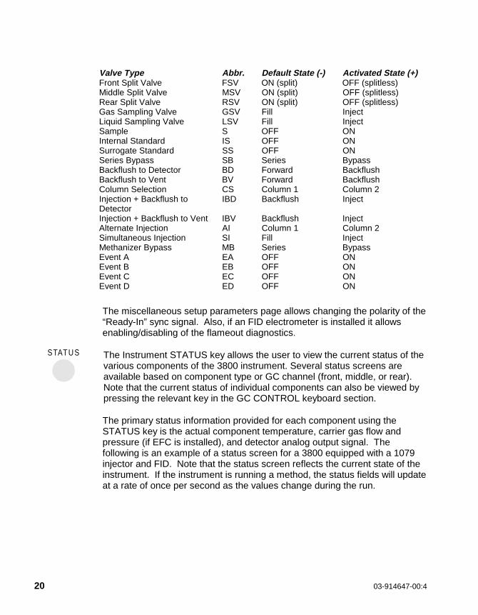
Valves defines the assignment of the seven available external events onthe 3800. These are typically used with either manually controlled 1079split valves (non-EFC) or actuators for sampling or switching valves. Thesetup screen identifies the valve type and default state, i.e., the state it isin when the valve is not energized. The following table summarizes theavailable valve types and their states. Note that the valves are normallyidentified on the 3800 display by their abbreviation, but when the displaycursor is placed on a specific valve its full name is given on the promptline of the display.
20 03-914647-00:4
Valve Type Abbr. Default State (-) Activated State (+)Front Split Valve FSV ON (split) OFF (splitless)Middle Split Valve MSV ON (split) OFF (splitless)Rear Split Valve RSV ON (split) OFF (splitless)Gas Sampling Valve GSV Fill InjectLiquid Sampling Valve LSV Fill InjectSample S OFF ONInternal Standard IS OFF ONSurrogate Standard SS OFF ONSeries Bypass SB Series BypassBackflush to Detector BD Forward BackflushBackflush to Vent BV Forward BackflushColumn Selection CS Column 1 Column 2Injection + Backflush toDetector
IBD Backflush Inject
Injection + Backflush to Vent IBV Backflush InjectAlternate Injection AI Column 1 Column 2Simultaneous Injection SI Fill InjectMethanizer Bypass MB Series BypassEvent A EA OFF ONEvent B EB OFF ONEvent C EC OFF ONEvent D ED OFF ON
The miscellaneous setup parameters page allows changing the polarity of the“Ready-In” sync signal. Also, if an FID electrometer is installed it allowsenabling/disabling of the flameout diagnostics.
STATUS The Instrument STATUS key allows the user to view the current status of thevarious components of the 3800 instrument. Several status screens areavailable based on component type or GC channel (front, middle, or rear).Note that the current status of individual components can also be viewed bypressing the relevant key in the GC CONTROL keyboard section.
The primary status information provided for each component using theSTATUS key is the actual component temperature, carrier gas flow andpressure (if EFC is installed), and detector analog output signal. Thefollowing is an example of a status screen for a 3800 equipped with a 1079injector and FID. Note that the status screen reflects the current state of theinstrument. If the instrument is running a method, the status fields will updateat a rate of once per second as the values change during the run.

INSTALLATIONQuick Guide to the 3800 Keyboard and Display
CP-3800 GC Getting Started Manual 21
ACTIVEMETHOD
EDITMETHOD
CTRL RUNTIME
ENDTIME
������ ������� � ������ ������� � ��
���������� ��,��� 0��-��2 ��5� � �6 ����������� ��,��� 0��-��2 ��5� � �6 �
��*����� ��*����� ����#�����#�
�34 -'�� 01 2�34 -'�� 01 2 �%�%
�"#�� �"�7 0�"8���2 �"#�� �"�7 0�"8���2 ��
�"#�� �$���#$� 0*��2 �"#�� �$���#$� 0*��2 �%�%
�"#�� -'�� ���* 01 2 �"#�� -'�� ���* 01 2 %%
�� -'�� 0�� -'�� 0° 2 2 ��
�� -#�*#� 0�&2�� -#�*#� 0�&2 9�%9�%
� � �
Note that status information may extend beyond one screen depending onthe number of installed options on the GC. If this is the case, the PAGE UP/DOWN keys can be used to move between pages. Status information ispresented in the order: front channel, middle channel, and rear channel.
In addition to the above status information, specific status information onindividual components can be accessed by pressing the relevant key on the3800 keyboard. For example to view the current status of the column oven,the COLUMN OVEN key is pressed. The status information is shown at thetop of the display above the heavy line separating the status information fromthe edit method information.
The following is an example of the screen shown when the COLUMN OVENkey is depressed. The column oven status field is shown at the top of thescreen. Note that the stabilization time is also shown. This represents theperiod of time for which the instrument will stabilize after reaching its settemperatures and before going to the ready state.

22 03-914647-00:4
ACTIVEMETHOD
EDITMETHOD
CTRL RUNTIME
ENDTIME
������ ������� � ������ ������� � ��
��� 01 2: %��� 01 2: % ,)�#�" 01 2: %,)�#�" 01 2: %
���;�"�<����� ���� 0���2: ����;�"�<����� ���� 0���2: � �"#�� -'��: -� �"#�� -'��: -�
-/��� -&��= ��5� � �6 � -/��� -&��= ��5� � �6 �
���*���* ���* 01 2���* 01 2 ���� 01 8���2���� 01 8���2 ��"� 0���2��"� 0���2 ����" 0���2����" 0���2
������"������" %% >> �� ��
�� �%�% �� �� ����
�� �%�% �� %% ����
�#$� -'�� -��#$� -'�� -� �#$� -'�� -66�#$� -'�� -66
� � �
SAM P LEDE LIVERY INJECTO R
GC C ONTROLFLO W /
PRE SSURE
C O LUM NO VEN DETE CTO R O UTPUT
The 3800 contains eight separately programmedanalytical methods. On power up the system defaults tomethod 1. To activate another method the user canpress the ACTIVATE key in the METHOD section andselect from Methods 1 - 8. To edit a method the user canpress the EDIT key in the METHOD section and selectthe method they wish to edit. The currently active methodis by default the method that will be edited unless the userchooses a different method to edit. Both the currentlyactive method and the method being edited are identifiedon the top line of the 3800 display.
A method is edited by entering method parameters into the variouscomponents of the GC CONTROL keyboard section. Components arepresented in the order that the sample goes through the GC system i.e.Sample Delivery� Injector� Flow / Pressure� Column Oven� Detector�Output. The method can be edited by selecting any particular componentand pressing that GC Control key or by stepping through the entire analyticalmethod in the order shown above, i.e., if you enter values for the injectorcomponent, you are automatically taken to the Flow / Pressure component.
The following is an example of a simple analytical method consisting of a1079 isothermal splitless injection using EFC pneumatics, basic columntemperature ramp and FID detection. Only four method components arebuilt: the injector, flow/pressure, column oven and detector.

INSTALLATIONQuick Guide to the 3800 Keyboard and Display
CP-3800 GC Getting Started Manual 23
Note that all heated zones, with the exception of the column oven, areOFF when the 3800 is first powered up.
IN JE C TO R The 1079 method uses three pages of screen displays, a page for setting theinjector temperature (isothermal or temperature programmed), a page forfixed parameters such as coolant ON / OFF, and a page for programming thesplit state of the injector. Note that the injector is identified by its modelnumber and location.
ACTIVEMETHOD
EDITMETHOD
CTRL RUNTIME
ENDTIME
������ ������� � ������ ������� � ��
��� 01 2: % ,)�#�" 01 2: % �*"�� �����: -����� 01 2: % ,)�#�" 01 2: % �*"�� �����: -��
��-�� �34 ��5� � �6 ���-�� �34 ��5� � �6 �
���*���* ���*���* �������� ��"���"� ����"����"
������"������" �%�% >> �� ��
� � �
The above screen represents the temperature settings for the 1079 injector,operated in typical isothermal mode. If the injector were temperatureprogrammed, a new line would be added to add a ramp rate and additionalhold time.
The other important 1079 parameter to program is the split state, which isprogrammed differently depending on whether the 1079 is equipped withmanual pneumatics or EFC. The split state controls the flow of carrier gasthrough the injector during the analytical run. When the split state is OFF,most of the sample injected is directed onto the column. When the split stateis ON, the sample is split in the injector with typically the smaller fractionentering the column and the larger fraction being vented.

24 03-914647-00:4
The example shown below is a splitless injection with EFC pneumatics. Inthis case the injector is held in the split OFF state for a period of time at thebeginning of the run (the sampling time). The injector is then switched to thesplit ON state, typically after 0.5 - 1.5 minutes, to vent the injector of anyresidual solvent. After the injector has been vented, the split ratio can bereduced to conserve carrier gas. In this example the split ratio is reduced to5:1 after 1.5 minutes. The 1079 SPLIT STATE screen is accessed bypressing the PAGE DOWN key on the 3800 keyboard until page 3 of 3 ispresented.
ACTIVEMETHOD
EDITMETHOD
CTRL RUNTIME
ENDTIME
������ ������� � ������ ������� � ��
��� 01 2: �% ,)�#�" 01 2: �% �*"�� �����: -����� 01 2: �% ,)�#�" 01 2: �% �*"�� �����: -��
��-�� �34 ��5� � �6 ���-�� �34 ��5� � �6 �
�������� �*"�� ������*"�� ����� �*"�� ������*"�� �����
������"������" -��-�� -��-��
3%3% -�-� ��
�%�% -�-� %%
� � �
If the 1079 is equipped with manual pneumatics, the split state isprogrammed in the VALVE TABLE section of SAMPLE DELIVERY. Forfurther information on this topic refer to the Sample Introduction section of the3800 Operator’s Manual.
Page two of the 1079 method contains fixed parameters which are rarelychanged. These include turning on and off power to the injector heater andthe coolant supply to the injector.

INSTALLATIONQuick Guide to the 3800 Keyboard and Display
CP-3800 GC Getting Started Manual 25
ACTIVEMETHOD
EDITMETHOD
CTRL RUNTIME
ENDTIME
������ ������� � ������ ������� � ��
��� 01 2: % ,)�#�" 01 2: % �*"�� �����: -����� 01 2: % ,)�#�" 01 2: % �*"�� �����: -��
��-�� �34 ��5� � �6 ���-�� �34 ��5� � �6 �
�34 -'�� ��7�$�34 -'�� ��7�$ -�-�
��"��� -�8-�� ��"��� -�8-�� -�-�
���;"� ��"��� �� 01 2���;"� ��"��� �� 01 2 �%�%
��"��� �����#� 0���2 ��"��� �����#� 0���2 %%
� � �
The 1079 oven must be turned off if the injector is being disassembled formaintenance. Coolant ON / OFF turns on or off the cryogenic supply to theinjector, if installed. Enable coolant refers to the temperature at which thecoolant is turned on when the injector is set to a specific temperature. Forexample if the injector is cooling from 300°C to 50°C, and the coolant enableis set to 250°C, the coolant will be turned on when the injector reaches250°C. Coolant time-out refers to the period of time for which the coolant willremain on after it is turned on. For example, if the set temperature has notbeen reached or the run has not started within the specified time, the coolantsupply will be turned off.

26 03-914647-00:4
FLO W /PRESS URE
If the 3800 is equipped with Electronic Flow Control, then pressing theFLOW/PRESSURE key will bring up the screens associated withprogramming EFC. EFC modules are identified by type and location tocoincide with the sample delivery or injection device with which they areassociated. Type 1 EFC is used with the 1079 Universal Capillary Injector.The following screen is a typical EFC program for type 1 EFC. In this case, apressure program is applied to keep the column flow rate constant while thecolumn temperature is ramped. For further information, refer to the SampleIntroduction section of the 3800 Operator’s Manual.
ACTIVEMETHOD
EDITMETHOD
CTRL RUNTIME
ENDTIME
������ ������� � ������ ������� � ��
�"#�� �$���#$� 0*��2: � �"#�� �"�7 0�"8���2: � �"#�� �$���#$� 0*��2: � �"#�� �"�7 0�"8���2: �
/����$ &�"�)��. 0)�8��)2: �% ����" �"�7 0�"8���2: �/����$ &�"�)��. 0)�8��)2: �% ����" �"�7 0�"8���2: �
�*"�� �����: -66�*"�� �����: -66
��-�� �� = �.*� � ��5� � �6 ���-�� �� = �.*� � ��5� � �6 �
���*���* �$���#$��$���#$�0*��20*��2
���� 0*��8���2���� 0*��8���2 ��"� 0���2��"� 0���2 ����" 0���2����" 0���2
������"������" �� >> �� ��
�� �%�% %% %% �3�3
� � �
CO LU M NO V EN
The column oven method section has two screens, one with the column oventemperature conditions and the second with fixed parameters. Thetemperature control screen could have one line of initial conditions in thecase of isothermal operation, or a table in the case of temperatureprogrammed operation.
The total time represents the cumulative time up to that point in the run. TheTurn Oven Off softkey turns off the column oven heater and fan to allowaccess to the oven. Similarly, the Turn Oven On softkey is used to turn thecolumn oven heater and fan back on.

INSTALLATIONQuick Guide to the 3800 Keyboard and Display
CP-3800 GC Getting Started Manual 27
ACTIVEMETHOD
EDITMETHOD
CTRL RUNTIME
ENDTIME
������ ������� � ������ ������� � ��
��� 01 2: %��� 01 2: % ,)�#�" 01 2: %,)�#�" 01 2: %
���;�"�<����� ���� 0���2: ����;�"�<����� ���� 0���2: � �"#�� -'��: -� �"#�� -'��: -�
-/��� -&�� ��5� � �6 � -/��� -&�� ��5� � �6 �
���*���* ���* 01 2���* 01 2 ���� 01 8���2���� 01 8���2 ��"� 0���2��"� 0���2 ����" 0���2����" 0���2
������"������" %% >> �� ��
�� �%�% �� %% �3�3
�#$� -'�� -��#$� -'�� -� �#$� -'�� -66�#$� -'�� -66
� � �
Page 2 of the Column Oven parameters consists of fixed parameters whichare rarely changed. These consist of coolant on/off, coolant activationtemperature, coolant time-out and stabilization. The first three operate thesame as described above for the 1079. Stabilization time is the time takenfor the column oven to stabilize at its set temperature before allowing the GCto go to the ready state.

28 03-914647-00:4
DETEC TO R The 3800 detector methods generally have two method parameter pages andan additional adjustments page. The adjustments page is generally used foradvanced features of the specific detectors and also for setting detector gasflows, if EFC is installed. The following is an example of an FID method. Forthe FID the only adjustments item is the detector time constant (Fast orSlow).
ACTIVEMETHOD
EDITMETHOD
CTRL RUNTIME
ENDTIME
������ ������� � ������ ������� � ��
��� 01 2: � ,)�#�" 01 2: � ��5��" 0�&2: %�%��� 01 2: � ,)�#�" 01 2: � ��5��" 0�&2: %�%
��-�� �� ��5� � �6 ���-�� �� ��5� � �6 �
-'�� ��7�$:-'�� ��7�$: -�-�
���*�$��#$� 01 2:���*�$��#$� 01 2: ��
�"�)�$���)�:�"�)�$���)�: -�-�
���5�:���5�: ����
�?�����?���� ,��-���-,��-���- , @��������, @��������
� � �
The second page of method parameters for the FID allows the user to timeprogram certain events such as range and autozero during the analytical run.
ACTIVEMETHOD
EDITMETHOD
CTRL RUNTIME
ENDTIME
������ ������� � ������ ������� � ��
��� 01 2: � ,)�#�" 01 2: � ��5��" 0�&2: %�%��� 01 2: � ,)�#�" 01 2: � ��5��" 0�&2: %�%
��-�� �� ��5� � �6 ���-�� �� ��5� � �6 �
�������� ���5����5� ,#��<�$�,#��<�$�
������"������" ���� �-�-
%% ���� A��A��
(%(% ���� �-�-
�?�����?���� ,��-���-,��-���- , @��������, @��������
� � �

INSTALLATIONColumn Installation and Conditioning
CP-3800 GC Getting Started Manual 29
Column Installation and Conditioning
ConnectColumn toInjector
Your GC arrives ready for installation of an analytical column. On firstinstallation, a new column needs to be conditioned. Conditioning isperformed with the detector end of the column unattached.
Hot surfaces are exposed.
You may need to install and condition a new column after your GC has beenin use for some time. Reset all injector, detector and column ovens to≤ 50°C to avoid burn hazards when connecting column to injector anddetector parts inside the oven.
Prior to installing your column, check that the factory-installed injector isequipped with the proper insert for your application. Factory-installedinjectors, other than the 1041, have a glass insert suitable for a variety ofapplications. If your application calls for a different insert, replace thefactory-installed insert prior to installing your column. Refer to the Injectorsection of the Operator’s Manual for instructions to replace the insert. Thefactory-installed inserts for the injectors are shown below.
Injector Insert Information Part Number1061 4 mm ID Flash (530µ) 03-918339-001079 Open 2 mm ID Splitless 03-918466-00
Nuts andFerrules forCapillaryColumns
Capillary columns are generally installed with acapillary column nut (P/N 03-949551-00) and asingle reversed ferrule, as shown in thediagram. For connection to the TCD, a specialcapillary adapter (P/N 03-925605-01) is used.
• A Quick Connect Kit (P/N 03-925355-90)facilitates easy connection of capillarycolumn to injector and detector. The kitcomes with instructions and contains:column depth scale, knurled split nuts (2),and graphite jacketed ferrules (2 each of 0.4,0.5 and 0.8 mm ID, for 250 µm, 320 µm, and530 µm columns respectively).
ReversedFerrule
CapillaryColumnNut
Fused SilicaColumn

30 03-914647-00:4
Three types of ferrules are common: graphite, Vespel® or polyimide, andgraphite/Vespel.
• Do not use graphite with ECD or GC/MS systems.
• Ferrule ID is based on the diameter of the capillary column. See thefollowing table.
Part Number
Ferrule ID(mm)
Fitting Size(inches)
Column ID(microns)
Polyimide(10/pk)
Graphite(10/pk)
Polyimide/Graphite (10/pk)
No hole 1/16″ fitting — 28-694503-01 — 28-694590-01
0.4 mm 1/16″ fitting 50 - 250 28-694586-01 28-694583-01 28-694580-01
0.5 mm 1/16″ fitting 320 03-908361-01 28-694561-01 28-694581-01
0.8 mm 1/16″ fitting 530 28-694552-01 28-694042-01 28-694582-01
Capillary column connection to the Micro-TCD requires a special series ofgraphite/Vespel ferrules (see table below).
Column ID Ferrule IDFerrule
Part Number0.1 mm 0.4 mm CP858890.25 mm 0.4 mm CP858890.32 mm 0.5 mm CP4701000.53 mm 0.8 mm CP470101
INSTALLATIONColumn Installation and Conditioning
CP-3800 GC Getting Started Manual 31
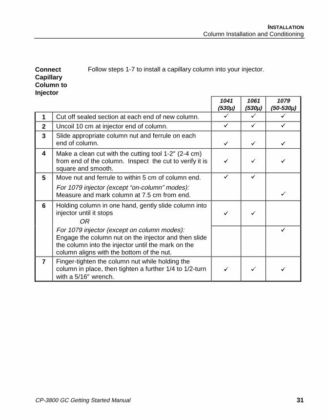
ConnectCapillaryColumn toInjector
Follow steps 1-7 to install a capillary column into your injector.
1041(530µ)
1061(530µ)
1079(50-530µ)
1 Cut off sealed section at each end of new column. � � �
2 Uncoil 10 cm at injector end of column. � � �
3 Slide appropriate column nut and ferrule on eachend of column. � � �
4 Make a clean cut with the cutting tool 1-2″ (2-4 cm)from end of the column. Inspect the cut to verify it issquare and smooth.
� � �
5 Move nut and ferrule to within 5 cm of column end.
For 1079 injector (except “on-column” modes):Measure and mark column at 7.5 cm from end.
� �
�
6 Holding column in one hand, gently slide column intoinjector until it stops
OR� �
For 1079 injector (except on column modes):Engage the column nut on the injector and then slidethe column into the injector until the mark on thecolumn aligns with the bottom of the nut.
�
7 Finger-tighten the column nut while holding thecolumn in place, then tighten a further 1/4 to 1/2-turnwith a 5/16″ wrench.
� � �

32 03-914647-00:4
Nuts andFerrules forPackedColumns
• Metal packed columns are usually installed with a metal 2-piece ferrule.(A commonly used metal packed column is 1/8″ OD stainless steel. Ituses a 1/8″ ID stainless steel ferrule.)
• Glass packed columns are 1/4″ OD and are installed with a graphitefront ferrule and a metal back ferrule installed backwards. See diagrambelow.
Connect aPackedColumn tothe Injector
Follow the steps below to install a new packed column into your 1041 or1061 injector. Note that the injector must first be converted for packedcolumn use by installing the appropriate adapters.
1 Place nuts and ferrules on both ends of column as shown in theprevious diagram.
2 If your column is metal, insert it into the injector fitting and gentlypush until it stops. Manipulate the column so the detector endpoints into the oven
ORIf your column is glass, insert it into the injector, rotate it slightly sothe detector end is out of alignment with the detector and pushgently until the end is near but not touching the oven ceiling.
3 Hold the column in place and thread the nuts by hand.
4 Tighten the nut finger-tight, then give it a further 3/4-turn with asmall wrench.
A Two Piece FerruleB Column NutC Back FerruleD Front FerruleE Column NutF Metal Back Ferrule
Installed BackwardsG Graphite Ferrule

INSTALLATIONColumn Installation and Conditioning
CP-3800 GC Getting Started Manual 33
Varian TestColumn
At points throughout this manual, specific values and conditions are givenfor the analysis of Varian Test Samples on Varian Test Columns. Thefollowing table provides information on Varian Test Columns.
Varian Test Columns
Column DescriptionFor use with
Injector ModelsPart
Number
Packed 50 cm x 1/8″ OD stainless steelOV-101.
1041/1061Packed Adapters
03-912300-30
Capillary 4m x 320µ ID DB-1 fused silica. 1079 03-912805-99
Capillary 4m x 320µ ID DB-1 fused silica (a)connected to a short pre-column of 0.53 mmfused silica (b) using a Press-Fit connector(c). The above parts are also available as akit (d).
1041/1061 03-912805-99 (a)00-997564-03 (b)00-997668-03 (c)03-912809-90 (d)
IdentifyCarrier GasControls andTurn on Flow
Gases are plumbed at the factory through the rear bulkhead fittings into theinlet manifold, then to the pneumatic controls in the pneumaticscompartment. The pneumatic controls can be either electronically controlled(EFC) or manually controlled and are different for each injector system.
If your injectormodel is a ... Carrier gas flow is regulated by a ...1041/1061 Type 3 EFC or upgrade to type 4 with valving.
1079 Type 1 EFC or Flow controller (controls flow intoinjector) and a Back pressure regulator (controls flowthrough column)
• Carrier gas flow is adjusted at the user interface for EFC or at thepneumatics panel for manual pneumatics. For manual pneumaticscarrier gas systems, identify the controls for carrier gas flow at thepneumatics panel for your injector system. These pneumatic controlsare identified by their location, i.e., front, middle, rear.
• Turn on carrier gas flow by adjusting the manual flow controller orsetting a positive pressure or flow on the EFC system.
• Verify that there is a positive pressure on the pneumatics panel pressuregauge or EFC status screen.

34 03-914647-00:4
1079 Split VentFlow andSeptum PurgeFlow
Whether you are making an injection in the split or splitless mode, a splitvent flow rate needs to be set. In this example, the split vent flow is set to100 mL/min. The split state is set in the Injector section of the 3800method if EFC is installed and in the VALVE TABLE section of SAMPLEDELIVERY if manual pneumatics are installed. In addition to a split state aseptum purge flow rate should also be set. The following information is forsetting a split vent flow rate with EFC installed. For a 1079 with manualpneumatics see the Injector section of the Operator’s Manual for furtherinformation.
1. Press the FLOW PRESSURE key and set the appropriate headpressure for your analytical column.
2. Press the INJECTOR key in the GC CONTROL section of the 3800keyboard and select the 1079 injector by location.
3. Press the PAGE down key to access the SPLIT STATE screen (page 3of 3). When Electronic Flow Control is installed, in addition toprogramming the split state, the split ratio can also be programmed.
4. Set the initial split state to ON and set the split ratio to 100.
5. Open the column oven door and adjust the septum purge needle valvelocated above the column oven until the flow rate is in the range 3 - 5mL/min. For EFC equipped systems this value has to be entered in theseptum purge calibration routine. Use the following procedure to carryout septum purge calibration:
• Press the STATUS key and note the current column pressure forthe channel you are using (front, middle, or rear).
• Select the edit SETUP option and select EFC. Select the injectoryou are setting up by specifying the location (front, middle or rear).
• Press the SEPTUM PURGE CALIBRATION softkey. You will beprompted to enter the injector pressure and septum purge flowrate. Enter the pressure value noted above and the septum purgeflow rate measured earlier. The septum purge calibration iscompleted automatically when you press the “Save and Exit”softkey.

INSTALLATIONColumn Installation and Conditioning
CP-3800 GC Getting Started Manual 35
Set CarrierGas FlowRate toConditionColumn
To condition the column, flow rates need only be approximate. For packedcolumns and large bore (0.53 mm ID) capillary columns set the flow rate to15 - 30 mL/min. Press the FLOW / PRESSURE key, select the appropriateinjector by location, and set the initial flow to 15 - 30 mL/min(15 mL/min for a large bore column and 30 mL/min for a packed column).
Use the following guide to set an appropriate column flow for the 1079injector with narrow bore capillary columns. With manual pneumatics thepressure is set using the 1079 back pressure regulator on the pneumaticspanel. If the 1079 has EFC press the FLOW / PRESSURE key, select theappropriate injector by location and set the pressure as follows:
Column ID Head Pressure250 µm 25 psi320 µm 15 psi530 µm 5 psi
Note forCapillaryColumnUsers
Verify gas is flowing through the column by dipping the detector end ofcolumn into a beaker containing a solvent, such as isopropanol. Positivecarrier gas flow should be indicated by a stream of bubbles.
Conditioningthe Injectorand Column
It is important to establish the maximum recommended conditioningtemperature for the installed column. This information is provided with thecolumn or can be obtained from the column manufacturer. The maximumallowable temperature for the column does not have to be used forconditioning purposes. In general the column should be conditioned at 20°Cabove the maximum temperature used in the analytical method, or 20°Cbelow the maximum operating temperature of the column, whichever islower.
CAUTIO NA GC column may be irreversibly damaged if it is heated with air ormoisture present in the pneumatic system. It is important to purge thecolumn with inert carrier gas before heating the column. After thecolumn flow is established, allow the carrier gas to purge through thecolumn for 15 - 20 minutes before heating it.

36 03-914647-00:4
In this example the injector and column are conditioned at 250°C for twohours. The column is programmed to 250°C at 5°C/min as a gentletemperature program is generally recommended for column conditioning.After this conditioning is complete, allow the column oven to cool and re-tighten the column nut attaching the column to the injector. This is especiallyimportant when graphite ferrules are used.
To condition the injector press the INJECTOR key in the GC CONTROLsection of the 3800 keyboard. Set the injector temperature to 250 (initialtemperature for a 1079). If a 1079 injector is being used, ensure that theinitial split state is ON and that no program is present to time program thesplit state (the split state table should only consist of the initial line). Verifythat the split ratio is set to 100.
To condition the column press the COLUMN key in the GC CONTROLsection of the 3800 keyboard and build the following column oven method.
Initial Column Temperature: 50°C
Hold Time: 5 min
Step 1 temperature: 250°C
Step 1 ramp rate: 5°C/min
Step 1 Hold Time: 120 min
When the 3800 reaches the READY state indicated by the READY LED beinglit, press the START key to begin the conditioning process.
ConnectCapillaryColumn toDetector
After the column has been conditioned, follow the steps below to connect thecapillary column to the detector.
Hot surfaces are exposed.
1 Check that the capillary column nut and ferrule are installed on thecolumn. Note that if the TCD is used with capillary columns, aspecial capillary adapter (PN 03-925605-01) is used on the TCDinlet.DO NOT use graphite ferrules with the ECD.
2 Uncoil about 20 cm from end of column.

INSTALLATIONColumn Installation and Conditioning
CP-3800 GC Getting Started Manual 37
3 Move the column nut and ferrule to within 5 cm of the column end.Find the column insertion depth for your detector in the diagrambelow. Measure the correct distance from the end of the columnand mark this distance. Refer to diagram below for correctdistances. DO NOT let the column nut and ferrule fall past thismark. The marking medium can contaminate the ferrule.
ColumnInsertionDepths forVarianDetectors
N O T TO S C A LE
FID/TSD
9.5 cm
E CD
10.5 cm
TCD
3.9 cm
Cap illary C o lum n N utP /N 03-949551-00
Ferru leFused S ilica C olum n
PFPD
9.7 cmC
olum
nIn
sert
ion
Dep
th
For the Micro-TCD, the end of the column should be flush with the end of theferrule when installed on the detector fitting.

38 03-914647-00:4
4 Place the column into the base of the detector.
5 Thread the capillary column nut and ferrule finger-tight.
6 Gently slide the column into the detector until the mark on thecolumn aligns with the bottom edge of the column nut.
7 Continue to hold the column as you tighten the nut just enough tohold the column firmly in place and to create a good seal.
Connect MetalPackedColumn toDetector
After conditioning your column and cooling the GC, follow the steps belowto connect your metal packed column to the detector. Note that theappropriate packed column adapter must be installed.
Hot Surfaces are Exposed.
1 If using a detector other than TCD, locate the packed columndetector adapter in the Packed Column Kit and install on the inletto the detector. The TCD inlet is designed for packed columninstallation.
2 Insert the open end of the packed column into the detector inlet oradapter, and push until it reaches a stop.
3 Hold the column in place and finger-tighten the column nut. Then,with a 7/16″ wrench, tighten a further 3/4-turn past finger-tight. Onsubsequent installations, tighten the nut 1/4 to 1/2-turn past finger-tight.
Check forLeaks
Inspect your GC system for leaks before heating. An electronic leakdetector is the most reliable method to check the injector and detectorfittings for carrier gas leaks.
CAUTIO NNever use soaps, such as Snoop®. These may contaminate thesystem and cause permanent damage to capillary columns. If a liquidleak detector is desired, try a 50/50 mixture of isopropanol/water.

CP-3800 GC Getting Started Manual 39
Basic Operation
IMPORTANT Note: At points throughout this section, specific values and conditions aregiven for analysis of the Varian test samples on Varian test columns.Your analytical column and application may require different valuesand conditions. Please ascertain the range of operatingtemperatures for your analytical column and make sure your settingsare within this range.
Setting Carrier and Detector Gas Flow Rates
The following table indicates the typical values for carrier and detector gasflow rates. For practical purposes a generalized carrier gas flow rate of 2mL/min is used for capillary columns. Note that the carrier gas and make-upcombined flow is typically 30 mL/min.
Table 2 Flow Rates for Carrier and Detector Gases for the 3800 Gas Chromatograph
DetectorCarrier
Gas
Carrier Gas Flow Rate(mL/min)
Packed CapillaryMake-Up
Gas
Make-Up +Carrier
Gas FlowRate
(mL/min)
DetectorGasAir 1
(mL/min)
DetectorGasAir 2
(mL/min)
DetectorGasH2
(mL/min)
ECD N2 orAr/CH4
30 ±1 1 - 15 N2 orAr/CH4
30 ±1 — — —
FID N2, H2 orHe
30 ±1 1 - 15 N2 or He 30 ±1 300 ±10 — 30 ±1
TCD* N2, He orH2
30 ±1 1 - 15 Same asCarrierGas
30 ±1 — — —
PFPD N2, He orH2
30 ±1** 1 - 10 None __ 17 ±1 10 ± 1 13 ±1
TSD N2 or He 30 ± 1 1 - 15 Same asCarrierGas
30 ±1 175 ±10 — 4 ±0.2
Micro-TCD***
H2, or He — 1 – 5 None —
*TCD Reference Flow – Rate for carrier gas flow through the reference cell is 30 ±1 mL/min.
** PFPD with packed columns – an effluent splitter is used to reduce the carrier flow to the detectorto < 5 mL/min.
***Micro-TCD reference flow is provided by a reference column of the same length and ID as theanalytical column.

40 03-914647-00:4
The following instructions are for instruments configured with manualpneumatics. Gas flows for detectors with EFC are set in the AdjustmentsSection of the detector method.
Follow the steps below to set all gas flow rates on the 3800 GasChromatograph. Flows are typically set with carrier gas first followed bymake-up and detector fuel gases. The most convenient way to measure orverify gas flows is at the detector exit. Adapters are provided in the individualdetector accessory kits for this purpose.
1 Attach a bubble or digital flowmeter to the detector outlet using theappropriate adapter.
2 Turn off make-up and detector gases at the pneumatics panel. Fora needle valve this is accomplished by turning the needle valvecartridge knob fully clockwise. For a flow controller this isaccomplished by turning the flow controller knob fully counter-clockwise or until the turns counting dial reads zero.
3 Observe reading on flowmeter. Ensure it is within the rangedescribed in the table for carrier gas flow rates.
4 Adjust the carrier gas flow using the manual pneumatics controls onthe pneumatics panel or by adjusting the Electronic Flow Control toachieve the desired flow rate.
5 For a capillary system, turn on the make-up needle valve and adjustto achieve the desired flow rate. The combined carrier and make-upflow should be 30 mL/min. Adjustment is done with a small flatscrewdriver inside the needle valve cartridge knob.
6 Turn on the relevant detector fuel gases in the sequence hydrogenfollowed by air. Use the table below to calculate the combined flowsfor the specific detector. For the TSD adjust the hydrogen flowcontroller until the turns dial reads 400.
DetectorCarrier +make-up
Carrier + make-up + hydrogen
Carrier + make-up +hydrogen + air1
Carrier + make-up +hydrogen +air1 +air2
FID 30 60 360
TSD 30 34 209
PFPD 2 15 32 42

BASIC OPERATIONCondition the GC System
CP-3800 GC Getting Started Manual 41
Condition the GC System
As the injector and column were conditioned earlier, this procedurerepresents a quick conditioning of the entire GC system including thedetector. Follow the steps below to build an analytical method to conditionthe GC system.
1 Press the INJECTOR key in the GC CONTROL section of the3800 keyboard and verify that the injector temperature is 250°C. Ifthe injector is a 1079 verify that the initial split state is ON and thatthere is no split time program. Set the split ratio to 100.
2 Press the COLUMN key and set the initial column oventemperature to 250°C.
3 Press the DETECTOR key and set the detector oven temperatureto 300°C. If the detector is an FID, wait for the detector zone toget above 100°C and then press the ignite softkey to ignite theflame.
4 Allow the system to condition for one hour.
Build a Method to Analyze a Test Sample
The conditions for running a test sample depend on the sample chosen. Thetest sample is typically one of the following:
• the column test mixture supplied by the column manufacturer,
• a Varian Test Sample, or
• a test mixture you select as an indicator of system performance for aparticular analysis.

42 03-914647-00:4
Method to Analyze a Varian Test Sample on a Varian Test Column
Varian Test SamplesFor use with … Sample Composition Part NumberECD 33 ppb Lindane and Aldrin in iso-octane 82-005048-02FID (Packed Column) 0.03% C14, C15, C16 in iso-octane 82-005048-00FID (Capillary Column) 0.003% C14, C15, C16 in iso-octane 82-005048-07TCD 0.3% C14, C15, C16 in iso-octane 82-005048-01PFPD 0.002% n-dodecanethiool, tributyl phosphate and
methyl parathion, and 0.4% n-pentadecane in iso-octane
82-005048-03
TSD 2 ppm azobenzene and methyl parathion, 4 ppmmalathion, and 4000 ppm heptadecane in iso-octane
82-005048-04
Micro-TCD 68 mg/mL n-hexane in iso-octane CP84886
Note: These conditions may not conform to the requirements of your analytical column. Do notexceed your column’s Tmax. See Column Manufacturer’s specifications for your column.
For Systems with 1041/1061 Injectors : Method Settings to Analyze Varian Test Samples onVarian GCs Installed with Varian Test Columns
Note: Capillary columns use a temperature program while packed columns use isothermal conditions.ECD FID TCD1 TSD PFPD Micro-TCD 2
Initial column temp (°C) 80 80 80 80 80 40Initial column hold time (min) 1 1 1 1 1 1
Final column temp (°C) 200 200 200 200 200 200
Final colum hold time (min) 5 5 5 5 5 5Initial column temp (°C) (Isothermaloperation)
190 140 140 175 175 —
Initial column hold time (min)(Isothermal operation)
15 15 15 15 15 —
Injector temp (°C) 220 220 220 220 220 150
Detector temp (°C) 300 300 220 300 300 110
Range 10 10 0.05 12 10 0.5Initial Autozero On On On On On OnTSD bead current (amps) 3.0 ±0.31 TCD Filament temp: 270 ±20°C; filament current: 200 ±10 mA, polarity: positive2 Micro-TCD Test sample must be diluted 1:20 before injection on a 1041/1061 injector.

BASIC OPERATIONPrepare the Test Sample
CP-3800 GC Getting Started Manual 43
For Systems with 1079 InjectorsMethod Settings to Analyze the Varian Test Sample on Varian GCs
Installed with the Varian Test Column
ECD FID TCD1 TSD PFPD Micro-TCD
Initial column temp (°C) 80 80 80 80 80 40
Initial column hold time (min) 1 1 1 1 1 1
Program 1 final temp (°C) 200 200 200 200 200 200
Program 1 ramp rate (°C/min) 20 20 20 20 20 20Program 1 hold time (min) 5 5 5 5 5 1
Injector temp (°C) 220 220 220 220 220 150
Detector temp (°C) 300 300 220 300 300 110
Range 10 11 0.05 12 10 0.5Initial Autozero On On On On On OnTSD bead current (amps) - - - 3.0 ±0.3 - -
Injection mode Splitless SplitInitial split state OFF OnStep 1 time (min) 0.75 -Step 1 split state ON -Step 1 split ratio 100 25
1 TCD Filament temp: 270 ±20°C; filament current: 200 ±10 mA, polarity: positive
Prepare the Test Sample
You are now ready to prepare your sample. For preparation of samples forautomated injection, please refer to the 8200/SPME AutoSampler Operator’sManual, P/N 03-914692-00.
You may inject your sample neat or diluted in a solvent. The Varian PFPDtest sample should be diluted 1:20 in iso-octane if you intend to use it for asplitless injection. The choice of solvents depends on a number of factors,including component solubility, type of detector, and polarity of the analyticalcolumn. Select solvents to match the polarity of your column.
Solvents for GC
Following are some recommended solvents for non-polar, intermediate, andpolar phase columns.

44 03-914647-00:4
Recommended Solvents for Gas Chromatography
Column Phase Recommended Solvent Boiling Point(° C)
Non-Polar • Pentane 36.1• 100% Methyl • n-Hexane 69.0• 5% Phenyl, 95% Methyl • Cyclohexane 80.7
• Iso-octane 99.3• Benzene 80.1• Toluene 110.6• Ethyl Ether 34.6• Methyl tert-butyl ether 55.2• Methylene Chloride 39.8• Chloroform 61.2• Carbon Disulfide 46.5
Intermediate • Ethyl Acetate 77.0• 50% Phenyl, 50% Methyl • Acetone 56.5
• Methyl iso-butyl ketone 127.0• Acetonitrile 81.6
Polar • Methanol 64.7• Polyethyene Glycol • Ethanol 78.5
• 2-Propanol 82.5• n-Butanol 117.7
Sample Volume and Injection Rate
The quality of your chromatogram can be greatly affected by the samplevolume and injection rate. These vary according to the type of injector andcolumn you are using. Shown below are some recommended samplevolumes and injection rates. Draw the appropriate volume of sample intoyour syringe and inject at specified rate.
Injector On-Column, Flash Vaporizing(1041/1061)
Split(1079)
Splitless(1079)
Column For• Large-bore Capillary Columns
(0.53 mm ID)• Packed Columns
ForAllCapillaryColumns
ForAllCapillaryColumns
SampleVolume in µL
• 0.1-1• 1 - 5
0.2-1 1-5
Injection Rate,in µL/sec
• 0.5-5• 1 - 10
5 1
Inject the Test Sample
CP-3800 GC Getting Started Manual 45
Inject the Test Sample
Use 1µL of the Varian test sample for all detectors. In addition, if you areusing a PFPD, make a 1:20 dilution of the test sample in iso-octane. With theREADY light on at the GC and the appropriate volume of test sample in yourinjection syringe, you are ready to make your injection. For automatedinjection of samples, please refer to the 8200/SPME AutoSampler Operator’sManual, P/N 03-914692-00.
• To inject your sample, insert the syringe needle into the injector inlet,press the syringe barrel against the injector switch and depress itcompletely, simultaneously pressing down the syringe plunger. Removethe syringe from the injector immediately.
• The RUN light comes on and stays on until the analysis ends. The runmay be stopped by pressing the STOP key.
• Compare the resulting chromatogram with your known testchromatogram.
• If you are analyzing the Varian Test Sample on a Varian Test Column, youmay compare your resulting chromatogram with the appropriate testchromatogram in the Detector section of the Operator’s Manual. Theretention times will be close to those shown in the manual. The peakheights may be considerably different.
• Failure to duplicate the results you expected may indicate an installation,operation or instrument problem. This problem must be corrected beforeproceeding.

CP-3800 GC Getting Started Manual 47
Maintenance
Overview
It is important for the GC user to learn general maintenance techniques andcarry these procedures out on a regular basis. Some common GCmaintenance procedures are changing septa and injector inserts, checkingfor leaks, conditioning columns and changing filters. In this sectionmaintenance information is presented under four headings: general GCmaintenance, injector maintenance, column maintenance and detectormaintenance.
Note that many maintenance procedures, such as repair or replacement ofelectronic components, should be performed by a qualified Varian servicerepresentative. For maintenance problems where mechanical or electricalassemblies need to be repaired or replaced please call your local Varianservice center.
There are certain maintenance tasks that should be carried out on a routinebasis. These regular procedures are done to ensure that the 3800 GasChromatograph will continue to operate at optimum performance. Thefollowing is a brief summary of some common maintenance tasks and theirtypical frequency:
Maintenance Task FrequencyChange septa Typically 50 - 100 injections
Check column nuts are tight Daily
Condition column Daily or as required
Change injector inserts, if necessary Weekly
Check gas supplies Weekly
Leak check Monthly
Change gas cylinders Quarterly or as required
Condition system Semiannually
Clean detectors When performance deteriorates
Replace gas purifiers Annually or as required
Perform AutoCalibrate (EFC) Semi-annually

48 03-914647-00:4
General GC Maintenance
The common general GC maintenance tasks are checking and changing gassupply cylinders, leak checking, and changing gas purifier filters. Theseshould be performed at the frequency suggested above. The followingprocedures are critical to the successful long term operation of a GasChromatograph. It is very important to leak check the system on a routinebasis and to ensure the quality of gas supplies, particularly the carrier gas.
Check andRenew GasSupplies
The pressure of the various GC gas supplies should be checked on a weeklybasis and the following guidelines used for frequency of renewing supplies:
Carrier gas: The carrier gas supply cylinder should be changed when itspressure drops below 200 psi. This ensures that high purity carrier gas isalways supplied to the instrument. With typical usage on one GasChromatograph an A-size cylinder of carrier gas should last for three to sixmonths. Note that this usage includes also using the carrier gas as the supplyof make-up to the detectors. When a new cylinder is installed the regulatorand tubing should be purged with carrier gas before connecting to the GC.This will avoid introducing a large amount of air into the GC.
Detector fuel gases: The typical detector fuel gases are hydrogen and air.These should be changed when the supply pressure drops below 200 psi.Typically an A size cylinder of hydrogen used on one GC with one FlameIonization Detector lasts about six months. However, due to the high flow rateof air used in a Flame Ionization Detector this supply will need renewing morefrequently. For this reason it is worthwhile to consider a clean supply ofcompressed air for FID equipped instruments.
Leak Check Leak checking is one of the most important maintenance tasks that is carriedout on a Gas Chromatograph. The following information refers to generalleak checking procedures for the 3800 Gas Chromatograph. Specificinformation regarding individual 3800 components will be presented in therelevant part of this maintenance section.
Leaks in the GC system can lead to poor chromatographic performance ordamage components such as the analytical column. The presence of oxygenin the GC carrier gas at elevated temperatures can lead to permanent columnphase degradation. While the use of an oxygen filter on the carrier supply tothe instrument can help, leaks downstream of the filter are generally morelikely to be the problem.

MAINTENANCEGeneral GC Maintenance
CP-3800 GC Getting Started Manual 49
The use of soap-based leak detection fluids is not recommended for a highperformance capillary Gas Chromatograph due to the danger of introducingcontaminants into the system. If leak detection fluids are being used theyshould only be used outside the Gas Chromatograph, i.e., to verify there areno leaks in the plumbing to the Gas Chromatograph. If a leak detection fluidis being used inside the Gas Chromatograph, an alcohol such as isopropanolor a 50:50 mixture of isopropanol and water should be used. Use a dropperor syringe to place a few drops of leak detection fluid on the desired fittingand monitor the area for bubble formation.
The most important step in leak checking is to verify that the GC system canhold pressure. This is done by removing the column from the injector, sealingall exits from the injector and pressurizing the system. Use the followingprocedure to leak check 3800 injectors:
Note: When conducting leak check procedures it is important to completelyseal all carrier gas exits, including septum purge and split vent outlets. Ifmore than one injector is present, then the outlets of all the injectors must besealed. The following procedure refers to one injector but should beduplicated for every injector on the 3800.
1 Set the column oven and the injector zone temperatures to 50°Cand allow them reach this temperature. This allows safe handling ofinjector surfaces.
2 Remove injector septum nut and install a new septum. An olderseptum can often be the source of a substantial leak.
3 Remove the column from the injector. Use the appropriate nut andferrules to seal the base of the injector. For packed columnsystems use a 1/4″ Swagelok blank off plug (P/N 16-000154-00).For capillary systems use a capillary nut (P/N 03-949551-00) with ano hole ferrule (P/N 28-694590-01).
4 If the injector is a 1079, then the septum purge and split ventoutlets must be sealed. The septum purge outlets are located onthe top frame surrounding the column oven, behind the columnoven door. The split vent outlets are located on the left side panelof the 3800. Seal the septum purge by removing the outlet fittingfrom the septum purge valve and replacing it with a blank off plug(P/N 16-000154-00). Seal the split vent outlet by installing aSwagelok union on the outlet tube and sealing it with a blank offplug.

50 03-914647-00:4
5 With all outlet ports plugged, pressurize the system to 20 - 30 psi.This can be accomplished by adjustment of manual pneumaticcontrols or Electronic Flow Control. For information on settingcarrier gas pressure see the Basic Operation section of thismanual.
6 Shut off the carrier supply at the source and monitor the displayedpressure at the GC for 15 minutes. The pressure should not dropmore than 0.5 psi in 15 minutes.
Leak checking ensures that there are no leaks in the GC system up to andincluding the injector assembly. If the indicated pressure on the GC drops bymore than 0.5 psi during the 15 minute test period, this indicates that there isa positive leak in the system. Finding such a leak, particularly if it is a smallleak, can be very difficult. In general the best approach is to systematically gothrough the pneumatic system from the source and tighten each fitting untilthe leak is eliminated. It is important to note that leaks are often found in thecarrier gas supply to the GC.
Locate leaks with an electronic leak detector or leak detection fluid. Anelectronic helium leak detector is available from Varian (P/N 01-900153-01).This device can detect helium concentration in the air as low as 2 ppm and isvery effective at identifying the precise location of a helium leak from a GCsystem.
Gas PurifierReplacement
The most common gas purifiers used in gas chromatography are moisturetraps for removing water vapor, hydrocarbon traps for removing low levels ofhydrocarbon contaminants and oxygen traps for removing low levels ofoxygen. In general the choice of filter depends on the application anddetector used. Carrier gas should contain less than 1 ppm oxygen, moistureand trace hydrocarbon contaminants. A combined moisture / hydrocarbonfilter is recommended for general applications to maintain detectorbackground levels at their lowest possible level. If the detector used is anECD or MS an oxygen filter should be employed as well.
Carrier gas filters are typically located on the rear panel of the 3800. Variansupplies several types of carrier gas purifiers. These include a combinedmoisture / hydrocarbon trap, indicating moisture trap, and indicating or non-indicating oxygen traps. While the choice of purifier depends on the individualconfiguration and performance expectations, the following configuration isrecommended for maximum carrier gas purity and protection.

MAINTENANCEGeneral GC Maintenance
CP-3800 GC Getting Started Manual 51
The carrier gas should first pass through a hydrocarbon trap, then anindicating moisture filter, then a high capacity oxygen trap and finally throughan indicating oxygen trap. As moisture reduces the effectiveness of anoxygen trap, a moisture trap should always be placed in front of an oxygentrap. When the indicating oxygen trap begins to change color, the highcapacity oxygen trap should be changed immediately. The moisture trapshould also be changed immediately when it changes color to preventbreakthrough of moisture to the oxygen trap.
The minimum recommended carrier gas purifier configuration is a combinedmoisture / hydrocarbon trap. This configuration can be used with routine GCanalyses using FID, TCD, TSD and PFPD detectors. If an ECD or massspectrometer is being used, an indicating oxygen trap should also be added.For trace analysis the combination of hydrocarbon trap, moisture trap andoxygen traps should be used.
Use the following procedure to install or replace a carrier gas purifier on the3800. Gas purifiers supplied by Varian and most other chromatographysuppliers are equipped with 1/8″ Swagelok fittings. This facilitates easyremoval and replacement of purifiers. In addition gas purifiers are sealed atboth ends for protection. Purifiers should only be uncapped when you areabout to install them.
1 Turn off the carrier gas supply at the input regulator. Note theoperating pressure to allow resetting to this value after the purifier isinstalled.
2 Carefully open the carrier gas fitting at the inlet bulkhead to the GCor the existing carrier gas purifier. Wait for the release of carrier gaspressure before removing the fitting.
3 Identify the recommended direction of carrier gas flow on the purifier.This is normally indicated by an arrow on the side of the purifier.Remove the inlet cap from the purifier and immediately connect thecarrier gas inlet line to the purifier inlet.
4 Remove the outlet cap from the purifier, turn the carrier supply backon and allow the carrier gas to purge through the purifier for 0.5 - 1minutes.
5 Connect the outlet of the gas purifier to the inlet of the GC or the inletof the next purifier, if used. If a new connection is being made, usechromatography grade copper tubing and new Swagelok fittings.

52 03-914647-00:4
The following are the gas purifiers available from Varian.
Purifier Part NumberHigh capacity oxygen trap 03-949770-02Indicating oxygen trap 88-501019-00Combined hydrocarbon and moisture trap 03-949862-00Indicating moisture trap 01-900007-00
InjectorMaintenance
The injector is the component of the Gas Chromatograph that requires themost frequent maintenance. This is due to the fact that the sample isdeposited in the injector, thus leading to potential contamination and build upof non volatile deposits. The most frequent injector maintenance is septumreplacement. In addition insert replacement and injector cleaning are verycommon. As septum replacement is common to all liquid injectors on the3800 this procedure is presented first, followed by specific maintenanceprocedures for the individual injectors.
SeptumReplacement
The injector septum is an expendable part and must be replaced on a routinebasis. The frequency of replacement depends on the number of injectionsand whether the injections are by hand or with an autosampler. In general theseptum should be replaced every 50 - 100 injections or when symptoms of aseptum leak are seen. These symptoms include changing retention times,reduced detector response or a drop in column head pressure. The lattersymptom is not always valid as some injectors, such as the 1079, arepressure controlled. With a pressure controlled injector, the column headpressure will remain constant even if a leak is present.

MAINTENANCE1079 Injector
CP-3800 GC Getting Started Manual 53
Use the following procedure to change a septum on any Varian injector:
1 Cool the column oven and injector oven to 50°C. This ensures safehandling of injector parts and protects the column from elevatedtemperatures while it is exposed to air.
2 Turn off the carrier gas supply to the injector.
3 Remove the injector nut by turning it counterclockwise.
4 Remove the old septum using tweezers or a septum pick (P/N 72-000084-00). It is best not to handle any internal parts of the injector.
5 Install the new septum, again using tweezers to avoid contaminatingthe injector.
6 Replace the injector nut and tighten it finger-tight until you feelresistance from the septum, then tighten an extra 1/4 turn. Turn onthe carrier gas supply.
On occasion to save time you may want to change a septum while theinjector is hot. Use an injector wrench (P/N 03-908423-00) to remove andreinstall the injector nut. In all instances the column oven should be coolbefore removing the injector nut.
1079 Injector
The 1079 is a universal capillary injector that can be operated in severalmodes. These modes include split, splitless, on-column and large volumeinjection. Typically, to change from one mode of operation to another involveschanging the injector insert. The insert should also be cleaned or replaced ona routine basis. This is especially important when dirty samples are beinganalyzed.
After prolonged use, the 1079 Universal Capillary Injector glass insert mayneed to be removed either:
• To clean the current glass insert for reinstallation in the 1079 Injector, or• To replace the current glass insert with a new insert.

54 03-914647-00:4
Refer to the figure below when removing and/or replacing the glass insert.
1 Injector Nut2 Septum3 Septum Purge4 Septum Support5 Graphite Ferrule6 Carrier Gas Inlet7 Split Vent8 Glass Insert9 Fused Silica Column10 Capillary Column Nut11 Vespel® Ferrule12 Point of Injection
Tools Required
• Tweezers or septum pick (P/N 72-000084-00)• Injector nut wrench (P/N 03-908423-00)• Flat-blade screwdriver (short handle)• Clean laboratory tissue• Graphite ferrules (P/N 03-925342-02)• Insert/ferrule positioning tool
(P/N 03-925385-00)
Figure 3 1079 Injector - Cross-Sectional View
MAINTENANCE1079 Injector
CP-3800 GC Getting Started Manual 55
Remove theGlass Insert
Follow these steps to remove the glass insert from the 1079 Injector.
1 Use the injector nut wrench to remove the injector nut (Item 1).Place the nut on a clean surface (e.g., clean tissue).
WARNING :BURN HAZARD
The injector nut may be hot. Lower the injectortemperature to 50 °C and permit the injector nut tocool before proceeding.
Note: If the GC is equipped with an 8200 AutoSampler, to access theinjector nut, push the carrousel release button (back left) and swing thecarrousel out.
2 With tweezers or septum pick, lift the edge of the septum (Item 2).Remove the septum.Note: Replace the injector septum each time the glass insert isreplaced.
3 Use a clean flat-blade screwdriver to unscrew the septum supportnut (Item 4) until it is loose.
4 Remove the septum support with the tweezers or septum pick.Note: Typically, when the septum support is removed, the insertand ferrule remain in the septum support. If the ferrule and insertare in the injector body after the septum support nut is removed,use the tweezers to grasp the top of the insert and lift it from theinjector body.
5 Use a laboratory tissue to grasp the glass insert and remove it fromthe septum support nut.
6 To remove the graphite ferrule from the glass insert, use clean labtissues to hold the graphite ferrule (Item 5) and the glass insert.Gently turn the glass insert while you pull off the graphite ferrule.Note: The glass inserts can be cleaned and reused. Unless thegraphite ferrule is obviously damaged, it can be reused as well.However, replace the 5 mm graphite ferrule after the glass inserthas been changed three or four times.
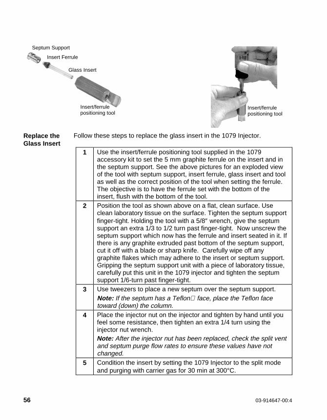
56 03-914647-00:4
Replace theGlass Insert
Follow these steps to replace the glass insert in the 1079 Injector.
1 Use the insert/ferrule positioning tool supplied in the 1079accessory kit to set the 5 mm graphite ferrule on the insert and inthe septum support. See the above pictures for an exploded viewof the tool with septum support, insert ferrule, glass insert and toolas well as the correct position of the tool when setting the ferrule.The objective is to have the ferrule set with the bottom of theinsert, flush with the bottom of the tool.
2 Position the tool as shown above on a flat, clean surface. Useclean laboratory tissue on the surface. Tighten the septum supportfinger-tight. Holding the tool with a 5/8″ wrench, give the septumsupport an extra 1/3 to 1/2 turn past finger-tight. Now unscrew theseptum support which now has the ferrule and insert seated in it. Ifthere is any graphite extruded past bottom of the septum support,cut it off with a blade or sharp knife. Carefully wipe off anygraphite flakes which may adhere to the insert or septum support.Gripping the septum support unit with a piece of laboratory tissue,carefully put this unit in the 1079 injector and tighten the septumsupport 1/6-turn past finger-tight.
3 Use tweezers to place a new septum over the septum support.Note: If the septum has a Teflon face, place the Teflon facetoward (down) the column.
4 Place the injector nut on the injector and tighten by hand until youfeel some resistance, then tighten an extra 1/4 turn using theinjector nut wrench.Note: After the injector nut has been replaced, check the split ventand septum purge flow rates to ensure these values have notchanged.
5 Condition the insert by setting the 1079 Injector to the split modeand purging with carrier gas for 30 min at 300°C.
Insert/ferrulepositioning tool
Insert/ferrulepositioning tool
Glass Insert
Insert Ferrule
Septum Support

MAINTENANCE1079 Injector
CP-3800 GC Getting Started Manual 57
Clean theGlass Insert
Glass inserts must be clean and free from sample residue and particulatematter (such as bits of septum rubber or graphite). Follow these steps toclean the glass insert in the 1079 Injector.
1 Remove the glass insert. It is safest to cool the injector and columnovens to 50°C before removing the insert.
WARNING :BURN HAZARD
Use care when removing inserts from the injector.Inserts can be at high temperatures and are likely hot.Place hot inserts on a clean glass or metal surface only.
2 To clean glass inserts, use one of the following procedures (thechoice of cleaning procedure depends upon the nature of samplesinjected):
• Rinse the inserts with solvent or soak the inserts in hot acid.
• Heat them in a glass annealing oven (to 500°C) or pass theinserts through the flame of a Bunsen burner.
• Wash in a 1:1:1 mixture of methanol:methylene chloride:hexanein an ultrasonic cleaner for 30-60 min, then dry the inserts in anoven.
Note: For the 2 mm glass wool packed glass insert, remove the glass woolby blowing compressed gas in the end of the insert. Clean the insert followingone of the procedures listed above. Repack the insert with deactivated glasswool (10-20 mg). Leave ∼1.5 cm of the bottom of the glass insert unpacked.The capillary column will be inserted in this empty space when re-installed inthe injector body.
Note: Rinsing the glass inserts with strong acids or bases or heating to ahigh temperature will remove the deactivation coating on the glass inserts.Rinsing the glass inserts with solvents or mixed solvents will not remove thedeactivation coating.

58 03-914647-00:4
Deactivatethe GlassInsert
Follow these steps to deactivate the glass insert in the 1079 Injector.
Note: This procedure can be used on all glass inserts except inserts packedwith 10% OV-101 on Chromosorb W-HP (P/N 03-918956-00). Up to threeinserts can be deactivated at a time using this procedure.
1 In a 10 mL glass graduated cylinder, add 0.5-1 mL ofdimethyldichlorosilane. Fill to 10 mL with isooctane, hexane ortoluene.
2 Cover the top of the graduated cylinder with aluminum foil and placethe cylinder in an ultrasonic bath. Sonicate for 30 sec to mix thesolution.
3 Add up to 3 inserts to the solution.
Note: Deactivate glass inserts only after they have been thoroughly cleanedusing the above procedure.
4 Sonicate the inserts in the cylinder for 10 min. Rinse the inserts 3times with 10 mL isooctane, hexane or toluene. Each rinse shouldinclude 2-3 min of sonication.
5 Add 10 mL of methanol and sonicate for 2-3 min. Decant themethanol and repeat the methanol rinse step.
6 Decant the methanol. Transfer the deactivated inserts to a smallclean glass beaker. Cover the beaker with aluminum foil and bake at200°C for 1 hour.
7 After the inserts cool to room temperature, store them in a cleanscrew cap glass vial or the original packaging.
To clean the injector body, proceed as follows:
1. Set the column oven temperature to 45°C and the 1079 injectortemperature to 50°C. Wait for the zones to reach their set temperaturesand then turn the column oven off by pressing the “TURN OVEN OFF”softkey located in the Column Oven section of the method.
2. Use the 5/16” open-end wrench to loosen the capillary column nut.
3. By hand, carefully withdraw the fused silica column and nut from theinjector assembly. Set the column nut and column end on the floor of theGC oven.

MAINTENANCE1079 Injector
CP-3800 GC Getting Started Manual 59
WAR NING:FIRE HA ZA RD
Use proper e ye and skin protection. Methanol and acetone are toxic andflammable chemicals. Exercise appropriate precautions when thesechemicals are used.
4. Remove the injector nut, septum, and septum support, with ferrule andinsert attached.
5. Moisten a cotton swab an a stick with methanol and gently swab center ofthe injector body.
6. Moisten a cotton swab on a stick with iso-octane and gently swab thecenter of the injector body.
7. Examine the end of the fused silica column to ensure that it has not beendamaged. Slide the end of the fused silica column into the opening of theinjector.
8. Gently twist the column nut in the opposite direction used to tighten thenut. Place the column nut on the end of the injector and tighten the nut.This procedure minimizes twisting the column.
9. Use the 5/16″ open-end wrench and tighten with 1/6-turn to secure thecolumn in place.
10. Replace the septum support, insert, ferrule, septum, and injector nut.
11. To check whether the injector is leak-tight, connect a flow meter to thesplit vent. Set the Relay to the split mode. If the flow meter indicates aflow less than previously measured, the injector has a leak.
12. Turn the column oven back on by pressing the “TURN OVEN ON”softkey in the column oven section of the method.

60 03-914647-00:4
1041 Injector
HardwareReplacementand CleaningProcedures
Routine cleaning and maintenance of the 1041 Universal Injector systemincludes septum replacement and column conditioning. Pressure testingand leak checking procedures are included to assure proper functioning ofthe system.
SeptumReplacement
Septum replacement represents the major part of routine chromatographicmaintenance. Septum damage from the needle penetrations can be avoidedby injecting into the same hole and not using syringes with needles havingburrs or bends at the tip which cut the septum.
The injector nut and automatic start switch assembly may bevery hot during instrument operation and should not betouched with unprotected hands. Allow sufficient time for theinjector nut and surrounding assemblies to cool beforecontinuing with this procedure.
CAUTIO NHandling a septum with bare fingers may result in columncontamination. Use tweezers, finger cots, or gloves when installinga new septum.
1 Be sure the injector nut is cool. Unscrew the injector nut and placeon a clean, uncontaminated surface.
2 Using tweezers, remove the septum, taking care not to scratch theinternal surfaces of the injector.
3 Using tweezers, place a new high temperature septum in theinjector. If the septum is TFE or FEP coated put that side down.
4 Replace the injector nut and tighten until resistance is felt, thentighten an extra 1/2 to full turn.

MAINTENANCE1041 Injector
CP-3800 GC Getting Started Manual 61
Figure 4 1041 Injector Assembly
Needle/SyringeCleaning
For normal use, rinse the needle/syringe by slowly drawing up and quicklyexpelling solvent or the next sample to be used. Repeat the process severaltimes.
Note: When rinsing with the next sample, DO NOT expel sample back intothe sample container.
1 Septum Nut2 Automatic Start Switch3 Septum, 10 mm4 Injector Body5 Injector Insert6 Capillary Nut
1
23
4
5
6

62 03-914647-00:4
LeakChecking
Leak checking methods used with the 1041 Universal Injector are presentedin order of overall sensitivity and performance. When leak checking theinjector only, be sure to use the appropriate procedure.
1 Remove the test column and plug the injector outlet with a 1/16″ no-hole ferrule (P/N 28-694503-00). Remove the injector nut, install anew septum, then replace injector nut and turn nut clockwise until itcomes to a stop.
2 Pressurize the injector to 60 psig with carrier gas. Turn off the carriergas flow at the supply.
3 A pressure drop less than or equal to 1/2 psig in 15 minutes isacceptable. Locate leaks with an appropriate leak detector.Note: Any changes in temperature while performing this test mayresult in false readings due to expansion/contraction of the gas withtemperature.
CAUTIO NCommercial soap type leak detection fluids should not be usedat any point in a capillary system, since, if a leak is present, thefluid will penetrate and contaminate the system. Columnperformance will be degraded and a substantial period of timemay be required to achieve a clean system.
4 An alternate way to leak check the injector only is to have the columninstalled in the injector end and the opposite column end sealed witha flame or appropriate fitting.

MAINTENANCE1041 Injector
CP-3800 GC Getting Started Manual 63
Gas LeakChecking
A convenient and non-contaminating way to leak test fittings and connectionsafter installation or hardware replacement procedures is to direct a small jetof gas (butane from a disposable lighter recommended for flame ionizationdetectors) at the point to be tested, then use the detector, at maximumsensitivity, to detect leakage of gas into the system. Use normal column flow,a cool oven, and an operational detector. If a peak is detected in excess ofthe magnitude given in the following table, repair the leak.
Detector GasAttenuation,
RangeMaximumPeak Size
FID Butane 16 x 10-12 30%
ECD Dichloromethane 2 x 1 50%
PFPD, Sulfur Mode Natural Gas containingmethanethiol
2 x 10⁻¹⁰ 50%
TSD Dichloromethane 2 x 10-12 2%
Visual LeakChecking
The least preferred method of leak checking is to place a drop of puresolvent (isopropyl alcohol recommended) on the suspected fitting orconnection and look for bubbles.
CAUTIO NCommercial soap type leak detection fluids should not be used atany point in a capillary system, since, if a leak is present, the fluidwill penetrate and contaminate the system. Column performancewill be degraded and a substantial period of time may berequired to achieve a clean system.
Syringe LeakChecking
In some instances, non-reproducible chromatographic responses can beattributed to a worn and/or leaky syringe. The syringe must be leak tight. Tocheck the syringe, insert the needle in an injector operating at 20 to 30 psigwith a no-hole ferrule. Place a drop of solvent at suspect leak locations andlook for bubbles.

64 03-914647-00:4
1061 Injector
The 1061 is mechanically similar to the 1041 except that it uses a glass insertfor flash vaporization injection. Follow the same maintenance procedures forthe 1061 that are outlined above for the 1041, except in the case of changingor cleaning glass inserts.
Replacingthe 1061Glass Insert
After prolonged use, the 1061 glass insert may need to be removed forcleaning purposes or to be replaced with a new insert. Note that there are twodifferent glass inserts, one for use with large-bore (0.53 mm ID) capillarycolumns and one for use with packed columns. These inserts are notinterchangeable.
• Large-bore glass insert, Part Number: 03-918339-00
• Packed column glass insert, Part Number: 37-000813-00
Refer to the figure below when replacing the glass insert.
Figure 5 1061 Injector Assembly
1 Septum Nut2 Automatic Start Switch3 Septum, 10 mm4 Injector Insert5 Injector Body
These tools are needed to replace the glass insert:
• Tweezers or septum pick (P/N 72-000084-00)
• Injector nut wrench (P/N 03-908423-00)
• Clean laboratory tissue
1
2
3
4
5

MAINTENANCE1061 Injector
CP-3800 GC Getting Started Manual 65
Remove theGlass Insert
Follow these steps to remove the glass insert from the 1061 Injector.
1 Use the injector nut wrench to remove the injector nut (Item 1). Placethe nut on a clean surface (e.g., clean tissue).
WARNING :BURN HAZARD
The injector nut may be hot. Lower the injectortemperature to 50 °C and permit the injector nut to coolbefore proceeding.
Note: If the GC is equipped with an 8200 AutoSampler, push the carrouselrelease button and swing the carrousel out to access the injector nut.
2 With tweezers or a septum pick, lift the edge of the septum. Removethe septum.Note: Replace the injector septum each time the glass insert isreplaced.
3 Use tweezers to grasp the glass insert and remove it from theinjector.Note: The glass inserts can be cleaned and reused.
Replace theGlass Insert
Follow these steps to replace the glass insert in the 1061 Injector.
1 Pick up the new insert with tweezers and place it in the injectorcarefully.
2 Use tweezers to place a new septum in the injector.Note: If the septum has a Teflon face, place the Teflon face toward(down) the column.
3 Place the injector nut on the injector and tighten by hand until youfeel some resistance, then tighten an extra 1/2 to full turn using theinjector nut wrench.Note: After the injector nut has been replaced check the headpressure (EFC status on display or manual pressure gauge onpneumatics panel) increases to its normal value. If this does nothappen there is an indication of a leak.
4 Condition the insert by setting the 1061 Injector temperature to300°C and allowing the system condition for 30 minutes.

66 03-914647-00:4
Clean theGlass Insert
Glass inserts must be clean and free from sample residue and particulatematter (such as bits of septum rubber or graphite). Follow these steps toclean the glass insert of the 1061 Injector.
1 Remove the glass insert. It is safest to cool the injector to 50°Cbefore removing the insert.
WARNING :BURN HAZARD
Use care when removing inserts from the injector.Inserts can be at high temperatures and are likely hot.Place hot inserts on a clean glass or metal surface only.
2 To clean glass inserts, use one of the following procedures (thechoice of cleaning procedure depends upon the nature of samplesinjected):• Rinsing the inserts with solvent or soaking the inserts in hot acid.
• Heating them in a glass annealing oven (to 500°C) or passingthe inserts through the flame of a Bunsen burner.
• Wash in a 1:1:1 mixture of methanol:methylene chloride:hexanein an ultrasonic cleaner for 30-60 min, then dry the inserts in anoven.

MAINTENANCE1061 Injector
CP-3800 GC Getting Started Manual 67
Deactivatethe glassinsert
Follow these steps to deactivate the glass insert in the 1061 Injector.
1 In a 10 mL glass graduated cylinder, add 0.5-1 mL ofdimethyldichlorosilane. Fill to 10 mL with isooctane, hexane ortoluene.
2 Cover the top of the graduated cylinder with aluminum foil and placethe cylinder in an ultrasonic bath. Sonicate for 30 sec to mix thesolution.
3 Add up to 2 inserts to the solution.Note: Deactivate glass inserts only after they have been thoroughlycleaned using the above procedure.
4 Sonicate the inserts in the cylinder for 10 min. Rinse the inserts 3times with 10 mL isooctane, hexane or toluene. Each rinse shouldinclude 2-3 min of sonication.
5 Add 10 mL of methanol and sonicate for 2-3 min. Decant themethanol and repeat the methanol rinse step.
6 Decant the methanol. Transfer the deactivated inserts to a smallclean glass beaker. Cover the beaker with aluminum foil and bake at200°C for 1 hour.
7 After the inserts cool to room temperature, store them in a cleanscrew cap glass vial or the original packaging.

68 03-914647-00:4
Flame Ionization Detector
When the performance of the FID has degraded you may want to replace theflame tip ferrule, or clean the deposits from the internal parts, including theflame tip.
Clean theFlame Tipand InternalParts
If the FID noise increases with frequent spikes, the internal parts may befouled and need to be cleaned.
To clean the flame tip and the internal parts of the FID, proceed as follows:
Note: Always handle detector components with tweezers to avoidcontamination.
WARNING:EYE HAZARD
WARNING:FIRE HAZARD
Use proper eye and skin protection.Methanol and acetone are toxic andflammable chemicals. Exercise appropriatecare when you use and dispose of thesesubstances.
1 Remove the detector and internal parts.
2 Scrape the deposits from the bore of the collector tube, the insulator,and the metal part of the flame tip with emery cloth (e.g., SiO2).
3 If the flame tip is plugged, insert a wire through the flame tip orifice toclear it.
4 If you have access to an ultrasonic cleaner, clean the collector,insulator, and flame tip with distilled water.
5 Rinse the cleaned components with methanol or acetone and air dry.
6 Wipe the detector tower with acetone.
7 Clean the probe arms with methanol and air dry or dry in an air oven(maximum drying temperature of 150°C).
8 Reinstall the detector. To prevent leaks, use a NEW aluminum sealwasher each time you install the detector tower.

MAINTENANCEFlame Ionization Detector
CP-3800 GC Getting Started Manual 69
Figure 6 Flame Ionization Detector Assembly
Replace theFerrule
After a period of prolonged use, the flame-tip ferrule may deteriorate andcrack. As a consequence, a leak may develop around the base of the flametip assembly that causes unstable baseline noise and reduced sensitivity. Inthis situation, or when the detector is to be operated at temperatures above350°C, you must replace the ferrule. Be sure to select the proper ferrule forthe application. The Vespel/graphite ferrule has a maximum temperature limitof 350°C.
1 Signal Cable2 Signal Probe3 Ignitor Cable4 Ignitor Probe5 Collector6 Ceramic Insulator7 FID Tower8 Flame Tip9 Aluminum Crunch Washer10 Detector Base11 Column Ferrule12 Column Nut
1
2
5
63
4
7
8
9
11
10
12

70 03-914647-00:4
Thermionic Specific Detector
Cleaning/Maintenance
When the TSD exhibits low sensitivity or high background noise,cleaning is indicated. Visual inspection may also indicate a need forcleaning. The ceramic bead, collector, or flame tip are all parts that aredeposit prone, depending on the type of samples being used. Cleanthese parts as indicated in the following paragraphs.
Note: Always handle detector components with tweezers to avoidcontamination.
Bead Cleaning Non-volatile deposits can be removed from the bead by gently scrapingthe bead surface with a sharp tool or abrasive paper. The bead shouldbe supported while being cleaned to prevent bending the lead andcracking the ceramic coating on the leads.
Flame Tip andInternal PartsCleaning
Follow the steps below to clean the flame tip and internal parts.
WARNING:EYE HAZARD
WARNING:FIRE HAZARD
Use proper eye and skin protection.Methanol and acetone are toxic andflammable chemicals. Exercise appropriateprecautions when these chemicals are used.
1 Remove the detector and internal parts. Handle internal partswith tweezers and place on a clean, uncontaminated surface.
2 Clean deposits from the surface of the collector with water orabrasive paper.
3 Remove deposits which form on top of the flame tip byscraping. If flame tip is plugged, clear by inserting wire(approximately 0.012 inch diameter) into flame tip orifice.
4 Flush cleaned components with methanol and air dry.
FerruleReplacement
If a leak develops around the base of the flame tip assembly due to adeteriorated ferrule or if the detector is to be operated at temperaturesabove 350°C, and results in a crack, the ferrule must be replaced. Aleak at the ferrule may cause noise, instability, and loss of sensitivity.Be sure to select the proper ferrule for the application. The Vespelferrule has a maximum temperature limit of 350°C.

MAINTENANCEThermionic Specific Detector
CP-3800 GC Getting Started Manual 71
Figure 7 Thermionic Specific Detector Assembly
1 Signal Cable2 Signal Probe3 Bead Supply Cable4 Bead Probe5. Ceramic Bead6 Collector7 Ceramic Insulators8 TSD Tower9 Flame Tip10 Aluminum Crunch Washer11 Detector Base12 Column Ferrule13 Column Nut
6
10
7
8
12
9
13
1
23
4
5

72 03-914647-00:4
Electron Capture Detector
Chemical contaminants may deposit on the components of the detectorassembly as the ECD is operated. In many cases, you can removecontaminants deposited on the radioactive foil or cell ceramic insulators byheating.
Refer to the Radiation Safety Manual (P/N 03-913999-00) for detector repair,radioactive decontamination, foil replacement, and leak-test information.
Note: Although all heated zones on the 3800 have a potential uppertemperature of 450°C, Varian recommends that you do not operate the ECDabove 420°C. (The radioactive source temperature is less than 400°C evenwhen the detector set temperature is 450°C.)
ThermalCleaningWithCarrierGas
Use N2 or Ar/CH4 as the carrier gas to thermally clean the ECD. Refer to Table 2on page 39 for flow rates.
1 With carrier gas and makeup gas flowing through the ECDcell, increase the DETECTOR TEMP to 400°C.
WARNING:RADIATION SOURCE
Do not attempt to chemically clean the source. Submerging the cell in liquid or runninga liquid through the cell will cause radioactivity to migrate, contaminate the exterior ofthe cell, and damage the insulators. The cleaning of the radioactive ECD source can byperformed only by an NRC licensee. Cleaning of the ECD source by persons other thanregistered NRC licensees is strictly forbidden by law.
CAUTIO NAVOID FOIL DAMAGE. The carrier gas must be flowing throughthe detector cell before setting the DETECTOR TEMP above roomtemperature. Failure to do so may damage the radioactive foil,which is not covered by warranty.

MAINTENANCEThermal Conductivity Detector
CP-3800 GC Getting Started Manual 73
2 Monitor the output signal while the detector heats to itsmaximum temperature. The signal will increase initially, thengradually decrease as chemical contaminants vaporize fromthe detector surfaces.
3 Allow the DETECTOR TEMP to remain at 400°C until the signalreaches a stable level. A stable signal indicates that the foil hasbeen cleaned as much as it can be by this method.
4 Set the detector at normal operating temperatures and flowcarrier gas through the detector overnight. Check and readjustthe Contact Potential setting if necessary.
5 If the performance of the detector is not restored by thesecleaning methods, refer to the Radiation Safety Manual(P/N 03-913999-00) for information on replacement of the foil.
Thermal Conducti vity Detector
The Thermal Conductivity Detector is not user serviceable and has noreplacement parts. To condition the TCD, set the detector temperature to350°C and allow it condition for 4 hours or overnight. The filamenttemperature should be set to zero during this procedure.
Pulsed Flame Photometric Detector
For PFPD maintenance procedures see the PFPD Operator’s Manual,P/N 03-914649-00.
Micro Thermal Conducti vity Detector
The Micro-TCD is not user serviceable and has no replacement parts.

CP-3800 GC Getting Started Manual 75
Parts and Supplies
To OrderParts andSupplies …
• In the USA and Canada, call 1-800-926-3000.
• In Europe, call your local Country office.
• In the rest of the world, call your local Varian representative
• Or, contact Varian on the Internet at http://www.varian.com
Injectors
1079 InjectorDescription Part NumberCeramic scoring wafer (for cutting fused silica columns) 01-900158-00Capillary column nut 03-949551-00Ferrule, no hole (package of 10) 28-694503-01Septum pick 72-000084-00Graphite ferrule for insert, 5 mm (package of 2) 03-925342-02Open 0.5 mm ID insert 03-925331-00SPME open insert 0.8 mm ID 03-925330-00Splitless insert, 2 mm ID 03-918466-00Splitless insert, packed with deactivated glass wool, 2 mm ID 03-925350-00Split insert, fritted, 3.4 mm ID 03-918464-01Split insert, open, 3.4 mm ID 03-918464-00Split insert, packed with 10% OV-101 on Chromosorb W-HP 03-918956-00Septa (package of 25), 11 mm 00-997630-02Septum support 03-918676-00Insert/Ferrule positioning tool 03-925385-00
Options
Capillary Column Quick Connect Kit 03-925751-91
3800 Field kit, LCO2 Cryo Kit 03-925513-91
3800 Field kit, LN2 Cryo Kit 03-925506-91
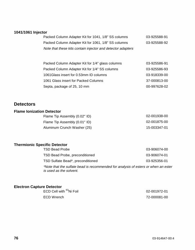
76 03-914647-00:4
1041/1061 InjectorPacked Column Adapter Kit for 1041, 1/8” SS columns 03-925588-91
Packed Column Adapter Kit for 1061, 1/8” SS columns 03-925588-92
Note that these kits contain injector and detector adapters
Packed Column Adapter Kit for 1/4” glass columns 03-925586-91
Packed Column Adapter Kit for 1/4” SS columns 03-925586-93
1061Glass insert for 0.53mm ID columns 03-918339-00
1061 Glass insert for Packed Columns 37-000813-00
Septa, package of 25, 10 mm 00-997628-02
Detectors
Flame Ionization DetectorFlame Tip Assembly (0.02″ ID) 02-001938-00
Flame Tip Assembly (0.01″ ID) 02-001875-00
Aluminum Crunch Washer (25) 15-003347-01
Thermionic Specific DetectorTSD Bead Probe 03-906074-00
TSD Bead Probe, preconditioned 03-906074-01
TSD Sulfate Bead*, preconditioned 03-925356-01
*Note that the sulfate bead is recommended for analysis of esters or when an esteris used as the solvent.
Electron Capture DetectorECD Cell with 63Ni Foil 02-001972-01
ECD Wrench 72-000081-00

PARTS AND SUPPLIESDetectors
CP-3800 GC Getting Started Manual 77
Thermal Conductivit y DetectorTCD Make-up Gas Option 03-925605-01
Pulsed Flame Photometric DetectorAluminum Crunch Washer 15-003347-00
Combustor, Quartz (2mm ID) 03-925176-00
Combustor, Quartz (3 mm ID) 03-925177-00
Filter Assembly, Sulfur 03-925151-01
Filter Assembly, Phosphorus 03-925151-02
Ignitor Assembly 03-925160-00
Combustor support, 2 mm 03-925178-00
Combustor support, 3 mm 03-925179-00
Combustor support seal 03-925138-00
Micro-TCDFerrule, 0.25 mm ID CP85888
Ferrule, 0.4 mm ID CP85889
Ferrule, 0.5 mm ID CP470100
Ferrule, 0.8 mm ID CP470101