course unit - ergocad
TRANSCRIPT

Version 14
COURSE UNIT
Quantities

Evaluation
www.elitecad.eu 2
TABLE OF CONTENTS
COURSE UNIT ........................................................................................................................ 1
TABLE OF CONTENTS .......................................................................................................... 2
1. Course unit - Evaluation ..................................................................................... 3
2. Evaluation database .......................................................................................... 17
3. Areas and standards ......................................................................................... 18
4. Room finishes .................................................................................................... 48
5. Construction parts ............................................................................................. 67
6. Adding additional properties .......................................................................... 111
7. Defining 3D objects as a construction part................................................... 113
8. Control functions ............................................................................................. 127
9. Evaluation ...................................................................................................... 9-135
10. Evaluation options and lists ........................................................................... 138
11. Examples .......................................................................................................... 166

EVALUATION COURSE UNIT
www.eliecad.eu 3
1. Course unit - Evaluation
Recommendation
To learn how Evaluation functions, it is recommended that you first study Chapters 1.1 to 1.5.
EliteCAD Version
Minimum requirement for this course unit: EliteCAD ARCHITECTURE Version 13. The version can be checked using the “?” > Info menu. This menu can also be used to load an internet update.
Project for evaluation
When EliteCAD AR13 is installed, sample projects are imported. The sample project for evaluation is called CAD_Object_Evaluation.
1.1 Innovations for EliteCAD AR13
Multi-layer floors (slabs), roofs and floorings
Four layers:
Load-bearing
Non load-bearing
Subconstruction
Facing
Automatic layer type management using synonyms
New height definition functionality for calculations of living space
System-built wall (all layers evaluated together)
Hierarchical structuring type in quantities manager. Living space allocated to room.
Property “Description” and in later updates “Type”
Evaluation lists structured by layer types and system-built walls
Living space verification in graph format and as a list
New lists for the following construction parts: o Suspended ceilings (hollow ceiling) o Banisters o Internal and external windowsills (Switzerland: window ledges and windowsills) o Free objects
Available in later updates: o ÖNORM B 1800 issued 2011 o EN 15221-6 Area and space measurement in Facility Management o Verification of gross floor area (Brutto-Raumhalt, BRI) or building volume (Gebäudevolumen, GV)

EVALUATION COURSE UNIT
www.eliecad.eu 4
1.2 Evaluation - method of function
Overview
Construction parts, rooms and floors are objects. These are broken down for evaluation into object types (e.g. floor data). For the object types, the various properties are evaluated. Construction part layers are divided up into layer types (e.g. facing). These are evaluated as object types (e.g. wall facing). The layer type is set by the choice of material, automatically or manually. For walls, the choice of materials automatically determines the trades. For wall openings, a deduction audit is carried out in accordance with the regulations. In the same room, wall coverings may be of varying thicknesses. The depth of a wall covering on different base materials can be preset (e.g. thickness 0 on a plasterboard base)
Objects and object types Extensive information can be found in the Manual and in Chapter 9.3 Object types. Short summary:
Objects Objects are individual drawing elements such as construction parts, which can be selected in the CAD using a single click.
Object types Object types are listed in quantities manager. Object types map the calculation results for the evaluation.
Object types without reference to an individual object
The floor data object type contains floor calculations such as floor area and volume. The external surface object type corresponds to the surface of the external wall on the perimeter contour. The object type is displayed by selecting it in quantities manager.
Object types with reference to an individual object
All construction parts, library parts etc. can be displayed by selecting the object type in quantities manager.

EVALUATION COURSE UNIT
www.eliecad.eu 5
Objects with several object types
Rooms
Room finishes and living space are subordinate to rooms. Room finishes are broken down into covering finishes and the layers underneath. The layer type (illustration: facing) is set automatically by concatenation with the material
Multilayer construction parts and layer types
With multilayer construction parts, several object types are calculated.
Each layer belongs to one layer type (e.g. subconstruction)
Layers in the same layer type are grouped and measured together, if they touch one another and are of the same size.
In addition, each layer is also measured individually.
The main object type includes all layers (e.g. wall).
For walls, facings are measured on the surface, while the other layer types are measured in the centre of the layer(s).

EVALUATION COURSE UNIT
www.eliecad.eu 6
1.3 Diagram: Management using materials
?
Oberbegriff
?
?
Gewerk
?
?
Abzugs-Prüfung
?
?
Montagewand
?
?
Schichtart
?
?
Putzdicke
?

EVALUATION COURSE UNIT
www.eliecad.eu 7
Settings
Quantities manager
Toolbar *Construction parts
Extras menu > Evaluation > Quantities manager
Toolbar > Evaluation > Quantities manager
Rules/Configuration
Synonyms for materials The synonyms are the central element in EliteCAD and BIM2COST for managing:
Setting the layer type for multilayer construction parts
Trades or work type and deduction audit
Plaster thicknesses on wall sub-bases for calculations of net room area for living spaces and floor plan areas.
Attribution rules to cost components in BIM2COST Function: The materials (synonyms) are subordinated to an overarching term which is used in the model. The settings are managed in the other registers using the overarching term. Important: The program is case-sensitive. The ‘ß’ character, which is only used in Germany and Austria, can cause problems. For that reason, all terms are listed using the spelling which is standard in Switzerland.
Layer type Using the layer type, it is possible to measure layers grouped together.
Presetting the layer type
In the parameter mask, the layer type is automatically preset for all construction parts, with the lock in the closed position.
Load-bearing
Non load-bearing
Subconstruction
Facing The lock is only opened if the presetting does not reflect the standard setting. In BIM2COST, the layer type is changed in the layer editor using the codes K, N, U and B. Example: A sand-lime wall can be either load-bearing (presetting) or non load-bearing.

EVALUATION COURSE UNIT
www.eliecad.eu 8
Register of layer types
The overarching terms in the registers for layer types (e.g. load-bearing) are entered in the register of layer types for walls, foundations, slabs, roof and floor. After this, the layer type is automatically preset in the construction part parameter masks, with the lock closed.
Layer type evaluation
Joint evaluation
Where several adjoining layer types belong to the same layer type and where these have the same dimensions, they are evaluated together. Example: On a roof, the tile battening and the counter battening are evaluated together as a subconstruction.
Layer type evaluation Wall
Facings and system-built walls are always evaluated using the wall surface. The other layer types are evaluated using the middle of all layers.
Object types for layer types
For all construction parts, the four layer types can be preset in the parameter mask (lock in closed position). For floors, when defining spaces the layer types load-bearing and non load-bearing are not available.
Load-bearing
Non load-bearing
Subconstruction
Facing

EVALUATION COURSE UNIT
www.eliecad.eu 9
The naming of the object type in quantities manager deviates from the settings descriptions above, for better comprehensibility. The naming of the object types can be influenced via Settings > Texts > Object types.
Overview of object types and layer types
Wall Object type
Load-bearing Wall construction
Non load-bearing Wall construction, non-bearing
Subconstruction Wall facing subconstruction
Facing Wall (facing)
Slab, internal + external foundation
Object type
Load-bearing Floor construction
Non load-bearing Floor construction, non-bearing
Subconstruction Floor subconstruction
Facing Floor facing
Foundation Object type
Load-bearing Foundation construction
Non load-bearing Foundation subfloor
Subconstruction Socket concrete
Facing Foundation insulation
Roof Object type
Load-bearing Roof construction
Non load-bearing Roof insulation
Subconstruction Roof subconstruction
Facing Roof skin and soffit
Hollow ceiling Object type
Load-bearing Ceiling facing subconstruction
Non load-bearing Ceiling facing subconstruction
Subconstruction Ceiling facing subconstruction
Facing Ceiling facing
Floor finish - Room Object type
Subconstruction Floor finish sublayer
Facing Floor covering finish
Wall finish - Room Object type
Subconstruction Wall finish sublayer *)
Facing Wall covering finish *) Only in BIM2COST
Ceiling finish - Room Object type
Subconstruction Ceiling finish sublayer *)
Facing Ceiling covering finish *) Only in BIM2COST
Layer type preset for IFC imports
When importing IFC models, the layer type is automatically adopted based on the presets

EVALUATION COURSE UNIT
www.eliecad.eu 10
Materials and trades setting in EliteCAD The choice of materials for construction parts triggers automatic allocation to the trades or craft type in some cases.
Materials and trades/craft type for CAD floors
Concrete materials Concrete ceiling
Other materials without trades/work type
Materials and trades/work type for CAD roofs
Concrete materials Concrete ceiling
Other materials without trades/work type
Materials and trades/work type for walls
Concrete materials Concrete walls
Brick materials: Brick walls
Plaster etc. Dry-type construction
External insulation materials External insulation
Other materials without trades/work type
Setting for trades or work type
Quantities manager > Rules/Configuration
Example Select index of object types Select masonry index Here, all materials can be listed which are intended to belong to the trade “Brick walls”. Overarching terms are selected here for materials. Sub-terms (synonyms): see next section. The listing can be amended using the buttons Remove and Add. The materials listed in the in-situ concrete construction index are also applicable for CAD floors For detailed explanations, refer to Options Walls (Chapter 10.3)
Deduction audits for trades
In the options, the values for the deduction audits are entered for walls and wall finishes (plaster):
Brick walls
Concrete walls
Drywalls
External insulation. The deductions for the materials listed in the “Other layers” index are checked using the value for brick walls. For non-listed materials, measured values are used.

EVALUATION COURSE UNIT
www.eliecad.eu 11
System-built walls The system-built wall option has the effect of evaluating all layers in a wall together. The measurement is taken on the surface of the wall, on the side of the wall axis drawn.
Use of the system-built wall option
Partition walls drywall construction
Prefabricated walls
Walls in element construction. It must be remembered that all materials are assigned to either the same trade or none.

EVALUATION COURSE UNIT
www.eliecad.eu 12
Different wall finish thicknesses for living areas In EliteCAD AR13, the user can select whether different wall finish thicknesses are to be calculated for different wall materials for the clear areas, e.g. for the calculation of living space. These settings are then applicable for all rooms created with this option.
Setting for wall finish thicknesses
Quantities manager > Rules/Configuration
The wall materials are entered on the list using the Add button. The nominal thickness of the wall finish on the wall material base is set in the ‘Plaster depth’ column (depending on the CAD setting). Next, with the lock in the closed position, the finish thickness on the predefined wall materials is calculated in accordance with this preset. On the wall bases not listed above, the greyed value is included in the finish thickness calculation. The calculated living space can be viewed in quantities manager. This object type is subordinated to the room.

EVALUATION COURSE UNIT
www.eliecad.eu 13
Special materials (insulation, etc.) Allows for special materials to be included for various trades and layer types. However, in order for these to be differentiated, they must be specified more accurately through naming.
Insulation for trades
Insulation for walls
All wall insulations without special descriptions are assigned to the ‘Brick walls’ trade Layer type subconstruction
Insulation for roofs and ceilings
Layer type non load-bearing. (For better differentiation from the other subconstruction, such as laths, etc., since the surface to the subconstruction is widely varying).
Insulation for foundations
Layer type facing
Insulation for floors
Layer type subconstruction
Insulation - beams
Insulation located in the bearing construction layer Layer type bearing construction
External insulation
Only rendered external insulation. Trade external insulation Layer type facing
Insulation - facade construction and insulation laths
For back-ventilated facade facings Layer type subconstruction
Drywall construction insulation
Insulation for walls in drywall construction, e.g. plasterboard partition walls. Trade drywall construction Layer type facing
Partition wall insulation and timber partition insulation
Insulating layers in the load-bearing construction layer of timber walls. Layer type bearing construction.
Gypsum fibre board
To distinguish from gypsum plaster board as a single overarching term.

EVALUATION COURSE UNIT
www.eliecad.eu 14
Gypsum fibre boards are generally used in timber construction, for which reason this material is not assigned to drywall construction.
Timber
This term should be avoided for spatial construction parts such as slabs, roofs, walls etc.
Timber facing
Layer type facing. If the timber formwork is a subconstruction, this must be set as such (lock in the open position). On timber construction ceilings, for better differentiation the roof boarding above the beam should be described as a dead floor.
Timber construction system
Panel construction using non-solid panels (e.g. partition construction) Layer type bearing construction Allocation in BIM2COST to cost component element construction in timber
Timber construction system - solid wood
Element construction using solid wood elements (e.g. log wall) Layer type bearing construction Allocation in BIM2COST to cost component solid timber walls
Glued laminated timber and glued cross-laminate timber
Load-bearing layers in timber construction Layer type bearing construction Allocation in BIM2COST to cost component solid timber walls
Timber box panels and timber ribbed panels
Layer type bearing construction
Timber materials
Excluding wood fibre board, but including laminated timber (not glued cross-laminated timber) Layer type subconstruction
Wood fibre boards
Layer type subconstruction
Dead floor
Upper subconstruction for slabs

EVALUATION COURSE UNIT
www.eliecad.eu 15
1.4 Preparation and evaluation
Reading in the model
Select the project CAD_Object_Evaluation. There are different standards and materials for each country. Accordingly, for this course unit there is a separate model for each country. The following should be imported: Switzerland: Model_Evaluation_CH.d Germany: Model_Evaluation_DE.d Austria: Model_Evaluation_AT.d
Preparing the model
Perform an AR object refresh for each storey. The refresh should not be carried out for the course model. This prevents hatchings for materials from being lost.
Quantities manager
Toolbar *Create new AR objects
Extras menu > Evaluation > Quantities manager
Toolbar > Evaluation > Quantities manager
If a list is present in the opened quantities manager, then the model has already been evaluated (see illustration). Evaluated models can be deleted in Project Management(Chapter 10).
Evaluating models
Menu Extras > Evaluation > Evaluation in DB
Toolbar Evaluation > Evaluation in DB
Quantities manager > Evaluation in DB
Lists Detailed information can be found in Chapter 10Evaluation options and lists Walls, slabs and roofs are assigned to a trade or to work type, based on the material, for the evaluation. There is a separate list for each trade or each work type. The deduction audits are taken into account in EliteCAD in accordance with the specifications in the standards. No deduction audit is carried out in BIM2COST, since the eBKP-H standard does not recognize deduction audits.

EVALUATION COURSE UNIT
www.eliecad.eu 16
1.5 Selection and display
Display When a storey is selected in quantities manager, it is displayed in solid mode. The structure is similarly displayed in solid mode. When an object is selected in the CAD, this is emphasized in the CAD and the display switches to transparency mode. In quantities manager, all object types belonging to the CAD object are marked. If an object type is selected in quantities manager, this is displayed in accordance with Options Colours (Chapter10) in the CAD. The rest of the model switches to transparency mode. The results are viewable in quantities manager in the indexes “values and attributes” and “formulae”.

EVALUATION DATABASE
www.elitecad.eu 17
2. Evaluation database
EliteCAD AR13 and BIM2COST 13 The evaluation is carried out in a MySQL database. EliteCAD and BIM2COST in the same version must be managed via the same MySQL server (this is prompted on installation). The MySQL server controls various databases. The texture database (material) is used by both programs. BIM2COST 13 and EliteCAD AR13 have different evaluation databases: DB EliteCAD AR13: rmi_cad_calc_ar DB BIM2COST: rmi_cad_calc_b2c + ekg00001 DB standard values EliteCAD AR13: ar_std_param DB cost breakdown eBKP-H BIM2COST: ekg00001
Requirement
Different MySQL servers for different versions
The same MySQL server for EliteCAD and BIM2COST in the same version
A different MySQL server must already be (or needs to be) installed for construction admin.
Note Messerli-Bauad and BIM2COST
Messerli-Bauad uses a separate MySQL server. In BIM2COST, the cost type breakdown (KAG) eBKP-H is used from this database. Thus changes to this catalogue are to be carried out in Messerli-Bauad. Without Messerli-Bauad, the cost type breakdown (KAG) eBKP-H from the EliteCAD database is used. The evaluation in BIM2COST is always carried out in the EliteCAD database (corresponds to the BIM2COST database). The quantities assigned via the allocation rules are then transferred to the Messerli-Bauad database.
Reports
For the lists in EliteCAD AR13 and BIM2COST, the databases belonging to the programs from the MySQL server for EliteCAD are used.
Modifications in BIM2COST Modifications in BIM2COST are not written to the model, but to the MySQL database. Modifications are retained and do not need to be repeated for each session.

EVALUATION ROOM DEFINITION + STANDARDS
www.elitecad.eu Areas18
Input screen Austria + Switzerland Input screen Germany
3. Areas and standards
Overview
Rooms Rooms are formed by room-dividing construction parts. Room definitions must be set into the rooms in order to enable differentiation of areas between storeys and rooms.
Room area
The room area is the net area. The room area is calculated excluding door niches and, depending on the standard, excluding window niches.
Living space
The living space corresponds to an assessed area. The assessment is undertaken in accordance with the standards.
Floor covering area
The floor covering area corresponds to the area which has a floor covering.
Floor covering in EliteCAD
The floor covering can be adjusted in EliteCAD.
Room group Various rooms can be totalled together using the room group stamp.
Storey area The storey area is the total of the room areas and the construction area. The storey area is divided internally and externally.
Perimeter contour
EliteCAD calculates the storey area using a perimeter contour. The perimeter contour encloses all room-dividing elements. The division into internal/external must be carried out manually.
Room volume
Storey height (volume)
The height of a storey is calculated using the difference between the lower edges of storey and level floors or the upper edge of the roof.
Net room height (volume)
The height of a room is calculated using the upper edge of the floor covering and the lower edge of the storey floor, level floor, hollow ceiling, roof and height definition.

EVALUATION ROOM DEFINITION + STANDARDS
www.elitecad.eu Areas19
3.1 Room definition
Standards, living spaces and areas
Red for border, number and fill: Only for areas and volumes (DIN277, ÖNORM B1800 und SIA416)
Blue for border, number and fill: Only for living spaces
Red for border and number, blue fill: For living spaces, areas and volumes (DIN277, ÖNORMB1800 and SIA416)

EVALUATION ROOM DEFINITION + STANDARDS
www.elitecad.eu Areas20
Labels For the 4 lower fields, the following attributes can be selected.
These can be selected using the button
areanorm Evaluated living space incl. height check and percentage deduction for plaster
areanormnew Evaluated living space incl. height check and measured deduction for plaster
areanorm0 Evaluated living space from living space calculation below limit height 1
areanorm50 Evaluated living space from living space calculation between limit height 1 and limit height 2
areanorm100 Evaluated living space from living space calculation above limit height 2
use Net storey area type (NGF, Nettogeschossfläche)
areatype Area (a, b or c in accordance with DIN 277 and ÖNORM B1800)
areapercent Living space percentage (%)
putzabzug (plaster deduction)
Percentage deduction for plaster in living space calculation (in accordance with the old Second German Calculation Ordinance)
volume Room volume NRI
No longer supported:
areanorm1 Room area under limit height (DIN277: 1.50 m, old standard)
areanorm2 Room area over limit height (DIN277: 1.50 m, old standard)
The Calculated Values are written into the drawing, depending on Settings > Options > Work parameters > Architecture with the option “Immediately update rooms”. If this is not enabled, then the value is only written to the drawing after “Evaluation in DB”.

EVALUATION ROOM DEFINITION + STANDARDS
www.elitecad.eu Areas21
3.2 Room definition, overview
Name (room name) EliteCAD AR13 and BIM2COST: Rooms without room
definitions are not evaluated.
In BIM2COST there is an allocation rule for room names kitchen and synonyms to cost component G 5.2. Fitted kitchen
Minimum room size in EliteCAD AR13 Quantities manager > Rules/configuration > Options In BIM2COST: Regulations > Master data > Options For “trades” shell, room, set minimum room size to 1 Closets are not listed in the reports.
Regardless of the room size, it is possible to select “Construction area” in Area type, with the effect that it isnot
listed in any report.
For air spaces, the Area type “air space” must be selected.
Unit Room group name for units, shop areas, etc.
Term for room groups in reports: UNIT.
Terms can be changed for all reports. See Text changes in lists (Chapter 10.2).
The name for each room group needs to be unique. In the reports, the rooms are sorted by room groups and the results totalled together.
Section The name of the section is exported to the room register, but is not listed in the reports.
Number Room number

EVALUATION ROOM DEFINITION + STANDARDS
www.elitecad.eu Areas22
Use type. Attribute for use Use type (not Germany) Area type (Germany) Only for areas and volumes The use type is saved in the database ar_std_param specific to the country and region. These can be changed via the menu Extras > Settings > Room use. For the evaluation, the specified values of the standards for areas are taken into account. For entries not covered by standards, evaluation to comply with standards is not possible.
Net area NGF DIN 277 (2005): NF, TF, VF
Subdivision of floor space (NF)
Floor space (Nutzfläche, NF) is broken down using the Use type: NF1, NF2, NF3, NF4, NF5, NF6 and NF7 In the lists, NF1 to NF7 are listed individually and combined to create the floor space NF.
Net area NGF ÖNORM B1800 2002:
HNF, NNF, FF, VF In the lists, HNF and NNF are listed individually and combined to create the floor space NF.
Net storey area NGF SIA416:
Internal areas: HNF, NNF, FF, VF External areas: ANF, AVF, AFF French-speaking Switzerland: SUP, SUS, SI, SD; SEU, SEI, SED In the lists, HNF and NNF are listed individually and combined to create the floor space NF.
Non-standardized values are also included in the total.
SIA 416 report: Internal areas and external areas are totalled separately, if standardized values were selected.
Room label: Use marking.
Standardized values are totalled in EliteCAD AR13 and BIM2COST to create the storey data (object type) and shown in the lists in EliteCAD and BIM2COST and totalled at the storey level.
Use groups DIN 277-2 (2005)
(only country setting Germany) The numberings and standard texts can be selected using the selection button. These are saved in the database ar_std_param. These can be changed via the menu Extras > Settings > Room use.

EVALUATION ROOM DEFINITION + STANDARDS
www.elitecad.eu Areas23
Area Area type (not Germany) Area (Germany) Only for areas and volumes DIN 277 + ÖNORM B1800 for differentiation between internal and external areas. Standardized values: a covered and enclosed on all sides to full height b covered, not enclosed on all sides to full height c not covered.
The reports DIN 277 and ÖNORM B1800 are totalled using these three values.
If a field is empty, Type a is assigned in the room register.
Non-standardized values are not totalled by areas in the report.
Country setting Germany: The three values with the description can be selected using the selection button. These are preset with the standard values in the database ar_std_param.
For SIA416, these values have no meaning.
Room label: Marking areatype.

EVALUATION ROOM DEFINITION + STANDARDS
www.elitecad.eu Areas24
Room types (area type) The area type influences the evaluation for the areas in accordance with DIN 277 etc., living spaces and room surfaces.
Area type in BIM2COST The area type can be changed in BIM2COST.
Area types
Internal areas
Internal areas must be defined as “normal area”.
External areas
External areas must be defined for BIM2COST as an external area. In BIM2COST, external areas are not calculated for the energy reference area.
Interior courtyards
An interior courtyard is a special external area which is, however, enclosed on all sides by rooms (or room-limiting elements). So that EliteCAD and BIM2COST can identify interior courtyards, for interior courtyards a room description with the area type interior courtyard must be set on all storeys. If this is done, the area is not included in the storey area.
Air spaces
Air spaces must be defined as “air space”. (Air spaces have no floor). Exception: An air space adjoining a roof (over its full height) may not be defined as an air space. No room description is to be set. The volume lying under the roof and the room finishes are assigned automatically to the room beneath in such instances. In the evaluation, no floor plan areas are calculated for air spaces, but the volume from the lower edge of the storey ceiling is calculated.
An air space adjoining a roof must not be defined as an air space .
EVALUATION ROOM DEFINITION + STANDARDS
www.elitecad.eu Areas25
Construction area
Rooms which are to be counted as part of the construction area must be defined with the area type construction area.
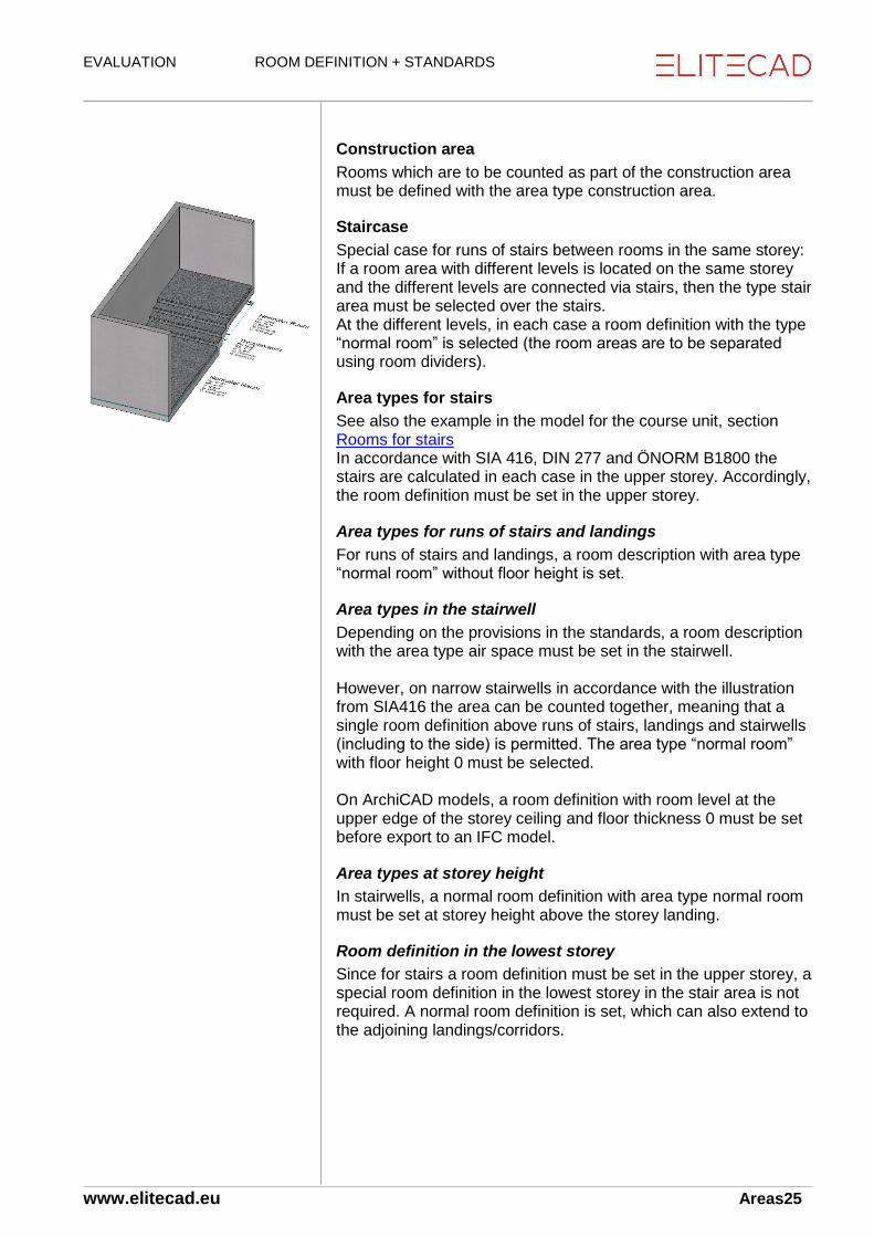
Staircase
Special case for runs of stairs between rooms in the same storey: If a room area with different levels is located on the same storey and the different levels are connected via stairs, then the type stair area must be selected over the stairs. At the different levels, in each case a room definition with the type “normal room” is selected (the room areas are to be separated using room dividers).
Area types for stairs
See also the example in the model for the course unit, section Rooms for stairs In accordance with SIA 416, DIN 277 and ÖNORM B1800 the stairs are calculated in each case in the upper storey. Accordingly, the room definition must be set in the upper storey.
Area types for runs of stairs and landings
For runs of stairs and landings, a room description with area type “normal room” without floor height is set.
Area types in the stairwell
Depending on the provisions in the standards, a room description with the area type air space must be set in the stairwell. However, on narrow stairwells in accordance with the illustration from SIA416 the area can be counted together, meaning that a single room definition above runs of stairs, landings and stairwells (including to the side) is permitted. The area type “normal room” with floor height 0 must be selected. On ArchiCAD models, a room definition with room level at the upper edge of the storey ceiling and floor thickness 0 must be set before export to an IFC model.
Area types at storey height
In stairwells, a normal room definition with area type normal room must be set at storey height above the storey landing.
Room definition in the lowest storey
Since for stairs a room definition must be set in the upper storey, a special room definition in the lowest storey in the stair area is not required. A normal room definition is set, which can also extend to the adjoining landings/corridors.

EVALUATION ROOM DEFINITION + STANDARDS
www.elitecad.eu Areas26
Area types for shafts
For shafts, the following area types are available:
Air space
Construction area
Lift shafts, lifts
SIA416 + DIN277
In each storey, a room definition must be set with the area type “normal room”, but with floor height 0
ÖNORM B1800
The area is only counted at the lowest support. A room definition is set there with the area type “normal room”, but with floor height 0. On the other storeys, a room definition with area type air space must be set.
Other shafts
In most cases, shafts must be counted as part of the area in all standards. This is achieved using a room definition with area type “normal room”. However, if the shaft is to be included in the construction area, then no room definition must be set, or alternatively one with area type “construction area”.
Living Space Ordinance (WoFlV) Germany
In order that the area is not counted as living space, the figure 0 (%) is entered for the percentage of living space.

EVALUATION ROOM DEFINITION + STANDARDS
www.elitecad.eu Areas27
Additional entry fields for room definition
Floor covering depth and layer construction
Floor covering depth
The floor covering depth reduces the room height and thus influences the volume and the living space. Select thickness 0 above runs of stairs. The volume of the stairs reduces the space.
Floor construction (floor covering)
The floor covering thickness must correspond to the total thickness of the floor covering.
Additional floor construction
For an existing room definition, the topmost covering layer can be changed using the “Definition of an additional floor construction” button, or an additional covering layer on top can be created.
Plaster depth The plaster depth is used to determine the net room space. These are issued for living spaces and for the area lists.
Plaster depth dependent on wall material
If the button to the right next to the input field is locked, then the plaster thickness or covering thickness proceeds in accordance with the set values, Index of wall covering thickness, so long as the wall material and the covering thickness are recorded in the list. On the other walls, the covering thickness of the room definition (illustration) is then calculated. This means that different wall covering thicknesses can be taken into account for the room area calculations (e.g. living space).
Additional/Deduction area
If an additional wall covering is recorded using the button below the input field for plaster thickness, then the thickness entered is taken into account for the living space calculation.
Deduction for plaster Only for living space, Germany. In accordance with invalid standard “2nd Calculation Ordinance”.
Room label: Marking deduction for plaster.

EVALUATION ROOM DEFINITION + STANDARDS
www.elitecad.eu Areas28
Max. room height For areas (e.g. DIN 277) and living spaces.
If no maximum room height is entered (0), then the room height is measured without limit.
Wall coverings are calculated to the upper edge of the shell floor.
The volume between the maximum room height and the storey height is evaluated as construction volume. Accordingly, the maximum room height does not reduce the volume of the building.
For external areas, the room height must be limited with height definitions. Example: Room coverings with maximum room height
Living space percentage Only for living spaces. Evaluation factor of room areas, according to room type. Note regarding the standards:
DIN 277: This standard does not recognize assessed living spaces, but all areas are calculated.
The living spaces ordinance (WoFlV) in Germany requires every area to be evaluated.
Setting options
Living space percentage in accordance with WoFlV 0-100%, depending on room type.
For the options in quantities manager, the limit heights are set with the corresponding factors. WoFlV: Parts of the room under 1 m height are not counted as living space. Parts of the room between 1 and 2 m are calculated using the factor 0.5. Parts of the room above 2 m in height are calculated in full.
The area type “air space” is evaluated as 0% living space percentage.
In the options, the minimum window niche depth can be set: o 0 m: niches are not evaluated. o 0.13 m: Pre-set for Germany in accordance with WoFlV o 0.001 m: Example for minimum value, so that the niches are evaluated.

EVALUATION ROOM DEFINITION + STANDARDS
www.elitecad.eu Areas29
3.3 Room group
Toolbar *Create new AR objects
Using the room group, calculations from different room definitions can be summarized together. Type: A setting can be saved using the Dataset menu. Designation: Title of the room group stamp Filter criteria:
Name: Room name
Unit
Section
Number (room number)
Use type NGF
Area type (Area a b, c. Germany + Austria
Across storeys (restricted to structure.
Labelling parameters
Type: If the imaging depth is changed, the corresponding parameters are also changed.
Label (title of the room group stamp)
The rest by analogy with room definition

EVALUATION ROOM DEFINITION + STANDARDS
www.elitecad.eu Areas30
Examples of room groups
Totals
Any room group stamp - title, e.g. “Total Structure 1” If nothing is entered for the filter criteria, then all are selected. If across storeys is enabled, all storeys in the structure are calculated. The room group stamp can be set in any storey, including the level “without storey”. Labelling parameters: Room group stamp-title Area and perimeter Living spaces (evaluated) and percentage share by reference to all areas Volume NRI or NGV
Unit
Room stamp title (any designation), e.g. “4 ½ - room flat, 1st floor left” Filter: Flat name in accordance with room definition Cross-storey enabled
Floor space storey
Title, e.g. “Main floor space HNF, 1st floor” Filter: Use type, e.g. HNF Cross-storey not enabled.

EVALUATION ROOM DEFINITION + STANDARDS
www.elitecad.eu Areas31
Room total
If several room definitions need to be set in one room (examples: rooms with different levels, rooms with inclined floor screed with different inclines or directions of slope), then these can be summarized into one room group stamp, with the exception of the room facings. Room group title (as preferred), e.g. “covered parking area” Filter: Room name in accordance with room definition
Notes
In the event of adjoining room definitions (with the same names), no perimeter is calculated for the room division. In the evaluation lists, the room group stamps are not taken into consideration. If a room is subdivided with two room definitions, two rooms are also calculated.

EVALUATION ROOM DEFINITION + STANDARDS
www.elitecad.eu Areas32
3.4 External rooms
Covered external rooms Model: Structure EFH, Terrace
In the room definition, always select type external room In BIM2COST, for external rooms there is no allocation to cost components wall facings and ceiling facings. For floor coverings, there is an allocation to flat roof facings
Use type SIA 416 ANF, AVF or AFF If the use type is chosen incorrectly, the external storey area cannot be calculated correctly.
Use type ÖNORM B 1800 HNF and Area Type b (covered) If the area type is chosen incorrectly, the net area of Area b cannot be calculated correctly.
Area DIN 277 b (covered)
Area type DIN 277 in accordance with standard, e.g. NF1
Living area percentage in accordance with WoFlV, usually 50%
Non-covered external rooms SIA 416: as for covered external rooms. DIN 277 and ÖNORM B1800: Area c instead of b.
EVALUATION ROOM DEFINITION + STANDARDS
www.elitecad.eu Areas33
Room volume for external rooms
Height definition
Limited effect of height definitions and room heights
New feature in EliteCAD AR13:
The height definition does not limit the room height for living space calculations.
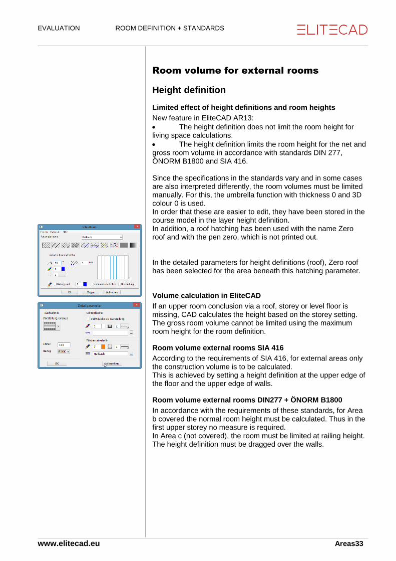
The height definition limits the room height for the net and gross room volume in accordance with standards DIN 277, ÖNORM B1800 and SIA 416. Since the specifications in the standards vary and in some cases are also interpreted differently, the room volumes must be limited manually. For this, the umbrella function with thickness 0 and 3D colour 0 is used. In order that these are easier to edit, they have been stored in the course model in the layer height definition. In addition, a roof hatching has been used with the name Zero roof and with the pen zero, which is not printed out. In the detailed parameters for height definitions (roof), Zero roof has been selected for the area beneath this hatching parameter.
Volume calculation in EliteCAD
If an upper room conclusion via a roof, storey or level floor is missing, CAD calculates the height based on the storey setting. The gross room volume cannot be limited using the maximum room height for the room definition.
Room volume external rooms SIA 416
According to the requirements of SIA 416, for external areas only the construction volume is to be calculated. This is achieved by setting a height definition at the upper edge of the floor and the upper edge of walls.
Room volume external rooms DIN277 + ÖNORM B1800
In accordance with the requirements of these standards, for Area b covered the normal room height must be calculated. Thus in the first upper storey no measure is required. In Area c (not covered), the room must be limited at railing height. The height definition must be dragged over the walls.

EVALUATION ROOM DEFINITION + STANDARDS
www.elitecad.eu Areas34
3D check on height definitions
Set up layer height definition in all storeys. Note: In the Switzerland evaluation model the parapet coverings are drawn as a roof in the layer, and as a result the specifications of SIA 416 are satisfied for the external construction volume. In order for the location of these height definitions in the space to be made visible, the 3D colour on an individual height definition is changed temporarily. Transfer 3D representation on screen or for the Switzerland evaluation model individually.
Model Switzerland When zooming, interferences form between the 3D colour of the height definition and the room floor or the upstands (wall) when concluding with a flat roof. Note If despite the specification in the standard a net room volume is preferred, the height definitions must be set to the desired height. In the lists for SIA 416, the unofficial volume is then accordingly taken into account under external net building volume ANGV and external building volume AGV.

EVALUATION ROOM DEFINITION + STANDARDS
www.elitecad.eu Areas35
Model Germany + Austria In addition, also set up an empty layer The height definitions limit the volume above the non-covered Areas c.
EVALUATION ROOM DEFINITION + STANDARDS
www.elitecad.eu Areas36
3.5 Storey areas in the standards
SIA416
GF
The storey area (Geschossfläche, GF) comprises only the internal rooms (NGF, net storey area) and the walls and constructions limiting the internal rooms (KGF, construction area).
AGF
The external storey area (Aussengeschossfläche, AGF) comprises the external rooms (ANGF - external net storey area) and the walls and constructions limiting the external rooms (Aussen-Konstruktionsfläche, AKGF), where the latter do not form part of the storey area GF. However, without manual perimeter contour AGF these are not included in the count. The storey area is not yet divided in the current versions BIM2COST R3. In EliteCAD AR13 and BIM2COST R4 and above, rooms with external labels ANF, AVF, AFF are automatically counted in the external storey area AGF and the external net storey area ANGF.
Manual perimeter contour
With the manual perimeter contour, the construction areas can also be assigned to the external storey area ANGF. See Perimeter contour (Chapter 3.7)
DIN 277 and ÖNORM B1800
BGF
The gross floor area (Bruttogrundfläche, BGF) comprises all internal and external areas (NGF) and all internal and external construction areas (KGF). These areas are divided into the areas: a Internal rooms b External rooms covered c External rooms not covered: BGFa, BGFb, BGFc, KGFa, KGFb, KGFc, NGFa, NGFb, NGFc
Manual perimeter contour
Using the manual perimeter contour, the construction areas can also be assigned to External Areas b and c. See Perimeter contour (Chapter 3.7)
Reports and area labels
The reports are created in such a manner that standardized area labels must be selected for the area types and use types.

EVALUATION ROOM DEFINITION + STANDARDS
www.elitecad.eu Areas37
3.6 Room + storey in quantities
manager
Living space
Living spaces are described in the Chapter 3.8 Living space and verification
Room finishes
Room finishes are described in Chapter 4. Room finishes
Construction parts toolbar
Extras menu > Evaluation > Quantities manager
Toolbar > Evaluation > Quantities manager
Storey in quantities manager
Display mode hierarchy
New mode in EliteCAD AR13 When you select the storey or structure the calculated values are listed in the tab Values and Attributes. When selecting the structure, the total for all storeys is listed for the values.
Display mode structure
When you select the storey or structure the calculated values are listed in the tab Values and Attributes.
Display mode object types
With the object types mode, the structure is not displayed. At the top, the storeys of the first structure are listed.

EVALUATION ROOM DEFINITION + STANDARDS
www.elitecad.eu Areas38
The room in quantities manager
Mode hierarchy
Select structure The storeys are subordinate to the structure The rooms are subordinate to the storey Select room
Room finishes
The room finishes are subordinate to the room The layers are subordinate to the higher-level grouping finish sublayer and covering finish Selection in quantities manager displays these in the CAD
Living space
The living space is subordinate to the room
Display
Example floor covering finish Example living space

EVALUATION ROOM DEFINITION + STANDARDS
www.elitecad.eu Areas39
Display mode structure
With the structure display, the individual layers and the living spaces are hidden using the active filter for object type display. It is optimized for BIM2COST display type (cost estimate) Filter disabled Display of all object types
Display mode object types
The display type with filter function is similar to the structure display mode, but without a breakdown into structures and storeys.
EVALUATION ROOM DEFINITION + STANDARDS
www.elitecad.eu Areas40
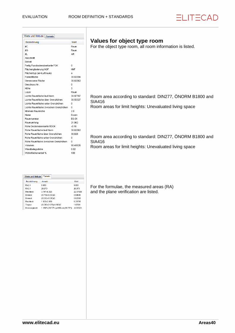
Values for object type room For the object type room, all room information is listed. Room area according to standard: DIN277, ÖNORM B1800 and SIA416 Room areas for limit heights: Unevaluated living space Room area according to standard: DIN277, ÖNORM B1800 and SIA416 Room areas for limit heights: Unevaluated living space For the formulae, the measured areas (RA) and the plane verification are listed.

EVALUATION ROOM DEFINITION + STANDARDS
www.elitecad.eu Areas41
3.7 Perimeter contour
Menu AR objects > Perimeter contour
When evaluating, the CAD creates an (automatic) perimeter contour in each storey. The perimeter contour comprises the outer room-dividing elements. The perimeter contour forms the basis for:
Gross floor area BGF as the total of a, b and c in accordance with DIN 277 and ÖNORM B1800
Total of storey area GF and external storey area AGF in accordance with SIA 416
The areas can be divided up using the perimeter contour function.
Calculation of areas without adjustments
Area a (Germany and Austria)
Net floor area NGFa: Total of all rooms in Area a Gross floor area BGFa: All areas Construction surface area: Difference BGFa-NGFa
Area b (Germany and Austria)
Net floor area NGFb: Total of all rooms in Area b Gross floor area BGFb: Total of all rooms in Area b Construction surface area: 0 (no areas)
Area c (Germany and Austria)
By analogy with Area b
Storey area GF (Switzerland)
All areas
Net storey area NGF (Switzerland)
All rooms labelled internal rooms in accordance with the SIA standard
Construction surface area KGF (Switzerland)
Difference between all areas - NGF
External storey area AGF (Switzerland)
All rooms labelled external rooms in accordance with the SIA standard
External net storey area ANGF (Switzerland)
All rooms labelled external rooms in accordance with the SIA standard
External construction surface area AKF (Switzerland)
0 (no areas)

EVALUATION ROOM DEFINITION + STANDARDS
www.elitecad.eu Areas42
Edit perimeter contour
Evaluation after changing perimeter contours After altering perimeter contours, a re-evaluation is required in accordance with the following section.
Requirement
1. Room and perimeter contours must be switched on:
Menu Settings > Options > Display
Under Display > Architecture, enable the room perimeter option. 2. The model must be evaluated (otherwise no perimeter
contours are present)
Setting up a perimeter contour
The perimeter contours are located in the perimeter contour layer. These should be set up together with the walls (wall layer) and other room-dividing construction parts.
Adjusting the automatic perimeter contour
The properties toolbar is displayed simply by selecting the perimeter contour. Simply by selecting the perimeter contour, the input aids for editing the perimeter contour like a polygon are displayed.
Area a (DE + AT) or GF (CH)
The Automatic Perimeter Contour is taken back to the internal area using the normal editing functions for polygons:
Germany and Austria Area a for BGFa
Switzerland Storey area GF In the 1st upper storey, set up layer perimeter contour and wall. Hide the parapet on a terrace and switch to the wireframe model. Select the perimeter contour in the CAD (in the parapet area). In the properties toolbar, the automatic perimeter contour is displayed with the coloured symbol. Switzerland: Perimeter contour GF (illustration), Austria and Germany: Perimeter contour a (illustration on previous page). Now the perimeter contour is taken back to the right to the external facade. This converts it to a manual perimeter contour.
Creating manual perimeter contours
After the automatic perimeter contour has been changed, it is converted into a manual perimeter contour.

EVALUATION ROOM DEFINITION + STANDARDS
www.elitecad.eu Areas43
Drawing perimeter contours for external areas
Menu Extras > AR objects > Perimeter contour
1st upper storey Germany + Austria: Select Perimeter Contour b. Switzerland: Select Perimeter Contour AGF. Use the drawing function rectangle to draw the external area.
Labelling the manual perimeter contour If a contour has previously been drawn using the 2D functions, this can be labelled as a perimeter contour by switching to the properties toolbar.
Calculating the perimeter contour automatically (without previous evaluation) The perimeter contour parameter mask must be opened.
Using the “Calculate perimeter contour automatically” button, the CAD creates a perimeter contour around all room-dividing construction parts, including those not built up.

EVALUATION ROOM DEFINITION + STANDARDS
www.elitecad.eu Areas44
3.8 Plane(s) verification rooms
Graphical planes verification
Settings
Menu Settings > Options
Work parameters > Plane(s) verification Text parameter(s) Pens for surface contour and for deductions
Create
Menu Extras > Evaluation > Plane(s) verification
Toolbar Evaluation > Plane(s) verification
Determine selection The contours are created in the plane(s) verification layer. The display of part areas and their docu-texts are carried out in accordance with the settings. The room-dividing construction parts are created using Pen 5.
For the plane(s) verification list, graphical plane(s) verification in the CAD is not a mandatory requirement.
Using “Model Information”, the calculation can be checked in the drawing.
In the example here, the colouring demonstrates how the areas are calculated.
Plane(s) verification list
1.2.91 Plane(s) verification rough dimensions
EVALUATION ROOM DEFINITION + STANDARDS
www.elitecad.eu Areas45
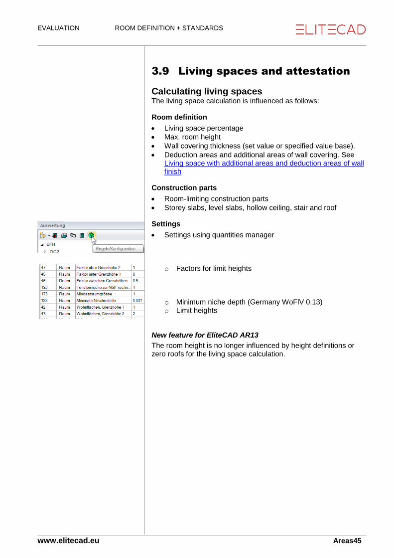
3.9 Living spaces and attestation
Calculating living spaces The living space calculation is influenced as follows:
Room definition
Living space percentage
Max. room height
Wall covering thickness (set value or specified value base).
Deduction areas and additional areas of wall covering. See Living space with additional areas and deduction areas of wall finish
Construction parts
Room-limiting construction parts
Storey slabs, level slabs, hollow ceiling, stair and roof
Settings
Settings using quantities manager
o Factors for limit heights
o Minimum niche depth (Germany WoFlV 0.13) o Limit heights
New feature for EliteCAD AR13
The room height is no longer influenced by height definitions or zero roofs for the living space calculation.

EVALUATION ROOM DEFINITION + STANDARDS
www.elitecad.eu Areas46
Living space in quantities manager Living spaces are displayed using different colours in the living space object type. In the index of values and attributes, the calculation results are listed. In the formulae index, the part areas are listed with the calculation key.
Graphical living space verification
Settings
Menu Settings > Options
Work parameters > Plane(s) verification Section living space verification Text parameter(s) Pens for surface contour and for deductions The contours are created in the plane(s) verification layer. The display of part areas and their docu-texts are carried out in accordance with the settings. The part areas are broken down by limit heights and marked with cross-hatching using the same colours as in the display via quantities manager. The room-dividing construction parts are created using Pen 5.
Living space verification list
1.2.91 Living space verification of areas

EVALUATION ROOM DEFINITION + STANDARDS
www.elitecad.eu Areas47
Living space calculation with different wall covering thicknesses.
Setting dependent on wall material (base)
Example in the course model Storey 1st Upper Level, dividing wall between Room 2 and Room 1 is a plaster partition wall. If in the room parameters for wall covering thickness the button to the right next to the input field is locked, then the plaster thickness or covering thickness proceeds in accordance with the set values, Index of wall covering thickness, so long as the wall material and the covering thickness are recorded in the list. On the other walls, the covering thickness of the room definition (illustration) is then calculated. For the example, in the Index of wall covering thickness, thickness 0 is entered for plaster. For that reason, the control layer living space attaches living space with deduction for plaster 100% to the dividing wall. (Select solid display). On the other walls, a different wall covering thickness is calculated.

EVALUATION ROOM DEFINITION + STANDARDS
www.elitecad.eu 48
4. Room finishes The settings for the room definition are described in Chapter 3.
4.1 Room finishes, general
Materials The names of materials for floor finishes and the assignment to the layer groups covering finish and covering finish sublayer is carried out using the overarching term for synonyms and the layer types floor on facing or subconstruction. See diagram: Management using materials For wall and slab finishes, in BIM2COST only the synonyms are effective.
Floor finishes
Contours of floor finishes
The floor finishes are calculated using the room contour. The main contour of the floor finish cannot be changed. The individual layers of the floor finish can be extended in EliteCAD AR13. For this, the individual layer can also be extended via the main contour (by contrast with normal multi-layer construction parts.
Room definitions without floor finish
For the area type air space, no floor finish is calculated. If a normal room definition is located above a slab, then no floor covering is calculated. Floor finishes are only calculated via level and storey floors.
Floor finish on stairs
A floor finish is calculated on stairs.
Multi-layered floor finishes
Floor covering finish
The layer group floor covering finish is set via the facing layer type.
Floor finish sublayer
The layer group floor finish sublayer is set via the sub-construction layer type.
Additional and deduction planes
The topmost covering layer can be deducted to a part area or replaced. Via the topmost covering layer, an additional layer can be created.

EVALUATION ROOM DEFINITION + STANDARDS
www.elitecad.eu 49
Lists
The layers are listed in groups if the individual layers have the same dimensions. The floor finish sublayers are listed with the Swiss specialist term “Unterlagsboden” (subfloor). A subfloor contains possible insulation layers, together with the screed.
Flat roof coverings in BIM2COST
The flat roof coverings for cost estimating in BIM2COST are determined using the floor covering, area type external room
Wall finishes
Determining wall finishes
In EliteCAD, the wall finishes are not drawn, but calculated from the room-limiting construction parts. Wall finishes are calculated for:
Walls, room-dividing and non room-dividing
Slab faces
Facings on girders On wall openings, the deduction audit establishes whether the opening can be deducted accordingly from the trade Plaster.
Upper and lower limit of wall finishes
Wall finishes are limited by:
Storey and level floor
CAD floor of type roof
CAD floor of type stair landing
CAD floor of type hollow ceiling
Stairs adjoining wall
Roofs
Max. room height in room definition
Height definitions
Base and object types
Wall finishes are evaluated separately by base material and accordingly listed in different object types. Model: Structure EFH, Basement Section 3 Wall covering finish RA11.2 On base separating system In the wall finishes list, the finishes for each base are listed separately.

EVALUATION ROOM DEFINITION + STANDARDS
www.elitecad.eu 50
Layers for wall finishes
In EliteCAD only one layer can be entered. In BIM2COST multiple layers can be entered.
Wall covering finish
In EliteCAD, the layer becomes the wall covering finish In BIM2COST, the imported layer becomes the wall covering finish.
Wall finish sublayer
In BIM2COST wall finish sublayers can additionally be entered.
Additional and deduction planes
The wall finish can be deducted to a part area or replaced. Via the wall finish, an additional layer can be created.
Allocation rules in BIM2COST general
The allocation rules to cost components in BIM2COST take account of the wall finish bases. Examples: On bases such as glass, lath partition etc. there is no allocation to cost components. On bases such as plaster and plasterboard, only the covering finish is allocated to cost components. On bases like concrete, there is an additional allocation to the cost component base plaster (logical total structure).
Allocation rules in BIM2COST materials
In BIM2COST there are allocation rules to cost components in place both for the ceiling finish of the room definition and also for drawn building components. Example: Room definition with wall finish timber formwork and wall facing timber formwork. Optimization can be undertaken as follows: Option 1: Room definition without material description or a material name which is not allocated to the overarching term timber facing. Option 2: Analogous procedure with material name for wall facing. Option 3: Modify allocation rules.

EVALUATION ROOM DEFINITION + STANDARDS
www.elitecad.eu 51
Calculation, deduction audit and quantities manager
In the top illustration (Switzerland), the openings are deducted, in the lower illustration (Germany) they are not. The deduction limits are defined differently for the countries using Options (Chapter 7.3). Material as per room definition (only object type wall finish + wall finish layer) Material group describes the overarching term as per the synonyms setting (only object type wall finish + wall finish layer). Material information contains all overarching terms for materials which the object type contains (object types wall covering finish and wall finish sublayer can comprise multiple layers in BIM2COST). Detailed calculation in the index of formulae

EVALUATION ROOM DEFINITION + STANDARDS
www.elitecad.eu 52
Slab finishes
Determining slab finishes
In EliteCAD, the slab finishes are not drawn, but calculated from the room-limiting construction parts. Slab finishes are calculated on the underside of
Storey and level floors
CAD floors of type roof
CAD floors of type stair landing
CAD floor of type hollow ceiling
Stairs
Roofs If a maximum room height is defined in the room definition, the slab finish is calculated at this height. If no component (in line with the above listing) is present either in the current storey or in the storey above, then no slab finish is calculated in EliteCAD.
Layers for slab finishes
In EliteCAD only one layer can be entered. In BIM2COST multiple layers can be entered.
Slab covering finish
In EliteCAD, the layer becomes the slab covering finish In BIM2COST, the imported layer becomes the slab covering finish.
Slab finish sublayer
In BIM2COST slab finish sublayers can additionally be entered.
Additional and deduction planes
The slab finish can be deducted to a part area or replaced. Via the slab finish, an additional layer can be created.
Cost allocation rules BIM2COST for materials
By analogy with wall finish

EVALUATION ROOM DEFINITION + STANDARDS
www.elitecad.eu 53
4.2 Multi-layered floor finishes
Create floor finish Model: Structure: EFH, GF Residential
Room definition Section floor. The material description takes priority for the topmost layer. Here granite Right button, parameter(s) for floor construction The topmost layer is defined with the material slab. This material is overridden by the material in the room definition (meaning that there is no need to record each material as a parameter for the imaging depth. Via the lock, the material is linked with the settings for the layer types (quantities manager). Here the slab material is defined as a facing layer type. The other layer types are defined by the link as a sub-construction layer type.
Modifying layer contours Model: Structure: EFH, GF Shower The pedestal is marked as a non room-dividing wall. Note: In the evaluation model, the floor finish was already modified. The procedure for the unmodified floor finish is described below. Construct room Image before changing layer contours For the pedestal, the floor finish is continuous with all layers. Under the shower, the floor finish is continuous.

EVALUATION ROOM DEFINITION + STANDARDS
www.elitecad.eu 54
Edit floor finish
Each individual layer must be edited. For the procedure, see the Manual section on rooms. For the pedestal, all layers were removed. Below the shower, only the insulation layer has been left untouched.
Floor finishes and BIM2COST
Normal floor finishes
Allocation to cost components floor finishes room.
G 2.1.1 Screeds in composite (Rooms in basement) G 2.2.1 Floating screeds (GF) G 2.3.x Floor covering finish as per material
Flat roof coverings
Allocation to cost components for flat roof covering
Requirement: Area type external room Model: Structure EFH, Upper Storey 2 Terrace F 1.2.1 Upstands and downstands F 1.2.5 Seals with insulation F 1.5.x External floor coverings by material Here F 1.5.2 Protective layer flat roof capable of being walked on

EVALUATION ROOM DEFINITION + STANDARDS
www.elitecad.eu 55
4.3 Additional and deduction planes
Additional and deduction planes for floor
finishes
Additional finish for floor finishes
Model: Structure: EFH, GF Residential Button definition of an additional floor construction Thickness Material Outline pen Texture Option replace for wall finish not enabled Draw outline (masks must be open) In the model, this additional floor finish is already inserted.

EVALUATION ROOM DEFINITION + STANDARDS
www.elitecad.eu 56
Replacement finish for floor finishes
Model: Structure: EFH, GF Area in front of stairs Option replace for room finish enabled
Remove floor covering finish
With normal change of layer contours. See Modifying layer contours Alternatively, the floor covering finish can also be removed via the room definition. Model EFG, GF Kitchen. Construct room definition and kitchen furniture Without materials Option replace for room finish enabled By contrast with the method for modifying layer contours, the surface is replaced with a 3D surface with the property deduction area. In quantities manager, select floor covering finish The floor covering finish is cut out With the deduction area method, an object type floor covering finish CO is created. The subfloor (object type floor finish sublayer) is not cut out.

EVALUATION ROOM DEFINITION + STANDARDS
www.elitecad.eu 57
Additional and deduction planes for wall
finishes
Additional finish for wall finishes
Model: Structure EFH, Shower Button definition of an additional wall construction Thickness Material Outline pen Texture Option replace for room finish disabled In the model, this additional area is already inserted.

EVALUATION ROOM DEFINITION + STANDARDS
www.elitecad.eu 58
Deduction planes for wall finishes
Model: Structure EFH, Basement Cubicle No thickness No materials Option replace for room finish enabled The area is drawn over the cubicle dividing wall Depending on the setting of the deduction audit plaster, the doors are cut out. In the model, this deduction area is already inserted. For the first wall covering finish (on this wall), nothing is displayed. For this, a wall covering finish CO is created for the deduction area. In the wall covering list, now only the deduction area remains listed on the base cubicle dividing wall, while the material “painted” is no longer showing.
Deduction planes for BIM2COST
On this wall, in BIM2COST no allocation to a cost component is made even without any deduction plane (base cubicle dividing wall). The deduction planes are taken into account in BIM2COST.
Replacement areas for wall finishes
Analogous procedure, but with option replace for room finish enabled.

EVALUATION ROOM DEFINITION + STANDARDS
www.elitecad.eu 59
Additional and deduction planes for
ceiling finishes The procedure is the same as for wall finishes
Living space with additional areas and
deduction areas of wall finish If an additional area is inserted for a wall finish, the living space is reduced by the thickness of the additional finish Model: Structure: EFH, GF Shower Additional wall finish (mirror) reduces living space If a deduction area is inserted for a wall finish, the living space is increased at this spot (not illustrated)

EVALUATION ROOM DEFINITION + STANDARDS
www.elitecad.eu 60
4.4 Room finishes in special rooms
and situations
Room finishes for special construction
parts
Room finishes for girders Model: Structure Timber construction, Basement Garage If the evaluate finishes option is set, then ceiling finishes are calculated to the side of the girder
Wall finish for parapet with brick cladding Model: Structure EFH, Upper Storey 1 Bathroom The wall finish is also calculated on non room-dividing walls (brick cladding for WC)

EVALUATION ROOM DEFINITION + STANDARDS
www.elitecad.eu 61
Room finishes with max. room height Model: Structure Timber construction, Upper Storey 2 Corridor Image before modification. The ceiling covering finish is located on the soffit The wall covering finish is calculated up to the soffit Edit room definition and reduce max. room height to 400 cm For this change to take effect, a re-evaluation is required The first ceiling covering finish is located horizontally at height 400 cm The second ceiling covering finish is located on the soffit up to room height 400 cm The wall covering finish is calculated up to room height 400 cm.

EVALUATION ROOM DEFINITION + STANDARDS
www.elitecad.eu 62
The room box display indicates that the net room volume is also reduced.
Room finishes for hollow ceilings New feature for EliteCAD AR13 Model: Structure EFH, GF Kitchen Beneath the storey ceiling in the kitchen room is a CAD floor of type hollow ceiling (suspended ceiling). The upper layer was set transparently using the 3D functions. To illustrate: Construction of room definition and wall The ceiling covering finish was calculated on the underside of the hollow ceiling. The wall covering finish is limited in height by the hollow ceiling. Room box diagram: The net room volume is reduced by the hollow ceiling
EVALUATION ROOM DEFINITION + STANDARDS
www.elitecad.eu 63
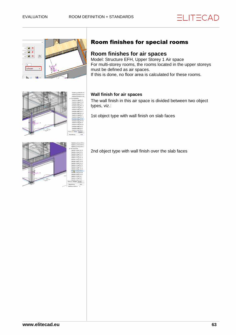
Room finishes for special rooms
Room finishes for air spaces Model: Structure EFH, Upper Storey 1 Air space For multi-storey rooms, the rooms located in the upper storeys must be defined as air spaces. If this is done, no floor area is calculated for these rooms.
Wall finish for air spaces
The wall finish in this air space is divided between two object types, viz.: 1st object type with wall finish on slab faces 2nd object type with wall finish over the slab faces

EVALUATION ROOM DEFINITION + STANDARDS
www.elitecad.eu 64
Room finishes for stairs
Rooms with stairs in the lowest storey
Model: Structure EFH In the lowest storey, a room definition of the type “normal room” can be selected. This room may also lead into adjoining corridors. Select wall finish in quantities manager. Stairs adjoining a wall limit the wall finish beneath the stair. The ceiling finish in this room is on the underside of stairs and ceilings. In the CAD, construct the room definition and switch to room box display. The room is height-limited for the stairs both for the calculation of volume and also for the living space calculation.
Rooms in the upper storeys
Illustrations with hidden layers roof and roof truss. The room definition must be divided up. For the 1st room definition over the storey floor, the normal room type is selected (do not select stairwell type! See exceptional instance Stairwell Chapter 3.1).

EVALUATION ROOM DEFINITION + STANDARDS
www.elitecad.eu 65
The 2nd room definition above the staircase is separated by a room division. Note: Under standards DIN 277, ÖNORM B1800 and SIA 416, stairs are always calculated in the upper storey. For that reason, a room definition must be set here with the entries shown below. Select room definition in the CAD.
normal room
Floor thickness 0 This means no 3D floor is created. The floor area of the room is, however, calculated normally. Select floor finish in quantities manager. The floor finish is always calculated into the next lower storey. If the stair does not adjoin a wall (as in this model in this storey), the wall finish is calculated from the lower edge of the storey ceiling. In the ground floor, the finish is calculated to the stairs into the basement, since the stairs are connected to the wall (1st part wall finish). Since the stairs to the upper storey do not adjoin the wall, the wall finish is calculated to storey height (2nd part wall finish).

EVALUATION ROOM DEFINITION + STANDARDS
www.elitecad.eu 66
Jamb wall spaces, shafts, construction area In the CAD, select jamb wall in the topmost storey. If a room is not to be counted as part of the net storey area (SIA 416), or net area (DIN 277 + ÖNORM B1800) and if no room finishes are to be calculated either, then no room definition must be set, or one with type construction area. Rooms with area type construction area are not listed in quantities manager. No room finishes are calculated.

EVALUATION CONSTRUCTION PARTS
www.elitecad.eu 67
5. Construction parts
5.1 General
Room-forming functions
Overview Walls (can be selected to separate rooms)
Girder from wall function (can be selected to separate rooms)
Column
Chimney
Glass elements (can be selected to separate rooms)
Room separator
Use of room-separating functions EliteCAD calculates polygons from the arrangement of the
room-separating functions. If this is locked, a room definition can be inserted.
EliteCAD calculates the perimeter contour from the arrangement of the room-separating functions, which is used to calculate the storey area. This perimeter contour must be closed.
Errors in the application
Room-separating functions must not overlay one another. Example: If two walls are drawn over one another, then only one wall can be set as room-separating.
Room separators may not be run along room-separating walls.
Room separators must not cross one another.
Height-separating functions
Overview
Height separating on the underside and upper side
Rooms can be separated on the underside and upper side in height using the following functions:
CAD floors with height reference level floor and storey floor
CAD floors of type stair landing
Height-separating on the underside
CAD floors of type hollow ceiling with height reference free slab
Roof and height definition

EVALUATION CONSTRUCTION PARTS
www.elitecad.eu 68
5.2 CAD floors
Overview Various construction parts are created using the floor function. Internal foundation External foundation (external foundation for balconies and pergolas) Single foundation Strip foundation Foundation slab Roof (for flat roofs above and below terrain) Stair landing Hollow ceiling (suspended ceiling)
Height reference
The height reference simultaneously defines whether the floor is height-limiting (room) or not:
Free slab, not height-limiting.
Storey floor, height-limiting
Level floor, height-limiting
Special floor setting: Hollow ceiling
The hollow ceiling always defines the room on the underside of the hollow ceiling. The hollow ceiling must be drawn as a free slab.

EVALUATION CONSTRUCTION PARTS
www.elitecad.eu 69
Foundations
Foundation slabs In the CAD, select the floor slab as per the illustration. Open the parameter mask
Foundation slab
Waterproofing concrete > load-bearing
Insulation > Facing
Lean concrete > Subconstruction
Gravel layer > non load-bearing
Concatenation with material: Load-bearing for waterproofing concrete material
Layer type Object type
Load-bearing Foundation construction
Non load-bearing Foundation subfloor
Subconstruction Socket concrete
Facing Foundation insulation
Cost allocation rules in BIM2COST 13
C 1.2.1 Seals C 1.2.2 Insulation C 1.4.1 Gravel pack C 1.4.4 Socket concrete C 1.5 Slab bearing
List for foundations
2.2.01 Foundations Breakdown by foundation types and layer types

EVALUATION CONSTRUCTION PARTS
www.elitecad.eu 70
Strip foundations Strip foundation Rest as above
Cost allocation rules in BIM2COST 13
C 1.3.2 Strip foundations
Single foundations Single foundation Rest as above
Cost allocation rules in BIM2COST 13
C 1.3.1 Single foundations

EVALUATION CONSTRUCTION PARTS
www.elitecad.eu 71
Ceilings
Concrete ceiling with cladding underneath Model: Structure EFH, Floor GF
Internal foundation
Concrete > load-bearing
Insulation > non load-bearing
Plasterboard > Facing Layer type Object type
Load-bearing Floor construction
Non load-bearing Floor construction, non-bearing
Subconstruction Floor subconstruction
Facing Floor facing
Cost allocation rules in BIM2COST 13
C 4.1.1 In-situ concrete ceilings or C 4.2.1 Stairs, if in stairs layer G 4.3.2 Panels (ceiling panelling)
Lists for internal ceilings
2.2.02 Concrete slabs 2.2.11 Various ceiling constructions and facings 2.2.91 All ceiling layers (without breakdown)
Ceiling with timber floor joists Model: Structure Timber construction, Floor Upper Storey 1
Internal foundation
Dead floor > Subconstruction
Beam insulation > load-bearing
Batten > Subconstruction
Gypsum fibre boards > Facing
Cost allocation rules in BIM2COST 13
C 4.1.5 Timber floors G 2.2.3 False floors G 4.2.2 Underconstructions (ceiling panelling) G 4.3.2 Panels (ceiling panelling)

EVALUATION CONSTRUCTION PARTS
www.elitecad.eu 72
Ceilings timber panel construction Model: Structure Timber construction, Floor Upper Storey 2
Internal foundation
Box element > load-bearing
Batten > Subconstruction
Gypsum fibre boards > Facing
Cost allocation rules in BIM2COST 13
C 4.1.5 Timber floors G 4.2.2 Underconstructions (ceiling panelling) G 4.3.2 Panels (ceiling panelling)
Lists for timber ceilings
2.2.11 Various ceiling constructions and facings 2.2.91 All ceiling layers (without breakdown)
Balconies in concrete Model: Structure EFH, Balcony Upper Storey 2
External foundation
Concrete > load-bearing
Cost allocation rules in BIM2COST 13
C 4.3.1 In-situ concrete balconies F 1.4 Lightning protection
Lists for concrete balconies
2.2.02 Concrete slabs 2.2.11 Various slab constructions and facings) 2.2.91 All slab layers (without breakdown)

EVALUATION CONSTRUCTION PARTS
www.elitecad.eu 73
Balconies in timber Model: Structure Timber construction, Balcony, Upper Storey 1
External foundation
Strip flooring > Facing
Cost allocation rules in BIM2COST 13
C 4.3.4 Timber balconies F 1.4 Lightning protection F 1.5 External floor finishes and ceiling finishes flat roof (additional cost component) F 1.5.6 Floor finishes in timber and timber materials
Roofs (from CAD floors) (Roofs created using the floor function)
Distinguishing roof - external foundation
Under the cost component method applied in BIM2COST, slabs which end a room above against the external area are considered as a roof. CAD slabs defined as a roof are listed in the roof list. However, if CAD slabs are listed in the slabs list, then external foundation should be selected and amended in BIM2COST to roof.
Concrete roofs below terrain Model: Structure EFH, Floor GF above store
Waterproofing concrete > load-bearing
Cost allocation rules in BIM2COST 13
C 4.4.1 In-situ concrete roofs F 1.1.4 Seal without insulation (with option in soil) F 1.4 Lightning protection
Lists for concrete roofs
2.2.03 Concrete roofs 2.3.91 All roof layers (without structure)

EVALUATION CONSTRUCTION PARTS
www.elitecad.eu 74
Concrete roof (flat room) above terrain Model: Structure EFH, Floor Upper Storey 2 Flat Roof Terrace
Roof
Concrete > load-bearing The roof skin (flat roof) is created with the room definition.
Cost allocation rules in BIM2COST 13
C 4.4.1 In-situ concrete roofs F 1.4 Lightning protection
Lists for concrete roofs
2.2.03 Concrete roofs 2.3.91 All roof layers (without structure)
BIM2COST
Do not enable in-soil in BIM2COST.
Timber flat roof Model: Structure Timber construction, Floor Upper Storey 1 Flat Roof Terrace
Roof
Dead floor > Subconstruction
Beam insulation > load-bearing
Batten > Subconstruction
Gypsum fibre boards > Facing The roof skin (flat roof) is created with the room definition.
Cost allocation rules in BIM2COST 13
C 4.4.5 Timber roofs F 1.4 Lightning protection G 4.2.2 Underconstructions (ceiling panelling) G 4.3.2 Panels (ceiling panelling) Lists for timber flat roofs 2.3.01 Roof planes and edges 2.3.91 All roof layers (without structure)

EVALUATION CONSTRUCTION PARTS
www.elitecad.eu 75
Stair landing The type stair landing is used for landings create from CAD floors. The room volume calculation and the room finishes then behave in a similar manner as for normal stairs. See also Example of stair with landing (Chapter 1.8). Reading in the stair landing model
Stair landing
Free slab
Rules (layer) stairs(for BIM2COST mandatory)
Concrete > load-bearing The floor finish is not created with the room definition, since two room definitions are not permitted to lie over one another in the same storey.
Cost allocation rules in BIM2COST 13
C 4.2.1 In-situ concrete stairs
Floor finish on stair landing
The floor finish is created with the floor function, internal foundation. This floor finish is only assigned in BIM2COST to the cost component floor finish.
Free slab
Granite > Facing
Screed > Subconstruction
Cost allocation rules in BIM2COST 13
G 2.1.1 Screeds in composite (if no insulation is present) G 2.2.1 Floating screeds (if insulation is present) G 2.3.6 Floor finishes in natural stone (or other finishes)

EVALUATION CONSTRUCTION PARTS
www.elitecad.eu 76
Concrete roofs (from CAD roofs) (Roofs created using the roof function) Without model template
Concrete > load-bearing
Cost allocation rules in BIM2COST 13
C 4.4.1 In-situ concrete roofs F 1.4 Lightning protection
Lists
2.2.03 Concrete roofs 2.3.91 All roof layers (without structure)

EVALUATION CONSTRUCTION PARTS
www.elitecad.eu 77
Hollow ceiling The type hollow ceiling is used for slab facings with or without subconstructions and for suspended ceilings. Examples: Insulation on the underside of cellar slabs, Slab facings in plasterboard, metal panels, etc. The room volume in accordance with DIN 277, ÖNORM B1800 and SIA 416 is limited at the top by the lower edge of the hollow ceiling. For the living space calculation (WoFlV), the lower edge of the hollow ceiling limits the room height. Model: Structure EFH, Slab above dining area
Free slab
Insulation > non load-bearing *)
Ceiling hollow chamber > Subconstruction
Plasterboard > Facing *) Layer types load-bearing and non load-bearing are evaluated like the layer type subconstruction for the hollow ceiling, as object type ceiling facing subconstruction. Hollow ceiling Object type
Load-bearing Slab facing subconstruction
Non load-bearing Slab facing subconstruction
Subconstruction Slab facing subconstruction
Facing Slab facing
Cost allocation rules in BIM2COST 13
G 4.2.2 Subconstruction G 4.3.2 Tiles (or other slab facings, such as timber, etc.)
Lists for hollow ceilings
G 2.2.21 Special slab facings 2.2.91 All slab layers (without breakdown)
IFC
In order for slab facings to be imported from another CAD as a hollow ceiling, in the export CAD these construction parts must be exported as a finish or covering with the type ceiling.

EVALUATION CONSTRUCTION PARTS
www.elitecad.eu 78
External ceiling soffits The external ceiling soffits should not be created together with the storey ceilings.
Soffit external insulation
External foundation
Free slab
External insulation > Facing
Cost allocation rules in BIM2COST 13
E 2.5.3 External thermal insulation soffit
Soffit timber panelling
External foundation
Free slab
Insulation > non load-bearing
Batten > Subconstruction
Roof boarding > Facing
Cost allocation rules in BIM2COST 13
E 2.5.1 Timber and timber materials (soffit) E 2.5.4 Coating (soffit) E 2.5.5 Insulation for back-ventilated facings

EVALUATION CONSTRUCTION PARTS
www.elitecad.eu 79
Floor function floor surrounding areas The floor function can be used to evaluate surrounding areas. Model: Structure Timber Construction, Front Yard
Order (layer) surrounds
External foundation
Asphalt > Lock open, facing
Gravel layer > Subconstruction
Cost allocation rules in BIM2COST 13
I 1.1.2 Landscaping and rough formation I 4.1 Foundation layer I 4.3.4 Rolled asphalt finishes Model: Structure Timber Construction, Hard Surfacing to side I 1.1.2 Landscaping and rough formation I 4.1 Foundation layer I 4.3.1 Composite and shaped brick finishes Model: Structure Timber Construction, Lawn Area I 1.1.2 Landscaping and rough formation I 3.1 Vegetation layer I 3.2 Lawn

EVALUATION CONSTRUCTION PARTS
www.elitecad.eu 80
5.3 Sloping roofs
Rafter structure visible Model: Structure EFH, main roof
Roof tiles > Facing
Tile laths > Subconstruction
Counterbattens > Subconstruction
Hardboard > Subconstruction
Insulation > non load-bearing
Roof boarding > Facing Roof Object type
Load-bearing Roof construction
Non load-bearing Roof insulation
Subconstruction Roof subconstruction
Facing Roof skin and soffit
The insulation should always be defined as non load-bearing The upper facing is evaluated as object type roof skin. The lower facing is evaluated as object type roof soffit.
Cost allocation rules in BIM2COST 13
Note: Since under eBKP-H the cost component roof construction (supporting structure) is calculated from the roof area, on the CAD roof the reference to the material of the supporting structure is missing. But since the supporting structure is mainly in timber (rafter structure), in BIM2COST there is an allocation to the supporting structure in timber. This can be modified manually. C 4.4.5 Timber roofs F 1.3.2 Coverings in tiles F 1.3.5 Location, eaves, ridge F 1.3.6 Insulation of pitched roof F 1.3.91 Vapour barriers (not drawn in the model) F 1.3.92 Underlay F 1.3.94 Laths F 1.4 Lightning protection G 4.3.3 Timber and timber materials (ceiling facing)
Lists
2.3.01 Roof planes and edges 2.3.91 All roof layers (without structure) 2.4.01 Construction timber

EVALUATION CONSTRUCTION PARTS
www.elitecad.eu 81
Rafter structure between insulation Model: Structure EFH, Roof over roof construction Note: The roof construction was created with the normal wall and roof functions.
Copper > Facing
Separating layer > Subconstruction
Roof boarding > Lock open, subconstruction
Insulation > non load-bearing
Roof boarding > Facing
Cost allocation rules in BIM2COST 13
C 4.4.5 Timber roofs F 1.3.2 Coverings in sheet metal F 1.3.5 Location, eaves, ridge F 1.3.6 Insulation of pitched roof F 1.3.91 Vapour barriers F 1.3.92 Underlay F 1.3.93 Roof boarding sub-construction F 1.3.94 Laths F 1.4 Lightning protection G 4.3.3 Timber and timber materials (ceiling facing)
Roof timber element construction Model: Structure Timber Construction
Roof tiles > Facing
Tile laths > Subconstruction
Counterbattens > Subconstruction
Hardboard > Subconstruction
Box element > load-bearing
Cost allocation rules in BIM2COST 13
C 4.4.5 Timber roofs F 1.3.2 Coverings in tiles F 1.3.5 Location, eaves, ridge F 1.3.92 Underlay F 1.3.93 Roof boarding sub-construction F 1.3.94 Laths F 1.4 Lightning protection

EVALUATION CONSTRUCTION PARTS
www.elitecad.eu 82
Glass roof created with roof functions A glass roof is created using the normal roof functions. Settings:
Roof thickness: Glass thickness
Material: Glass (in the roof list, the glass roof is thus listed separately).
3D colour and transparency.
Alternatively, instead of the 3D colour and transparency a transparent texture (e.g. glass) can be used.
The profiles are created using the roof truss functions. These are listed with an indication of the material in the construction timber list.

EVALUATION CONSTRUCTION PARTS
www.elitecad.eu 83
5.4 Truss The truss is listed in the timber lists, sorted by material. The functions beams and posts can also be used in storeys without a roof. These are similarly evaluated.
BIM2COST
The truss has no importance up to cost component stage 4 element type group. In order for it to be taken into account at stage 5 element type as a cost component, the material must be defined (e.g. glued timber). With different layers, further differentiation can be performed.
Columns/posts
If the cost component columns is to be evaluated in BIM2COST, then this must be created using the columns function (not with posts in the roof truss function).

EVALUATION CONSTRUCTION PARTS
www.elitecad.eu 84
5.5 Walls
Internal/External walls For the cost calculation using the element methods eBKP-H and DIN276, walls must be differentiated as internal or external. Required in BIM2COST. External walls: EN 15221-6: EXTERNAL CONSTRUCTION SURFACE AREA AKF (SWITZERLAND)
Detailed breakdown of internal walls
The breakdown in accordance with standards ÖNORM B1800 2011 and EN 15221-6 2011 Area measurement in Facility Management is already installed in EliteCAD AR13 to create the internal walls. The evaluation according to these standards will be possible with a later update of EliteCAD AR13. For that reason, it is recommended that the settings are already used now. EN 15221-6 is valid right across Europe. Internal walls: EN 15221-6: IKF Internal walls: EN 15221-6: TGF (office extension walls) Internal dividing walls flexible, without reference to standards (e.g. cellar separators)
Layers and object types
Wall Object type
Load-bearing Wall construction
Non load-bearing Wall construction, non-bearing
Subconstruction Wall facing subconstruction
Facing Wall (facing)
Non-visible insulation > Subconstruction External insulation > Facing
System-built walls
The system-built wall option has the effect of evaluating all layers in a wall together. The measurement is taken on the surface of the wall, on the side of the wall axis drawn.
Application option system-built wall
Partition walls drywall construction
Prefabricated walls
Walls in element construction. It must be remembered that all materials are assigned to either the same trade or none.

EVALUATION CONSTRUCTION PARTS
www.elitecad.eu 85
Option room-dividing The room-dividing option limits the area in accordance with standards DIN 277, ÖNORM B1800 and SIA 416 and EN 15221-6. The area and the floor area do not have to be identical. The individual layers of the floor of the room definition in EliteCAD AR13 can be extended as preferred, including over the main contour.
Example of area not equal to floor area
Model: Structure EFH, Upper Storey 1 Bathroom The wall parapet behind the WC is part of the room area, but is not part of the floor finish area The area of the bath tub is part of the room area, but is not part of the floor finish area Option room-dividing must be disabled View from below: All layers of the floor were removed in the area of the parapet wall and bathtub.

EVALUATION CONSTRUCTION PARTS
www.elitecad.eu 86
Watertight concrete walls Model: Structure EFH, Basement External wall Store
Waterproofing concrete > load-bearing Waterproofing concrete is a synonym for sealing concrete Sealing concrete is assigned to the trade in-situ concrete construction. See also options for deduction limits and materials for Concrete walls (Chapter 7.3) The layer types wall construction load-bearing, wall construction non-bearing and subconstruction are measured in the middle of the layer. Display by selecting it in quantities manager.
Cost allocation rules in BIM2COST 13
C 2.1.1 Concrete walls (external) E 1.1.1 Seals
Lists for concrete walls
2.1.04 Concrete walls by storeys/structures 2.1.05 Concrete walls by material 2.1.91 All wall layers by storeys/structures (without breakdown) 2.1.92 All wall layers by material (without breakdown)

EVALUATION CONSTRUCTION PARTS
www.elitecad.eu 87
Brick walls
Brick wall, load-bearing
Standard presetting options layer types Model: Structure EFH, GF Shower, Dividing Wall
Brick > load-bearing
Brick wall, non load-bearing
Lock opened
Brick
Lock open, non load-bearing construction
Cost allocation rules in BIM2COST 13
C 2.1.2 Masonry (external for option external wall) C 2.2.2 Masonry (internal for option internal wall)
Lists for brick walls
2.1.01 Brick walls by storeys/structures 2.1.02 Brick walls by material 2.1.91 All wall layers by storeys/structures (without breakdown) 2.1.92 All wall layers by material (without breakdown)

EVALUATION CONSTRUCTION PARTS
www.elitecad.eu 88
Drywall construction walls
Single-skin drywall constructions walls (plaster)
Model: Structure EFH, Upper Storey 2
Plasterboard > non load-bearing
Cost allocation rules in BIM2COST 13
G 1.1.5 Slab walls G 3.2.2 Subconstruction, if defined as subconstruction
Lists for drywall construction walls
2.1.11 Drywall construction walls by storeys 2.1.12 Drywall construction walls by material 2.1.91 All wall layers by storeys/structures (without breakdown) 2.1.92 All wall layers by material (without breakdown) See also options for deduction limits and materials for Drywall construction walls (plaster walls, drywalls) (Chapter 10.3)
Multilayer drywall construction walls, partition wall, system-built wall
Model: Structure EFH, Upper Storey 2
System-built wall
Plasterboard > Facing
Plasterboard2 > Facing
Drywall insulation > Facing
Plasterboard > Facing
Plasterboard2 > Facing
Cost allocation rules in BIM2COST 13
G 1.1.1 Partition walls
Lists for drywall construction walls, system-built wall
2.1.13 System-built walls drywall construction by storeys/structures 2.1.14 System-built walls drywall construction by storey 2.1.91 All wall layers by storeys/structures (without breakdown) 2.1.92 All wall layers by material (without breakdown)
Evaluation
All layers of system-built walls are evaluated together as a wall (facing). The area is measured on the wall axis side

EVALUATION CONSTRUCTION PARTS
www.elitecad.eu 89
Cubicle dividing walls and similar Model: Structure EFH, Basement Cubicle Dividing Wall
Cubicle dividing wall > Facing
Depending on the requirement for the room, room-separating
Non load-bearing or flexible
Cost allocation rules in BIM2COST 13
G 1.1.3 Cubicle dividing walls
Lists for cubicle dividing walls
2.1.51 Other internal walls by storeys/structures 2.1.52 Other internal walls by storeys 2.1.91 All wall layers by storeys/structures (without breakdown) 2.1.92 All wall layers by material (without breakdown) If a material is not listed in the options for other layers, no deduction audit is performed. See also Different wall materials (Chapter 7.3)
Wall type flexible
For flexible walls, the floor covering is continuous under the wall.
Separating systems, cellar part divisions
Model: Structure EFH, Basement Cellar Part Dividing Wall
Lath partition > non load-bearing
Cost allocation rules in BIM2COST 13
G 1.1.4 Separating systems
Lists for cellar part divisions
2.1.51 Other internal walls by storeys/structures 2.1.52 Other internal walls by storeys 2.1.91 All wall layers by storeys/structures (without breakdown) 2.1.92 All wall layers by material (without breakdown)

EVALUATION CONSTRUCTION PARTS
www.elitecad.eu 90
Complete dividing wall systems
Model: Structure EFH, GF Separation from store room
Complete wall > Facing
Cost allocation rules in BIM2COST 13
G 1.1.7 Complete dividing wall systems
Lists for complete dividing wall systems
2.1.51 Other internal walls by storeys/structures 2.1.52 Other internal walls by storeys 2.1.91 All wall layers by storeys/structures (without breakdown) 2.1.92 All wall layers by material (without breakdown)
Glass walls from wall construction
Model: Structure Timber Construction, GF Division from reception
Glass > Facing
Cost allocation rules in BIM2COST 13
G 1.1.6 Dividing walls in glass
Lists for glass walls from wall function
2.1.51 Other internal walls by storeys/structures 2.1.52 Other internal walls by storeys 2.1.91 All wall layers by storeys/structures (without breakdown) 2.1.92 All wall layers by material (without breakdown) See also glass construction

EVALUATION CONSTRUCTION PARTS
www.elitecad.eu 91
External insulation (without back-ventilated facing) Model: Structure EFH, Basement External Wall
External wall
External insulation > Facing
Cost allocation rules in BIM2COST 13
E 2.2.1 External thermal insulation over terrain E 1.2.2 External thermal insulation under terrain with in soil option In-soil option in BIM2COST. Facings are measured on the wall surface. Visualization with visible deduction audit by selecting wall facing in quantities manager. For windows, the visualization area is continuous, because this opening is not deducted.
Lists for external insulation
2.1.21 External insulation by storeys 2.1.22 External insulation by material 2.1.91 All wall layers by storeys/structures (without breakdown) 2.1.92 All wall layers by material (without breakdown) See also options for deduction limits and materials for External insulation (Chapter 7.3)

EVALUATION CONSTRUCTION PARTS
www.elitecad.eu 92
External wall timber construction
Back-ventilated wall facing Model: Structure Timber Construction, GF External Wall
External wall
Part timber construction external wall
Gypsum fibre boards > Facing
Lath > Subconstruction
OSB > Subconstruction
Timber partition insulation load-bearing construction
Part back-ventilated wall facing
Soft fibreboard > Subconstruction
Lath > Subconstruction
Roof boarding > Facing
Visualization by selecting the wall in the CAD
The outer layers of the subconstructions are summarized and evaluated together. The inner layers of the subconstructions are summarized and evaluated together. External wall facing Internal wall facing Wall construction
Visualization by selection in quantities manager
Sub-construction external: Wall facing sub-construction Sub-construction internal

EVALUATION CONSTRUCTION PARTS
www.elitecad.eu 93
Wall facing external Wall facing internal Wall construction load-bearing
Cost allocation rules in BIM2COST 13
C 2.1.5 Element construction in timber (external) E 2.3.1 Timber and timber materials (external wall facing E 2.3.4 Coatings E 2.3.5 Insulation for facade facings *) G 3.2.2 Subconstructions (internal wall facing) *) not in this example. Only if insulation is present on the external side as subconstruction. This wall can also be evaluated using the option system-built wall. Then all layers are summarized and measured on the external side (wall axis).
Lists for timber external wall + back-ventilated facing
2.1.31 Other internal walls by storeys 2.1.32 Other internal walls by material 2.1.91 All wall layers by storeys/structures (without breakdown) 2.1.92 All wall layers by material (without breakdown)
List for timber external wall as system-built wall
2.1.41 External system-built walls by storeys/structures 2.1.42 External system-built walls by material 2.1.91 All wall layers by storeys/structures (without breakdown) 2.1.92 All wall layers by material (without breakdown)

EVALUATION CONSTRUCTION PARTS
www.elitecad.eu 94
Solid timber external wall Model: Structure Timber Construction, Upper Storey 2
Stacked plank construction > load-bearing
Insulation - laths > Subconstruction
Soft fibreboard > Subconstruction
Lath > Subconstruction
Roof boarding > Facing
Cost allocation rules in BIM2COST 13
Part wall construction load-bearing C 2.1.4 Solid timber walls (external) In this model, the wall is defined as a system-built wall.
Lists for solid timber external wall
See previous section.
Internal timber walls
Timber partition wall Model: Structure Timber Construction, GF
Internal wall
Fermacell > Facing
Fermacell2 > Facing
Timber partition insulation > load-bearing construction
Fermacell > Facing
Fermacell2 > Facing
Cost allocation rules in BIM2COST 13
C 2.2.5 Element construction in timber (internal) G 3.2.2 Subconstruction (wall facing, internal)
Lists for internal timber walls
2.1.51 Other internal walls by storeys/structures 2.1.52 Other internal walls by material 2.1.91 All wall layers by storeys/structures (without breakdown) 2.1.92 All wall layers by material (without breakdown)
Lists for internal timber walls, system-built wall
2.1.61 Other internal system-built walls by storeys/structures 2.1.62 Other internal system-built walls by material 2.1.91 All wall layers by storeys/structures (without breakdown) 2.1.92 All wall layers by material (without breakdown)

EVALUATION CONSTRUCTION PARTS
www.elitecad.eu 95
5.6 Girder/Binding beam Layer
Material
Evaluating finishes: Active: Slab finish to side and below
External support
Connecting with storey slab or level slab
Free height reference Girders/binding beams are evaluated for object type girder construction
Properties for room
Girders/binding beams from this function are not room-dividing
BIM2COST
In the eBKP-H standard there is no cost component for girders/binding beams
List for girders/binding beams
2.4.21 Girders

EVALUATION CONSTRUCTION PARTS
www.elitecad.eu 96
5.7 Girder with wall function Using the wall function, girders can be created with height reference wall to ceiling (in the frame bottom left) with girder enabled (top frame); these girders are room-dividing or non room-dividing (frame bottom right). This function can be used to create multilayer girders.
Option room-dividing
Option girder (must be set)
Option system-built wall
Height reference to ceiling (2nd from left)
External/Internal Girder Object type
Load-bearing Sub-construction
Non load-bearing Wall construction, non-bearing
Subconstruction Wall facing subconstruction
Facing Wall (facing)

EVALUATION CONSTRUCTION PARTS
www.elitecad.eu 97
5.8 Columns
Material
Option room-dividing
External/Internal
Wall removing Columns are evaluated as object type column, pillar
Cost allocation rules in BIM2COST 13
C 3.1.x External column by material C 3.2.x Internal column by material
Lists for columns
2.4.11 Columns
5.9 Chimneys
BIM2COST
Chimneys are evaluated. Under the current eBKP-H catalogue, they are not part of any cost component. But chimneys can be allocated to a separate element type. Material.
Note Chimneys from the EliteCAD library contain additional information which can be evaluated.
Lists for chimneys
2.4.41 Chimneys

EVALUATION CONSTRUCTION PARTS
www.elitecad.eu 98
5.10 Glass elements, vertical
Vertical glass elements can be defined as room-dividing.
Using the option window area, it is possible to define whether these are to be counted for the room description.
Glass elements are listed in the windows report.
Supplementary definitions in BIM2COST
Material
External/Internal Glass elements are evaluated for the object type glass construction.
Cost allocation rules in BIM2COST 13
G 1.1.6 Dividing walls in glass (internal) E 2.4 Facade system (external) E 3.1.x Windows by material
5.11 Glass elements, inclined and
horizontal For inclined and horizontal glass elements, the room-dividing option is not available. Accordingly, they do no divide rooms. Glass elements are also not height-limiting. For a glass element, a height limit can be created using a height restriction.

EVALUATION CONSTRUCTION PARTS
www.elitecad.eu 99
5.12 Windows In order for the material to be shown correctly, the material must be defined in the window parameter (e.g. wood-metal).
Notes for evaluation
CAD allocates the windows to the individual rooms. Accordingly, a window must always be placed in a room-dividing wall construction. This applies in particular for walls that lie above one another. For walls that lie above one another, only one wall may be defined as room-dividing.
Windows that are not clearly assigned to one room are listed in the window list in the storey, without a room assignment. These are not listed in the room sheet list.
Problems with room assignment
The side frames of the window are located in the area of room-dividing internal walls.
A room-dividing parapet wall is located in the window area.
A room division runs to the window.
Cost allocation rules in BIM2COST 13
On windows, an evaluation is made as to whether the window has sunscreening (slat blinds or roller shutters). A window in a defined external wall is automatically evaluated with the property external. E 3.1.x Window(s) external by material E 3.1.7 Windowsills E 3.3.2 Slat blinds E 3.3.3 Window rollers G 1.3.x Window(s) internal by material G 5.3.1 Curtain pelmets G 5.3.2 Window ledges G 5.3.3 Intrados lining
Lists for windows
In the initial selection of the window list with images, the graphics are calculated and saved to the database. This calculation requires some time. If this list is selected again, the calculation is not repeated. 3.1 Windows list 3.2 Windows list with images E 3.5 Windowsills, external 3.6 Windowsills, internal (window ledges)

EVALUATION CONSTRUCTION PARTS
www.elitecad.eu 100
Window in wall Instead of a glass element, a wall can be created using the
thickness and size of the window-frame into which a window is then inserted.
For corner windows (window strips), window overlaps can be avoided by doing so, as these can lead to faulty room contour calculations.
Type: For the wall parameter, the entry is made under the material parameter “window-frame”. This ensures that these walls are listed in the list “Different walls” with the material window-frame. Example model in the project glass constructions, model special glass constructions.
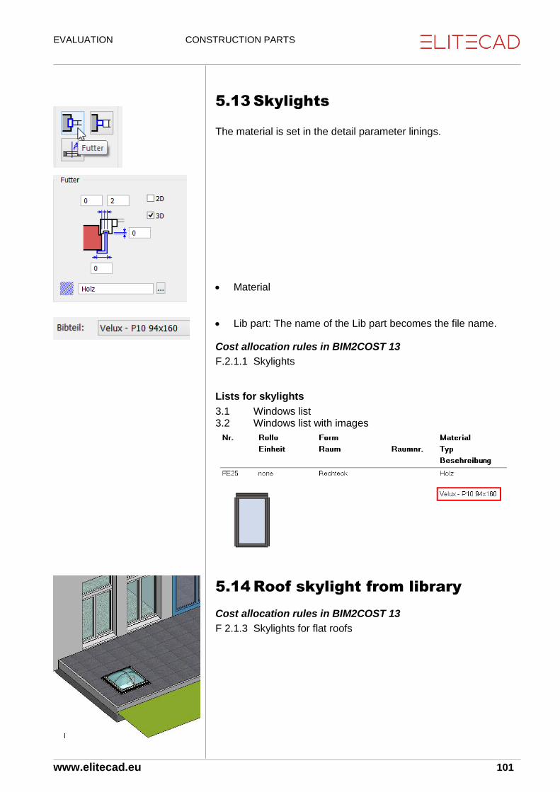
EVALUATION CONSTRUCTION PARTS
www.elitecad.eu 101
5.13 Skylights The material is set in the detail parameter linings.
Material
Lib part: The name of the Lib part becomes the file name.
Cost allocation rules in BIM2COST 13
F.2.1.1 Skylights
Lists for skylights
3.1 Windows list 3.2 Windows list with images
5.14 Roof skylight from library
Cost allocation rules in BIM2COST 13
F 2.1.3 Skylights for flat roofs

EVALUATION CONSTRUCTION PARTS
www.elitecad.eu 102
5.15 Doors
CAD allocates the doors to the individual rooms.
The fire protection information is exported to the database and shown in the lists.
Doors in external walls are automatically evaluated as external.
Cost allocation rules in BIM2COST 13
The following settings are used in BIM2COST:
Material
Internal/External
Opening type
Stop
Shape
Frame
Fire protection E 3.2.1 External doors, external gates in timber E 3.2.2 External doors, external gates in metal G 1.4.1 Framed doors G 1.4.2 Casement doors G 1.4.3 Lined doors G 1.4.4 Sliding doors G 1.4.5 Fire protection doors
Lists for doors
3.3 Door list 3.4 Door list with images

EVALUATION CONSTRUCTION PARTS
www.elitecad.eu 103
5.16 Stairs
Stair evaluation
Materials
The material is evaluated for stairs using the following sequence: 1. Stair flight plate 2. Cheek 3. Stair finish The material is listed in the lists. Using this, allocation to the correct cost component is possible in BIM2COST. The material can be changed in BIM2COST in the properties window.
Cost allocation rules in BIM2COST 13
C 4.2.x Stairs by material
Lists for stairs
Listing by material Detailed evaluation separately by stair type, run and landings. Individual landings are listed in the ceilings list.

EVALUATION CONSTRUCTION PARTS
www.elitecad.eu 104
Rooms and room finishes for stairs The stair undersides are height-limiting for a room. Effect:
Limiting room height: in the living space calculation, this room height is taken into account.
Room volume: The net room volume NRI (DIN 277 + ÖNORM B1800) or the net building volume NGV (SIA 416) is limited.
Room finishes: Wall finishes are limited to the side. Ceiling finishes and floor finishes are calculated for the stair landing.
Room definition for stairs The room definition for stairs must always be set in the upper storey. As an example, an extract from DIN 277: “Areas of stairs and ramps (...) are to be allocated to the level above them, insofar as they do not intersect there with other areas.” Thus no separate room definition needs to be set below the lowest stair. The space under the stair is limited in height by the stair.
Room volume calculation ( NRI or NGV)
The net room volume for stairs is always fully allocated to the upper storey in the lists.
Individual landings for multiple-flight stairs Multiple-flight stairs can also be created from individual runs. The landings between must then be created using the CAD floor function with type Stair landing. See previous section. The evaluation is then similar to the usual stair functions with landing:
Room heights and room volume limit
Ceiling finishes below landing (illustration with view upward)
Floor finishes on landing
Wall finishes interrupted for landing Individual landings are listed in the foundations and ceilings list.

EVALUATION CONSTRUCTION PARTS
www.elitecad.eu 105
Wall finishes for stairs Where stairs adjoin a wall, the wall surface (plaster) is interrupted The wall finish above the stair is calculated in the upper storey. The wall finish below the stair is calculated in the lower storey. This means it is possible to differentiate between wall finishes. The areas for wall finishes uses measured values. The wall finish for solid stairs is cut out from the bottom view to the lower edge of the stair finish. For stairs with cheeks, the wall finish and open stairs are separated at the bottom edge of the step. However, if in BIM2COST the wall finish is to be calculated as continuous for the stairs, then this can be performed using an allocation rule: Cheek length times stair depth. Alternatively, the stair can be drawn with a minimum spacing to the wall.
Ceiling finishes for stairs Ceiling finishes are calculated using the measured area below stairs and storey/level floors and stair landings.
Floor covering finishes for stairs Stairs are evaluated to the lower storey. Accordingly, a room definition must be set in the upper storey.

EVALUATION CONSTRUCTION PARTS
www.elitecad.eu 106
5.17 Banisters
Option external/internal
Cost allocation rules in BIM2COST 13
F 2.2.1 Banister, external G 5.4.2 Banister, internal
Lists for banisters
2.4.61 Banister

EVALUATION CONSTRUCTION PARTS
www.elitecad.eu 107
5.18 Installations
Library parts from the installation CD
Library parts (2D model for objects) are described as installations.
Plan graphic symbols etc. are not described as installations.
BIM2COST
Library parts from the EliteCAD library are evaluated. For the standard allocation rules, the marking libname is used.
Own installations
Menu Layout > Installation
Describe the object as an installation Menu Layout > Installation
Type
For the evaluation of own library parts, it is advised to define the following:
Order (becomes the layer name)
Name
Description
Material Note: Classes (#C), groups (#G), level (#L) are only available if in the CAD the option select using group/class/level is enabled for Options > Work parameter(s) > Edit (not recommended).

EVALUATION CONSTRUCTION PARTS
www.elitecad.eu 108
Own installations as library parts
Menu Extras > Define LIB. PART
For own library parts, these are automatically defined as installations when saving if the option “Adjust to floor height” is selected. When saving, the library name with the marking bibname (save path with file name) is added automatically. Similarly, the library part is given the marking object with value equipment.
Cost allocation rules in BIM2COST 13
Cost component D Engineering and G Extension
All cost components counted as a unit, e.g. D 8.1 Fixing device, appliance (sanitary)
G. 5.1 Fitted cupboard, shelf with the underlying element type groups
G. 5.2 Fitted kitchen, with the underlying element type groups: G 5.2.1 Furniture F 5.2.2 Cover G 5.2.3 Appliances
Notes for kitchen
For the standard rules in BIM2COST, via the room name there is an allocation to G 5.2 Fitted kitchen
Lists for installations
4.5 Installations by room

EVALUATION CONSTRUCTION PARTS
www.elitecad.eu 109
5.19 Help functions
Room separator Marking: object, value roomsep. Room separators may not be set along room-separating walls. No wall finish (plaster) is calculated along room separators. Accordingly, walls are to be defined as room-separating.
Height definition New feature for EliteCAD AR13: The height definition is an invisible roof. It is set similarly to the normal roof:
Roof thickness= 0.
3D colour = 0
Hatching with Pen 0 This hatching is only shown under the height in accordance with Options > Work parameters > Drawing > Section parameters for floor plan imaging
In the CAD, the hatching makes it easier to select and identify the set height limit. The basic setting of EliteCAD AR13 contains a hatching parameter for this, parallel or invisible. Height definitions (roofs) with these settings are not evaluated.
Height definition for non-vertical glass elements. If the room and/or building volume is to be limited above a glass element, a height definition must be set.
Height definition for skylights from library The skylights present in the library are not height-limiting. A height definition must be set. Skylights created using the skylight function do not require a height definition

EVALUATION CONSTRUCTION PARTS
www.elitecad.eu 110
Height definition for external rooms See also course example Room volume for external rooms
DIN 277 + ÖNORM B1800, Area/Area type c:
Set height definition on upper edge of the limiting construction parts (banister, parapet etc.)
SIA 416:
Set height definitions on upper edge of floor and the limiting construction parts (at floor height and on wall parapets). SIA 416 does not recognize external room volume for external rooms, but construction volume and room areas and construction areas. However, if the height definition is deliberately set higher, then an external net area volume (ANGV) and external building volume (AGV) is calculated (no standard descriptions).
Notes The volume is always determined using the storey height in
accordance with the structure settings. This is only limited by a storey or level floor, roof or a height definition.
If only max. room height is defined for the room description, the volume above this up to the storey height is calculated as part of the construction volume (suitable for installed ceilings).
A height definition limits both volumes to this height.

EVALUATION CONSTRUCTION PARTS
www.elitecad.eu 111
6. Adding additional properties
Description Using the copy parameters function, the property description can be added to all construction parts. This property is then output in the lists. This property can be used in BIM2COST for allocation rules.
Type The property is later implemented. The lists are already prepared for this property.
Examples
Description for windows Model: Structure Basement
Copy parameters
Select window
“None” button
Enable description
Enter description
“Individual” button
Select the same window and additional windows if desired.
Cancel function Evaluation model list:

EVALUATION CONSTRUCTION PARTS
www.elitecad.eu 112
Description for skylights
The library name is transferred by the program as the description.
Description for roof truss
Fascia boards
In the model, the roof edges are recorded using the roof truss functions. Beam function with description fascia board Rafter function with description fascia board
Description for girders Girder in basement

EVALUATION CONSTRUCTION PARTS
www.elitecad.eu 113
7. Defining 3D objects as a
construction part
7.1 Introduction Customary 3D objects such as boxes, 3D surfaces etc. can be defined as a construction part. The scope of this function is still at the start of development, and will be expanded and optimised in further CAD updates. In the first release of EliteCAD AR13, therefore, most items must be set manually. For this, some mandatory entries are also required. Therefore, this scope of function is primarily suitable for construction parts which cannot be created with the normal construction part functions. The entries are saved and can also be used in BIM2COST for the evaluation.
7.2 Tools
Property windows Menu View > Window > Properties
Ctrl + 6 or Strg. + 6
The property window is empty
Procedure
Select 3D object. With few exceptions, the construction parts created using the construction part functions cannot be used.
Add a property Different definitions can be made using the dataset window
Dataset: A saved setting can be transferred
Evaluation o Object types
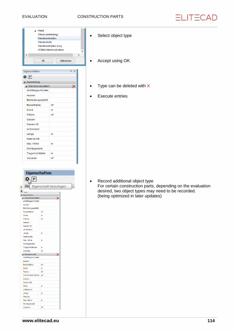
EVALUATION CONSTRUCTION PARTS
www.elitecad.eu 114
Select object type
Accept using OK
Type can be deleted with X
Execute entries
Record additional object type For certain construction parts, depending on the evaluation desired, two object types may need to be recorded. (being optimized in later updates)

EVALUATION CONSTRUCTION PARTS
www.elitecad.eu 115
Measurement functions In order that the measured values can be copied and input into the entry fields, CAD should be switched to the metre unit
Volume measurement function
Menu Info > Measure > Volume
Construct 3D object individually
Calculate
Copy calculated value for volume
Enter copied value in the property window.

EVALUATION CONSTRUCTION PARTS
www.elitecad.eu 116
Dataset
Save property as dataset In order for the input values to remain stored for later model variants, they can be saved as a dataset.
Edit dataset
Copy the current properties into the new window
Enter and save the dataset name
The input values are saved with this name Now the saved dataset is available for later entries (including for other models).
Add a saved dataset (properties) to an object Select 3D object.
Add a property
Select the saved dataset

EVALUATION CONSTRUCTION PARTS
www.elitecad.eu 117
Edit and delete dataset Saved datasets can be edited in the properties window. The dataset is selected in the pull-down menu. The dataset can be deleted using the delete button. Changed entries can be saved using the save symbol. All input values can be altered.

EVALUATION CONSTRUCTION PARTS
www.elitecad.eu 118
7.3 Application The following instruction applies for EliteCAD AR13 without updates. Optimizations are being built into later updates which produce simplifications in the application.
Saved datasets When EliteCAD AR13 is installed, prepared datasets for various construction parts are also supplied. These contain values which need to be modified. For quantities, in most cases the value 99 is entered; this needs to be modified. It is not necessary to fill every value field. These are therefore empty in the datasets.
Requirements
Multilayer construction parts from 3D objects Only one layer type may be defined per 3D object.
This means that a 3D object must be created for each layer type for multilayer construction parts.
Two object types are needed
Layer type (e.g. wall construction) The layer type is needed as the lists are organised by layer types. BIM2COST requires the layer type for allocation to cost components.
Layer(s) (e.g. wall layer) Several layers can be added. In the lists, the layers are subordinate to the layer types.
Other construction parts from 3D objects One object type is sufficient
Construction parts from the construction part functions No further allocations can be made using this function.
Room definitions from the architecture function Room finishes and living spaces can be added. However, these are not listed in the living space verification.

EVALUATION CONSTRUCTION PARTS
www.elitecad.eu 119
7.4 Multilayer construction parts
Walls
Brick walls Select 3D object.
Add a property
Brick walls dataset
Wall construction (layer type)
External/Internal
Thickness
Surface
Trade
Material, overarching term
System-built wall Yes/No
Wall layer (layer)
External/Internal
Thickness
Surface
Trade
Material (synonym)
System-built wall Yes/No

EVALUATION CONSTRUCTION PARTS
www.elitecad.eu 120
Concrete walls
Wall construction (layer type)
External/Internal
Thickness
Surface
Trade
Material, overarching term
System-built wall Yes/No
Volume
Wall layer (layer)
External/Internal
Thickness
Surface
Trade
Material (synonym)
System-built wall Yes/No

EVALUATION CONSTRUCTION PARTS
www.elitecad.eu 121
Partition wall, system-built wall Wall facing (layer type)
External/Internal
Thickness
Surface
Trade
Material, overarching term from all layers
System-built wall Yes
Wall layer1 (layer)
External/Internal
Thickness
Surface
Trade
Material (synonym)
System-built wall Yes/No
Wall layer2 (layer)
Wall layer3 (layer)

EVALUATION CONSTRUCTION PARTS
www.elitecad.eu 122
External insulation Wall facing (layer type)
Wall layer (layer)

EVALUATION CONSTRUCTION PARTS
www.elitecad.eu 123
Foundation Foundation construction (layer type)
Thickness
Measured surface
Surface
Incline
Material, overarching term
Volume
Foundation layer (layer)
Thickness
Measured surface
Surface
Incline
Material
Volume

EVALUATION CONSTRUCTION PARTS
www.elitecad.eu 124
Concrete slab Floor construction (layer type)
External/Internal
Thickness
Measured surface
Surface
Incline
Trade
Material, overarching term
Volume
Wall layer (layer)
External/Internal
Thickness
Measured surface
Surface
Incline
Trade
Material
Volume

EVALUATION CONSTRUCTION PARTS
www.elitecad.eu 125
Slab facing
Floor facing (layer type)
External/Internal
Thickness
Measured surface
Surface
Incline
Material, overarching term
Wall layer (layer)
External/Internal
Thickness
Measured surface
Surface
Incline
Material

EVALUATION CONSTRUCTION PARTS
www.elitecad.eu 126
Additional floor finish area for existing room definition Note: The room definition is the only architecture function where additional object types can be added. The selection is, however, reduced to the room object types. No saved datasets can be called up
Select existing room definition
Floor finish layer (layer)
External/Internal
Thickness
Measured surface
Surface
Incline
Material
Floor covering finish
External/Internal
Thickness
Measured surface
Surface
Incline
Material, overarching term

EVALUATION CONTROL FUNCTIONS
www.elitecad.eu 127
8. Control functions
8.1 Check room contours
Notes on room-separating functions
In order for the room contours to be determined by CAD, the following rules must be respected:
Room-separating elements must not overlay one another.
No room separations along room-separating walls or room-separating glass elements.
No room-separating glass element above room-separating walls. The glass element should then not be defined as room-separating.
Check evaluation contours Menu Extras > Evaluation > Check evaluation contours
Toolbar Evaluation > Check evaluation contours
This function creates new contours in the room-check-contours layer.
Each storey must be constructed separately.
All layers are hidden. The CAD shows only the created layers “room-check-contours” and “error”.
Each individual contour corresponds to a room contour. If the CAD has succeeded in correctly determining the room contour, the contour corresponds to a closed polygon.
If a room description has been set previously, the polygon is hatched.
Incorrect contours can be tested using the function check 2D model.
For room descriptions that are duplicated or that cannot be allocated to a room contour, the problem is indicated using a red triangle with a diagonal line.
Incorrect contours are displayed in yellow and are located in the error layer.
The perimeter contour must lie outside all room contours (on the external side of the building). This contour corresponds to the storey floor area (gross storey area). Multiplied by the storey height, this produces the gross room volume. Where the perimeter contour does not include all room contours, negative values are evaluated.
Delete the room-check-contours + error patterns with delete image (unless additional layers were constructed).
This function is similarly useful to display cavities. Non-hatched areas for cavities have no room definition and are then allocated to the construction area and to the construction volume.

EVALUATION CONTROL FUNCTIONS
www.elitecad.eu 128
Example of duplicated room definition
Example of superimposed room-separating walls
Check room contours: Duplicate room definition is displayed White error contours arise if walls are superimposed.

EVALUATION CONTROL FUNCTIONS
www.elitecad.eu 129
Example of error with room separators
Here room separators intersect. They would need to be interrupted at the crossing point. Using yellow error contours, the display indicates that an error involving room separators is present.

EVALUATION CONTROL FUNCTIONS
www.elitecad.eu 130
Stripping out evaluated contours
Error search
Room separators along or in room-separating construction parts
Several superimposed room separators create errors.
Room separations along room-separating walls, and glass elements must be deleted.
Show room separators
Menu Edit > Select > Identification Marking object, Value roomsep Use [RETURN] [RETURN] to exit selection and display using the Show Selection button.
Unclean wall junctions
The check evaluation contours function makes open (top right) and overlapping objects (below) visible. These errors can also lead to consequential errors in other room areas. For that reason, unclean wall junctions must firstly be stripped out.

EVALUATION CONTROL FUNCTIONS
www.elitecad.eu 131
Room-separating objects located above one another
Example. Room-separating wall above a room-separating base with an integral room-separating glass element. Result: In part, the room-separating effect is revoked. This causes the room contours to be lost. Correction: Here the upper wall and the glass element must not be defined as room-separating.
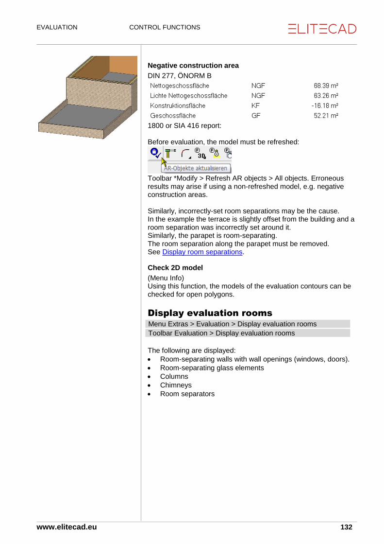
EVALUATION CONTROL FUNCTIONS
www.elitecad.eu 132
Negative construction area
DIN 277, ÖNORM B
1800 or SIA 416 report: Before evaluation, the model must be refreshed:
Toolbar *Modify > Refresh AR objects > All objects. Erroneous results may arise if using a non-refreshed model, e.g. negative construction areas. Similarly, incorrectly-set room separations may be the cause. In the example the terrace is slightly offset from the building and a room separation was incorrectly set around it. Similarly, the parapet is room-separating. The room separation along the parapet must be removed. See Display room separations.
Check 2D model
(Menu Info) Using this function, the models of the evaluation contours can be checked for open polygons.
Display evaluation rooms Menu Extras > Evaluation > Display evaluation rooms
Toolbar Evaluation > Display evaluation rooms
The following are displayed:
Room-separating walls with wall openings (windows, doors).
Room-separating glass elements
Columns
Chimneys
Room separators

EVALUATION CONTROL FUNCTIONS
www.elitecad.eu 133
8.2 Expanded control functions
Menu Extras > Evaluation > Quantities manager
Toolbar *Create new AR objects
Toolbar > Evaluation > Quantities manager
In quantities manager: Rules/Configuration button. In the options list, the option “Display calculation result” is set to 1. In the evaluation, new 3D objects are created for the “additional CAD layer”: If the option is reset to 0, these objects are deleted for the next evaluation. Model without additional control layer Model (German model) with additional control layers:
Room-limiting areas
Storey-limiting areas

EVALUATION CONTROL FUNCTIONS
www.elitecad.eu 134
Control layer for room volume
Control layer for room-limiting areas
The net volume of rooms is shown using 3D surfaces. These are only visible in the solid model (illustration) or wireframe model. The surfaces are open for openings.
Control layer for storey-limiting areas
The gross room volume of buildings is shown using 3D surfaces. These are only visible in the solid model (illustration) or wireframe model. The surfaces are open for openings.
Room box diagram for rooms
By comparison with the room-limiting areas layer, in quantities manager it is possible to switch to room box display from a previous solid model display.

EVALUATION EVALUATION
www.elitecad.eu 9-135
9. Evaluation
9.1 Evaluation in DB
Menu Extras > Evaluation > Evaluation in DB
Toolbar Evaluation > Evaluation in DB
Quantities manager > Evaluation in DB
Before evaluation, the model must be stripped out using refresh AR objects (only possible in EliteCAD).
The value settings required for the evaluation are imported before the calculations.
EliteCAD AR13 + BIM2COST 13: All (including non-displayed) construction parts are evaluated and exported to the MySQL database.
Docuplan: with the option enabled, the document texts are allocated to the construction parts.
Per project, several models can be evaluated. The model name (drawing name) is also saved to the database, along with the project name.
9.2 Docuplan
Docuplan is used to monitor the evaluation.
The docu-texts are allocated to the evaluated objects.
Docu-texts are listed in the reports.
Requirement for displaying docu-texts:
Work parameter(s) > Evaluation Enable “Display docu-texts”
Select text parameter(s) The docu-text can be modified in the text column. The docu-texts are written to the docu-text layer.

EVALUATION EVALUATION
www.elitecad.eu 9-136
9.3 Object types In quantities manager, the object types can be selected and viewed in the CAD. For the object types, the description is supplemented with the docu-text.
CAD object - Object types - Docu-text
CAD object The CAD object is selected in the CAD. When to docu-texts option is switched on (see previous chapter), it is assigned a docu-text during evaluation. In the CAD, this is written into the floor plan (WA57). When a CAD object is selected in the CAD, the quantities manager displays the object types of which the object consists. In the index of values and attributes, nothing is displayed.
Object types A detailed listing of all object types is listed in the User Manual.
Main object type
Main object type and CAD object are generally identical, but the main object type is selected in the quantities manager. In the CAD, the object types are shown in accordance with the Colour setting for object types (document end). Some values, e.g. the total thickness (thickness) of this main object type are listed in the “values and attributes” window.
Sub-object types
Layer (e.g. wall layer)
A layer is a sub-object type. The docu-text is supplement in the quantities manager with the layer number. (WA57/2). The results are listed for the “values and attributes”. For walls, sometimes this includes the associated trade. The detailed calculation is listed in the “formulae” index. The document number is supplemented with the section number. (WA572.1)

EVALUATION EVALUATION
www.elitecad.eu 9-137
Construction and sublayer (e.g. wall construction)
For multi-layer construction parts, the layers described as “load-bearing” are evaluated as load-bearing. For instance, for walls the supporting layer is evaluated as wall construction. For wall constructions, deduction audits for openings are undertaken and shown in the CAD. For a wall opening, the displayed area is crossed through if it is smaller that defined in the options (walls + plaster). Sublayers of room finishes may comprise several layers (only BIM2COST).
Facing and covering finish (e.g. wall (facing))
For multi-layer construction parts, the layers described as “facing” are evaluated as facing. For room finishes, the visible finishes are evaluated as a covering finish. Facings, unlike constructions, are measured on the surface. For a wall opening, the displayed area is crossed through if it is smaller that defined in the options (walls + plaster). Facings may comprise several layers. Multiple layers are possible for covering finishes (only in BIM2COST).

EVALUATION LISTS AND OPTIONS
www.elitecad.eu 138
10. Evaluation options and lists
Lists in EliteCAD
Menu Extras > Evaluation > Reports
Toolbar > Evaluation > Create and print lists
Quantities manager > Create and print lists
Lists in BIM2COST
Evaluation management > Create and print lists
General
Requirement
In order that a model can be evaluated correctly, this must first be cleaned up using refresh AR objects.
Evaluation EliteCADAR13
An already-evaluated model (drawing name) does not need to be evaluated again. The evaluation remains stored in the database. If the model is modified, however, a new evaluation is required. Recommendation: New model name, that can be compared with the old model.
Evaluation BIM2COST 13
When a model is first imported, it is evaluated automatically. If this is imported again later, it is checked following modifications to the model and updated in BIM2COST together with the modifications made in the last session.
Properties description and type
For the construction parts lists, the property description and type is output.
Project management Menu Extras > Evaluation > Project Management
See also User Manual, Chapter 14.1 The projects and associated evaluated models are listed in project management.
Deleting models
Individual models or whole projects can be removed from the database using the delete button. The reset database button causes all models to be removed from the database.

EVALUATION LISTS AND OPTIONS
www.elitecad.eu 139
10.1 Print lists
EliteCAD Menu Extras > Evaluation > Reports
Toolbar > Evaluation > Create and print lists
Quantities manager > Create and print lists
Requirement
In order for the lists overview to be opened, the model must be imported and evaluated in the CAD.

EVALUATION LISTS AND OPTIONS
www.elitecad.eu 140
Change options
List in RTF format
After the list has been opened, it can also be saved in RTF format using the RTF button, so that the list can then be edited in a text processing program (e.g. Word).
Text changes
Using the texts button in the lists overview window, the texts used in the lists can be altered. The text variable (text descriptor) is in the left column. The text for this variable can be amended in the right column.
List header / company name
The text for the company letterhead is set using the master data for the INI values.
INI values For the INI values, the company data for List print-outs is entered. For Id 7, the font size in the master data window is modified.

EVALUATION LISTS AND OPTIONS
www.elitecad.eu 141
10.2 List content
1.1 Areas and volumes
1.101 Areas and room volumes in accordance with DIN 277 (2005 edition), ÖNORM B1800 and SIA 416.
Room list
Note In order that the lists can be printed out to comply with the standards, the use types and areas must be input for the room definitions in accordance with the current standards DIN 277, ÖNORM B1800 and SIA 416. See Entries in room definition. The room definitions for stairs must always be set in the upper storey. See Area types for stairs
Rough and net areas, room volume.
Totalling of rooms by use types. Germany + Austria: Totalling of rooms by areas.
Rooms with non-defined areas (a, b or c) are allocated to Area a for standards DIN 277 and ÖNORM B1800 (covered and enclosed on all sides)
Manual perimeter contours for external areas (CH: ANF, AVF, AFF; DE + AT: Areas b + c) take precedence over information in the room definition.
Air spaces have no surfaces, but do have room volume.
Cavities defined using the room description as construction areas are not listed, but are added to the construction area.
Rooms for stairs must always be defined as a “normal room” in the upper storey.
Unlabelled rooms are not listed and are calculated as part of the construction area.
1.1.02 Areas and room volumes in accordance with DIN 277 (2005 edition), ÖNORM B1800 and SIA 416 (totals list).
Totals list
The construction areas are calculated from the difference between the storey areas and the room areas.
SIA 416
Totals of all standard use types
ÖNORM B1800 + DIN 277
Totals of areas and room volumes by Areas a, b and c
1.1.91 Plane(s) verification rough dimensions
Rough part areas with detailed calculation
The plane(s) verification list is also created without a previous verification.

EVALUATION LISTS AND OPTIONS
www.elitecad.eu 142
1.2.01 Living spaces with measured deduction for plaster (woFlV)
Rough and net areas.
Evaluation as living space, taking account of reduction factors for low room heights in accordance with WoFlV.
The set values (Options room) for limit heights are taken into account during evaluation.
Window niches are taken into account in accordance with Options room if the set value is greater than 0. (Germany - Living Space Ordinance (WoFlV) 0.13m)
The living space percentage is read from the room description.
Rooms where the living space percentage field was not defined are evaluated using the living space percentage 100%.
Rooms without room definitions are not evaluated.
1.2.91 Living space verification of areas
Net part areas with detailed calculation, broken down by limit heights
The living space verification list is similarly created without a previous graphical living space verification.
1.6 Facade
1.6.01 External wall areas
Object type external surface without deduction audit

EVALUATION LISTS AND OPTIONS
www.elitecad.eu 143
2. Framing
2.1 Walls
Trade /work type
In order for the allocation to a trade or work type is made correctly, the options and materials for walls must be set.
Breakdown, measurement type
Breakdown using the layer types wall construction, non load-bearing wall construction, wall facing subconstruction and wall facing
Layers in the same layer type are measured together in some cases.
Wall facings are measured on the surface.
The other layer types are measured using the middle of the layers.
2.1.01 Brick walls by storeys/structures
Deduction audit in accordance with the options setting. See Brick walls and wall layers.
Materials in accordance with the options setting. See Materials for brick walls.
The deduction limit values can be modified. After this, a fresh evaluation must be performed, and a check is made as to whether an opening is being over-measured and the extent of the over-measurement.
The walls are output both as a capacity measure and as a surface measure. The deduction audit is performed separately.
The area measurement is taken in the middle of the wall.
For multi-layer walls, the layers are listed separately by material. Wall layers which according to the material name do not belong to the brick wall trade are listed in the other lists.
All layers have a docu-number and can be visualized in quantities manager by selecting them. The docu-number starts with the docu-text WA, the wall number, and ends with the layer number and the section number, e.g. WA 1/1.1.
2.1.02 Brick walls by material
2.1.04 Concrete walls by storeys/structures
Deduction audit in accordance with the options setting. See Concrete walls.
Materials in accordance with the options setting. See Materials for concrete walls.
Remainder as for brick walls (see above).
2.1.05 Concrete walls by material

EVALUATION LISTS AND OPTIONS
www.elitecad.eu 144
2.1.11 Drywall construction walls by storeys/structures
(Plaster walls)
For multi-layer walls, the object type wall (wall facing) is measured in total with all wall layers. The area is measured on the wall axis side.
Deduction audit in accordance with the options setting. See Walls drywall construction (plaster walls, drywalls).
Materials in accordance with the options setting. See Materials for drywall construction walls.
2.1.12 Drywall construction walls by material
2.1.13 System-built walls drywall construction by storeys
Partition walls should be defined as a system-built wall. Then all layers are summarized and measured on the surface of the wall
2.1.14 System-built walls drywall construction by type
2.1.21 External insulation by storeys
Composite thermal insulation system (Wärmedämmverbundsystem, WDVS)
All wall layers for external insulation must be defined as facing. The object type wall (wall facing) is measured with all wall layers on the external side.
Deduction audit in accordance with the options setting. See External insulation.
Materials in accordance with the options setting. See Materials for external insulation.
2.1.22 External insulation by material
2.1.31 Other external walls by storeys
All wall layers that are not allocated to a trade or work type are listed here.
A deduction audit following the setting for brick walls occurs only if the materials are listed in the options for Different wall materials.
2.1.32 Other external walls by material
2.1.41 External system-built walls by storeys/structures
Walls pre-fabrication. Walls must be defined as a system-built wall. Then all layers are summarized and measured on the surface of the wall
2.1.41 External system-built walls by type
EVALUATION LISTS AND OPTIONS
www.elitecad.eu 145
2.1.51 Other internal walls by type
2.1.52 Other internal walls by storeys/material
2.1.53 Other internal walls by material
2.1.61 Other internal system-built walls by storeys/structures
Walls pre-fabrication. Walls must be defined as a system-built wall. Then all layers are summarized and measured on the surface of the wall
2.1.61 Other internal system-built walls by type
2.1.91 All wall layers by storeys/structures
No grouping by layer types
Each layer is calculated separately
2.1.91 All wall layers by material
2.2 Foundations and slabs
Breakdown, measurement type
Breakdown by layer types floor construction, insulation (non load-bearing), floor sub-construction/dead floor and floor facing
Layers in the same layer type are measured together in some cases.
The layer types are measured on the upper surface
The bottom layer type is measured on the lower surface
2.2.01 Foundations
Surfaces and volume with calculation verification.
2.2.02 Concrete slabs
Surfaces and volume with calculation verification.
There is automatic allocation to the trade or work type concrete slabs if the materials are listed for the wall layer types in situ concrete construction. See also Trades (work types).
2.2.03 Concrete roofs
CAD slabs defined as a roof and belonging to the trade concrete slabs
2.2.03 Various slab constructions and facings
CAD slabs which are not allocated to the trade or work type concrete slabs.
Dead floors
Slab facings using the CAD slab function
Slab facing subconstruction

EVALUATION LISTS AND OPTIONS
www.elitecad.eu 146
2.2.21 Special slab facings (hollow ceiling type)
Facings and subconstructions created using the CAD slab function type hollow ceiling
2.2.91 All ceiling layers
No grouping by layer types
Each layer is calculated separately
2.3 Roofs
Breakdown, measurement type
Breakdown by layer types roof construction, roof insulation (non load-bearing), roof subconstruction, roof skin and soffit
Layers in the same layer type are measured together in some cases.
The layer types are measured on the upper surface
The bottom layer type for the facing type is measured on the lower surface as a soffit.
2.3.01 Roof planes and edges
Roof planes in true area measurement and roof pitch.
All roof edges and roof cut-outs in linear measure.
Listing by material
CAD roofs and CAD slabs which are defined as roof and not allocated to the trade or work type concrete slabs are listed.
2.3.91 All roof layers
No grouping by layer types
Each layer is calculated separately

EVALUATION LISTS AND OPTIONS
www.elitecad.eu 147
2.4 Construction parts 2nd section
2.4.01 Construction timber
Cross-sections, length, surfaces and volume.
The linear measure for all beams corresponds to the beam length before the beam ends have been worked.
Switzerland: Cross-sections under 100 cm2 in the linear measure in accordance with the limit value setting Options construction timber Cross-sections over 100 cm2 in capacity measure Switzerland: Over-lengths (8 m) in accordance with setting Options construction timber
2.4.11 Columns
Cross-section shape
Linear and volume measure
2.4.21 Girders
Girders with the CAD function girder and with the CAD function wall, type girder.
Cross-section shape
Linear and volume measure
2.4.31 Stairs
Stairs are listed grouped by type. The evaluation covers:
The listing, separated by material or by the main material: If the stairs have a flight plate, this material takes precedence. Secondly, the material for the cheek is used, and if no stair cheek is present either, then the material for the step is definitive for the stair material.
Steps: Number, slope, edge length, covering thickness and tread area
Entrances and exits. The volume is already calculated in the stair runs.
Cheeks: Length horizontal and diagonal
Stair flight plates: Slope, width, depth, height, length, area on the underside, and volume
Landings: Width, length, depth, area, volume, covering thickness, cheek length and area on the underside.
2.4.41 Chimneys
Materials, shape and height
2.4.51 Drainage
Only the drainage created using the drainage module is listed.
The listing is separated by pipes and the shaped parts by the material
Listing for shafts

EVALUATION LISTS AND OPTIONS
www.elitecad.eu 148
2.4.61 Banisters
2.4.71 Free objects
3D objects defined using the function Define 3d objects as construction part, type “Free Object".
3. Openings
3.1 Windows list
Windows and glass elements
Width, height and area for architectural lighting and frames
Germany + Austria: grouped by frame size
Switzerland: grouped by architectural lighting.
Parapet height, shape and opening type
For window combinations with several sections, the opening types are listed separately, separated by commas.
Material and roller shutter box/gallery
Room allocation
Windows which are not allocated to any room are listed without an indication of room.
3.2 Windows list with images
In addition to the normal windows list, the window graphic is created.
The opening type is only displayed if this is set in the window parameter > Tool for window settings / muntins > Opening symbol.
When this list is initially selected, the graphics are calculated (this therefore takes a certain time).
3.3 Doors
Frame aperture and wall aperture
Doors: Door type, material, thickness, hinge side and fire protection class.
Wall thickness and room allocation (door hinge side or door opened)
Doors to external rooms are always allocated to the internal room.
3.4 Door list with images
In addition to the normal doors list, the graphic of the floor plan is created.
When this list is initially selected, the graphics are calculated (this therefore takes a certain time).
3.5 Windowsills, external
External windowsills created with the window
3.6 Windowsills, internal (ledges)
Internal windowsills (ledges) created with the window.

EVALUATION LISTS AND OPTIONS
www.elitecad.eu 149
4. Rooms
Breakdown, measurement type for room finishes
Breakdown by layer types covering finish and covering finish subconstruction. In the floors list, the Swiss specialist term “Unterlagsboden” (subfloor) is used for the subconstruction. The subfloor contains all layers in the subconstruction (screeds, insulation, etc.)
Layers in the same layer type are measured together in some cases.
The layer types are measured on the upper surface
Subconstructions can be created for wall and ceiling finishes only in BIM2COST
4.1 Floor finishes
4.1.1 Floor finishes by unit
Sorting and totalling by unit (apartment), where the unit field is not empty in the room description. Rooms for units may be distributed in the same structure over several storeys.
Rooms defined as air space or construction area are not listed.
Areas with calculation formulae, for stairs for steps and landings. See also Area types for runs of stairs and landings and Floor covering finishes for stairs
Areas separated by material. In later versions, with scope.
4.1.2 Floor finishes by unit (totals list)
Room listing per unit
4.1.3 Floor finishes by material
4.1.4 All floor finish layers
No grouping by layer types
Each layer is calculated separately

EVALUATION LISTS AND OPTIONS
www.elitecad.eu 150
4.2 Wall finishes
4.2.1 Wall finishes by unit
Sorting and totalling by unit (apartment), where the unit field is not empty in the room description. Rooms for units may be distributed in the same structure over several storeys.
Rooms defined as construction area are not listed.
The height is measured between the lower edge of the floor to the maximum room height.
The reduction on the roof through offset for insulation and the depth of the insulation is taken into account.
Calculation and deduction audit for areas in accordance with Options wall finish. For wall finishes on stairs, see also Area types for runs of stairs and landings and Wall finishes for stairs
Listing, sorted by base for the finish and material
4.2.2 Wall finishes by unit (totals list)
Room listing per unit
4.2.3 Wall finishes by material
4.2.4 All wall finish layers by material
No grouping by layer types
Each layer is calculated separately

EVALUATION LISTS AND OPTIONS
www.elitecad.eu 151
4.3 Slab finishes
Note EliteCAD calculates the slab finishes for slabs at the storey and level floor of the storey located above, taking account of their height and shape (e.g. slab openings). For that reason, all storeys must be loaded for the evaluation. If no above storey is present, then the slab finishes are calculated in accordance with the room contour. Slab finishes are similarly calculated on the underside of roofs and stairs.
4.3.1 Slab finishes by unit
Sorting and totalling by unit (apartment), where the unit field is not empty in the room description. Rooms for units may be distributed in the same structure over several storeys.
Rooms defined as construction area are not listed.
Slab finishes are calculated on the underside of storey and level floors above them, roofs and stairs.
Areas with calculation formulae, for stairs the measured area on the underside of the stairs. See also Area types for runs of stairs and landings and Slab finishes for stairs
Slab finishes below pitched roofs use the measured area.
The reduction on the roof through offset for insulation and the depth of the insulation is taken into account. See also Roof.
Rooms defined as construction area are not listed.
Area and material.
4.3.2 Slab finishes by unit (totals list)
Room listing per unit
4.3.3 Slab finishes by material
4.3.4 All slab finish layers by material
No grouping by layer types
Each layer is calculated separately
4.4 Room sheet list
Room surfaces with material
Room area, room volume, marker, minimum and maximum room height.
Area type, use type and area (NF, etc.) (a,b,c)
Windows and doors, with size
Rooms without room descriptions and rooms defined as construction area are not listed.
4.5 Installation list
Listing per room of defined Installations.

EVALUATION LISTS AND OPTIONS
www.elitecad.eu 152
Lists in BIM2COST In BIM2COST, in each case the constructed model is exported to the lists.
Create and print lists Additional lists:
5. Costs
As per element method eBKP-H
6. CAD objects
Lists by various criteria Double-clicking on the text of the list title opens that list.

EVALUATION LISTS AND OPTIONS
www.elitecad.eu 153
10.3 Value settings
Value settings in EliteCAD
Quantities manager > Rules/Configuration
Value settings in BIM2COST
Evaluation management > Index of regulations > Master data
Countries and regions settings The MySQL database is constructed in such a manner that, depending on the Windows settings (System management > Region and language options), the region-specific settings and materials are used for the evaluation. For Switzerland, the materials are recorded from the materials parameters collection and from the NPK lists of standardized items. For Austria, the materials from LB-HB (Leistungsbeschreibung - Hochbau, definitions of building construction services) are recorded. For Germany, the materials from various German documents are recorded. Spelling: When allocating to overarching terms, the precise entry for the name of the material is compared. Lower case is not replaced with upper case. The beta-shaped double-s character “ß” used in Austria and Germany is not viewed as the same as the combination “ss”.

EVALUATION LISTS AND OPTIONS
www.elitecad.eu 154
Synonyms
General
Material
The overarching terms and synonyms for materials are recorded in the synonyms index (see illustration). The overarching terms are used in the rules.
Name
For the “Material” button, it is possible to switch to names. The room names are recorded there (for BIM2COST).
EliteCAD
Rules
The allocation to the work type or trade is controlled via the overarching terms for materials. Only the overarching term is recorded in the allocation rule. For an example, see Materials for brick walls.
Synonyms
To avoid every individual material needing to be recorded in the rules, they are recorded as synonyms linking to the overarching term.
BIM2COST
Rules
The allocation to the cost element is controlled via the overarching terms for materials. The allocation to the cost element is controlled via the overarching terms for names (room name).
Synonyms
To avoid every individual material needing to be recorded in the rules, they are recorded as synonyms linking to the overarching term. The same applies to names for the room name ‘kitchen’.

EVALUATION LISTS AND OPTIONS
www.elitecad.eu 155
OPTIONS
General options Result of the formula (not yet implemented) Calculation result from formulae or value from measurement Accuracy of the formula Number of decimal places to be displayed. Internally, calculations are made using one additional decimal place. Accuracy of values Number of decimal places Accuracy of angles Number of decimal places

EVALUATION LISTS AND OPTIONS
www.elitecad.eu 156
Options room Display calculation result See Height monitoring function Factor above limit height 2 for living space calculations. Factor above upper limit height Factor above limit height 1 for living space calculations. Factor under lower limit height Factor between limit heights for living space calculations. Factor between limit heights Calculate window niche as NGF for areas in accordance with SIA 416, DIN 277 and ÖNORM B1800 Minimum room size (not yet implemented) for areas in accordance with SIA 416, DIN 277 and ÖNORM B1800 Smaller rooms are not calculated as spaces. Minimum niche depth for living space calculations. Value 0 means that window niches are not calculated. For Germany, this must be set in accordance with WoFlV as 0.13. For niches to be calculated, this must be set to a minimum value, e.g.0.001. Living spaces, limit height 1 Lower limit height above upper edge of the finished floor for living space calculations. Living spaces, limit height 2 Upper limit height above upper edge of the finished floor for living space calculations.

EVALUATION LISTS AND OPTIONS
www.elitecad.eu 157
Options walls The deduction audits for openings apply for all object types for walls (wall layer, wall (wall facing), wall construction) For wall (wall facing) and wall construction, the overmeasured openings are displayed with a continuous visualization plane. Trades are managed using materials and synonyms.
EliteCAD
With deduction audits
BIM2COST
In BIM2COST, all calculations are performed using the measured dimensions (no deduction audits)
Brick walls and wall layers
Trade (work type): Brick walls Openings deduction audit for masonry using area measurement.
Materials for brick walls
Only the materials and their synonyms included in the index Object types > Masonry is listed. The materials list can be modified. The material insulation must, under some circumstances, be adapted for the particular circumstances (and possibly deleted). The name of the insulation must be different from the materials for external insulation layers and plaster walls.

EVALUATION LISTS AND OPTIONS
www.elitecad.eu 158
Synonyms
Example brick (Backstein, CH) left, brick (Ziegelstein, DE+AT) centre + right

EVALUATION LISTS AND OPTIONS
www.elitecad.eu 159
Concrete walls
Trade (work type): Concrete walls Openings deduction audit for concrete wall using volume and area measurement (only EliteCAD)
Materials for concrete walls
Only the materials and their synonyms included in the index Object types > Masonry is listed.
Synonyms
Example concrete (CH) left and DE + AT right

EVALUATION LISTS AND OPTIONS
www.elitecad.eu 160
Walls drywall construction (plaster walls, drywalls)
Trade (work type): Walls in drywall construction Openings deduction audit for drywall construction walls using area measurement (only EliteCAD)
Materials for drywall construction walls
Only the materials and their synonyms included in the index Object types > Plaster walls are listed. The name of the material used to insulate partition walls and facings in plaster must be different from the names for external insulating layers and insulation for brick walls. Here the term drywall insulation was used.

EVALUATION LISTS AND OPTIONS
www.elitecad.eu 161
External insulation
Trade (work type) external insulation Openings deduction audit for external insulation using area measurement (only EliteCAD)
Miscellaneous wall materials
No trade (work type) All layers are listed separately. The materials listed for wall layer types under “Other layers” are listed with a deduction audit (in accordance with the set values for brick walls), and the others without a deduction audit.

EVALUATION LISTS AND OPTIONS
www.elitecad.eu 162
Options CAD floors (slabs etc.)
Trades (work types):
The materials included under Object types > Wall layer types > In-situ concrete construction are valid for drawn CAD floors and CAD roofs. Trade concrete slabs. No trade is allocated to CAD floors and CAD roofs in other materials.
Concrete foundations and slabs
In the lists, lists are divided in accordance with the definitions given for CAD slabs, by:
Single foundations
Strip foundations
Foundation slab
Slabs (external and internal slab) CAD slabs with the definition roof are specially designed for users working with the Swiss cost estimation type eBKP-H and with BIM2COST. Under eBKP-H, slabs situated under external spaces or under the outer shell of the building must be defined as roof. If these slabs are to appear in the list of foundations and slabs, this must not be defined as roof. In BIM2COST, it can subsequently be defined as roof.

EVALUATION LISTS AND OPTIONS
www.elitecad.eu 163
Options roof
Concrete roofs
CAD slabs in concrete which were defined as roof CAD roofs in concrete.
Other roofs
CAD roofs not in concrete.
Options construction timber Switzerland only Excess-lengths above 8.00: Lengths above this limit value are marked and again listed in the excess-lengths breakdown. Cross-section limit value 0.01 m2 Cross-sections below this limit value are listed in linear measure in a special breakdown.
Other construction parts without room finishes
Lists
See also User Manual, Chapter 14.5
Options room finishes
Wall finish
Trade or work type: Plaster Openings deduction audit using area measurement (only EliteCAD)

EVALUATION LISTS AND OPTIONS
www.elitecad.eu 164
Wall finish thickness depending on the base New feature for EliteCAD AR13 R3 In the wall finish thickness index, the standard thickness of the wall finish is set for various bases. This means that differences in covering depth can be taken into account, including for the calculation of living space areas. The base materials (wall materials) are listed, selected from the listing in the Synonyms index. The covering depth (plaster depth column) is entered depending on the CAD setting (m, cm, mm etc.) The Add and Remove buttons can be used to modify the list.

EVALUATION LISTS AND OPTIONS
www.elitecad.eu 165
Text changes In the texts index, all texts displaying in the quantities manager can be modified.
Colour setting for object types In the colours index, the colours for displaying object types can be modified.

EVALUATION LISTS AND OPTIONS
www.elitecad.eu 166
11. Examples
11.1 Stairs with landing This example is saved in the project CAD_Object_Evaluation as Model Stair landing.d New file. Select basement storey. Create foundation slab with dimensions alongside Create concrete wall, thickness 20 cm, with height reference bottom edge of floor to ceiling.
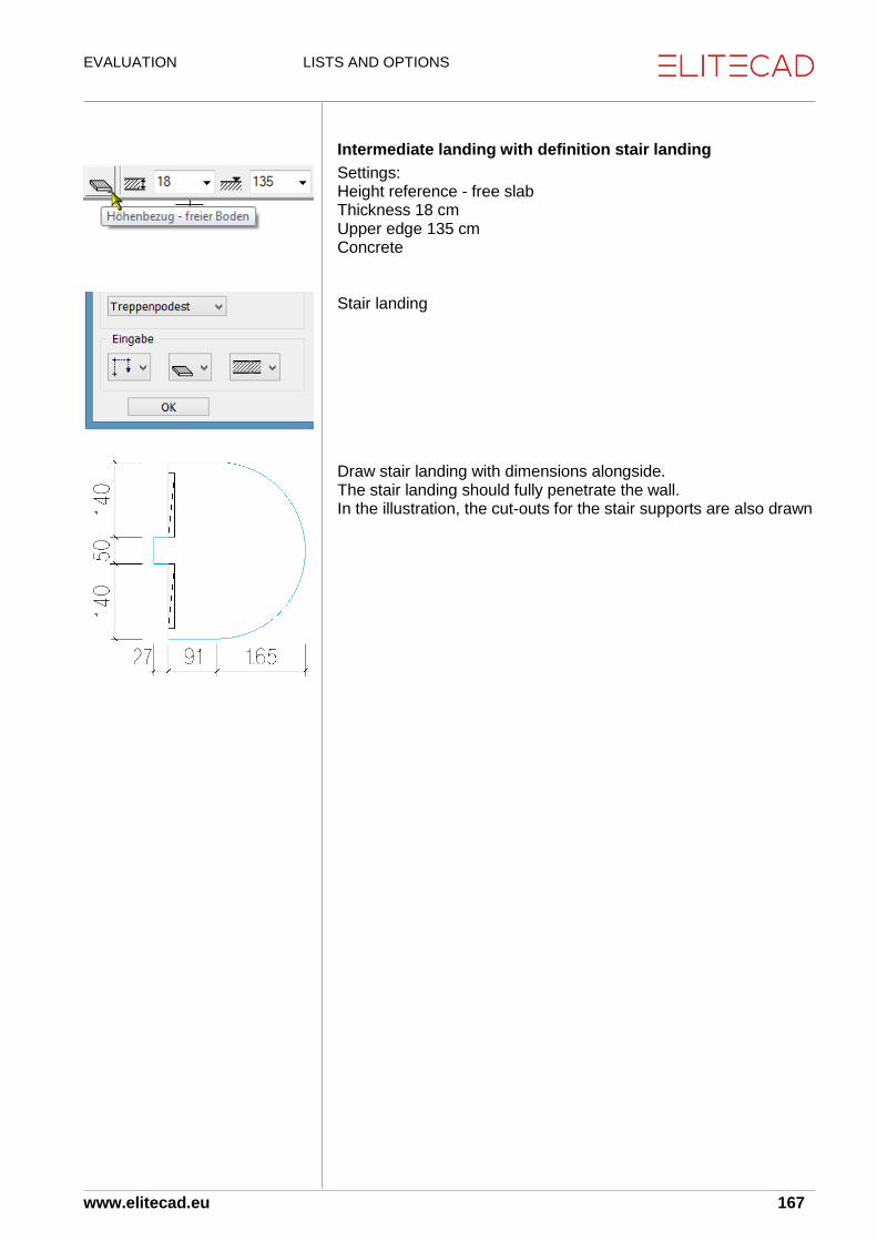
EVALUATION LISTS AND OPTIONS
www.elitecad.eu 167
Intermediate landing with definition stair landing
Settings: Height reference - free slab Thickness 18 cm Upper edge 135 cm Concrete Stair landing Draw stair landing with dimensions alongside. The stair landing should fully penetrate the wall. In the illustration, the cut-outs for the stair supports are also drawn

EVALUATION LISTS AND OPTIONS
www.elitecad.eu 168
Cutting out the wall for the intermediate landing
This work stage can be dispensed with if no cut through the stair is created. Click on the side of the wall with work plane set for surfaces, so that the working plane rotates. Create 3D box with bottom height -500 and top height 100. Illustration: side view of wall. Draw a rectangle at the height of the intermediate landing. This should be drawn slightly farther to the right than the dimensions of the landing. Using the function create wall opening, select 3D box as deduction volume. Reset work plane using select storey.

EVALUATION LISTS AND OPTIONS
www.elitecad.eu 169
Lower stair run
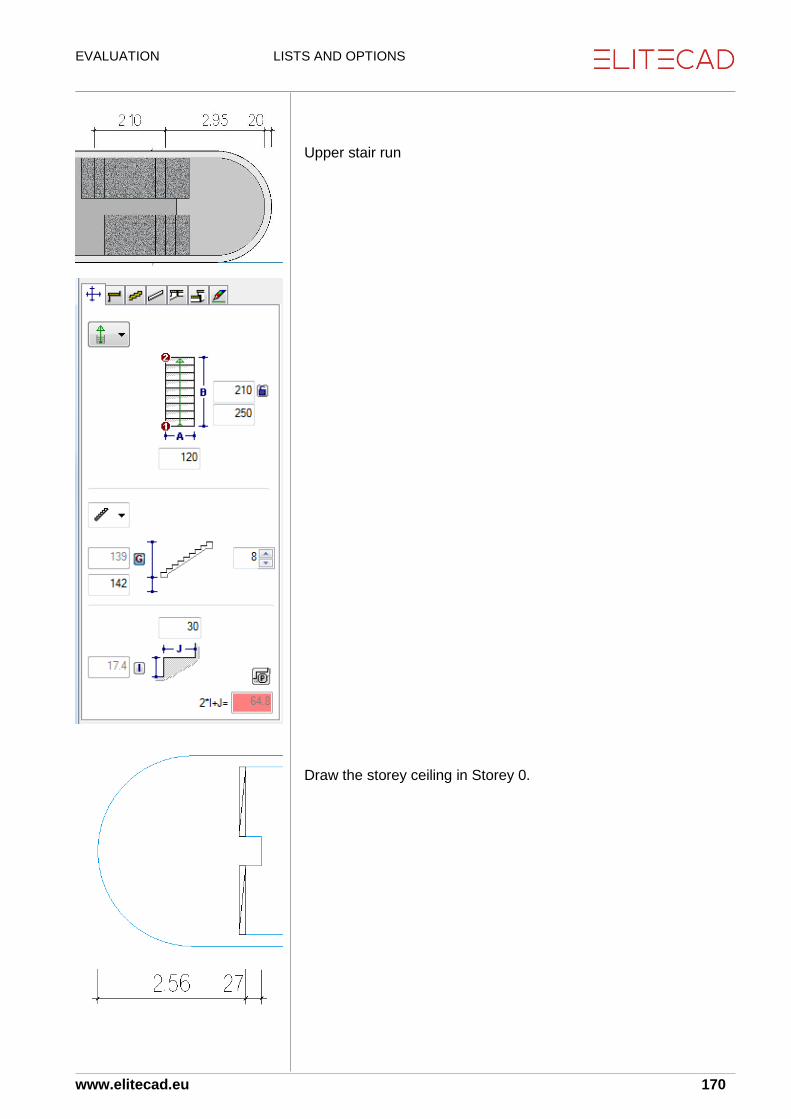
EVALUATION LISTS AND OPTIONS
www.elitecad.eu 170
Upper stair run Draw the storey ceiling in Storey 0.

EVALUATION LISTS AND OPTIONS
www.elitecad.eu 171
Repeat the process for all storeys or copy the construction parts to the upper storeys.
Room definition for stairs
Room definition in the lowest storey
In the lowest storey, a single room definition of the type “normal room” can be selected.
Room definition in the upper storeys
In the upper storeys, two room definitions are set, divided by a room separator on the storey floor edge at the transition to the stair runs.
Room definition on storey floor
Above the storey floor, a normal room definition is set with the option “normal room”.

EVALUATION LISTS AND OPTIONS
www.elitecad.eu 172
Room definition above the stair run
Standard SIA 416 allows for the area for the stairwell to be through-calculated for narrow stairwells. Accordingly, a room definition can be set above the runs of stairs (yellow area in the illustration). Setting for room definition: normal room Floor finish on stairs, Thickness 0 Wall finish Ceiling finish on the underside of the run of stairs located above, ceilings and roofs.
Room definition in the topmost storey
As in the previous section, one room definition is set above the storey floor and one above the stair run. The approach satisfies the specification in the standards that the floor plan area for stairs always belongs to the storey above.
Room definition for large stairwells
If the stairwell is of such size that this area is no longer permitted to be calculated as net area according to the standards, then in the stairwell an additional room definition with type air space must be set.

EVALUATION LISTS AND OPTIONS
www.elitecad.eu 173
Room finishes
Wall finish Wall finishes on stairs close to walls are through-calculated.
Wall finish in the lowest storey
The wall finish is calculated to the underside of stairs (and their intermediate landings) and CAD slabs with definition stair landing.
Wall finish in normal storeys
The wall finish is calculated between the stairs (and their intermediate landings) and CAD slabs with definition stair landing. In the illustration, in addition to the wall finish the room definition can be seen above the storey floor.
Wall finish in the topmost storey
The wall finish is calculated up to the stairs (and their intermediate landings) and CAD slabs with definition stair landing. In the illustration, in addition to the wall finish the room definition can be seen above the storey floor.

EVALUATION LISTS AND OPTIONS
www.elitecad.eu 174
Slab finishes
Slab finishes
The slab finish is calculated on the underside of stairs (and their intermediate landings) and CAD slabs with definition stair landing. The calculated slab finish area corresponds to the measured area.
Floor finish The floor finish is calculated to the next lower storey, as with all finishes. Measured area on stairs (and their intermediate landings) and CAD floors with definition stair landing.