course title: hvac energy conservation through cooling ... · hvac energy conservation through...
TRANSCRIPT

HVAC Energy Conservation through Cooling Water Treatment Course No: M05-013
Credit: 5 PDH
A. Bhatia
Continuing Education and Development, Inc. 9 Greyridge Farm Court Stony Point, NY 10980 P: (877) 322-5800 F: (877) 322-4774 [email protected]

HVAC Energy Conservation through Cooling Water Treatment
WATER used in air-conditioning systems may create problems with equipment, such
as scale, corrosion, and organic growths. Scale formation is one of the greatest
problems in air-conditioning systems that have water cooled condensers and cooling
towers. Corrosion is always a problem in an open water recirculating system in which
water sprays come in contact with air. The organic growth we are greatly concerned
with is algae or slime. Since algae thrive on heat and sunlight they will be a problem
in cooling towers.
The quality of water is therefore very important in determining the performance of
both chiller and cooling tower that utilize water for cooling. Improper water treatment
or no treatment at all will increase your energy consumption and operating costs
while decreasing your mechanical equipment's efficiencies and life expectancy.
This course discusses the waterside problems encountering the open re-circulation
cooling water systems, discusses how energy is dissipated from the air conditioning
equipment and how effective implementation and tight monitoring of the water
treatment programs can conserve it. The course is divided into 7 Sections:
SECTION - 1 Energy Drain in Vapor Compression Systems
SECTION - 2 Cooling Water Problems
SECTION - 3 Scale Control
SECTION - 4 Corrosion Control
SECTION - 5 Control of Organic Growths
SECTION - 6 Turbidity Control
SECTION -7 Water Treatment System Controls and Monitoring

SECTION - 1 ENERGY DRAIN IN VAPOUR COMPRESSION SYSTEMS
Before we come to the discussion on waterside problems, let’s first refresh some
fundamentals and understand little about work and energy input to the refrigeration
chillers.
The vapor compression system is the dominant system today for cooling and
refrigeration and is being used in almost all kind of application. It consists of four
components:
1. The compressor raises the pressure of the initially low-pressure refrigerant
gas.
2. The condenser is a heat exchanger that cools the high-pressure gas so that
it changes phase to liquid.
3. The expansion valve controls the pressure ratio, and thus flow rate, between
the high- and low-pressure regions of the system.
4. The evaporator is a heat exchanger that extracts heat from the air causing
low pressure liquid refrigerant to evaporate and change phase from liquid to
vapor (gas).
A schematic flow diagram of the vapor compressor system and its components is
shown below:

A pressure-enthalpy diagram or p-h diagram is often used to calculate the energy
transfer and to analyze the performance of a refrigeration cycle:
There are four processes in an ideal single-stage vapor compression cycle:
1. Isothermal evaporation process 4–1: The refrigerant evaporates
completely in the evaporator and produces refrigeration effect qrf, in Btu/lb:
qrf = (h1 – h4)
Where
h1, h4 = enthalpy of refrigerant at state points 1 and 4, respectively, Btu/lb.
The enthalpy difference between point 1 and 4 represents the heat absorbed
by the refrigerant in the evaporator or is known as “refrigeration effect”.
2. Isentropic compression process 1–2: Vapor refrigerant is extracted by the
compressor and compressed isentropically from point 1 to 2. The work input
to the compressor Win, in Btu/lb, is
Win = (h2 – h1)
Where
h1, h2 = enthalpy of refrigerant at state points 1 and 2 respectively, Btu/lb.
The nodes 2 and 1 on Y-axis represent the condensing pressure (pcon) and
evaporating pressure (pev) respectively. The pressure differential between
port 2 and 1 is “the work or energy input for compression”. The greater the

difference between the condensing pressure and evaporating pressure, the
higher will be the work input to the compressor.
3. Isothermal condensation process 2–3: Hot gaseous refrigerant discharged
from the compressor is condensed in the condenser into liquid, and the latent
heat of condensation is rejected to the condenser water or ambient air. The
heat rejection during condensation, q2–3, in Btu/lb, is
- q2–3 = (h2 – h3)
Where
h3 = enthalpy of refrigerant at state point 3, Btu/lb.
Total heat rejected by the refrigeration system to the condenser cooling
medium (h2 – h3) = Heat absorbed by the refrigerant in the evaporator
(refrigeration effect) + heat equivalent of work input during compression.
4. Throttling process 3– 4: Liquid refrigerant flows through a throttling device
(e.g., an expansion valve, a capillary tube, or orifices) and its pressure is
reduced to the evaporating pressure. A portion of the liquid flashes into vapor
and enters the evaporator. This is the only irreversible process in the ideal
cycle, usually represented by a dotted line. For a throttling process, assuming
that the heat gain from the surroundings is negligible:
h3 = h4
The mass flow rate of refrigerant mr in lb/min, is
mr = qrc / [60 * qrf ]
Cooling Capacity
Cooling capacity is measured in tons of refrigeration. A ton of refrigeration is defined
as the capacity of equipment to remove heat at a rate of 12,000 Btu/hr. Vapor
compression systems impose an additional heat load due to the energy required to
compress low-pressure, low-temperature refrigerant gas from the evaporator and
deliver it to the condenser at a higher pressure. The compressor energy input is
approximately 3,000 Btu/hr per ton of refrigeration. Accordingly, normal heat rejection
in a compression system approximates 15,000 Btu/hr per ton of refrigeration.
Compression refrigeration systems require a cooling water circulation rate of

approximately 3 gpm per ton of refrigeration, with a 10°F temperature drop across
the cooling tower.
Coefficient of Performance of Refrigeration Cycle
The coefficient of performance (COP) of refrigeration system is the ratio of the
refrigerant effect to the energy supplied to compressor.
COPref = qrf / Win
Or
COPref = (h1 – h4) / (h2 – h1)
It is a dimensionless index used to indicate the performance of a thermodynamic
cycle or thermal system. The magnitude of COP can be greater than 1.
If a heat pump is used to produce a useful heating effect, its performance denoted by
COPhp is:
COPhp = q2 – 3 / Win
Or
COPhp = (h2 – h3) / (h2 – h1)
Clearly the COP of refrigeration machine is higher in heating mode.
Work Input to the Chiller
The compressor provides the driving force for the refrigeration cycle and is the
primary consumer of electricity in a chiller. The compressor functions to increase the
refrigerant temperature and pressure. Anything that increases the workload on the
compressor will increase energy consumption.
Work input to the chiller is defined by equation as under:
W α m, ∂P
Or
W = k m ∂P
Where

• W = Work input to compressor
• m = Mass flow of refrigerant
• ∂P = Press difference between evaporating (suction) and condensing
(discharge) pressures of the refrigerant
• K = constant
The cooling duty and power requirements of a compressor depend primarily on the
evaporating and condensing pressures. From this formula, it is evident that if the ∂P
is high, the work input will also be more, and therefore to minimize the work input, the
∂P will have to be maintained minimum.
Now we must know that the refrigerant pressure of the evaporator is a function of the
refrigerant temperature. The lower the temperature of the refrigerant at the
compressor suction, lower will be the head pressure and less is the work input to the
compressor. Similarly, the hotter the refrigerant gas leaving the condenser, the more
is the electric power required to complete the compression cycle.
POCKETS OF ENERGY DRAIN
As stated, the major energy consumer in a compression refrigeration system is the
compressor, which is designed to work at a certain condensing pressure for a given
load. The term “high head pressure” refers to condenser pressure that is higher than
it should be for a specific load condition.
High head pressure can be costly in two ways.
• First, it presents the danger of a system shutdown; a safety control will stop
the compressor motor when the safe maximum head pressure is exceeded in
the compressor.
• Second, an increase in power consumption results when a compressor
operates at greater than design head pressure.
In industrial or commercial air conditioning systems, the heat is usually rejected to
water. Most water contains impurities in form of dissolved carbonates, silicates and
dirt that might settle in the cooling tower basin, at low-flow spots within the system,
on condenser tubes and in the tower fill. Fouling is a general term that includes any
kind of deposit of extraneous material that appears upon the heat transfer surface

during the lifetime of the condenser or any heat exchanger. Deposition (fouling) on
the condenser tubes reduces transfer, increases the condenser head pressure, and
results in higher energy costs.
Reduced heat transfer in the condenser causes the compressor to work harder,
increasing the refrigerant condensing temperature and pressure in order to transfer
the same amount of heat to the cooling water. Each additional 1°F in refrigerant
condensing temperature requires the compressor to consume 1.5% more energy. If
the deposit thickness is great enough, condenser head pressure will exceed the
chiller limits and the chiller will shutdown.
Some deposits are more insulating than others and thus have a greater impact on
the head pressure and energy requirements. For example, calcium carbonate scale
deposits transfer heat up to 4 times better than biofilm deposits (slime). As a result,
slime increases head pressure and energy requirements and will shut down a chiller
much faster than “normal” scale. Condenser deposits can be a mixture of slime,
scale, corrosion by-products, and other suspended solids scrubbed from the air.
Table below lists the fouling factors of various thicknesses of a calcium carbonate
type of scale deposit most frequently found on condenser water tube surfaces where
no water treatment or incorrect treatment is applied.
Fouling Factor of Calcium Carbonate Type of Scale
Approximate thickness of calcium carbonate type of scale, in (mm)
Fouling Factor
0.000 Clean
0.006 (0.1524) 0.0005
0.012 (0.3048) 0.0010
0.024 (0.6096) 0.0020
0.036 (0.9144) 0.0030
Most of the chillers available from various manufacturers are generally are designed
for the fouling factor of 0.0005 (0.15 mm thick scale on the heat transfer surface) and
rated for the power consumption of about 0.60 to 0.9 kW per ton of refrigeration (TR).

The condensing temperature increases linearly in proportion to the fouling factor.
Figure -1 below illustrates the effect of condenser fouling factor on the condensing
temperature of a typical water-cooled condenser.
Figure -1: Effect of Scale on Condensing Temperature
An increase in condensing temperature increases the energy or compressor
horsepower almost proportionally. Figure -2 shows the affect of scale (fouling factor)
on compressor horsepower and energy consumption.
Figure -2: Effect of Scale on Compressor Horsepower

The additional energy consumption required to compensate for a calcium carbonate
(CaCO3) type of scale on condenser tube surfaces of a refrigeration machine is
illustrated in Figure -3.
Figure – 3: Effect of Condenser Tube Scale on Energy Consumption, K = 1.0 Btu/ (h/ft3/oF).
The graph shows that a calcium carbonate scale thickness of 0.03 inch represents an
increase of 27% in electrical energy compared to the same size unit free of scale. If
this scale/deposit is of an iron oxide instead of calcium carbonate, then the energy
loss will be about 50% more, i.e. instead of 27% the loss will be in the order of 40%.
Cost of Scale and Deposits
The actual cost of scale is even more surprising.
Compressor performance is usually presented by manufacturers as either graphs or
tables of duty and power for range of evaporating and condensing temperatures. To
have the fair understanding about the loss of energy due to waterside problems, let’s
consider a 500 ton chiller. Based on electricity cost of $0.07 per kWh, a chiller
efficiency of 0.65 kW/TR and 12 hours operation a day, the chiller will consume
500 TR x 12 hrs x 365 days x 0.65 kW/TR x $0.07= $99645 per annum
Let’s assume the same air conditioning plant operate with a scale deposit of 0.03
inches (0.0025 fouling factor) of calcium carbonate. This will increase energy
requirements by 27% (refer figure – 3). The annual dollar cost will be:
500 TR x 12 hrs x 365 days x 0.65 kW/TR x $0.07 x 1.27 = $126549 per annum

Or, the energy consumption will increase by 1265549 - 99645 = $26904 per annum
kWh.
The following table shows the potential economic impact of scale deposits on a 500
ton chiller running at full load, 12 hours per day. Actual increased energy use
depends on compressor type, actual operating head pressure, operating power factor
and percent operating load.
Condenser Deposit Thickness vs. Increased Electricity Cost
Deposit Thickness, inches
Fouling Factor
% Efficiency Loss
Increased Annual Electrical Cost
0 0.0000 0 $0
0.01 0.0008 9 $8968
0.02 0.0017 18 $17936
0.03 0.0025 27 $26904
0.04 0.0033 36 $35872
0.05 0.0042 45 $44840
The table provides insight to the energy loss due to fouling. For the same thickness,
the increased cost associated with a biofilm deposit can be significantly greater than
with scale, depending on the actual scale composition. It becomes clear that good
microbiological control is vital for efficient chiller operation.
There are two things that can be done to minimize the effects of fouling.
First, since some degree of fouling is inevitable, good manufactures rate their
condensers with a built–in fouling factor to assure full–rated capacity under normal
operating conditions. The standard manufacturer’s recommended design fouling-
factor for air-conditioning chillers and condensers is 0.0005. This means that the
equipment cannot tolerate deposits with a fouling factor greater than 0.0005 without
the efficiency of the machine being seriously reduced.

Second, water–side fouling can be controlled with water treatment and periodic
cleaning of the system. The energy losses can be controlled by implementing a
proper water treatment program.
There are various means and ways to treat the water. The treatment programs are to
be designed and implemented on the case-to-case basis. This is mainly because of
the great variance in the quality of water from one place to another. We will discuss
the cooling water problems and treatment approaches in subsequent sections.
Other Factors Influencing Head Pressure
Besides waterside fouling, there are 3 other conditions which can cause high head
pressure:
1. Non-condensable gases (i.e. air) in the refrigerant;
2. Low condenser water flow rate;
3. Condenser inlet water temperature too high.
In diagnosing a high head pressure condition, all of these factors should be
investigated as possible causes.

SECTION – 2 COOLING WATER PROBLEMS
Water related problems and treatment approaches vary greatly with the quality of
water. It is seen that most of the HVAC installations rely on a simple water-softening
plant irrespective of the make-up water quality. This is not a right approach. The
main reason for this could be attributed to the fact that usually the air-conditioning
contracting companies are neither equipped with water treatment engineers nor are
their design engineers trained in handling the treatment issues. Therefore first very
step to an effective treatment program is to understand the waterside problems and
making sure that the air-conditioning design engineers, the O & M personnel are
trained to handle these issues.
The major problems encountered in cooling systems are scale, corrosion and
deposits of organic slime or algae growths. Before any effective treatment can be
decided upon, it is necessary to first understand few important terms associated with
water chemistry.
1) Alkalinity: Alkalinity is the quantity of dissolved alkaline earth minerals in the
form of bicarbonates and carbonates which combine with calcium and
magnesium to form calcium carbonate and magnesium carbonate. It
contributes to scale formation because its presence encourages deposition of
calcium carbonate, or lime scale.
2) pH Value: pH, the measurement of acidity or alkalinity, is one of the most
important factors affecting scale formation or corrosion in a cooling system.
The pH value of the water determines if the hard water will cause scale or
corrosion. The pH scale is from 0 to 14. Neutral water has a pH value of 7.0.
Any reading under 7.0 is acid, while a reading above 7.0 is base or alkaline.
Low pH waters have a tendency to cause corrosion, while high pH waters
may cause scale formation.
3) Hardness: Hardness is the amount of calcium, magnesium, iron, and trace
amounts of other metallic elements in water. Water containing 200 p.p.m.
hardness and a pH indication of 9 or above will enhance the formation of
scale. To avoid scale in cooling towers, you must control hardness. The
maximum p.p.m. standards for cooling towers are 100 p.p.m. for makeup
water and 200 p.p.m. for bleedoff water.

4) Conductivity and Total Dissolved Solids: Conductivity is the measure of a
solution's ability to conduct electricity. Measuring conductivity give you a good
indication of the total amount of dissolved solids present. The dissolved solids
in water combine to form highly insoluble mineral deposits on the heat
transfer surfaces generally referred to as scale.
5) Suspended Matter: Suspended matter is finely divided organic and inorganic
substances found in water. It is caused by clay silt and microscopic
organisms, which are dispersed throughout the water, giving it a cloudy
appearance. The measure of suspended matter is “turbidity", which is
determined by the intensity of light scattered by the suspended matter in the
water.
6) Chlorides: Chlorides are the sum total of the dissolved chloride salts of
sodium, potassium, calcium, and magnesium present in water. Chlorides do
not ordinarily contribute to scale since they are very soluble. Chlorides are
however corrosive when present in large volume.
7) Saturation Index: The saturation index of a water or Langlier Saturation
Index (LSI) is a measure of the stability of the water with respect to scale
formation. When LSI readings are positive they tend to be scale forming, and
when they are negative they tend to be corrosive. Normally readings within
1.0 units from zero are considered stable.
SCALE
When water is heated or evaporated, insolubles are deposited on metal surfaces.
These deposits usually occur on the metal in the cooling towers, evaporative
condensers, or inside the pipes and tubes of the condenser water system which have
a recirculation water system.
What causes scale? We can explain it in a simple formula:
Ca (HCO3) + heat = CaCO3 + CO2 + H2O
Calcium bicarbonate + heat = calcium carbonate + carbon dioxide + water
In this formula the calcium carbonate is the chief scale forming deposit found in air-
conditioning systems, but magnesium carbonate and calcium sulfate can also cause
some degree of scaling.
Problems
The scale deposits give rise to the following problems in cooling water systems:
a. Reduced heat transfer decreasing the heat transfer efficiency;
b. Increased pressure drop on water side;
c. Under Deposit Corrosion.
Factors
The prime causes of scale formation could be attributed to:
1. Alkalinity: The higher the alkalinity of a particular water, the higher the
bicarbonate and/or carbonate content. As these minerals approach
saturation, they tend to come out of solution.
2. Total Hardness (calcium + Magnesium): A higher concentration of
hardness will increase the/tendency of calcium and magnesium salts to come
out of solution. You will find that scale will form on heat transfer surfaces
when you use water containing even a small amount of hardness.
3. Total Dissolved Solids (TDS): The higher the solids content, the greater the
tendency to precipitate the least soluble of these solids.
4. Temperature: The higher the temperature, the greater the tendency to
precipitate the calcium and magnesium salts because of their property of
inverse solubility. A rising temperature decreases the solubility of calcium
carbonate and calcium sulfate. This is known as reverse solubility. Sodium
compounds such as table salt (sodium chloride), on the other hand, have a
direct solubility. Suppose you take a glass of water 80°F and dissolve table
salt into the water, soon you will saturate the water and no amount of stirring
would cause any more salt to go into solution. But if you heat the water to
100°F, more salt can be dissolved into the solution. This dissolving action is
known as direct solubility. But if you re-accomplish these steps using calcium
saturates instead of table salt, you would see more solids precipitate out of
the solution as the heat is increased. This action is suitably called reverse
solubility and occurs in a water-cooled condenser cooling tower.
5. pH: The higher the pH value, the greater the carbonate content of the water.
As you know, pH means potential hydrogen. When a hydrogen atom has lost
its electron (H+), it becomes a positive hydrogen ion. When a great many of
these hydrogen atoms make this change, the solution will become highly acid

and attack metals. When the hydrogen atom gains electrons, the solution will
be base and have a pH value from 7.1 to 14. A base solution contains more
hydroxyl ions (OH-). Scale will form when a base solution is exposed to a
temperature rise, providing the hardness is 200 parts per million or higher.
Notice the recommended pH for cooling towers in figure below:
CORROSION
Next to scale, the next most important concern in open recirculation cooling water
system is “corrosion”. Corrosion is very difficult to prevent, but it can be controlled.
Before we can control corrosion, we first must understand what causes it.
What causes corrosion?
Corrosion is a process of converting the metal into its oxide. Corrosion is a three step
electrochemical reaction in which free oxygen in the water passes into a metal
surface at one point (referred to as the cathode) and reacts with water and electrons,
which have been liberated by the oxidation of metal at the anode portion of the
reaction at another spot on the metal surface. The combination of free electrons,
oxygen and water forms hydroxide ions. The hydroxide ions then combine with the
metal ions, which were liberated at the anode as part of the oxidation reaction, to
form an insoluble metal hydroxide. The result of this activity is the loss of metal and
often the formation of a deposit. This process occurs very rapidly in heat-transfer
equipment because of the elevated temperatures, corrosive gases and dissolved
minerals in the water, which stimulate the corrosion process.

The effects of corrosion differ as to the type of corrosion, such as uniform, pitting,
galvanic, erosion corrosion, and electrochemical. We must understand various ways
of treating the system to control these types of corrosion.
Types of Corrosion
An air-conditioning system may have several types of corrosion in the water system.
Many of these types are undoubtedly familiar to you.
Uniform corrosion: One of the most common types of corrosion encountered in acid
environments is known as uniform corrosion. This is caused by acids, such as
carbonic, which cause a uniform loss of metal throughout the condensating water
system.
Pitting corrosion: Pitting corrosion is a non-uniform type, the result of a local cell
action produced when a particle, flake, or bubble of gas deposited on a metal
surface. The pitting is a local accelerated attack, which causes a cavity in the metal
but does not affect the surrounding metal. Oxygen deficiency under such a deposit
sets up an anodic action. This area keeps producing such action until the penetration
finally weakens the structure and it falls, developing a pinhole leak.
Galvanic corrosion: When dissimilar metals which are capable of carrying electric
current are present in a solution, galvanic corrosion occurs. This action is similar to
the electroplating process used in industry to bond or plate dissimilar metals. When
two metals similar to each other are joined together, there is little reaction. But the
coupling of two metals from different groups causes accelerated corrosion in one of
the two metals. When using large amounts of copper in a system and a few unions of
steel, the steel will corrode at a rapid rate. Corrosion inhibitors reduce the corrosion
rate but will not eliminate galvanic corrosion.
Erosion-corrosion: Erosion-corrosion is caused by suspended matter or air bubbles
in rapidly moving water. The matter can be fine to coarse sand, depending on the
velocity of the water. Usually the greatest amount of erosion-corrosion will take place
at elbows and U-bends. Another place where erosion-corrosion takes place is on the
impellers of centrifugal pumps.
Good filtration installations will remove grains of sand and other matter that are large
enough to cause erosion-corrosion. To get rid of air tapped in a system, it is
recommended that hand- or spring-operated bleed valves be installed in the highest

point of the water system. Purging the water system gets rid of the air bubbles that
enter the system in the makeup water.
Electrochemical corrosion: Electrochemical corrosion occurs when a difference in
electrical potential exists between two parts of a metal in contact with an electrolyte
(water). The difference in potential will cause electric current to flow. The difference
in potential may be set up by two dissimilar metals, by a difference in temperature or
amount of oxygen, or by the concentration of the electrolyte at the two points of
contact with the metal. The anode is the point at which the current flow is from the
metal to the electrolyte; it is here that corrosion occurs. The cathode, which is usually
not attached, is the point of current flow from the electrolyte to the metal.
Factors
Many factors affect the corrosion rates in a given cooling water system. Few
important ones are:
1. Dissolved Oxygen - Oxygen dissolved in water is essential for the cathodic
reaction to take place.
2. Alkalinity - Low alkalinity or acidic water promotes corrosion. More alkaline
water favors the formation of the protective oxide layer film on metal.
3. pH – Low pH (acidic scale) promotes corrosion and high pH (alkaline)
promotes scale formation.
4. Total Dissolved Solids - Water containing a high concentration of total
dissolved solids increases potential for galvanic attack. Dissolved chlorides
and sulphates are particularly corrosive.
5. Microbial Growth - Deposition of matter, either organic or inorganic, can
cause differential aeration pitting (particularly of austenitic stainless steel) and
erosion/corrosion of some alloys because of increased local turbulence.
6. Water Velocity – Both high and low water velocity promote corrosion. High
velocity increases corrosion by transporting oxygen to the metal and carrying
away the products of corrosion at a faster rate. When water velocity is low,
deposition of suspended solids can establish localized corrosion cells,
thereby increasing corrosion rates. 10 feet per second is recommended for
carbon steel pipe.

7. Temperature - Every 25-30°F increase in temperature causes corrosion rates
to double. Above 160°F, additional temperature increases have relatively little
effect on corrosion rates in cooling water system.
Corrosion is generally more rapid in liquids with a low pH factor than in alkaline
solutions. For corrosion prevention the most favorable range is with the pH from 7.5
to 9.5, but scaling becomes a problem at the higher pH range. Consequently, the pH
should be held near the lower range where corrosion protection is excellent.
DEPOSIT FORMATION
Fouling is the deposition of suspended particles. The particulate matter generally
accumulates at low velocity areas in the cooling water system. If cooling water is on
the shell side of the heat exchanger then because of low velocity the fouling material
settles on the shell side.
Open recirculating water systems provide the excellent conditions for growth of
various micro-organisms. The temperature and pH of circulating water are ideal
conditions for the growth of algae and various bacteria’s. Also the organic matter,
inorganic salts, sunlight etc. provides abundance of nutrients for the growth of these
micro-organisms. The organic matter formations will plug nozzles and prevent proper
distribution of water, thus causing high condensing pressures and reduced system
efficiency.
The potential foulants in cooling water systems are:
a. Dust and silt;
b. Corrosion Products;
c. Sand;
d. Natural organics;
e. Microbial matter.
The following factors affect the fouling of the system:
a. Water characteristics;
b. Temperature;
c. Water velocity;
d. Microbial growth

Makeup water containing unusual turbidity or suspended matter is usually treated at
the source by coagulation, clarification, and filtration so as to maintain its potability.
Suspended matter and turbidity, therefore, are not common in makeup water in
HVAC systems commercial or residential buildings since the makeup water usually
comes from a municipal or local source, over which there is a water authority
responsible for delivery of clear, potable water.

SECTION - 3 SCALE CONTROL
There are many methods of treating water to prevent scale. A few of these are:
1. Adjusting pH to lower values: Maintain the pH of the water between 7 and
9, as near 8 as possible.
2. Bleed- off: Regulate the amount of bleed-off water to keep the cycles of
concentration within tolerance.
3. Chemical dosage: scale inhibitors like polyphosphates keeps scale forming
compounds in solution.
4. Physical water treatment methods – Zeolite water softening exchanges a
non-scale forming element for calcium and magnesium compounds. Other
methods are dealkalizer, filtration, magnetic and de-scaling devices.
pH Adjustment
Scale forming potential is minimized in acidic environment i.e. lower pH. Acids are
added to lower the pH. The types used are sulphuric, phosphoric, and sodium
sulfate. They are added through solution feeders. Add only enough acid to reduce
the pH (alkalinity) to the proper zone. The zone is usually 7-9 pH, preferably a pH of
8. [Caustic soda, soda ash, and sodium hydroxide can be added to water to increase
the pH, when required].
The Langlier Saturation Index (LSI) and the Ryznar Saturation Index (RSI) are
indexes utilized to monitor the tendency of water to form a calcium scale or promote
corrosion. A positive LSI number (RSI less than 5.0) indicates a scale forming water
while a negative LSI number (RSI greater than 7.0) indicates a dissolving scale, or
corrosive, water. Normal practice is to maintain a slightly positive LSI number [+.2 to
+.5; RSI between 5.0 and 6.0)] and add some chemical scale inhibitor to cope with
the resultant slight tendency to scale.
Caution - Addition of excessive acid to the cooling water results in depressed pH
values and extremely rapid corrosion of all system metals. Therefore, proper pH
control is required to provide a suitable environment for both scale and corrosion
inhibitors work effectively.
Controlling Cycles of Concentration

In cooling towers and evaporative condensers the water becomes harder due to
evaporation. The term used to compare hardness to the circulating water to the
makeup water is cycles of concentration. For example, 2 cycles of concentration
indicate that the circulating water is twice as hard as the makeup water. If the
makeup water contained 100 p.p.m., the circulating water would contain 200 p.p.m.
To avoid this damaging concentration, you will find it is necessary to limit the cycles
of concentration. Bleed-off is an effective method used for this purpose.
Here are the governing relationships for the makeup flow rate, the evaporation and
windage losses, the bleed-off rate, and the concentration cycles in an evaporative
cooling tower system:
Evaporation Loss: Evaporation loss from a cooling tower is defined as:
E = .001 (Cr) (DT)
Where
• Cr = circulation rate in gallons per minute and
• DT = temperature differential between hot and cold water in °F.
The evaporation rate amounts to approximately 1% of the recirculation rate for every
10°F temperature drop across the cooling tower.
Windage or Drift Loss: This is a relatively small amount of entrained water lost as
fine droplets in the air discharge from a tower. Unlike evaporation which does not
contain dissolved impurities, windage carries these impurities with it and reduces
dissolved solids in the circulating water. Typical values are 0.1% to 0.3% of the
circulating rate for mechanical draft towers.
Blowdown (or Bleed off): Blowdown is the process of removing a portion of
concentrated recirculating water, which is obviously replaced with fresh make up
water. By specifying a certain amount of bleed off we limit the cycles of concentration
the system can operate at, thus controlling scale formation.
The amount of bleed off can be determined from the following equations:
% B (blowdown) + % (windage) = % E (evaporation loss) / (cycles -1)
Blowdown is critical to a successful treatment program. The preferred method of
bleed off control is with the use of automated bleed off control. This includes a

contacting head water meter, dual timer, chemical pump and solenoid controlled
bleed off line.
Cycles: "Cycles of concentration" (COC) is a very useful term for describing the
number of times that dissolved minerals in water are allowed to concentrate. It may
be determined by dividing the amount of chloride in the cooling water by the amount
of chloride in the make-up.
The concentration ratio (COC) is defined as:
COC = [E / (B + D)] + 1…………. (1)
Where:
E = Evaporation rate
B = Blowdown
D = Drift
Ignoring insignificant drift loss (D), the equation can be simply put as:
COC = M / B…………….. (2)
Where:
M = Make up water equal to E + B.
COC is controlled by blowdown; the equation (2) tells us that as long as the amount
of blowdown is proportional to the amount of water entering the system, the
concentration ratio will remain constant irrespective of variations in the inflow water
chemistry.
Example
A cooling tower operate at 450 gallons per minute recirculating rate (C) , 5 cycles of
concentration (COC), 10° DT (temperature drop), and 0.1% windage loss. Calculate
%age blowdown, evaporation loss and make up water requirements.
Solution
Evaporation 1% (450 gallons/minute) = 4.5 gallons/minute
Windage 0.1% (450 gallons/minute) =.45 gallons/minute
%Blowdown
% B (blowdown) + % (windage) = % E (evaporation loss) / (cycles -1)
%B + .1% = 1% / (5-1)
Which is %B = .25% - .1% therefore %B = .15% of the circulating rate.
%B = 0.15% (450 gallons/minute) which is 0.675 gallons of blowdown/minute.
Make up Water
Total make up water requirements for the system are:
Blowdown rate 0.675 gallons per minute
Evaporation 1% (450 gallons/minute) = 4.5 gallons/minute
Windage 0.1% (450 gallons/minute) =.45 gallons/minute
Total make up water = 5.625 gallons/minute
Total make up water per hour is = 60 minutes/hr (5.625 gallons per minute) = 337.5
gallons per hour.
COC vs. Blowdown
Cycles are regulated by adjusting the blowdown rate. COC is nearly the inverse of
blowdown i.e. to reduce cycles of concentration; the blowdown rate is increased.
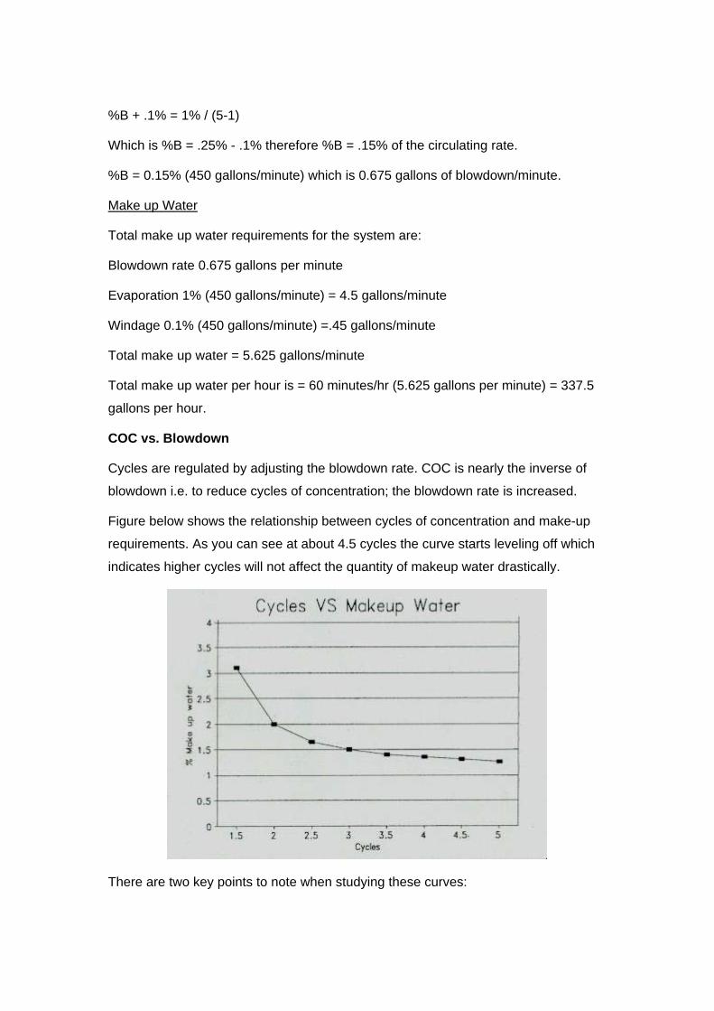
Figure below shows the relationship between cycles of concentration and make-up
requirements. As you can see at about 4.5 cycles the curve starts leveling off which
indicates higher cycles will not affect the quantity of makeup water drastically.
There are two key points to note when studying these curves:

1. As cycles of concentration increase, the resultant savings in makeup water
become less and less pronounced. Therefore, in each case very little
additional water is saved by operating above six cycles.
2. At lower evaporation rates (DT), the maximum makeup water savings occurs
at lower cycles.
Chemical savings are directly proportional to water savings. Table below illustrated
this point for a 10,000 gpm open recirculating system with a 10°DT.
Cycles Makeup (gpm) Chemical needed at 100 ppm (lbs)
1.5 300 240
2.0 200 120
4.0 133 40
5.0 125 30
10.0 111 13.3
Summarizing,
Operating system at maximum cycles of concentration gives following benefits:
1. Minimal water loss through blowdown;
2. Maximum recycling of water;
3. Minimum water consumption;
4. Minimal chemical requirement due to less water losses from the system;
5. Minimum water discharge to drain or effluent.
Chemical Dosing
The following list includes generic or family of chemicals which may be used to
condition cooling water stream. The specific name of the treatment product
containing the listed chemical depends on the manufacturer. Consult your chemical

supplier to formulate your dosage requirements and to establish procedures for safe
chemical storage and handling.
1. Polymers (Polyacrylate, etc) - Disperse sludge and distort crystal structure
of calcium deposits. Prevent fouling due to corrosion products. Commonly
used, cost effective for calcium scale at 5 to 15 mg/l.
2. Polymethacrylate - Less common for calcium scale at 5 to 15 mg/l.
3. Polymaleic - Very effective for calcium scales at 10 to 25 mg/l, higher cost.
4. Phosphonates - Phosphonates are excellent calcium scale inhibitors at
levels from 2 to 20 mg/l.
5. Sodium Phosphates (NaH2PO4, Na2HPO4, Na3PO4, NaPO3) - Precipitates
calcium as hydroxyapatite (Ca10(OH)2(PO4)6). Stream pH must be kept high
for this reaction to occur.
6. Sodium Aluminates (NaAl2O4) - Precipitates calcium and magnesium.
7. Chelants (EDTA, NTA) - Control scaling by forming heat-stable soluble
complexes with calcium and magnesium.
8. Coploymers - These products commonly incorporate two active groups, such
as a sulfonate and acrylate, to provide superior performance to a single group
compound at use levels at 5 to 20 mg/l, higher cost.
9. Terpolymers - Like the co-polymers, only incorporate three active groups to
give yet better performance under severe conditions at use levels of 5 to 20
mg/l, costly.
10. Polyphosphates - Fairly good calcium scale control under mild conditions.
Caution - Polyphosphates are of some value for scale control but must be
applied cautiously, because hydrolysis of the polyphosphate results in the
formation of orthophosphate ions. If this process is not properly controlled,
calcium phosphate deposits may result.
11. Tannins, starches, glucose, and lignin derivatives - Prevent feed line
deposits by coating scale crystals to produce sludge that will not readily
adhere to heat exchanger surfaces.
As a general rule, common chemical scale inhibitors such as polyacrylate and
phosphonate can be utilized if the Saturation Index (LSI) value of the cycled cooling

water does not exceed 2.0. Cycled cooling water SI values up to 3.5 can be obtained
by use of co- and terpolymers combined with surfactants. Multiple water treatment
firms have reported operation of cooling systems with newer treatment chemistries
scale free at cycled LSI values from 2.5 to 3.5 without pH adjustment.
Note that the scale and corrosion can result even when chemicals are applied at the
desired treatment levels if there is improper blowdown. When blowdown is excessive,
scale forming minerals and treatment chemicals are also removed making the water
more corrosive.and also increasing chemical costs. If blowdown is inadequate, scale
forming minerals build up in the system to the point that treatment chemicals cannot
overcome the tendency to form scale deposits.
It is highly recommended to use automatic conductivity blowdown controller to control
TDS wherever practical. It is better to control blowdown continuously or in small
frequent increments rather than infrequent long increments. This avoids wide swings
in the TDS level as well as chemical levels. Manual blowdown requires too much
effort to be effective and is not recommended.
Physical Water Treatment Methods
Hard water can be softened by two different methods. The first is the lime-soda
process which changes calcium and magnesium compounds from soluble to
insoluble forms and then removes these insolubles by sedimentation and filtration.
The second and most common is Zeolite or base-exchange process. This process
replaces soluble calcium and magnesium compounds with soluble sodium
compounds.
Zeolite Water softeners
Ion exchange is a chemical operation by which certain minerals that are ionized or
dissociated in solution are exchanged (and thus removed) for other ions that are
contained in a solid exchange medium, such as a zeolite sandbed. An example is the
exchange of calcium and magnesium, in solution as hardness in water, for sodium
contained in a sodium zeolite bed. The zeolites used in the process of ion exchange
are insoluble, granular materials. A zeolite may be classified as follows: glauconite
(or green sand), precipitated synthetic, organic (carbonaceus), synthetic resin, and
clay. Various zeolites are used, depending on the type of water treatment required.
Most zeolites possess the property cation, or base exchange, but anion exchangers
are also available and may be used when demineralization of water is required. In

the course of treating water, the capacity of the zeolite bed to exchange ions is
depleted. This depletion requires the bed to be regenerated by the use of some
chemical that contains the specific ion needed for the exchange. For instance, when
a sodium zeolite is used to soften water by exchanging the sodium ion for the
calcium and magnesium ions of hard water, the zeolite gradually becomes depleted
of the sodium ion. Thus, it will not take up the calcium and magnesium ions from the
water passing through the bed. The sodium ion is restored to the zeolite by uniformly
distributing a salt or brine solution on top of the bed and permitting it to pass evenly
down through the bed. The salt removes the calcium and magnesium taken up by the
bed as soluble chlorides and restores the zeolite to its original condition. Beds may
also be regenerated with acid, sodium carbonate, sodium hydroxide, or potassium
permanganate, depending on the type of zeolite being used.
The zeolite process is usually used for water which has low turbidity and does not
require filtration. Usually, it is NOT economically advantageous to install water
softeners unless the makeup water is more than 300 or 400 mg/L hardness.
Dealkalizer
Dealkalizer units operate the same as water softeners, but use different resin bed
materials and require strong caustic or acid regeneration. The makeup water is
passed through a treated resin bed where the contaminants in the water are
collected through a chemical exchange process. When the bed becomes saturated
with contaminants, the bed is backwashed, treated with a concentrated electrolyte,
rinsed, and placed back in service. For critical or continuous operations, treatment
units may be dual-column units that allow switching from a saturated column to a
regenerated standby column so that service is not interrupted for routine column
regeneration.
The ion exchange process is to remove calcium and magnesium ions by replacing
them with an equivalent amount of sodium ions. Unlike simple water softener, these
are mixed bed ion-exchange unit consisting of cation and anion exchanger. The
cation exchanger section removes metals, such as calcium and magnesium
(hardness), and the anion exchanger section controls alkalinity and may remove
bicarbonates (corrosion and embrittlement), sulfates (hard scale), chlorides
(foaming), and soluble silica (hard scale).
Magnetic devices

This method involves the exposure of incoming make up water under the intense
magnetic field. Magnetic field affects the suspended particles or the ions in solution
and prevents the deposition of a hardened deposit. The particles will then form a
mobile suspension or do not precipitate at all. Also, existing deposits of scale can be
converted into solution. Vendors of magnetic water treatment devices claim that
powerful magnetic fields can affect the structure of water molecules, thus eliminating
the need for chemical softening agents. Only the effective hardness is claimed to be
altered; no solutes (such as calcium or magnesium) are removed from the water by
the process.
Tests by independent sources have not yet corroborated the claims of vendors and
the readers are advised to research this further as a viable water treatment method.
Electronic De-Scaling technology
Electronic de-scaling technology makes use of induced oscillating electric fields using
time-varying magnetic fields generated in the solenoid wrapped around a water pipe.
Dissolved ions are then charged and collided with each other. Collisions between
positive and negative ions facilitate precipitation of the ions in the pipe-work.
Electronic de-scaling technology can be used to enhance chemical-based water
treatment program but caution: selection of chemicals used in corrosion inhibition
and micro-biological control shall be compatible with the technology.

SECTION - 4 CORROSION CONTROL
In open cooling water systems, oxygen cannot be economically removed because
these systems are constantly aerated. Therefore, corrosion inhibitors must be
utilized. Inhibitors are substances that do not necessarily alter the environment, but
do act as a barrier between the corrosive medium and the metal surface. These
materials, when added to the recirculating water, form a protective barrier on the
metal surface either by chemical reaction with the metal surface or by physical or
chemical adsorption on the metal surface. An actively corroding metal can be
rendered passive though the use of inhibitors that react in this manner.
The principle methods to prevent or minimizing corrosion include:
1. Selecting suitable materials of construction to resist corrosion
2. Adding protective film- forming chemical inhibitors that the water can
distribute to all wetted parts of the system.
3. Controlling scaling and micro-biological growth
4. Protect cathodically, using sacrificial metals
5. Apply protective coatings such as paints, metal plating, tar or plastics on
external surfaces
Treatment Methods
Most corrosion control strategies involve coating the metal with thin films to prevent
free oxygen and water from coming into close contact with the metal surface. This
breaks the reaction cell, and reduces the corrosion rates. Several major chemical
treatment methods can be used to minimize corrosion problems and to assure
efficient and reliable operation of cooling water systems.
Types of Corrosion Inhibitors
In general, there are four types of inhibitors: 1) anodic, 2) cathodic, 3) mixed and 4)
adsorption, commonly adopted in cooling water treatment. In addition passivation
technique is used for galvanized components. Working principles of common
corrosion inhibitors is described below.
Anodic inhibitor
Applying anodic inhibitor enables a protective oxide / inhibitor film to cover the anodic
corrosion points inside the cooling water circulation system. This method is effective

only if all points are filmed and isolated from corrosion initiator. Otherwise, severe
localized corrosion may occur at the points without effective protection by protective
film. Therefore, sufficient safety margin shall be applied and these shall generally be
applied at high dosage levels (hundreds of mg/l). Common anodic inhibitors are
chromates, nitrites, orthophosphates and silicates.
Cathodic inhibitor
Cathodic inhibitor is effective by the formation of protective inhibitor film at cathodic
corrosion sites so as to prevent oxygen reduction. It is more effective than anodic
inhibitor and lower dosage level is required. Therefore, it is commonly used in cooling
water treatment. Common cathodic inhibitors are bicarbonates, metal cations and
polyphosphates.
Mixed inhibitor
Mixed inhibitor composes of two or three types of inhibitor and majority of the
proprietary corrosion inhibitor formula falls into this category. Since chemicals with
different characteristics supplement their deficiency with each other, efficacy of the
mixed inhibitor increases. Hence, dosage concentration can be significantly reduced,
thus, lowering the operating cost and environmental impacts caused by chemicals.
Adsorption
Protective absorbed film is formed over the entire metal surface if adsorption inhibitor
is used. The film helps to protect electrochemical reactions between metal and
aqueous ions. Some of the organic compounds are suitable to act as adsorption
inhibitors.
Passivation
In order to prevent corrosion on galvanized steel cooling towers and associated
pipes, formation of a non-porous surface layer of zinc carbonate is one of the
effective methods. The formation of zinc carbonate layer is called passivation, which
is accomplished by controlling pH during initial operation of the cooling tower. Control
of the cooling water pH in the range of 7 to 8 for 45 to 60 days usually allows
passivation of surfaces. In addition to pH control, operation and moderate hardness
and alkalinity levels of 100 to 300ppm as CaCO3 will promote passivation.
Corrosion Control Chemicals
The following list notes some common inhibitors with pertinent comments.
1. Chromate - Excellent steel corrosion inhibitor, the standard against which all
others are compared, banned by the USEPA for environmental reasons.
2. Zinc - Good supplemental inhibitor at 0.5 to 2 mg/l level, some environmental
restrictions, can cause scale if improperly applied. Zinc enhances the effect of
some filming agents, but its use is sometimes limited by discharge regulations
that don’t allow the zinc to be discharged into the wastewater.
3. Molybdate - Non-toxic chromate replacement, often used as tracer, controls
pitting corrosion control at 4 to 8 mg/l, primary inhibitor for steel at 8 to 12
mg/l, higher levels, 35 to 250 mg/l in closed loop and severe environments,
very costly material.
4. Polysilicate - Excellent steel and aluminium inhibitor at 6 to 12 mg/l, not
commonly used due to formulation difficulty.
5. Azoles - Three specific azoles compounds, MBT, BZT, and TTZ, which are
excellent yellow metal inhibitor compounds at the 2 to 8 mg/l level.
6. Polydiol - A proprietary organic steel corrosion inhibitor at 2 to 4 mg/l, also a
dispersant.
7. Nitrate - Specific corrosion inhibitor for aluminum in closed loop treatments at
10 to 20 mg/l.
8. Ortho-phosphate - Good steel inhibitor at 4 to 12 mg/l, needs a minimum of
50 mg/l calcium present with a pH above 7.5 to be effective.
9. Polyphosphate - Good steel and yellow metal inhibitor at 4 to 12 mg/l, needs
a minimum of 50 mg/l calcium present with a pH above 7.5 to be effective.
10. Phosphonates - Includes AMP, HEDP, and PBCT, which are commonly
used as scale control compounds. Fair steel corrosion inhibitors when
operated with pH values above 7.5 and more than 50 mg/l calcium present.
11. Nitrite - Excellent steel corrosion inhibitor at 500 to 700 mg/l, commonly used
only in closed loops due to high level needed, attack by micro-organisms, and
reaction with oxygen.
Phosphates, particularly the polyphosphates, are most commonly used in cooling
water treatment. One advantage of using polyphosphates is that there is no yellow
residue such as produced by chromates. This highly undesirable residue is often

deposited on buildings, automobiles, and surrounding vegetation by the wind through
cooling towers or evaporative condensers, when the system is treated by chromates.
Also, polyphosphate treatment reduces corrosion products (sludge and rust) known
as tuberculation.
A factor limiting the use of polyphosphates in cooling water systems is the reversion
of polyphosphates to orthophosphates. Orthophosphates provide less protection than
polyphosphates, and orthophosphates react with the calcium content of the water
and precipitate calcium phosphate. This precipitation forms deposits on heat
exchanger surfaces. The reversion of polyphosphates is increased by long-time
retention and high water temperatures. Bleed-off must be adjusted on the condenser
water system to avoid exceeding the solubility of calcium phosphate. The ability to
prevent metal loss with polyphosphate treatment is inferior to the chromate
treatment. In addition, pitting is more extensive with polyphosphates.
For facilities where the cooling water system is constructed of several materials, a
blended inhibitor is required to obtain satisfactory corrosion protection. For example,
adding 2 mg/l of zinc to a phosphonate product at 10 mg/l reduced the corrosion rate
on mild steel from 2.2 mils/yr to 0.9 mils/yr. It is common to see programs using
mixtures such as molybdate-silicate-azole-polydiol, phosphonate-phosphate-azole,
and molybdate-phosphonate-polydiol-azole.
Seawater application
For seawater application, nitrites and phosphates at appropriate concentrations can
provide adequate protection. Organic inhibitors can also be used to provide
protection where nitrites cannot be used.
Cathodic Protection
Cathodic protection (CP) is a method used to protect metal structures, pipes and
equipments from corrosion. The cathodic protection can be obtained by connecting a
noble metal to a less noble. In practice steel is protected by supply of electrons from
less noble metal like Zinc, Aluminum and Magnesium alloys, often called sacrificial
anode materials. The anode is sacrificed and eventually is used up, but the steel is
protected.
Monitoring of Corrosion rate

Monitoring of corrosion rate is important to get feedback on the effectiveness of
treatment. An acceptable cooling water treatment program should be able to reduce
corrosion rates to the following average levels reported as mils/yr:
Rating Rate (Mils/yr)
Poor >5
Fair 3.5 – 5.0
Good 2.0 – 3.5
Excellent 0.0 – 2.0
The corrosion rate of mild steel for a 30-day exposure time in an open recirculating
cooling water system is generally rated to be acceptable below 2.0-3.5 mils per year
(mpy) and excellent if below 2.0 mpy. The corrosion rates for copper would be,
perhaps, 10% of those for mild steel.
Corrosion monitoring is done by various methods but most common method is by
“Test Coupons” Test coupons are generally installed in the following location
• At the outlet of hottest condenser/cooler;
• In cooling water return;
• In makeup water line.

SECTION - 5 CONTROL OF ORGANIC GROWTHS
The core of any microbiological treatment program is to feed an oxidizing biocide to
kill organisms before they can settle on condenser tubes, cooling tower fill and other
locations. Three general classes of chemicals are used in microbial control 1)
Oxidizing biocides, 2) Non-oxidizing biocides and 3) Bio-dispersants.
Oxidizing Biocide
Oxidizing biocides are powerful chemical oxidants, which kill virtually all micro-
organisms, including bacteria, algae, fungi and yeasts. Common oxidizers are
chlorine, chlorine dioxide, and bromine, ozone, and organo-chlorine slow release
compounds.
Chlorine
Chlorine is the most widely adopted biocide for large circulating water systems. It
provides a residual biocide in the treated water and can be readily checked. It is
cheap and readily available as a pure gas, as well as in the form of various liquid and
solid compounds. Its effectiveness increases when it is used with other non-oxidizing
biocides and biological dispersants.
Chlorine is a very strong oxidizing agent but must be carefully controlled and
monitored due to effluent quality control guidelines. The killing efficiency of chlorine
dramatically declines as the pH goes above 7.5. Because most cooling tower
scale/corrosion treatment programs operate at an alkaline pH, chlorine chemistry
might not be efficient. Chlorine demand is further affected by ammonia or amines in
the water, which react irreversibly to form the much less potent chloramines.
Chlorine when used in excess will damage wood and organic fill in cooling towers
and is corrosive to metals. Usually it is only used in systems large enough to justify
equipment for its controlled feed. Where chlorine is used on a continuous basis, the
concentration of free chlorine should be maintained at 0.3 to 0.5 mg/L to minimize the
attack on materials of construction. For cleaning purposes, shock feed of up to 50
mg/L can be used, provided this high chlorine content is held for no more than 8 h
and the system is thoroughly flushed and drained, to remove dead organic matter
and excess chlorine. Chlorine can be dosed in the form of sodium hypochlorite.

Caution - Chlorine and hypochlorites must be applied carefully, because excessive
chlorine will increase corrosion and may contribute to deterioration of cooling tower
wood and reduction of heat transfer efficiency.
Chlorine dioxide
Chlorine dioxide is another strong disinfecting agent that is effective in controlling
microbiological growth at high pH values. It is similar to free chlorine but having
certain advantages:
1. Chlorine dioxide does not react with ammonia this reduces the disinfectant
dose relative to chlorine.
2. Chlorine dioxide does not react with organics to the extent that chlorine or
bromine does; this reduces the cooling water demand for chlorine dioxide
relative to chlorine or bromine.
3. It is more effective than free chlorine at high pH values. Also, chlorine dioxide
is very effective against Legionella and its relatively long half life allows
chlorine residual remains in cooling tower water circuit for a relatively long
period.
Chlorine dioxide is an unstable chemical that must be generated on site. Chlorine
dioxide is produced by mixing the chlorinated water from a normal chlorinator and
sodium chlorite solution. The reaction takes place very quickly; however, the process
is more costly than simple chlorination. Chlorine dioxide is also generated
electrolytically from a variety of chemicals. For cooling tower applications, the
acid/sodium chlorite and acid/sodium hypochlorite/sodium chlorite generation method
are typically used.
Chlorine dioxide and some of the chemicals used to generate it are hazardous.
Alternatives to Chlorine
Due to safety concerns, Sodium hypochlorite (NaOCl) has replaced gaseous chlorine
at many facilities. Sodium hypochlorite is generally furnished as a solution that is
highly alkaline and therefore reasonably stable. Federal specifications call for
solutions having 5 and 10 percent available chlorine by weight. Shipping costs limit
its use to areas where it is available locally. It is so furnished as powder under
various names, such as Lobax and HTH-I5. The powder generally consists of
calcium hypochlorite and soda ash, which react in water to form sodium hypochlorite.

A popular alternative is bromine which has similar killing powers to chlorine, but
functions more effectively at alkaline pH. Another factor in favour of bromine is that it
does not react irreversibly with ammonia or amines. The primary disadvantages of
bromine vs. simple bleach are that an extra chemical is needed and feed systems
are a bit more complex.
Ozone
Ozone is a powerful biocide and virus deactivant that is capable of oxidizing many
organic and inorganic compounds. When reacting with another molecule, the ozone
molecule is destroyed, producing carbon dioxide, water, and a partially oxidized form
of the original reactant molecule. Any residual ozone will decompose and recombine
as oxygen, producing no toxic or carcinogenic by-products.
The potential benefits from ozone treatment are twofold:
1. Effective antimicrobial treatment without the use of expensive chemicals
2. Reduced blowdown since the ozone generation process precipitates out
dissolved solids
The effectiveness of ozone is about 100 to 300 times more than chorine and is not
significantly affected by pH. However, ozone is corrosive to some materials, and the
cooling system construction materials need to be resistant to ozone attack.
Application of ozone is not suitable under the following situations where excessive
organic material in the water or high operating temperature has a high depletion of
applied ozone:
1. High organic loading from air, water or industrial processes that would require
a high chemical oxygen demand (COD) since ozone oxidizes the organics
and insufficient residual may remain for the water treatment.
2. Water temperatures that exceed 110°F eliminate the effectiveness of ozone
treatment since high temperatures decrease ozone residence time.
3. Make up water is hard (>500 mg/L as CaCO3) or with sulphates greater than
100 ppm. Softening and / or pre-filtering of makeup water is recommended.
4. Since ozone has a short half life (usually less than 10 minutes), it readily
decomposes into oxygen after oxidization. It is not recommended in large
systems or systems that have long piping runs that would require long
residence times to get complete coverage.

Ozone exposure for workers is also a consideration. US- OSHA has established an
exposure limit of 0.1 ppm in the air over an 8-hr exposure period. Monitoring of ozone
concentration is required if towers are located at ground level, adjacent to personnel.
Hydrogen Peroxide
Hydrogen peroxide (H2O2) is a powerful oxidizer, with its power stronger than
chlorine and chlorine dioxide, but weaker than ozone. However, it can be catalyzed
into hydroxyl radicals (OH-), which is more powerful than ozone, for micro-organisms
control. Catalysts, such as iron, copper or other transition metals compounds can be
added to hydrogen peroxide to generate hydroxyl radicals for more rigorous
oxidation. This is the most powerful method to destroy micro-organisms and trace
organics in water.
Hydrogen peroxide decomposes into oxygen and water readily. It is a simple and
effective treatment technology when comparing with conventional water treatment
chemicals and does not cause any gaseous release or chemical residue problem.
However, hydrogen peroxide is totally soluble in water, which may cause safety
problems if high concentration >8% H2O2 by weight is used. Safety precaution in
storage, delivery, handling and disposal of hydrogen peroxide shall be considered,
which shall be complied with related guidelines.
Application of Oxidizing Biocide
The most effective use of oxidizing biocides is to maintain a constant level of residual
in the system. Oxidizing biocides are usually maintained at a continuous level in the
system. Dosage may be adjusted in response to regular testing but fully automatic
control of biocide level in using reliable and durable measuring systems is desirable
since overdosing can lead to increased corrosion and adversely affect the water
treatment performance. Shock dosing is also applicable, which can enhance the
effectiveness by faster killing action.
Since oxidizing biocide may sometimes be corrosive, corrosion inhibitors shall be
added and selected to ensure compatibility.
Non-Oxidizing Biocide
Non-oxidizing biocides are organic compounds, which kill micro-organism by
targeting specific element of the cell structure or its metabolic or reproductive
process. Non-oxidizing biocides are not consumed as fast as the oxidizing types and

remain in the system for a significant period of time until they pass out with the
blowdown. They often have the added advantage of breaking down into harmless,
nontoxic chemicals after accomplishing their bacteria-killing purpose. They are
effective where chlorine may not be adequate.
However, the non-oxidizing biocides are more costly and normally justified only in
small systems, as a supplement to an oxidizing biocide in a large system, or when a
particular problem exists in a large system and an alternative to the use of chlorine is
required.
• Non-oxidizing biocides usually are organic compounds such as ammonium
salts, Isothiazolinones, organo-metallics and organo-sulfur compounds.
• Quaternary ammonium salts or diamines are sometimes found to be toxic, but
the low concentration application allows them to maintain in an acceptable
limit for discharge.
• Isothiazolinones are biodegradable, which cause little adverse impacts to the
environment.
• Glutaraldehyde is an effective and rapid-acting biocide and its reactivity
prevents it from persisting to harm the environment.
• Non-oxidizing biocides such as organo-metallics, chlorophenols, organo-
sulfur compounds and cationic biocides have not been adopted for use in
large circulating water systems because of economics, degree of
effectiveness, adverse side effects, or a combination of these reasons.
Advantages to using non-oxidizing biocides:
1. They are well suited to applications that are highly concentrated or fouled.
2. Contaminants such as ammonia, organic material, or nitrites cause a chlorine
demand but do not affect a properly applied non-oxidizing biocide program.
3. They are active at low levels and are environmentally degradable, providing
minimal discharge problems.
4. They will not attack organic scale inhibitors and are less corrosive than
chlorine at normal dosages.

Disadvantages to using non-oxidizing biocides:
1. The cost is considerably higher.
2. They are pH sensitive.
3. Some are specific to certain microbial organisms.
4. Some are not effective against algae.
5. In order to ensure the effectiveness of non-oxidizing biocides, monitoring of
chemical concentration in cooling tower systems is required.
Typically, except in air conditioning cooling systems, non-oxidizing biocides are used
only as a supplement to chlorine. If, during operation, it is determined that a non-
oxidizing biocide is required because of severe fouling problems, the chemical
supplier should be consulted on the method of feed. Normally, the supplier will lease
the storage and feed equipment for a minimal charge.
BIO - DISPERSANTS
Bio-dispersants do not kill organisms; they loosen microbial deposits, which can then
be flushed away. They also expose new layers of microbial slime or algae to the
attack of biocides. Bio-dispersants are an effective preventive measure because they
make it difficult for micro-organisms to attach to equipment and / or pipe work
surfaces to form deposits. Bio-dispersants can greatly enhance performance of
biocides particularly oxidizing biocides. Possible bio-disperants include Acrylates,
Ligonsulphonates, Methacrylates and Polycarboxylic acids, etc.
Biocide Dosage Rates
Biocide treatment is designed to either periodically shock the microorganisms with a
relatively heavy dose of chemical, or maintain a continuous biocide residual in the
circulating water. Below the lower threshold value of the biocide, the microorganisms
will begin to multiply again. The recommended practices are:
1. Continuous chlorine residual systems typically maintain a residual of 0.5–1
mg/l as Cl2.
2. Intermittent sodium hypochlorite feed systems typically dose at about 3 mg/l
as Cl2 for
1–2 hours per day to the circulating water flow. Shock chlorination is typically
done 2–4 times per day, each with duration of 20–30 minutes.

3. Continuous bromine residual systems typically maintain a residual of 0.5–1
mg/l as Br.
4. Continuous chlorine dioxide residual systems typically maintain a residual of
0.2–0.5 mg/l as ClO2.
5. Intermittent chlorine dioxide feed systems typically dose at about 1.5 mg/l as
ClO2 for
1–2 hours per day to the circulating water flow. Shock chlorine dioxide feed is
typically done 2–4 times per day, with duration of 20–30 minutes.
6. Non-oxidizing biocide are generally slug-fed (such as once a week) at high
concentrations. The concentration is specific to the biocide, but is typically in
the 5–30 mg/l range as product.
To stay within the chlorine discharge limits, feed rates of 3ppm chlorine or less are
required, depending on the circulating water system.
Other Supplementary Methods
UV Treatment
UV disinfection, with secondary dosing using a suitable biocide, is one of the most
cost-effective and efficient methods of reducing biofilms in cooling water. When used
in conjunction with a secondary chemical biocide, UV works instantaneously against
all water-borne microorganisms including those resistant to chlorine.
The treatment systems are very compact and can usually be easily retrofitted to
existing water treatment systems. In addition, secondary dosing does not require the
complex monitoring equipment necessary if biocides are used as a primary
disinfectant. All these factors add up to a simple, effective treatment process that
saves the operator time and money while providing reliable protection against the
spread of dangerous diseases.
UV is the part of the electromagnetic spectrum between visible light and X-rays. The
specific portion of the UV spectrum between 185-400nm (also known as UV-C) has a
strong germicidal effect, with peak effectiveness at 265nm. At these wavelengths UV
kills microorganisms by penetrating their cell membranes and damaging the DNA,
making them unable to reproduce and effectively killing them.
A typical UV disinfection system consists of a UV lamp housed in a protective quartz
sleeve which is mounted within a cylindrical stainless steel chamber. The water to be

treated enters at one end and passes along the entire length of the chamber before
exiting at the other end.
Copper and Silver Ionization
Ionization indicates the electrolytic generation of copper and silver ions in cooling
tower water. If properly managed, copper and silver ion concentrations at 20 to 30
µg/L and 10 to 15 µg/L, respectively, can be effective to kill bacteria in the systems.
The ions assist in the control of bacterial populations in the presence of a free
chlorine residual of at least 0.2 mg/kg.
It should be noted that in hard water systems, silver ion concentrations is difficult to
maintain due to build-up of scale on the electrodes, and the high concentration of
dissolved solids precipitating the silver ions out of solution. For both hard and soft
water, the ionization process is pH sensitive and it is difficult to maintain silver ion
concentrations above pH 7.6. It is not recommended to adopt ionization in systems
having steel or aluminium heat exchanger since deposition of the copper ion and
subsequent galvanic corrosion is significant.

SECTION - 6 TURBIDITY CONTROL
Another problem area besides organic growth is turbid water, so let’s now study
turbidity.
Turbidity in water is caused by suspended matter in a finely divided state. Clay, silt,
organic matter, microscopic organisms, and similar materials are contributing causes
of turbidity. While the terms “turbidity” and “suspended matter” are related, they are
not synonymous. Suspended matter is the amount of material in water that can be
removed by filtration. Turbidity is a measurement of the optical obstruction of light
that is passed through a water sample.
Turbid makeup water to cooling systems may cause plugging and overheating where
solids settle out on heat exchanger surfaces. Corrosive action is increased because
the deposits hinder the penetration of corrosion inhibitors.
Turbidity Treatment
Filtration is the most common method for removing suspended matter such as mud,
silt and microbial matter from water by collecting the solids on a porous medium.
Removing suspended matter helps the overall water management program's
success by eliminating deposit-causing substances, as well as chemical treatment
products to work more effectively.
There are two methods of filtration:
1. Full-flow filtration: Full flow filtration continuously strains the entire system
flow. For example, in a 100-ton system, the flow rate would be roughly 300
GPM. A filter would be selected to accommodate the entire 300 gal/min flow
rate. In this case, the filter typically is installed after the cooling tower on the
discharge side of the pump. While this is the preferred method of filtration, for
higher flow systems, it may be cost prohibitive.
2. Side-stream filtration: Here, a portion of the water is diverted through a filter
for removal of dirt and suspended solids. These systems draw water from the
sump, filter out sediment and return the filtered water to the tower, enabling
the system to operate more efficiently with less water and chemicals. Side-
stream filtration is particularly cost effective for high flow systems.
Properly sized side-stream filtration system is critical to obtain satisfactory
filter performance. A common rule-of-thumb suggests a filter size capable of

handling water at a rate equivalent to 3 to 5% of the total circulation flow rate.
For example, if the total flows of a system is 1,200 gpm (a 400-ton system); a
60 gal/min side-stream system is specified. A more accurate approach is to
calculate the system's total water volume and filter it once per hour. Thus, it is
necessary to determine the total system water volume contained in the tower
basin and wet deck, condenser water piping, condenser(s), etc., and divide
that volume, in gallons, by 60min to establish the required filter flow rate, in
gpm.
Both in-line filtration and side-stream filtration processes help in reducing suspended
solids to an acceptable level. These filters not only reduce the potential for settling of
particulates in condenser tubes and low-flow locations, but also remove microbes
and particulates that would otherwise consume some of the polymers utilized for
scale control.
Filtration Equipment
A number of mechanical filtration devices commonly used in cooling tower systems
are:
1. Strainers – A strainer is a closed vessel with a cleanable screen to remove
and retain foreign particles down to 25µm diameter inside cooling water. It
shall only be used as pre-filtration to remove large particles in the system.
2. Cartridge filters – Cartridge filters utilize a pleated, porous medium as a
filtering medium and can be cleanable and reusable or disposable. These
have a filtration range of 0.1 micron to 100 microns. Cartridge filters are
preferable for systems with contaminations less than 100 ppm that means
with contamination levels less than 0.01% by weight. For concentrations that
are bigger than 100ppm then a bag filter or some other method should be
used.
3. Sand filters (Permanent media filters) – Sand filters are used for water
purification. The degree of suspended solids removal in sand filters depends
on the combinations and grades of the medium being used in the vessel.
Typical sand filter can remove suspended contaminants down to 10µm.
Specialized fine sand media filters are designed to remove suspended
particles down to less than 1µm. Multimedia vessels with each layer
containing medium of different size may also be used for low suspended

solids application. When the vessel has retained enough suspended solids to
develop a substantial pressure drop, the unit must be backwashed either
manually or automatically by reversing the direction of flow.
4. Centrifugal-gravity separators – Cooling water is drawn through tangential
slots and accelerated into the separation chamber. Centrifugal action tosses
the particles heavier than the liquid to the perimeter of the separation
chamber. Efficiency of centrifugal-gravity separator depends on the
gravitational mass of suspended solids; performance data indicate that
separator efficiency is about 40% for particles in the range of 20µm to 40µm.
5. Bag type filters – Bag filters are composed of a bag of mesh or felt
supported by a removable perforated metal basket, placed in a closed
housing with an inlet and outlet. Filter bags can be made of many materials
(cotton, nylon, polypropylene and polyester) with a range of ratings from
0.01mm to 0.85mm. Mesh bag are generally coarser, but are reusable.
However, periodic replacement of filters is required to ensure the efficiency of
filters.
Coagulants, flocculators, and sedimentation basins are also used but are more
common to large water treatment facilities.
Selection Recommendations
The type and density of the suspended solids is a key for selecting an effective filter.
Sand, corrosion products and scales are very dense whereas vegetation,
microbiological biomass and oily/greasy products are very light and float readily in
the water. Bacteria are very small -- actually minute -- while corrosion products such
as chips are very large. Selection of the filter and its media must identify these
considerations. As a rule of thumb, keep the following tips in mind:
1. If mainly sand and other dense particulates are present, a cyclone separator
is ideal.
2. If the suspended solids are lightweight, then a sand filter or cartridge filter will
work well.
3. For a cooling tower system operating 24 hours per day, use a side-stream
filtration system that filters the entire volume of the system four to five times
per day. As an alternative, 3 percent to 5 percent of the recirculation rate is

used. Using this calculation method, if the recirculation rate is 5,000 gal/min,
filter 150 to 250 gal/min.
4. To conserve water and treatment chemicals, backwash filters with makeup
water, not system water.
5. If oil and/or grease are present with suspended solids, use an oil water
separator and then filter the separated water to remove suspended solids.
6. Dispersants often used for cooling water treatment break up suspended
solids so fine that sand filters may not work very well. Media should be much
finer or precoat used.
7. Filter media may harbour microbiological organisms and should be
disinfected periodically.

SECTION - 7 WATER TREATMENT SYSTEM CONTROLS & MONITORING
Chemical Dosing
Water treatment chemicals shall be added to turbulent zones of cooling tower
water system to achieve rapid mixing and well distribution of chemicals. Also,
separate dosing point shall be used to ensure dilution of one potentially reactive
chemical prior to adding the second chemical. The dosage concentration of
chemicals, including inhibitors and biocides, shall be calculated based on the total
quantity of water, make up water quality and bleed-off rate.
The purpose of most chemical treatment control programmes (other then certain
biocides) is to maintain a constant concentration in the recirculating water at
all times. In order to maintain a stable chemical concentration in cooling water,
a number of application methods can be adopted, including:
a. Shot / slug dosing;
b. Continuous / intermittent dosing;
c. Proportional dosing related to bleed-off volume;
d. Proportional dosing related to make up water volume;
e. Dosing controlled by sensor.
Shot / slug dosing
Chemicals are added to the system manually on a routine basis. Shot / slug dosing
is the most economic and effective application method, which may be adopted in
small-scale cooling tower installation. However, it is not recommended because
chemical concentration cannot be controlled accurately and large fluctuations in
chemical levels are always found.
Continuous / intermittent dosing
Continuous / intermittent dosing makes use of mechanical devices, such as timer and
pump for chemical dosing. It is the simplest type of automatic dosing system. Since
chemical dosing frequency and amount is regulated by the pre-set value,
fluctuation of chemical concentration inside cooling tower water is always found.
Proportional dosing related to bleed-off volume

System bleed-off can be controlled by simple timer, conductivity sensor or make up
water flow. Signal from the device can also be used to initiate chemical dosing. When
the conductivity of the system water reaches a pre-determined value, a timer can be
actuated which allows a dosage pump to run for a period to add the requisite
amount of chemicals, in relation to the make up water entered the system.
A delay timer shall be installed to prevent wasteful chemical addition during
bleed-off.
Proportional dosing related to make up water volume
Proportional dosing maintains a nearly constant chemical level by dosing in
proportion to a varying make up water rate. The treatment requirement is based on
make up water quantity and injection rate varies as the water make up changes.
Impulse water meter installed in make-up line shall be used to activate a chemical
dosing pump. Proportional dosing can be applied to all cooling tower systems
continuously. Such dosing is particular benefit to systems which operate under
conditions with great varieties.
Dosing controlled by sensor
Dosing controlled by sensor is ideal for controlling chemical concentration in a
system. Correct amount of chemical is continuously presented to the system once
the dosing rate and frequency are gauged by operational parameters. Therefore,
concentration of chemicals inside cooling tower water can be maintained within a
designated range. pH sensor, redox probes and oxidation reduction potential (ORP)
probes are commonly used to control dosing of acids and oxidizing biocides,
respectively.
Bleed-off Control
For an accurate bleed-off control system, automatic control by conductivity sensor is
recommended to regulate the amount of bleed-off required. Conductivity is a
measure of total ionic concentration in water, hence, concentration of total
dissolved solids (TDS). Bleed-off control is a critical part to ensure scale prevention
in water-cooled air conditioning systems.
Bleed-off rate is related to the cycle of concentration, which shall be determined by
water treatment methods being adopted. If a comprehensive water treatment
programme, including both chemical and physical methods, is implemented to

control scale, corrosion and micro-biological growth effectively, bleed-off rate can be
significantly reduced.
There are a number of methods to control bleed-off, including:
a. Manual control: a bleed valve is opened in response to test measurements;
b. Timer / intermittent control: a simple interval timer is set to open and close the
bleed valve intermittently;
c. Continuous bleed: an orifice plate or pre-set valve is set to release
water continuously;
d. Proportional control: an impulse water meter on the make up line actuates the
bleed valve
e. Conductivity control: the cooling water conductivity is continuously monitored
and the bleed-off valve is opened at a pre-set conductivity.
A number of points shall be considered for a bleed-off system.
a. To ensure the bleed assembly can be isolated from the system
for maintenance purposes;
b. To ensure the head of the conductivity sensing probe is positioned in the
main water flow, but not where air pockets can develop;
c. To place the conductivity sensing probe upstream of the bleed-off
system solenoid valve;
d. To clean the conductivity sensing probe regularly;
e. To regulate valve in the bleed line so that the flow cannot exceed the make
up water to the system;
f. To provide an alarm signal when solenoid valve and flow switch signals in the
bleed-off line do not correspond.
Central Monitoring and Control

Water treatment monitoring can be controlled through Building Management System
(BMS). It co-ordinates the entire system operation and water treatment
programme. This control strategy may have the following advantages:
a. Accurate dosing control is assured which optimizes chemical usages;
b. Bleed-off and chemical dosage would not occur at the same time so
that wastage of chemicals on drainage can be avoided;
c. Adjustment of water treatment programme in accordance with cooling tower
system operation can be performed in the central control system;
d. Minimal chemical handling is required to reduce the risks of the
operators’ health and safe;
e. Water consumption, energy consumption, chemicals consumption are
recorded accurately; and
f. Any malfunction of water treatment equipment can be reported immediately.
Monitoring Devices
Sensors are generally used as monitoring devices in water-cooled air conditioning
system. Comparison between the measuring results and the set points for specific
parameter are useful to determine the control action required for normal operation.
Different type of sensors to be selected is relied on the control strategy. Common
types of sensors are described as follows.
Flow meter
Chemical feeding requirements are proportional to the make up water flow. Many
chemical feeding systems are designed according this basis, which is the simplest
automatic dosing method. Flow meters including orifices venturi, flow tubes and
turbine meters can be used to suit the design.
Level sensor
Make up water supply to cooling tower sump depends on water level of cooling tower
basin. Hence, chemical dosing can be controlled by monitoring of the water level.
However, this dosing method is not accurate and cannot control the
concentration of chemicals contained in the cooling system water precisely.
Conductivity sensor
Electrical conductivity of water relies on total ionic concentration of water, which
indicates the concentration of total dissolved solids (TDS) in water. Both corrosion
rate and scale formation potential for any specific systems are normally proportional
to the conductivity of water. Conductivity sensor is frequently employed as chemical
detection device. The sensor is usually used for bleed-off system for the control of
cycles of concentration.
pH sensor
Carbon steel corrosion rate decreases with an increase in pH value, and the scale
potential for most scale forming compounds increases with pH value. Also, water
treatment chemicals work in specific range of pH value. Hence, pH value
measurement is often the basic principle for acid dosing to maintain effective water
treatment programme.
ORP probe
ORP probe is used as real time monitoring and recording of oxidation
reduction potential, which can be utilized to monitor chlorine residuals in
cooling tower systems. It measures the inorganic and organic particles remains in
cooling water so as to facilitate chemical dosing. ORP probe shall be used
together with pH sensor since ORP values vary with pH value.
Chlorine residuals sensor
Chlorine is commonly employed biocide for water-cooled air conditioning system.
Continuously measuring chlorine residual analyzer is commercially available to
measure either free or total chlorine residual.
Turbidity sensor
Turbidity measurement provides an indication of the amount of suspended matter in
cooling water, which is useful in determining deposit potential. Therefore, it can be
used for bleed-off control.
Corrosion rate sensors
Corrosion rate sensors are available in the market to provide continuous,
instantaneous measurement of corrosion rates for any alloy. These sensors are

normally based on linear polarization resistance between a pair of electrodes.
Corrosion coupon test method can also be used to determine corrosion rate.
Sensors for specific ions and Compounds
Sensors are commercially available to measure ion concentrations in water. Many
analyzers are also available to measure either compounds or classes of compounds
or classes of compounds dissolve in water.
The selection of proper location of sensors in the water-cooled air conditioning
system is very important. Sensors measuring treatment chemicals shall be located at
a point after the treatment is well mixed. Corrosion rate increases with increasing
temperature. Therefore, corrosion monitoring device should be installed at the outlet
of the heat exchanger where water with the highest temperature is passing through.
Requirement of measurement and reliability of sensor shall also be considered in
selecting an appropriate device.
Control Devices
In order to achieve maximum effectiveness of water treatment programme, chemicals
must be dosed into the system in an appropriate concentration
periodically. Since handling of chemicals may be dangerous, it is always
recommended to perform chemical dosing by means of automatic monitoring and
control strategy. Chemical injection can be facilitated by different control devices.
Timer
It is a simple device allowing operator to set the operation of chemical dosing valve,
hence, chemical dosing frequency, in a fix interval. Also, circulation of water during
system intermittent down time can be achieved by using timer control.
Dosing pump
Dosing pump can be operated manually or automatically. For automatic control,
dosing pump activates upon receiving signal from timer or sensors. It runs for a
certain period to inject chemicals into the cooling tower water circuit.
Motorized valve
Motorized valve is an essential component for automatic controlled chemical dosing
and bleed-off. It will switch to open / close position upon receipt of signal from
monitoring devices, such as water meter and conductivity sensor.

Occupational Safety and Health
Water treatment may involve application of relatively aggressive and toxic chemicals,
which is the major concern. All personnel involved must be fully conversant with the
safe handling of the products.
a. Material safety data sheet (MSDS) and relevant recognized data sheet for
chemicals used in water treatment process shall be provided by water
treatment services providers and included in the operation and
maintenance manual. MSDS and relevant warning / safety label shall be
provided on the surface of water treatment chemical bucket. The MSDS and
labels shall be properly protected against water and chemical damage.
b. Eye wash bottles or washing basin with fresh water tap shall be provided
adjacent to water treatment chemicals tanks or any appropriate location for
emergency use. Water treatment chemical shall be stored at an
appropriate location to facilitate chemical handling.
c. Mechanical / natural ventilation shall be provided to the room entirely /
partially used for water treatment chemical storage.
d. Electrical fittings and luminaries serving water treatment chemical storage
area shall be weather-proof and corrosion resistant type.
e. Warning signs shall be erected to alert for operation and maintenance
personnel of the potential hazard caused by cooling tower.
f. Warning signs shall also be erected to restrict the unauthorized access to
chemical storage areas and cooling towers.
g. Workers exposed to hazardous substances and engaged in processes of
cleaning and disinfection and water treatment shall undergo regular health
surveillance with a medical practitioner. In case any worker develops
respiratory, cutaneous and other symptoms when exposed to
hazardous chemicals, immediate medical attention shall be sought.
Course Summary
In today's world of expensive energy and replacement costs, it is more vital than
ever, for heat exchange equipment to be kept free of insulating deposits. The cooling
duty and power requirements of refrigeration equipment depend primarily on the
evaporating and condensing temperatures. The condenser in particular due to warm

water and in an open loop is susceptible to scale deposits that shall raise the
condensing temperature of the system. Higher the condensing temperature, higher
shall be the power drawn by the compressor and lower shall be the performance.
The four principal reasons for water treatment in HVAC systems is to (a) to limit
corrosion, (b) to prevent the build-up of scale and sediment, and (c) to reduce the
amount of bacteria, including Legionella, and other microorganisms and (d) to affect
energy conservation.
The energy losses can be controlled by implementing a proper water treatment
program. During normal operation, it may not be possible for the operators to
understand the severity and magnitude of the problem. A routine O & M practices
shall provide a clue of higher current drawn by the compressor and a drop in cooling
range (differential of cooling water inlet and outlet temperature) across the
condenser.
The common chemical inhibitors compounds are: Chromates, Poly-Phosphates,
Zinc, Nitrates, Silicates and Sodium Meta Phosphate (SHMP).
Select your chemical treatment vendor with care. A simplest approach for HVAC
system is to perform vendor evaluation on "cost to treat 1000 gallons makeup water"
and highest "recommended system water cycle of concentration."