course structure iv b.tech eee (r13) iv year i … structure iv b.tech eee (r13) iv year – i...
TRANSCRIPT
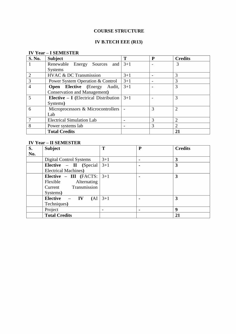
COURSE STRUCTURE
IV B.TECH EEE (R13)
IV Year – I SEMESTER
S. No. Subject T P Credits
1 Renewable Energy Sources and
Systems
3+1 - 3
2 HVAC & DC Transmission 3+1 - 3
3 Power System Operation & Control 3+1 - 3
4 Open Elective (Energy Audit,
Conservation and Management)
3+1 - 3
5 Elective – I (Electrical Distribution
Systems)
3+1 - 3
6 Microprocessors & Microcontrollers
Lab
- 3 2
7 Electrical Simulation Lab - 3 2
8 Power systems lab - 3 2
Total Credits 21
IV Year – II SEMESTER
S.
No.
Subject T P Credits
Digital Control Systems 3+1 - 3
Elective – II (Special
Electrical Machines)
3+1 - 3
Elective – III (FACTS:
Flexible Alternating
Current Transmission
Systems)
3+1 - 3
Elective – IV (AI
Techniques)
3+1 - 3
Project - - 9
Total Credits 21

IV Year – I SEMESTER
RENEWABLE ENERGY SOURCES AND SYSTEMS
Preamble:
This course gives a flavor of renewable sources and systems to the students. It introduces
solar energy its radiation, collection, storage and its applications. This covers generation,
design, efficiency and characteristics of various renewable energy sources including solar,
wind, hydro, biomass, fuel cells and geothermal systems.
Learning Objectives:
To study the solar radiation data, extra terrestrial radiation, radiation on earth’s
surface.
To study solar thermal collections.
To study solar photo voltaic systems.
To study maximum power point techniques in solar pv and wind.
To study wind energy conversion systems, Betz coefficient, tip speed ratio.
To study basic principle and working of hydro, tidal, biomass, fuel cell and
geothermal systems.
UNIT–I:
Fundamentals of Energy Systems
Energy conservation principle – Energy scenario (world and India) – Solar radiation: Outside
earth’s atmosphere – Earth surface – Analysis of solar radiation data – Geometry – Radiation
on tilted surfaces – Numerical problems.
UNIT–II:
Solar Thermal Systems
Liquid flat plate collections: Performance analysis – Transmissivity – Absorptivity product
collector efficiency factor – Collector heat removal factor – Numerical problems.
Introduction to solar air heaters – Concentrating collectors and solar pond.
UNIT–III:
Solar Photovoltaic Systems
Balance of systems – IV characteristics – System design: storage sizing – PV system sizing –
Maximum power point techniques: Perturb and observe (P&O) technique – Hill climbing
technique.
UNIT–IV:
Wind Energy
Wind patterns – Types of turbines – Kinetic energy of wind – Betz coefficient – Tip–speed
ratio – Efficiency – Power output of wind turbine – Selection of generator(synchronous,
induction) – Maximum power point tracking.
UNIT–V:
Hydro and Tidal power systems
Basic working principle – Classification of hydro systems: Large, small, micro –
measurement of head and flow – Energy equation – Types of turbines – Numerical problems.
Tidal power – Basics – Kinetic energy equation – Numerical problems – Wave power –
Basics – Kinetic energy equation.
UNIT–VI:
Biomass, fuel cells and geothermal systems
Biomass Energy: Fuel classification – Pyrolysis – Direct combustion of heat – Different
digesters and sizing.
Fuel cell: Classification – Efficiency – VI characteristics. Geothermal: Classification – Dry
rock and acquifer – Energy analysis.
Learning Outcomes:
Student should be able to
Analyze solar radiation data, extraterrestrial radiation, radiation on earth’s surface.
Design solar thermal collections.
Design solar photo voltaic systems.
Develop maximum power point techniques in solar PV and wind.
Explain wind energy conversion systems, Betz coefficient, tip speed ratio.
Explain basic principle and working of hydro, tidal, biomass, fuel cell and geothermal
systems.
Text Books:
1. Solar Energy: Principles of Thermal Collection and Storage, S. P. Sukhatme and J. K.
Nayak, TMH, New Delhi, 3rd Edition.
2. Renewable Energy Resources, John Twidell and Tony Weir, Taylor and Francis -second
edition, 2013.
3. Energy Science: Principles, Technologies and Impacts, John Andrews and Nick Jelly,
Oxford.
Reference Books:
1. Renewable Energy- Edited by Godfrey Boyle-oxford university, press, 3rd edition, 2013.
2. Handbook of renewable technology Ahmed and Zobaa, Ramesh C Bansal, World
scientific, Singapore.
3. Renewable Energy Technologies /Ramesh & Kumar /Narosa.
4. Renewable energy technologies – A practical guide for beginners – Chetong Singh
Solanki, PHI.
5. Non conventional energy source –B.H. Khan- TMH-2nd edition.

HVAC & DC TRANSMISSION
Preamble:
With the increasing power generation in the country and long distance power transmission, it
is necessary that power should be transmitted at extra and ultra high voltage. The topics dealt
in this subject relate to phenomena associated with transmission line at higher voltages,
equipments generating high voltage and power control strategy.
Learning Objectives:
To understand the phenomena associated with transmission line, operating at extra
high voltages. The unit gives detail analysis of several phenomena viz. electrostatic
field, charges, voltage gradient and conductor configuration.
The objective is to discuss phenomena of corona, losses, audible noise, radio
interference and measurement of these quantities.
To understand the phenomena of HVDC, HVDC equipment comparison with AC and
the latest state of art in HVDC transmission.
To understand method of conversion of AC to DC, performance of various level of
pulse conversion and control characteristics of conversion. It also provides knowledge
of effect of source inductance as well as method of power control.
To understand the requirements of reactive power control and filtering technique in
HVDC system.
To understand the harmonics in AC side of power line in a HVDC system and design
of filters for various levels of pulse conversion.
UNIT – I:
Introduction of EHV AC transmission
Necessity of EHV AC transmission – Advantages and problems – Power handling capacity
and line losses – Mechanical considerations – Resistance of conductors –Electrostatics –
Field of sphere gap – Field of line charges and properties – Charge ~ potential relations for
multi–conductors – Surface voltage gradient on conductors – Bundle spacing and bundle
radius – Examples – Distribution of voltage gradient on sub conductors of bundle –
Examples.
UNIT – II:
Corona effects
Power loss and audible noise (AN) – Corona loss formulae – Charge voltage diagram –
Generation – Characteristics – Limits and measurements of AN – Relation between 1–phase
and 3–phase AN levels – Examples – Radio interference (RI) – Corona pulses generation –
Properties and limits – Frequency spectrum – Modes of propagation – Excitation function –
Measurement of RI, RIV and excitation functions – Examples.
UNIT – III:
Basic Concepts of DC Transmission
Economics & Terminal equipment of HVDC transmission systems: Types of HVDC Links –
Apparatus required for HVDC Systems – Comparison of AC &DC transmission –
Application of DC Transmission System – Planning & Modern trends in DC transmission.
UNIT – IV:
Analysis of HVDC Converters and System Control
Choice of Converter configuration – Analysis of Graetz – Characteristics of 6 Pulse & 12
Pulse converters – Cases of two 3 phase converters in star – Star mode and their performance
– Principal of DC Link Control – Converters Control Characteristics – Firing angle control –
Current and extinction angle control – Effect of source inductance on the system – Starting
and stopping of DC link – Power Control.
UNIT–V:
Reactive Power Control in HVDC
Reactive Power Requirements in steady state – Conventional control strategies –Alternate
control strategies sources of reactive power – AC Filters – Shunt capacitors – Synchronous
condensers.
UNIT – VI:
Harmonics and Filters
Generation of Harmonics – Characteristics harmonics – Calculation of AC Harmonics –
Non–Characteristics harmonics – Adverse effects of harmonics – Calculation of voltage &
current harmonics – Effect of Pulse number on harmonics. Types of AC filters, Design of
Single tuned filters – Design of High pass filters.
Learning Outcomes:
To be able to acquaint with HV transmission system with regard to power handling
capacity, losses, conductor resistance and electrostatic field associate with HV.
Further knowledge is gained in area of bundle conductor system to improve electrical
and mechanical performance.
To develop ability for determining corona, radio interference, audible noise
generation and frequency spectrum for single and three phase transmission lines.
To be able to acquire knowledge in transmission of HVDC power with regard to
terminal equipments, type of HVDC connectivity and planning of HVDC system.
To be able to develop knowledge with regard to choice of pulse conversion, control
characteristic, firing angle control and effect of source impedance.
To develop knowledge of reactive power requirements of conventional control, filters
and reactive power compensation in AC. side of HVDC system.
Able to calculate voltage and current harmonics, and design of filters for six and
twelve pulse conversion.
Text Books:
1. HVDC Power Transmission Systems: Technology and system Interactions – by
K.R.Padiyar, New Age International (P) Limited, and Publishers.
2. Direct Current Transmission – by E.W.Kimbark, John Wiley & Sons.
3. EHVAC Transmission Engineering by R. D. Begamudre, New Age International (P) Ltd.
Reference Books:
1. EHVAC and HVDC Transmission Engineering and Practice – S.Rao.
2. Power Transmission by Direct Current – by E.Uhlmann, B.S.Publications
3. HVDC Transmission – J. Arrillaga.

POWER SYSTEM OPERATION AND CONTROL
Preamble:
This subject deals with Economic operation of Power Systems, Hydrothermal scheduling and
modeling of turbines, generators and automatic controllers. It emphasizes on single area and
two area load frequency control and reactive power control.
Learning Objectives:
To understand optimal dispatch of generation with and without losses.
To study the optimal scheduling of hydro thermal systems.
To study the optimal unit commitment problem.
To study the load frequency control for single area system
To study the PID controllers for single area system and two area system.
To understand the reactive power control and compensation of transmission lines.
UNIT–I:
Economic Operation of Power Systems
Optimal operation of Generators in Thermal power stations, – Heat rate curve – Cost Curve –
Incremental fuel and Production costs – Input–output characteristics – Optimum generation
allocation with line losses neglected – Optimum generation allocation including the effect of
transmission line losses – Loss Coefficients – General transmission line loss formula.
UNIT–II:
Hydrothermal Scheduling
Optimal scheduling of Hydrothermal System: Hydroelectric power plant models –
Scheduling problems – Short term Hydrothermal scheduling problem.
UNIT–III:
Unit Commitment
Optimal unit commitment problem – Need for unit commitment – Constraints in unit
commitment – Cost function formulation – Solution methods – Priority ordering – Dynamic
programming.
UNIT–IV:
Load Frequency Control
Modeling of steam turbine – Generator – Mathematical modeling of speed governing system
– Transfer function – Modeling of Hydro turbine – Necessity of keeping frequency constant –
Definitions of Control area – Single area control – Block diagram representation of an
isolated power system – Steady state analysis – Dynamic response – Uncontrolled case –
Load frequency control of two area system – Uncontrolled case and controlled case – Tie–
line bias control.
UNIT–V:
Load Frequency Controllers
Proportional plus Integral control of single area and its block diagram representation – Steady
state response – Load Frequency Control and Economic dispatch control.

UNIT–VI:
Reactive Power Control
Overview of Reactive Power control – Reactive Power compensation in transmission systems
– Advantages and disadvantages of different types of compensating equipment for
transmission systems – Load compensation –
Specifications of load compensator – Uncompensated and compensated transmission lines:
Shunt and series compensation – Need for FACTS controllers.
Learning Outcomes:
Able to compute optimal scheduling of Generators.
Able to understand hydrothermal scheduling.
Understand the unit commitment problem.
Able to understand importance of the frequency.
Understand importance of PID controllers in single area and two area systems.
Will understand reactive power control and line power compensation.
Text Books:
1. Electric Energy systems Theory – by O.I.Elgerd, Tata McGraw–hill Publishing Company
Ltd., Secon edition.
2. Power System stability & control, Prabha Kundur,TMH
3. Modern Power System Analysis – by I.J.Nagrath & D.P.Kothari Tata Mc Graw – Hill
Publishing Company Ltd, 2nd edition.
Reference Books:
1. Power System Analysis and Design by J.Duncan Glover and M.S.Sarma, THOMPSON,
3rd Edition.
2. Power System Analysis by Grainger and Stevenson, Tata McGraw Hill.
3. Power System Analysis by Hadi Saadat – TMH Edition.
ENERGY AUDIT, CONSERVATION & MANAGEMENT
Open Elective
Preamble:
This is an open elective course developed to cater current needs of the industry. This course
covers topics such as energy conservation act and energy conservation. It also covers energy
efficient lighting design, student will learn power factor improvement techniques, energy
efficiency in HVAC systems. In addition, economic aspects such as payback period
calculations, life cycle costing analysis is covered in this course.
Learning Objectives:
To understand energy efficiency, scope, conservation and technologies.
To design energy efficient lighting systems.
To estimate/calculate power factor of systems and propose suitable compensation
techniques.
To understand energy conservation in HVAC systems.
To calculate life cycle costing analysis and return on investment on energy efficient
technologies.
Unit–I:
Basic Principles of Energy Audit and management
Energy audit – Definitions – Concept – Types of audit – Energy index – Cost index – Pie
charts – Sankey diagrams – Load profiles – Energy conservation schemes and energy saving
potential – Numerical problems – Principles of energy management – Initiating, planning,
controlling, promoting, monitoring, reporting – Energy manager – Qualities and functions –
Language – Questionnaire – Check list for top management.
Unit–II:
Lighting
Modification of existing systems – Replacement of existing systems – Priorities: Definition
of terms and units – Luminous efficiency – Polar curve – Calculation of illumination level –
Illumination of inclined surface to beam – Luminance or brightness – Types of lamps –
Types of lighting – Electric lighting fittings (luminaries) – Flood lighting – White light LED
and conducting Polymers – Energy conservation measures.
Unit–III:
Power Factor and energy instruments
Power factor – Methods of improvement – Location of capacitors – Power factor with non
linear loads – Effect of harmonics on Power factor – Numerical problems. Energy
Instruments – Watt–hour meter – Data loggers– Thermocouples – Pyrometers – Lux meters –
Tong testers – Power analyzer.
Unit–IV:
Space Heating and Ventilation
Ventilation – Air–Conditioning (HVAC) and Water Heating: Introduction – Heating of
buildings – Transfer of Heat–Space heating methods – Ventilation and air–conditioning –
Insulation–Cooling load – Electric water heating systems – Energy conservation methods.
Unit–V
Economic Aspects and Analysis
Economics Analysis – Depreciation Methods – Time value of money – Rate of return –
Present worth method – Replacement analysis – Life cycle costing analysis – Energy efficient
motors (basic concepts).
Unit–VI:
Computation of Economic Aspects
Calculation of simple payback method – Net present worth method – Power factor correction
– Lighting – Applications of life cycle costing analysis – Return on investment.
Learning Outcomes:
Student will be able to
efficient lighting systems.
Calculate power factor of systems and propose suitable compensation techniques.
Explain energy conservation in HVAC systems.
Calculate life cycle costing analysis and return on investment on energy efficient
technologies.
Text Books:
1. Energy management by W.R. Murphy & G. Mckay Butter worth, Elsevier publications.
2012
2. Energy efficient electric motors by John .C. Andreas, Marcel Dekker Inc Ltd–2nd edition,
1995
Reference Books:
1. Electric Energy Utilization and Conservation by S C Tripathy, Tata McGraw hill
publishing company Ltd. New Delhi.
2. Energy management by Paul o’ Callaghan, Mc–Graw Hill Book company–1st edition,
1998.
3. Energy management hand book by W.C.Turner, John wiley and sons.
4. Energy management and conservation –k v Sharma and pvenkata seshaiah-I K
International Publishing House pvt.ltd,2011.
5. http://www.energymanagertraining.com/download/Gazette_of_IndiaP artIISecI-37_25-08-
2010.pdf

ELECTRICAL DISTRIBUTION SYSTEMS
(ELECTIVE–I)
Preamble:
This subject deals with the general concept of distribution system, substations and feeders as
well as discusses distribution system analysis, protection and coordination, voltage control
and power factor improvement.
Learning Objectives:
To study different factors of Distribution system.
To study and design the substations and distribution systems.
To study the determination of voltage drop and power loss.
To study the distribution system protection and its coordination.
To study the effect of compensation on p.f improvement.
To study the effect of voltage control on distribution system.
UNIT – I:
General Concepts
Introduction to distribution systems, Load modeling and characteristics – Coincidence factor
– Contribution factor loss factor – Relationship between the load factor and loss factor –
Classification of loads (Residential,commercial, Agricultural and Industrial) and their
characteristics.
UNIT – II:
Substations
Location of substations: Rating of distribution substation – Service area within primary
feeders – Benefits derived through optimal location of substations.
Distribution Feeders
Design Considerations of distribution feeders: Radial and loop types of primary feeders –
Voltage levels – Feeder loading – Basic design practice of the secondary distribution system.
UNIT – III:
System Analysis
Voltage drop and power–loss calculations: Derivation for voltage drop and power loss in
lines – Manual methods of solution for radial networks – Three phase balanced primary lines.
UNIT – IV:
Protection
Objectives of distribution system protection – Types of common faults and procedure for
fault calculations – Protective devices: Principle of operation of fuses – Circuit reclosures –
Line sectionalizes and circuit breakers.
Coordination
Coordination of protective devices: General coordination procedure – Residual current circuit
breaker RCCB (Wikipedia).

UNIT – V:
Compensation for Power Factor Improvement
Capacitive compensation for power–factor control – Different types of power capacitors –
shunt and series capacitors – Effect of shunt capacitors (Fixed and switched) – Power factor
correction – Capacitor allocation – Economic justification – Procedure to determine the best
capacitor location.
UNIT – VI:
Voltage Control
Voltage Control: Equipment for voltage control – Effect of series capacitors – Effect of
AVB/AVR –Line drop compensation.
Learning Outcomes:
Able to understand the various factors of distribution system.
Able to design the substation and feeders.
Able to understand the effect of compensation on p.f improvement.
Able to understand the effect of voltage, current distribution system performance.
Text Book:
1. “Electric Power Distribution system, Engineering” – by TuranGonen, McGraw–hill
Book Company.
Reference Books:
1. Electrical Distribution Systems by Dale R.Patrick and Stephen W.Fardo, CRC press
2. Electric Power Distribution – by A.S. Pabla, Tata McGraw–hill Publishing company, 4th
edition, 1997.
3. Electrical Power Distribution Systems by V.Kamaraju, Right Publishers.

MICROPROCESSORS AND MICROCONTROLLERS LAB
Learning Objectives:
• To study programming based on 8086 microprocessor and 8051 microcontroller.
• To study 8056 microprocessor based ALP using arithmetic, logical and shift operations.
• To study modular and Dos/Bios programming using 8086 micro processor.
• To study to interface 8086 with I/O and other devices.
• To study parallel and serial communication using 8051 micro controller.
Any 8 of the following experiments are to be conducted:
I. Microprocessor 8086 :
Introduction to MASM/TASM.
1. Arithmetic operation – Multi byte addition and subtraction, multiplication and division –
Signed and unsigned arithmetic operation, ASCII – Arithmetic operation.
2. Logic operations – Shift and rotate – Converting packed BCD to unpacked BCD, BCD to
ASCII conversion.
3. By using string operation and Instruction prefix: Move block, Reverse string Sorting,
Inserting, Deleting, Length of the string, String comparison.
4. Modular Program: Procedure, Near and Far implementation, Recursion.
5. Dos/BIOS programming: Reading keyboard (Buffered with and without echo) – Display
characters, Strings.
6. Interfacing 8255–PPI
7. Programs using special instructions like swap, bit/byte, set/reset etc.
8. Programs based on short, page, absolute addressing.
9. Interfacing 8259 – Interrupt Controller.
10. Interfacing 8279 – Keyboard Display.
11. Stepper motor control using 8253/8255.
Any 2 of the following experiments are to be conducted:
Microcontroller 8051
12. Reading and Writing on a parallel port.
13. Timer in different modes.
14. Serial communication implementation.
15. Understanding three memory areas of 00 – FF (Programs using above areas). Using
external interrupts.
Learning Outcomes:
• Will be able to write assembly language program using 8086 micro based on arithmetic,
logical, and shift operations.
• Will be able to do modular and Dos/Bios programming using 8086 micro processor.
• Will be able to interface 8086 with I/O and other devices.
• Will be able to do parallel and serial communication using 8051 micro controllers.

ELECTRICAL SIMULATION LAB
Learning objectives:
• To simulate integrator circuit, differentiator circuit, Boost converter, Buck converter, full
convertor and PWM inverter.
• To simulate transmission line by incorporating line, load and transformer models.
• To perform transient analysis of RLC circuit and single machine connected to infinite bus
(SMIB).
• To find load flow solution for a transmission network with Newton– Rampson method.
Following experiments are to be conducted:
1. Simulation of transient response of RLC circuits
a. Response to pulse input
b. Response to step input
c. Response to sinusoidal input
2. Analysis of three phase circuit representing the generator transmission line and load. Plot
three phase currents & neutral current.
3. Simulation of single–phase full converter using RLE loads and single phase AC voltage
controller using RL loads.
4. Plotting of Bode plots, root locus and nyquist plots for the transfer functions of systems up
to 5th order.
5. Power system load flow using Newton–Raphson technique.
6. Simulation of Boost and Buck converters.
7. Integrator & Differentiator circuits using op–amp.
8. Simulation of D.C separately excited motor using transfer function approach.
Any 2 of the following experiments are to be conducted:
1. Modeling of transformer and simulation of lossy transmission line.
2. Simulation of single phase inverter with PWM control.
3. Simulation of three phase full converter using MOSFET and IGBTs.
4. Transient analysis of single machine connected to infinite bus (SMIB).
Learning outcomes:
• Able to simulate integrator circuit, differentiator circuit, Boost converter, Buck converter,
full convertor and PWM inverter.
• Able to simulate transmission line by incorporating line, load and transformer models.
• Able to perform transient analysis of RLC circuit and single machine connected to infinite
bus (SMIB).
• Able to find load flow solution for a transmission network with Newton–Rampson method.

Reference Books:
1. “Simulation of Power Electronic Circuit“, by M.B. Patil, V.Ramanarayan, V.T.
Ranganathan. Narosha, 2009.
2. Pspice for circuits and electronics using PSPICE – by M.H.Rashid, M/s PHI Publications.
3. Pspice A/D user`s manual – Microsim, USA.
4. Pspice reference guide – Microsim, USA.
5. MATLAB user`s manual – Mathworks, USA.
6. MATLAB – control system tool box – Mathworks, USA.
7. SIMULINK user`s manual – Mathworks, USA.
8. EMTP User`s Manual.
9. SEQUEL– A public domain circuit simulator available at www.ee.iitb.ac.in/~sequel.
POWER SYSTEMS LAB
Learning Objectives:
To impart the practical knowledge of functioning of various power system components and
determination of various parameters and simulation of load flows, transient stability, LFC and
Economic dispatch.
Any 10 of the Following experiments are to be conducted:
1. Sequence impedances of 3 phase Transformer.
2. Sequence impedances of 3 phase Alternator by Fault Analysis.
3. Sequence impedances of 3 phase Alternator by Direct method.
4. ABCD parameters of Transmission network.
5. Power Angle Characteristics of 3phase Alternator with infinite bus bars.
6. Dielectric strength of Transformer oil.
7. Calibration of Tong Tester.
8&9. Load flow studies any two methods.
10. Transient Stability Analysis
11. Load frequency control without control
12. Load frequency control with control
13. Economic load dispatch without losses
14. Economic load dispatch with losses.
Learning Outcomes:
The student is able to determine the parameters of various power system components which
are frequently occur in power system studies and he can execute energy management systems
functions at load dispatch centre.

IV Year – II SEMESTER
DIGITAL CONTROL SYSTEMS
Preamble:
In recent years digital controllers have become popular due to their capability of accurately
performing complex computations at high speeds and versatility in leading non linear control
systems. In this context, this course focuses on the analysis and design of digital control
systems.
Learning objectives:
• To understand the concepts of digital control systems and assemble various components
associated with it. Advantages compared to the analog type.
• The theory of z–transformations and application for the mathematical analysis of digital
control systems.
• To represent the discrete–time systems in state–space model and evaluation of state
transition matrix.
• To examine the stability of the system using different tests.
• To study the conventional method of analyzing digital control systems in the w–plane.
• To study the design of state feedback control by “the pole placement method.”
UNIT – I:
Introduction and signal processing
Introduction to analog and digital control systems – Advantages of digital systems – Typical
examples – Signals and processing – Sample and hold devices – Sampling theorem and data
reconstruction – Frequency domain characteristics of zero order hold.
UNIT–II:
Z–transformations
Z–Transforms – Theorems – Finding inverse z–transforms – Formulation of difference
equations and solving – Block diagram representation – Pulse transfer functions and finding
open loop and closed loop responses.
UNIT–III:
State space analysis and the concepts of Controllability and observability
State Space Representation of discrete time systems – State transition matrix and methods of
evaluation – Discretization of continuous – Time state equations – Concepts of controllability
and observability – Tests (without proof).
UNIT – IV:
Stability analysis
Mapping between the S–Plane and the Z–Plane – Primary strips and Complementary Strips –
Stability criterion – Modified routh’s stability criterion and jury’s stability test.
UNIT – V:
Design of discrete–time control systems by conventional methods
Transient and steady state specifications – Design using frequency response in the w–plane
for lag and led compensators – Root locus technique in the z– plane.
UNIT – VI:
State feedback controllers:
Design of state feedback controller through pole placement – Necessary and sufficient
conditions – Ackerman’s formula.
Learning outcomes:
• The students learn the advantages of discrete time control systems and the “know how” of
various associated accessories.
• The learner understand z–transformations and their role in the mathematical analysis of
different systems(like laplace transforms in analog systems).
• The stability criterion for digital systems and methods adopted for testing the same are
explained.
• Finally, the conventional and state–space methods of design are also introduced.
Text Book:
1. Discrete–Time Control systems – K. Ogata, Pearson Education/PHI, 2nd Edition
Reference Books:
1. Digital Control Systems, Kuo, Oxford University Press, 2nd Edition, 2003.
2. Digital Control and State Variable Methods by M.Gopal, TMH

SPECIAL ELECTRICAL MACHINES
(Elective – II)
Preamble:
This is an advanced course on electrical machines. Students will be exposed to various
special machines which are gaining importance in industry. This course covers topics related
to principles, performance and applications of these special machines including switched
reluctance motors, stepper motors, permanent magnet dc motors, linear motors and electric
motors for traction drives.
Learning Objective:
• To explain theory of operation and control of switched reluctance motor.
• To explain the performance and control of stepper motors, and their applications.
• To describe the operation and characteristics of permanent magnet dc motor.
• To distinguish between brush dc motor and brush less dc motor.
• To explain the theory of travelling magnetic field and applications of linear motors.
• To understand the significance of electrical motors for traction drives.
UNIT I:
Switched Reluctance Motor
Principle of operation – Design of stator and rotor pole arc – Power converter for switched
reluctance motor – Control of switched reluctance motor.
UNIT II:
Stepper Motors
Construction – Principle of operation – Theory of torque production – Hybrid stepping motor
– Variable reluctance stepping motor – Open loop and closed loop control.
UNIT III:
Permanent Magnet DC Motors
Construction – Principle of working – Torque equation and equivalent circuits – Performance
characteristics – Moving coil motors.
UNIT IV:
Permanent Magnet Brushless DC Motor
Construction – Principle of operation – Theory of brushless DC motor as variable speed
synchronous motor – Sensor less and sensor based control of BLDC motors.
UNIT V:
Linear motors
Linear induction motor: Construction– principle of operation– applications. Linear
synchronous motor: Construction – principle of operation– applications.

UNIT VI:
Electric Motors for traction drives
AC motors– DC motors –Single sided linear induction motor for traction drives –
Comparison of AC and DC traction.
Learning Outcomes:
The student should be able to
• Explain theory of operation and control of switched reluctance motor.
• Explain the performance and control of stepper motors, and their applications.
• Describe the operation and characteristics of permanent magnet dc motor.
• Distinguish between brush dc motor and brush less dc motor.
• Explain the theory of travelling magnetic field and applications of linear motors.
• Understand the significance of electrical motors for traction drives.
Text Books:
1. Special electrical Machines, K.Venkata Ratnam, University press, 2009, New Delhi.
2. Brushless Permanent magnet and reluctance motor drives, Clarenden press, T.J.E. Miller,
1989, Oxford.
3. Special electrical machines, E.G. Janardhanan, PHI learning private limited, 2014.
FLEXIBLE ALTERNATING CURRENT TRANSMISSION SYSTEMS
(FACTS)
(Elective – III)
Preamble:
Flexible Alternating Current Transmission System controllers have become a part of modern
power system. It is important for the student to understand the principle of operation of series
and shunt compensators by using power electronics. As the heart of many power electronic
controllers is a voltage source converter (VSC), the student should be acquainted with the
operation and control of VSC. Two modern power electronic controllers are also introduced.
Learning Objectives:
• To learn the basics of power flow control in transmission lines by using FACTS controllers
• To explain the operation and control of voltage source converter.
• To discuss compensation methods to improve stability and reduce power oscillations in the
transmission lines.
• To learn the method of shunt compensation by using static VAR compensators.
• To learn the methods of compensation by using series compensators
• To explain the operation of two modern power electronic controllers (Unified Power
Quality Conditioner and Interline Power Flow Controller).
UNIT–I:
Introduction to FACTS
Power flow in an AC System – Loading capability limits – Dynamic stability considerations
– Importance of controllable parameters – Basic types of FACTS controllers – Benefits from
FACTS controllers – Requirements and characteristics of high power devices – Voltage and
current rating – Losses and speed of switching – Parameter trade–off devices.
UNIT–II:
Voltage source and Current source converters
Concept of voltage source converter(VSC) – Single phase bridge converter – Square–wave
voltage harmonics for a single–phase bridge converter – Three–phase full wave bridge
converter– Three–phase current source converter – Comparison of current source converter
with voltage source converter.
UNIT–III:
Shunt Compensators–1
Objectives of shunt compensation – Mid–point voltage regulation for line segmentation –
End of line voltage support to prevent voltage instability – Improvement of transient stability
– Power oscillation damping.
Methods of controllable VAR generation
Variable impedance type static VAR generators – Thyristor Controlled Reactor (TCR) and
Thyristor Switched Reactor (TSR).

UNIT–IV:
Shunt Compensators–2
Thyristor Switched Capacitor(TSC)– Thyristor Switched Capacitor – Thyristor Switched
Reactor (TSC–TCR). Static VAR compensator(SVC) and Static Compensator(STATCOM):
The regulation and slope transfer function and dynamic performance – Transient stability
enhancement and power oscillation damping– Operating point control and summary of
compensation control.
UNIT V:
Series Compensators
Static series compensators: Concept of series capacitive compensation – Improvement of
transient stability – Power oscillation damping – Functional requirements. GTO thyristor
controlled Series Capacitor (GSC) – Thyristor Switched Series Capacitor (TSSC) and
Thyristor Controlled Series Capacitor (TCSC).
UNIT–VI:
Combined Controllers
Schematic and basic operating principles of unified power flow controller(UPFC) and
Interline power flow controller(IPFC) – Application of these controllers on transmission
lines.
Learning Outcomes:
The student should be able to
• Determine power flow control in transmission lines by using FACTS controllers.
• Explain operation and control of voltage source converter. Discuss compensation methods
to improve stability and reduce power oscillations in the transmission lines.
• Explain the method of shunt compensation by using static VAR compensators.
• Appreciate the methods of compensations by using series compensators.
• Explain the operation of modern power electronic controllers (Unified Power Quality
Conditioner and Interline Power Flow Controller).
Text Books:
1. “Understanding FACTS” N.G.Hingorani and L.Guygi, IEEE Press.Indian Edition is
available:––Standard Publications, 2001.
2. “Flexible ac transmission system (FACTS)” Edited by Yong Hue Song and Allan T Johns,
Institution of Electrical Engineers, London.
3. Thyristor-based FACTS Controllers for Electrical Transmission Systems, by R.Mohan
Mathur and Rajiv K.Varma, Wiley.

AI TECHNIQUES
(Elective IV)
Preamble:
The aim of this course is to study the AI techniques such as neural networks and fuzzy
systems. The course focuses on the application of AI techniques to electrical engineering.
Learning Objectives:
• To study various methods of AI
• To study the models and architecture of artificial neural networks.
• To study the ANN paradigms.
• To study the fuzzy sets and operations.
• To study the fuzzy logic systems.
• To study the applications of AI.
UNIT–I:
Introduction to AI techniques
Introduction to artificial intelligence systems– Humans and Computers – Knowledge
representation – Learning process – Learning tasks – Methods of AI techniques.
UNIT–II:
Neural Networks
Organization of the Brain – Biological Neuron – Biological and Artificial neuron Models,
MC Culloch-pitts neuron model, Activation functions, Learning rules, neural network
architectures- Single-layer feed-forward networks: – Perceptron, Learning algorithm for
perceptron- limitations of Perceptron model
UNIT–III:
ANN paradigm
Multi-layer feed-forward network (based on Back propagation algorithm)– Radial-basisn
function networks- Recurrent networks (Hopfield networks).
UNIT – IV:
Classical and Fuzzy Sets
Introduction to classical sets – properties – Operations and relations – Fuzzy sets –
Membership – Uncertainty – Operations – Properties – Fuzzy relations – Cardinalities –
Membership functions.
UNIT–V:
Fuzzy Logic System Components
Fuzzification – Membership value assignmen – Development of rule base and decision
making system – Defuzzification to crisp sets – Defuzzification methods – Basic hybrid
system.

UNIT–VI:
Application of AI techniques
Load forecasting – Load flow studies – Economic load dispatch – Load frequency control –
Reactive power control – Speed control of dc and ac motors.
Text Books:
1. Neural Networks, Fuzzy logic, Genetic algorithms: synthesis and applications by
S.Rajasekaran and G.A. Vijayalakshmi Pai – PHI Publication.
2. Fuzzy logic with fuzzy applications- by T.J. Ross, TMH.
Reference Books:
1. Introduction to Artificial Neural Systems – Jacek M. Zurada, Jaico Publishing House,
1997.
2. Fundamentals of Neural Networks Architectures, Algorithms and Applications - by laurene
Fausett, Pearson.
3. Neural Networks, Algorithms, Applications and programming Techniques by James A.
Freeman, David M. Skapura.
4. Introduction to Neural Networks using MATLAB 6.0 by S N Sivanandam, S Sumathi, S N
Deepa TMGH