cost replacement, effectiveness maintenance, in sheet … · in sheet-steel bulkhead installation,...
TRANSCRIPT
COST EFFECTIVENESS IN SHEET-STEEL BULKHEADREPLACEMENT, MAINTENANCE, AND REPAIR
Prepared !or:
Eastern DivisionNaval Facilities Engineering Command
New York. New York
Contract: 962j19 67C 0040 (NBv 77589(ES))}
Work Unlt: Y-F015-15-U7-004
Prepared by:
Peat, Marwick, Livingston & Co.2050 Tower BuildingPrudential Center
Boston, Massachusetts
December 31, 1966
Distribution of this aocum3nt is unlimited.
IABSTRACT
Presented in this report are the results of a study. todetermine what materials and iethods can be economically udedin sheet-steel bulkhead installation, maintenance, and repair.Several materials and methods are in',estigated to determineif their use will aid in extending bulkhead life. Mathematicalmodels of the iost of application of the mo1.-. Promising systemsare compared with the cost of a carbon steel bulkhead. Eightsystems that appear to bc cost effective are examined inidetail. The most favorabl6 conditions for use of these systemsare discussed, particularly in reference to bulkhead main-tenance and repair work that was concurrently conducted at theNaval Air Station, New York.
FOREWORD
This researth and analysis was conducted under ContractNo. N62319 67C0040 (NKy 77589(ES)) from August 31, 1066, toDecedber 31, 1966- The project was administered for theEastern Division, Naval Facilities Engineering Command, byMr. Bernard Lewis, and the coordinator for the U.S. NavalCivil Engineering Laboratory was Mr. Joseph A. South. Thecooperation of these gbtlemen and several of their associatesis gratefully acknowledged. Work on this project was super-vised by Mr. Kenneth G. Fettig of Peat, Marwick, Livingston &Co. Technical and administrative aid was provided by Profes-
I sor lussel C. Jones of the Massachusetts Institute of Technology.

TABLE OF CONTENTS
Section Page
Abs tract iForeword 1
• ,I INTRODUCTION 1
II SUMMARY 3
SIII METHODS AND MATERIALS USED INBULKHEAD CONSTRUCTION 6
A. Steel Piling b
Cazbor Steels 8High-Strength Steels 12Special Steels for Marine
Application 14a B. Corrosion Resistant StructuralMetals 16
Stainless Steel 16Aluminum Alloys 20Nickel Alloys - 21Copper Alloys 22Titanium 23
C. Metallic Coatings 25
Pretreatment of Surface 27Methods of Application 28Metallic Coating Materials 31Chemical Conversion Coatings 33
i -ii-

TABLE OF CONTENTS (Cont.)
jigslomPage
D. Concrete 35
Cast-in-Place Concrete 35Precast Concrete 36Design for Durability 41
E. Timber 45
Configurations 46Wood Preservation 48Use of Timber for Shore Pro-
tection 50
F. Other Materials 51
Natural Materials 51Asbestos-Cement Bulkhead Sheets 51Modular Brick or Block Panels 52
IV MAINTENANCE MATERIALS AND TECHNIQUES 53
A. Cathodic Protection 53
Principles of Operation 54
Sacrificial Protection 56Impressed Current Protection 61Appliciuiozn to Sheet-Steei
Piling ý5
Combined Use with Coatings 65Stray Currents and Interference 66Economic Considerations 66
B. Coatings for Maintenance 68
Application Conditions 68Organic Coatings 68
-iii-
U
II TABLE OF CONTENTS (Cont.)
Section Page
Paints 69Plastic Coatings 73Bituminous Coatings 75Anti-Fouling Coatings 75Inorganic Coatings 76Tests on Coatings 77"In Situ Application 79
V REPAIR TECdNIQUES AND MATERIALS 80
"A. Welded Reinforcement 81
B. Concrete Techniques 82
C. Rip-Rap 83
D. New Facing 83
SE. Coatings for Repair 85
F., Discussion of Repair Consider-ations
85
VI ENVIRONMEX-TAL FACTORS IN BULKHEADDESIGN
87
A. Economic Environment 87
Funding 87Cost of Failure 88Availability of Maintenance andRepair Facilities and of Per-
sonnel 88
I -iv-
I
TABLE OF CONTENTS (Cont.)
fiection age
B. Sea, Shoreline, and Weather 88
C. Biological Environment 89
D. Other Factors 90
VII ANALYSIS OF BULKHEAD INSTALLATION,MAINTENANCE, AND REPAIR COSTS 92
A. General Cost Considerations 92
B. Baseliie Configuration 94
C. Ev%.1iuation of Systems withAdditional Installation Costsin Extending Bulkhead Life 95
D. Evaluation of Annual Main-tenance Costs in ExtendingBulkhead Life 99
B. Evaluation of Periodic Main-tenance Costs in ExtendingBulkhead Life 100
F. Evaluation of Repair Systems inFxtending Bulkhead Life IC5
G. Cost Considerations in Selectionof Replacement, Maintenance, andRepair Methods 108
-- V-
I
TABLE OF CONTENTS (Cont.)
Siecti~on fra&.
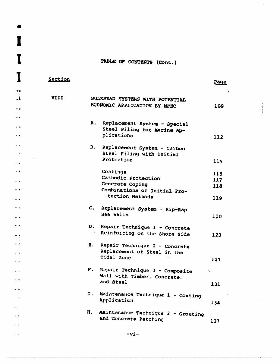
SVIII BULKfIEAD SYSTEMS WITH POTENTIALECONOMIC APPLICATION BY NFEC 109
A. Replacement System - Special"Steel Piling for Marine Ap-plications 112
"B. Replacement System - CarbonSteel Piling with InitialProtection 115
Coatings 115Cathodic Protection 117Concrete Coping 118-- Combinations of Initial Pro-
tection Methods 119
C. Replacement System - Rip-RapSea Walls i•0
D. Repair Technique 1 - ConcreteReinfoicing on the Shore Side 123
"" R. Repair Technique 2 - ConcreteReplacement of Steel in theTidal Zone 127
F. Repair Technique 3 - CompositeWall with Timber, Concrete,"" and Steel 131
SG Maintenaiice Technique 1 - Coating
"Application 134
H. Maintenance Technique 2 - Grouting"and Concrete Patching 137
-vi-
Th= CU' CO9TUT (Cont.) TSRage|
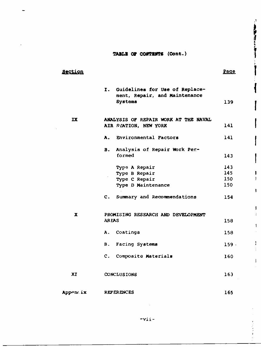
I. Guidelines for Use of Replace-ment, Repair, and MaintenanceSystems 139 1
IX ANALYSIS OF REPAIR WORK AT THE NAVALAIR STfATION, NEW YORK 141 IA. Environmental Factors 141
B. Analysis of Repair Work Per-formed 143
Type A Repair 143Type B Repair 145Type C Repair 150Type D Maintenance 150
I
C. Summary and Recommexndatione 54
X PROMISING RESEARCH AND DEVELOPMENTAREAS 158
A. Coatings 158
B. Facing Systems 159.
C. Composite Materials 160
XI CONCLUSIONS 163
App-nr. ix REFERENCES 165
-vii-
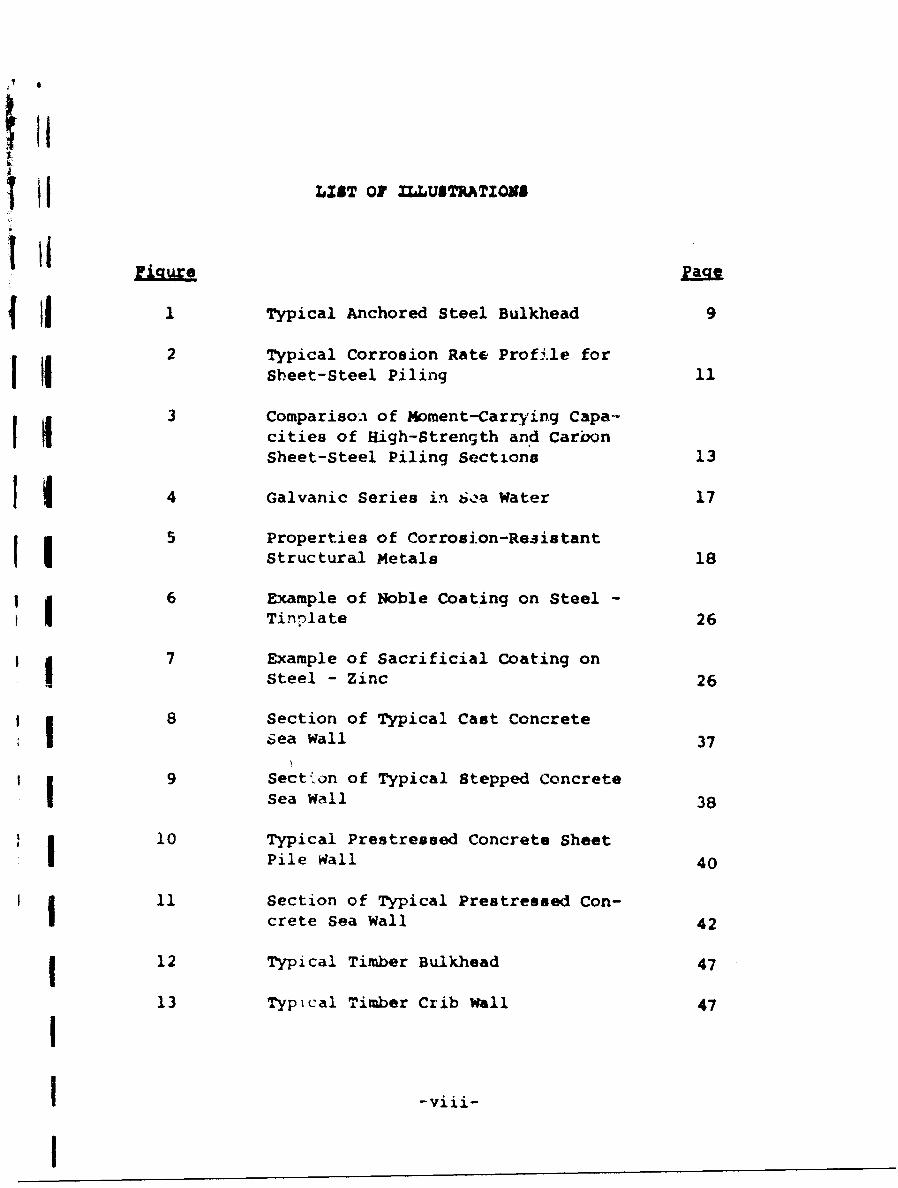
'ill II LIST 0OF ILLUSTRATIONS
41 Typical Anchored Steel Bulkhead 9
2 Typical Corrosion Rate Profile forHi Sheet-Steel Piling 11
3 Comparison of Moment-Carrying Capa-i cities of High-Strength and Carbon
Sheet-Steel Piling Sections 13
4 Galvanic Series in 6,-,a Water 17
5 Properties of Corrosion-RezistantStructural Metals 18
6 Example of Noble Coating on Steel -! Tinnlate 26
I |7 Example of Sacrificial Coating onSteel - Zinc 26
8 Section of Typical Cast ConcreteI Sea wall 37
* 9 Section of Typical Stepped ConcreteSea Wall 38
S|10 Typical Prestressed Concrete SheetI Pile Rall 40
I 11 Section of Typical Prestressed Con-crete Sea Wall 42
1 12 Typical Timber Bulkhead 47
13 Typical Timber Crib Wall 47
II -viii-
I
U
I
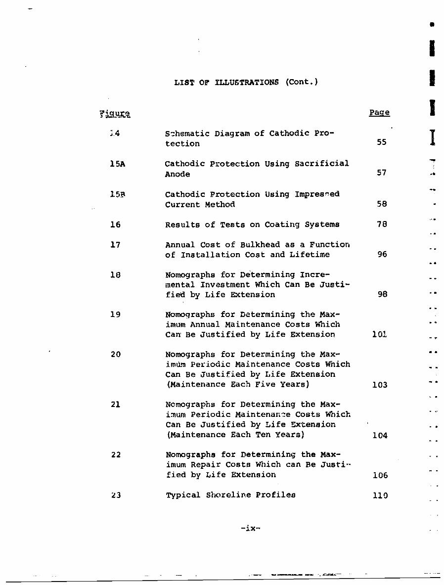
LIST OF ILLUSTRATIONS (Cont.) I
24 S:hematic Diagram of Cathodic Pro- Itection 55
15A Cathodic Protection Using SacrificialAnode 57 -,
15B Cathodic Protection Using Impresned
Current Method 58
16 Results of Tests on Coating Systems 78
17 Annual Cost of Bulkhead as a Functionof Installation Cost and Lifetime 96
18 Nomographs for Determining Incre-mental Investment Which Can Be Justi-fied by Life Extension 98
19 Nomographs for Determining the Max-imum Annual Maintenance Costs WhichCan Be Justified by Life Extension 101
20 Nomographs for Determining the Max- ".imd•m Periodic Maintenance Costs WhichCan Be Justified by Life Extension(Maintenance Each Five Years) 103 -"
21 Nomographs for Determining the Max-imum Periodic Maintenanre Costs WhichCan Be Justified by Life Extension -*
(Maintenance Each Ten Years) 104
22 Nomographe for Determining the Max-imum Repair Costs Which can Be Justi--fied by Life Extension 106
23 Typical Shoreline Profiles 110
-ix-
LIST OF ILLUSTRATIONS (Cont.)
IFigure Pa;1
24 Comparison of Annual Cost of SpecialSteel Bulkheads and Carbon SteelBulkheads 113
25 Comparison of Annual Cost of CarbonSteel Bulkhead with Initial Protectionand Annual Cost without Initial Pro-tection 116
"26 Comparison of Annual Cost of Rip-RapSea Wall with a Replacement CarbonSteel Bulkhead 121
27 Elevation Showing Type A Repairs 124
28 Comparison of Annual Cost of ConcreteReinforcing on the Shore Side (Type ARepair) with a Replacement Carbon"Steel Bulkhead 125
29 Elevation Showing Type B Repairs 128
30 Comparison of Annual Cost of ConcreteReplacement of Steel to Below MLW(Type B Repair) with a Replacement
-- Carbon Steel Bulkhead 129
31 Comparison of Annual Cost of Com-- •posite Wall with Timber, Concrete,
and Steel with a Replacement C-rbonSteel Bulkhead 132
32 Annual Cost Analysis of Periodic Ap-plications of Coatings on Sheet-SteelBulkheads 135
"33 Guidelines for Selection of Repair orReplacement Systems 140
-X_
LIST OF ILLUSTRATIONS (Cont.) IePage
34 Construction Sequence - Type A Repair 144
35 Cost Summary for Type A Repair 146
36 Construction Sequence - Type B Repair 147
37 Cost Summary for Type B Repair 149
38 Plan & Elevation Showing Type CRepairs 151
39 Cost Summary for Type C Repair 152
40 Elevation Showing Type D Maintenance, 153
41 Cost Summary for Type D Maintenance 155
42 Evaluation of Three Bulkhead Materi-"ala in Various Corrosion Zones 162
-xi-
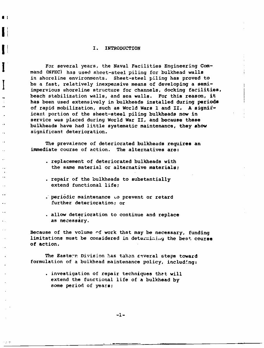
I. INTRODUCTION
j For several years, the Naval Facilities Engineering Com-
a mand (NFEC) has used sheet-steel piling for bulkhead walls
in shoreline environments. Sheet-steel piling has proved tobe a fast, relatively inexpensive means of developing a semi-I impervious shoreline structure for channels, docking facilities,beach stabilization walls, and sea walls. For this reason, ithas been used extensively in bulkheads installed during periodsof rapid mobilization, such as World Wars I and II. A signif-icant portion of the sheet-steel piling bulkheads now inservice was placed during World War II, and because thesebulkheads have had little systematic maintenance, they showsignificant deterioration.
The prevalence of deteriorated bulkheads requires animmediate course of action. The alternatives are:
replacement of deteriorated bulkheads withthe same material or alternative materials;
repair of the bulkheads to substantiallyextend functional life;
• periodic maintenance Lo prevent or retardfurther deterioration; or
allow deterioration to continue and replaceas necessary.
Because of the volume nf work that may be necessary, fundinglimitations must be considered in deteLiiy the best courseof action.
The Eastern Division has takan Eiveral Gteps towardformulation of a bulkhead maintenance policy, includ!ng:
investigation of repair techniques that willextend the functional life of a bulkhead bysome period of years;
-l-1-
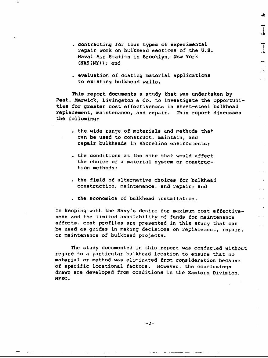
"contracting for four types of experimentalrepair work on bulkhead sections of the U.S.Naval Air Station in Brooklyn, New York(NAS (NY)); and
"* evaluation of coating material applicationsto existing bulkhead walls.
This report documents a stuldy that was undertaken byPeat, Marwick, Livingston & Co. to investigate the opportuni-ties for greater cost effectiveness in sheet-steel bulkheadreplacement, maintenance, and repair. This report discussesthe following:
". the wide range of materials and methods thatcan be used to construct, maintain, andrepair bulkheads in shoreline environments;
". the conditions at the site that would affectthe choice of a material system or construc-tion methods;
"* the field of alternative choices for bulkheadconstruction, maintenance, and repair; and
"* the economics of bulkhead installation.
In keeping with the Navy's desire for maximum cost effective-ness and the limited availability of funds for maintenanceefforts, cost profiles are presented in this study that canbe used as guides in making decisions on replacement, repair,or maintenance of bulkhead projects.
The study documented in this report was conducted withoutregard to a particular bulkhead location to ensure that nomaterial or method was eliminated from consideration becauseof specific locational factors. however, the conclusionsdrawn are developed from conditions in the Eastern Division,NFEC.
-2-
A
A
II. SUMMARY
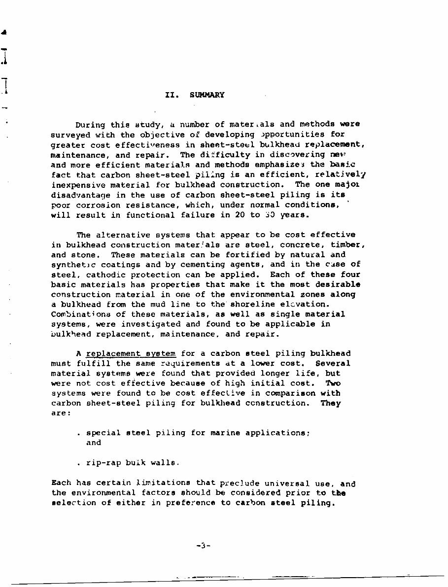
During this study, a number of materials and methods weresurveyed with the objective of developing •pportunities forgreater cost effectiveness in sheet-steel bulkhead replacement,maintenance, and repair. The difficulty in discovering newand more efficient materials and methods emphasize3 the basicfact that carbon sheet-steel piling is an efficient, relattvelyinexpensive material for bulkhead construction. The one majoidisadvantage in the use of carbon sheet-steel piling is itspoor corrosion resistance, which, under normal conditions,will result in functional failure in 20 to 30 years.
The alternative systems that appear to be cost effectivein bulkhead construction materials are steel, concrete, timber,and stone. These materials can be fortified by natural andsynthetic coatings and by cementing agents, and in the case ofsteel, cathodic protection can be applied. Each of these fourbasic materials has properties that make it the most desirableconstruction material in one of the environmental zones alonga bulkhead from the mud line to the shoreline elevation.Combinations of these materials, as well as single materialsystems, were investigated and found to be applicable inbulkhead replacement, maintenance, and repair.
A replacement system for a carbon steel piling bulkheadmust fulfill the same requirements dt a lower cost. Severalmaterial systems were found that provided longer life, butwere not cost effective because of high initial cost. Twosystems were found to be cost effecLive in comparison withcarbon sheet-steel piling for bulkhiead construction. Theyare:
"• special steel piling for marine applications;
and
"* rip-rap buALk walls.
Each has certain limitations that preclude universal use, andthe environmental factors should be considered prior to theselection of either in preference to carbon steel piling.
3-
Some protection methods applicable to carbon steelbulkheads at installation proved to be cost effective. Twomethods explored at length were:
"* cathodic protection; and
". impervious organic coatings.
Each of these methods can be applied during construction ata cost increment of less than 10 percent above normal cost.Each method appeared to extend life by 5 or more years, whichwill ordinarily justify their use. The combination of thesetwo methods may offer additional life extension, but thiscombination is only marginally cost effective.
Maintenance for sheet-steel bulkheads must be inexpensiveand effective in extending bulkhead life. The following twotechniques met these criteria:
coating applications at intervals of severalyears; and
. grouting or concrete patching as required.
These two methods can be used periodically to extend life, butthe amount of time between the maintenance work must beselected to maximize protection against corrosion while mini-mizing application costs. Annual maintenance for bulkheadsdoes not appear to be efficient. Five years appears to be theminimum period between maintenance projects for the optimumprotection at lowest cost.
Three repair techniques for sheet-steel bulkheads were
found to be cost effective. They are:
* concrete reijif. rcing on the steel side;
. concrete replacement of steel in the tidalzone; and
composite construction of timber sheeting,concrete, and steel.
-4-
These techniques utilize the structural strength of therelatively uncorroded sections of steel in the existing steelpiling and strengthen the piling with new materials in areasof advanced corrosion. Thi cost of these repair techniquesis 50 to 75 percent of the cost of new carbon steel bulkheadreplacements, but life extension in some cases approachesthe functional life of a carbon steel bulkhead replacement.
The cost effectiveness of several materials and methods,which might be used in bulkhead construction, is limited bytechnological and economic barriers. Development of newfacing systems, new composite materials, and new underwaterapplication methods could result in more efficient bulkheadsystems. Research into these areas is warranted.
--5--
II
III. METHODS AND MATERIALS USED iN BULKHEAD CONSTRUCTION
The three types of bulkheads considered in this reportcan be identified in terms of their structural configurationas follows:
. cantilever systems;• anchored systems; and. bulk walls.
The simplest cantilever system is a bulkhead wall con-
sisting of a line of sheet piling that is sufficiently
embedded below the dredge line to resist the overturning
forces caused by the upland fill without assistance from a
tieback. Use of such a cantilever wall L6 limited to sites
with relatively shallow water, low embankment height, and
low surcharge loadings on top of the retained earth. A
second type of cantilever system employs discrete soldier
piles for lateral resistance, with sections of sheet piling
or lagging between soldiers.
For greatbr bulkhead heights or higher earth pressures,
anchored systems are generally used. An anchored bulkhead
consists of a wall of sheet piling embedded below the dredge
line and restrained near the top by an anchorage system to
prevent outward movement. The anchorage system is typicallya series of discrete anchors used to tie back a wale fas-
tened to the piling and extending the length of the wall.
When heavy surcharge loads are to be supported or a great
depth of water is required at the face of the bulkhead, the
bulkhead may be constructed with a relieving platform, toreduce the lateral effects.
Bulk walls are generally massive gravity structures
designed to resist both the lateral earth pressur-s and thewave action of the sea. They may be vertical, or they may
have a curved or stepped face. When a wave breaks on a bulksea wall, the energy moves the water downward with a force
that erodes the sand at the toe of the -'i41. Bulk walls,
therefore, must be carried to sufficie t depth -o protect
the stability of the wall and ito reta i. ea-th.
-6-
a
I
Several alternative materials are available for con- Ist 'tion of these bulkheads. The traditional materialsincude steel, concrete, timber, and stone. In the follow-ing pages of this section, various alternative systems forinitial installation of s)-ore-pro3tection bulkheads aredescribed. For the purposes of this report, the alternativesystems have been grouped by basic material of construction,and the types of bulkheads appropriate fcr each materialare treated within the discussion on that material.
I
I!IIII
A. Steel Piling
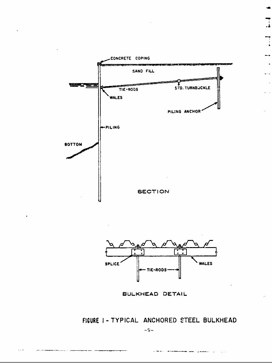
Bulkheads of metal consist of a series of rolled sec-tions imbedded into the earth and interlocked to form acantilevered or anchored wall. Sheet-steel piling-thetraditional material used for metal bulk)eads-is producedin three shapes and in graduated weights to economicallymeet various design requirements. The three shapes-straightweb, arch web, and Z piling-have interlocking edges, whichare continuous throughout their entire length. A typicalanchored sheet-steel piling installation is illustratedin Figure 1.
Carbon Steels
Con%- lntional sheet-steel piling is produced from carbonsteel alloys conforming to ASTH Specification A328. Thesesteels have a minimum yield stless of 38,500 psi, a minimumtensile strength of 70,000 psi, and an allowable designworking stress of 24,000 psi. Conventional sheet-steelpiling installed in sea water has often been used withoutany form of protective coating and has provided reasonablelengths of service, even though serious corrosion hasoccurred under such circumstances.
Sheet-steel piling in sea water installatiC.,d is exposedto differing conditions in the following six zones along itsheight:
I I . atmospheric zone:. splash zone;. tidal zone;. active electrolytic zone;. underwater zone; and. imbedded zone.
In the atmospheric zone, the steel is subjected to attack byairborne corrosives, and if the steel is unprotected, thenormal oxidation process results in rusting. In the splashzone, the corrosion process is similar, but is greatly ac-celerated by the presence of a thin film of eea water. Thecorrosion process ia an electrochemical reaction in whichiron ions combine with the oxygen and hydrogen in the waterIi
Ii
CONCRETE COPING
SAND FILL
""I-RD STD. TURNBJCKLE
PILING
ANCHOR
-PILING
BOTTOM
SECTION
SPLICE WALES
b TIE-RODS---
BULKHEAD DETAIL
FIGURE I -TYPICAL ANCHORED STEEL BULKHEAD
and the air to form rust. Since a good electrolyte ispresent in the sca water and there is a plentiful supply ofoxygen available from the air, corrosion proceeds at a highrate in the splash zone. In the tidal zone, the steel isgenerally subject to less severe corrosion than in thesplash zone because of the periodic submergence of thesteel, which results in a decreased oxygen supply in com-parison with the splash zone. In addition, the steel inthe regior very nea: the water surface is cathodic to anarea some Listance below the water su-face.
Because of continual wave action, the water near theactive electrolytic zone normally retains a considerablyhigher entrapped oxygen content than water at greater' dis-tances from the surface. This situation leads to the forma-tion of an oxygen concentration cell, in which the areawhere oxygen is less available becomes the anode, and thecathoee is formed where oxygen is abundantly available.Iron ions continually go into solution in the sea waterelectrolyte at the anode, thus leading to a gross loss ofmetal in the region just below the oxygen-rich surfacelayer. This concentration cell can be controlled by theuse of cathodic protection, a modification to the electro-chemical system which overrides the concentration cell byimposing a current between the sheet-steel piling and asacrificial anode. (See Section IV for a detailed discus-sion of cathodic protection.)
Below the active electrolytic zone, the cor'rcsion rateis relatively smnall. This region is continually wet, andits oxygen content is uniformly minimal. In circumstanceswhere looee m~aterial is transported along the ocean bottomby water currents, however, substantial erosion may occur.Th3 portion of the steel piling embedded in the mud isgeneraliy protected against both corrosion and erosion bythe mud, with the poEsible exception that abrasion some-times occurs during driving, causing minor losses of metal.
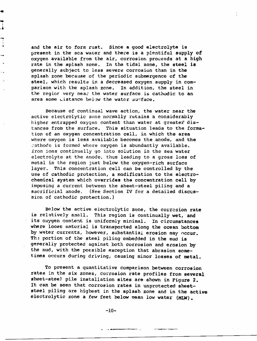
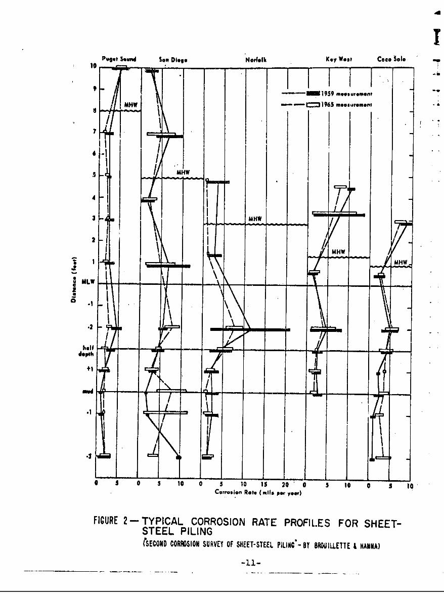
To present a quantitative comparison between corrosionrates in the six zones, corrosion rate profiles from severalsheet-steel pile installation sites are shown in Figure 2.It can be seen that corrosion rates in unprotected sheet-steel piling are highest in the splash zone and in the activeelectrolytic zone a few feet below mean low water (MLw).
-10-
Puget Sund Sen D0ego Norfolk Key West Coco Solo1°.. .. . I I I I~ *-- i ; 1959 meseurement
MHW C J )965 meos tromont
I '
'--I I •
I HMHW
I L- HW ,I
2I
1 MHW
MLW ....- \-.
.2 \I\/•. If 7-
depth
+1 I .md -- r- - --' -
I I
II.3 C
0 5 10 0 5 10 15 20 0 5 10 0 3 10Corrolion Rate (mils pwe' yet)
FIGURE 2- TYPICAL CORROSION RATE PROFILES FOR SHEET-STEEL PILING(SECOND CORROSION SURVEY OF SHEET-STEEL PILINC--BY BROUILLETTE H HANNA)
-i..1-
It should be noted that local severe corrosion of sheet-steel piling does not necessarily result in catastrophicfailure of the bulkhead structure. Even local perforationof the bulkhead piling in the splash zone or active electro-lytic zone leaves substantial portions of the bulkheadrelatively intact. One beneficial factor in anchored bulk-head design is that maximum bending stresses generally occurat a point below the areas where corrosion most weakens thesheet piling. Stresses may go above the design workingstresses as material losses occur, but catastrophic failurewill not occur until the safety factor has been used up andthe ultimate strength of the steel is exceeded. Local per-foration may, however, lead to loss of backfill material,and if this condition is seriously detrimental to the func-tion of the bulkhead, corrective measures will be requiredaside from structural considerations.
High-Strength Steels
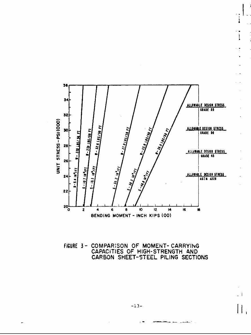
In the late 1950's and early 1960's, a new family ofsteels was added to the traditional carbon steels: low-alloy steels characterized by higher strengths and, there-fore, higher allowable working stresses. Typical mechanicalproperties for high-strength steel used for sheet piling areof a minimum tensile strength of 70,000 psi, a minimum yieldstrength of 50,0%0 psi, and a working stress of 30,000 psi.It should be noted that this working stress is 25 percenthigher than that for carbon steels, so that a given sheetpiling section will have greater moment-carrying capacity.Figure 3 illustrates, for three grades of high-strengthsteel, the increase in moment-carrying capacity for a numberof typical sheet piling sections.
The high-strength steels cost approximately 15 percentmore than carbon steels, but this cost disadvantage can beoutweighed by the increase in load-carrying capacity. Withrespect to corrosion, however, the high-strength steels haveno advantage over the carbon steels. In sheet piling appli-cations, in fact, corrosion and erosion can have a moredamaging effect on high-strength steel piling. Since high-strength steel piling sections are relatively thinner thancarbon steel piling for the same moment-carrying capacity,a loss of a given number of mile of steel because of corrosionwill effect a greater reduction in load-carrying capacity inhigh-strength steel piling.
-12-
36
34-
A.LLOWA LE DESIG WTRES$6,1A0E 5
32-
28
Li- .ALLOQI*E DES1IG STRES$GIADE 45• 26- I
2s-Z " .
24 .- ALLO E I K SRS
N2 - "AST" AM
220
0 2 4 6 8 10 12 14 16 a
BENDING MOMENT - INCH KIPS (00)
FIGURE 3- COMPARISON OF MOMENT- CARRYINGCAPACITIES OF HIGH-STRENGTH ANDCARBON SHEET-STEEL PILING SECTIONS
-1I3
Special Steel for Marine ApRlications 1
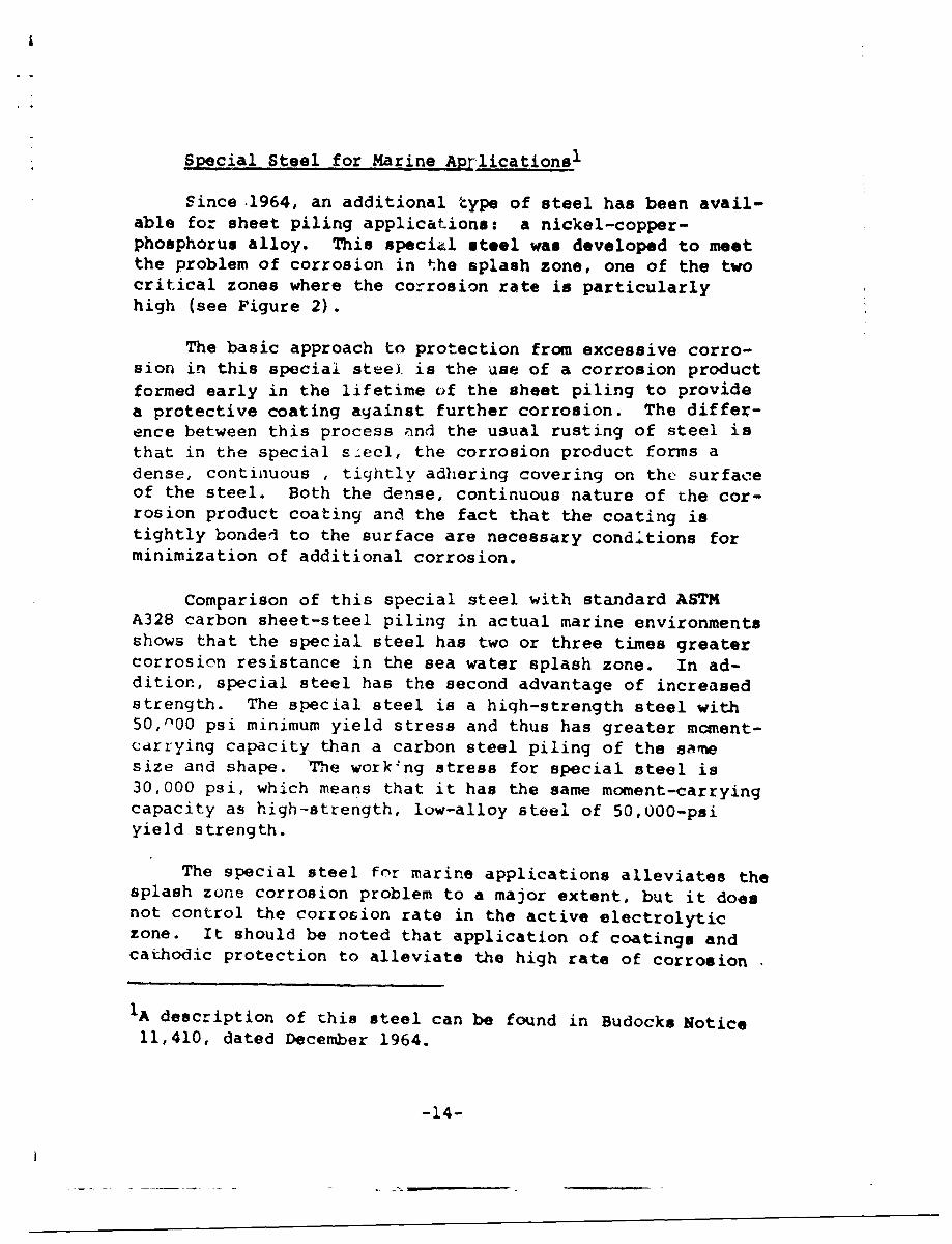
Since 1964, an additional type of steel has been avail-able for sheet piling applications: a nickel-copper-phosphorus alloy. This special steel was developed to meetthe problem of corrosion in the splash zone, one of the twocritical zones where the corrosion rate is particularlyhigh (see Figure 2).
The basic approach to protection from excessive corro-sion in this special steel is the use of a corrosion productformed early in the lifetime of the sheet piling to providea protective coating against further corrosion. The differ-ence between this process and the usual rusting of steel isthat in the special s~eel, the corrosion product forms adense, continuous , tightly adhering covering on the surfaceof the steel. Both the dense, continuous nature of the cor-rosion product coating and the fact that the coating istightly bonded to the surface are necessary condi.tions forminimization of additional corrosion.
Comparison of this special steel with standard ASTMA328 carbon sheet-steel piling in actual marine environmentsshows that the special steel has two or three times greatercorrosion resistance in the sea water splash zone. In ad-dition, special steel has the second advantage of increasedstrength. The special steel is a hiqh-strength steel with50,000 psi minimum yield stress and thus has greater moment-cdrrying capacity than a carbon steel piling of the samesize and shape. The work~ng stress for special steel is30,000 psi, which means that it has the same moment-carryingcapacity as high-strength, low-alloy steel of 50,000-psiyield strength.
The special steel for marine applications alleviates thesplash zone corrosion problem to a major extent, but it doesnot control the corrosion rate in the active electrolyticzone. It should be noted that application of coatings andcathodic protection to alleviate the high rate of corrosion
1A description of this steel can be found in Budocks Notice11,410, dated December 1964.
-14-
in the son6 just below the water surface and the use of Ispecial steel as the structural material to control thesplash zone corrosion problem provide a good combinationfor promotion of long life for the sheet piling. Coatingapplied to the piling before driving, can be expected toprotect the steel from the oxygen concentration cell attackfor three to seven years. At the time of installation ofthe bulkhead, prnvision can be made for later installationof a cathodic prctection system when the initial protectivecoating has ceased to be effective in the active electro-lytic zone.
This special steel for marine applications has two meas-urable advantages in addition to the major protection offeredin the splash zone. An impermeable and strongly adhesivecorrosion product is developed in the atmospheric zone ofthe piling as a result of initial corrosive attack from at-mospheric agents common to industrial areas. This layer ofcorrosion product protects the base steel from further cor-rosion. Also, if paint is applied to this steel upon initialinstallation to prolong the life of the piling or foraesthetic reasons, it will last roughly twice as long as thesame coating would on conventional carbon steel piling. Thisbenefit is derived from the low volume and consistent thick-ness of the corrosion product* which in contrast to carbonsteel, is not disruptive to the paint or other coating inthe vicinity of the scratch or other break in the coating.
-15-
B. Corrosion-Resistant Structural Metals
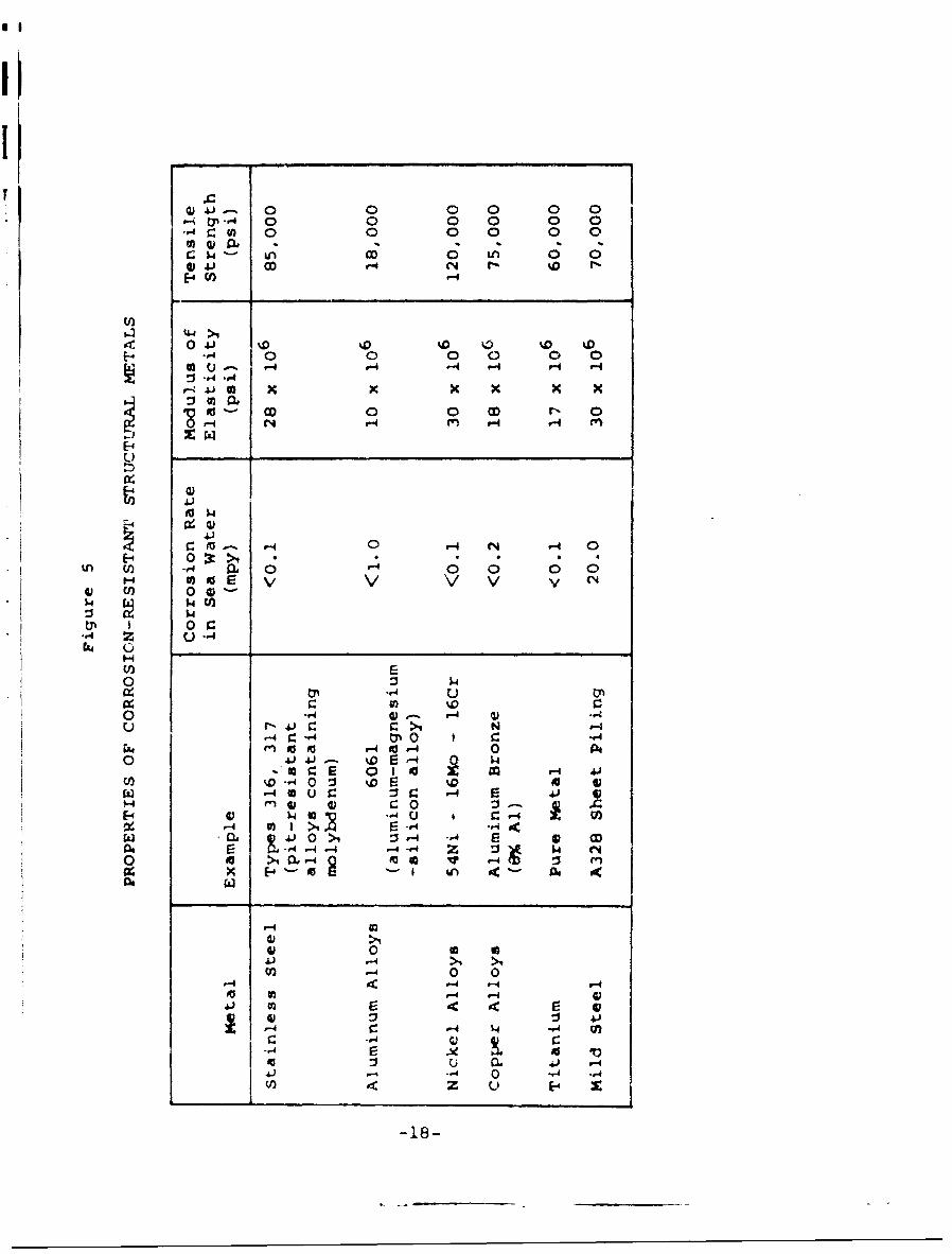
Several metals having the same strength and stiffnessvalues as the structural steels have considerably betterresistance than steel to corrosion attack in sea water. Afirst approach to identifying materials that might fall intothis category can be made by employing the galvanic seriesin sea water (see Figure 4 for a listing of metals in orderof their relative potential for corrosion in sea water).Any material above mild steel on this galvanic series wouldbe a candidate for use as the structural metal frcm whichbulkheads could be constructed, if the material also met thecriteria of necessary strength and stiffness and were avail-able at reasonable cost. Several of the more promisingcorrosion-resistant metals with good structural propertiesare listed in Figure 5. The detailed corrosion behavior ofeach of these structural metals is discussed below.
Stainless Steel
Alloying is an effective means for improving the resist-ance of metals to attack by corrosive environments. Alloyingis particularly effective in improving corrosion resistanceif passivity results from the combination of a metal that isotherwise active with a normally passive metal. 1 For example,iron alloyed with chromium becomes passive through the processii of self-corrosion. In homogeneous single-phase alloys,passivity usually occurs above a limiting composition that isspecific to each alloy and may also be depeident upon theenvironment. For iron alloyed with chromium, the criticalcomposition for passivity comes at about 12-percent chromium.Ferrous alloys having at least this amount of chromium areapproximately as passive as chromium itself and are calledstainless steels.
It1A metal that is normally active in the galvanic series or
i I I an alloy composed of such metals is called passive when itselectrochemical behavior becomes that of an appreciably lessactive metal. Passivity may be due to a thin film such asan oxide, an adsorbed film of oxygen or other gas or of ions,or it may be due to the electron configuration of the atoms.
I16-16-
I1:
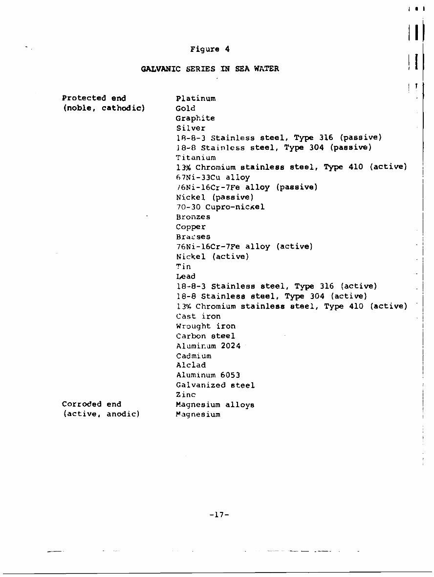
Figure 4
GALVANIC SERIES IN SEA WATER
Protected end Platinum(noble, cathodic) Gold
GraphiteSilver18-8-3 Stainless steel, Type 316 (passive)18-8 Stainless steel, Type 304 (passive)Titanium13% Chromium stainless steel, Type 410 (active)67Ni-33Cu alloy/6Ni-16Cr-7Fe alloy (passive)Nickel (passive)70-30 Cupro-nice elBronzesCopperBra.ses76Ni-16Cr-7Fe alloy (active)Nickel (active)TinLead18-8-3 Stainless steel, Type 316 (active)18-8 Stainless steel, Type 304 (active)13% Chromium stainless steel, Type 410 (active)Cast ironWrought iron
Carbon steelAluminum 2024CadmiumAlcladAluminum 6053Galvanized steelZinc
Corroded end Magnesium alloys(active, anodic) Magnesium
-17-
0- N-4 00 00 g 0 a
U)U0 44
4.1~ 0 D%0%
E- .,O '0 '0 0 0:3. -,4-,
r -4 41 xx xx
04 E N V-4 r-4.-4m
o0 0
r-4 0¶ >1 r
'.4 0 0
-A 4: 4:r.4J
tp '.4 u .4. f
C -4 ri 0-r
r. ~ ~ ' 0 F4
-4 Q U -44
4) -18-

III
The corrosici resistance of the qtainless steels is due I Ito the formation of a thin passivatiny film on the metalsurf ice. Such a film forms spontaneously from contact of aclean metal surface with dry air for a period of severaldays, or from short time-exposure with an oxidizing agentst'ch as nitric acid. When ýhe pasr!.ated surface is i.nersedin water containing oxygen, a dynamic equilibrium is set upbetween breakdown and repair of the film. Maintenance ofpassivity requires the continuous replenishment of theoxidizinq agent. Dissolved oxyien in rea water is sufficientto maintain passivity on clear Purfaces, "ut the metal becomesactive in areas where repair of ie iilm is prevented by lackof access to oxygen. li Lu, severe cc -csion and pitting ofstainless steel, comparable with that if iron or mild steel,can take place beneath debris, larnacles, or in crevices.
Although stainless st, I is usually not attacked gal-vanically, it may accelercte attack on a less noble metalto which it is connected because of its strongly cathodicnature. In sea water, stai iless steel behaves like any othercathode material in caus-' .g galvanic attack on any anodicmetal -onnected to it in a couple.
There is little advantage in using stainless steelinstead of ordinary steel in relatively stagnant sea water,,ince fouling takes place and deep pitting results. Inrapidly moving sea water, however, fouling does not occur,and aeration is sufficiently strong to maintain the passivat-ing film. Under such conditions, the pitting of stainlesssteels be-omes negligible, while the corrosion rate of mildsteel would be increased. For exposure conditions betweenstan.ant sea water and high velocities, the performance ofstainless steels varies. Pit-resistant alloys containingmolybdenum are superior to other compositions in thiscxposure range.
The appLication of stainless steels to shore protectionstructures does not seem justified. The problems of pittingcaused by fouling, intergranular corrosion, stress-corrosioncracking, and galvanic attack of connected metals are seriousand inherent to the stainless stenls presently available.In addition, the initial cost of stainless steel and the in-creased difficulty in fabricating it weigh against its use.
-19-
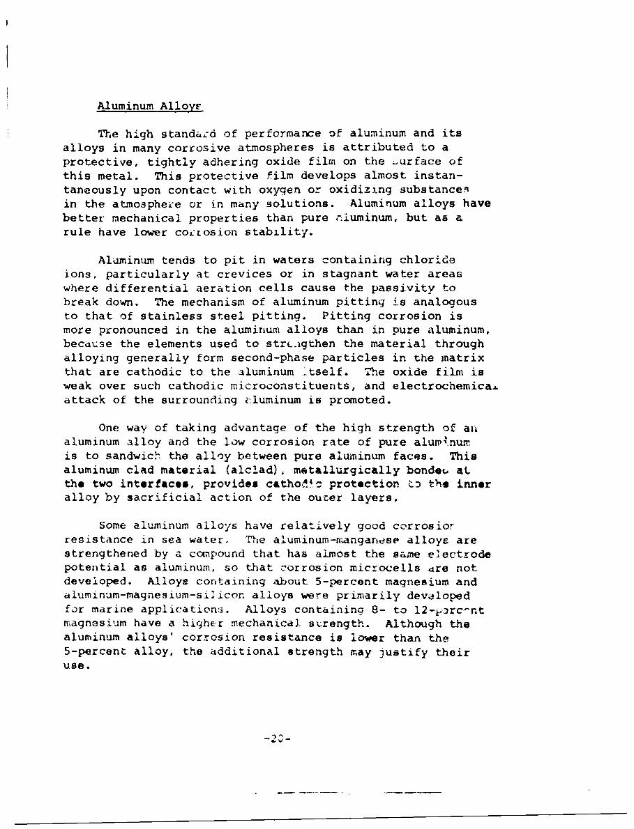
Aluminum Alloyr
The high standazd of performance of aluminum and itsalloys in many corrosive atmospheres is attributed to aprotective, tightly adhering oxide film on the -urface ofthis metal. This protective film develops almost instan-taneously upon contact with oxygen or oxidizing substancesin the atmosphei'e or in many solutions. Aluminum alloys havebetter mechanical properties than pure r.luminum, but as arule have lower coctosion stability.
Aluminum tends to pit in waters containing chlorideions, particularly at crevices or in stagnant water areaswhere differential aeration cells cause the passivity tobreak down. The mechanism of aluminum pitting is analogousto that of stainless steel pitting. Pitting corrosion ismore pronounced in the aluminum alloys than in pure aluminum,because the elements used to strLcgthen the material throughalloying generally form second-phase particles in the matrixthat are cathodic to the aluminum .tself. T-he oxide film isweak over such cathodic microconstituents, and electrochemicaA.attack of the surrounding i.luminum is promoted.
One way of taking advantage of the high strength of analuminum alloy and the low corrosion rate of pure alumrinumis to sandwich' the alloy between pure aluminum faces. Thisaluminum clad material (alclad), motallurgically bonde(, atthe two interfaces, provides catho.dc protection t: tle inneralloy by sacrificial action of the outer layers.
Some aluminum alloys have relatively good corrosiorresistance in sea water. The aluminum-wanganrse alloys arestrengthened by a compound that has almost the s&zme electrodepotential as aluminum, so that corrosion microcells dre notdeveloped. Alloy: containing about 5-percent magnesium andaluminum-magnesium-silicon alloys were primarily developedfor marine applications. Alloys containing 8- to 12-1,rc-ntmagnesium have a higher mechanical sarength. Although thealuminum alloys' corrosion resistance is lower than the5-percent alloy, the additional strength may justify theiruse.
-2 ,-
4}
-wa -
Aluminuim alloys evaluated in sea water and harbor waterseffectively maintained tensile strength over a long exposureperiod. The alclad alloys and magnesium-containing alloyswere the most resistant.
Since reliable corrosion-resistant aluminum alloys canbe found for the sea water environment, comparison betweenthese materials and other candidates must be made on the basisof cost and mechanical properuy parameters. Since aluminumalloys are more costly than structural steels and have lowerstrength and stiffness characteristics, their applicabilityis quastionacle.
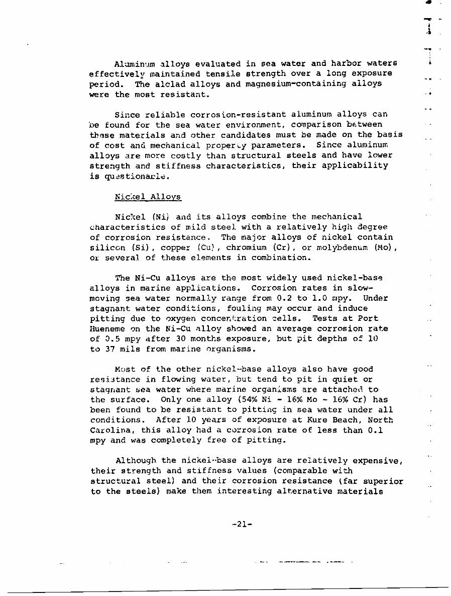
Nickel Alloys
Nickel (Ni) and its alloys combine the mechanicalcharacteristics of mild steel with a relatively high degreeof corrosion resistance. The major alloys of nickel containsilicon (Si), copper (Cu), chromium (Cr), or molybdenum (Mo),or several of these elements in combination.
The Ni-Cu alloys are the most widely used nickel-basealloys in marine applications. Corrosion rates in slow-moving sea water normally range from 0.2 to 1.0 mpy. Understagnant water conditions, fouling may occur and inducepitting due to oxygen concentration zells. Tests at PortHueneme on the Ni-Cu alloy showed an average corrosion rateof 0.5 mpy after 30 months exposure, but pit depths of 10to 37 mils from marine organisms.
Most of the other nickel-base alloys also have goodresistance in flowing water, but tend to pit in quiet orstagnant sea water where marine organisms are attached tothe surface. Only one alloy (54% Ni - 16% Mo - 16% Cr) hasbeen found to be resistant to pitting in sea water under allconditions. After 10 years of exposure at Kure Beach, NorthCarolina, this alloy had a corrosion rate of less than 0.1mpy and was completely free of pitting.
Although the nickeli-base alloys are relatively expensive,their strength and stiffness values (comparable withstructural steel) and their corrosion resistance (far superiorto the steels) make them interesting alternative materials
-21-
f-r bulkhead construction. Despite high initial cost, useof nickel alloys should be seriously considered when longlife is desired and maintenance may be neglected.
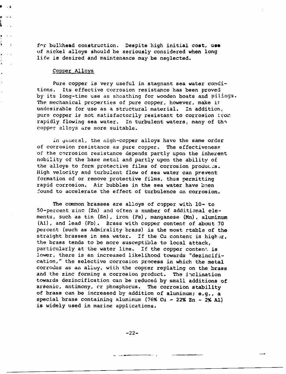
Copper Alloys
Pure copper is very useful in stagnant sea water condi-tions. Its effective corrosion resistance has been provedby its long-time use as sheathing for wooden boats and pilings.The mechanical properties of pure copper, however, make itundesirable for use as a structural material. In addition,pure copper ie not satisfactorily resistant to corrosion itojr-rapidly flowing sea water. In turbulent waters, many of thicopper alloys are more suitable.
in 9Eyaera!, the nigh-copper alloys have the same orderof corrosion resistance as pure copper. The effectivenessof the corrosion resistance depends partly upon the inherentnobility of the base metal and partly upon the ability ofthe alloys to form protective films of corrosion produc.s.High velocity and turbulent flow of sea water can preventformation of or remove protective films, thus permittingrapid corrosion. Air bubbles in the sea water have bnenfound to accelerate the effect of turbulence on corrosion.
The common brasses are alloys of copper with 10- to50-percent zinc (Zn) and often a number of additional ele-ments, such as tin (Sn), iron (Fe), manganese (Mn), aluminum(Al), and lead (Pb). Brass with copper content of about 70percent (such as Admirality brass) is the most stable of thestraight brasses in sea water. If the Cu content is highýer,the brass tends to be more susceptible to local attack,particularly at the water line. If the copper content. islower, there is an increased likelihood towards "dezincifi-cation," the selective corrosion process in which the metalcorrodes as an alloy, with the copýer replating on the brassand the zinc forming a corrosion product. The iiclinationtowards dezincification can be reduced by small additions ofarsenic, antimony, cr phosphorus. The corrosion stabilityof brass can be increased by addition of aluminum; e.g., aspecial brass containing aluminum (76% Cu - 22% Zn - 2% Al)is widely used in marine applications.
-22-

-w
The aluminum bronzes usually contain not more than 9-to 10-percent aluminum and sometimes small additions ofmanganese and nickel. In sea water, the aluminum bronzeshave higher stability tnan thG other copper alloys, withcorrosion rates only 1/10 those of copper-tin bronzes and1/30 these of brasses. Complex alloys of this class areused in the manufacture of ship screws, in which they offerstability against erosion and cavitation.
Copper-nickel alloys containing from 5- to 40-percentnickel have relatively good mechaaical properties and excel-lent resistance to corrosion in sea water. Most attentionhas been directed to the corrosion-resistance improvementunder flow conditions obtained by small additions of ironand manganese.
The most prevalent applications of the copper alloys insea water envirounments have been in such places as power-plant tubing on ships. Although corrosion rates can be heldto values considerably smaller than those observed in steelstructures, this desirable characteristic seems to be out-weighed by the lower values of strength and stiffness andthe ever-present consideration of increased initial instal-lation cost.
Titanium
This relatively new structural metal has excellent cor-rosion resistance and a high strength-to-weight ratio. Tita-nium owes its corrosion resistance to a protective oxide film,which has outstanding resistance to corrosion and pitting inmarine environments. It is not antifouling, but there is nopitting or crevice corrosion from fouling organisms.
The high corrosion resistance of titanirT- is due to thestability of the passive state. In this state, titaniuta isresistant to oxygen-rich bolutions and to solutions containinghigh concentrations of chloride ions (i.e., it is res qtantto stress corrosion cracking in chloride solutions that wouldproduce failure in 18/8 stainless steel in a few hours). Theresistance of titanium to corrosion and pitting in both stag-nant and moving sea water approaches the resistance of thenoble metals. Only very slight uniform loss (0.0001 ipy)occurs over several years of exposure.
-23-
The major drawback of titanium metal is the complicatedprocessing necessary to obtain it in a reasonably pure form.Titanium is difficult and expensive to refine because of itshigh reactivity at elevated temperatures and its relativelyhigh melting point. Although the present cost of thismaterial makes it prohibitive for general use in bulkheadconstruction, its mechanical properties and corrosion resist-ance recommend it for use in critical situations.
-24-
iI
II
C. metallic Coatings HIn addition to the use of corrosion-resistant structur-
al metals in the construction of metal bulkheads, it is also I!possible to use the same corrosion-resistant metals or othermetals as thin coatings for the protection of a structuralmetal in the marine environment.
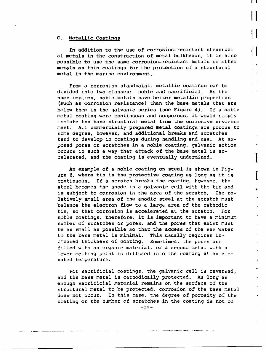
From a corrosion standpoint, metallic coatings can bedivided into two classes: noble and sacrificial. As thename implies, noble metals have better metallic properties(such as corrosion resistance) than the base metals that arebelow them in the galvanic series (see Figure 4). If a noblemetal coating were continuous and nonporous, it would simplyisolate the base structural metal from the corrosive environ-ment. All commercially prepared metal coatings are porous tosome degree, however, and additional breaks and scratchestend to develop in coatings during handling and use. At ex-posed pores or scratches in a noble coating, galvanic actionoccurs in such a way that attack of the base metal is ac-celerated, and the coating is eventually undermined. j
An example of a noble coating on steel is shown in Fig-ure 6, where tin is the protective coating as long as it iscontinuous. If a scratch breaks the coating, however, thesteel becomes the anode in a galvanic cell with the tin andis subject to corrosion in the area of the scratch. The re-latively small area of the anodic steel at the scratch mustbalance the electron flow to a large area of the cathodictin, so that corrosion is accelerated aL the scratch. Fornoble coatings, therefore, it is important to have a minimumnumber of scratches or pores, and the pores that exist mustbe as small as possible so that the access of the sea waterto the base metal is minimal. This usually requires in-creased thickness of coating. Sometimes, the pores arefilled with an organic material, or a second metal with alower melting point is diffused into the coating at an ele-vated temperature.
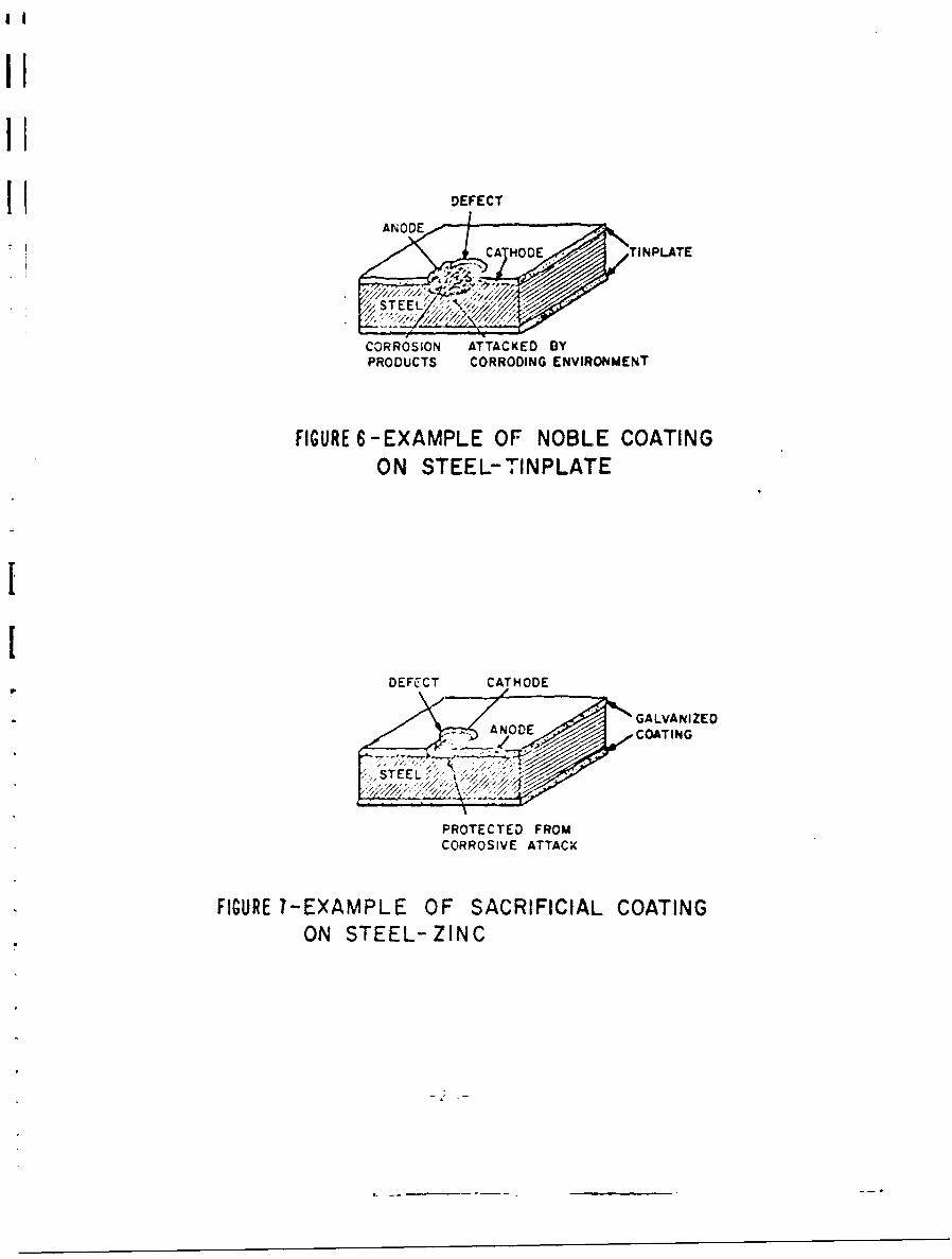
For sacrificial coatings, the galvanic cell is reversed,and the base metal is cathodically protected. As long asenough sacrificial material remains on the surface of thestructural metal to be protected, corrosion of the base metaldoes not occur. In this case, the degree of porosity of thecoating or the number of scratches in the coating is not of
-25-
DEFECTI ANODE
CA MOD TINPLATE
CORROSION ATTACKED DYPRODUCTS CORRODING ENVIRONMENT
FIGURE 6-EXAMPLE OF NOBLE COATINGON STEEL-TINPLATE
DEFECT CATHODE
GALVANIZED- 7 ANODE COATING
, STEEL :
PROTECTED FROMCORROSIVE ATTACK
FIGURE 7-EXAMPLE OF SACRIFICIAL COATINGON STEEL-ZINC
5
great importance. An example of a sacrificial coating onsteel is shown in Figure 7. In the illustration, a zinccoating is applied to form the combination known as gilva-nized-steer. The zin:, which is anodic to steel in thegalvanic series (see Figure 4), serves as the anode. Thecathodic steel is protected even where it is exposed at ascratch or pore. Since this sacrificial protection lastsonly as long as the coating material is present in suffi-cient quantity to keep the galvanic current flowing in thisway, the thickness of the coating determines how long thecathodic protection will continue.
Pretreatment of Surface
Before applying a metallic coating, it is absolutelynecessary to remove all scale, rust, and organic mattersuch as grease. Oxide scale and corrosion products are re-moved from metals by acid pickling or by mechanical abrasionof the surface. Chemical pickling consists of immersion ofthe metal in a dilute acid, such as 5- to 10-percent sulfuricacid, until the scale has been loosened or dissolved. Me-chanical abrasion methods for descaling include wire brush-ing, grinding, sand and grit blasting, and polishing. Ingeneral, these methods waste metal and produce surfaces some-what rougher grained than do the pickling methods. Whetherthe surface should be smooth or rough depends on the natureof the coating and the process by which it is to be applied.
Metal parts that reach the finishing stage are nearlyalways contam nated with grease, derived either from oilsemployed for temporary protection or cutting operations, orfrom lubricating oils and greases from the processing equip-ment. Grease may be removed by an alkaline bath containinga silicate, phosphate, or aluminate. After this hot degreas-ing by strongly alkaline solutions, subsequent washing to re-move all alkali traces is necessary. A second technique issolvent degreasing, where the metal is dipped into an organicsolvent such as naptha. In many cases, it is more efficientto degrease in the solvent vapor, since large amounts of sol-vent free from grease can be made to condense on the metal.Vapor degreasing involves placing the metal in the upper partof a vessel and boiling solvent in th' lower part, so thatthe liquid condensing on the metal surface drips down, carry-ing away the grease.
-27-
i
Methods of Application
.T The process through which a metal coating is applied• has a significant influence on the coating's character.
Thickness, composition, uniformity, density, continuity,and adherence of the coating are all affected by the ap-plication process. The practical parameters of protectivequality, appearance, and cost are all related to the methodof coating production.
Metallic coatings are applied by hot dipping, electro-plating, sintering, vapor deposition, metal spraying, dif-fusion, and mechanical cladding. Not all metal coatingsare readily applied by all methods, but often, two or moreprocesses for a given coating metal and base metal will beequally practical and economical.
One of the oldest commercial processes for applying me-tallic coatings to other metals is hot-dipping. This pro-cess essentially involves immersing the article to be coatedin a bath of molten metal for a short time. sAttle, if an%,additional treatment is given to change the properties ofthe metal ccating that adheres to the surface upon removal ofthe article from the molten metal bath. This method is lim-ited, of course, to coating with metals of relatively lowmelting point with respect to the melting point or transfor-mation temperature of the base metal.
For a successful coatinq by the hot-dipping process, itis necessary that the two metals alloy with each other, atleast to some extent. As a consequence of this alloyingaction, which is necessary to produce a uniform and adherentfilm, the coating is always contaminated with traces of thebase metal. The structure of a hot-dipped coating is usuallysuch that there are at least two layers, the inner one calledthe alloy layer. This inner layer is usually composed of anintermetallic compound of the two constituent metals, whichis harder and more brittle than the outer layer of purercoating metal. The brittle character of this alloy layercan lead to undesirable properties in the coated material.The relative thickness of the alloy layer varies with thekind of coating.
-28-
U
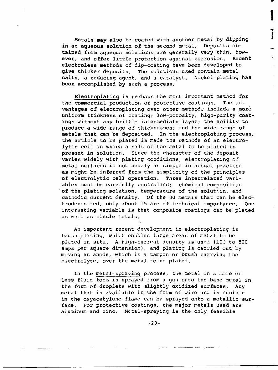
Metals may also be coated with another metal by dippingin an aqueous solution of the second metal. Deposits ob-tained from aqueous solutions are generally very thin, how-ever, and offer little protection against corrosion. Recentelectroless methods of dip-coating have been developed togive thicker deposits. The solutions used contain metalsalts, a reducing agent, and a catalyst. Nickel-plating hasbeen accomplished by such a process.
Electroplating is perhaps the most important method forthe commercial production of protective coatings. The ad-vantages of electroplating over other method--, include a moreuniform thickness of coating; low-porosity, high-purity coat-ings without any brittle intermediate layer; the ability toproduce a wide range of thicknesses; and the wide range ofmetals that can be deposited. In the electroplating process,the article to be plated is made the cathode of an electro-lytic cell in which a salt oZ the metal to be plated ispresent in solution. Since the character of the depositvaries widely with plating conditions, electroplating ofmetal surfaces is not nearly as simple in actual practiceas might be inferred from the simplicity of the principlesof electrolytic cell operation. Three interrelated vari-ables must be carefully controlled: chemical compositionof the plating solution, terperature of the solution, andcathodic current density. Of the 30 metals that can be elec-trodeposited, only about 15 are of technical importance. Oneinteresting variable is that composite coatings can be platedas w21l as single metals.
An important recent development in electroplating isbrush-plating, which enables large areas of metal to beplated in situ. A high-current density is used (100 to 500amps per square dimension), and plating is carried out bymoving an anode, which is a tampon or brush carrying theelectrolyte, over the metal to be plated.
In the metal-spraying pzocess, the metal in a more orless fluid form is sprayed from a gun onto the base metal inthe form of droplets with slightly oxidized surfaces. Anymetal that is available in the form of wire and is fueiblein the oxyacetylene flame can be sprayed onto a metallic sur-face. For protective coatings, the major metals used arealuminum and zinc. Metal-spraying is the only feasible
-29-
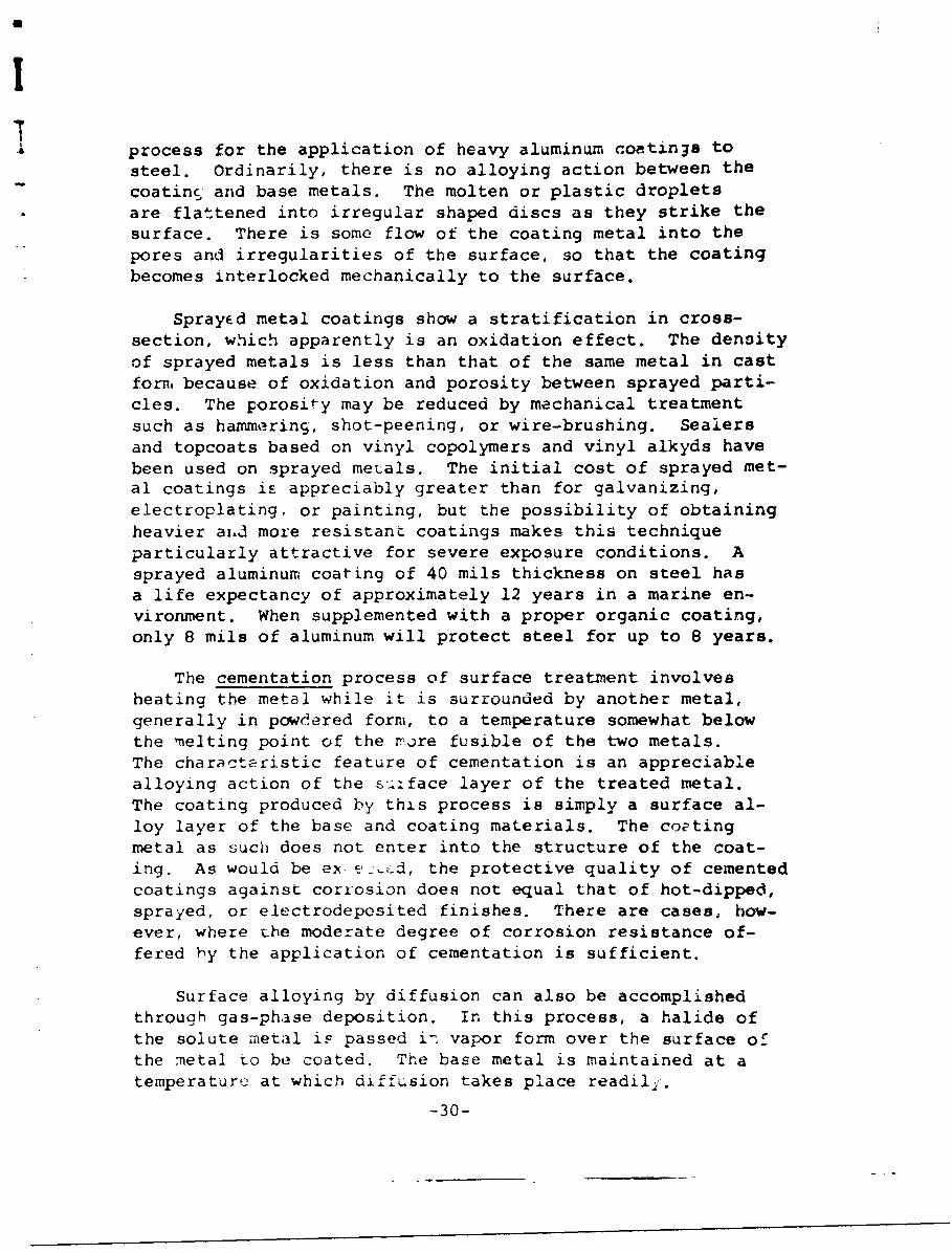
a process for the application of heavy aluminum coatings tosteel. Ordinarily, there is no alloying action between the
coating and base metals. The molten or plastic dropletsare flattened into irregular shaped discs as they strike thesurface. There is some flow of the coating metal into thepores and irregularities of the surface, so that the coatingbecomes interlocked mechanically to the surface.
Sprayed metal coatings show a stratification in cross-section, which apparently is an oxidation effect. The densityof sprayed metals is less than that of the same metal in castform, because of oxidation and porosity between sprayed parti-cles. The porosity may be reduced by mechanical treatmentsuch as hammering, shot-peening, or wire-brushing. Sealersand topcoats based on vinyl copolymers and vinyl alkyds havebeen used on sprayed metals. The initial cost of sprayed met-al coatings is appreciably greater than for galvanizing,electroplating, or painting, but the possibility of obtainingheavier ai.J more resistant coatings makes this techniqueparticularly attractive for severe exposure conditions. Asprayed aluminum coating of 40 mils thickness on steel hasa life expectancy of approximately 12 years in a marine en-vironment. When supplemented with a proper organic coating,only 8 mils of aluminum will protect steel for up to 8 years.
The cementation process of surface treatment involvesheating the metal while it is surrounded by another metal,generally in powdered form, to a temperature somewhat belowthe melting point of the rore fusible of the two metals.The characteristic feature of cementation is an appreciablealloying action of the s-.:face layer of the treated metal.The coating produced by this process is simply a surface al-loy layer of the base and coating materials. The coptingmetal as such does not enter into the structure of the coat-ing. As would be ex • the protective quality of cementedcoatings against corrosion does not equal that of hot-dipped,sprayed, or electrodeposited finishes. There are cases, how-ever, where the moderate degree of corrosion resistance of-fered by the application of cementation is sufficient.
Surface alloying by diffusion can also be accomplishedthrough gas-phase deposition. In this process, a halide ofthe solute mietal iF passed i7 vapor form over the surface orthe metal to be coated. The base metal is maintained at atemperature at which diffusion takes place readil 1 .
-30-

Another process related to cementation is that of at-taching sintered carbides to steel surfaces. Such coatingsare useful in applications where localized wear and corrosionresistance are required. The carbides of tungsten, tantalum,titanium, cobalt, boron, and silicon are among the most im-portant. The carbides are sintered with a powdered metalsuch as cobalt or nickel, then brazed onto steel surfaces.
Coatings produced by condensation of r..metallic vapor maybe grouped according to the source of the vapor as follows:decomposition of chemical compounds of metals, cathode sput-tering, and evaporation of molten metals. In all throe cases,the process involves the use of vacuum equipment and rela-tively high temperatures. Although these coatings are muchcostlier than electroplated coatings, it is possible to ob-tain, by vapor deposition, coatings that cannot be producedin aiy other way.
Metal cladding, the veneering of base metal plate withother metals, has long been practiced as a coating methodThe method most used to produce this configuration is rollbonding, in which the coating metal at the desired th.icknessis rolled onto the base metal at an elevated temperature.Another technique is that of producing a duplex ingot of thetwo metals, then rolling or drawing the ingot into the desiredshape. This process is applicable only for those metals thatdo not differ radically in their rolling characteristics.
Metallic Coating Materials
The choice of a metil1ic coating for marine applicationsis based primarily on the protection it offers againsL cor-rosion of the base structural metal. The entire spectrum ofmetals (listed in the galvanic series in Figure 4) -- -vail-able, with the type of protection depending upon the i-'ia*vepositiors of the base metal and the coating in th, galvanicseries. Sacrificial coating will result if the coating ma-terial is anodic to the base metal, and noble ccasing willresult for coating metals i,,ore cathodic t:an the structuralbase material. Additional considerations in the selectionof a coating for a given base retai in a given environmentinclude resistance to abrasion and feasibility of developingan adequate coating with a reasonably economical p--o-_zs.
-31-
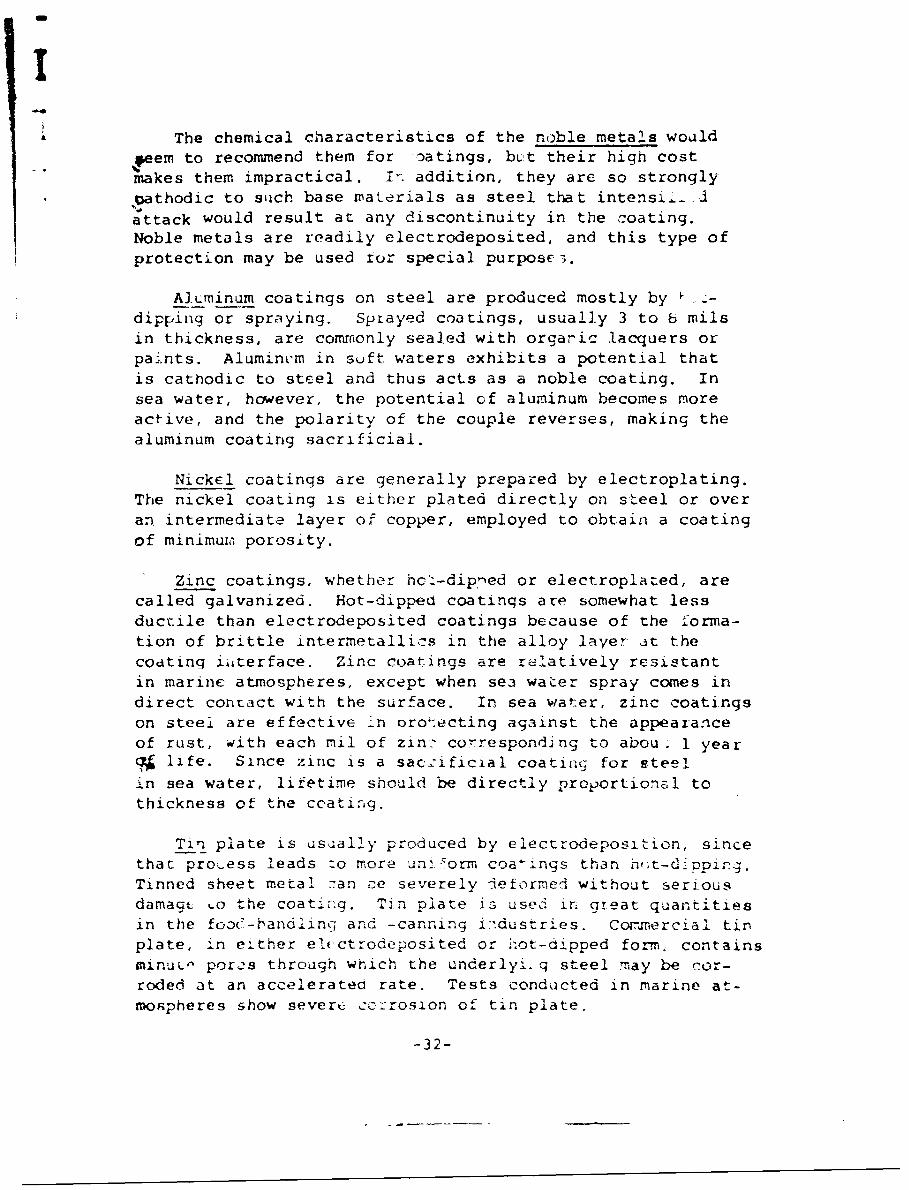
The chemical characteristics of the noble metals would
4,eem to recommend them for oatings, blt their high costmakes them impractical. In. addition, they are so strongly
? athodic to such base materials as steel that intensL-, .
attack would result at any discontinuity in the coating.Noble metals are readily electrodeposited, and this type ofprotection may be used for special purpose;.
AJLminum coatings on steel are produced mostly by -dipping or spraying. Sptayed coatings, usually 3 to b milsin thickness, are commonly sealed with orgaric lacquers orpaints. Alumini'm in suft waters exhibits a potential that
is cathodic to steel and thus acts as a noble coating. Insea water, however, the potential of aluminum becomes moreactive, and the polarity of the couple reverses, making thealuminum coating sacrificial.
Nickel coatings are generally prepared by electroplating.The nickel coating is either plated directly on steel or overan intermediate layer of copper, employed to obtain a coatingof minimuia porosity.
Zinc coatings, whether hcz-dipned or electroplated, arecalled galvanized. Hot-dipped coatinqs are somewhat lessductile than electrodeposited coatings because of the forma-tion of brittle intermetallics in the alloy layer at thecoating iilterface. Zinc coatings are relatively resistantin marine atmospheres, except when se3 water spray comes indirect contact with the surface. In sea water, zinc coatingson steel are effective in orotecting against the appearanceof rust, with each mil of zin- corresponding to abou. 1 yearSlife. Since zinc is a saczificial coating for steel
in sea water, lifetime should be directly proportional tothickness of the coating.
Ti__n plate is usually produced by electrodeposition, sincethat proý_ess leads :o more un. corm coalings than h,.t-dippicg.Tinned sheet metal zan ce severely deformed without seriousdamage -o the coating. Tin plate _s used in great quantitiesin the fooC-bandlinc and -canning i:.dustries. Comnrercial tinplate, in either elcctrodeposited or h'ot-dipped form., containsminuL^ pores through which the underlyi. q steel mnay be cor-roded at an accelerated rate. Tests conducted in marine at-mospheres show severt cc:-rosion of tin plate.
-32-

i
QjMi coatings are produced almost exclusively byelectrodeposition. The difference in potential betweencadmium an~d steel is not as large as the difference betweenzinc and steel, so that the cathodic protection of steel by Ia coating of cadmium falls off more rapidly with size ofcoating defects. Cadmium is more resistant to attack in themarine environment than is zinc, but is more expensive thanzinc.
Chemical ConversionCoat4 inHq % .
A coating formed by chemical or electrochemical modifi-cation of the metal surface, where the nonreactive coatingformed is an integral part of the parent metal, is called achemical conversion coating. These protective coatings pro-vide an insulacing barrier of very low solubility betweenthe metal and its environment. Most of these coatings lendthemselves particularly to impregnation with organic coatings,and it is in this application that the chemical conversioncoatings presently find their greatest use. In some cases,however, -onversiorn coatings are used without further treat- I Iments.
Two techniques are commonly used for forming this type I Iof protective coating: chemical dip, spray, or brush; andelectrolytic methods. in chemical dip reactions, an oxideof the base metal or of a metal ion present in 1The bath isformed on the netal surface. Electrolytic processes dependon an externally applied voltage vo promote the formationof protective films in a Suitable electrolyte.
Phosphating, an example of the chemical dip process, isgenerally used to provide a paint base on steel and zincS.-For most applications, the phosphate coating is not suffi-ciently protective without the addition of an organic coat-inro Another chemical process-chromating--results in en-hanced protection of zinc and cadmium in humid atmospheres.These chcomate conversion coatings are used purely for pro-tection purposes without additional. finishing treatment.Chemical dip methods are also used to develop oxide filmson iron, steel, stainless steel, aluminum, and copper andits alloys. The resulting chemical oxide coatings on stain-less steel, aluminum, and copper provide relatively goodresi~stnce to corrosion, but in the other cases, their pro-tective alue is limited.
-33-
i
The foremost application of the electrolytic process isin the anodizing of aluminum alloys. The anodic oxidationof aluminum and its alloys produces a surface coating withrelatively high resistance to corrosion and abrasion. Ofthe common electrolytes used in anodizing, chromic acid pro-duces the most corrosion-resistant coatings on a given alloy.Sealing this coating with hot water or an alkali dichromateimproves its protective value.
Additional discussions on coatings for the protection ofthe structural element of a bulkhead follow in later sections.Organic and inorganic nonmetallic coatings are discussed inSection IV under "Coatings for Maintenance." Application ofall kinds of coatings under in situ conditions is discussedin Section V under "Coatings for Repair."
-34-
'IiJ
Concrete that is properly proportioned, mixed, andplaced is one of the most durable materials available forshore protection. Service records indicate that qualityconcrete can endure for 50 years with only modest maintenancerequirements.
Cast-In-Place Concrete
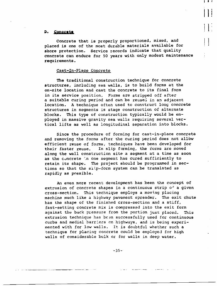
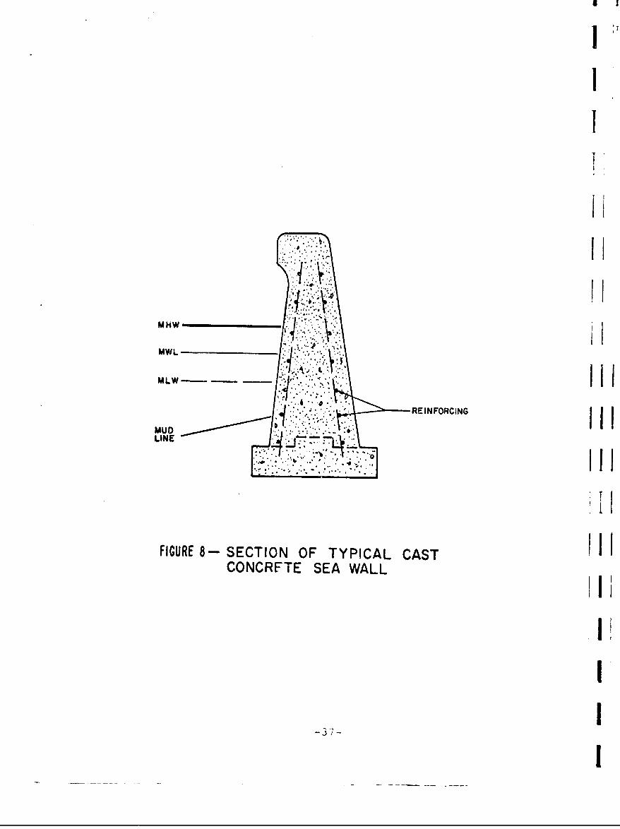
The traditional construction technique for concretestructures, including sea walls, is to build forms at theon-site location and cast the concrete to its final formin its service position. Forms are stripped off aftera suitable curing period and can be reuseci in an adjacentlocation. A technique often used to construct long concretestructures in segments is stage construction of alternateblocks. This type of construction typically would be em-ployed in massive gravity sea walls requiring several ver-tical lifts as well as longitudinal separation into blocks.
Since the procedure of forming for cast-in-place concreteand removing the forms after the curing period does not allbwefficient reuse of forms, techniques have been developed fortheir faster reuse. In slip forming, the forms are movedalong the wall construction site a segment at a time as soonas the concrete n one segment has cured sufficiently toretain its shape. The project should be programmed in sec-tions so that the slip-form system can be translated asrapidly as possible.
An even more recent development has been the concept ofextrusion of concrete shapes in a continuous strip o; a givencross-section. This technique employs a moving placingmachine much like a highway pavement spreader. The exit chutehas the shape of the finished cross-section and a stiff,fast-setting concrete mix is compressed into the exit formagainst the back pressure from the portion just placed. Thisextrusion technique has bc'.n successfully used for continuouscurbs and medial barriers cn highways, and is being experi-mented with for low walls. It is doubtful whether such atechnique for placing concrete could be employed for highwalls of considerable bulk or for walls in deep water.
-35-
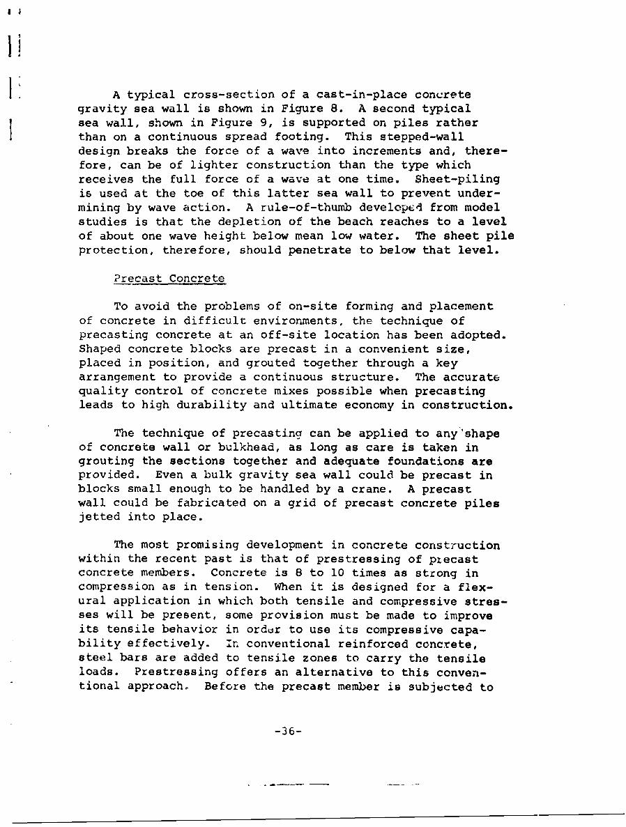
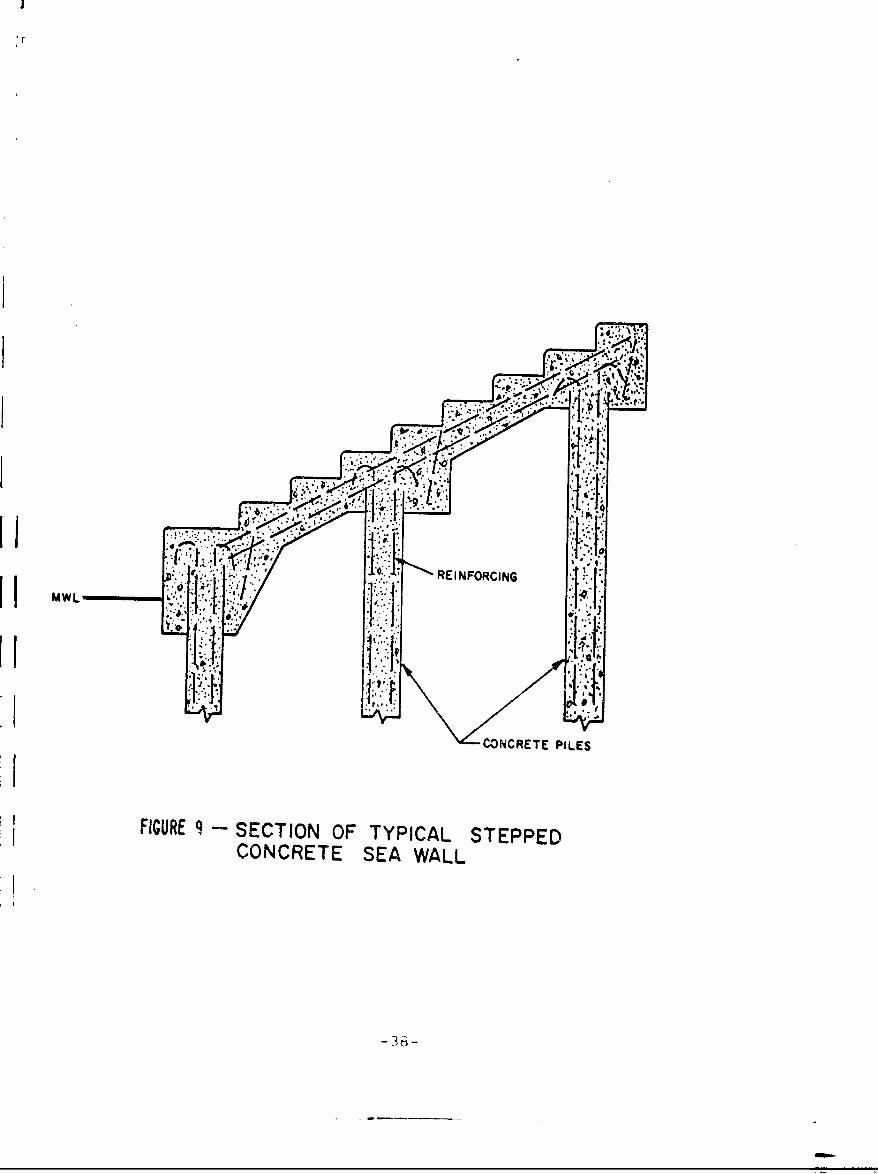
A typical cross-section of a cast-in-place concretegravity sea wall is shown in Figure 8. A second typicalsea wall, shown in Figure 9, is supported on piles ratherthan on a continuous spread footing. This stepped-walldesign breaks the force of a wave into increments and, there-fore, can be of lighter construction than the type whichreceives the full force of a wave at one time. Sheet-pilingis used at the toe of this latter sea wall to prevent under-mining by wave action. A rule-of-thumb developci from modelstudies is that the depletion of the beach reaches to a levelof about one wave height below mean low water. The sheet pileprotection, therefore, should penetrate to below that level.
?recast Concrete
To avoid the problems of on-site forming and placementof concrete in difficult environments, the technique ofprecasting concrete at an off-site location has been adopted.Shaped concrete blocks are precast in a convenient size,placed in position, and grouted together through a keyarrangement to provide a continuous structure. The accuratequality control of concrete mixes possible when precastingleads to high durability and ultimate economy in construction.
T"he technique of precasting can be applied to any shapeof concrete wall or bulkhead, as long as care is taken ingrouting the sections together and adequate foundations areprovided. Even a bulk gravity sea wall could be precast inblocks small enough to be handled by a crane. A precastwall could be fabricated on a grid of precast concrete pilesjetted into place.
The most promising development in concrete constructionwithin the recent past is that of prestressing of ptecastconcrete members. Concrete is 8 to 10 times as strong incompression as in tension. When it is designed for a flex-ural application in which both tensile and compressive stres-ses will be present, some provision must be made to improveits tensile behavior in orddr to use its compressive capa-bility effectively. In conventional reinforced concrete,steel bars are added to tensile zones to carry the tensileloads. Prestressing offers an alternative to this conven-tional approach, Before the precast member is subjected to
-36-
I
1
MHW
MWL
MLW -"-"
M U D. .4 , " " . . •R E I N F O R C I N G
M U D• , "' '' " " "
FIGURE 8- SECTION OF TYPICAL CASTIICONCRFTE SEA WALL
I
I MWLREINFORCING
I!
II
-ACONCRETE PILES
FIGURE 9 - SECTION OF TYPICAL STEPPEDCONCRETE SEA WALL
I
its service loading, the portion which is to carry the ten-sile load is prestressed into compression through the use ofprestressing cables. This compressive stress must then beovercome in service before the member will be subjected to a
tensile stress; thus, its actual capacity to carry an imposedservices load has been enhanced.
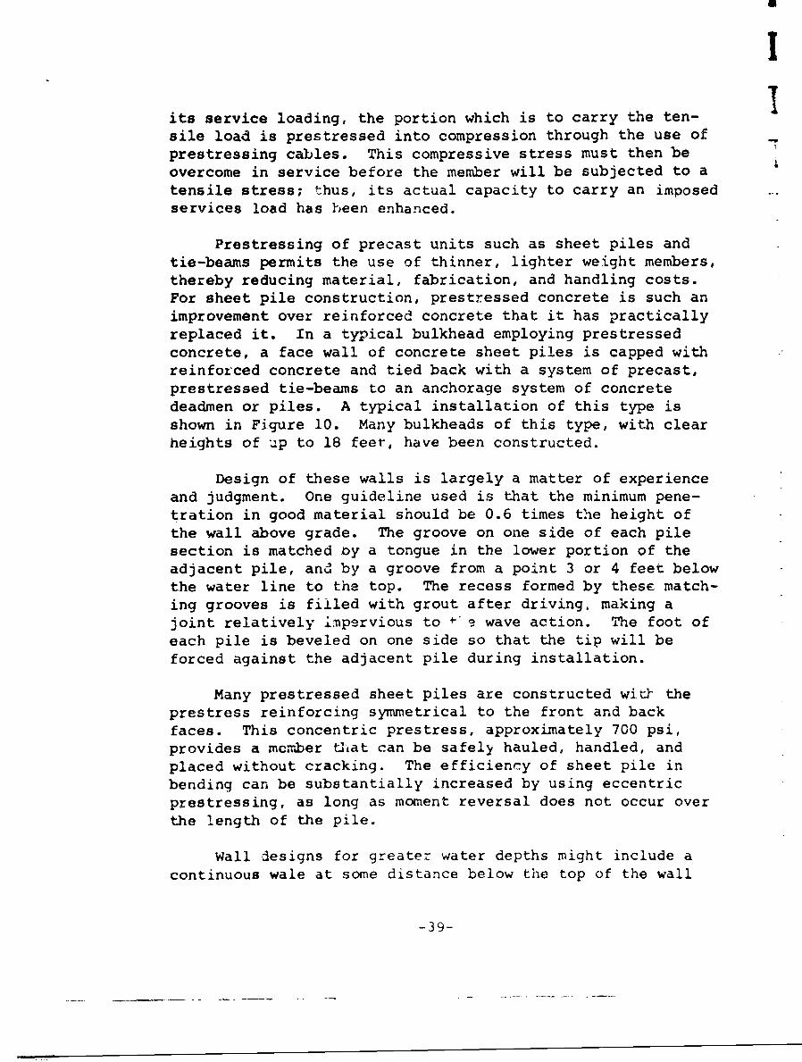
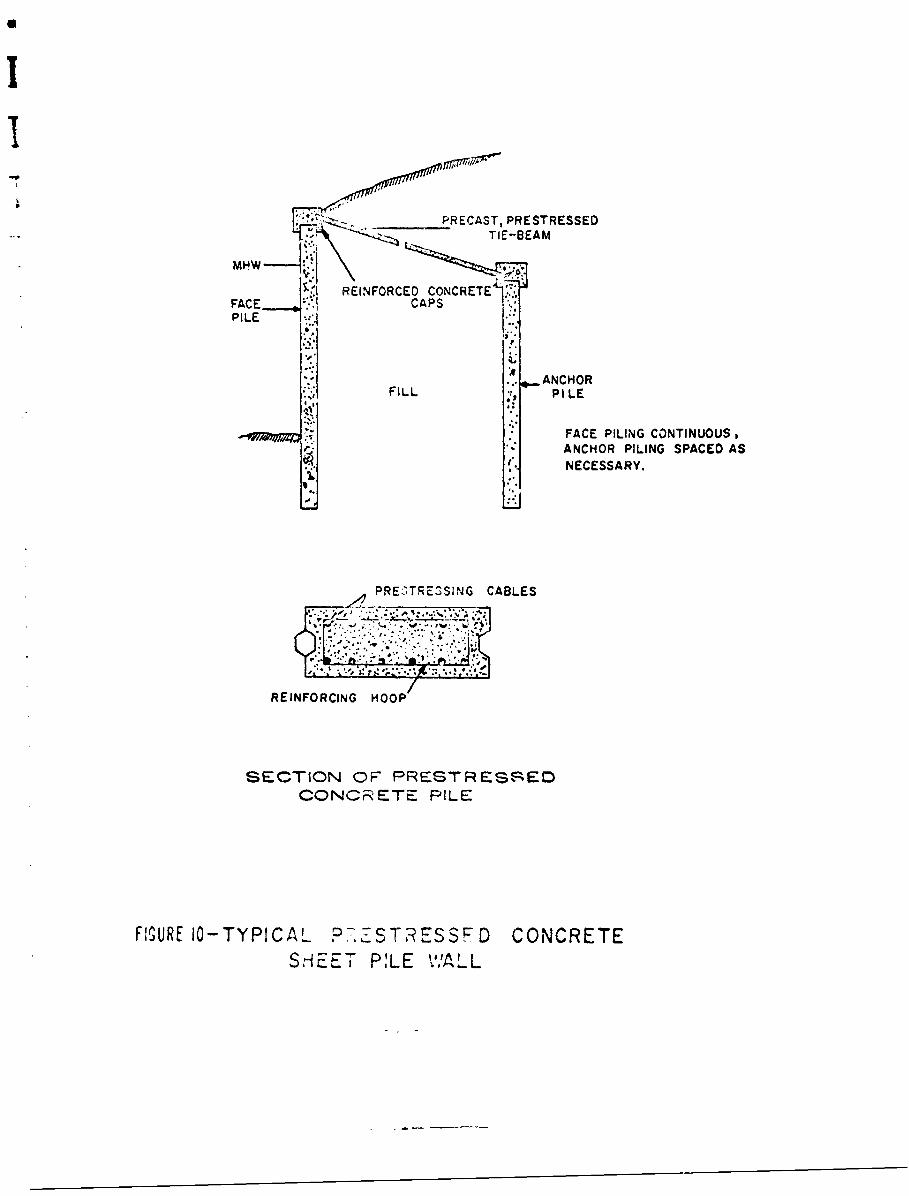
Prestressing of precast units such as sheet piles andtie-beams permits the use of thinner, lighter weight members,thereby reducing material, fabrication, and handling costs.For sheet pile construction, prestressed concrete is such animprovement over reinforced concrete that it has practicallyreplaced it. In a typical bulkhead employing prestressedconcrete, a face wall of concrete sheet piles is capped withreinforced concrete and tied back with a system of precast,prestressed tie-beams to an anchorage system of concretedeadmen or piles. A typical installation of this type isshown in Figure 10. Many bulkheads of this type, with clearheights of up to 18 feet, have been constructed.
Design of these walls is largely a matter of experienceand judgment. One guideline used is that the minimum pene-tration in good material should be 0.6 times the height ofthe wall above grade. The groove on one side of each pilesection is matched ny a tongue in the lower portion of theadjacent pile, and by a groove from a point 3 or 4 feet belowthe water line to the top. The recess formed by these match-ing grooves is filled with grout after driving, making ajoint relatively impervious to • • wave action. The foot ofeach pile is beveled on one side so that the tip will beforced against the adjacent pile during installation.
Many prestressed sheet piles are constructed wit& theprestress reinforcing symmetrical to the front and backfaces. This concentric prestress, approximately 700 psi,provides a member that can be safely hauled, handled, andplaced without cracking. The efficiency of sheet pile inbending can be substantially increased by using eccentricprestressing, as long as moment reversal does not occur overthe length of the pile.
Wall designs for greater water depths might include acontinuous wale at some distance below the top of the wall
-39-
PRECAST, PRESTRESSED
TIE-SEAM
REINFORCED CONCRETE'.*
PILE •
- ANCHOR
FILL PILE
.,.
FACE PILING CONTINUOUS,
ANCHOR PILING SPACED ASNECESSARY.
PRE,'TrE3SiNG CABLES
REINFORCING HOOP
SECTION OF" PRESTRES-,--EIDCONCRETE PILE
FIGURE 10-TYPICAL c),-,.-STRESSFD CONCRETESHEE PILE V/A LL
III
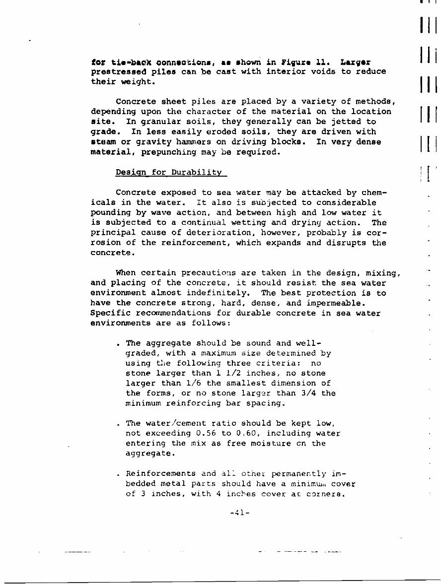
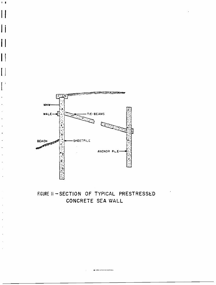
for tie-bacX connbections, an shown in Figure 11. Larger iprestressed piles can be cast with interior voids to reducetheir weight. I
Concrete sheet piles are placed by a variety of methods,depending upon the character of the material on the locationsite. In granular soils, they generally can be jetted tograde. In less easily eroded soils, they are driven withsteam or gravity hammers on driving blocks. In very dense Itmaterial, prepunching may be required.
Design for Durability IConcrete exposed to sea water may be attacked by chem-
icals in the water. It also is subjected to considerablepounding by wave action, and between high and low water itis subjected to a continual wetting and drying action. Theprincipal cause of deterioration, however, probably is cor-rosion of the reinforcement, which expands and disrupts theconcrete.
When certain precautions are taken in the design, mixing,and placing of the concrete, it should resist the sea waterenvironment almost indefinitely. The best protection is tohave the concrete strong, hard, dense, and impermeable.Specific recommendations for durable concrete in sea waterenvironments are as follows:
The aggregate should be sound and well-graded, with a maximum size determined byusing tUe following three criteria: nostone larger than 1 1/2 inches, no stonelarger than 1/6 the smallest dimension ofthe forms, or no stone larger than 3/4 theminimum reinforcing bar spacing.
• The water/cement ratio should be kept low,not exceeding 0.56 to 0.60, including waterentering the mix as free moisture cn theaggregate.
• Reinforcements and all othel permanently im-bedded metal parts should have a minimra, coverof 3 inches, with 4 inches cover at corners.
-41-
IITI
MHWAL"--'--SAM
ANCHOR PI,E"---'l '.
E.%
FIGURE AI-SECTION OF TYPICAL PRESTRESSED
CONCRETE SEA WALL
a
=I
. Air-entrained concrete should be used toprotect from freeze-thaw damage and to aidin workability.
• Placement of concrete in the forms must bedone carefully to prevent segregation. With-in the tidal zone the concrete should beplaced continuously to avoid construction
. After placing, the concrete should be pro-tected from the sea water for at least 4days and should be kept moist for severaldays at a temperature above 500 F.
• Cement used for making concrete exposed tosea water should have low alumina and limecontent.
In addition to mix and placement variables, there arecertain surface treatments which increase the res stance ofconcrete to aggresqive agents. Many such treatments produceonly a shallow surface effect and are suitable only forimproving the resistance of concrete to the less aggressiveagents. Such surface treatments include:
" two coats of magnesium or zinc fluo-
silicate;
" two coats of sodium silicate or water glass;
". two or three coats of boiled linseed oij..(applied hot) ; and
" two or three coats of natural or syntheticresin.
For highly aggressive solktions, the concrete must bephysically prevented from coming in contact with the solu-ti.on. Treatments for this type of exposure include:
two coats of bitumen or coal tar;
-43-
. application of bituminous mastic or asphalt;and
* acid or alkali-resisting bricks or tile laidin special mortar to form a completelyimpervious lining.
These surface treatments for concrete are necessary onlyin excessively aggressive environments. The strong, hard,dense, and impervious concrete described above is sufficientlydurable for normal sea water exposure.
-44-
E. Timber
Timb~er selected for use in shore protection structuresmust meet three types of criteria:
" " adequate structural properties when dam-? orwe t;
" " availability in appropriate sizes and lengthsat reasonable costs; and
" " resistance to deterioration in the shoreenvironment.
Allowable design stresses for timber in vmrious •,oistureconditions are available in Federal Government and J.umberindustry publications. Since timber strength is reduced athigh moisture content, allowable design stresses are generallyless than half those for dried lumber. Strengths of typicalfirs :-d pines currently used in timber shore constructionare about 1/10 those oc structural steels, and moduli areless than 1,000,000 psi. This means that timber structuresfor tUe same loading situation would be considerably moremassive than steel structures. Since the sizes and lengthsof structural timber members are limited by nature, thedimensions and load capacities of shore structures built oftimber are similarly limited.
The principal problem to be considered in connection withtimber shore structures is that of deterioration in the marineenvironment. Damage by marine boring organisms to timber insea water occurs throughout the world. The rapidiiy of theattack depends upon local conditions and the kinds of borerspresent. Current practice indicates that all timber installedin a marine environment should be pressure treated with apreservat: 3 before installation. If the treatment isthorough and penetration deep enough, several preservativeshave been found to be effective in preventing borer attack.
An alternative to using preservative-treaLed nativesoftwoods for timber shore structures is to use tropicalwoods. These are more dense, strong, stiff, and resistantto marine environment than our native woods. Aithough
specific tropical woods are resistant to certain marineborers, no single wood has been found that is resistant toall biological attack. Disadvantages in the use of thesetropical woods include difficulty of fabrication, expense(about twice the cost of native timbers), a tendency toundergo deterioration due tc surface checking when in serv-ice, and an inability to pressure-treat the wood effectivelywith preseivatives. Since the tropical timbers are moree:xpensive than fully treated native woods, their use is onlyjustified in specific critical installations.
Configurations
Timber has been used in several configurations for shoreprotection facilities such as bulkheads and walls. A typicaltimber bulkhead arrangement is shown in Figure 12. This con-figuration is similar to those used when sheet-steel pilingor prestressed concrete sheet piles are used in anchoredbulkheads, but it is limited to lower heights by the sizelimitations and lower design stresses of timber.
Filled timber cribs, such as the one shown in Figure 13,were used extensively in earlier bulkhead construction. Thetop of the timber crib is usually terminated at a low waterlevel and the wall above built of concrete. Firm founda-tions are required for this type of construction; improperfoundations often lead to excescive settlement under theheavy crib construction.
Plywood has been developed to aeal with the anisotrophyand size limitations of natural wood. Marine-grade plywood,bonded with non-water-soluble adhesives, is available whichwithstands immersion in water. Pressure preservative treat-ments are now in use to impregnate plywood through its entirethickness in sheets up to 1 ,nch thick. Plywood sectionsthick enough and large enough for major bulkhead installa-tions, however, are not readily available at this time.
One configuration employed to protect structural timberfrom marine environmental attack is that of sheathing eachmember with a proteot:ve layar. A hardwoo6 timber %,h1ch Iinot readily accept as- v e. n&•y be sheathed with a sap-wood ilyer that is easily impreqnated. In addition, a layer
-'6-

PILE
LISHEETING/STR 4 STRUT
ANCHOROPILE
SECTION PLAN
FIGURE 12 -TYPICAL TIMBER BULKHEAD
WOOD FENDER
RUBBLE BASE SURFACED
.. M I WITH CRUSHED STONE
II>AII
FIGURE 13- TYPICAL TIMBER CRIB WALL
-47-
* .
11
of asphaltic felt is used between the sheathing and thestructural timber to further protect against borer intrusion.
[ Sheathing can be teplaced periodically, if required. Struc-tural timbers can also be sheathed with a thin layer of
-v metal, such as copper or aluminum, which acts as a barrierhetween the marine environment and the timber.
Timber which is properly pressure-treated with a pre-* servative can be made resistant to marine borers in their
underwater environment. This dces not prevent decay due tofungus attack in portions of the structure above the waterline, however. This relative deterioration has led to thedevelopment of so-called "composite construction," in whichtreated timber is used below the water line and a moreresistant material, such as concrete, is used above the waterline. Thus, timber is used underwater where placement ofconcrete is difficult and expensive and concrete is usedabove the water line where it is not subject to -he 4ecayof timber.
Wood Preservation
* -Preserva'ives used for timber may be classified intotwo main groups: oils and oil-borne preservatives andwater-borne preservatives. In the first group are the
* •by-product preservative oils in general use: coal-tar creo-sotes, the creosote-cocl-tar solutions, and the creosote-petroleum solutions. Coal-tar creosote is a distillate ofcoal tar produced by high tcmperature carbonization of bi-tuminous coal. The practice of mixing coal tar with coal-tar creosote has become common for the treatment of timbers.Coal tar is too viscous and insoluble to penetrate woodwell, but its use in combination with coal-tar creosoteserves to reduce the cost of the preservative and to decreasethe tendency of the treated wood to check or split in serv-ice. Petroleum oils are also used as dilutents for coal-tar creosote. When injected into timbers, creosote-petroleum solutions reduce checking to a greater degree thanstraight creosote.
Many oil-solubie chemicals have high toxicity to wood-destroying organisms, but are too costly or unsuited
-48-

physically for use alone as wood preservatives. Penta-chlorophenol and copper napthenate are two commonly usedoil-borne preservatives.
Water is used as a solvent for wood preservatives be-cause of its cheapness and availability. Water-bornepreservatives afford little protection to timbers subject towet environments, however, because of their solubility inwater. Most preservatives of this kind are subject to leach-ing from the treated wood whenever it is in contact withwater or with wet soil. Some newer water-borne preservativesare designed to form compounds of low water solubility asthe water evaporates from the treated wood, When this isaccomplished, the resistance of the preservative to leachingcan be very high. Preservatives of this type generally c(on-tain salts of two or more of the following elements: copper,zinc, chromium, and arsenic. Copperized chromated zincchloride (CCZC) is an example of such a leaching-resistant,water-borne preservative.
Many preservatives of all types are considered propri-etary in that they are patented or sold under trade names.The number of such proprietar" preservatives on the marketis great and constantly chancvng. An analysis of wood pre-
servatives, indicating which _ompounds are efIecti[ve, hasbeen made by the American Wood Preserver's Association.
The selection of the proper methord cF trea%.ent is asimlý-,,rtart as th3 selection of the proper pi-eservative.Pressur:_- processes are generally used to permit imaximum pene-tration of the preservative. '2wo basic methods are employedin lijccting the preservative into the wood: the full-cellprocesc and the empty-cell process. Treatment by the full-cell technique leaves the cells of the wood full of preserv-ative, within the depth of penetration. The empty-cellprocess leaves the cell walls saturated, but no free liquidin the cell cavities. The full-cell process is generallyused in treating material to be used in marine construction.
A relatively new process in which a cr-mbination ofpreservatives is used seems to hold the best promise fortimber preservation in marine environments. A double treat-ment combines an initial copper salt injection with a final
-49-
creosote pressure treatment. It appears that the copper saltpenetraces the zell walls, strengthenii g and hardening them;then the later creosote treatment fills the cell cavities.The full-cell protection of the creosote thus prevents thecopper-salt preservative from being leached away. Earlyresult- from Lest specimens indicate extremely good resistanceto borer attack in timber treated with this double process.
Use of Timber for Shore Protection
Preservation-treated timber has been used extensivelyin the ast for piling, Oucks, and other waterfront structures.However, these gr&aually have been replaced with stronger andmore permanent types of construction. This change hasoccurred because of the great advances made in reinforcedand prestressed concrete design and in the greater "se ofsteel piling. Also, the necessity of designing larger andstronger structures has led to the use of materials ntbAhrLhanI wood. Wood is still one of the cheapest, most flexiblematerials available for small shore facilities, but its lackof permanency in conparison to metals and concrete is limiting.
II
IL

F. Other Ma'-erials
Natural Materials
Sea walls can be constructed of natural materials suchas sand, soil, or stone. These materials can be stabilizedbeyotnd their natural resistance to erosion through theaddition of a cementing medium in the surface layers.
Stone, in the form of block walls or rip-rap, has longbeen used i. shore protecti.on. Block walls are normallyconstructed of massive elements whose stability aQainstwave action is assured, but the blocks may also be bondedtogether by an intermediate layer of mortar. Rip-rap isnormally graded through its cross-section, so that the outersurface has elements large enough to be stable in wavemotion, while the inner material is fine enough to act as afilter against loss of shore materiai. In both block stoneand tip-rap instaliat ons, an adequdte fouLidaiL'.n must bepreparkd to accept the heavy wall. The outward toe of thestone or rip-rap wall must L! buried below the level ofbottom material affected by wave action, perhaps one normalwave height in depth. Either stone blocks or rip-rap canbe used as protective cover for earth embankment walls ratherthan as a structure wall per se.
Soil or sand can be used to form sea walls if adequatelyprotected by stone cover or by cement or chemical stabiliza-tion. Soil-cement protection consists of soil, portlandcement, and water which have been proportioned, mixed, placed,and compacted so that a dense, uniform material results.The principal criterion for selecting appropriate soil isgradation, with the ideal being coarse, sandy, or gravrllysoils containing about 10- to 25-percent of material able topass a No. 200 sieve. Soil-cement slope protection has beensuccessfully achieved by means of both central-plant andmixed-in-place procedures. The protecting material is placedthrough a mechanical spreader and compacted by means ofheavy rollers.
Asbestos-Cement Bulkhcad Sheets
Coirugated asbestos-cement sheet materials are composedof a combination of graded Iong asbestos fibers and special
-51-
0
f
types of poiland cement. The types of portland cement used
have high sea water and sulfate resistance; coating thefibers with this cement gives a strong, lightweight material."The coated fibers are aligned in a co--planar position in thesheet during formztion. The rapid high-pressure expulsionof water in the hydraulic forming process results in a pre-"stressed sheet. This slight compressive prestress, plus thegeometry of the corrugations, provides maximum resistancei:o bending. Corrugated asbestos-cement bulkhead sheets are"jetted into place, then capped with a reinforced concretecap which is in turn anchired back to a deadman with steelbars. Present asbestos-cement sheets are of such limitedthickness and length that they cannot be used safely forshore lines facing the open sea where wave action could besubstantial. For low-rise bulkheads in sheltered locations,however, even the present materials provide corrosion-resist-ant, economical insLd"Iations.
M-lular Brick or Block Panels
Standard masonry construction could be used for seawalls, but the standard mortar would crack anI lose strengthin the marine atmosphere. A recent development in mortarsis a latex additive that imparts fast set, low shrinkage,early strength, and strength retention after curing to themixture. This latex-additive mortar it presently being usedto n.:fabricate brick panels at ground level and then groutt'aem in placc. This development may have a possible appli-cation in sea wall construction. Although regular cementand concrete lose ;trength "cn placed in uater after havLngbeen cured in relativeiy dry conditions, the latex-additivemortar retains its orioinai. strength under these conditions.A sea wall built of masonry units would have the advirntagesof modular construction, i.e., spe:ial brlcks could be usedin the high wear zones and replacement of damaged or wornportions of the wall would be relatively easy.
I
I'
-52-
IV. MAINTENANCE AATERIALS AND ECHNIQZtMS
Sea water is a corrosive medium, and its corrosiveeffectiveness may be enhanced by local additions of contami-nants or biclogical agents. Tidal action causes alternate
I wetting and drying that is detrimental to certain materialsfrom which the bulkheads may be constructed. Splash fromwave action can be damaging since the combination of moisturewith oxygen enhances ccrrosion. The rate of corrosion is alsoaffected by the temperature and relative acidity of the seawater. The increased oxygen content in the water near thesurface, developed through wave action, results in the for-mation of an electrolytic cell, which accelerates corrosiona small distance below the water level in metal bulkheads.The portion of the bulkhead near the sea bottom is subjectedto erooion as solid matter is transported along its length.The design of the bulkhead, including the selection of ma-terials for its construction, must minimize the detrimentaleffects of this hostile environment.
In addition to careful design and selection of materials
in the initial installation of a bulkhead, maintenance isdesirable to retard deterioratio.s. Maintenance refers tothat continual or periodic activity applied to keep the bulk-head from deteriorating in its service environmant, or toslow its rate of deteriorat.icn. The followin" sections de-scribe the major main;,enance techniques and mat-rials avail-able for application to steel bujkneads in marine environments.
A. CCt-odic Protection
Corrosion of metal bulkheads in aqueous environmentsis primarily electrochem'ical ir nature and is C-3e to a cur-rent passing from anodic ar-as of the metal into t.he electro-lyte and returnirz to the metal at cathodic areas. This typeof corrosion can be largely overcome by impressin. a counter-
iicurrent cn the tret-il in aa•- amoeu ;n t s ufficient to n,. itralizethe naturally de-.eloped electric currents. Cathhc. ic protec-
tion serves this preventive maintenance functit,-.
I
-53-
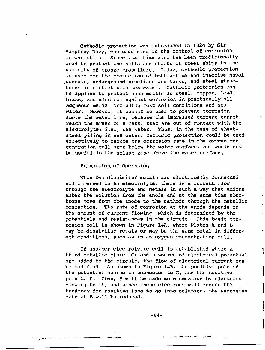
Cathodic protection was introduced in 1824 by SirHumphrey Davy, who used zinc in the control of corrosionon war ships. Since that time zinc has been traditionallyused to protect the hulls and shafts of steel ships in thevicinity of bronze propellers. Today, cathodic protectionis used for the protection of both active and inactive navalvessels, underground pipelines and tanks, and steel struc-tures in contact with sea water. Cathodic protection canbe applied to protect such metals as steel, copper, lead,brass, and aluminum against corrosion in practically allacqueous media, including most soil conditions and seawater. However, it cannot be used to prevent corrosionabove the water line, because the impressed current cannotreach the areas of a metal that are out of contact with theelectrolyte; i.e., sea water. Thus, in the case of sheet-steel piling in sea water, cathodic protection could be usedeffectively to reduce the corrosion rate in the oxygen con-centration cell area below the water surface, but would notbe useful in the splash zone above the water surface.
Principles of Operation
When two dissimilar metals are electrically connectedand immersed in an electrolyte, there is a current flowthrough the electrolyte and metals in such a way that anionsenter the solution from the anode and at the same time elec-trons move from the anode to the cathode through the metallicconnection. The rate of corrosion at the anode depends ont••_ amount of current flowing, which is determined by thepotentials and resistances in the circuit. This basic cor-rosion cell is shown in Figure 14A, where Plates A and Bmay be dissimilar metals or may be the same metal in differ-ent conditions, such as in an oxygen concentration cell.
If another electrolytic cell is established where athird metallic plate (C) and a source of electrical potentialare added to the circuit, the flow of electrical current canbe modified. As shown in Figure 14B, the positive pole ofthe potential source is connected to C, and the negativepole to E. Then, B will be made more negative by electronsflowing to it, and since these electrons will reduce thetendency for positive ions to go into solution, the corrosion Irate at B will be reduced.
-54-
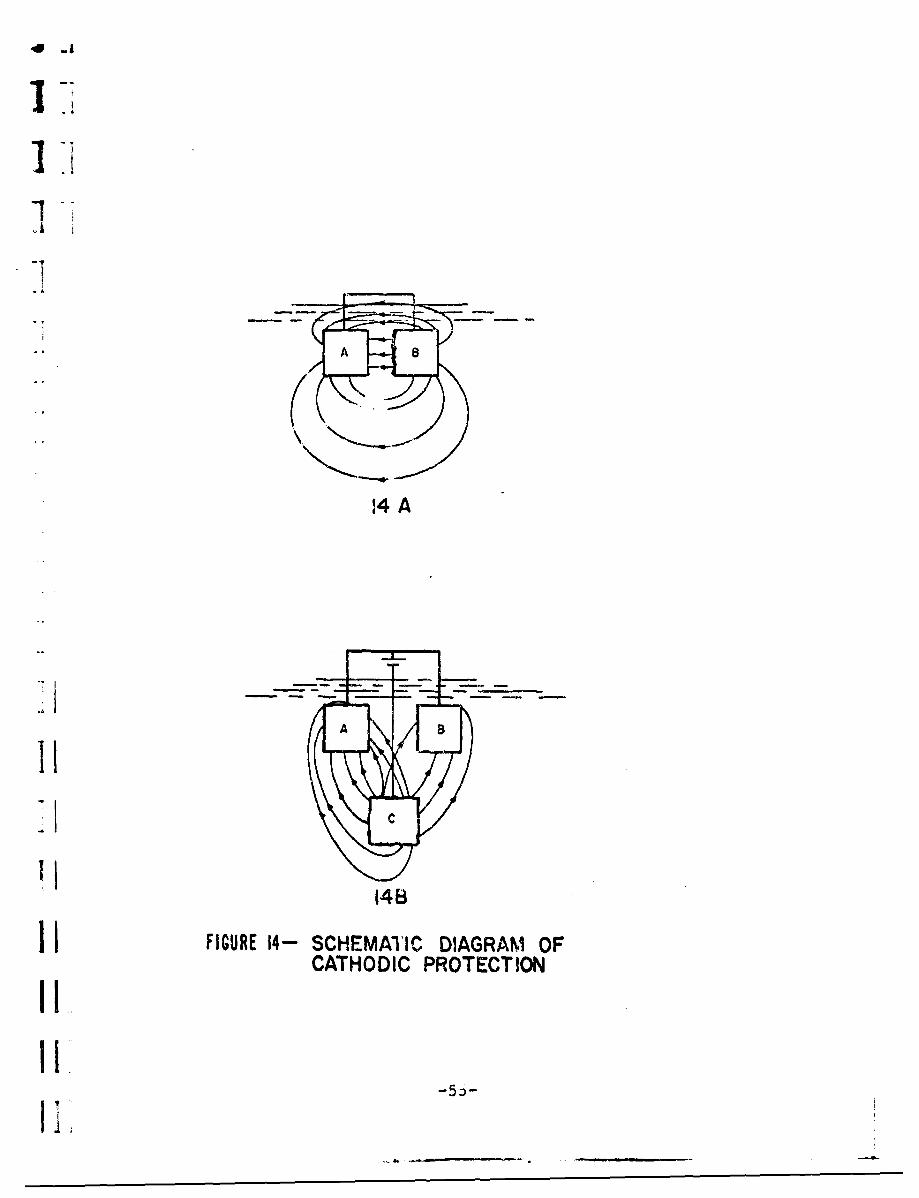
41 A
v-i
14II14BI I FIGURE 14- SCHEMATIC DIAGRAM OF
CATHODIC PROTECTION
II-0
II -o
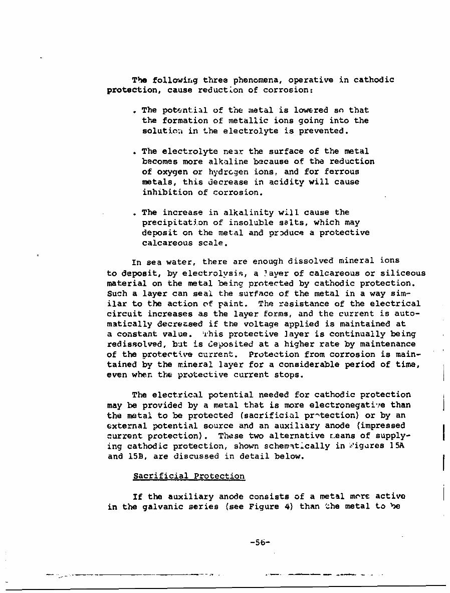
The follroirng three phenomena, operative in cathodicprotection, cause reduction of corrosion:
. The pot'-ntial of the metal is lowered so thatthe formation of metallic ions going into thesolutic;a in the electrolyte is prevented.
& The electrolyte near the surface of the metalbecomes more alkaline because of the reductionof oxygen or hydrogen ions, and for ferrousmetals, this decrease in acidity will causeinhibition of corrosion.
0 The increase in alkalinity w1il cause theprecipitation of insoluble salts, which maydeposit on the metal and produce a protectivecalcareous scale.
In sea water, there are enough dissolved mineral ionsto deposit, by electrolysis, a layer of calcareous or siliceousmaterial on the metal being protected by cathodic protection.Such a layer can seal the surface of the metal in a way sim-ilar to the action of paint. The resistance of the electricalcircuit increases as the layer forms, and the current is auto-matically decreased if the voltage applied is maintained ata constant value. whis protective layer is continually beingredissolved, but is Ceposited at a higher rate by maintenanceof the orotective current. Protection from corrosion is main-tained by the mineral layer for a considerable period of time,even when the protective current stops.
The electrical potential needed for cathodic protectionmay be provided by a metal that is more electronegative thanthe metal to be protected (sacrificial pr-tection) or by anexternal potential source and an auxiliary anode (impressedcurrent protection). These two alternative r..eans of supply-ing cathodic protection, shown schemritically in i.'igares 15Aand 15B, are discussed in detail below.
Sacrificial Protection
If the auxiliary anode consists of a metal more activein the galvanic series (see Figure 4) than the metal to be
-56-
_T
- ELECTROLYTEý4(moi st soil)
ELECTROLYTE-
ANDE ANODE(+W* = - - (ognuiumzince.to,)
IICURRENT FLOWZ 'ýTETHROUGH4 ELECTROLYTE
1 FIGURE I5A- CATHODIC PROTECTION USING SACRIFICIALANODE
-57-
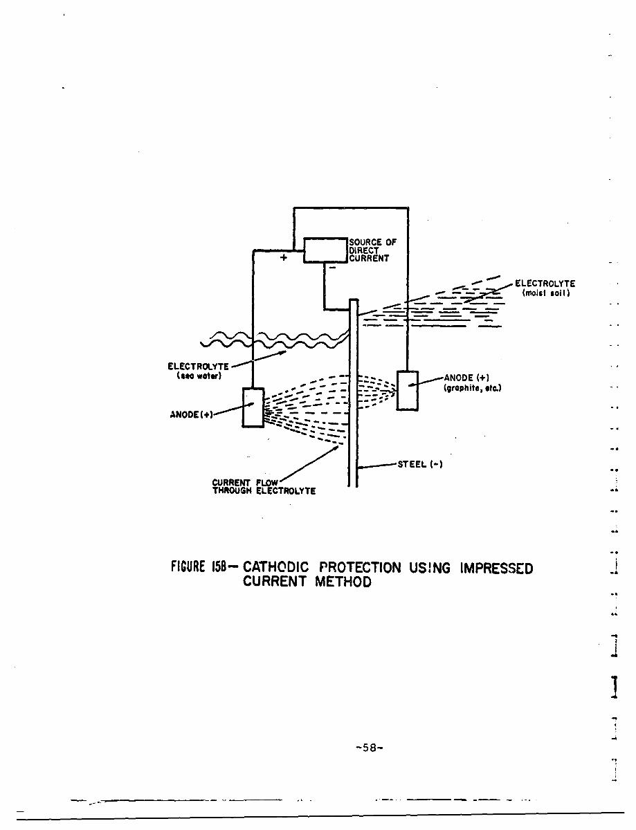
SOURCE OFDIRECT
+ CURRENT
. ELECTROLYTE_ •'-- ~ (moist Wol)
ELECTROLYTE(mo waetr) - z . ANODE W+
(graphite, *tc.)
ANODEM 1+)
-STEEL 1-
CURRENT FLOWTHROUGH ELECTROLYTE
me
FIGURE 15B- CATHODIC PROTECTION USING IMPRESSEDCURRENT METHOD
-58-
protected, a galvanic cell is 6et up in which the auxiliaryanode makes all parts of the metal to be protected cathodic.The earliest experiments on cathodic protection were per-formed with zinc anodes that were electrcically connected tocopper plates and immersed in sea water. In the galvanic
* cell formed in this way, the zinc was the anode and corroded,while the copper wa:3 the cathode. When sufficient currentflowed, the copper became cathodically protected. The zinccorroded to provide the necessary current and, thus, wascalled a sacrificial anode. This method of obtaining cathodicprotection can be used with other combinations of metals aslong as the electrical parameters are such that sufficientcurrent can kg generated to bring about the desired cathodicprotection. Faraday, for example, showed that when zinc andsteel were in electrical contact in sea water, the steel didnot corrode.
Sacrificial metals used for cathodic protection aremagnesium, zinc, aluminum, and alloys of these three metals.Magnesium is most widely used because its high current yieldgives maximum current distribution. The addition of aluminumto magnesium reduces self-corrosion, but minor alloying ele-ments such as copper, nickel, and iron can sirnificantly in-crease the self-corrosion and thus decrease ..e efficiencyof magnesium as a sacrificial anode. In zinc anodes, "imruri-ties must be restricted to very low limits to avoid the form&-
"" tion of insulating films which may rapidly reduce currentoutput. Iron impurities are particularly harmful, and shouldbe limited to 0.0015 percent maximum. Zinc of 99.99 percentpurity is recommended for use as sacrifical anodes. Since
-. pure aluminum develops an oxide film which inhibits its ac-tivity as an anode, it is necessary to alloy the aiuminum tomaintain an effectively high potential. Alloys suitable for
-. anodes include an aluminum/zinc alloy which acts as a lowdriving voltage anode and an aluminum/tin alloy which actsas a medium driving voltage anode.
Sacrificial anodes serve essentially as sources ofportable electrical energy. They are particularly usefulwhen electric power is not readily or economically available.The potential differences between sacrificial anodes and pro-tected cathodes are generally low, so that only limited di-mensions of structure can be protected by each anode This
S~-39-
I
low voltage is sometimes an advantage o,,er impressed voltages,however, in that the dangers of overprotectior of some por-tions of the system and of stray-current damage to adjoiningmetal structures are reduced.
Sacrificial anodes are usually cast, and are available 1in a great range of shapes and sizes, from 5 Lo zOO pounds.Current output is related to composition, surface area andshape, while the lifetime of the anode depends on the ratioof surface area to weight and the current demands of the par-ticular installation. With these factors in mind, an anodecan be designed so that the initial current yield is high 1to assist in polarization, while it later falls off to thatrequired to maintain polarization. Such high initial outputcan be achieved, for example, by the use of finned anodes.When the fins have wasted away, the resultant fall in outputcurrent leads to a decreased rate of anode consumption. Therate of consumption of magnesium alloy anodes is about 17 to20 pounds per ampere year. A 50-pound magnesium anode forsea water use might typically be designed for a 2-year life-time.
The advantages and disadvantages of the sacrificialanode system of. cathodic protection can be summarized asfollows:z
A~vantages:
" Sacrificial anode protection can be usedwhere there is no available power source.
"• No initial investment in power equipmentis required.
" The system is relatively foolproof, andrequires little supervision (e.g., currentcannot be applied in the wrong direction,thus producing corrosion rather than pro-tectior));
" Installation is simple.
" The anode leads are cathodically protected.
-60-

I ] . Disadvantages:
. The current available depends on anodearea, which may have to be substantialfor large structures.
. The cost of Lhe electrical energy producedis considerably higher than for generator
l I produced energy.
For large structures, the high currentflow requires large size leads to keepresistance losses low.
Impressed Current Protection
This type of cathodic protection requires an externaljj source of direct current and an auxiliary electrode locatedsome distance away from the structure to be protected. Thedirect current source is arranged with its positive terminalconnected to the auxiliary electrode, and its negative termi-nal connected to the structure to be protected. Then, thecurrent flows from the electrode through the electrolyte to
II I the structure.
While sacrificial anodes were limited by their drivingvoltage and had to be engineered to suit this limitation, im-pressed current engineering is freed of this limitation. The*applied voltage is not critical, but need only be sufficientto supply an adequate current density to all parts of theprotected structure. To protect a large structure with sacri-ficial anodes, a large number of anodes would be distributedalong the structure, involving considerable installationwork. With impressed current protection, such a structurecould be protected with a much smaller number of anodes,each fed with a greater current.
The source of current is usually a rectifier supplyinglow-voltage direct current of several amperes. Motor gener-ators have been used to transform alternating current to the
required direct current, but maintenance has proven to betroublesom. Windmill generators have been used in areas with
-61-
dependable prevailing winds.
If a structure is protected with a small number of elec-trodes, certain parts of the structure may be overprotectedin achieving the complete protection of all other parts.Moderate overprotection of steel structures usually does noharm, except for some waste of electric power and increasedconsumption of auxiliary anodes. In extreme cases of over-protection of steel, however, additional disadvantages canresult if hydrogen is qenerated at the protected structurein large amounts. Such excessive hydrogen generation cancause blistering of organic coatings, and hydrogen embrittle-ment of the steel.
Control of the cathodi- protection current can beachieved simply by varying the output from the direct currentsource. Thus, the output of the cathodic protection systemcan be balanced to that required by the structure, a techniquewhich cannot readily be applied with sacrificial anodes. Atthe time of initial 4nstallation, adjustment of individualanode outputs can be made to balance the protection. Subse-quently, the entire cathodic protection network can be ad-justed to meet the demand. This dynamic control of the sys-tem can be operated either manually or automatically.
Since the current is being supplied from an externals9-urce, the anode material used in impressed current systemsrequires different properties than those of the sacrificialmetals. The resistance of the anode must not change greatlyeither by consumption or by polarization. The anode systemshould be relatively permanent, having a low overall lifecost. The cost of the anode will depend upon required life-time, the most economical driving voltage, anO the possibilityand ease of anode replacement.
The pioneers of impressed current cathodic protectionused scr'• .- on and steel as consumable electrodes. Suchanodes i en particularly successful in sea water, wherethe degree of polarization is small. Pure aluminum has alsobeen used successfully as a consumable electrode in sea water.Usually, however, where economic advantage leads to the selec-tion of an impressed current system rather than sacrificial
-62-
Ill anode protection, the most economical impressed currentelectrode will be a permaanent anode.
The first permanent anodes were made from graphite andcarbon. Graphite costs more than scrap iron, both initiallyand in subsequent higher electrical power costs. It is alsomore fragile than scrap iron, so must be installed with greatercare. However, graphite anodes are consumed at about one-tenththe rate for scrap iron. 3ilicon-iron anodes, containing 1i%Si and 3% Mo, azt i useJ as permanent electrodes for im-pressed current protection. They can be used at higher currentdensities than carbon, while having a comparable economic life.Silicon-iron anodes have been used extensively in marinecathodic protection installations in the past, but are beinglargely superseded by platinized titanium. In the latterarrangement, a thin film of platinum is plated cnto a titaniumsupport. Platinum, with a 10-percent addition of rhodium orpalladium, is a tr•,ly permanent anode in sea water. Titaniumis heavily anodized in most electrolytes and becomes self-insulating through the formation of a film. This film preventsfurther corrosion so that when the platinum cladding acts asan anode, the titanium carrier remains an insulated support.Since the laver of platinum on the anode needs to be only afew microns thick, this arrangement is much more economicalthan the use of solid platinum anodes.
Cathodic protection rectifiers are generally oil-immersedto provide long, trouble-free service. Air-cooled units areless expensive on initial installation, however, and may beused if adequate maintenance is available. The rectifiers,which are usually selenium or silicon types, are mounted onpoles or other suitable platforms.
For sacrificial anodes where the connection cable iscathodically protected, cable insulation is not important.For impressed current systems, however, high quality insulatedcable is required. Polyethylene-insulated PVC sheathed cableshave been found generally suitable for this purpose.
The amount of cur'rent required to protect a surfacedepends upon coatings used, the nature of the electrolyte,'I and the amount of oxygen concentration. The applied currentdensity must always exceed the current density equivalent to
--63 -
I

4
4
the measured corrosion rate in the same environment. Thus,the greater the potential corrosion rate, the higher mustbe the impressed current density for pkotection. If the pro-tective current induces precipitation of an inorganic scaleon the cathode surface, the total required current falls offas the scale builds up. rhe precise requirements for currentdensity for complete cathodic protection can best be deter-mined by potential measurements taken directly at the protectedstructure in its service environment. Approximate values ofcurrent requirements for steel in sea water are 3 to 5 milliam-peres (ma.) per square foot for painted steel, 10 ma. forbare steel, and 20 to 150 ma. in high velocity, oxygen-richwater.
The advantages and disadvantages of impressed currentcathodic protection systems may be summarized as follows:
" Advantages:
" the protecting current can be varied toany desirable amount to optimize opera-tion as a function of time; and
"* leads need net be large, since resistancelosses can be o-iercome by increasingapplied voltage.
"Disadvantages:
continuous direct current electricalpower must be available;
more technical supervision is required(e.g., connections must be made so thatthe current flows in the right direction);and
the anode leads must be well insulatedand waterproofed in order to avoid theirpreferential consumption.
The general dividing line between sacrificial and im-pressed current systems for cathodic protection appears to
-64-
7
Sbe the size of the installation. Sacrificial anodes areimpractical for a large installation because of the numberof anodes requirgd, and the frequency with which they mustbe replaced. Conversely, impressed current systems are im-practical for small structures because of high installation"costs. For the normal sheet-steel piling installation, then,an impressed current system would be indicated.
Application to Sheet-Steel Piling
The sheet-steel piling used in wharf and bulkhead con-struction can be cathodically protected against corrosionby impressed current techniques. Since the piling is usuallycorrugated or otherwise offset periodically, the area of themetal to be protected is greater than the ffrontal area. Inaddition to the current densiuy required to protect the sea-ward side of the piling, a lesser amount will be used to pro-tect the side which is adjacent to the backfill soil. Ifthe piling had been treated with a bituminous paint coatingbefore driving, the structure might require 1 to 2 ma. persquare foot for protection on the sea water side and an ad-ditional ½ to 1 ma. on the land side. In this situation,100 yards of piling 40 feet deep would require a currentof about 36 amps. The steady-state current demand could bereduced by an initial polarization, say 150 amps for ten days,bringing a reduction of 50 to 70 percent in the current re-quired to maintain protection on the sea water side. Sincethe polarization treatment would not be as effective on theland side, the overall current density requirement might bereduced by 40 to 50 percent of the nonpolarized requirements.
In many cathodically protected structures, particularlythose in high-resistivity soils, calculations are maee forpotential spread so that anodes may be appropriately posi-tioned. When the electrolyte is sea water or a similar low-resistance electrolyte, however, the location of anodes isof secondary importance.
Combined Use With Coatings
It is common practice to use an insulating coating on-. structures in conjunction with the application of cathodic
protection using either impressed current or sacrificial
-65-
I
annodes. In cases where the distribution of current is notideal, various coatings may be used to redistribute the cur-rent aslectively. The insulating coating need not be pore-free, since the protective current flows preferentially toexposed metal areas.
The ptincipal value of coatings on cathodically pro-tected structures is to interpose electrical resistance betweenthe electrolyte and the metal, and to keep the metal dry.A strongly adherent coating of high resistance will preventcorrosion by suppressing the corrosion currents. Resistanceof new coatings can range from a few thousand to several mil-lion ohms per square foot. A coating that admits water willnot maintain high resistance. The principal value of cathodicprctection with a good coating is to prevent corrosion andpitting at the breaks in the coating. Since less currentflows in a coated system, the cost of electrical energy isdecreased.
Stray Currents and Interference
Stray currents may be produced during the operation ofcethodic protection, and may traverse buried pipes or cablesor other structures which are not being cathodically protected.This stray current interference can accelerate 'he corrosionon such nearby metallic structures. There are two mechanismsby which such corrosion occurs: the current may flow in themetal, causing it to have various potentials, or it may flowin the electrolyte, thus developing a potential gradient. Ineither case, a variation in potential will cause an electro-lytic cell to be formed.
Economic Considerations
The guarantee of corrosion control makes it possibleto specify thinner sections, avoiding any extra thickness asa safety factor against corrosion. This saving alone canpay for a major part of the capital equipment and installa-tion costs of cathodic protection.
Corrosion costs can be estimated and comparisons canbe drawn to economically evaluate protection. Where themethods of protecting the metals are more expensive than
-66-
* 4
1 ] the detrimental effects of corrosion, then protection cannotbe justified. In situations where replaceme~nt of the metalcomponent requires dismantling cf additional superstructuresor the necessity of periodic shutdowns for repairs, it ismore economical to use preventive protection.
IIUse of coating in conjunction with cathodic protectionmust similarly be justified on economic grounds. The costof the coating must be balanced against the reduced cost ofthe cathodic protection in the electrolytic zone. Variouscombinations of coatings and required amounts of cathodicprotection current can be compared to determine the optimumprotection arrangement with respect to cost over the lifetimeof the installation.
111! 1
-67-

It
II
B. Coatings for Maintenance IIMetal coatings were discussed previously in the slc- I I
tion concerned with initial installation techniques. Sinceit is assumed that the organic coatings are less permanentand would have to be periodically maintained during the IIlifetime of the protected structure, the discussion of thistype of coating has been included with maintenance tech-niques.
Application Conditions
Whenever possible, organic coating application shouldbe carried out under dry conditions. Surface preparationshould be carried out in a manner similar to that describedabove for metallic coatings, so that all rust, mill scale,grease, and dirt are removed. After preparation of the sur-face, it is left in a condition highly susceptible to corro-sion, so that application of the coating should follow imne-diately.
It is poor practice to apply organic coatings to sur-faces covered with a film of moisture. Such a film affectsadhesion and can reduce the lifetime of the coating. Sincemoisture also prolongs drying time, dust and dirt can be-come attached to the coated surface. In marine environments,these difficulties are increased by the saline atmosphere.Salts trapped beneath a coating lead to the rapid formationof voluminous rust, which forces the coating outwards andfinally disrupts it.
Organic Coatings
To protect against corrosion, a good organic coatingshould:
" provide a good vapor barrier, as impermeable aspossible to water and oxygen;
.6
"* inhibit corrosion, so that any water reachingthe metal surface has less effect; and
" provide long life at low cost.
-68-
-a-----
IIl
IIIIn paints, the first criterion is met by application ofmultiple coats, each of which seals up pores and other de-
SI 1 fects in previous layers. The diffusion path through thepaint film is also increased by incorporating pigments,particularly those having the shape of flakes, oriented
SI parallel to the metal surface. The second criterion can bemet by incorporating, into the prime coat, pigments thatare effective corrosion inhibitors when dissolved in water.The third criterion must be measured in terms of perform-ance in the service environment. Both material cost andlabor must be considered in evaluating the cost-lifetime re-lationship.
Paints
A paint is basically an insoluble pigment dispersed inan organic fluid medium. The organic medium is modified bydryers and thinners, which are volatile compounds added tocontrol viscosity during manufacture and application. Be-fore a paint is formulated, it is necessary to know the cir-cumstances under which it will be applied and the subsequentexposure conditions. These conditions and the propertiesrequired in service will dictate the choice of binding me-dium, which, in turn, will limit the choice of solvents.The quantity of solvent used will depend on the intrinsicviscosity of the binder anc the paint viscosity appropriateto the method of application (brushing, spraying, or dip-ping).
Since a single paint rarely has all of the requiredproperties, a system of paints is normally used. A paintsystem usually consists of a primer, undercoats, and a finalcoat. The primer is selected for adhesion and prot•&tion ofthe metal substrate. Undercoats normally have a high pig-menc content for barrier formation and a low glous. Thefinal coat is chosen for protection and finish. In marineapplications where marine organisms may grow on painted Sur-faces, an additional coat of an antifouling paint is applied.
The most important component of a paint is the bindingmedium or vehicle, which determines the physical and chemi-cal properties of the paint. The general characteristicsof various binding media follow:
-69-".4
* Drying oils. On exposure to the air, theseoils oxidize and polymerize to solids. Lin-seed oil is the most important of the dry-ing oils and is the only one commonly used inits natural state. Its main use is in corro-siun-inhibiting primers. Paints based on rawlinseed oil have the disadvantages of slowdrying, lack of gloss, and insufficient flowto level out brush marks. Improvement ofthe properties of the raw drying oil resultsfrom one of three kinds of heat treatment:boiled oils (heated with a dryer), stand oils(heated with the exclusion of air to bringabout a degree of polymerization), and blownoils (heated without a dryer but with airblown through to produce a material rich inhydroxyl polar groups).
Oil varnishes. All varnishes and paint me-dia prepared from drying oils and natural orsynthetic resins are classified as oil varn-ishes. The introduction of such resins asrosin, gum congo, rosin-modified phenolics,and oil-soluble 100-percent phenolics re-sults in improved drying and film properties.Oil varnishes can perform excellently asprimers for clean or pretreated ferrous metalsurfaces. However, they do not have as muchtolerance for wire-brushed rusted surfacesas d3 oil-based primes.
. Alkyd resins. These polyesters of moderatemolecular weight are perhaps more widely usedthan any other type of binder. The diversemembers of this family can be divided accord-ing to their use: air drying (alkyds capableof air'drying do so through oxidation of thedrying oils they contain), stoving (based ondrying or semi-drying oils, where the oxida-tive properties are of less importance), andplasticizing (those alkyds used in conjunctionwith a larger percentage of harder resin).
-70-
III
*Amino resins. The two aminor~ esins in com-mon use, urea formaldehyde and melamine form-'aldehyde, are used as components in stovingfinishes.
. Epoxide resins. These are mad. up of longchain building blocks with hyiroxyl andepoxide groups available for reacting with"other compounds. Paints based on thie typeof reaction may be supplied in two containersto be mixed immediately before use. If thecombination of compounds is non-reactive atroom temperature, stoving is employed forcuring. Epoxid3 resin complexes have out-standing chemical resistance.
P Polyurethanes. These resins, like theepoxides, also have excellent chemical re-sistance. Air-curing types are supplied intwo-pack containers, and one-pack types areavailable for stoving.
. Vinyl resins. These resins are prepared bypolymerization of compounds containing vinylgroups. The most widely used in paint manu-facture are copolymers of vinyl acetate (giv-ing solubility in volatile solvents) andvinyl chloride (giving chemical resistance).This group of resins air-dries solely by sol-vent evaporation, and they remain permanentlysolvent soluble. Many members of this grouphave poor adhesion to metal, but good adhe-Eion is obtainable after initial applicationof an etching primer.
. Chlorinated rubber. This binder is soluble inaromatic solvents, and paints made from it dryby solvent evaporation alone. Chlorinatedrubber, plasticized to reduce its brittleness,has good resistance to a wide range of chemi-
- cals and to water.
-71-
* Nitramlluloma. PPaints base on thLi binderare important in the protection of metals be-cause of a jombination of quick drying andexcellent durability. Nitrocellulose alonewill not give a continuous coating, and mustbe mixed with other componenttV (plasticizerand hardening resin).
The function of the pigment in a paint varies, depend-ing on the application. In a finish coat, the function isto provide color, but in a primer coat, it should contributeto preservation of the metal substrate and to enhancement ofthe adhesion of the paint system. Pigments are essentiallydry powders, insoluble in the paint medium and dispersed bya grinding technique. Materials used as pigments vary fromnaturally occurring minerals to man-made organic color pig-ments. They may be divided into priming pigments (red lead,calcium plumbate, zinc chromate, zinc powder), color pig-ments (red oxides, titanium dioxide) and extenders (asbestin,barytes, china clay, silica). Red lead is widely used inprimers for steel work, but is likely to accelerate thecorrosion of non-ferrous metals. Calcium plumbate is uniquein its adhesion to newly galvanized surfaces, but is lesseffective than red lead on steel. Zinc chromate, used forboth ferrous and non-ferrous metals, is the inhibitive con-stituent of each primer. Zinc powder is able to protectsteel cathodically, provided that about 95 percent by weightof zinc is present. Flake pigments such as aluminium andmicaceous iron oxide do not have inhibiting properties butare able to decrease the permeability of the paint, andconsequently contribute to better protection.
A paint rarely consists solely of pigment dispe-sed ina binder. Small quantities of additives, dryers and thin-ners, are usually included. The dryers are used in all air-drying and many stoving paints containing drying oils. Theyare organic salts cf metals such as cobalt, lead, and manage-nese. Thinners may be used to reduce cost or to obtain ahigher solids content at a given viscosity. In addition,anti-oxidants may be employed to prevent skinning in contain-ers, and surface-active agents may be used to facilitate thedispersion of the pigments.
-72-
SThe conversion of liquid 2aint to a dry film may in-volve a variety of chemical reactions, or merely the escapeof a volatile solvent. In either case, the dry film willconsist of relatively large polymer molecules. On metallicsubstrates the polymer molecules are oriented to some degree,and the polarity that leads to this orientation affects thestrength of the adhesion of the film to the metal surface.The dry paint film can affect the electrochemical corrosion
I "reaction by inhibiting the cathodic or anodic reaction orby providing a high resistance path between the anode ardcathode.
The choice of paints for marine use depends upon theconditions of service. Paints used above the waterline donot differ fundamentally from those used on inland struc-tures. Paints used for underwater protection of steel en-counter more stringent conditions, however. The corrosion
I - of iron immersed in sea water with an ample supply of dis-£ -solved oxygen proceeds by an electrochemical reaction in
which caustic soda is produced at the cathode. Therefore,paints us~a on steel immersed in sea water must resist
" alkaline conditions. In addition, the paint films shouldhave high electrical resistance in order to impede the flow[ of corrosion currents between the metal and the water. The"paints used for structural steel ashore, including red leadin linseed oil, do not meet these tequirements. Suitable[jpriming paints should be based on phenolic media, pitches,bitumens, chlorinated rubber, and vinyls.
1 Ordinary paints with a simple linseed-oil vehicle arenot suitable for structures immersed in water; they wouldlast less than one year. Better protection of up to severalyears is obtained from a multi-coat system of syntheticvehicle paint. Since the synthetic vehicle system, such asepoxy resin paint, is quite expensive, other alternatives
are used to produce thick, long-lasting organic coatings forimmersion in sea water. Thermoplastics and bitumens will
i I now be considered for anti-corrosive coating use.
Plastic Coatings
The use of plastics for corrosion resistant coatings isa new and expanding field. Whereas the maximum thickness of
-1-73--
|I
paint films rarely exceeds 0.01 inch, coatings of thermo-plastics can be applied in much greater thicknesses. Appli-cation by dipping or spraying is very rapid. These coat-ings have good anti-corrosive properties, good adhesion,high abrasion resistance, and an attractive appearance. Atpresent, there are six plastics used commercially to providesuch coatings:
* plasticized polyvinylchloride (high resilience,corrosion resistance, and electrical insulation);
. penton, a chlorinated polyether (hard, reasonablynon-brittle, anti-corrosive);
. nylon (low water absorption, excellent oil andsolvent resistance, hard);
. cellulose acetate butyrate (high gloss, rela-tively poor adhesion, and corrosion resistance);
. polyethylene (good adhension to substrate metals,relatively good corrosion resistance, tough high-density grades);
. polytetrafluoroethylene and polytrifluoro-monochlorethylene. (Polytetrafluoroethylene islargely used as an antistick or low-frictionsurface coating.) Polytrifluoromonochlorethyleneis the best of the anticorrosive coatings,where cost is of secondary importance. A com-pletely nonporous coating of polytrifluoro-monochlorethylene can be applied at between0.006 and 0.012 inches, depending on the sub-strate metal.
The use of plastics as heavy protective coatings continuesto grow at a rapid rate. Their use permits simultaneousadvantage to be taken of the mechanical strength of metaland the corrosion resistance of plastics. One problem whichmust be kept in mind is the difference between the coef-ficients of thermal expansion of the coating and the sub-strate. This problem can be larqely overcome by annealing
-74-
11 the composite member after the hot spraying or dipping op-eration to produce a relatively stress-free coating at serv-1 ice temperatures.
Bituminous Coatings
Bituminous coatings are used extensively in marineconditions. Bitumen and asphalt are amorphous solid orsemi-solid substances which are essentially hydrocarbons.They are found naturally in several locations, and can beproduced artificially as residues in the distillation ofcrude petroleum. Bituminous coatings also include coal,tar, and pitch, which are the residues from the carboniza-tion of coal. These coatings may be applied hot or cold,depending on their formulation. The protection obtained de-pends on thickness of the coating, with thicknesses approach-ing 0.25 inches required to get a coating free of pinholeswith a thick hot coal-tar coating.
A great variety of asphalts and pitches are used insolution rather than as hot melts. The bitumens may beused alone in volatile solvents or in combination with dry-irng oils, resins, mineral fillers, and pigments. BituminousI: emulsions containing 40- to 50-percent asphalt dispersed inwater provide relatively thick coatings for metal protection.
Perhaps the most popular coating today for steel pilingin marine environments is coal-tar epoxy. This coating is acombination of coal, tar, pitch, and epoxy resin. It isformulated to take advantage of the resistance to mineralacids, low water absorption, surface wetting, and adhensionof the pitch, and the chemical and abrasion resistance andhardness of the epoxy. Coal-tar epoxy coatings are generallysprayed on in two or more applications, with a minimumthickness of 16 mils specifiad. This type of treatment canprotect a sheet-steel piling in sea *ter for up to sevenyears before any aiternative measures such as recoating or"installation of cathodic protection become necessary.
Anti-Fouling Coatig.Cs
SThe finishing paints for underwa er protection of metalsshould be anti-fouling, designed to p.overt -'e attachment of
-75-
marine growth. These paints contain chemicals poisonouB tot larvae-setting stage of marine plants and animals ands dly release them into the sea water to maintain a thinlayer in which larvae cannot survive. The poisons usuallyused are compounds of copper and mercury. Anti-fouling com-positions have a limited lifetime before the poison-releaserate falls below that necessary to prevent settlement ofmarine organisms. Typical useful lifetimes are one to threeyears.
Inorganic Coatings
Several non-metallic inorganic coatings are used tocoat metal components for corrosion protection. Includedin this category are vitreous enamels, ceramics, portlandcement, concrete, and cementiferour paints. Vitreous en-amels, glass linings, and porcelain enamels are all essen-tially glass coatings of suitable coefficient of expansionfused on metals. Enamelled steels exposed to the atmospherelast many years. Failure eventually occurs by crazing ofthe coating, which allows rusting to take place.
The development of ceramic coatinqs has been stimulatedby the need for temperature-resistant materials for aero-space applications. Their use has been extended to the pro-tection of industrial and commercial high temperature equip-ment. Ceramic coatings, which like porcelain enamels arevitreous in character, have shown good resistance to corro-sion cnd erosion in elevated temperature applications.
Portland cement and concrete coatings have been usedeffectively for many years to protect water pipes. Port-land cement coatinas are low in cost and have a coeflicientof expansion near that of steel. They are easily appliedand repa'ired by trowelling, casting, or spraying. Thick-nesses for neat cement coatings range from. .25 inches tomore than I inch, where the thicker coatings must be rein-forced with wi.re mesh. Portland cement coatings are usedto protect pipe on both the water and soil sides and arealso used to protect metals against sea water. For large-diameter water pipes and other metal structures, heaviercoatings of concrete are used. The disadvantages of cement
-76-
b
I
and concrete coatings lie in their sensitivity to damage bymechanical or thermal shock.
One of the difficulties of paint application on marinestructures is that it often must be carried out under humidor wet conditions. This difficulty may be overcome by theuse of paint formulations based on inorganic media, calledcementiferous paints. The media employed for such paintsinclude sodium, lead, and ethyl silicates, oxychloridecements, phosphates, and butyl titanate. The pigment usedis usually zinc. These paints are resistant to water andorganic solvents, but are not resistant to strong acid oralkali because of the high zinc content. While it isnecessary in organic media to have sufficient zinc to givemetallic contact between the particles and the base metal,this does not apply for inorganic media which :eact with thezinc, making it chemically part of the coating.
Tests on Coatings
The search for economical, effective coatings for steelstructures subjected to marine environments has led severalagencies to conduct comprehensive Lests of different coat-ings in actual sea water locations. The U.S. Naval CivilEngineering Laboratory at Port Hueneme, California, forexaaiple, has conducted extensive tests on protective coat-ings for steel piling in a marine environment. Observationswere made after exposure periods of six, twelve, eighteen,twenty-four, and thirty months. Ratings were assigned toeach coating system based on ASTM photographic referencestandards: a rating of ten indicates an intact film and norusting, and at the other end of the scale, a rating ofzero indicates that a coating has lost all protectie.! prop-erties. The results of tests on the eight most pr-xnisingcoatings in the series of tests are shown in Figure 16.Note that more than half of these coatings, which had beenprescreened from an original group of twenty-three coatings,failed completely in one zone of attack or another duringthe thirty-month duration of the tests. This would indicatethat any coating considered for a large-scale installationshould be carefully tested in that environment first. Itwould also indicate that there is a need fol more development
-77-*
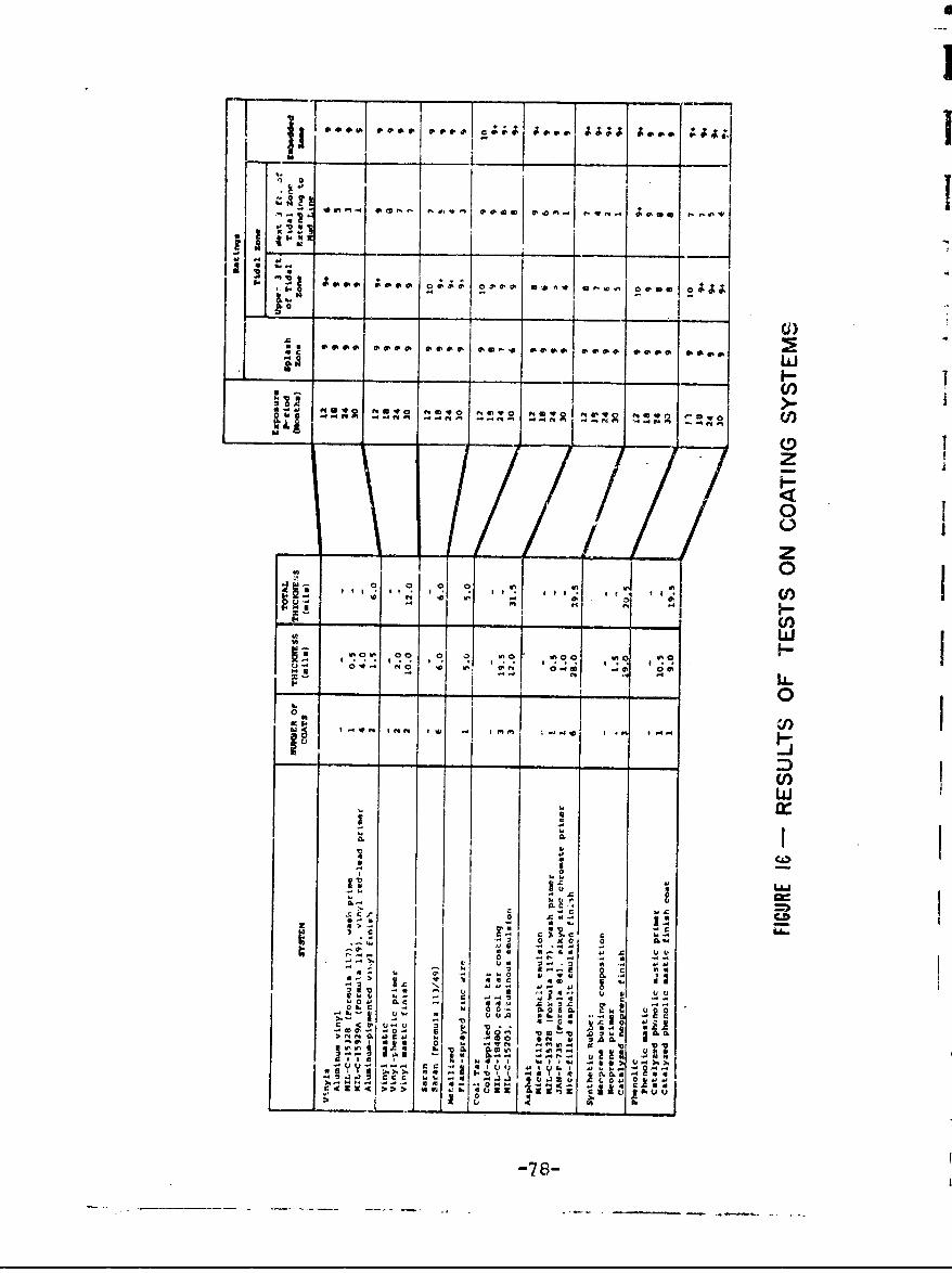
-. ........
_____ _____ _o____A;* A o * 4
-s In 'D v -ý 4FaOD00)
£us ~e. q~p~*EIe~ *.~.o *e~p .. , 9~e ... *.i).
*.M ~ ~ ~ ~ ~ t w ft4UIV ft~ 01, @WO NY .w m
_ _ -~ _ _
zMo
0
~ ml m e. me I. (f)
0 0A
rE cII zf.1
I rwi w.,0 0 3 wf C V3*0 Z1
0- 0Y 0.O .1 (L u - e .. o
2 . Is 0
'0 H 5a *1
of coatings with relatively long protective life at reason-ably economical costs.
J In Situ Applicition
For coatings to be used as a maintenance technique forbulkheads, they must be capable of being applied in situafter the initial coating has lost its effectiveness. Sincethe useful lifetime of presently available coatings is inthe range of two to seven years, it is apparent that suchin situi application is much more important than initial ap-plicatio; Painting or otherwise coating a structure abovethe water line is relatively straightforward as long as de-posited salts and corrosion products are removed and appli-cation to a clean, dry surface is possible. Below the waterline, however, coating is difficult.
One system which has been shown to be somewhat effec-tive for in situ underwater application is a two-pack epoxycoating. Heavy epoxy coatings can be applied by forming orhand lay-up techniques. The cured coating can be expectedto protect the base metal against corrosion for several ad-ditional years. To date, such applications have been madeonly to surfaces cleaned down to bare white metal. Costshave been in the $5 per square-foot range. While thismagnitude of cost might be justified on H-piling, whereeach member may carry a concentrated load from an expensivesuperstructure, it is economically questionable for sheet-steel piling installations.
S1i Another approach to coating underwater areas is localdewatering. A box containing equipment is placed with itsopen side against the surface to be coated. The box issealed to the surface with rubber gaskets and is thcn de-watered. The coating is applied by the equipment in thebox, which is activated and fed from outside the dewateredzone.
In addition to the pocsible use of organic and inor-ganic .coatings to recoat underwater areas, in situ metalcoatings should be considered. As discussed above in thesectioii on metal coatings, metal spraying and in situ elec-troplating can be field-applied.
-79-I..
SV. REPAIR TECHNIQUES AND MATERIALS
If a sheet-steel bulkhead installation has not beenregularly maintained by such techniques as cathodic pro-tection and periodic recoating, progressive deteriorationwill occur. Sheet-steel piling structures suffer progressivedeterioriation as a result of several influences:
Corrosion from the sea water causes loss ofmetal in the splash zone and in the activeelectrolytic zone a short distance below thewater line. Perforation through gross lossof metal or wear can then lead to loss offill material from behind the bulkhead.
Mechanical abrasion caused by the impact ofwave-carried material and by scouring at thetoe of the wall also contribute to the pro-gressive deterioration on the sea side of thej bulkheads. Similar effects on the shore sideof the structure can also lead to deterioration.
Progressive changes in alignment can resultfrom poor anchoring support, irregular soilcharacteristics, or tie-rod failure.
Corrosion due to ground water movements orstray curints can cause perforation of thesheet steel from the back side.
Two methods of correcting the deterioration of sheet-steel bulkheads, by replacement with new installationi andby preventive maintenance techniques, have been consideredin detail in earlier sections of this report. Techniquesfor the repair of badly deterioratee steel bulkheads areconsidered in this section.
Once significant rusting or erosion has occurred, repairtechniques must be employed to return the structure to itsdesign condition or to arrest further detericration. Cor-rective measures taken may vary considerably in complexity,depending upon the desired lifetime and cost parameters.
-80-
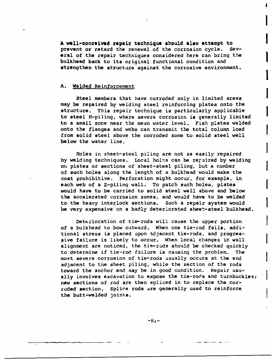
I
A well-aonceived repair technique should also attempt to Iprevent or retard the renewal of the corrosion cycle. Sev-eral of the repair techniques considered here can bring thebulkhead back to its original functional condition andstrengthen the structure against the corrosive environment. IA. Welded Reinforcement
Steel members that have corroded only in limited areasmay be repaired by welding steel reinforcing plates onto thestructure. This repair technique is particularly applicableto steel H-piling, where severe corrosion is generally limitedto a small zone near the mean water level. Fish plates weldedonto the flanges and webs can transmit the total column loadfrom solid steel above the corroded zone to solid steel wellbelow the water line.
Holes in sheet-steel piling are not as easily repairedby welding techniques. Local holes can be repaired by weldingou plates or sections of sheet-steel piling, but a numberof such holes along the length of a bulkhead would make thecost prohibitive. Perforation might occur, for example, ineach web of a Z-piling wall. To patch such holes, plates Iwould have to be carried to solid steel well above and belowthe accelerated corrosion zones, and would have to be weldedto the heavy interlock sections. Such a repair system would Ibe very expensive on a badly deteriorated sheet-steel bulkhead.
Deterioration of tie-rods will cause the upper portionof a bulkhead to bow outward. When one tie-rod fails, addi-tional stress is placed upon adjacent tie-rods, and progres-.sive failure is likely to occur. When local changes in wall Ialignment are noticed, the tie-rods should be checked quicklyto determine if tie-rod failure is causing the problem. Themost severe corrosion of tie-rods usually occurs at the end Iadjacent to the sheet piling, while the section of the rodstoward the anchor end may be in good condition. Repair usu-ally involves excavation to expose the tie-rods and turnbuckles;new sections of rod are then spliced in to replace the cor-roded section. Splice rods dre generally used to reinforcethe butt-welded joints. I
- 8i -

IA
I 1
II B Concrete Technius
If a deteriorated sheet-steel bulkhead still has adequatestrength to support the applied loads below some section,concrete encasement down to that section can be used to pre-vent further deterioration arc. to seal perforated areas againstloss of fill! This technique is applicable to corroded H-piling sections, where the concrete is used to transmi~t col-
I umn stresses; as well as to sheet-steel bulkheads.
Depending upon the relative severity of attack on theinside and outside face. 3f a sheet-steel piling wall, en-casement may be extended to cover both faces. Althoughprotection of both faces is expensive, because of additionalexcavation and material costs, beneficial protection can beI derived if the encas inent is carried down far enough to in-clude the wales and tie-rod ends. Since corrosion ratesgenerally fall off rapidly below the active electrolyticzone in sheet-steel piling, the concrete encasement needs tobe carried down only a few feet below the mean low water lev-el. If abrasion or corrosion of the balance of the submergedsheet piling is unusually severe, the concrete encasement canbe extended to the miud line. If the lower end of the encase-ment form is submerged but does not reach the mud line, acounterweight outrigger beam can be used to support the form.Encasement techniques were used at NAS(NY) and will be dis-IJ cussed in Sections VIII and IX.
Concrete may also be used to repair sheet-steel bulkheaddeterioration by spot patching. If concrete plugs are usedto seal perforations 'in the sheet-steel bulkhead, loss offill material will be stopped. To place a concrete patchI I so that it is supported behind the bulkhead wall at the edgeof the perforation, a cavity must be prepared or provisionmust be made to place the concrete under pressure or impact
! j in order to displace the fill material. Since ground wateris likely to be flowing through the perforation from behindthe wall, neither of these techniques is easy. Corrosiondeterioration will continue on adjacent areas of the steelpiling, and spot patching has limited effectiveness as a re-pair technique unless it is applied each time a new perfora-tion appears.
-'8-82-

A third possibility for the use of concrete to stabilizedeteriorated bulkhead walls is that of grouting the fillmaterial behind the wall to make it self-supporting. Thisalternative would not prevent further deterioration of thebulkhead, but would simply use the bulkhead as a form forthe pressure-grouting operation. The possibility of usinga pressure-grouting technique is limited by the characteris-tics of the backfill material and by the geometry of thebulkhead installation. Deep grouting is not possible ingranular soils; iL leads to side shifting of the fill, ratherthan deep penetration. Grout may also flow out through per-forations and not help to compact soil adjacent to the per-foration.
C. Rip-Rap
If the structural integrity of a bulkhead has been im-paired by deterioration, a new structural support system isrequired, rather than encasement to prevent further deteriora-tion. If the bulkhead is still standing and retaining thebackfill, a rip-rap installation in front of the bulkheadmay be an attractive solution. The rip-rap wall would bedesigned with sufficient bulk to resist the overturningmoment of the backfill, even if the original bulkhead wereentirely ineffective. The toe of the rip-rap fill would becut into the bottom to a depth of approximately one wave-height below the normal mud line, in order to prevent under-cutting caused by erosion of the support material. The rip-rap material would be graded with fine material near thewall and coarse material at the outside face, to provide agraded filter against loss of the fill material and maximumstability against wave action.
D. New Facing
One technique for preventing further deterioration ofa sheet-steel bulkhead, already applied above in the concreteencasement solution, is to place a new structure between thebulkhead and the sea water. A new facing which is resistantto the marine environment can be placed in front of the orig-inal bulkhead and inert fill inserted between the two. If
-83-
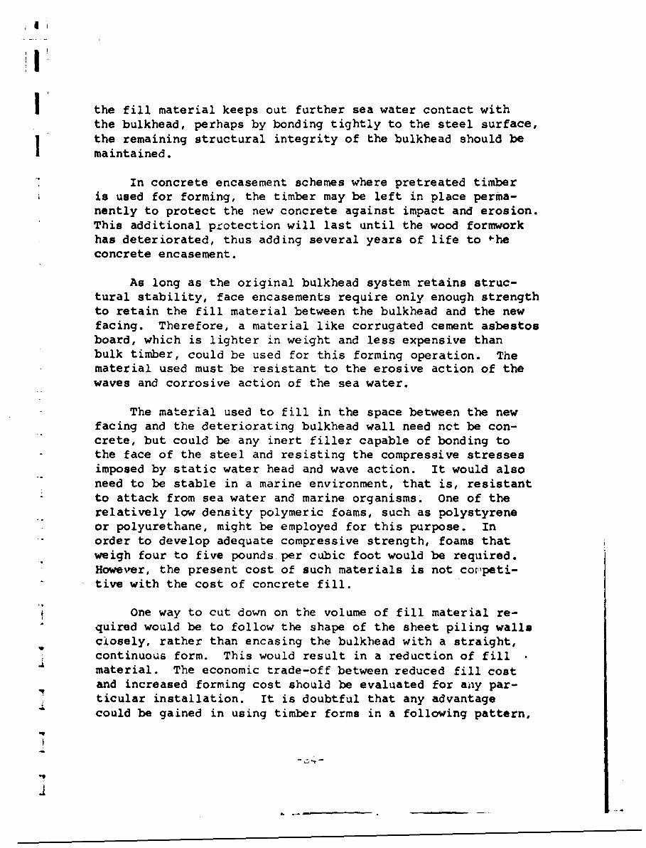
S|I
the fill material keeps out further sea water contact withthe bulkhead, perhaps by bonding tightly to the steel surface,the remaining structural integrity of the bulkhead should bemaintained.
In concrete encasement schemes where pretreated timber£ is used for forming, the timber may be left in place perma-
nently to protect the new concrete against impact and erosion.This additional protection will last until the wood formworkhas deteriorated, thus adding several years of life to -heconcrete encasement.
As long as the original bulkhead system retains struc-tural stability, face encasements require only enough strengthto retain the fill material between the bulkhead and the newfacing. Therefore, a material like corrugated cement asbestosboard, which is lighter in weight and less expensive thanbulk timber, could be used for this forming operation. Thematerial used must be resistant to the erosive action of thewaves and corrosive action of the sea water.
The material used to fill in the space between the newfacing and the deteriorating bulkhead wall need nct be con-crete, but could be any inert filler capable of bonding tothe face of the steel and resisting the compressive stressesimposed by static water head and wave action. It would alsoneed to be stable in a marine environment, that is, resistantto attack from sea water and marine organisms. One of therelatively low density polymeric foams, such as polystyreneor polyurethane, might be employed for this purpose. Inorder to develop adequate compressive strength, foams thatweigh four to five pounds. per cubic foot would be required.However, the present cost of such materials is not coopeti-tive with the cost of concrete fill.
One way to cut down on the volume of fill material re-"quired would be to follow the shape of the sheet piling wallsclosely, rather than encasing the bulkhead with a straight,continuous form. This would result in a reduction of fillmaterial. The economic trade-off between reduced fill costand increased forming cost should be evaluated for any par-ticular installation. It is doubtful that any advantagecould be gained in using timber forms in a following pattern,
.9
-9
4
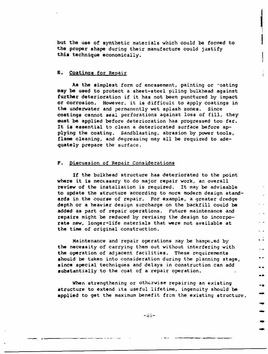
but the use of synthetic materials which could be formed tothe proper shape during their manufacture could justifythis technique economically.
E. Coatings for Repair
As the simplest form of encasement, painting or -oatingmay be used to protect a sheet-steel piling bulkhead againstfurther deterioration if it has not been punctured by impactor corrosion. However, it is difficult to apply coatings inthe underwater and permanently wet splash zones. Sincecoatings cannot seal perforations against loss of fill, theymust be applied before deterioration has progressed too far.It is essential to clean a deteriorated surface before ap-plying the coating. Sandblasting, abrasion by power tools,flame cleaning, and degreasing may all be required to ade-quately prepare the surface.
F. Discussion of Repair Considerations
If the bulkhead structure has deteriorated to the pointwhere it is necessary to do major repair work, an overallreview of the installation is required. It may be advisableto update the structure according to more modern design stand-ards in the course of repair. For example, a greater dredgedepth or a heavier design surcharge on the backfill could beadded as part of repair operations. Future maintenance andrepairs might be reduced by revising the design to incorpo-rate new, longer-life materials that were not available atthe time of original construction.
Maintenance and repair operations may be hampe.red by -.
the necessity of carrying them out without interfering withthe operation of adjacent facilities. These requirementsshould be taken into consideration during the planning stage,since special techniques and delays in construction can addsubstantially to the cost of a repair operation.
When strengthening or otherwise repairing an existingstructure to extend its useful lifetime, ingenuity should beapplied to get the maximum benefit frcm the existing structure.
-oSl-
Sma

The optimal use of the existing structure is particularlyimportant in large-scale projects where one repair techniquep is to be applied repetitively.
After many years of deterioration, the remaining stabil-ity of a bulkhead may be due to mechanisms other than thosesupplied in the original design. The existing constructionshould not be disturbed until it has been thoroughly checkedto ascertain its long-term stability. Such a detailed checkis necessary before any corrective repair can be designed.
a
* IAfter the deterioration of a bulkhead installation hasbeen arrested by application of repair techniques, periodic
I maintenance where warranted should be instituted to preventI the occurrence of a new cycle of deterioration. If a coating
were applied above the water line, for example, it should bemaintained as a continuous cover.
I
lo
I
"I
.pU -. ,
-86-
agoe
VI. ENVIRONMENTAL FACTORS IN BULKHEAD DESIGN
In the preceding sections, numerous methods and materials
for repairing, replaci.ncg, and maintaining steel bulkheads havebeen discussed, many of ",hich show promise of extending thelife of a bulkhead by . incromentli period of time. Toreduce the number of altern-atives, before invest-. gating the costframework against which the alternati.ves must be judged, theenvironmental factors at the bulkhe-ad site should be considered.
Ti.ere are many environme.,tal fa. ors to be considered, andthe relative importance of eac varies 1ith the bulkhead site.In some locations, ec-'nomic fac ors scn as availability offunds, proximity of dcpeident struczur.;s, and availability ofskilled personnel may predominate in the selection of a materialsystem. In other locations, climatic conditions ard biologicalfactors are most importar in the selection of a bulkhead system.No two loca.ions are subie-t to the same condit.ions, and signif-icant variations can even be found within the same harbor.While it is not possible -o review all environmental factors inthis study, the more imoo tant ones are discussed, and the con-ditions under which thr e factors are important are reviewed.
A. Economic Environment
The economic environment is made up of several factors.For example, availability of funds will determine whether ornot work can be done. The cost :,f failure must be considered,including the cost of potential damage to adjacent facilities.Finally, administrative personnel, contractors, inspectors,...nd other skilled people m'ist be available.
Lmnding
Obhaining funds for public works is always difficult andbulkhead work ,suall- does 4ot have a high proirity, since abulkhead mainly. has a .assive role in the mission of a base.Bulkhead protects cc-:ete with many other pro-ects for avail-able maintenance and re-air funds. At present, expendituresfor installation of a bulkhead are usually tied to a largerproject. ALthoh rep1Eceý.e.t cf old installations might bedesirable, their reoalr ma, be the only course of actionpossible dae to Financa`l censtraznts.
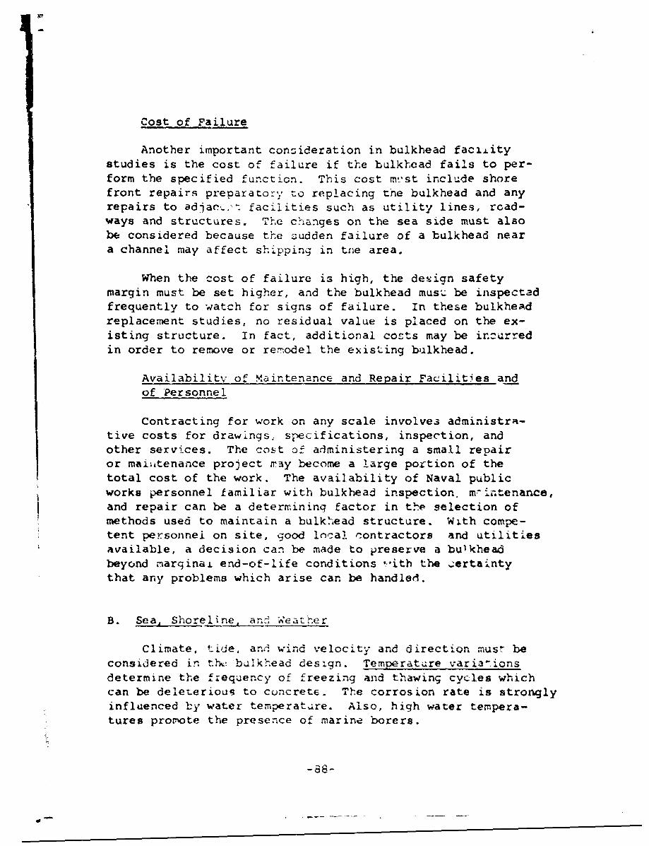
Cost of Failure
Another important consideration in bulkhead faciiitystudies is the cost of failure if the bulkhead fails to per-form the specified function. This cost mst include shorefront repairs preparatory to replacing the bulkhead and anyrepairs to adjacv,.-t facilities such as utility lines, road-ways and structures. The changes on the sea side must alsobe considered because the sudden failure of a bulkhead neara channel may affect shipping in tne area.
When the cost of failure is high, the design safetymargin must be set higher, and the bulkhead must• be inspectedfrequently to watch for signs of failure. In these bulkheadreplacement studies, no residual value is placed on the ex-isting structure. In fact, additional costs may be incurredin order to remove or rem.odel the existing bulkhead.
Availability of Maintenance and Repair Facilities andof Personnel
Contracting for work on any scale involves administra-tive costs for drawi.ngs. specifications, inspection, andother services. The cost of administering a small repairor maii~tenance project may become a large portion of thetotal cost of the work. The availability of Naval publicworks personnel familiar with bulkhead inspection, mintenance,and repair can be a determining factor in the selection ofmethods used to maintain a bulkhead structure. With compe-tent personnel on site, good local contractors and utilitiesavailable, a decision can be made to preserve a bulkheadbeyond marginai end-of-life conditions ,''itb the ;erta*ntythat any problems which arise can be handled.
B. Sea, Shoreline, an§ Weatner
Climate, tide, anl wind velocity and direction must beconsidered in tYh buTkhead design. Temperature varia-ionsdetermine the frequency of freezing and thawing cycles whichcan be deleterious to concrete. The corrosion rate is stronglyinfluenced by water temperature. Also, high water tempera-tures protote the presence of marine borers.
-86-
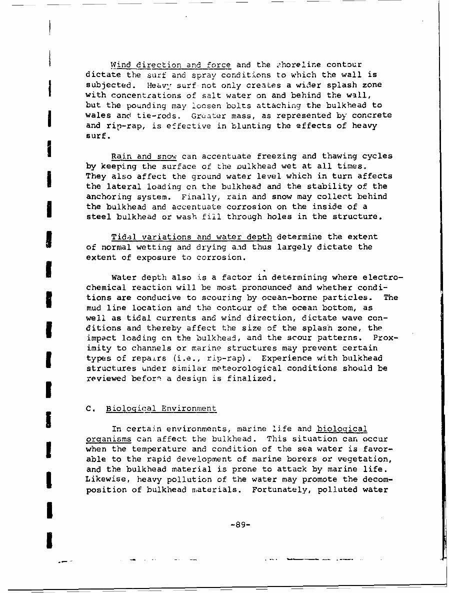
I Wind direction and force and the Thoreline contourdictate the surf and spray conditions to which the wall issubjected. Heavy surf not only creates a wider splash zonewith concentrations of salt water on and behind the wall,but the pounding may loosen bolts attaching the bulkhead towales and tie-rods. Greater mass, as represented by concreteand rip-rap, is effective in blunting the effects of heavysurf.
I Rain and snow can accentuate freezing and thawing cyclesby keeping the surface of Lhe Dulkhead wet at all times.They also affect the ground water level which in turn affectsthe lateral loading cn the bulkhead and the stability of theanchoring system. Finally, rain and snow may collect behindthe bulkhead and accentuate corrosion on the inside of asteel bulkhead or wash fill through holes in the structure.
Tidal variations and water depth determine the extentof normal wetting and drying and thus largely dictate theextent of exposure to corrosion.
I Water depth also is a factor in determining where electro-chemical reaction will be most pronounced and whether condi-tions are conducive to scouring by ocean-borne particles. Themud line location and the contour of the ocean bottom, aswell as tidal currents and wind direction, dictate wave con-ditions and thereby affect the size of the splash zone, theimpact loading cn the bulkhead, and the scour patterns. Prox-imity to channels or marine structures may prevent certaintypes of repairs (i.e., rip-rap). Experience with bulkheadstructures under similar meteorological conditions should bereviewed before a design is finalized.IC. Biological Environment
In certain environments, marine life and biologicalorganisms can affect the bulkhead. This situation can occurwhen the temperature and condition of the sea water is favor-able to the rapid development of marine borers or vegetation,and the bulkhead material is prone to attack by marine life.Likewise, heavy pollution of the water may promote the decom-position of bulkhead materials. Fortunately, polluted water
8-89-
I

inhibits the development of marine life so that these effectstend to offset each oth-.er.
Marine borers, barnacles, and vegetation attached tobulkhead walls can accelerate normal corrosion and erosionpatterns. Lacking experience with timber structures at anintended location, it is wise to place some wood samples inthe water to test for marine attack before selecting a ztruc-tural design with exposed timber. Preservatives will sealtimber from attack by marine life, but the preservation mustbe done under factory conditions; the same degree of protac-tion cannot be obtained on the construction site. Whc.-eve2possible, timber structures for marine use should be pre.fabri.-cated and treated at the mill. If the preservative coatingcannot be kept completely intact during installation, i r maybe impractical to use a timber facing, or it may be necessaryto sheath exposed wood with aluminum or copper.
Pollution in sea or harbor waters usually does not affectstructures as much as electrochemical corrosion or rusting.When pollution is severe, however, it may cause extensivecorrosion. The section of a wall nearest to the sewage-ladeneffluent is the area affected most severely. Peak corrosionmay take place at or near the mud line when sludge is allowedto accumulate. If pollution is the major problem, concreteis the most desirable structural material because steeland timber are both affected by chemical and biologicalpollutants.
D. Other Factors
Other factors that may have a bearing on bulkhead
material selection are:
• the presence of stray currents;
. the development of a thick scale on steelor heavy vegetation on timber; and
. mechanical abrasion and impact loading dueto ships.
When any of these factors outweigh normal wear due to erosionand corrosion, the bulkhead design must be tailored to fitthese special conditions.
-90-
Ii
II
,Stray currents due to electrical generators, radio andmicrowave equipment, and fLulty transformer grounds acceleratethe decomposition of sheet-metal piling, fasteners, and con-
Screte reinforcing bars. Direct current sources are especiallydangerous. The source of the current does not have to beclose to the bulkhead to affect it. In many cases, electricalequipment is grounded to a soil pipe which, if placed in wetsoil, can carry a stray current a long distance. If testsor previous experience have shown the presence of groundcurrents, cathodic protection of steel or use of electricallyinert materials may be necessary.
The nature and thickness of scale and attached marineI.iL.e may prevent the use of some maintenance and repairtechniques, since most coating materials and penetrants mustbe applied over a clean dry surface. If scale cannot be re-moved or must be removed with great difficulty, maintenancemay become impractical. Sandblasting or peening of a heavilycorroded wall may result in perforation. In cases of thistype, replacement may be the only solution. Also, the re-moval of vegetation from timber may expose the structureto borers.
Each of the environmental factors considered may be pre-I" dominant enough to affect the design of a bulkhead or to al-
ter the use of bulkhead installation, maintenance and repairmethods, or materials. Usually, however, a combination ofr ~environmental factors is required before a change in the de-
sign or the selection of methods and materials is necessary.7In order to arrive at the best design, the effect of the en-vironment on bulkheads in the area should be studied and aIcombined value placed on all the environmental factors for
1• economic and design evaluations.
L 91
1
I
1 VII. ANALYSIS OF BULKHEAD INSTALLATION,MAINTENANCE, AND REPAIR COSTS
The methods and materials adaptable to shoreline con-
struction have been explored in Sections III, IV, and V, andthe environmental factors relating to design and installationhave been examined in Section VI. In this section the eco-nomics of bulkhead construction and maintenance will be! explored.
I A. General Cost Considerations
In the fiscal sense, a bulkhead represents a stream ofpayments in return for a service performed to the Navy. Acertain sum is expended for initial installation of thebulkhead. Additional sums may be spent at some future date
Sto maintain or repair the wall. Finally, when the originalstructure is no longer able to perform its function, addition-al money is spent to replace it. If the functional require-ment for a wall continues, the stream of payments goes onindefinitely.
I Comparison of two or more alternative bulkhead systemsis complicated by the fact that expenditures may not takeplace in the same years. The problem of comparing non-uniform expenditures over varying periods of time, wheremoney has a time value, can be simplified by using the annualcost method. The annual cost method allows the analyst toI reduce the actual expenditures during the life of the bulk-head to a series of uniform yearly payments. In essence,the annual cost represents the amount that would be paideach year to amortize the initial installation costs, theinterest accumulated on that sum, and all maintenance and
Srepair costs until replacement. Then, the replacement costJ may also be amortized at the same rate. Classically, a com-
parison drawn on this basis should cover the alternativesover an equal period of time. However, when the comparabletime periods represent one or more bulkhead replacement per-iods, differences due to amortization periods are insignif-
J icant.
1 -92-
I
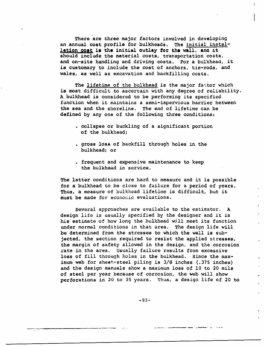
There are three major factors involved in developingan annual cost profile for bulkheads. The initial instal-lation poajt is the initial outlay for the wall, ana itshould include the material costs, transportation costs,and on-site handling and driving costs. For a bulkhead, itis customary to include the cost of anchors, tie-rods, andwales, as well as excavation and backfilling costs.
The lifetime of the bulkhead is the major fa'ctor whichis most difficult to ascertain with any degree of reliability.A bulkhead is considered to be performing its specifiedfunction when it maintains a semi-impervious barrier betweenthe sea and the shoreline. The end of lifetime can bedefined by any one of the following three conditions:
". collapse or buckling of a significant portionof the bulkhead;
". gross loss of backfill through holes in thebulkhead; or
"* frequent and expensive maintenance to keepthe bulkhead in service.
The latter conditions are hard to measure and it is possiblefor a bulkhead to be close to failure for a period of years.Thus, a measure of bulkhead lifetime is difficult, but itmust be made for economic evaluations.
Several approaches are available to the estimator. Adesign life is usually specified by the designer and it ishis estimate of how long the bulkhead will meet its functionunder normal conditions in that area. The design life willbe determined from the stresses to which the wall is sub-jected, the section required to resist the applied stresses,the margin of safety allowed in the design, and the corrosionrate in the area. Usually failure results from excessiveloss of fill through holes in the bulkhead. Since the max-imum web for sheet-steel piling is 3/8 inches (.375 inches)and the design manuals show a maximum loss of 10 to 20 milsof steel per year because of corrosion, the web will showperforations in 20 to 35 years. Thus, a design life of 20 to
-93-
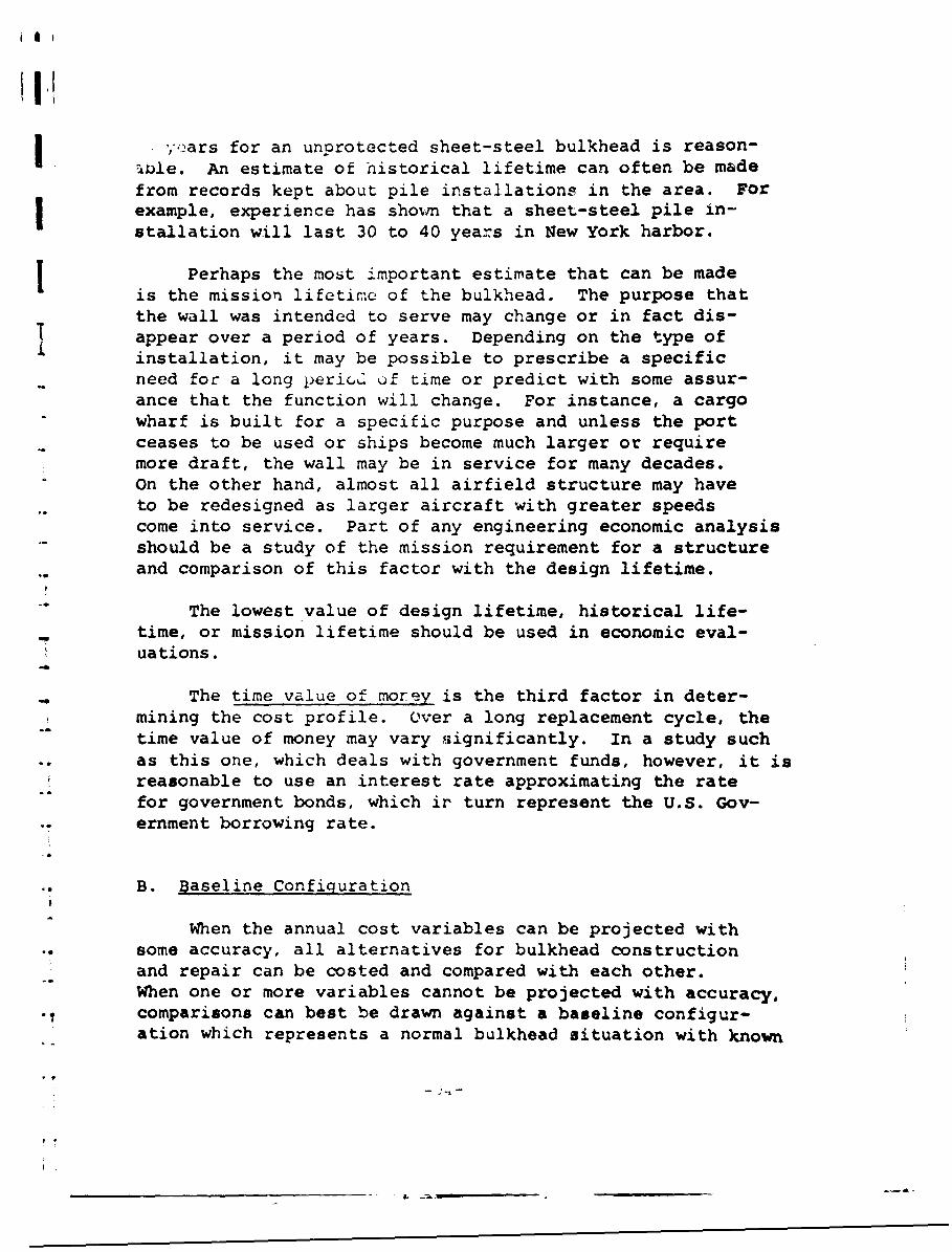
I.'
'II
,,iŽars for an unprotected sheet-steel bulkhead is reason-4ule. An estimate of historical lifetime can often be madefrom records kept about pile installations in the area. Forexample, experience has shown that a sheet-steel pile in-stallation will last 30 to 40 years in New York harbor.
is Perhaps the most important estimate that can be madeis the mission lifetime of the bulkhead. The purpose thatthe wall was intended to serve may change or in fact dis-appear over a period of years. Depending on the type ofinstallation, it may be possible to prescribe a specificneed for a long peric" of time or predict with some assur-ance that the function will change. For instance, a cargo"wharf is built for a specific purpose and unless the portceases to be used or ships become much larger or requiremore draft, the wall may be in service for many decades.On the other hand, almost all airfield structure may haveto be redesigned as larger aircraft with greater speedscome into service. Part of any engineering economic analysisshould be a study of the mission requirement for a structureand comparison of this factor with the design lifetime.
"The lowest value of design lifetime, historical life-time, or mission lifetime should be used in economic eval-uations.
The time value of morey is the third factor in deter-mining the cost profile. Over a long replacement cycle, thetime value of money may vary significantly. In a study such
.. as this one, which deals with government funds, however, it isreasonable to use an interest rate approximating the ratefor government bonds, which ir turn represent the U.S. Gov-ernment borrowing rate.
B. Baseline Configuration
When the annual cost variables can be projected withsome accuracy, all alternatives for bulkhead constructionand repair can be costed and compared with each other.When one or more variables cannot be projected with accuracy,
• • comparisons can best be drawn against a baseline configur-ation which represents a normal bulkhead situation with known
__________________________- L .
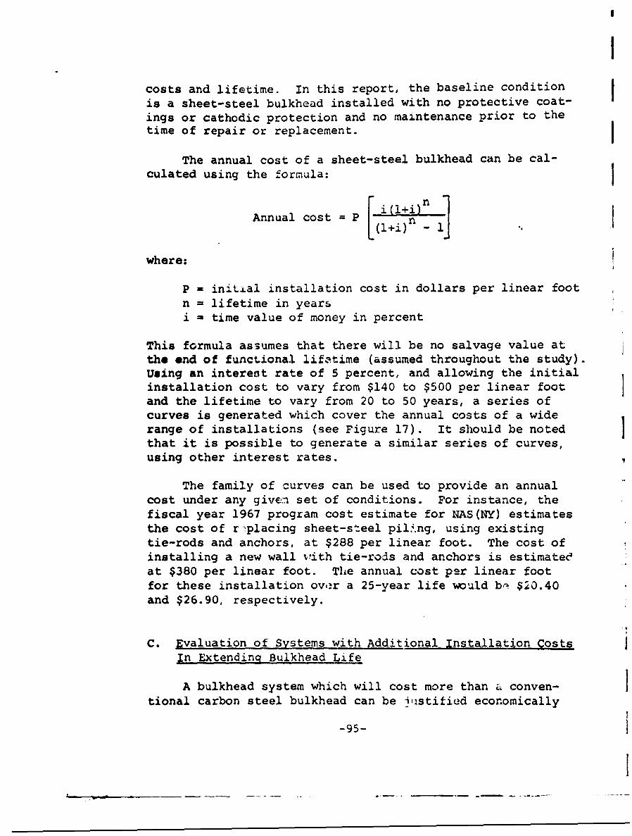
I
costs and lifetime. In this report, the baseline condition_is a sheet-steel bulkhead installed with no protective coat-ings or cathodic protection and no maintenance prior to thetime of repair or replacement.
The annual cost of a sheet-steel bulkhead can be cal-culated using the formula:
Annual cost = P [l+imn 1]
where:
P - initial installation cost in dollars per linear footn = lifetime in yearsi = time value of money in percent
This formula assumes that there will be no salvage value atthe end of functional lifitime (assumed throughout the study).Using an interest rate of 5 percent, and allowing the initialinstallation cost to vary from $140 to $500 per linear footand the lifetime to vary from 20 to 50 years, a series ofcurves is generated which cover the annual costs of a widerange of installations (see Figure 17). It should be notedthat it is possible to generate a similar series of curves,using other interest rates.
The family of curves can be used to provide an annualcost under any given set of conditions. For instance, thefiscal year 1967 program cost estimate for NAS(NY) estimatesthe cost of r-placing sheet-steel pil4.ng, using existingtie-rods and anchors, at $288 per linear foot. The cost ofinstalling a new wall v'ith tie-rods and anchors is estimateeat $380 per linear foot. The annual cost per linear footfor these installation over a 25-year life would b,- $20.40and $26.90, respectively.
C. Evaluation of Systems with Additional Installation CostsIn Extendinq Bulkhead Life
A bulkhead system which will cost more than a conven-tional carbon steel bulkhead can be i'istified economically
-95-
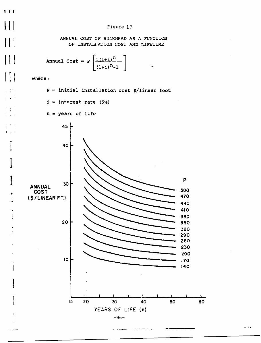
IH Figure 17
ANNUAL COST OF BULKHEAD AS A FUNCTIONIII OF INSTALLATION COST AND LIFETIME
I I IAnnual Cost = P [j( 1+i)n 1
I I where:
P initial installation cost $/linear foot
i =interest rate (5%)
n = years of life
45
£ 40
ANNUAL 500COST50
($/LINEAR FT.) 470440410380
20 350
260230200
10 1701 140
15 20 30 40 50 60YEARS OF' LIFE (n)
1 -96-
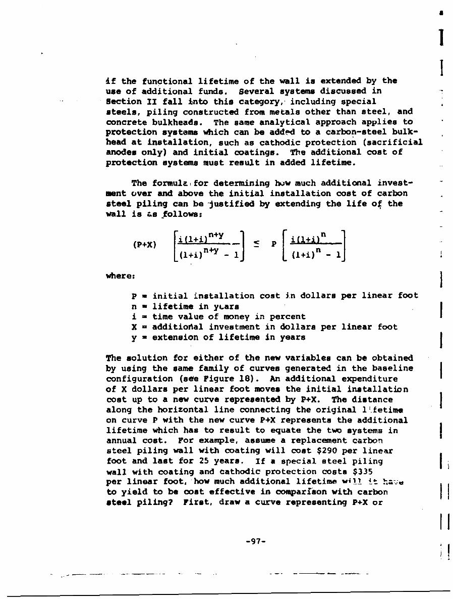
II
if the functional lifetime of the wall is extended by theuse of additional funds. Several systems discussed inSection II fall Into this category, including specialsteels, piling constructed from metals other than steel, andconcrete bulkheads. The same analytical approach applies toprotection systems which can be addoAd to a carbon-steel bulk-head at installation, such as cathodic protection (sacrificialanodes only) and initial coatings. The additional cost ofprotection systems must result in added lifetime.
The formula for determining hvw much additional invest-ment over and above the initial installation cost of carbonsteel piling can be justified by extending the life of thewall is as follows:
(P+X) [1(+i)n+y - L P (l+i)n - 'J
where: J
P = initial installation cost in dollars per linear footn - lifetime in yLarsi - time value of money in percentX = additiodial investment in dollars per linear footy = extension of lifetime in years
The solution for either of the new variables can be obtainedby using the same family of curves generated in the baselineconfiguration (see Figure 18). An additional expenditureof X dollars per linear foot moves the initial installationcost up to a new curve represented by P+X. The distancealong the horizontal line connecting the original 1:.fetimeon curve P with the new curve P+X represents the additionallifetime which has to result to equate the two systems inannual cost. For example, assume a replacement carbonsteel piling wall with coating will cost $290 per linearfoot and last for 25 years. If a special steel pilingwall with coating and cathodic protection costs $335per linear foot, how much additional lifetime w4'! !4t lh~a-ato yield to be cost effective in comparlson with carbonsteel piling? First, draw a curve representing P+X or
-97-
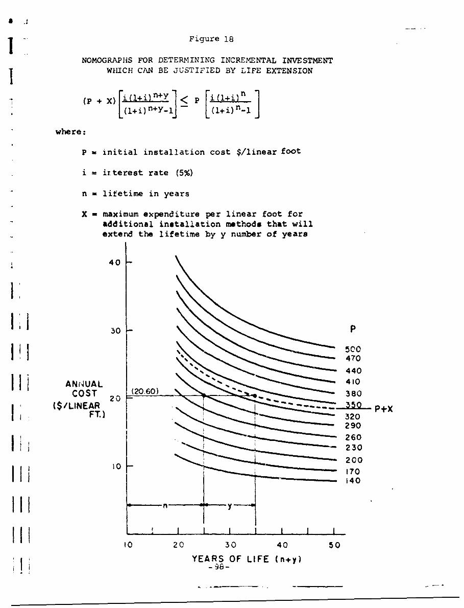
V Figure 18
NOMOGRAPHS FOR DETERMINING INCREMENTTAL INVESTMENTWk1ICH CAN BE JUSTIFIED BY LIFE EXTENSION
(P+ X) [)+ i(+
L(1+ i) Y1J 11e)n
where:
P = initial installation cost $/linear foot
i = ir~terest rate (5%)
n -lifetime in years
X = maximum expenditure per linear foot foradditional installation methods that willextend the lifetime by y number of years
40
li50 -P
1' 500% 470
440
I LANNUAL 20410COST (0.60)380
229
260
2300
I Ii170140
0203 0 4 0 5 0
YEARS OF LIFE (n+y)Ii - 98-

l
$335 per linear foot. Then, connect the point representing25-year lifetime on the P curve ($290 per linear foot) andthe new curve with a horizontal line. The answer is 10years of additional life, which will justify the increasedexpenditure.
Some general conclusions can be drawn by observing thejuxtaposition of the c•vcs in Figure 18. First, if thebaseline configuration iaszz 20 years or less, increasedexpenditures of 20 percent or more cai be justified by lessthan 10 years of additional life. As the baseline config-uration increases in functional life, the increased instal-lation expenditures must be justified by much longer ex-tensions of bulkhead life. Second, if the baseline config-uration lasts even 20 years, as the bulkhead at the NAS (NY)has done, no amount of additicnal life will justify an ex- Ipenditure of more than twice the initial installation cost.This observation effectively rules out the use of high-costmetals, such as titanium or nickel, or concrete cast-in-place to considerable depths. Third, a relatively smallincremental installation cost such as coating (5 to 15dollars per linear foot), installation of cathodic protection I(10 to 15 dollars per linear foot), and concrete coping(20 dollars per linear foot) can be justified with a veryshort increase in the functional lifetime when the originalbulkhead lifetime without these features is 25 years or less.
D. &valuation of Annual Maintenance Costs in FExteidingBulkhead Life
Annual maintenance may be economically undertaken ifthe cost is less than tne reduction in annual cost engenderedby increased lifetime. Among the techniques which could beperformed Cn an annual basis that may extend "ifetine arepainting, scalin6 g and defouling, and impressed cu.-ren*tcathodic protection.
The formula for determining how much ar,;ul maintenancecan be performed to develop a life extpnsion of y years isas fQllows:
-99-
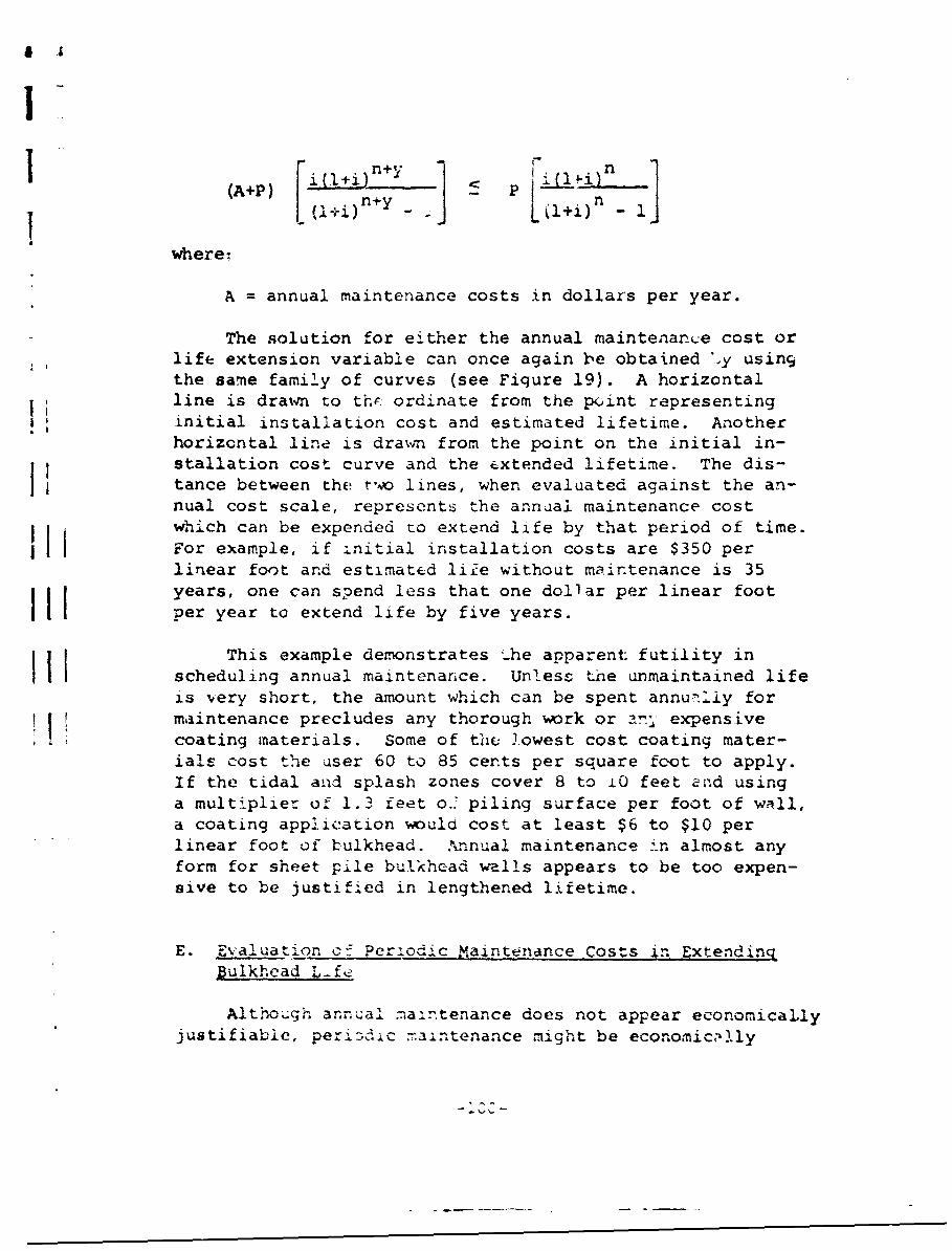
I
'+p' i:~:n+Y ~ pL l)l
where:
A = annual maintenance costs in dollars per year.
The solution for either the annual maintenance cost orlife extension variable can once again be obtained ',y usingthe same family of curves (see Fiqure 19). A horizontalline is drawn to thr. ordinate from the point representinginitial installation cost and estimated lifetime. Anotherhorizontal line is drawý-n from the point on the initial in-stallation cost curve and the extended lifetime. The dis-f tance between the two lines, when evaluated against the an-nual cost scale, represents the annual maintenance costwhich can be expended to extend life by that period of time.For example, if initial installation costs are $350 perlinear foot and estimated liie without maintenance is 35years, one can spend less that one dollar per linear footper year to extend life by five years.
This example demonstrates The apparent: futility inscheduling annual maintenance. Unless the unmaintained lifeis very short, the amount which can be spent annu--Iiy formaintenance precludes any thorough work or ary expensivecoating materials. Some of the Jowest cost coating mater-ials cost the user 60 to 85 cents per square foot to apply.If the tidal and splash zones cover 8 to L0 feet and using"a multiplier of 1.3 feet o.' piling surface per foot of wall,"a coating application woula cost at least $6 to $10 perlinear foot of bulkhead. .knnual maintenance in almost anyform for sheet pile bulkhead wells appears to be too expen-sive to be justified in lengthened lifetime.
E. Evaluation of Periodic Maintenance Cost*s in ExtendingBulkhead .Lf2
Although annual maintenance does not appear economicallyjustifiable, peri3cJic raintenance might be economicaJIly
-i, '-
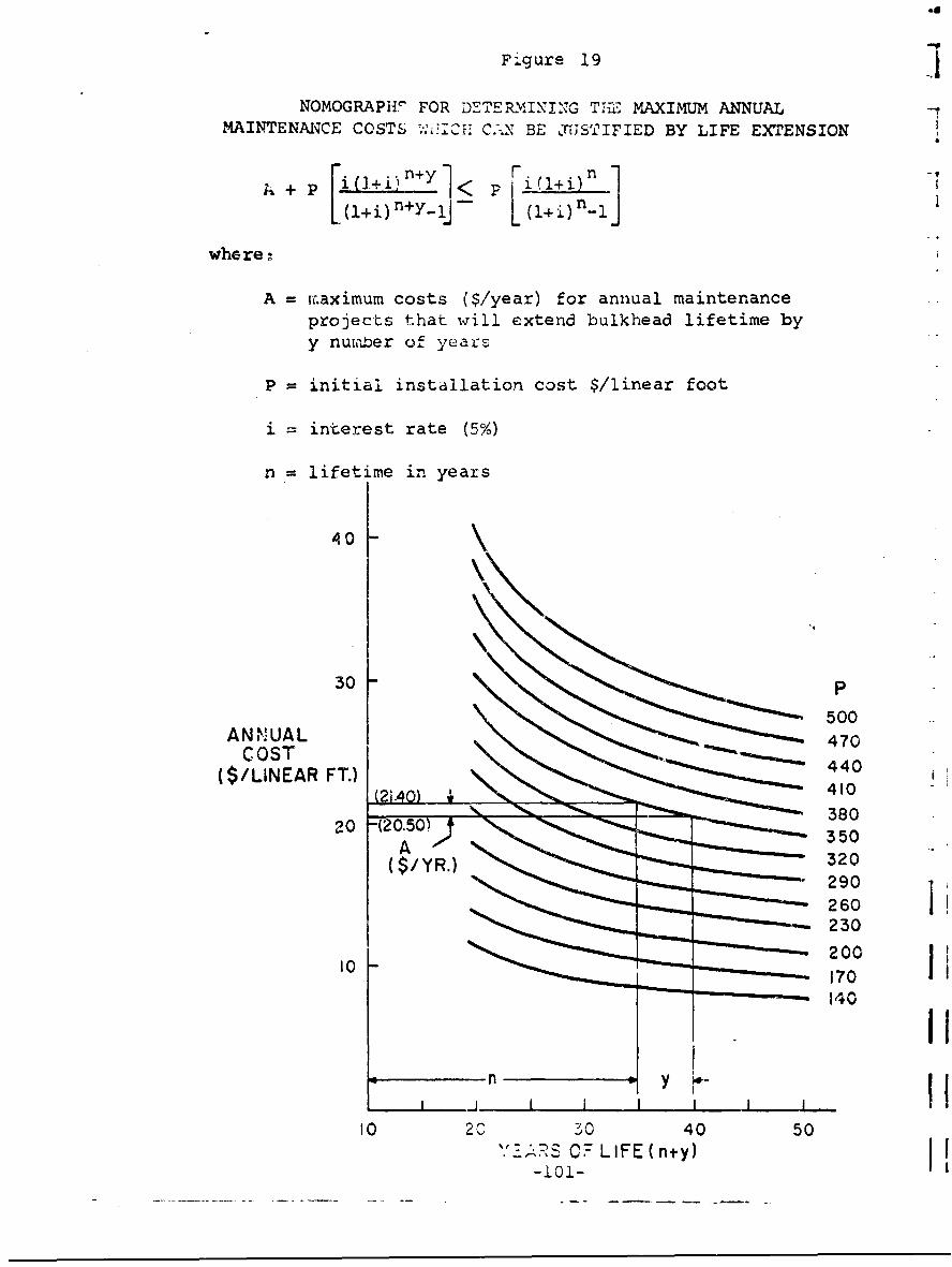
Figure 19 -
NOMOGRAPH" FOR D:-TER.IIN1'I NG TIE MAXIMUM ANNUALNAINTENA0CE COSTS -.-' '--H C-N BE POSTIFILED BY LIFE EXTENSION
whe re
A = iu.aximum costs ($/year) for annual maintenanceprojects t~hat will extend bulkhead lifetime byy number of years
P = initial installation cost $/linear foot
i = interest rate (5%)
n = lifetime in years
44
30 P
A N NU AL 470COST
($/LINEAR FT.)40(2i.40) 410-
20 -(20.50)38A 350
($/YR.) 320
230
10 200J
10 20 'jO 40 50C 7 LIE (nIy
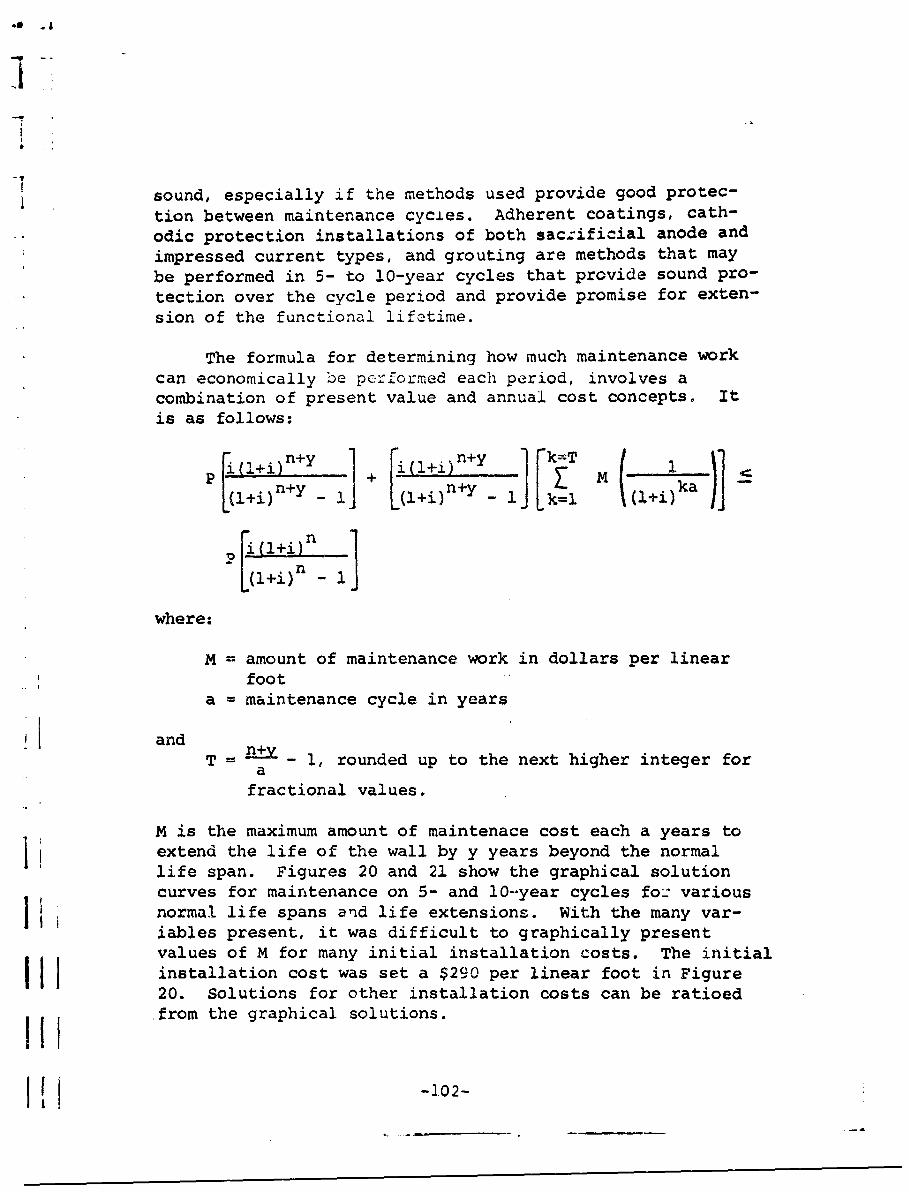
.a~i
sound, especially if the methods used provide good protec-
tion between maintenance cycies. Adherent coatings, cath-odic protection installations of both saczificial anode andimpressed current types, and grouting are methods that maybe performed in 5- to 10-year cycles that provide sound pro-tection over the cycle period and provide promise for exten-sion of the functional lifetime.
The formula for determining how much maintenance workcan economically be performed each period, involves acombination of present value and annual cost concepts. Itis as follows:
P~l+i)n+y ,~+in+y 1k=l
Pn+y n-E y ka WC
(i) l+i)n
P (l+i)n -1
where:
M = amount of maintenance work in dollars per linearfoot
a = maintenance cycle in years
andT = n+V- 1, rounded up to the next higher integer for
afractional values.
TM is the maximum amount of maintenace cost each a years toj extend the life of the wall by y years beyond the normal
life span. Figures 20 and 21 show the graphical solution
curves for maintenance on 5- and 10-year cycles fo: variousI normal life spans and life extensions. With the many var-
iables present, it was difficult to graphically presentvalues of M for many initial installation costs. The initialinstallation cost was set a $290 per linear foot in Figure20. Solutions for other installation costs can be ratioedi!i from the graphical solutions.
-1.02-
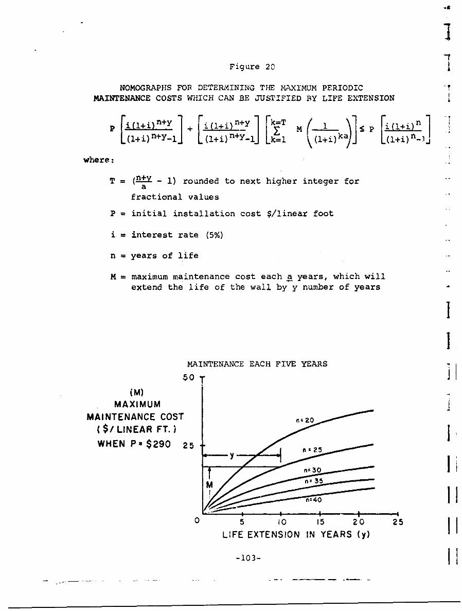
Figure 20
NOMOGRAPFIS FOR~ DETERMINING THE IN4AXIMUM PERIODIC -
M4AINTENANCE COSTS WHICH CAN BE JUSTIFIED BY LIFE EXTENSION
[::~~lJ+ [u +i+J] [k:T i,1 I
where: klik~
T = (fl~ y 1 rounded to next higher integer fora
fractional values
P = initial installation cost $/linear foot
i = interest rate (5%)
n = years of life
M = maximum maintenance cost each a years, which will
extend the life of the wall by y number of years
MAINTENANCE EACH FIVE YEARS
MAXIMUMMAINTENANCE COST 2
($/ LINEAR FT.)WHEN Ps $290 25 n2
yI
0 5 10 15 20 25 jLIFE EXTENSION IN YEARS (y)
-103-I
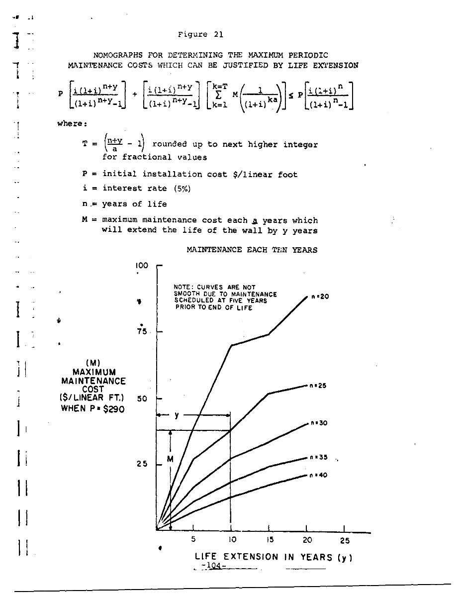
Figure 21
NOMOGRAPHS FOR DETERMINING THE MAXIMUM PERIODICMAINTENANCE COSTS WHICH CAN BE JUSTIFIED BY LIFE EXTrENSION
(l+i)n+Y I 4l(l÷)n+Y I T 1k=1 ai(i+i)n
where:
T = n+a rounded up to next higher integer
for fractional values
P = initial installation cost $/linear foot
i = interest rate (5%)
n,= years of life
M = maximum maintenance cost each . years whichwill extend the life of the wall by y years
MAINTENANCE EACH TEN YEARS
100
NOTE: CURVES ARE NOTSMOOTH DUE TO MAINTENANCE n'20SCHEDULED AT FIVE YEARSPRIOR TO END OF LIFE
1.1 75
(M)MAXIMUM
MAINTENANCE n2COST
(S/LINEAR FT.) 50WHEN Pa $290 Y
Ji I ,30
Sn z40
Ii 2
5 I0 15 20 25
LIFE EXTENSION IN YEARS (y)
a
I1
A solution to a given set of circumstances may illus-trate the feasibility of periodic maintenance. A wallthat had an initial installation cost of $290 per linearfoot is expected to have a life of 25 years. How muchmaintenance can be done each five or ten years to extendlife by ten years? The solutions are $16.90 per foot eachfive years or $38.30 per foot each ten years. The formerfigure would allow thorough cleaning and coating down tothe tidal zone. The larter figure may even allow for under-water cleaning and application of coating. There appearsto be sound justification for periodic maintenance if ade-quate life extension can be demonstrated, especially incases where design life is 25 years or less.
F. Evaluation of Repair Systems in Extending Bulkhead LAfe
As discussed previously in Section III, a sheet pile I Ibulkhead wall deteriorates unevenly. The area from slightlybelow the tidal zone to the splash zone may be approaching ifailure, while the top arid bottom of the bulkhead are stillserviceable. The steel piling driven below the mud line,which is not corroded, can be a very strong foundation foradditional construction. There are repair methods thatcan be used near the end of the normal life span of thebulkhead which use the non-corroded steel as a basic partof a life extension system. Three of these methods wereused at the NAS(NY) and will be thoroughly examined inSection IX. I!
Two approaches must be taken to the determination ofhow much can be spent on a repair system to justify addi-tional life. When the bulkhead is approaching the end oflifetime, a simple comparison can be drawn between the annualcost of the replacement system and the annual cost of the j Irepair system. The cL yes shown in Figure 22 can le usedto perform the comparison. II
When a comparison must be made earlier than the end oflitatime between replacement or repair at some future date,the formula for determining how much can be spent at theend of normal life to extend the lifetime by some period,of years is as follows: r
-105-
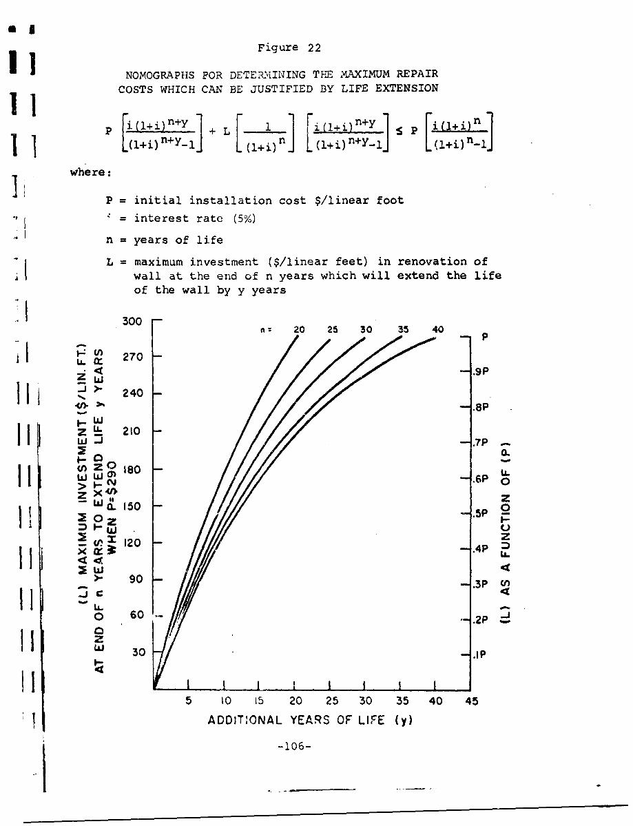
Figure 22
NOMOGRAPHS FOR DETERMINING THE MAXIMUM REPAIR11 COSTS WHICH CAN BE JUSTIFIED BY LIFE EXTENSION
11 + L (l+jfl+Y [st :1+|] Lc•in+'y-'l ( ['+,) n (,+i) n+Y-lJ L(+i) n-l
where:
P = initial installation cost $/linear foot
-= interest rate (5%)
n = years of life
L = maximum investment ($/linear feet) in renovation ofwall at the end of n years which will extend the lifeof the wall by y years
300 -~: 20 25 30 35 40
A. 0 270i < .9pii>. - 240
S.pI.-W
> .- C 0.
UZ 0 .80
z . 150 .5P
2 0z0
"II -106
90
_jC
zIIW 30 -I
5 t0 15 20 25 30 35 40 45
IADDIT.ONAL YEARS OF LIFE (y)
-106-
r +i 1l~L (l+i) - 1
where:
L = renovation investment in dollars per linear foot
and
n, y, and P are as defined previously.
A set of solutions for the maximum dollar renovation invest-ment is shown in Figure 22. The results shown in this fig-ure are based on an initial investment of P, and all valuesof L can be ratioed from the curves.
The interesting conclusions to be drawn from analysisof this data are as follows:
" Over 50-percent of the original cost can bespent for ten more years of life if theoriginal life is less than 30 years.
" The possibility appears to exist forseries of repairs each 1, to 15 years ifthe structural integrity of the sheet-steel foundation and tie--rods remains in-tact.
" One can invest a fairly significant sum(over one-third of the replacement cost)to obtain just five years additional life.
With such interesting possibilities for repair methods,there appears to be room for some imaginative engineeringat the end of the normal lifespan of a steel bulkhead.
-107"-

I|I
IIIG. Cost Considerations in the Selection of Replacement,
Maintenance, and Repair Methods
Consideration has been given to additional investmentsat the installation of a bulkhead, during its normal life-span, and at the end of normal lifespan, and there appearto be cost effective investment opportunities at all stages.These are based on life extension beyond normal expectancyand therefore presuppose a functional requirement for thewall to the end of the additional life expectancy or beyond.It should be noted in closing that the restriction to aninterest factor of 5 percent was made for expediency; theinterest factor can be varied. Raising the interest factorwill make additional investments to achieve longer life evenmore attractive, while lower interest rates will requirelonger payout periods. Also, all comparisons have beendrawn against the baseline configuration. If modificationshave been made to achieve lower annual costs, then the newfigures become the baseline against which all similar sys-tems must be measured.
-108-
VIII. BULKHEAD SYSTZMS WITHPOTENTIAL ECONOiMIC APPLICATION BY NFEC
Of the materials arid methods analyzed for applicationin bulkhead construction, maintenance, and repair, some didnot appear to offer the ,otential for additional life ia serv-ice, some did not appeir to fit t oe eivironmental requirementsin shoreline construction, and some were too costly to beadvantageous. There a>,ear to be eight material and methodsystems that fit the environmental and economic conditionsin the Eastern Division. IThese systems arc all applicableto shoreline protection of the bulkhead or sea wall type andcan'be amplified to provide foundation protection in caseswhere cost of failure is high. They are applicable in condi-tions where moderate depths of water are on the sea side ofthe wall and some earth is retained over the mean high waterlevel on the shore side. These bulkhead or sea wall systemsare not designed for heavy vertical loading or lateral loadswell in excess of normal earth pressures, but in most cases,these systems can be adapted to perform more than their basicfunction of shoreli~ne protection.a�No one system is generally superior under all designconditions. Some are better in shallow-water conditions,I some in deep-water conditions, and some in heavily usedchannels. Others cannot be used in areas where ships willbe docking. For these reasons, and to illustrate comparativeeconomic advantagcs, three shoreline profiles that aretypical of conditions met in actual experience were selectedfor comparison of alternatives (see Figure 23). In the firstprofile, the ocean floor level is in the tidal zone; in thesecond profile, the ocean floor level is slightly below meanlow water; and in the third profile, the ocean floor levelis far enough below mean low water to allow ships to dockagainst the bulkhead. In all cases, a ground level of 10 to12 feet above mean low water has been assumed.
The systems selected for detailed analysis in the threeshoreline designs can be further classified into replacement,repair, or maintenance techniques. Replacement systems eitherreplace the old sheet piling wall or functionally suppressin favor of a new svstem. The replacement systems selectedfor detailed anal%,'._ :oc.ý:
-i.09-
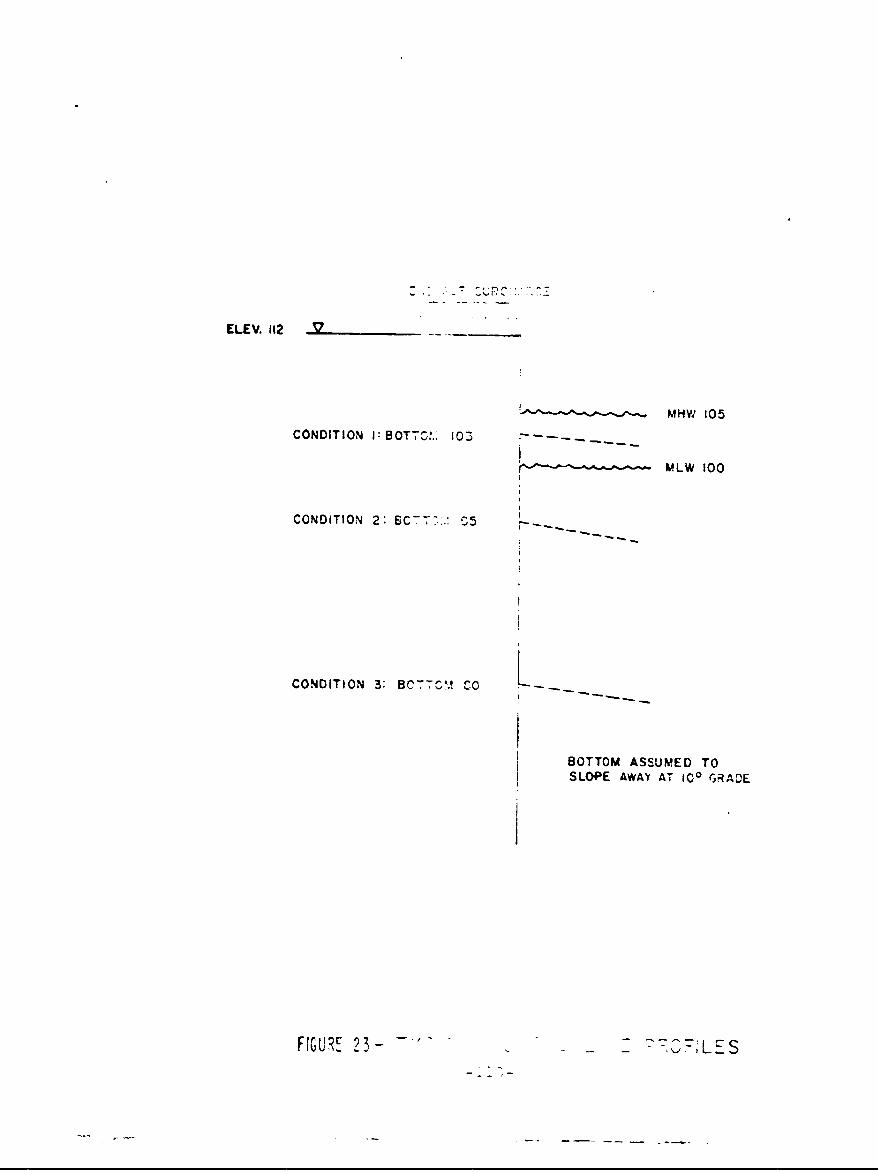
ELEV. 112 __
MHW 105
CONDITION I: BOT7T ,'.: 103 -- . . .
S MLW 00
CONDITION 2: C?2& ~
CONDITION 32 BC7TO.: -..
BOTTOM ASSUMED TOSLOPE AWAY AT 100 GRACE
FIGURE 2 - -" - - --" S
T
* special steel piling for marine applica-tions;
. carbon steel piling with initial protec-
tion; and
. rip-rap sea walls.
T:he repair systems selected are:
". concrete reinforcing on the shore side;
"* replacement of the bulkhead in the tidalzone with concrete; and
"• composite wall with timber, concrete, andsteel.
These repair systems are similar to types A, B, and C con-struction at the Naval Air Station, New York.
The mainte.iance systems selected are:
* application of coatings: and
. mortar grouting.
Direct cost comparisons can be drawn between repairsystems and between repair and replacement systems. Presum-ably, the designer has a choice of repairing or replacingwhen a bilkhead nears thie end of fuactional lifetime. Thecost of a m"-Intenance technique must be compared against thecost of another maintenance system or the alternative of nomaintenance because it does not appear to be economical toreplace or repair a bulkhead during its functional lifetime.
i
A. Replacement System - Special Stpe1 Piling forMar ine Application'
The development of a special high-strength steel formarine applications has provided the designer with a reason-able alternative to replacement with another carbon steelbulkhead. As discussed in Section III, this special steelforms a tightly adherent corrosion product that resists fur-ther rusting and scaling. This steel can be depended on toprovide longer serviceable life in the splash zone region.
Furthermore, the higher strength of this steel. meansthat a lighter section can be used for +-he same design con-dition, thus offsetting the additional cost of the specialsteel piling. A design change involving the use of lighterpiling usually results in the specification of a steel pilingwith a thinner flange and the same web section. Thus, theweb, which is perforated first in cases of advanced corro-sion, is not affected by such design changes. Special steelscost from 20 to 25 percent more than standard carbon steelbut when transportation, drivinq and installation costs areincluded, the cost disadvantaqe narrows to less than 10 per-cent. If the additional strength of the special steel per-mits a change in design to a thinner piling section, thespecial steel piling in.Lallation can actually be made at alower total cost. If, however, the same piling design isused, the special steel has to provide some additional liito be economically justifiable.
A cost comparison between special steel for marine appli-cations and carbon stc-i piling in the 3 design conditions ofFigure 23 is shown in Figure 24. It is evident that thespecial steel provides significant cost advantages if it canremain in service five or more years after a carbon steelbulkhead must be replaced. The effect of adding cathodicprotection and coating syst ±ms to both the special steel andcarbon steel bulkheads on initial installation would be toprolong the useful life of both and thereby require an evengreater advantage in the extension of useful life for the Jspecial steel.
Special steels have the advantages of slow and evencorrosion product development and greater strength. In
.1
-112-
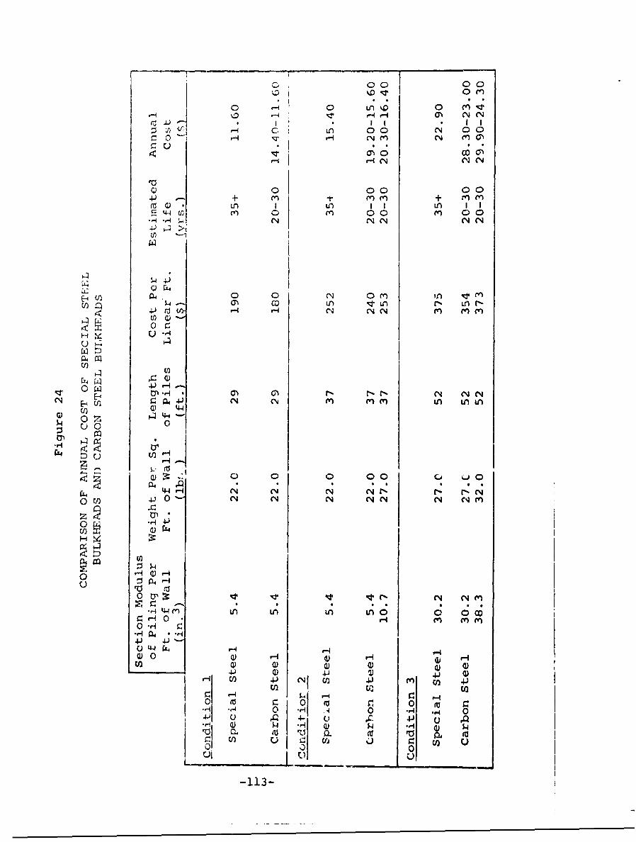
000 00
0 0 0 (ý
~JjI'I I II
V0 00 0C+0f- Ne N- + n t')
()0 00 0 00
(1) 54i
£-U) 14,0 o0 N~ 0 f Tr,
cCi F0 r-rNr
U) 44
.r4H
04 : ) P-4
-'0 00 61 i.0
C1 - ( N C4 .1 CN (r%0 U) P (N eqN (N N m~e'ri0 H
0 C14N (nm
-H 4 ( L LA C; LAO
4. 4 44
(1) 0) U)U)U) U4.) ) NJ ) 4.41m ) U)
A 4- IC 4.)0$ýi *4 H) P4 A)
£Z vCL HI j) CP
u 001 0 _ _ _ _
areas where particle abrasion is high or where vessels orflotsam are scraping against the exposed surface of thebulkhead, the corrosion product formed on the special steelscovers the exposed steel area with a dense impermeable oxidein contrast to carbon steel, which when scraped may developa weak area which can'corrode at an increasing rate. Theadded strength means that for a similar design the safetymargin in special steel is far greater and that the samecross-section of uncofroc:c( metal can be relied on to sup-port additional stress loading. Balanced against these con-siderations is the additional cost of the special steel whichmay require a longer payout period.
When the cost of failure of a bulkhead is high, whenthe accessibility to a bulkhead is limited, or when mainte-nance and repair costs are high, the advantages gained byusing special steels are emphasized. When the mission lifeis certain to be long, special steels are also desirable.When mission lifetime is uncertain, when maintenance iseasily accessible and low in cost, and when the cost offailure is low, special steels may not compare favorablywith standard carbon steel.
-114-
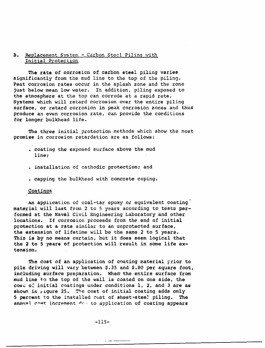
B. Replacement System - Carbon Steel Piling withInitial Protection
The rate of corrosicn of carbon steel piling variessignificantly from the mud line to the top of the piling.Peat corrosion rates occur in the splash zone and the zonejust below mean low water. In addition, piling exposed tothe atmosphere at the top can corrode at a rapid rate.Systems which will retard corrosion over the entire pilingsurface, or retard corrosion in peak corrosion zones and thusproduce an even corrosion rate, can provide the conditionsfor longer bulkhead life.
The three initial protection methods which show the mostpromise in corrosion retardation are as follows:
"* coating the exposed surface above the mud
line;
"• installation of cathodic protection; and
". capping the bulkhead with concrete coping.
Coatings
An appiication of coal-tar epoxy or equivalent coatingmaterial will last fron 2 to 5 years according to tests per-formed at the Naval Civil Engineering Laboratory and otherlocations. If corrosion proceeds from the end of initialprotection at a rate similar to an unprotected surface,the extension of lifetime will be the same 2 to 5 years.This is by no means certain, but it does seem logical thatthe 2 to 5 years of protection williresult in some life ex-tension.
The cost of an application of coating material prior topile driving will vary between $.35 and $.80 per square foot,including surface preparation. When the entire surface frommud line to the top of the wall is coated on one side, thecose of initial coatings under conditions 1, 2, and 3 are asshown in rigure 25. The cost of initial coating adds only5 percent to the installed cost of sheet-steel piling. TheannuAl. c-,t increment .-b to application of coating appears
-115-

0 0o00c 100
r-40. -I -4r- -q -Ir--i F-4 H- qr-i 1 (N N N CNN
000 00 000 00 000 00
-I P- r-- ON r-4 0N oCN (1 NN n N
*) (v L 0 0 0 0 L" 0 0 0 0 Ln QO 0 044 (w w( I () (nN (w) ( M cnN
C N N N N CN N CNLA NLNO
z ,Ir4N NNCNN 0 04 rn LAn N (n mcoC
H
~E-4
0 .04-t
4.1 r. 000 0 c00 0 00000 r4O 0 0 % 0000
U 4. -4N C N r-4 N NO H 04
rzQ 4.I 1IAi
Ln 0 44 L
N- toE- H 0
Nt-, 44 0
0 VO 0- (N 0 N
o 44 rj 0U)) 0 U /
o0 tn0__ __ _ __ __ _ __ __ _ __ __ _ _ __ _ __ __ _ __ __ ___ __ _ __ __ _ __ __ _
-11 - - -_ ___ __ __-A_
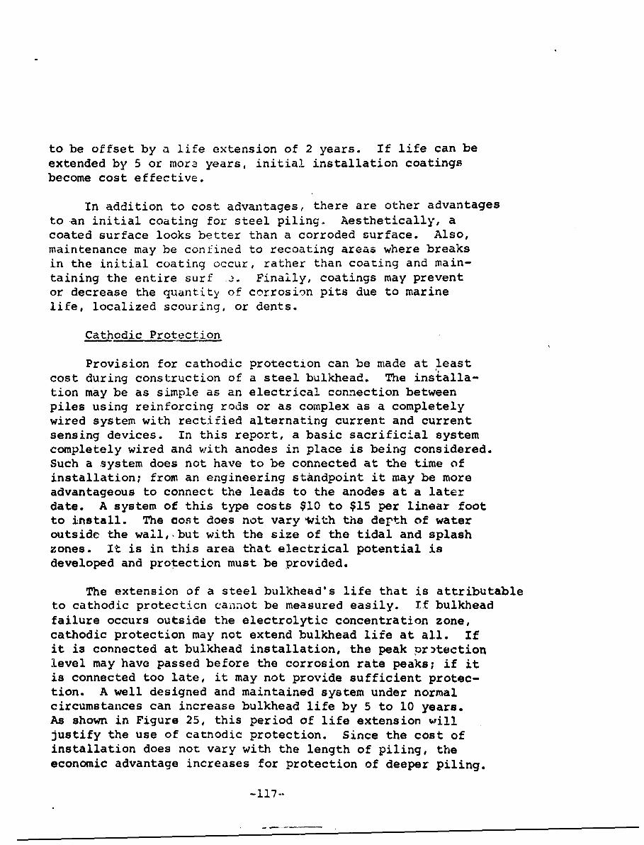
to be offset by a life extension of 2 years. If life can beextended by 5 or mora years, initial installation coatingsbecome cost effective.
In addition to cost advantages, there are other advantagesto an initial coating for steel piling. Aesthetically, acoated surface looks better than a corroded surface. Also,maintenance may be confined to recoating areas where breaksin the initial coating occur, rather than coating and main-taining the entire surf ý. Finally, coatings may preventor decrease the quantity of corrosion pits due to marinelife, localized scouring, or dents.
Cathodic Protection
Provision for cathodic protection can be made at leastcost during construction of a steel bulkhead. The installa-tion may be as simple as an electrical connection betweenpiles using reinforcing rods or as complex as a completelywired system with rectified alternating current and currentsensing devices. In this report, a basic sacrificial systemcompletely wired and with anodes in place is being considered.Such a system does not have to be connected at the time ofinstallation; from an engineering standpoint it may be moreadvantageous to connect the leads to the anodes at a laterdate. A system of this type costs $10 to $15 per linear footto install. The cost does not vary with the depth of wateroutside the wall, but with the size of the tidal and splashzones. It is in this area that electrical potential isdeveloped and protection must be provided.
The extension of a steel bulkhead's life that is attributableto cathodic protection cannot be measured easily. If bulkheadfailure occurs outside the electrolytic concentration zone,cathodic protection may not extend bulkhead life at all. Ifit is connected at bulkhead installation, the peak pr)tectionlevel may have passed before the corrosion rate peaks; if itis connected too late, it may not provide sufficient protec-tion. A well designed and maintained system under normalcircumstances can increase bulkhead life by 5 to 10 years.As shown in Figure 25, this period of life extension willjustify the use of catnodic protection. Since the cost ofinstallation does not vary with the length of piling, theeconomic advantage increases for protection of deeper piling.
-117--
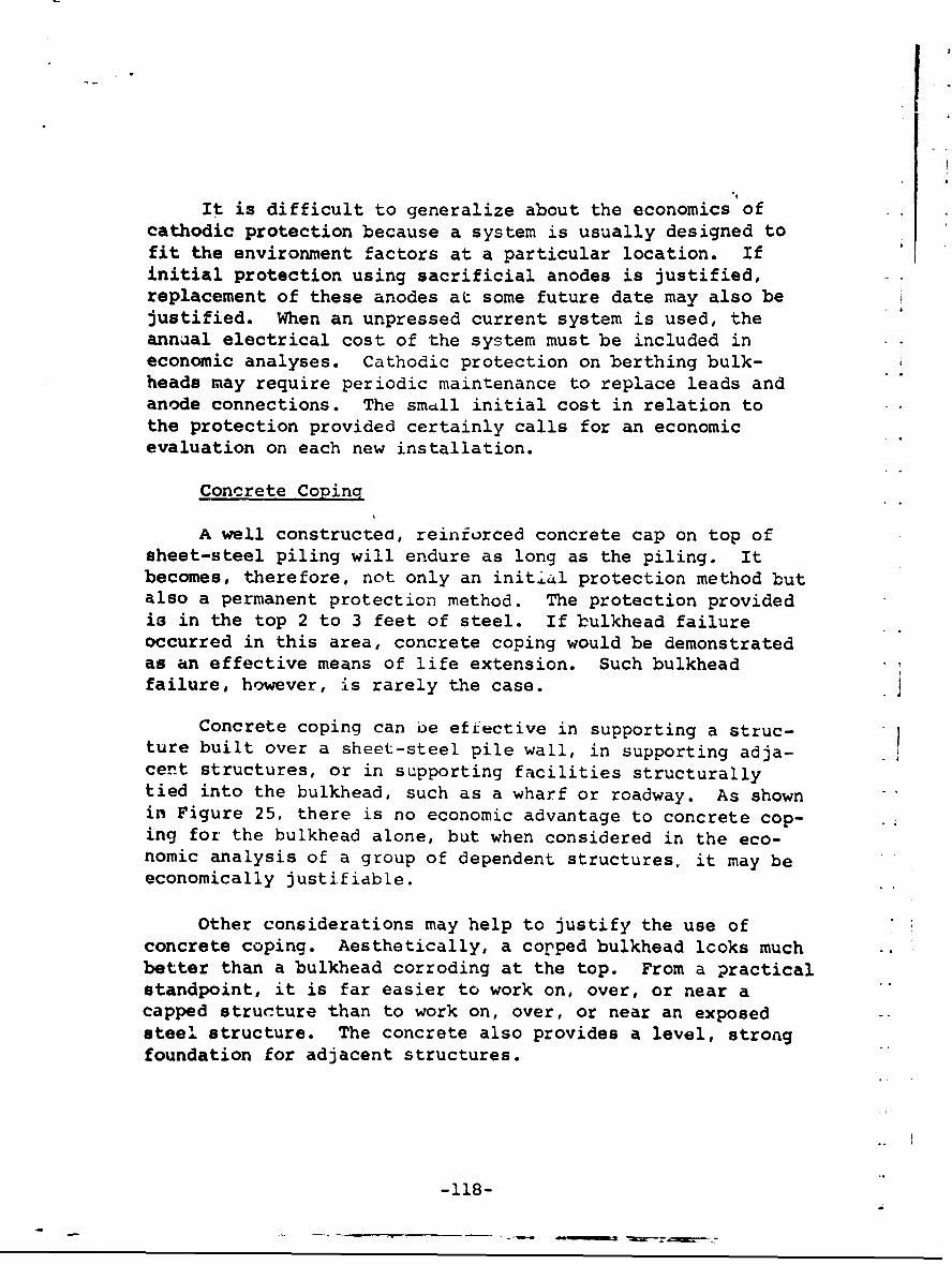
It is difficult to generalize about the economics ofcathodic protection because a system is usually designed tofit the environment factors at a particular location. Ifinitial protection using sacrificial anodes is justified,replacement of these anodes at some future date may also bejustified. When an unpressed current system is used, theannual electrical cost of the system must be included ineconomic analyses. Cathodic protection on berthing bulk-heads may require periodic maintenance to replace leads andanode connections. The smdll initial cost in relation tothe protection provided certainly calls for an economicevaluation on each new installation.
Concrete Coping
A well constructed, reinforced concrete cap on top ofsheet-steel piling will endure as long as the piling. Itbecomes, therefore, not only an initial protection method butalso a permanent protection method. The protection providedis in the top 2 to 3 feet of steel. If bulkhead failureoccurred in this area, concrete coping would be demonstratedas an effective means of life extension. Such bulkheadfailure, however, is rarely the case.
Concrete coping can be effective in supporting a struc-ture built over a sheet-steel pile wall, in supporting adja-cent structures, or in supporting facilities structurallytied into the bulkhead, such as a wharf or roadway. As shownin Figure 25, there is no economic advantage to concrete cop-ing for the bulkhead alone, but when considered in the eco-nomic analysis of a group of dependent structures, it may beeconomically justifiable.
Other considerations may help to justify the use ofconcrete coping. Aesthetically, a copped bulkhead looks muchbetter than a bulkhead corroding at the top. From a practicalstandpoint, it is far easier to work on, over, or near acapped structure than to work on, over, or near an exposed -
steel structure. The concrete also provides a level, strongfoundation for adjacent structures.
-118-
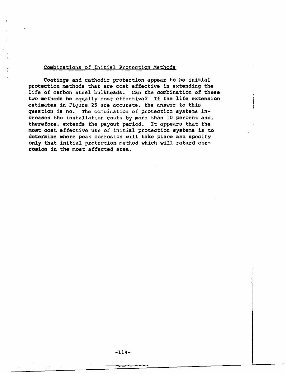
Combinations of Initial Protection Methods
Coatings and cathodic protection appear to be initialprotection methods that are cost effective in extending thelife of carbon steel bulkheads. Can the combination of thesetwo methods be equally cost effective? If the life extensionestimates in Figure 25 are accurate, the answer to thisquestion is no. The combination of protection systems in-creases the installation costs by more than 10 percent and,therefore, extends the payout period. It appears that themost cost effective use of initial protection systems is todetermine where peak corrosion will take place and specifyonly that initial protection method which will retard cor-rosion in the most affected area.
-119-

7
C. Replacement System- Rip-Rap Sea Walls
Rip-rap bulk wall systems are one of the oldest andmost effective means of shore stabilization. The bulk wallis constructed in layers of progressively lager stones 1from a point sufficiently below the mean low water level toprevent scour, up to the grade line on the shore side. Thecover layer consists of large stones several hundred poundsin weight, which will resist the heaviest surf.
Some basic conditions must be met prior to the instal-lation of rip-rap. The ocean floor under the rip-rap mustbe capable of supporting the heavy burden of the wall andshould slope away gradually. Otherwise, the installationcosts of the wall will increase geometrically, and stabil-ity of the wall may ba more difficult to maintain. Rip-rapwalls are not suitable for berthing of vessels, so thereshould be no need for access to the shore in the vicinityof the rip-rap.
The cost of rip-rap installation depends on these fac-tors:
"cost of supporting bulkhead for shoreline;
" amount of stone used;
" availability of large stone;
" distance from shore to toe of wall; and
" accessibility to wall for heavy equipment.
With a supporting wall in place that is strong enough to sup- Jport the additional lateral loading of the heavy equipment re-quired to place rip-rap and with large stone available, rip-rap can be placed for $10 to $15 per cubic yard. As shown inFigure 26, rip-rap would be a very economical ma erial fordesign condition 1. The annual cost of the rip-rap instal-lation is only 15 to 20 percent of the annual cost of a re-placement carbon steel bulkhead. A rip-rap bulk wall alsoappears to be economical for design condition 2. Installa-tion costs may increase beyond the estimate in design condi- jtion 2 if the ocean bottom has to be rrepared to support theweight of the wall or if proper placement becomes difficultat increasing depths. At some point between condition 2 and jcondition 3, rip-rap installation loses any annual cost ad-vantage. -120-

(a 4-to
(N goN
r~4N mN~
0 00rX >o 0
44 0 00 00 0
041 c
H 44 0> 00En? V- N 0 0
R> 4 ~ C-44 N(' V
0 0
P4
00
c C'U4~to 41 o
C'.C
Mv 0~ jw
r-4 4
-4 4 4
0041-4
-4 tz.4 m-4fI ;a w
0 C11 0
u r,,
-121-

The advantages of rip-rap bulk walls are low cost in-stallation and permanency. By using an existing wall as thefacing, rip-rap can be placed quickly and inexpensively downto depths 30 to 12 feet below mean low water level. Someperiodic maintenance, consisting of replacing some stone andfilling void spaces to prevent wash-out, will produce apermanent wall.
Unfortunately, there are several limitations to the useof rip-rap. It cannot be used:
"• where access to the beach from the sea isrequired;
"* where the mud line slopes off sharply; or
. near a channel.
In addition, it becomes uneconomical:in deep water, and itspermanency becomes a disadvantage if replacement becomesnecessary or construction is scheduled along the shore line.Unlike steel piling, the removal costs for rip-rap are high.
In summary, rip-rap is a very economical type of shorestructure where shore protection is the major requirement.If berthing of ships is necessary or contemplated or if the -,
function of the shore structure may change, it may not besuitable.
4•
1b
*1I
-122- _ _
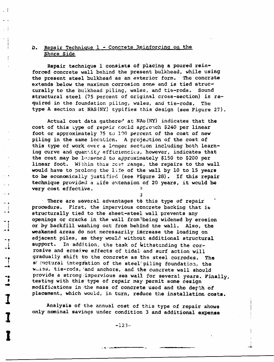
D. Repair Technique 1 - Concrete Reinforcing on theShore Side
Repair technique 1 consists of placing a poured rein-forced concrete wall behind the present bulkhead, while usingthe present steel bulkhead as an exterior form. The concrateextends below the maximum corrosion zone and is tied struc-turally to the bulkhead piling, wales, and tie-rods. Soundstructural steel (75 percent of original cross-section) is re-quired in the foundation piling, wales, and tie-rods. Thetype A section at NAS(NY) typifies this design (see Figure 27).
Actual cost data gatheree at NA5(NY) indicates that thecost of this type of repair could ap.conch $240 per linearfoot or approximately 75 to 100 percent of the cost of newpiling in the same locaticn. A projection of the cost ofthis type of wor. over a longer seci.Lon including both learn-ing curve and quant.iti efficienciý:.s, however, indicates thatthe cost may be lozsened to approximately $150 to $200 perlinear foot. Within this zc3t range, the repairs to the wallwould have to prolong the life of the wall by 10 to 15 yearsto be economically justified (see Figure 28). If this repairtechnique provided a life extension of 20 years, it would bevery cost effective.
There are several advantages t& this type of repairprocedure. First, the impervious concrete backing that ihstructurally tied to the sheet-steel wall prevents anyopenings or cracks in the wall from~being widened by erosionor by backfill washing out from behind the wall. Also, theweakened areas do not necessarily increase the loading onadjacent piles, as they would withoUt additional structuralsupport. In addition. the task of tithstanding the cor-"rosive and erosive effects of tidal and surf action willgradually shift to the concrete as the steel corrodes. Thesf -lictural integtration of the steel.1piling foundation, thew~s tie-rods, land anchors, and the concrete wall shouldprovide a strong impervious sea wall for several years. Finally,
"6 testing with this type of repair may permit some designmodifications in the mass of concrete used and the derth ofplacement, which would, in turn, reduce the installation costs.
Analysis of the annual cost of this type of repair showsonly nominal savings under condition 3 and additional expense
-123-'
I
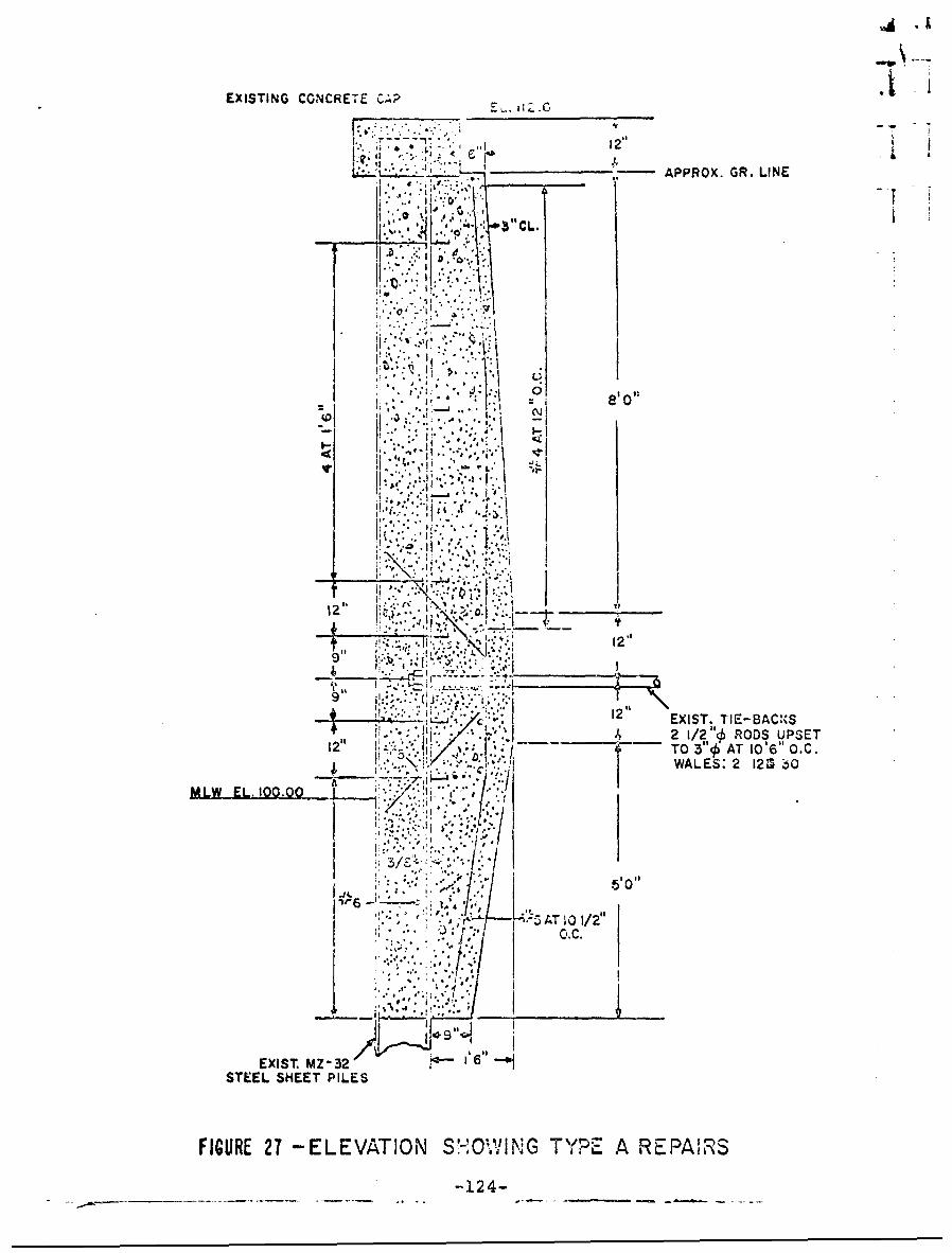
EXISTING CONCRETE C.P ."
* '~.12"I, '. '. • " " : I• -
;i .. ". '. ., . , I• • -APPROX. GR. LIE
*8 1
**I *'.. .11,
- .. ;. V ..
(08 0
t e
*... ;! t
It
9~ T
0-1112'
c i2'IEXIST. "IE-BACI%"S______ 2 1/2"o RODS UPSET
I ,i 3 Ji I . .-
.:..N~ ~WALES: 2 120 60
MIW EL. 100.00 ~
,°•/ - " . - I
! ,w '"' ,,50
w6 ~ ~ _, AT i'C0' 1~AT / 2 "
* *. ,1" , I I
'.* ,,' "..*l , de o
STEEL SHEET PILES
FIGURE 27 -ELEVATION S4'0~%1'N;G T A RCEPAIRiS
-124-
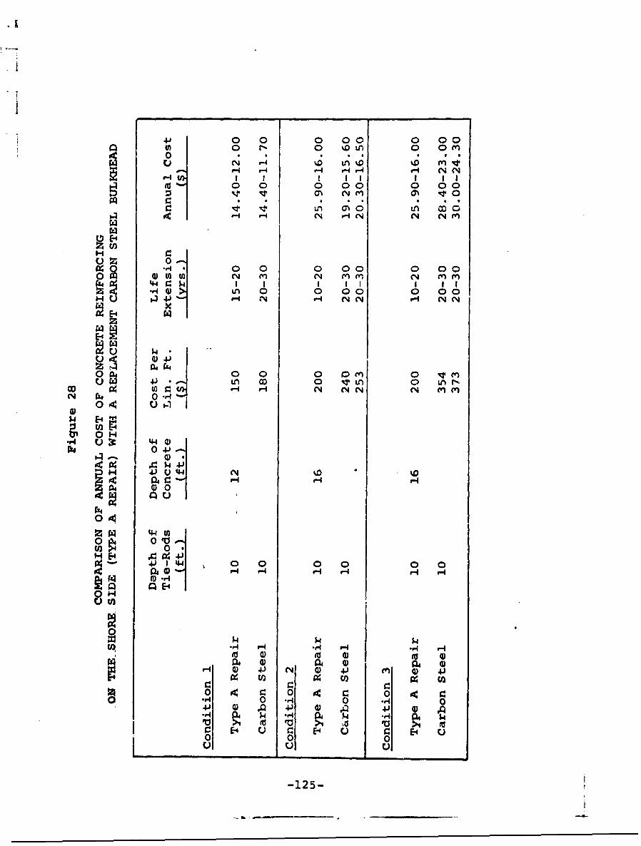
41' 0 0 0 00 0 000 1*- 0 %.D n 0 0 m
l) N P4 'o L0 %DI m v
0 0 0 00 0 00
H- r- N H-iN C1 N
z 0.40 0 0 0 00 0 00
z 4):ý-in 0 0 00 0 041 r- C4 NC H N N
~ 04 4
O Ij 0 n 0 0 1 om 0 Lr"
OD Pi. to H or- N N.N N (n (n
14 E-4& m.
00[~ ~ 4-) * '
$4V
04 0 00
0N
0~ 0 to
1 40 0 0 0 0 0jai (D r 4 ) r- 0- r4. r- 0 4Qj r4
_ _ _ _ _ Q_ _ P0
-15
$414$

I
Iunder conditions 1 and 2. Unless the cost of installationcan be markedly reduced or the life extension shown to bebeyond estimates, this type of repair may have only marginalapplication. There is uncertainty about the design life ofthis technique, because there is no evidence of the effectof freesing and thawing cycles on this type of wall with asteel-concrete interface, or how well the concrete reinforc-inq, which will be partially exposed when the steel pilingis eroded, can endure.
This type of repair is best suited to situations in whichnew piles cannot easily be driven, or the bulkhead to be re-placed cannot easily be removed, but in which forming andpouring of concrete is possible. A sheet-steel pile bulkheadcovered by a wharf or dock may be repaired using this tech-nique. Similarly, a short section of piling wall can berepaired by this method without the iuse of expensive equip-ment.
11-126-
E. Repair Technique 2 - Concrete Replacement of Stcelin the Tidal Zone
Repair technique 2 utilizes the existing sheet-steelpiling as a foundation for a poured, reinforced concretewall that extends from below the tidal zone to the shorelineelevation. The existing steel structure is cut off at themean water level line or slightly below. Then, forms andreinforcing are placed on either side of the old wall, andconcrete is poured down to 2 or more feet below the meanlow water level. The concrete is tied structurally to theremaining bulkhead piling, wales, and tie-rods. The type Bsection at NAS(NY) typif:= this method (see Figure 29).
Experience with this type of construction at NAS(NY)showed a cost per linear foot of $268 in the test section(21 feet). With longer installations, the cost per linearfoot should decrease to $175 to $250, even when the repairsare made to a wall in deep water. Life extension necessaryto justify this cost would be in the 15- to 25-year range(see Figure 30). This life extension, which is more thanthat required in repair technique i,'can be expected becausethe repaired section will have a smooth concrete facing withnr reinforcing exposed. With little overturning moment, suchas in condition 1, the repai::*-ci wall should last as long asa poured concrete wall. In conditions 2 and 3, where addi-tionel. weight at the top of the wall may add to the over-turning moment, the structural condition of the steel pilingbelow water will probably determine the life of the repairedwall. In all three conditions, a life expectancy equal tothe original bulkhead may not be unreasonable.
The advantages of this type of repair are generally thoseof repair technique 1, with the exception that the concreteimmediately assumes the burden of withstanding the environ-mental conditions. The structure will have a continuousfinished face that would be architecturally pleasing andsuited for berthing of small vessels. There is also thepossibility of design modifications to reduce the cost ofinstallation.
Unfortunately, the annual cost of this repair techniquein conditions 1 and 2 compares marginally with a replacement
-127-
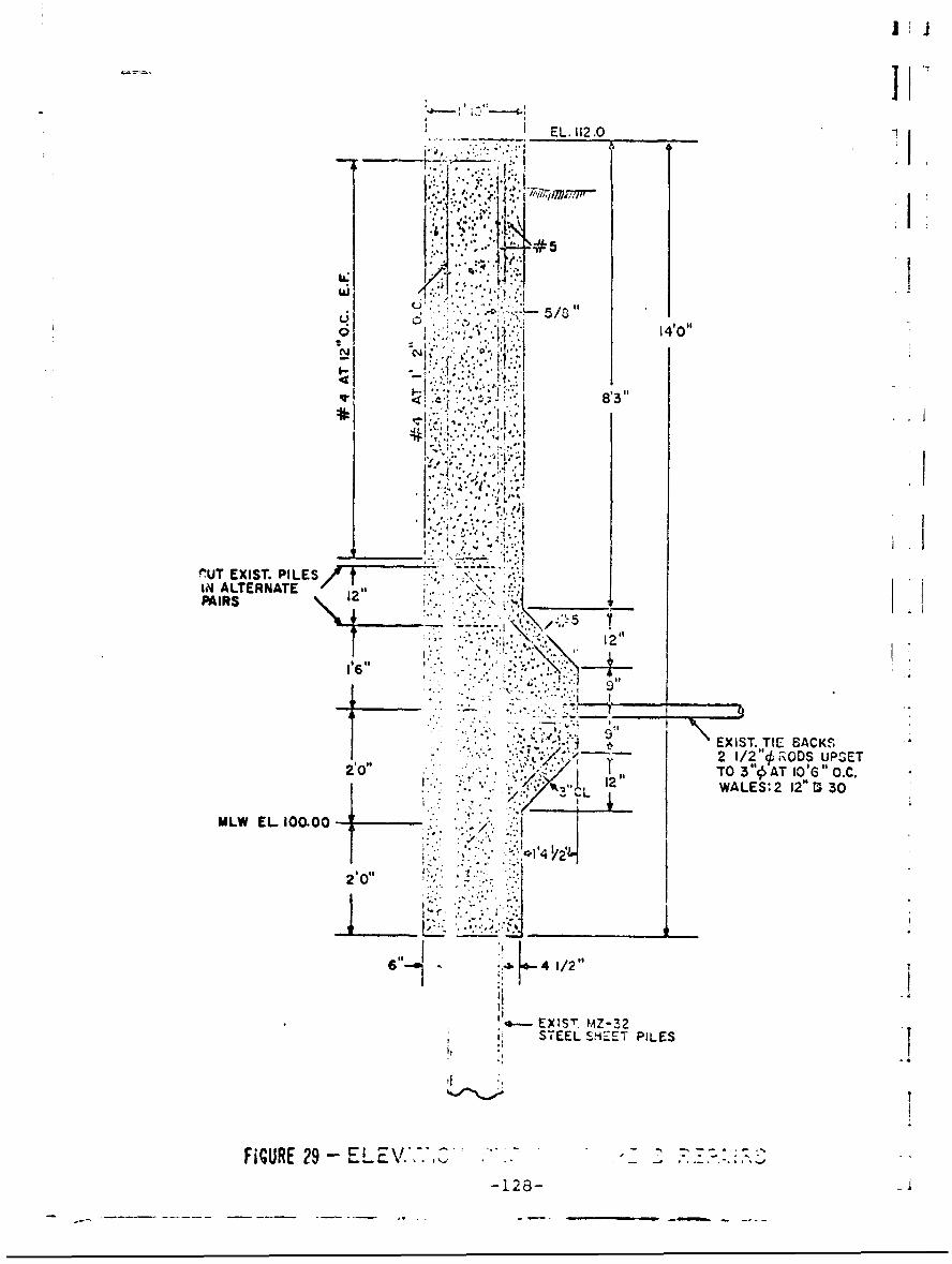
I EL. 112 .0
uki5 /0
140O
16
NUT EXIST. PILES .IN ALTERNATE 1FAIRS 12____
EXIST. TIE BACKS/2 ~ -2 1/2'4RODS UPSET20"I TO 3 "o AT 10% " 0.C./ ~ 12"WALES: 2 12" M 30/L
MLW EL 1~a000/
01420"
6 4 1/2"
EXIST 'I' MZ-33STEEL SHEET PILES
FiGURE 29 -EL .7*-128-
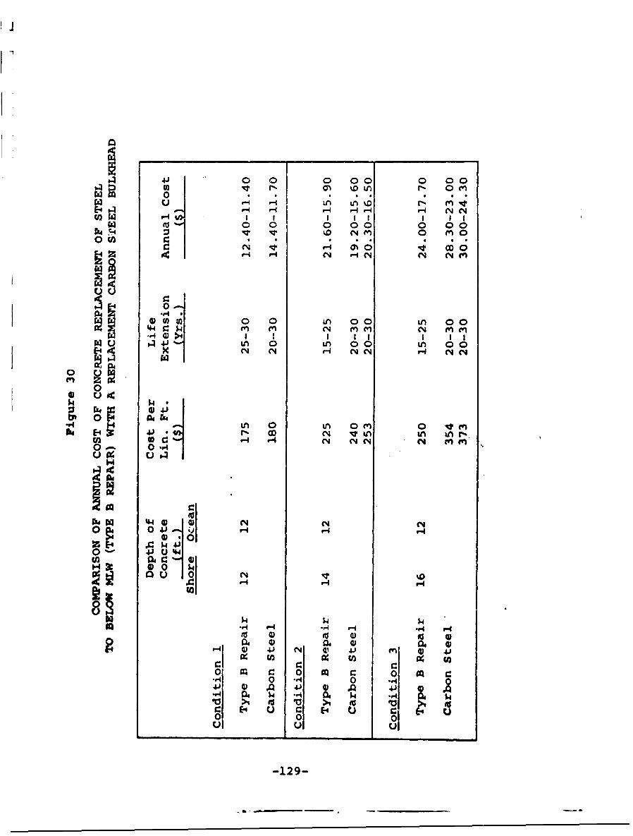
I oJ o 0 00 0 00
0' IOU 00 00~V4 I, qwII0 0 (r -4 r- 4 N- ~ I
(z ) m t 0 0 0n 00 0n 00Ij 'n 0 0 0 (n 0 ('0
x- N- f-4 H(% NC4 ~N C
00.54
""4 0n 0 n 0 m' 0 0qtf
0 0r
0az 0 V Lfl 0i0 J'U) ~ 4 Nd f- Hc l
0 04
O ~ a 04 N-vH
11 4 54
r- 0 N C 4J M ~) 4'
0 9Q~ 0 m.r4 0 .,40 r
0w 4 $4 2 . , S4 2.4 554~ . U Cf>% ig V >1 fu
0 00
-129-
wall of carbon steel (see Figure 30). Unless the cost perlinear foot can be reduced considerably, the application ofthis technique in shallow water is limited. In condition 3there appears to be a favorable cost comparison between thisrepair technique and replacement with carbon steel.
Repair technique 2 results in a poured concrete wall inand above the tidal zone, which is structurally tied to thesheet-steel piling foundation. Since the top of the steelsection is removed, the finished wall will be an attractivesea wall suitable for berthing purposes. This techniquedbes not appear to be economical for use in shallow water,but it may be used in bulkheads adjacent to channels or inbulkheads that are part of, or adjacent to, wharfs.
-130-
*1
.. .-
F. Repair Technique 3 - Composite Wall with Timber,Concrete. •nd Steel
Repair technique 3 results in a composite wall withstructurally integrated layers of timber, concrete, and steel.A timber-sheeting wall is driven into the mud line a minimumdistance of 6 inches from the existing sheet-steel bulkhead.The timber and steel walls are bolted together and reinforc-ing for the concrete is placed between the two walls. Thespace between the timber and steel is filled with concre..e.This technique is similar to the type C construction atNAS(NY). At the Naval Air Station, however, the timber wasdriven next to the wall, and only the cells formed by thepiling were filled with concrete.
The cost of this type of repair will vary with the lengthof timber sheeting that is driven and the depth of the pouredconcrete. The cost to drive creosoted timber piling up to40 feet in length is approximately $400 to $500 per 1,000board feet. Concrete cast-in-place costs $15 to $2C percubic yard. Using these cost estimates as a guide, the costof repair technique 3 in the three conditions is estimatedat $69 per linear foot, $156 per linear foot, and $3A3 perl1-ear foot. (Type C c nstruction at NAS(NY) cost $68 perlinear foot in an area similar to condition 2.)
Not only do costs increase sharply in deep water, butthe results are less reliable. Concrete can be cast intoshallow water with good results, but the results are at bestuncertain when concrete must be cast into deep water. Acoffer dam should be used in deep water, which sharply in-creases the cost. Primarily for this reason, the life exten-sion estimates should be shorter in deep water conditions.
Figure 31 shows the annual cost estimates for repairtechnique 3 and the comparable annual cost of a repla:ementcarbon steel bulkhead. As shown, repair technique 3 appearsto be very cost effective in tidal installations, marginallycost effective in shallow water, and cost ineffective indeep water.
There are several advantages to thIs type of repair thatcannot be measured econcomically. The timber facing is
-131-
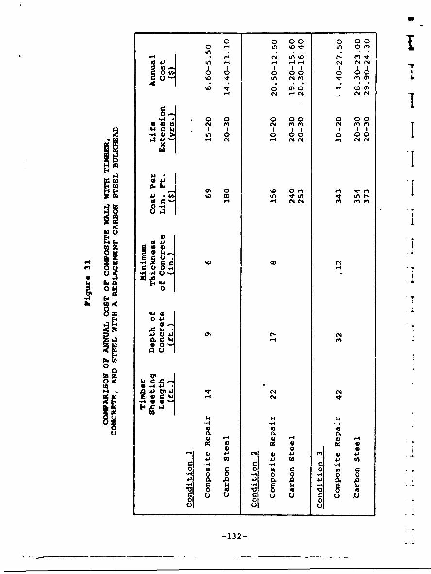
0 0 00 0 00t0 in& %0 NT i 0 (
I I II I II1:0t 00000 0 00
0"4. . 0 0 0 00 0 0040 M N (InE M N (nMc I I I I 1 10 > Lf 0 0 00 0 00
14J
II%.0 OD inV-4Lnr£0~~~ V.44 .(N
V4 C O
tj V -A U
0 0
0 V
-IV2
resilient and can withstand shock and alternate wetting anddrying better than concrete or steel. The concrete ispartially protected from freezing and thawing cycles andin turn protects the previously exposed surface of the steel.The timber exterior is a good bulkhead material for use whereships are berthing. The concrete extends down to the siltline and does not contribute to the overturning moment ofthe wall as it may in repair techniques 1 and 2.
A major disadvantage of this repair technique is thatit is of questionable value in deep water. Also, the con-crete and timber facing are structurally tied to the steelbulkhead only and are not tied to the anchoring system.
-133-
.1
G. Maintenance Technique 1 - Coatinq Application
Tests conducted by the U.S. Naval Civil EngineeringLaboratory and the Port of New York Authority demonstratethat an impermeable layer of good coating material can beapplied both before installation and while the piling is inservice. Tho test resuits also indicate that most coatingswill break dc¢w in 2 to 5 years in service but that thefailure condition is iccalized. With these results in mind,it appears that periodic Maintenance to maintain an imperme-able coating of corrosion-proof material can extend lifewithin justifiable cost limitations.
Vie major limitation to wide usage of protectivecoatings is the relatively high cost of in situ application.As discussed in Section IV, all coatings must be placed overa clean adherent surface. Before piling is driven, thelengths of piling can be peened or sandblasted to white metaland the coatina can be brushed on easily. Once the pile isdriven, however, coating the exterior surface is difficult.Mhe pil- surface is relatively inaccessible, usually wet ordamp, and it may be covered with scale or vegetation. Theblasting, cleaning, and application in and above the tidalzone can be done from a platform hung over the side of thebulkhead. Work, under the tidal zone must be done by divers.
The vost of Coating applications prior to installationvaries from $.35 to $.80 per square foot. The cost of coat- --
ing applications on in situ piling varies from $1.00 to $2.00per square foot in the tidal zone and from $3.50 to $8.00per square foot under water. A complete coating applicationfor a bulkhead with 6 to 12 feet of tidal and splash zonesand 2 to 3 feet of surface in the active electrolytic zonemay cost $30.00 to $50.00 per linear foot.
Figure 32 indicates the conditions necessary to optimizeannual savings through periodic applications of coatings.Coatings applied on short intervals,, such as 2 years, mayprovide additional bulkhead life, but they will not be costeffective, even if a small area is treated. With 5-yearintervals between coating applications, this type of periodicmaintenance may be cost effective, especially if small areas(5 to 10 square feet per linear foot: of wall) are treated.
-134-
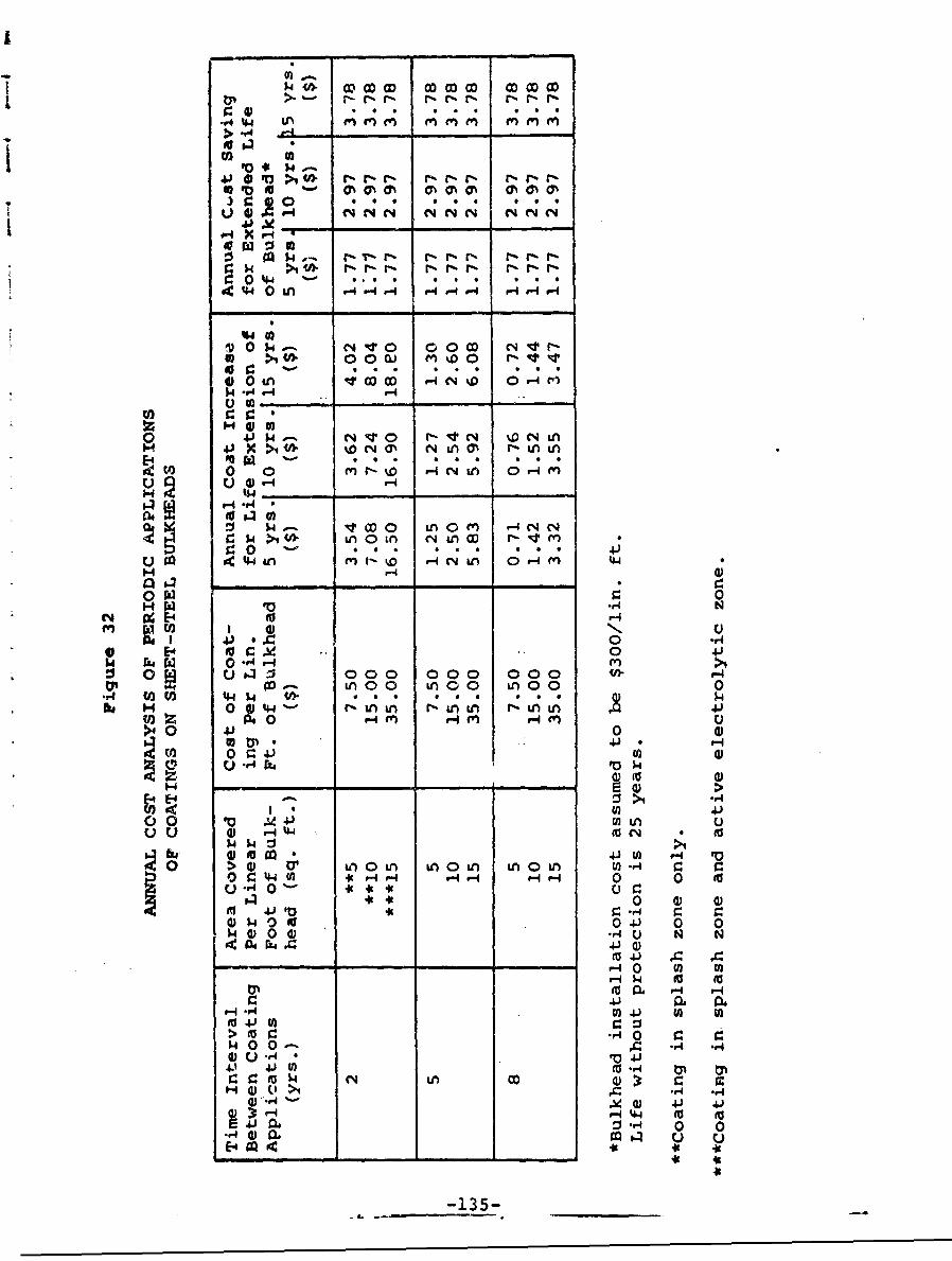
.r4 _4_ M e e 1
.0 M
#- x -
$4 >1C - T-r-g rrl-rlý r% I- r-
0 44
>1 0 0 M%0 0 r- V-0in ItI~ OD~ CO r4N 0 .qJ4.r
r-4
0 C4~- V r e 4 % N~( ~ 0V 4xifl %0 C4 a' N Ln ON r- in 0
01 0 fO -4'L 0H )
UH 5-#4__
H r-4 4
fn a to *1-4I VU 0
SE-4 t r.J -. 0 .4-)1.4 rz, W 0 -4H (n) >4
:0;: C)000 000 000 r-4irM ý n0 0 in 00 un 0o 0
.r 02C ) 4.~ 4 "" g Lý 690 0 0 g V; 4, $4)to . H4 00' r-tnu M uU ru-f M.
01 0J0e' 41
U) 41
41U) P 4 to
CJU 0 r.J4jCJ * E
fn 41 H0 4
0H He- 0 0 41 0 0UM 0 0 0 4q (4,
04 r04J 0 0
(a1 41
$400-r- -150II-034 it Q, r4 -
r. ~ I 4J--1
I
Applications of coatings over the entire tidal and active IelectrolyLtc zones can be justified when done at 8-yearintervals. 1
To determine the best policy for coating applications,it is necessary to integrate the functional life of the coat-ing in the design environment and the cost effectivenessof periodic applications. If used in combination withcathodic protection, coating applications may be limited tothe tidal and splash zones. Once again, the effectivenessof corrosion retardation and the cost effectiveness of peri-"eic coating must be compared to increased bulkhead lifeto determine the best course of action.
There are other advantages to coating systems for main-tenance work. They do not change the basic shape or appear-anee of the bulkhead. The work can be done sporadically bya small crew under Public Works Office administration. Tech-nical advances can be iasily incorporated. Of greatestimportance is the fact that a good coating application canalmost completely arrest corrosion during the period ofmaximum effectiveness. A
7
I16
-136-

H. Maintenance Technicue 2 - Grouting and ConcretePatching
Properly installed, sheet-steel piling is only semi-impervious to penetration by sea water. After considerableexposure, penetration increases due to puncture, bolt Holes,and joir~ts that have loosened, and corrosion-induced holes.When holes and leaks occur, the corrosion and erosionprocesses increase because fill is washed out from behind thewall and corrosion proceeds on both surfaces of the wall.When holes and leaks occur, proper sealing and/or soilstabilization to prevent sea water from washing out backfillcan result in longer wall life. Two related methods that maybe used to seal leaks and stabilize soil are cementitiousgrouting and concrete patching. These methods are comple-mentary, with the method selected for use based on the typeof hole and the soil conditions.
Grouting is the process of forcing cementitious materialsinto the earth in an effort to bind the soil into a hard mass.A pipe is driven down into the soil and grout, under pressure,is forced down the pipe. The grout will seek out the voidsand least-compacted soil and will eventually bond soilparticles together. In highly compacted soil or gravel,grout can be very effective. It is not very effective insandy soil or in loosely compacted material, and will exitquickly through a large hole.
Concrete patching is the process of compacting concreteinto a prepared or natural void. In bulkhead repair, it canbe done by excavating on the shore side of the wall andpouring in the concrete. Patching can be done from the seaside by opening a cavity large enough to provide bulkheadsteel support on all sides of the hole and purnpin- concretein through a form built on the outside surface of the wall(similar to the type D construction at NAS(NY)).
The cost of grouting depends on the size and depth ofareas that must be filled and the type of soil. A groutingcrew consists of 6 to 10 men, and they can grout 16 to 40small areas in a day. Unless there is sufficient work toprovide a full day's work, the cost becomes high in relationto the work performed. Concrete patching, on the other hand,
-137-
ii
31
can be done by 1 to 2 men who can patch 4 to 10 holes per iday. The experience at NAS (NY) indicates that a cost of$15.00 to $30.00 per hole is reasonable. 1
With such limited data avgila&le, it is difficult toestablish a cost per linear foot or a life extension figure. 1It is reasonable to assume, however, that grouting or patch- Iing every 3 to 5 years can be done for less than $800 to$1,500 per 100-foot section and will extend life by at least5 years. This expense would be justified on a wall thatInormally would last 25 years.
The advantages of grouting and patching are the flexi- Ibility in time and equipment for performance of the work, thelow investment, and the low skill factor involved. Thesemethods are typical maintenance department projects whichcan be grouped together and scheduled conveniently. A dis-advantage is the difficulty in assessing the value of thework done. Another disadvantage is that neither method canbe performed inexpensively on holes below mean low water onthe sea side or at considerable depths on the shore side ofthe bulkhead.
I18
]I
.1lii
-138- I]
.11
II I. Guidelines for Use of Replacement, Repair. andMaintenance Systems
A number of factors must be considered when a sheet-steelpile bulkhead has to be repaired or replaced. The technicallimitations of methods and materials, the economic constrAints,the environment and topography of the shoreline, and theutilization of the shoreline, all have a bearing on the choiceof the best technique. Some general ccnclusiona can bc drawn,however, and they are summarized in Figure 33.
Rip-rap is the least expensive shore protection wherethe shoreline is shallow and where access to the shore is un-necessary. If the shoreline is shallow, and it is used fre-quently and maintenance facilities are available, repair tech-nique 3 is desirable. In deeper water, repair techniques 1 andand 2 and special steel become desirable. A carbon steel re-placement with cathodic protection or coating may be desirableI if the life extension is sufficient to meet mission life. Whenmission life is uncertain, the lowest investment, plus the bestannual cost, point to repair techniques I and 3.
It is difficult to generalize about the selection ofmaintenance techz'iques and maintenance cycling. Knowledge andexperience in tho area are the best-guide in deciding how im-portant the environmental factors will be and how effectivecoating materials and grouting have been. After a maintenancemethod has been selected and scheduled, the bulkhead should beinonected often to determine if a change in policy is necessary.
1
-139-
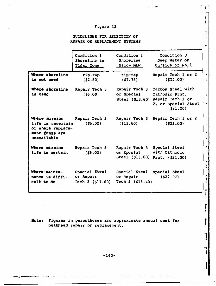
I1Figure 33
GUIDELINES FOR SELECTION OF 1REPAIR OR REPLACEMENT SYSTEMS
Condition 1 Condition 2 Condition 3Shoreline in Shoreline Deep Water onTidal Zone Below MLW Outside of Wall
Where shoreline rip-rap rip-rap Repair Tech 1 or 2is not used ($2.50) ($7.75) ($21.00)Where shoreline Repair Tech 3 Repair Tech 3 Carbon Steel with
is used ($6.00) or Special Cathodic Prot. ,Steel ($13.80) Repair Tech 1 or
2, or Special Steel t($21.00)
Where mission Repair Tech 3 Repair Tech 3 Repair Tech 1 or 2life is uncertain, ($6.00) ($13.80) ($21.00)or where replace-ment funds are!unavailable
Where mission Repair Tech 3 Repair Tech 3 Special Steellife is certain ($6.00) or Special with Cathodic
Steel ($13.80) Prot. ($21.00)
Where sainte- Special Steel Special Steel Special Steel Inance is diffi- or Repair or Repair ($22.90)cult to do Tech 2 ($11.60) Tech 2 ($15.40)
Note: Figures in parentheses are approximate annual cost forbulkhead repair or replacement.I
-140-
l1

IX. ANALYSIS OF REPAIR WORKAT THE NAVAL AIR STATION; NEW YORK
The bulkhead at the southeast c,:ner of the Naval AirStation, New York, is a typical illustration of a facilityapproaching the end of its functional life. This bulkheadhas been in place since 1942 and has had no appreciablemaintenance since that time. In one section, the piling webat the top of the wall is completely eroded. In other sec-tions, there are large holes just above and below the meanlow water line, allowing erosion of backfill material. Aheavy coating of scale covers the entire length and depthof the bulkhead on the exposed side. There are also someareas in which the bolts joining the tie-rods to the bulk-head have pulled le-se. Although the bulkhead is in noimmediate danger of actual structural failure, it should berepaired or replaced in the near future to prevent add.tionalloss of backfill and to arrest further structural deteriora-tion.
A. Environmental Factors
Before an analysis of the cost of various repair andreplacement techniques could be made, the bulkhead's environ-ment had to be examined. A study of the climatic, tidal,biological, and electrical features of the area indicatedthat there were no unusual design conditions to be considered.There are no prevailing winds which might accentuate normalsurf and wave conditions in the adjacent waters. The Rocka-way Beach Peninsula stands between the bulkhead and the opensea and blunts the effect of storm winds from the southeast.The tidal flow runs roughly parallel to the bulkhead. Bxoeptfor the area between the ramp and the wharf, the water is notdeep and there is little evidence of scouring along the mudline.
Because of the porosity of the soil and the flatness ofthe terrain, excavations in this area revealed little groundwater down to the mean high water level. There appears tobe substantial rain runoff, however, from the seaplane apronand runway adjacent to the seaplane ramp. This runoff seems
-141-
h* -6

..1
to flow down behind the wall in the section between stations ]13 + 40 and 21 + 17. This runoff probably accelerates cor-rosion on the inside of the wall and contributes to thewashing of backfill through holes in the bulkhead in this area.
Pollution is not a major problem. Because of the rela-tive cleanliness of the water, the shallowness of the bay,and the subsequently higher water temperature, conditionscould be satisfactory for infestation of marine borers.These conditions may be a deterrent to the use of timber inthis area.
There is no evidence of the existence of high electricalpotential in the soil adjacent to the wall.
Reavy scale and the complete erosion of the webbing atthe top of the wall are factors in the selection of a repairor maintenance method. A substantial amount of work will benecessary to prepare the surfaces of the wall for any bondedcoating or repair material such as concrete.
The physical environment of the bulkhead appears normal,but the economic environment is difficult to ascertain. Thebase is used as a reserve pilot training station. Expansionto a broader mission status may be hampered by the proximityof deep water, roads and bridges, and the Kennedy InternationalAirport. The mission life of the bulkhead is dependent onthe mission life of the base. The bulkhead is one of the lessvital elements in the operation of the base and, with theexception of the section of the bulkhead built into the tankerwharf and the adjacent section which supports a roadway andparking apron, the cost-of-failure is not an importantconsideration. The bulkhead in the vicinity of the tankerwharf, however, should be maintained in excellent condition.Any failure in this area could jeopardize the fuel supplylines for the base. The economic factors in the rc.. ir orreplacement of this section, therefcre, may be outweighed bythe necessity of keeping the wharf in operating condition.
In summary, the envirorarnental factors do not appear toinfluence the choice of repair or replacement proceduresexcept for the uncertainty concerning the mission life of thebulkhead and the need to maintain the struccure in the vicinity
-142-
.9
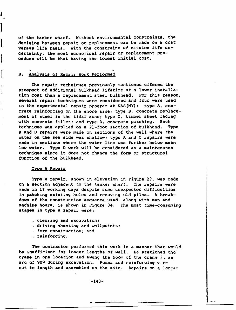
of the tanker wharf. Without environmental constraints, thedecision between repair or replacement can be made on a costversus life basis. With the constraint of mission life un-certainty, the most economical repair or replacement pro-cedure will be that having the lowest initial cost.
B. Analysis of Repair Work Performed
The repair techniques previously mentioned offered theprospect of additional bulkhead lifetime at a lower installa-tion cost than a replacement steel bulkhead. For this reason,several repair techniques were considered and four were usedin the experimental repair program at NAS(NY) : type A, con-crete reinforcing on the shore side; type B, concrete replace-mont of steel in the tidal zone; type C, timber sheet facingwith concrete filler; and type D, concrete patching. Eachtechnique was applied on a 21-foot section of bulkhead. TypeB and D repairs were made on sections of the wall where thewater on the sea side was shallow; tiqe A and C repairs weremade in sections where the water line was further below meanlow water. Type D work will be considered as a maintenancetechnique since it does not change the form or structuralfunction of the b'.lkhead.
Type A Repair
Type A repair, shown in elevation in Figure 27, was madeon a section adjacent to the tanker wharf. The repairs weremade in 17 working days despite some unexpected difficultiesin patching existing holes and removing old piles. A break-down of the construction sequence used, along with man andmachine hours, is shown in Figure 34. The most time-consumingstages in type A repair were:
"• clearing and excavation;"* driving sheeting and wellpoints;"• form construction; and". reinforcing.
The contractor performed this work in a manner that wouldbe inefficient for longer lengths of wall. He stationed thecrane in one location and swung the boom of the crane i . anarc of 900 during excavation. Forms and reinforcing - recut to length and assembled on the site. Repairs on a onc•-
-143-
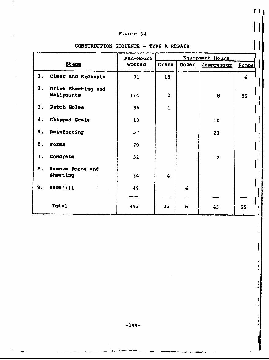
Figure 34
CONSTRUCTION SEQUENCE - TYPE A REPAIR I fMan-Hours Equi ment Hours
stag Worked Crane Dozer Compressor Pum s
1. Clear and Excavate 71 15 6
2. Drive Sheeting andWall-points 134 2 8 89
3. Patch Holes 36 1
4. Chipped Scale 10 10 15. Reinforcing 57 23
6. Forms 70
7. Concrete 32 2 18. Remove Forms and I
Sheeting 34 4
9. Backfill 49 6 1Total 493 22 6 43 95
-144-
- - - - a
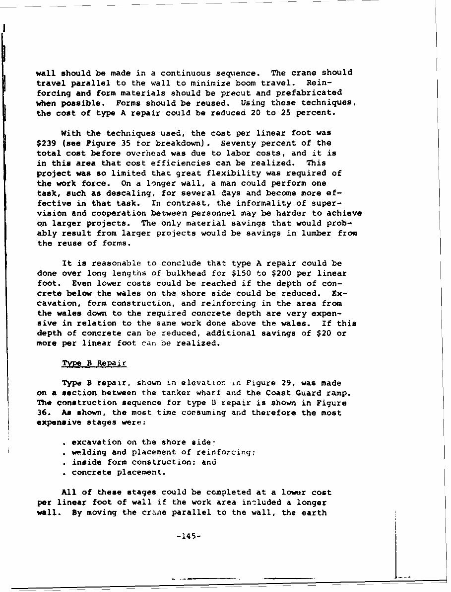
wall should be made in a continuous sequence. The crane shouldtravel parallel to the wall to minimize boom travel. Rein-forcing and form materials should be precut and prefabricatedwhen possible. Forms should be reused. Using these techniques,the cost of type A repair could be reduced 20 to 25 percent.
With the techniques used, the cost per linear foot was$239 (see Figure 35 for breakdown). Seventy percent of thetotal cost before overhead was due to labor costs, and it isin this area that cost efficiencies can be realized. Thisproject was so limited that great flexibility was required ofthe work force. On a longer wall, a man could perform onetask, such as descaling, for several days and become more ef-fective in that task. In contrast, the informality of super-vision and cooperation between personnel may be harder to achieveon larger projects. The only material savings that would prob-ably result from larger projects would be savings in lumber fromthe reuse of forms.
It is reasonable to conclude that type A repair could bedone over long lengths of bulkhead for $150 to $200 per linearfoot. Even lower costs could be reached if the depth of con-crete below the wales on the shore side could be reduced. Ex-cavation, form construction, and reinforcing in the area fromthe wales down to the required concrete depth are very expen-sive in relation to the same work done above the wales. If thisdepth of concrete can be reduced, additional savings of $20 ormore per linear foot can be realized.
Type B Repair
Type B repair, shown in elevation in Figure 29, was madeon a section between the tanker wharf and the Coast Guard ramp.Tha construction sequence for type 3 repair is shown in Figure36. As shown, the most time consuming and therefore the mostexpensive stages were:
. excavation on the shore side-. welding and placement of reinforcing:. inside form construction; and. concrete placement.
All of these stages could be completed at a lower costper linear foot of wall if the work area included a longerwall. By moving the cr.ane parallel to the wall, the earth
-145-
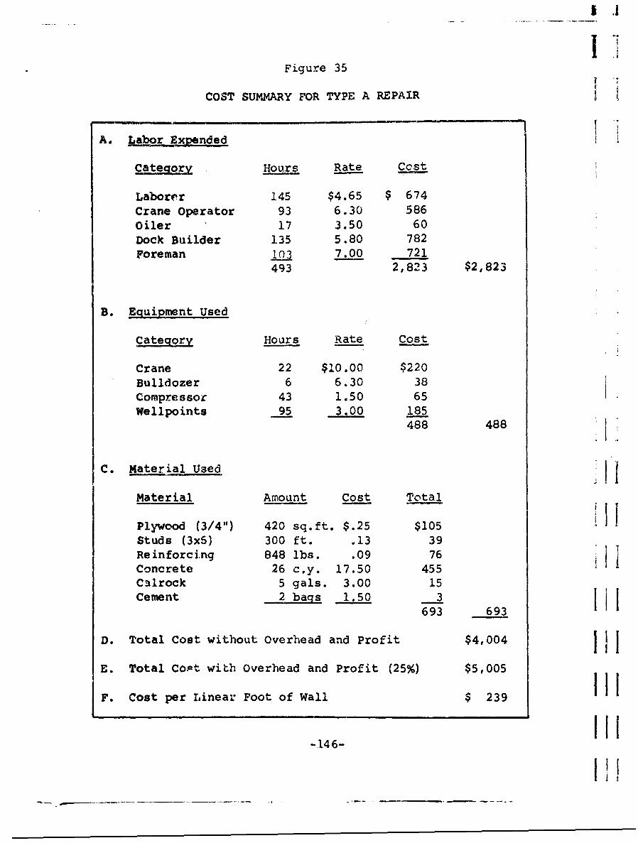
I !
I iFigure 35
COST SUMMARY FOR TYPE A REPAIR
A. Labor Expended
Categorv Hours Rate Cost
Laborer 145 $4.65 $ 674Crane Operator 93 6.30 586Oiler 17 3.50 60Dock Builder 135 5.80 782Foreman 103 7.00 721
493 2,823 $2,823
B. Equipment Used
Category Hours Rate Cost
Crane 22 $10.00 $220Bulldozer 6 6.30 38Compressor 43 1.50 65Wellpoints 95 3.00 185
488 488
0 iIIC. Material Used i
Material Amount Cost Total
Plywood (3/4"1) 420 sq.ft. $.25 $105 iStuds (3x6) 300 ft. .13 39Reinforcing 848 lbs. .09 76Concrete 26 c.y. 17.50 455Calrock 5 gals. 3.00 15Cement 2 bags 1.50 3 1 1 I
693 693
D. Total Cost without Overhead and Profit $4,004 i
E. Total Copt with Overhead and Profit (25%) $5,005
F. Cost per Linea Foot of Wall $ 239I
-146-
Ii!
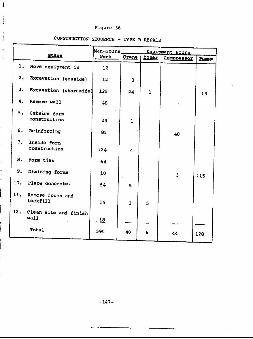
Figure 36
CONSTRUCTION SEQUENCE - TYPE B REPAIRMan -Hours Eento
stiage Work Clans Dozer Comipresgor Pumion
1. Move equipment in 12
2. Excavation (seaside) 12 3
3. Excavation (shoreside) 125 24 1 13
4. Remove wall 48 1
5. Outside formconstruction 23 1
6. Reinforcing 85 40
7. Inside formconstruction 124 4
8. Form ties 64
9. Dtaining forms' 10 3 115
10. Place concrete.A 54 5
11. Remove forms andbackfill 15 3 5
12. Clean site and finishwall 18
Total 590 40 6 44 128
-147-
.5
excavated would be moved a shorter distance and the cranewould not have to be repositioned as often as it was. Thereinforcing could be placed in longer sections. Prefabricatedforms could be stripped off completed sections and moved tothe next length of wall to be repaired. Several sections ofconcrete could be poured at one time. Using these or 'imilartechniques, it is estimated that the actual cost of type Brepair, i.e., $268 per linear foot (see Figure 37) could bereduced by 15 to 20 percent.
The contractor performed the type B repair before otherrepair techniques were attempted. He tried to drain thearea inside the wall but below the tidal zone with two pumps.This draining technique proved unsatisfactory and resultedin delay during the excavation, form construction, and concreteplacement stages. As a result of this experience, he usedi well point system on the type A repair. Some cost reduc-tions would have resulted from using a well point systemduring type B repairs.
Material savings resulting from type B repair over longlengths of bulkhead would be limited to timber usage. Byreusing forms, a small cost saving may be achieved. As dis-cussed under type A repair, design changes which would resultin less concrete below the wales would lower the cost of this ..
repair technique.
This type of repair calls for concrete on the ocean sidedown to a depth of 2 feet below mean low water. At the loca-tion where this work was performed, the mud line was above meanlow water, whichimeant that excavation in front of the wallwas necessary to facilitate the plaoement of forms. Wherethe mud line is more than 2 feet below mean low water, acounterweight outrigger beam may have to be installed tosupport the weight of the concrete wall while the concrete isin a plastic state. It is assumed that the construction costwould not vary greatly between excavation and placement of asupport beam. If the mud line elevation is such that theexterior form can be placed on the shore, however, some con-struction cost savings may result.
In summary, type B repairs may be made for $175 to $250per linear foot over long lengths of wall. Some possibilityof lower costs exists if the amount of concrete placed belowthe wale can be reduced.
-148-
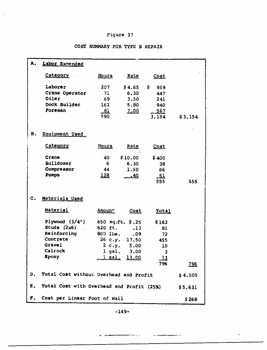
Figure 37
COST SUMMARY FOR TYPE B REPAIR
A. Labor Expended
Category Hours Rate Cost
Laborer 207 $4.65 $ 959Crane Operator 71 6.30 447Oiler 69 3.50 241Dock Builder 162 5.80 940Foreman 81 7.00 567
590 3,154 $3,154
B. Equipment Used
Category Hours Rate Cost
Crane 40 $10.00 $400Bulldozer 6 6.30 38Compressor 44 1.50 66Pumps 128 .40 51
555 555
C. Materials Used
Material Amount Cost Total
Plywood (3/4") 650 sq.ft. $ .25 $162Studs (2 x6) 620 ft. .13 81Reinforcing 800 lbs. .09 72Concrete 26 c.y. 17.50 455Gravel 2 c.y. 5.00 10Calrock 1 gal. 3.00 3Epoxy _1 gal. 13.00o0
796 796
D. Total Cost without Overhead and Profit $4,505
E. Total Cost with Overhead and Profit (25%) $5,631
F. Cost per Linear Foot of Wall $268
-149-
£
Type C Repair
Type C repair work at the New York Naval Air Stationwas performed between the tanker wharf and the seaplane rampin an area where the water depth in front of the wall was15 to 20 feet. The work was performed in five working daysand consisted of three stages:
"* assembly of the timber facing on shore;
". placement of the facing against the steelbulkhead; and
"• filling the open cell areas between the timberand steel with concrete.
The repair work was performed in a most efficient mannerbut did not produce the type of repair that was specified.According to specifications, the timbers were to be indi.vidu-ally driven and sprung into the wall. Then the timbers wereto be joined into a composite facing and bolted to the wall(see Figure 38). The timbers could not be driven to thespecified elevation because the mud line was below this ele-vation. As a result, the timbers were assembled on shore anddropped into place as a unit. In contrast to type A and Brepairs, type C repair would cost more over a longer lengthof wall if the installation was done properly. The actualcost of $68 per linear foot (see Figure 39) could increase to$100 to $150 per linear foot if each pile were drivenseparately.
ype .D Maintenance
Type D maintenance was performed on the bulkhead adjacentto the seaplane ramp. Twenty-one holes were selected formaintenance and some fill behind each hole was remocd toprovidp room for a concrete patch. The metal surrounding thehole was cleaned to provide a good bcnding surface for con-crete and epoxy. Then, the holes were fillea with concrete upto the steel piling surface and an exterior layer of epoxy wasapplied (see Pigure 40).
The cost of type D maintenance is a function of the size
and location of the holes. The holes on which maintenance was
-150-
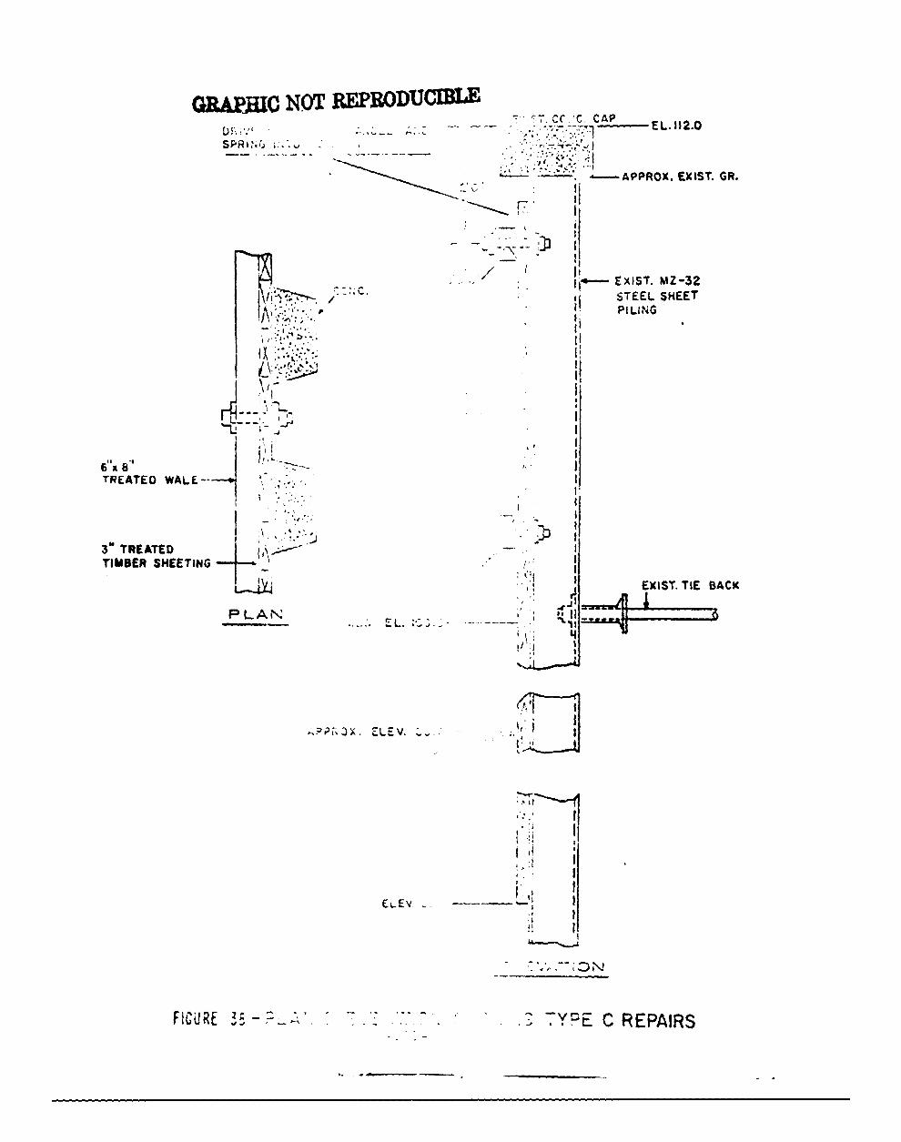
GRAPUIC NOT REPRODUCIBLE- , C. CAP
"S R w" . ,. - --.- -, - - U-.,
':- APPROX. EXIST. GR.
* / t i
c. . .. " .,- EXIST. MZ-32
STEEL SHEETPILING
6"a 8'i!.,, iIL•L•Gs.•
TREATED WALE--
3" TREATED I/ -
TIMBER SHEETINGEilI
F P1LARE REPAIRST.TEBC
-•:.;-;...--..-""+"'" :""''I
TREATED WAL E +---E -
P L A;' 35 •Z .. .. : -. - ... .. -- Y:,R PA R
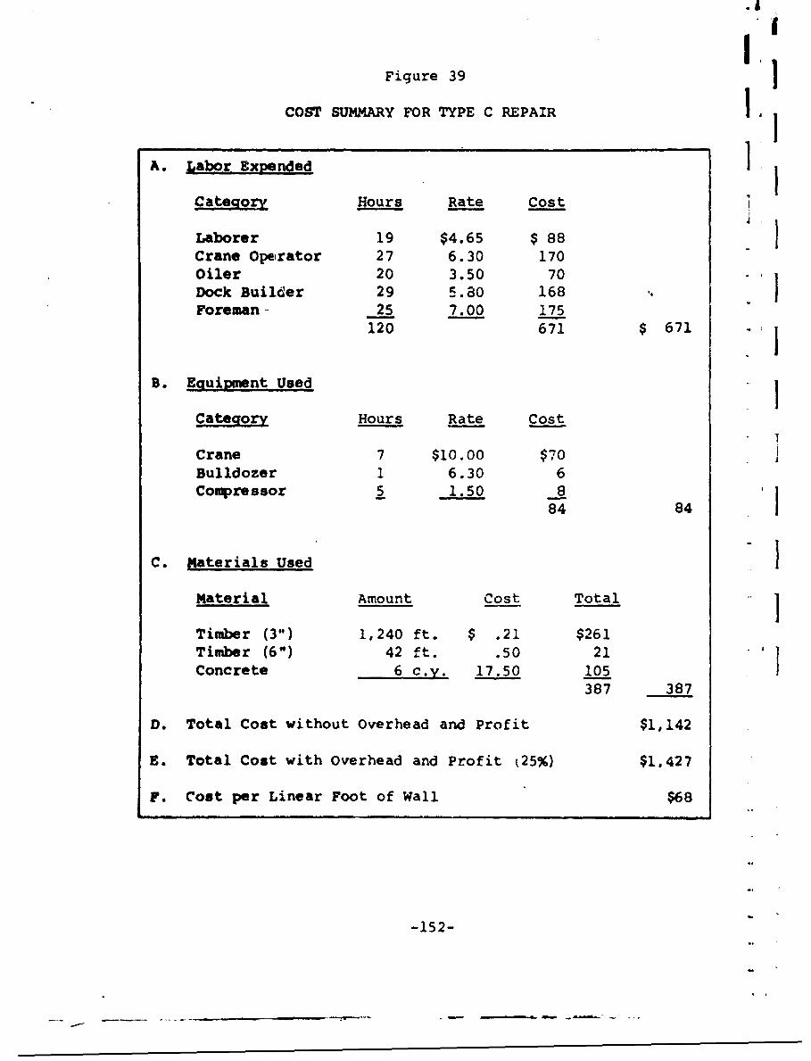
IIFigure 39
COST SUMMARY FOR TYPE C REPAIR ,
A. Labor Expended ICategory Hours Rate Cost
Laborer 19 $4.65 $ 88Crane Operator 27 6.30 170Oiler 20 3.50 70Dock Builder 29 5.80 168Foreman- 25 7.00 175
120 671 $ 671
B. E;auipment Used
Category Hours Rate Cost
Crane 7 $10.00 $70 I
Bulldozer 1 6.30 6Compressor 5 1.50 8
84 84
C. Materials Used IMaterial Amount Cost Total ITimber (3") 1,240 ft. $ .21 $261Timber (6") 42 ft. .50 21 1Concrete 6 c.y. 17.50 105 1
387 387
D. Total Cost without Overhead and Profit $1,142
E. Total Cost with Overhead and Profit k25%) $1,427
F. Cost per Linear Foot of Wall $68
-152-
--- ---- _ _ _ _
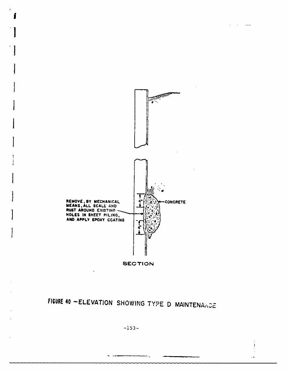
I
'1
I'
1
1 0'
II
I
I REMOVE, BY MECHANICAL 4"' CONCRETEMEANSALL SCALE AND JRUST AROUNO EXISTINGHOLES IN SHEET PILING,AND APPLY EPOXY COATING
41
SECTION
FICURE 40 -ELEVATION SHOWING TYPE D MAINTENAJ'%.E.
-153-
performed at the New York Naval Air Station were in the websection of the piling at the elevation of the wales (approxi-mately mean water level). Work had to be done at low tidein water depths of 0 to 3 feet. The cost of this maintenancework was $14 per hole (see Figure 41). Since the holes ap-peared in adjoining web sections, the work was done on 21piles over a 40-foot length at a cost of $7.50 per linear footof bulkhead.
It is difficult to project how the cost of concretepatching will vary without observing more work. The cost willvary with the number, size, and location of the holes ratherthan the length of wall to be repaired. It does not seemthat major cost savings can be assumed for work on a longerwall. Concrete patching is not skilled work and repetitionmay not result in greatly increased work efficiency.
C. Summary and Recommendations
The experimental repair projects at the New York NavalAir Station offered the opportunity to test repair proceduresin a typical bulkhead environment. The test projects alsoprovided an opportunity to gather cost data on repair proce-dures. Unlike the cost of replacement and maintenance tech-niques, the cost of many of the suggested repair techniqueshas not been adequately documented.
The tests did show that functiohal repair work can bedone on steel bulkheads. The condition of the remainingsteel was more than adequate to support the placement ofnew bulkhead materials. In addition, the cost data indicatesthat repairs can be made within the cost range estimated bythe Eastern Division of the Naval Facilitiis Engineering Com-mand. Although the actual costs were higher than es'limated,there are several procedural improvements which ca- Le insti-tuted in projects involving longer lengths of bulkhead thatwill reduce the cost per linear foot. Finally, the testsindicated that the repaired bulkhead was structurally ade-quate to fulfill its function for several years after theend of life of the original bulkhead.
Type A repairs actually cost $239 per linear foot; theestimate for this t-,pe of repair was ,.,proximately $150 per
-154-
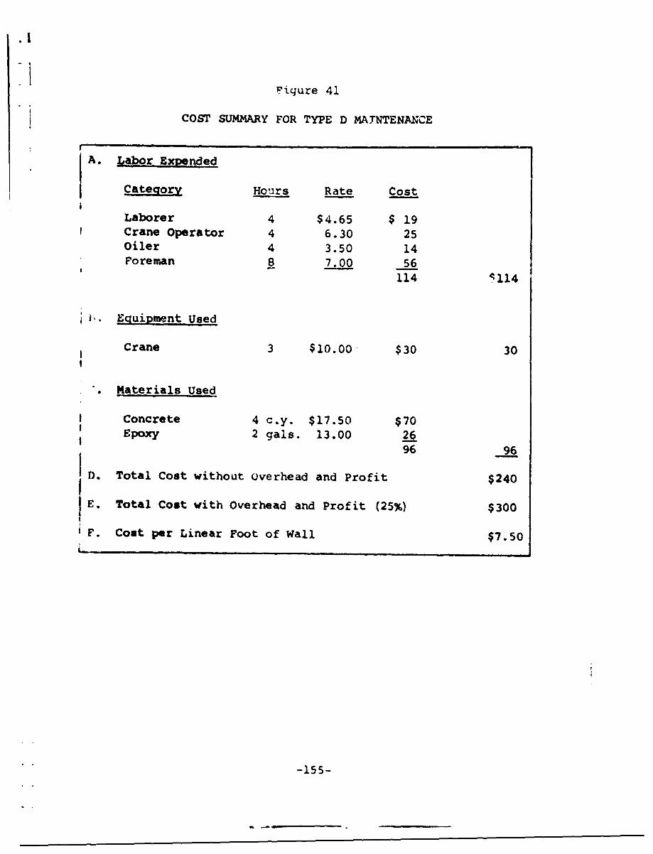
,.!
Pigure 41
COST SUMMARY FOR TYPE D MATNTENANCE
A. qabor Expended
Category Hours Rate Cost
Laborer 4 $4.65 $ 19Crane Operator 4 6.30 25Oiler 4 3.50 14Foreman 8 7.00 56
114 •114
kJ. Eguipment Used
Crane 3 $10.00 $30 30
. Materials Used
Concrete 4 c.y. $17.50 $70Epoxy 2 gals. 13.00 2696 96
D. Total Cost without Overhead and Profit $240
E. Total Cost with Overhead and Profit (25%) $300
F. Cost per Linear Foot of Wall $7.50
-155-
linear foot. With procedural improvements and more efficientuse of materials, howeve,:, it qs now possible to estimate a
cost of $150 to $200 per linear foot for this type of repair.Type A repairs can be justified by, a life extension of 10 to15 years when the alternative is replacement with carbon steel.These repairs are best suited for use in areas where repairsare difficult to make and where access to -4,e front face ofthe existing bulkhead is difficult. This technique may bebest for repairs under and adjacent to the wharf and seaplaneramp.
Type B repairs cost $268 per lineas foot ac the NavalAir Station, New York. The estimate of 150 to ,.175 periinear foot proved to be low exarn with antic-eated improve-ments in construction procedures. Repairs of this type canbe justified by a life extension of 15 to 20 years if com-pared with a carbon ýtcel ieplacemr-t bulkhead. Type Brepair- may be suited to renovatio: of a bulkhead if theappearance of the structure is important and if the wall maybe used for berthing ships. There are no sections of thebulkhead at the Naval Air Station ii New York for which thistechnique is ideally suited.
Since type C repairs were not made in accordance withthe d.sign specifications, it is difficult to project theactual cost of this type of repair. The cost should notexceed $150 per linear foot, however, and could be justifiedly a 10 to 15 year life extension. The cost and efficacy ofthis type of repair depends on the depth to which the tiwlberfacing must be driven. When the mud line is less than 15feet from the top of the bulkhead and when the depth of wateris less than 2 feet at low tide, this type of repair can bedone inexpersive'.y znu can be expected to provide a long lifeextension tor the bufiiwead. Type C repairs (or repair tech-nique 3, aiscuzsed in Section VIII) are best suited foruse on sh.llow water bulkheads, such as the secti.oz. -tweenthe Rockaway Bridge and the seaplane rarip, or the bectionbetween the tanker wharf and the Coast Guard area at theNew York Naval Air Station.
Type D repairs idescribed in Section VIII as concretepatching) cost only $10 to $20 per hole. While it is effec-
tive in suppressing erosion in the area of the patch, it may
-156-
not extend the functional life of the bulkhead by anymeasurable period. In addition, if patching is required ona yearly basis, it may prove to be a very expensive maintenancetechnique. This type of maintenance is best suited to con-ditions in which mission life is uncertain and the cost-of-failure of the bulkhead is low.
-157-
X. PROMISING RESEARCH AXD DEVELOPMENT AREAS
In the previous discussions of installation, mainte-nance, and repair possibilities for shore protection struc-tures, the state of the art has been a limiting factor inseveral cases. The following brief paragraphs describedome of these present :t~hnological limitations and identifyazeds whexe research aiid development could lead to majorimprovements in bulkhead construction and maintenance. Em-phasis has been placed on areas in which an improvement;J.uld 'lad 'o major ceassessment of present-day practicestAther than on evolutionary development of current materials•Ad methods.
.. Coatins
Present coatings for underwater protiction of bulkheadsmust be applied before t..he structure is placed in its serv-ice environment. Thcbs coatings cGntinuc to be effectiveagainst corrosion from the sea water for a period of severalmonths to several years. At that time, since there is noeconomical technique for recoating the underwater surfaces,dlternative means for zatintenance and repair of the bulk-head must be employed. An effective technique for under-water application of substantial coatings is needed.
Two approaches to the development of an underwatercoating system s-eem to merit further research. The firstapproach is to deielop a new coating that can be easilyapplied underwater, perhapL; using straightforward applica-tien techniques such as brushing or spraying. The cemen-tiferous paints discussed in Section IV are a step in thisdirection. A second approach is that of finding novel ap-plications for presently available coatings. Local dewater-ing, maintained by a sealed container in which applicationand c,.ring can proceed, is an example of such an applica-ticn.
Sincg epoxy resin coatings have been found to be effec-tive for protection after underwater application, this
-158-
9 4
ysfi-m could be pursued to make it economically feasible.p'ssibility in a mixing nozzle for combination of the two-
"na'k epoxy Pystem just prior to application,coupled with abrush applicator or other spreader. Such a technique wouldpermit more rapid, semi-continuous application of the epoxy'oating to the bulkhead surface.
The above coatings are concerned with formation of a'ilm to separate the bulkhead from the sea water. Otherilternative mechanisms for coating protection are possible.
•.or example, the corrosive oxygen concentration cell just.elnw water level causes deterioration of sheet steel bulk-s.eads. The traditional approaches to inhibiting this cor-.osion have been cathodic protection and/or a protective'nating film. Another approach would be to balance the
rxgen distribution throughout the depth of the underwater'- tion of the structure- by removing the excess oxygen from
"'1' surface layer of witer near the bulkhead. This approach4ght be accomplished, for instance, by a coating that ad-
=orbcd the dissolved oý_ygen in the water and bubbled it back_nto the atmosphere. This coating could be applied at theinitial installation of the bulkhead and, since it wouldprotect by a different mechanism, could outlast normal filmcoatings in effective lifetime.
B. Facing Systems
In many cases, a deteriorated bulkhead structure still>ias sufficient structural integrity to support its backfillloading, and maintenance and repair techniques are aimed'simply at preventing further deterioration. Since coatingtinderwater continues to be a problem, development of a.ionstructural facing system to protect the bulkhead fromfurther deterioration by physically separating it from thesea water may be a desirable alternative. The faci-i systemwould have to be lightweight so that little additional over-turnirg moment would be added to the original bulkheadstructure. The system might consist of an outer form andan inert filler material to seal the space between thatform and the original bulkhead, as described in the discus-sion on repair %echniques. Research might be devoted to
-159-J
the development of economical materials and constructiontachniques for this type of facing repair system.
C. Composite Materials
Composite material systems generally are made up of twoor more component materlals, the combination of which improvesupon the characteristics of the individual component materials.Two kinds of composite construction can be visualized for ap-plication to bulkhead construction.
one type of composite construction v-ould simply applythe traditional materials from which shore protection facil-ities are constructed in such a way that the best availablematerial was used in each particular zone of attack fromthe environment. This approach is summarized in Figure 42,where the three trad-'t-ional materials for shore protectionare evaluated in each of the six zones of marine environ-mental attack. This approach is a simple extension of the11composite construction" approach used for years in buildingdocks, where wood piles are used in underwater areas andthe superstructure above the water line is built of concrete.It has obvious advantages in that it places the most resist-ant material in the proper position for each kind of attack.
A second type of composite materials approach wouldiequira the developait-nt of new construction materials perja composite on the microscopic scale only. Fiberglasreinforced plastics and plywood are examples of such com-posite materials. A materials combination to replace sheet-steel piling as a bulkhead material would need to havestiffness and strength characteristics near those of steel,and corrosion resistance characteristics near those of thenoble metals. Two possible forms for the development ofsuch composite materials are commonly used in other iields:fiber-reinforced matrices and laminated systems. An exampleof the first form for marine application might be continuous,oriented high-strength steel wires used to reinforce a matrixof a ductile, corrosion-resistant metal or ceramic. An Texample of a laminated system inight be a low density core,surrounded by relatively thin layers of sheet-steel and
-160-

then covered with a thin layer of inert, continuous poly-meric or ceramic coating for corrosion resistance. The num-ber of possible combinations is unlimited, and the fiber re-inforced or laminate system could even be combined with thezonal approach so that the outer coatings on the compositematerial would change to meet the demands of each environ-mental zone.
A su•rvey of the combinations of composite materialsthat are presently available, with follow-on research toeither adapt one of the materials available or to developa new composite material tailored for the particular bulkheadapplicable, would seem to be a fruitful area for researchand development.
1II
-161-
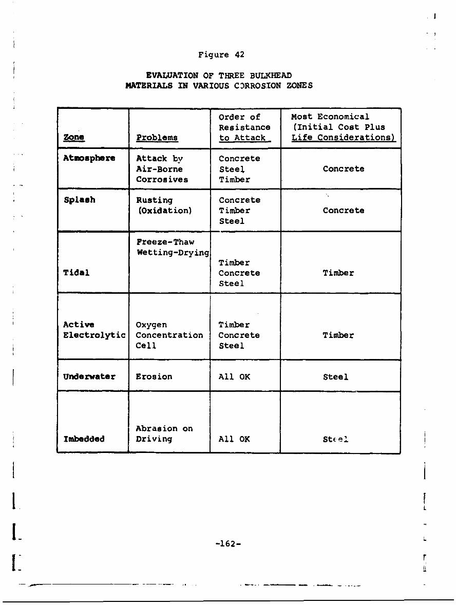
Figure 42
EVALUATION OF THREE BULKHEADMATERIALS IN VARIOUS CZ)RROSION ZONES
Order of Most EconomicalResistance (Initial Cost Plus
zone Problems to Attack Life Considerations)
Atmosphere Attack by ConcreteAir-Borne Steeli ConcreteCorrosives Timber
Splash Rusting Concrete(Oxidation) Timber Concrete
Steel
Freeze-ThawWetting-Drying
TimberTidal Concrete Timber
Steel
Active Oxygen TimberElectrolytic Concentration Concrete Timber
Cell Steel
Underwater Erosion All OK Steel
Abrasion onImbedded Driving All OK St.el
-162-1" r
XI. CONCLUSIONS
Selection of the most cost effective means for replace-ment, maintenance, or repair of sheet-steel bulkheads involvesconsideration of the following major factors:
"* materials that will provide structuralintegrity in the bulkhead environment;
"* installation cost;
"• functional life or life extension;
". annual or periodic costs of maintenance; and
"* mission life of the bulkhead.
"When the mission life exceeds the functional life, an annualcost comparison of aliernatives can be made, using the formu-las in Section VII. An analysis should also be made of theenvironmental factors, including the economic, climatic, andother conditions that may favor or militate against the use ofa material system. If the bulkhead is in good functionalcondition, the alternative courses of action are:
"* annual maintenance;
"* periodic maintenance; and
"* no maintenance.
These alternatives should be compared on an annual cost basis,taking into consideration the life extension of the bulkheadoffered. by tuq use of the first two alternatives.
With the bulkhead approaching a failure condition, thereare three general alternatives available:
• maintain as often as required to extendfunctional life a few more years;
-163-
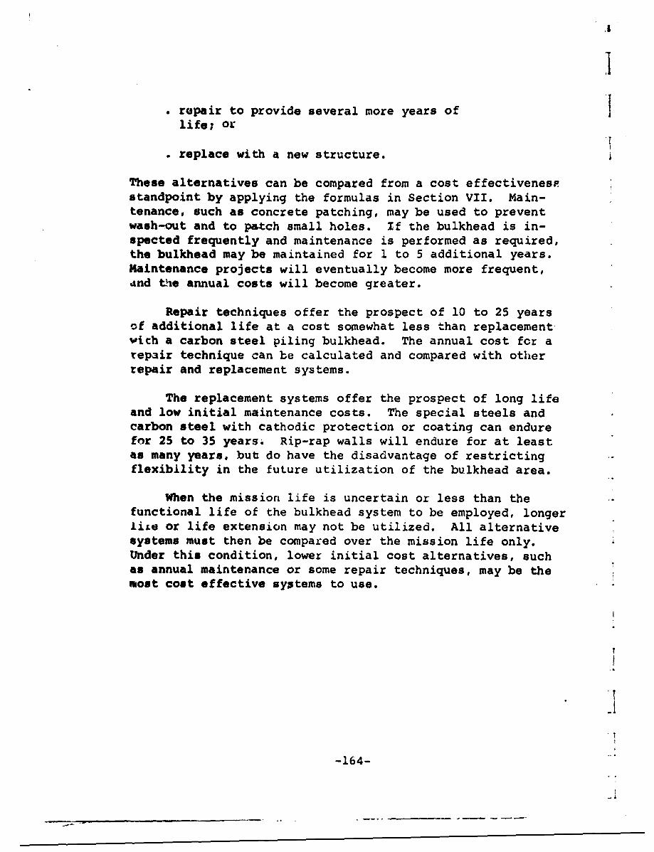
* repair to provide several more years oflife; or
. replace with a new structure.
These alternatives can be compared from a cost effectivenespstandpoint by applying the formulas in Section VII. Main-tenance, such as concrete patching, may be used to preventwash-out and to patch small holes. If the bulkhead is in-spected frequently and maintenance is performed as required,the bulkhead may be maintained for 1 to 5 additional years.Maintenance projects will eventually become more frequent,And the annual costs will become greater.
Repair techniques offer the prospect of 10 to 25 yearsof additional life at a cost somewhat less than replacementwith a carbon steel piling bulkhead. The annual cost for arepair technique can be calculated and compared with otherrepair and replacement systems.
The replacement systems offer the prospect of long lifeand low initial maintenance costs. The special steels andcarbon steel with cathodic protection or coating can endurefor 25 to 35 yearsý Rip-rap walls will endure for at leastas many years, but do have the disadvantage of restrictingflexibility in the future utilization of the bulkhead area.
When the mission life is uncertain or less than thefunctional life of the bulkhead system to be employed, longerLiLe or life extension may not be utilized. All alternativesystems must then be compared over the mission life only.Under this condition, lower initial cost alternatives, suchas annual maintenance or some repair techniques, may be themost cost effective systems to use.
-16.4
-164-..
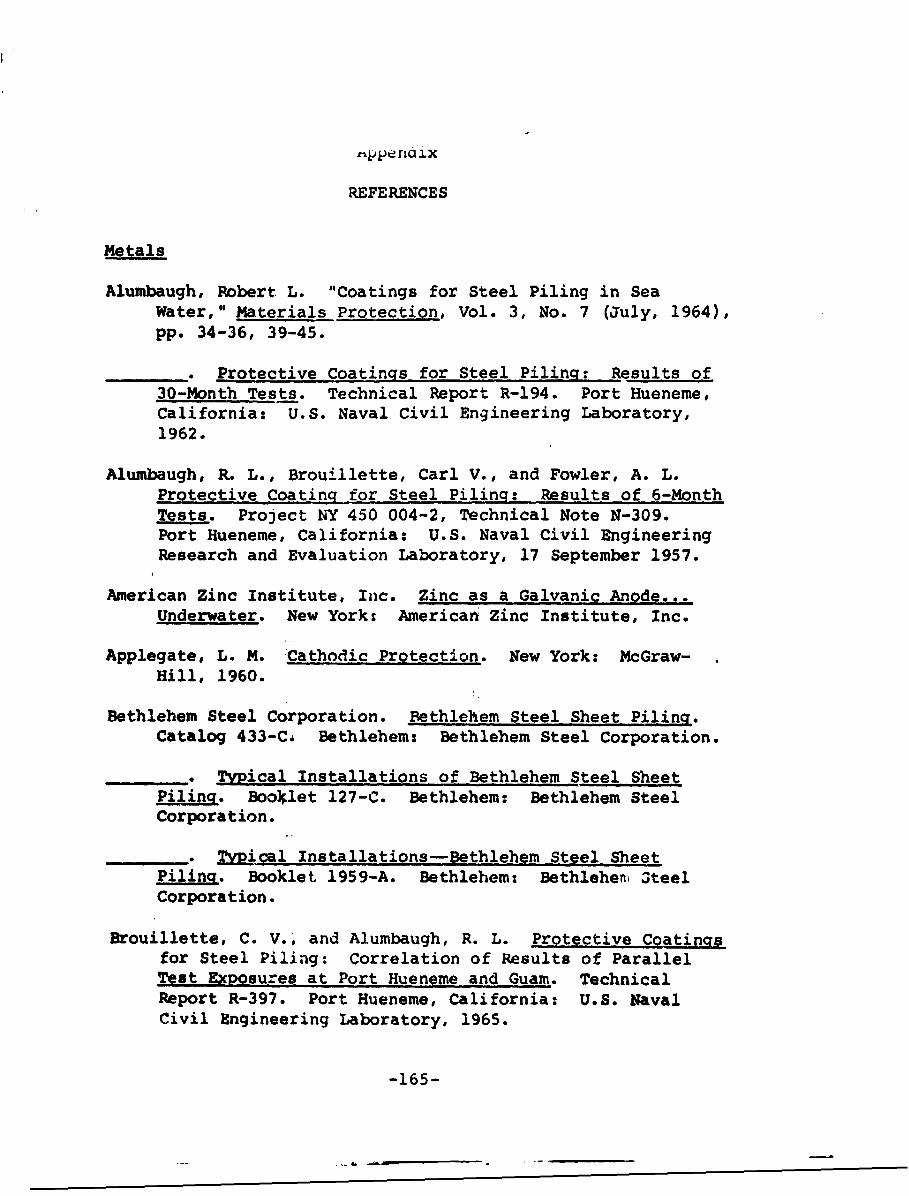
r•pp riG ix
REFERENCES
Metals
Alumbaugh, Robert L. "Coatings for Steel Piling in SeaWater," Materials Protection, Vol. 3, No. 7 (July, 1964),pp. 34-36, 39-45.
• Protective Coatings for Steel Piling: Results of30-Month Tests. Technical Report R-194. Port Hueneme,California: U.S. Naval Civil Engineering Laboratory,1962.
Alumbaugh, R. L., Brouillette, Carl V., and Fowler, A. L.Protective Coating for Steel Piling: Results of 6-MonthTests. Project NY 450 004-2, Technical Note N-309.Port Hueneme, California: U.S. Naval Civil EngineeringResearch and Evaluation Laboratory, 17 September 1957.
American Zinc Institute, Inc. Zinc as a Galvanic Anode...Underwater. New York; American Zinc Institute, Inc.
Applegate, L. M. 'Cathodic Protection. New York: McGraw-Hill, 1960.
Bethlehem Steel Corporation. Bethlehem Steel Sheet Piling.Catalog 433-C, Bethlehem: Bethlehem Steel Corporation.
_ TyPical Installations of Bethlehem Steel SheetPiling. Booklet 127-C. Bethlehem: Bethlehem SteelCorporation.
_ Typical Installations-Bethlehem Steel SheetPiling. Booklet 1959-A. Bethlehem: Bethleheni OteelCorporation.
Brouillette, C. V.; and Alumbaugh, R. L. Protective Coatingsfor Steel Piling: Correlation of Results of ParallelTest Exposures at Port Hueneme and Guam. TechnicalReport R-397. Port Hueneme, California: U.S. NavalCivil Engineering Laboratory, 1965.
-165-

Brouillette, C. V., and Hanna, A. E. Corrosion Survey ofSteel Sheet Piling. Technical Report 097. Port Hue-neme, California: U.S. Naval Civil Engineering Labo-ratory, 27 December 1960.
_ Second Corrosion Survey of Steel Sheet Piling.Technical Report R-467. Port Hueneme, California:U.S. Naval Civil Engineering Laboratory, August,1966.
Bureau of Ships and American Zi-c Institute. Zinc as a Gal-vani-c Anode. Bureau of Ships and American Zinc Insti-tute Symposium, 21-22 April 1955.
Burns, R. M., and Bradley, W. W. Protective Coatings forMetals. 2d ed. New York: Reinhold. 1955.
Butler, G., and Ison, H. C. K. Corrosion and Its Preventionin Waters. New York: Reinhold, 1966.
Corrosion Prevention and Control. Anti-Corrosion Manual.4th ed. London: Corrosion Prevention and Control,1962.
Drisko, Richard W., and Brouillette, C. V. "Comparing Coat-ings in Shallow and Deep Ocean Environments," MaterialsProtection, April, 1966.
Ebasco Services, Inc. Principles of Corrosion and CathodicProtection. New York: Ebasco Services, Inc.
Evans, U. R. An Introduction to Metallic Corrosion. NewYork: St. Martin's Press, 1963.
Forgeson, B. W., Southwell, C. R., and Alexander, A. L.Corrosion o2f Metals in Tropical Environments: Part 3-Underwater Corrosion of Ten Structural Steels.Report 5153. Naval Research Laboratory, 8 August 1958.
Glikman, L. A. Corrosion-Mechanical Strength of Metals.London: Butterworths, 1962.
Humble, H. A. "The Cathodic Protection of Steel Piling inSea Water," Corrosiol, Vol. 5 (1949), p. 292.
-166-
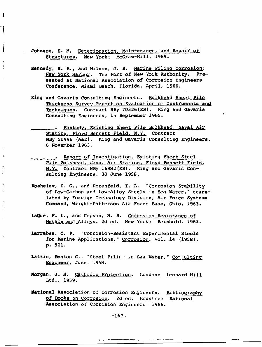
Johnson, S. M. Deterioration, Maintenance, and Repair ofStructures. New York: McGraw-Hill, 1965.
Xennedy, E. R., and Wilson, J. S. Marine Piling Corrosion:New York Harbor. The Port of New Yoik Authority. Pre-sented at National Association of Corrosion EngineersConference, Miami Beach, Florida, April, 1966.
King and Gavaris Coniulting Engineers. Bulkhead Sheet PileThickness Survey Report on Evaluation of Instruments aridTechniques. Contract NBy 70326(ES). King and GavarisConsulting Engineers, 15 September 1965.
,. Restudy, Existing Sheet Pile Bulkhead, Naval AirStation, Floyd Bennett Field, N.Y. ContractNBy 50996 (A&E). King and Gavaris Consulting Engineers,6 November 1963.
_ Report of Investigation, Existirg Sheet SteelPile Bulkhead, ihaval Air Station, Floyd Bennett Field,N.Y. Contract NBy 16982(ES). King and Gavaris Con-sulting Engineers, 30 June 1958.
Koshelev, G. G., and Rozenfeld, I. L. "Corrosion Stabilityof Low-Carbon and Low-Alloy Steels in Sea Water," trans-
lated by Foreign Technology Division, Air Force SystemsCommand, Wright-Patterson Air Force Base, Ohio, 1963.
LaQue, F. L., and Copson, H. R. Corrosion Resistance ofMetals and Alloys. 2d ed. New York: Reinhold, 1963.
Larrabee, C. P. "Corrosion-Resistant Experimental Steelsfor Marine Applications," Corrosion, Vol. 14 (1958),p. 501.
Lattin, Benton C., "Steel Piliiý, :n Sea Water, H Co-, ;i:tingElgineer, June, 1958.
Morgan, J. H. Cathodic ProtectiQn. London: Leonard HillLtd., 1959.
Mational Association of Corrosion Engineers. Bibliographyof BoOks on Corrosion. 2d ed. Houston: NationalAssociation of Corrosion Engineerc, 1966.
-167-
.1 J
Peabody, A. W., "Corrosion at Sea," Ebasco News, July, 1965.
Pittsburgh Chemical Company. Pitt Chem Coating Guidg forPiling. Revised. Pittsburgh: Pittsburqh ChemicalCompany, January, 1965.
Pleuset, M. S., Bass, B. C., and Hickling, R. Cathodic Pro-tection in Cavitation Damage. Report No. 85-10. Engi-neering Division, California Institute of Technology,November, 1958.
Priest, H. Malcolm, and Gilligan, John A. Desi•... Manual forHigh Strength Steels. Publication Number ADUSS 02-1327.Pittsburgh: United States Steel Corporation, Researchand Technology, 1965.
Rogers, T. H. The Marine Corrosion Handbook. Toronto:McGraw-Hill, 1960.
Scully, J. C. The Fundamentals of Corrosion. New York:rergamon Press, 1966.
1hreir, L. L. Corrosion. Vol. 2 of Corrosion Control.Edited by L. L. Shreir. London: George Newnes Ltd.,1963.
Tomashov, N. D. Theory of Corrosion and Protection ofMetals. New York: Macmillan, 1966.
Uhlig, H. E. Corrosion and Corrosion Control. New York:Wiley, 1963.
United States Steel Corporation. Mariner Steel Sheet and11 Piiinq. Pittsburgh: United States Steel Corporation,May, 1964.
"---- New, Hii.ih Strength Steel. Sheet Pilirg. Pitts-burgh: United Stases Steel Corporation, August, 1963.
. .Pt pl_.ns or Sections of Piling Instal-latiors.Pittsburghi United Stateýs Steel Corporation.
-1 6Ui-
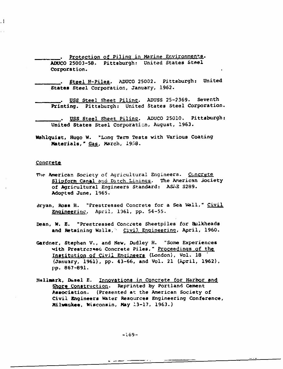
•Protection O Piling in Marine Environments.
ADUCO 25003-58. Pittsburgh: United States SteelCorporation.
_.__. _Steel H-Piles. ADUCO 25002. Pittsburgh; United
States Steel Corporation, January, 1962.
S_ * USS Steel Sheet Piling. ADUSS 25-2369. SeventhPrinting. Pittsburgh: United States Steel Corporation.
_' e USS Steel Sheet Piling. ADUCO 25010. Pittsburgh:United States Steel Corporation, August, 1963.
Wahlquist, Hugo W. "Long Term Tests with Various CoatingMaterials, Gas, March, 1958.
ThMe American Society of Agricultural Engineers. ConcreteSlipform Canal and DitchLinings. The American Societyof Agricultural Engineers Standard: AS*E S289.Adopted June, 1965.
dryan, Ross H. "Prestressed Concrete for a Sea Wall," CivilEnqineering., April, 1961, pp. 54-55.
Dean, W. E. "Prestressed Concrete Sheetpiles for Bulkheadsand Retaining Walls, Civil Engineering, April, 1960.
Gardner, Stephen V., and New, Dudley H. "Some Experienceswith Prestrczotei4 Concrete Piles," Proceecinqs of theIngtitution of Civil Engineers (London), Vol. 18 '(January, 1961), pp. 43-66, and Vol. 21 (April, 1962),pp. 867-891.
Hallmark, Drsel E. Innovations in Concrete for Harbor andShore Construction. Reprinted by Portland CementAsociation. (Presented at the Aaerican Society ofCivil Engineers Water Resources Engineering Conference,Milwaukee, Wisconsin, May 13-17, 1963.)
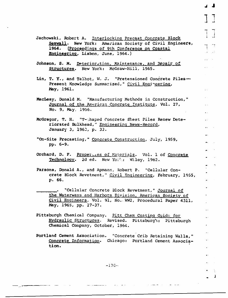
4 J
Jachowski, Robert A. Interlocking Precast Concrete BlockSeawall. New York: Ame:ican Society of Civil Engineers,1964. (Proceedings of 9th Conference on CoastalEngineering, Lisbon, June, 1964.)
Johnson, S. M. Deterioration, Maintenance, and Rkpair ofStructures. New York: McGraw-Hill, 1965.
Lin, T. Y., and Talbot, W. J. "Pretensioned Concrete Piles-Present Knowledge Summarized," Civil Enaggeerina,May, 1961.
MacLeay, Donald M. "Manufacturing Methods in Ccnstruction,"Journal of the American Concrete Institute, Vol. 27,No. 9, May, 1956.
McGregor, T. H. "T-Thaped Concrete Sheet Piles Renew Dete-riorated Bulkhead," Engineerinq News-Record,January 3, 1963, p. 33.
"On-Site Precasting," Concrete Construction, July, 1959,pp. 6-9.
Orchard, D. F. PropertLes of Materials. Vol. 1 of ConcreteTechnology. 2d ed. New Yo.-'.: Wiley, 1962.
Parsons, Donald A., and Apmann, Robert P. "Cellular Con-crete Block Revetment," Civil Engineering, February, 1955,p. 66.
"• "Cellular Concrete Block Revetment," Journal ofthe Waterways and Harbors Division, American Society ofCivil Engineers. Vol. 91, No. WW2, Procedural Paper 4311,May, 1965, pp. 27-37.
Pittsburgh Chemical Company. Pitt Chem Coating Guide forHydraulic Structures. Revised. Pittsburgi: PittsburghChemical Company, October, 1964.
Portland Cement ASsociation. "Concrete Crib Retaining Walls,"Concrete Information. Chicago: Portland Cement Associa-tion.
-170 --
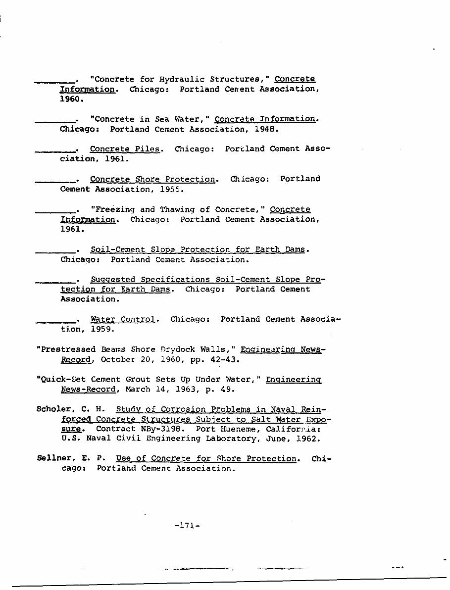
"Concrete for Hydraulic Structures," ConcreteInforp.ation. Chicago: Portland Cenent Association,1960.
". "Concrete in Sea Water," Concrete Information.Chicago: Portland Cement Association, 1948.
__ • Concrete Piles. Chicago: Portland Cement Asso-ciation, 1961.
_ •_ Concrete Shore Protection. Chicago: PortlandCement Association, 1955.
_ ._ "Freezing and Thawing of Concrete," ConcreteInformation. Chicago: Portland Cement Association,1961.
.* Soil-Cement Slope Protection for Earth Dams.Chicago: Portland Cement Association.
_...._. Suggested Specifications Soil-Cement Slope Pro-tection for Earth Dams. Chicago: Portland CementAssociation.
. Water Control. Chicago: Portland Cement Associa-tion, 1959.
"Prestressed Beams Shore Drydock Walls," Engineerincr News-Record, October 20, 1960, pp. 42-43.
"Quick-Vet Cement Grout Sets Up Under Water," EngineeringNews-Record, March 14, 1963, p. 49.
Scholer, C. H. Study of Corrosion Problems in Naval Rein-forced Concrete Structures Subject to Salt Water pxp-sure. Contract NBy-3198. Port Hueneme, California:U.S. Naval Civil Engineering Laboratory, June, 1962.
Sellner, E. P. Use of Concrete for Shore Protection. Chi-cago: Portland Cement Association.
-171-
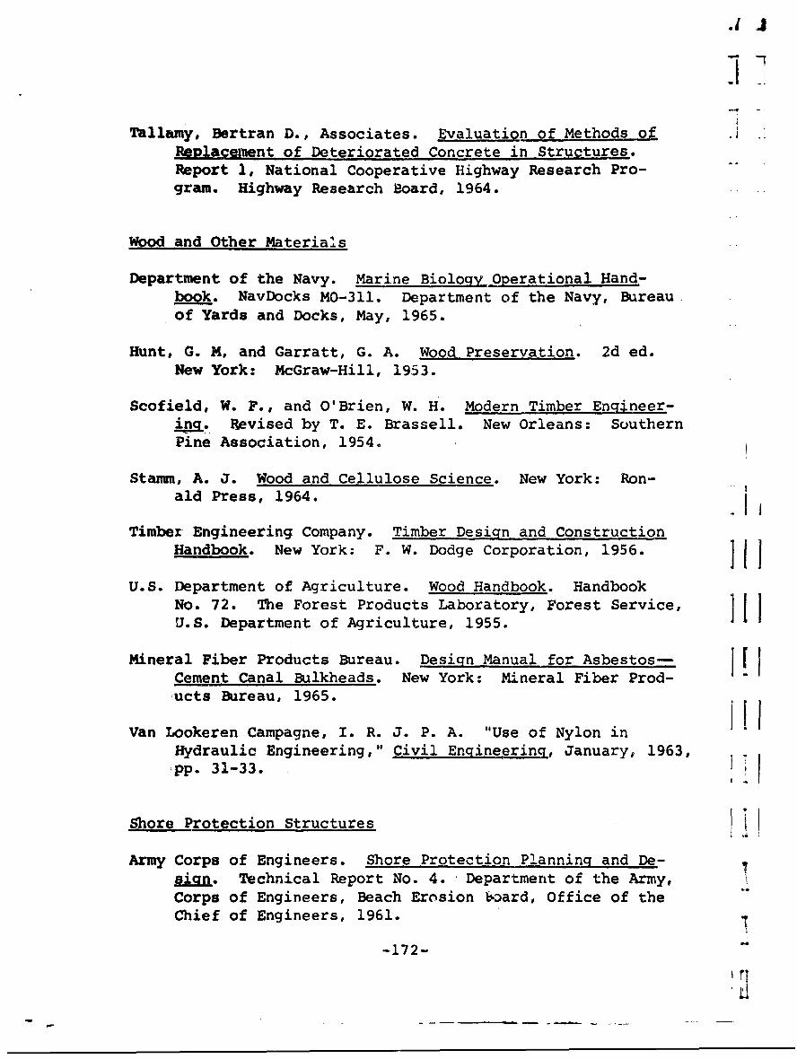
.IJ
Tallamy, Bertran D., Associates. Evaluation of Methods ofReplacement of Deteriorated Concrete in Structures.Report 1, National Cooperative Highway Research Pro-gram. Highway Research Board, 1964.
Wood and Other Material's
Department of the Navy. Marine Biology Operational Hand-book. NavDocks MO-311. Department of the Navy, Bureau.of Yards and Docks, May, 1965.
Hunt, G. M, and Garratt, G. A. Wood Preservation. 2d ed.New York: McGraw-Hill, 1953.
Scofield, W. F., and O'Brien, W. H. Modern Timber Engineer-ia. Revised by T. E. Brassell. New Orleans: SouthernPine Association, 1954.
Stamm, A. J. Wood and Cellulose Science. New York: Ron-ald Press, 1964. - j
Timber Engineering Company. Timber Design and ConstructionHandbook. New York: F. W. Dodge Corporation, 1956. J J
U.S. Department of Agriculture. Wood Handbook. HandbookNo. 72. The Forest Products Laboratory, Forest Service, IU.S. Department of Agriculture, 1955.
Mineral Fiber Products Bureau. Design Manual for Asbestos- I [Cement Canal Bulkheads. New York: Mineral Fiber Prod-ucts Bureau, 1965.
Van Lookeren Campagne, I. R. J. P. A. "Use of Nylon inHydraulic Engineering," Civil Engineering, January, 1963,pp. 31-33. <I
Shore Protection Structures
Army Corps of Engineers. Shore Protection Planning and De-sign. Technical Report No. 4. Department of the Army,Corps of Engineers, Beach Erosion board, Office of theChief of Engineers, 1961.
-172-
'L
California Department of Public Works. Bank and Shore Pro-tection in California Highway Practice. CaliforniaDepartment of Public Works, Division of Highways,November, 1960.
Department of the Navy. Design Manual Waterfront OperationalFacilities. NavDocks DM-25. Updated through February,1966. Department of the Navy, Bureau of Yards and Docks,November, 1961.
_ . Maintenance of Waterfront racilities.NavDocks MO-104. Department of the Navy, Bureau ofYards and Docks.
Hall, Jay V., Jr. "Structure for Shore Protection," CivilEngineering, July, 1963, pp. 38-41.
Minikin, R. R. Winds, Waves, and Maritime Structures.2d ed. London: Griffin, 1963.
Quinn, A. D. Design and Construction of Ports and MarineStructures. New York: McGraw-gill, 1961.
Thorn, R. B. The Design of Sea Defence Works. London:Butterworths, 1960.
Wiegel, R. L. Oceanographical Engineering. Englewood Cliffs,New Jersey: Prentice-Uall, 1964.
Economics and Costs
Brouillette, C. V., and Alumbaugh, R. L. Protective Coatingsfor Steel Piling: Correlation of Results of ParallelTZest Exposures at Port Hueneme and Guam. TechnicalReport R-397. Port Hueneme, California: U.S. NavalCivil Engineering Laboratory, August, 1965.
Grant, E. L. Principles of Engineering Economics. 3d ed.'New York: The Ronald Press Company, 1950.
-173-

King and Gavaris Consulting Engineers. Report of Investirqa-
tion, Existinq Sheet Steel Pile Bulkhead, Naval AirStation1 Floyd Bennett Field. N.Y. Contract NBy 16982(ES).King and Gavaris Consulting Engineers, 30 June 1958,pp. 15-20.
_ _ •& Restudy, Existing Sheet Pile Bulkhead, Naval Air
Station, Floyd Bennett Field, N.Y. Part II. ContractNBy 50996 (A&E). King and Gavaris Consulting Engineers,6 November 1963.
Maguire, Charles A., & Associates. Thames Street RenewalArea Bulkhead Study. 1965, pp. 8-22.
United States Steel Corporation. Mariner Steel Sheet andH Piling. Pittsburgh: United States Steel Corporation,May, 1964, pp. 5-7.
United States Navy. Inspection Reports 1-50. ContractNBy 77539. United States Navy, Eastern Division,Naval Facilities Engineering Command, October, 1966.
Wisconsin Protective Coating Corporation. Corrosion Resist-ant Coating, Bulletin i2. Wisconsin ProtectiveCoating Corporation.
P
-174-w
o* a
eC
ja
t
-174- a
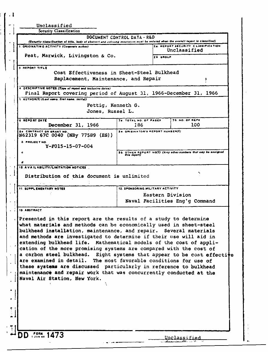
.1
UnclassifiedSecurity Classification
DOCUMENT CONTROL DATA - R&DSeeurttr classlficatioun a title, body of abatrort and ind.iung annotat''n must be entered **on the overall "port i. clesillfed)
I. ORIGINATING ACTIVITY (Corporate auhor) 2s. REPORT 3rCURITY C LASSIFICATION
UnclassifiedPeat, Marwick, Livingston & Co. 2b ooP
3 REPORT TITLE
Cost Effectiveness in Sheet-Steel BulkheadReplacement, Maintenance, and Repair
4 DESCRIPTIVE NOTES (Type of report and Inclusive date&)
Final Report covering period of August 31, 1966-December 31, 19665 AUTHOR(S) (Lest name. heat name, In.iatl)
Fettig, Kenneth G.Jones, Russel L.
6 REPORT DATE ?*. TOTAL NO. OF PAGES OF IFFr
December 31, 1966 186 =00
1a CONTRACT OR GRANT NO. 94. ORIGINATOR'S REPORT NUMBER(S)
N62319 67C 0040 (NBy 77589 (ES))b. PROJU T NO.
Y-F015-15-07-004C. 9Sb. OTHER REPORT NO(S) (Any other numbers that may be assignedthis report)
d.
10. A VAIL AUILITY/LIMITATION NOTICES
Distribution of this document is unlimited
I . SUPPL EMENTANY NOTES 12. SPONSORING, MILITARY ACTIVITY
Eastern DivisionNaval Facilities Eng'g Command
I$. ABSTRACT
Presented tn this reporl; are the results of a study to determinewhat materials and methods can be economically used in sheet-steelbulkhead installation, maintenance, and repair. Several materialsand methods are investigated to determine if their use will aid inextending bulkhead life. Mathematical models of the cost of appli-cation of the more promising systems are compared with the cost ofa carbon steel bulkhead. Eight systems that appear to be cost effecti eare examined in detail. The most favorable conditions for use ofthese systems are discussed particularly in reference to bulkheadmaintenance and repair wbrk that was concurrently conducted at theNaval Air Station, New York.
-f
JDD I JANd 1473 _ Unclassified
Unclassified""SecuityW Clssification
LINK A - LINK . LINK C1_._KEYWORDS _.OLKI WT ROLE WT ROLE WT
Steel Bulkhead'Cost EffectivenessMaintenanceInstallation, BulkheadsRepair, BulkheadsOperations ResearchMethods and Materials
INSTRUCTIONSI. ORIGINATING ACTIVITY: Enter the name and address imposed by security classification, iasing standard statementsof the contractor, subcontractor, grantee, Department of De- such as:fense activity or other organization (corporate author) issuing (1) "Qualified requesters may obtain copies of thisthe report. report from DDC."2a. REPORT SECURTY CLASSIFICATION. Enter the over- (2) "Foreign announcement and dissemination of thisall security classification of the report. Indicate whether"Restricted Data" is Included. Marking is to be in accord- report by DDC is not authorized."ance with appropriate security regulations. (3) "U. S. Government agencies may obtain copies of
this report directly from DDC. Other qualified DDC2b. GROUP: Automatic downgrading is specified in DoD Di- users shall request throughrective 5200. 10 and Armed Forces Industrial Manual. Enterthe group number. Also, when applicable, show that optionalmarkings have been used for Group 3 and Group 4 as author- (4) "U. S. military agencies may obtain copies of thisized. report directly from DDC. Other qualified users3. REPORT TITLE. Entur the complete report title in all shall request throughcapital letters. Titles In all cases should be unclassified.If a meaningful title cannot be selected without classifica-tion. show title classification in all capitals in parenthesis (5) "All distribution of this report is controlled. Qual-immediately following the tit!e. ified DDC users shall request through
4. DESCRIPTIVE NOTES: If appropriate, enter the type of _ __"_
report. e.g., Interim, progress, summary, annual, or final. If the report has been furnished to the Office of TechnicalGive the inclusive dates when a specific reporting period is Services, Department of Commerce, for sale to the public, indi-covered. cate this fact and enter the price, if known.S. AUTHOR(3) Enter the name(s) of author(s) as shown on 11. SUPPLEMENTARY NOTF-' Use for additional explana-or in the report. Entse last name, first name, middle initial, tory notes.If military, show rank and tranch of service. The name ofthe principal author is an absolute minimum teqwurement. 12. SPONSORING MILITARY ACTIVITY: Enter the name of
the departmental project office or laboratory sponsoring (pay6. REPORT DATL. Enter the date of the report as day, inj for) the research and development. Include address.month, year, or month, year. If more than one date appearson the report, use date of publication. 13. ABSTRACT: Enter an abstract giving a brief and factual
summary of the document indicative of the report, even though7&. TOTAL NUMBER OF PAGES The total page count it may also appear elsewhere in the body of the technical re-should follow normal pagination procedures, i.e., enter the port. If additional apace is required, a continuation sheet shallnumber of pages containing information. be attached. s7h. NUMBSER OF REFERENCE& Enter the total number of It is highly desirable that the abstract of classified reportsreferences cited in the report. be unciassifted. Each paragraph of the abstract shall end withBe. CONTRACT OR GRANT NUMBER: If appropriate, enter an indication of the military security classification of the in-the applicable number of the contract or grant under which formation in the paraereph, represented as (TS). (S). (C), o, (U)the report was written. There is no limitation on the length of the abstract. How.8b. 8r, & 8d. PROJECT NUMBER- Enter the appropriate ever, the suggested length is from 150 to 225 words.military department identification, such is project number,subproject number, system numbers, task number, etc. 24. XEY WORDS: Key wurds are technically meaningful terms
or short phrases that characterize a report and may be used as9a. ORIGINATOR'S REPORT NUMBER(S): Enter the off- index entries for cataloging the report. Key words must becias report number by which the document will be identified selected so that no security clarsificjtion is reqjlred. Identi-and controlled by the originating activity. This number mmst fiers, such as equipment model designation, trade name. militarybe unique to this report. project code name, geographic location, may be used as key9b. OTHER REPORT NUMBER(S): If the report has been words but will be foalowed by an indication of technical con-assigned any other report numbers (either by the originator text. The assignment of links, roles. and weights is optional.or by the aponeor), also enter this number(s).
10. AVAiLABILITY/LIMITATION NOTICE& Enter any lim-Listataons on further disseminotion of the report, other than those
Unclassified