corpus christi liquefaction expansion stage 3 project · corpus christi liquefaction expansion –...
TRANSCRIPT

Open House - July 1, 2015
Corpus Christi Liquefaction Expansion – Stage 3 Project

Status of Currently-Authorized Liquefaction Project
FERC authorized the Project on Dec. 30, 2014
Construction at the
Terminal started in Feb. 2015
Pipeline construction
targeted for 2017 Project in service in
2018

Corpus Christi Liquefaction Expansion Stage 3 LNG Facility
• Located within dredged material placement area for currently authorized Liquefaction Project
• Two additional LNG liquefaction trains (five trains total for the two projects)
• One full-containment LNG storage tank (four tanks total for the two projects)
• No new marine facilities
• Increase in LNG vessel calls from 300 to 400 annually

Corpus Christi Liquefaction Expansion Stage 3 Project Schedule
Key Milestone Activities Anticipated Schedule
Beginning of FERC Pre-Filing Process June 2015
Submittal of Natural Gas Act Sections 3 and 7(c) Application January 2016
FERC Issues Authorization of Stage 3 Project March 2017
Commence Terminal Construction May 2017
Commence Pipeline Construction March 2018
Project In Service Early 2021

Corpus Christi Liquefaction Expansion - Stage 3 Project
Corpus Christi Liquefaction Expansion -
Stage 3 Project
Corpus Christi Liquefaction
(Original Project In Construction)

Corpus Christi Liquefaction Expansion Stage 3 Plot Plan

Stage 3 Pipeline
• 22 miles long, 42 inches in diameter
• Parallel to 48-inch diameter pipeline being constructed for currently-authorized
Liquefaction Project
• Will connect
Terminal with
several interstate
and intrastate
pipelines
• Two electric-driven
compressors to be
added to Sinton
Compressor Station
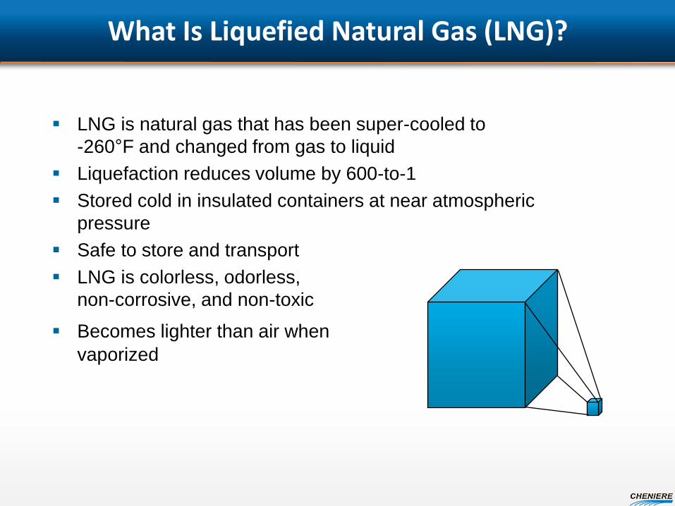
What Is Liquefied Natural Gas (LNG)?
LNG is natural gas that has been super-cooled to
-260°F and changed from gas to liquid
Liquefaction reduces volume by 600-to-1
Stored cold in insulated containers at near atmospheric
pressure
Safe to store and transport
LNG is colorless, odorless,
non-corrosive, and non-toxic
Becomes lighter than air when vaporized
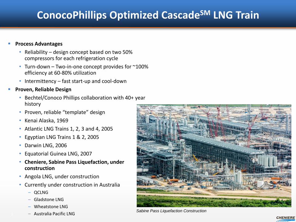
ConocoPhillips Optimized CascadeSM LNG Train
Process Advantages
• Reliability – design concept based on two 50% compressors for each refrigeration cycle
• Turn-down – Two-in-one concept provides for ~100% efficiency at 60-80% utilization
• Intermittency – fast start-up and cool-down
Proven, Reliable Design
• Bechtel/Conoco Phillips collaboration with 40+ year history
• Proven, reliable “template” design
• Kenai Alaska, 1969
• Atlantic LNG Trains 1, 2, 3 and 4, 2005
• Egyptian LNG Trains 1 & 2, 2005
• Darwin LNG, 2006
• Equatorial Guinea LNG, 2007
• Cheniere, Sabine Pass Liquefaction, under construction
• Angola LNG, under construction
• Currently under construction in Australia
– QCLNG
– Gladstone LNG
– Wheatstone LNG
– Australia Pacific LNG
3 Sabine Pass Liquefaction Construction

ConocoPhillips Optimized CascadeSM Process
1. The natural gas is received
at about 1100 psig and 70°F
2. CO2, H2S, water, and
mercury are removed to
prevent freezing and
damage
3. The natural gas is first
cooled to -25°F by a
propane refrigerant
4. Then to -130°F by ethylene
5. Heavy hydrocarbons which
may freeze in the LNG are
removed
6. The final cooling to -215°F
is done by a methane
refrigerant.
7. The LNG is pumped to the
LNG storage tanks where it
is “flashed” down to -256°F.
1
2
3
4
5
7
6

Benefits to the Public Interest
Stimulates local and regional economies • Direct creation of 2,000 to 3,000 engineering and construction jobs
Improves national balance of annual trade by between $9.8B and $15.8B (combined Liquefaction Project and Stage 3 Project)
Supports domestic natural gas productive capacity and promotes stability in natural gas pricing
Promotes liberalization of the global natural gas trade through fostering a global, liquid gas market
Advances national security of U.S. allies through diversification of global natural gas supplies
Potential to displace oil (and coal) for power generation applications, resulting in reduced global CO2 emissions

Stage 3 Project – Minimal Environmental Impacts
Majority of Stage 3 Project LNG Facilities to be developed within dredged material placement area approved for the Liquefaction Project.
Stage 3 Project will share marine facilities with the Liquefaction Project.
No new shoreline impacts. Stage 3 Pipeline to be located parallel to and share right-of-way with
currently authorized pipeline, thereby minimizing project footprint. Stage 3 Pipeline route avoids sensitive habitats. Minimal wetland
impacts. No impacts to Threatened or Endangered Species. No impacts to cultural resources.

LNG Full Containment Storage Tank
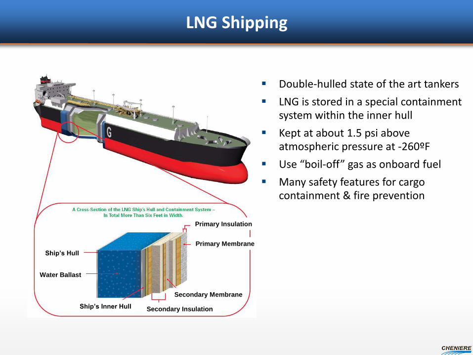
LNG Shipping
Double-hulled state of the art tankers
LNG is stored in a special containment system within the inner hull
Kept at about 1.5 psi above atmospheric pressure at -260ºF
Use “boil-off” gas as onboard fuel
Many safety features for cargo containment & fire prevention
Ship’s Hull
Water Ballast
Ship’s Inner Hull Secondary Insulation
Secondary Membrane
Primary Membrane
Primary Insulation

LNG Safety – Design Parameters
Plant Design
• Materials and equipment selection
• Gas, temperature, UV/IR sensors with automated shutdown
Zero Leak Tolerance
Thermal Exclusion and Vapor Dispersion Zones
• Injurious/hazardous levels contained onsite
Marine Safety/Security Zones
• Prevent collisions with LNG vessels
• Restricted access around LNG vessels
Routine Maintenance
Procedures and Training
• Written operating, safety, security and emergency procedures
Regulations and Oversight
• Oversight both by DOT and FERC
• Routine inspections

C
Western Canada
Northern Rockies
Western Rockies
Green River Basin
Gulf Coast
Eastern U.S.
Permian
Mid Continent
San Juan
East Central Texas
Gulf of Mexico
U.S. Gas Pipeline System Gulf Coast-centered transmission system reaches all US markets
Corpus Christi

FERC is an independent agency that
regulates and oversees energy industries in
the economic and environmental interest of
the American public with the intention of
providing dependable, affordable energy
through sustained competitive markets.
Federal Energy Regulatory Commission:
888 First Street, N.E.
Washington, DC 20426
www.ferc.gov
Public Inquiries
1-866-208-3372
Who Is FERC?