corning one platform
TRANSCRIPT

Corning / Optical Communications / CMA-415-AEN / July 2015 1
Jason GreeneCorning IncorporatedCorning, NY 14831 [email protected]
Robert BasileCorning IncorporatedCorning, NY 14831 [email protected]
R. Todd ChristnerCorning IncorporatedCorning, NY 14831 [email protected]
Corning ONE™ Wireless PlatformAll-Optical Networking Enhanced Performance through Convergence

Corning / Optical Communications / CMA-415-AEN / July 2015 2
The arrival of virtual desktops, managed services, cloud-based computers, wireless, hosted data centers, and a myriad of IP-enabled devices has widely advanced communications and led the way for enterprises to redefine networks. These underlying technologies can make businesses more efficient, advanced, and connected. However, with the advent of new technologies, IT professionals are also finding challenges to support them. While keeping up with business enablement typically requires being at the cusp of the latest and greatest innovations, corporate and IT managers are being asked to do more with less. They are challenged to have ever-evolving networks to support big data analytics and software-enabled solutions, in addition to more devices and more applications.
Over time, enterprises have deployed copper-based LAN networks that were designed originally to support a layered, hierarchical architecture with point-to-point/peer-to-peer connections. As transmission speeds have evolved and wireless has become a more prevalent in-building need, copper-based networks have been ripped and replaced, augmented, and significantly upgraded. In order to respond to this new environment, a different infrastructure approach is needed to make the migration from local user traffic to traffic that flows onto the WAN in a secure, scalable, smart, and more sustainable way.
In the 1980s and 1990s, optical communications revolutionized long-haul transmission. Today, continents are interconnected with undersea fiber optic cables, and across each continent there are terrestrial fiber optic cables forming the communications backbone nationally and regionally in almost every country. Fiber optic technology has shown to be vastly superior to copper in terms of bandwidth, range, consumed power, longevity, security, and reliability. Recent advances in the manufacturing and commercialization of passive and active optical components are extending these capabilities into the horizontal portion of the enterprise network, i.e. to the network edge. Power can now be delivered over composite cable, and pervasive wireless can economically reach every section of a facility. Today’s enterprise networks can cost-effectively use fiber closer to the edge of the network with numerous benefits to the end user. For example, reduced network infrastructure footprint, reduced cost, reduced power requirements, future-ready bandwidth, environmental friendliness, increased security, and increased reliability. As the need for connectivity is ever-increasing, the only requirement moving at a faster rate is the need for mobility. The Corning ONE™ wireless platform addresses these needs head on with the converged network of tomorrow.
Introduction
Figure 1: Evolution to the Corning ONE Wireless Platform
Corning

Corning / Optical Communications / CMA-415-AEN / July 2015 3
This paper will provide a technical review of legacy network architectures deployed today and the benefits of a converged fiber network. This evaluation will look at the following technical considerations: • Device specifications, available content- and application-performance requirements needed to drive the overall network specifications. Important trends to consider include: – Increasing screen size and resolution of devices drive demand for higher-definition media thus higher downlink throughput. – Greater camera resolution and social media-enabled apps drive greater uplink throughput demand. – Storage capacity, CPU, and I/O performance of connected devices such as sensors, high-definition cameras, and mobile devices to enable more complex feature sets. – Cloud-based apps such as video streaming and other social media apps are dependent on network uplink and downlink performance. – A growing number of dual network-capable devices e.g. licensed spectrum networks (cellular) and unlicensed spectrum networks such as Wi-Fi, Bluetooth, etc. • Throughput/bandwidth considerations include: – Network antenna grid/zone spacing throughout large venues should be optimized for both cellular and WLAN 2.4 to 5 GHz. o On the horizon are 900 MHz, white space frequencies, and 60 GHz frequencies for unlicensed use in Wi-Fi. – WLAN design based on guaranteed minimum throughput per device – not theoretical concurrent sessions or advertised physical-layer data rates. WLAN design is not about coverage anymore. It is designed for device throughput needed to perform a function and high availability. • Fiber is preferred over copper due to distance, throughput, EMF interference, weight, and space savings. – TIA/EIA-568 recommends a telecommunications room every 10,000 square ft, at least one per floor, and if connectivity is needed beyond 90 m when deploying copper in the horizontal. – Using fiber to address horizontal connectivity has several benefits: o If an intermediate distribution frame (IDF) has limited space, no space, or does not exist, fiber can extend the access layer out into the horizontal. o Extending the access layer beyond 90 m. o Using fiber to extend the network edge yields space savings in the IDF or eliminates the need for an IDF altogether, allowing the space to be reused to generate revenue, for example. • Supportability: – The copper-to-fiber knowledge gap is shrinking every day. – Advances in fiber manufacturing and technologies now enable better tensile pull strength and bend radius for fiber than Category cabling. – Spectrum monitoring to help troubleshoot real-time issues with network performance. • Hand-off/mobile data session optimization: – Increased sectorization (through smaller zones) as carriers increase capacity. – Mobile network performance requires clean transitions from sector to sector. – Minimize system power levels to only what is required, minimizing noise floor. • Upgradability: – WLAN and cellular standards changing every few years.
Executive Primer
Corning / Optical Communications / CMA-415-AEN / July 2015 4
– New licensed bands for cellular coming via FCC auctions. – Increased optimization of air interface driving greater degrees of MIMO in both WLAN and cellular networks. – Cellular design needs to be based on both current bands with capacity to add future bands 2.1/2.5 GHz, etc. • Future growth/demand: – WLAN road map to 802.11ac, 802.11ad, 802.11ax, 802.11ah, etc. – Advanced LTE (up to 8 x 8 MIMO). – DAS ability to handle future carrier IP-based RF sources – small cell, etc. – Integration of location awareness into building network solution.
Market Trends and Drivers Collection and access to data via a network is driving the marketplace. As the world becomes more connected through the “Internet of Things,” the networks required to support them must evolve as well. If the buildings, homes, and devices we interact with are becoming more intelligent, the networks required to support them must advance as well. Consumer demand to be connected at all times represents only a portion of overall demand. The explosion of connected devices is concerning as they all have a need to interoperate with existing networking infrastructure and systems. The increase in device connectivity will drive automation across many markets. Copper-based enterprise networks are at a tipping point and are outdated to meet these growing business needs. This trend presents five primary problems: • Network connectivity. • Security. • Managing bandwidth. • Future applications and sustainability. • Controlling costs.
The problems above are straining the following networks: local area network (LAN), distributed antenna system (DAS), building management system (BMS), and security/life safety, just to name a few. Traditionally, access to these networks were done through static wired connection, but today better access through mobile and cloud services are required. In order to support future applications, the enterprise market must change rapidly to keep up with the growing user demands surrounding technology and mobility.
Technologies in the local area network (LAN) have slowly evolved over the years to adjust for how data is consumed in various environments across different industry vertical market segments. Ethernet is by far the most prevalent standard utilized today by traditional copper-based switch manufacturers and has been pervasively deployed
Problems in the LAN
The Challenges of Today’s Networks
Corning / Optical Communications / CMA-415-AEN / July 2015 5
for the past 15 to 20 years. Over this time, traffic flows have adjusted from peer-to-peer to more cloud-based computing.
When upgrading network infrastructure, it is important to look at current and future demands. The total cost of ownership (TCO) consists of many challenges and considerations to business owners starting with up-front spend, followed by the drivers of future spend. At the rate Category cabling standards have evolved, IT managers have been in a constant battle with facilities for additional space as well as budget from their financial counterparts to rip and replace every five to seven years. While copper has been an excellent medium over the years, enabling the Ethernet standard to drive today’s traffic flows and business needs, its current application is slowly coming to a halt as it’s expected to do more than it was ever designed for. This expectation includes 10 and 40 Gigabit throughput delivery, ever-growing PoE requirements at the device, as well as distance reach.
Consideration of power consumption, distance, and space for various electronic components along with ancillary gear to support them typically forces businesses to design their buildings around their IT infrastructure, as opposed to designing their IT infrastructure around their building. Copper Ethernet-based LANs require significant consumption of electrical power for the switches/routers in IDF and MDF locations. In addition, signals cannot travel more than 100 m from the switch to the end device over Category cabling without serious degradation. Traditional copper-based networking has a trickle-down effect on many other areas, including power distribution and switch gear, power conversion, and HVAC requirements. Roughly 20 percent of companies now have a dedicated budget allocated for green IT initiatives, and 44 percent say that they are moving toward LEED certifications and sustainability. As LEED initiatives gain traction, traditional LAN design only increases the need to eliminate unwanted, non-renewable plastics and copper in their building cabling designs.
Space is at an all-time premium. As more devices become connected and share a common delivery technology, already full closets are becoming increasingly stressed. Moving across separate vertical market segments, space means different things to each business. In a call center, space means more people answering phones, generating revenue, and/or solving customer issues. In a hospital, space means more critical care beds, and as a result, maximum revenue generation to the business. In hospitality and education, space means more guest/resident rooms and revenue generation. Lastly, in legacy or historic builds, space is nonexistent, forcing IT and facilities to come to odds over what space can be repurposed and allocated to IT. A typical Active Ethernet LAN serving up to 1,000 users requires 45 rack units of space. Active Ethernet LAN switches require one full rack for the switches and two additional racks for terminating the large bundles of copper cables associated with the switches. The total solution would require a total of nine seven-foot-tall equipment racks.
Beyond energy, environmental, and spatial considerations, bandwidth is a top concern as it is consistently looked at as an inexhaustible raw commodity. In actuality, while a sufficient bandwidth pipe is very important, it is equally or more important to consider the efficiency of data delivery as well as how the allocation is managed within the LAN. Active Ethernet suffers from efficiency rates as low as approximately 74 percent due to overhead and latency. Today’s enterprise traffic patterns, fueled by server and data center consolidation, virtual desktop infrastructure (VDI), bring your own device (BYOD), mobile, and cloud computing, are better served by a centralized switch model compared to traditional workgroup technologies with layered active switches. (Source: IBM, 2014)

Corning / Optical Communications / CMA-415-AEN / July 2015 6
When looking at networks from a security standpoint, traditional copper-based Active Ethernet networks stumble in some of the most critical areas. Copper cabling is very susceptible to tapping due to the magnetic field created by signaling on the cable. For these reasons, where data security is a top concern, costly shielded cable must be encased in expensive conduit. In the healthcare industry, when providing connectivity to sensitive equipment such as medical imaging, EMI emissions need to be considered along with security, thus driving requirements for specialized conduit. This conduit from a security perspective is subject to daily inspections in many Department of Defense and top-secret military locations. Traditional Ethernet is also an open standard allowing data to be snooped on the network with readily available tools. There is no built-in encryption mechanism to the base standard of traditional switch manufacturers’ product lines today. Security is not only specific to government applications, but other vertical market segments as well, such as healthcare for HIPAA requirements and the financial industry for wealth management – each places data security as a top priority.
Figure 2: Traditional Three-Tier Switched Ethernet Network Topology
Corning / Optical Communications / CMA-415-AEN / July 2015 7
More and more wireless cellular customers depend on the mobility of their devices wherever they go. Recent growth data confirms the increasing demand for a wide variety of wireless technologies in the indoor space today, especially for DAS.
Venue owners and wireless carriers wishing to provide a satisfying wireless user experience to consumers in vertical market segments such as public venues, healthcare facilities, hospitals, resorts, reception/lobby areas, and hotels realize the importance and need for DAS. Beyond this basic need, there is an ever-growing requirement around design flexibility that allows them to carry a wide range of cellular radio frequencies and technologies.
Both venue owners and cellular providers have been challenged with keeping up with the rapid growth and need for increased throughput at the mobile level. In order to keep up with the demand for more bandwidth at the end device, new technologies have rapidly emerged. This evolution has required costly rip and replace of both infrastructure and electronics, as the need to adopt new methods and technologies have emerged. Examples of this practice can be seen as we consider the recent shifts from 2G to 3G to 4G technologies with 5G around the corner. In only six years we have seen a 25x growth in the consumption of 4G data. (Source: ABI Research, 2013)
The traditional mechanism to solve for the cellular needs in a building is to provide a hybrid fiber coax DAS solution. One such solution involves installing single-mode fiber from a central location in the building to intermediate distribution frame (IDF) closets on each floor. The fiber serves as the RF transport media connecting the DAS electronics in the main distribution frame (MDF) with the RF components in the IDF. Leaving the IDF is a 1/2-in coax cable which goes through a variety of splitters and directional couplers serving antennas throughout the coverage area. The 1/2-in coax is a single-use media used for cellular only within a building. When new carriers join an existing DAS or when carriers change technologies, it requires both new electronics and additional rework of the existing coax splitter infrastructure. This upgrade causes increased cost and disruption to a facility but is needed to keep up with the increasing demand for high-bandwidth cellular.
The Struggle with Distributed Antenna Systems (DAS)
The passive optical local area network (POL) is passive optical network (PON) technology brought into the enterprise LAN through the enhancement of both software and hardware functionality. In a traditional switch-based architecture, multiple tiers of electronics are used to connect users. Ethernet switches in the equipment room are connected via optical fiber to aggregation switches in IDF closets. Individual copper cables extend to each end-user device. In contrast, POL replaces aggregation electronics and associated copper cables with passive optical splitters and single-mode fibers. This creates an architecture that is lower in cost to purchase, install, and maintain – and with a far longer life span – than traditional copper architectures.
What is Passive Optical LAN?
Figure 3: Passive Optical LAN Topologies; Bottom: Multistage Split Layout; Top: Standard 1x32 Split Layout
Corning ONE Wireless Platform is a Converged Solution

Corning / Optical Communications / CMA-415-AEN / July 2015 8
POL is an alternative to the traditional Layer 2 copper-based LAN infrastructure that is designed to support multiple services (e.g. voice, video, and data) at gigabit speeds over single-mode fiber cabling infrastructure. POL overcomes all the limitations found in traditional copper-based Ethernet implementations: the optical fiber cable used in POL can travel for a distance of 12 to 18 miles; the fiber cable structure is much lighter than copper-based cables; the use of bend-insensitive fiber radically diminishes bend radii therefore diminishing cable tray and pathway requirements; the passive nature of the intermediate splitter eliminates the need for power and cooling; the single management console provides consolidated access to all devices and network ports.
Figure 3: Passive Optical LAN Topologies; Bottom: Multistage Split Layout; Top: Standard 1x32 Split Layout
Figure 3 shows the corresponding layers in a traditional LAN architecture. Switches in the access layer and building aggregation layer are replaced by a passive optical splitter, and those two layers no longer exist in a passive optical local area network (POL). The main components of POL architecture are the optical network terminal (ONT), passive splitter, and optical line terminals (OLT). The ONT connects client devices into the POL via the Ethernet ports on the unit. Electrical signals from computer devices get converted to an optical signal in the ONT. Optical splitters simply split the light signal multiple ways to ONTs and transmit the multiplexed signal to the OLT. The OLT aggregates all optical signals from the ONTs and converts them back to electrical signals for the core router. The OLT may also have a range of built-in functionalities such as integrated Ethernet bridging, VLAN capability, end-user authentication, security filtering, etc.
Corning / Optical Communications / CMA-415-AEN / July 2015 9
The Corning ONE wireless platform architecture is entirely fiber-based which provides virtually unlimited bandwidth and significantly enhanced capabilities compared to traditional DAS deployments. Corning leverages expertise in plug-and-play fiber cabling solutions and active optical systems to design a fiber-based DAS solution. • System allows for the rapid deployment of a full-featured DAS supporting increasingly complicated network requirements. • Future-ready architecture allows easy upgrades as carrier requirements shift. • Creates value through enabling new applications, such as WLAN and location services, as well as new remote access node (RAN) solutions, such as remote radio head (RRH) and femtocells, over a common network.
What is Fiber-based Cellular?
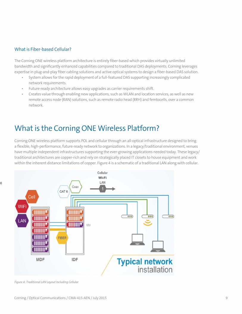
Corning ONE wireless platform supports POL and cellular through an all-optical infrastructure designed to bring a flexible, high-performance, future-ready network to organizations. In a legacy/traditional environment, venues have multiple independent infrastructures supporting the ever-growing applications needed today. These legacy/traditional architectures are copper-rich and rely on strategically placed IT closets to house equipment and work within the inherent distance limitations of copper. Figure 4 is a schematic of a traditional LAN along with cellular.
What is the Corning ONE Wireless Platform?
Figure 4: Traditional LAN Layout Including Cellular
CAT 6cable
Wireless Platform
Corning
*Average when compared to the Corning MobileAccess2000 platform using MobileAccessHX mid-power remotes in a multicarrier, multiband use case in three different vertical market segments.
*
CAT 6
Wi-Fi
Wi-Fi

Corning / Optical Communications / CMA-415-AEN / July 2015 10
Figure 5: Corning ONE Wireless Platform Converged Network Layout
CAT 6cable
Wireless Platform
Corning
*Average when compared to the Corning MobileAccess2000 platform using MobileAccessHX mid-power remotes in a multicarrier, multiband use case in three different vertical market segments.
*
CAT 6
Wi-Fi
Wi-Fi
The Corning ONE wireless platform is the “optical network evolution” of the LAN as it allows for today’s connectivity while simultaneously solving the issues of tomorrow such as mobility, remote powering, and an ever-growing population of connected devices. The extended fiber-rich backbone to the edge enables many networking technologies including Active Ethernet and POL. Deploying POL technology over the Corning ONE wireless platform allows the convergence of many disparate IP-based networks and provides expansion and growth capability in a common single-mode fiber backbone. Architects are able to design a building with a 50 percent reduction in power consumption for the overall network, a permanent reduction in yearly power consumption, with lower installation, maintenance, and equipment cost. This combination also presents the ability to reduce power savings of up to 30 to 65 percent over Active Ethernet solutions, lending itself to green initiatives and reducing total cost of ownership. As enterprises gear to reach environmental goals such as LEED certifications standards, compared to copper mining, fiber is 100 percent more sustainable, as it is manufactured in its entirely from chemical compounds.
Solution Benefits
The Corning ONE wireless platform architecture takes advantage of inherent fiber advantages and extends fiber beyond IT closets into the horizontal space enabling all IT applications for the facility. Because fiber is a universal media and nearly bandwidth-unlimited, it can be used to support both today’s and tomorrow’s technology.

Corning / Optical Communications / CMA-415-AEN / July 2015 11
Passive optical networking has aggressively transitioned over the past five years from the fiber-to-the-home space to the enterprise due to its success in solving many of the problems and limitations discussed earlier for the large carriers of the world. The Corning ONE wireless platform drives fiber deeper into the network while delivering critical services such as cellular and connectivity to the ever-expanding suite of IP-connected devices.
The concept of convergence expands on POL’s fiber-based advantages to bring many benefits to tomorrow’s networks and to drive the TCO model, enabling enterprises to deliver the services their employees and customers demand.
Upgrade cycles are typically dictated by both infrastructure advancements and electronics. Fortunately, single-mode fiber has evolved to a point where it can provide enough bandwidth and durability to boast a 25-year warranty and with a useful expectancy well beyond that. Typically, the cable plant is the most expensive part of a technology upgrade as it requires disruption in typically finished spaces and disruption of service delivery. Installing single-mode fiber removes the requirement for additional upgrades to the cable plant in the foreseeable future and future-readies your network as it has been demonstrated to carry over 100 Tbps of throughput. The next-generation edge electronics upgrade will not impact the installed fiber backbone. This allows for a gradual upgrade of edge and core electronics as required for business-critical applications and a hybrid of technology standards to ride a single medium.
Fiber has typically been relegated to the vertical or riser part of the LAN due to durability and cost concerns. Recent advances in fiber connector technology have reduced the cost of installing fiber significantly, and in most cases the installation of fiber is now less labor-intensive than installation of a copper cable plant. When comparing single-mode fiber to a CAT 5/6/6A copper cable plant, single-mode fiber is smaller, lighter, and stronger. For years, there has been a misconception that fiber is still a very fragile medium. With the release of Corning® ClearCurve® fiber, optical fiber cables now have a smaller bend radius and better tensile pull strength than Category cables. Single-mode fiber also costs significantly less overall in material than CAT 6A.
Both new construction and rehabilitation projects aim for longevity and maximized floor space. Cutting back on floor, rack, and closet space is also extremely important to organizations looking to save in up-front and operational costs. Reduction in floor space lowers future expenses by reducing overhead costs, such as space and HVAC. In addition, the smaller footprint associated with a Corning ONE wireless platform infrastructure enables next-generation performance and services in smaller communication closets not originally designed for many disparate devices. The dense single-mode fiber backbone allows for future services to be delivered to the edge with minimal future spend or disruption to business operations. Additionally, the Corning ONE wireless platform can reach up to 20 km passively allowing fewer communications closets and, in some cases, elimination of them altogether. As a result, a business can recover physical space and cut expenses. Additionally, this reach capability enables an enterprise to deploy POL and DAS headend electronics in a single central location where space is at a far less premium value.
Due to the elimination of electronic switches in intermediate closets, designers and architects can heavily reduce the ancillary gear which enables a traditional LAN. Architects do not have to design the extra power circuits to supply energy to power-hungry workgroup switches and can realize tremendous cost savings eliminating these
Corning / Optical Communications / CMA-415-AEN / July 2015 12
components with the use of POL. In addition, they do not have to design the cooling requirements for IDF closets resulting in the additional power savings from the reduced HVAC equipment. The splitters can be in very small closets on every other floor, or in enclosures behind walls, or mounted in the electrical closets. Required rack space and patch panels are significantly reduced. A POL can serve more than 14,000 IP-addressable devices off a single OLT. Due to the OLT’s 90 percent greater density, this solution requires only one equipment rack and a total of seven to 14 rack units.
POL delivers the most efficient and secure technology available as it attains up to 95 percent bandwidth utilization efficiency and is coupled with strong 128-bit Advanced Encryption Standard (AES) support. Along with being highly secure, the Corning ONE wireless platform infrastructure produces none of the EMI radiation that is typically associated with traditional copper-wired facilities. Utilizing fiber optic cable for the transport mechanism greatly reduces and can effectively remove TEMPEST concerns. In addition, POL provides powerful security measures at the physical layer, data layer, and user port to greatly reduce the potential for malicious attacks. Beyond physical security of the Corning ONE wireless platform infrastructure, POL electronics offer advanced security-focused feature sets including 802.1X, Layer 2-4 ACLs, Sticky MACs, as well as NAC.
A fiber-to-the-edge solution is uniquely capable of meeting the evolving challenges of both wired and wireless deployments and is a true differentiator in the market. As future levels of bandwidth are required, the Corning ONE wireless platform is fully capable of supporting it with no rip and replace. Seamless addition of more technology-based capabilities, such as wavelength division multiplexing, 40- and 100-Gbps transport, and terabyte switching enables the enterprise to significantly reduce the cabling infrastructure costs from the data center to the user by slashing the total number of cable runs and driving fiber to the edge in a point-to-multipoint topology. The result is a decrease in overall operational costs and network complexity.
POL endpoints known as optical network terminals support multiple densities of Gigabit Ethernet, POTS, and RF video. This integrated approach provides the ability to connect building automation systems, security cameras, and building sensors all on the same infrastructure, thereby removing the requirement and expense of separate transport systems through the building and/or campus for each technology.
Flexible “sectorization” and capacity steering of the Corning ONE wireless platform allows the system administrator to manage, extend, change, configure, and optimize the network coverage.
Dedicated and over-provisioned fibers to each antenna location enable • Spare fibers for future growth in wireless and wireline applications. • Highest degree of granularity for 1:1 capacity and location services. • Highest amount of bandwidth for both RF and backhaul connectivity. • Flexible, fully field upgradable, and expandable hot-pluggable modules. • Provide seamless Gigabit Ethernet support with PoE+ (IEEE 802.3at) at the edge.
Corning / Optical Communications / CMA-415-AEN / July 2015 13
www.corning.com
11
A fiber-to-the-edge solution is uniquely capable of meeting the evolving challenges of both wired and wireless deployments and is a true differentiator in the market. As future levels of bandwidth are required, the Corning ONE Wireless Platform is fully capable of supporting it with no rip and replace. Seamless addition of more technology-based capabilities, such as wavelength division multiplexing, 40- and 100-Gbps transport, and terabyte switching enables the enterprise to significantly reduce the cabling infrastructure costs from the data center to the user by slashing the total number of cable runs and driving fiber to the edge in a point-to-multipoint topology. The result is a decrease in overall operational costs and network complexity. POL endpoints known as optical network terminals support multiple densities of Gigabit Ethernet, POTS, and RF video. This integrated approach provides the ability to connect building automation systems, security cameras, and building sensors all on the same infrastructure, thereby removing the requirement and expense of separate transport systems through the building and/or campus for each technology. Flexible “sectorization” and capacity steering of the Corning ONE Wireless Platform allow the system administrator to manage, extend, change, configure, and optimize the network coverage. Dedicated and over-provisioned fibers to each antenna location enables
• Spare fibers for future growth in wireless and wireline applications • Highest degree of granularity for 1:1 capacity and location services • Highest amount of bandwidth for both RF and backhaul connectivity • Flexible, fully field upgradable, and expandable hot-pluggable modules • Provide seamless Gigabit Ethernet support with PoE+ (IEEE 802.3at) at the edge
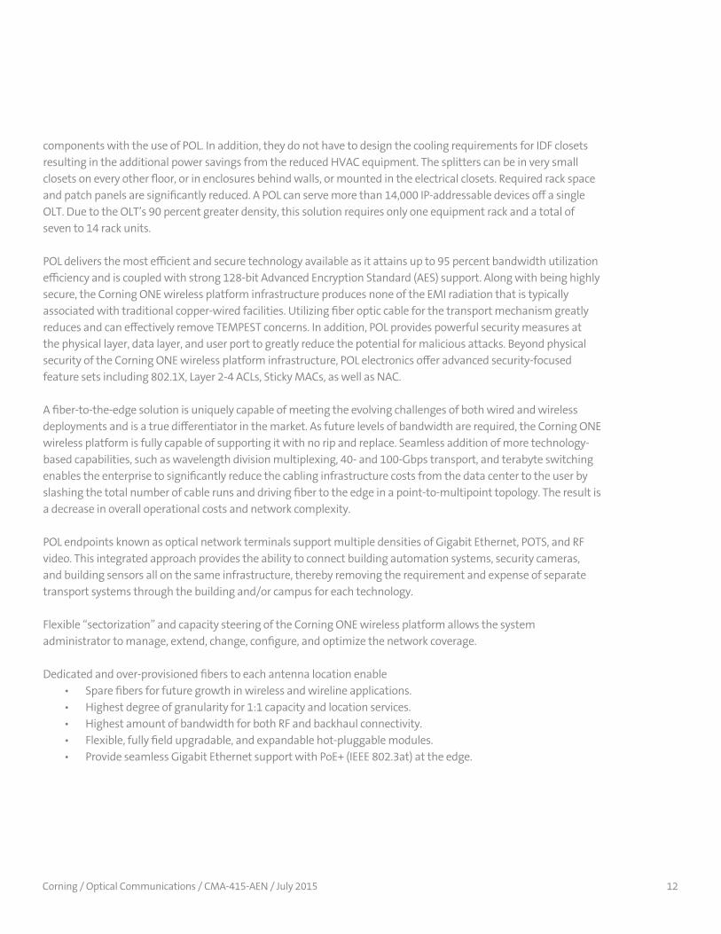
The figure below shows the significant reduction in space and cabling Corning ONE Wireless Platform brings compared to traditional copper and coax DAS deployment.
CE NOTES: Please use “in” instead of inch symbol “ Change ONE Network to Corning ONE Wireless Platform Insert hyphen in caption – “copper-based design”
Figure 6: Cable Comparison and Cable Tray Utilization
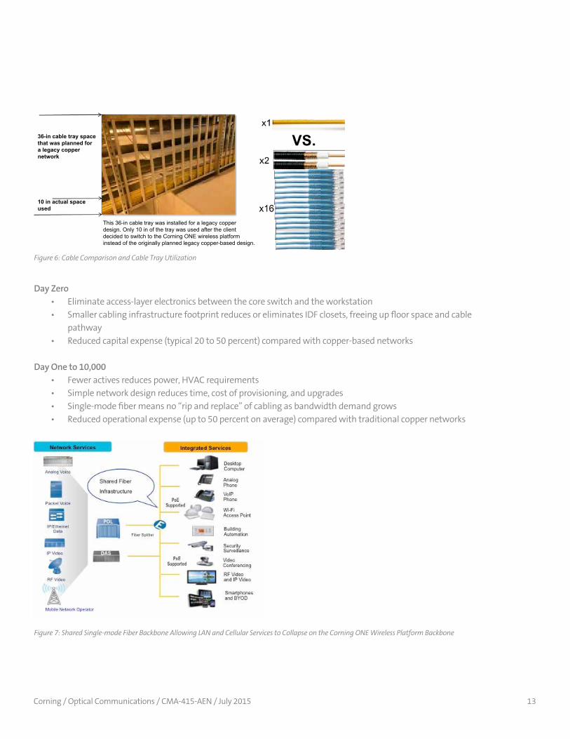
Day Zero • Eliminate access-layer electronics between the core switch and the workstation • Smaller cabling infrastructure footprint reduces or eliminates IDF closets, freeing up floor space and cable pathway • Reduced capital expense (typical 20 to 50 percent) compared with copper-based networks
Day One to 10,000 • Fewer actives reduces power, HVAC requirements • Simple network design reduces time, cost of provisioning, and upgrades • Single-mode fiber means no “rip and replace” of cabling as bandwidth demand grows • Reduced operational expense (up to 50 percent on average) compared with traditional copper networks
Figure 7: Shared Single-mode Fiber Backbone Allowing LAN and Cellular Services to Collapse on the Corning ONE Wireless Platform Backbone
This 36-in cable tray was installed for a legacy copperdesign. Only 10 in of the tray was used after the clientdecided to switch to the Corning ONE wireless platform instead of the originally planned legacy copper-based design.
10 in actual spaceused
36-in cable tray spacethat was planned fora legacy coppernetwork
Corning / Optical Communications / CMA-415-AEN / July 2015 14
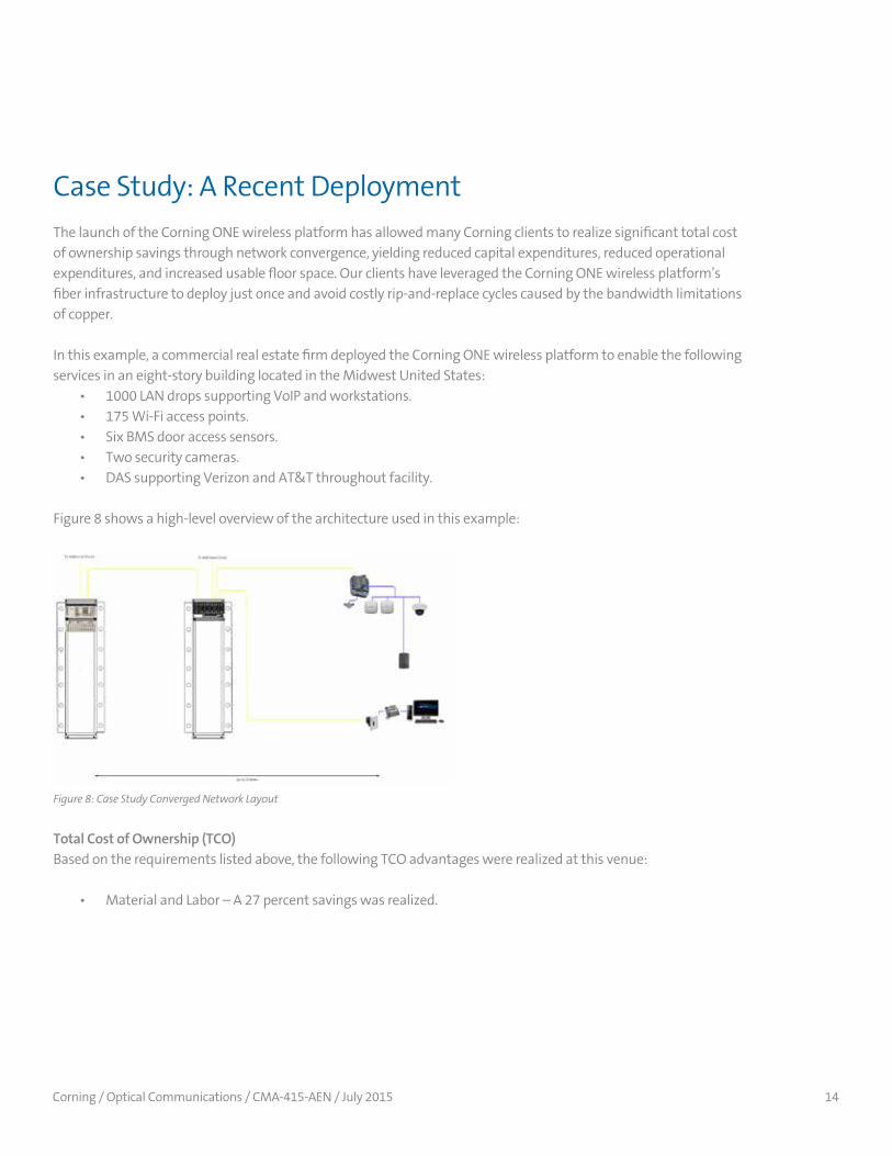
The launch of the Corning ONE wireless platform has allowed many Corning clients to realize significant total cost of ownership savings through network convergence, yielding reduced capital expenditures, reduced operational expenditures, and increased usable floor space. Our clients have leveraged the Corning ONE wireless platform’s fiber infrastructure to deploy just once and avoid costly rip-and-replace cycles caused by the bandwidth limitations of copper.
In this example, a commercial real estate firm deployed the Corning ONE wireless platform to enable the following services in an eight-story building located in the Midwest United States: • 1000 LAN drops supporting VoIP and workstations. • 175 Wi-Fi access points. • Six BMS door access sensors. • Two security cameras. • DAS supporting Verizon and AT&T throughout facility.
Figure 8 shows a high-level overview of the architecture used in this example:
Case Study: A Recent Deployment
Total Cost of Ownership (TCO)Based on the requirements listed above, the following TCO advantages were realized at this venue:
• Material and Labor – A 27 percent savings was realized.
Figure 8: Case Study Converged Network Layout

Corning / Optical Communications / CMA-415-AEN / July 2015 15
www.corning.com
14
Total Cost of Ownership (TCO) Based on the requirements listed above the following TCO advantages were realized at this venue:
• Material and Labor – A 27 percent savings was realized.
CE NOTE: Change “ONE” to Corning ONE Wireless Platform in the drawing above and the one below
• IDF Construction – A 73 percent savings was realized by eliminating 24 IDF closet locations.
Figure 9: Material and Labor Capital Expense Savings*
• IDF Construction – A 73 percent savings was realized by eliminating 24 IDF closet locations.
www.corning.com
14
Total Cost of Ownership (TCO) Based on the requirements listed above the following TCO advantages were realized at this venue:
• Material and Labor – A 27 percent savings was realized.
CE NOTE: Change “ONE” to Corning ONE Wireless Platform in the drawing above and the one below
• IDF Construction – A 73 percent savings was realized by eliminating 24 IDF closet locations.
• Annual Energy OpEx – A 23 percent savings was realized through reduced network and DAS equipment power consumption. This does not take into account the reduced power realized from eliminating cooling in 24 IDF closet locations.
Figure 10: IDF Construction Cost Savings *
Figure 11: Annual Recurring Operational Expense Savings*
CorningONEWirelessPlatform
CorningONEWirelessPlatform
CorningONEWirelessPlatform
www.corning.com
15
• Annual Energy OpEx – A 23 percent savings was realized through reduced
network and DAS equipment power consumption. This does not take into account the reduced power realized from eliminating cooling in 24 IDF closet locations.
CE NOTES: Change “ONE” to Corning ONE Wireless Platform (in the following figure as well) and “Opex” to “OpEx”
• Rack Units – A 57 percent reduction of rack equipment was realized.
Corning ONE Wireless Platform for Tomorrow’s Challenges, Today The most important thing to remember about the Corning ONE Wireless Platform is that it forms the backbone of the building’s data network, similar to the electrical and plumbing network within the building. With a look toward the future, extra fiber and copper pairs can be pre-positioned to enable future applications. When upgrades are needed to the network it becomes a simple exercise in replacing the active electronics on either end. Furthermore, in today’s environment where budgets are constrained, more than ever, capital and operational expenditures are coming under scrutiny. The Corning ONE Wireless Platform succeeds in both capital and operational savings, in most scenarios. Prepare your network for tomorrow’s challenges, today.
OpEx

Corning / Optical Communications / CMA-415-AEN / July 2015 16
www.corning.com
15
• Annual Energy OpEx – A 23 percent savings was realized through reduced
network and DAS equipment power consumption. This does not take into account the reduced power realized from eliminating cooling in 24 IDF closet locations.
CE NOTES: Change “ONE” to Corning ONE Wireless Platform (in the following figure as well) and “Opex” to “OpEx”
• Rack Units – A 57 percent reduction of rack equipment was realized.
Corning ONE Wireless Platform for Tomorrow’s Challenges, Today The most important thing to remember about the Corning ONE Wireless Platform is that it forms the backbone of the building’s data network, similar to the electrical and plumbing network within the building. With a look toward the future, extra fiber and copper pairs can be pre-positioned to enable future applications. When upgrades are needed to the network it becomes a simple exercise in replacing the active electronics on either end. Furthermore, in today’s environment where budgets are constrained, more than ever, capital and operational expenditures are coming under scrutiny. The Corning ONE Wireless Platform succeeds in both capital and operational savings, in most scenarios. Prepare your network for tomorrow’s challenges, today.
• Rack Units – A 57 percent reduction of rack equipment was realized.
Figure 12: Space Savings in Rack Units*
*Case study results compare Corning ONE wireless platform vs. cu-based LAN and HFC DAS.
The most important thing to remember about the Corning ONE wireless platform is that it forms the backbone of the building’s data network, similar to the electrical and plumbing network within the building. With a look toward the future, extra fiber and copper pairs can be pre-positioned to enable future applications. When upgrades are needed to the network it becomes a simple exercise in replacing the active electronics on either end. Furthermore, in today’s environment where budgets are constrained, more than ever, capital and operational expenditures are coming under scrutiny. The Corning ONE wireless platform succeeds in both capital and operational savings, in most scenarios. Prepare your network for tomorrow’s challenges, today.
Corning ONE Wireless Platform for Tomorrow’s Challenges, Today
CorningONEWirelessPlatform
IBM (October 2014). Smarter Networks with Passive Optical LANs Retrieved April 28, 2015 from ibm.com: http://public.dhe.ibm.com/common/ssi/ecm/sf/en/sfw03021usen/SFW03021USEN.PDF
ABI Research ( September 2013). 4G Networks to Handle More Data Traffic Than 3G Networks by 2016 Retrieved July 7, 2015, from ABIresearch.com: www.abiresearch.com/press/4g-networks-to-handle-more-data-traffic- than-3g-ne/
Works Cited
Corning Optical Communications LLC • PO Box 489 • Hickory, NC 28603-0489 USA800-743-2675 • FAX: 828-325-5060 • International: +1-828-901-5000 • www.corning.com/opcommCorning Optical Communications reserves the right to improve, enhance, and modify the features and specifications of Corning Optical Communications products without prior notification. A complete listing of the trademarks of Corning Optical Communications is available at www.corning.com/opcomm/trademarks. All other trademarks are the properties of their respective owners. Corning Optical Communications is ISO 9001 certified. © 2015 Corning Optical Communications. All rights reserved. CMA-415-AEN / July 2015