cordless terminal mobility (ctm); ctm access profile …€¦ · · 2000-02-02cordless terminal...
TRANSCRIPT

Final draft EN 300 824 V1.2.2 (1999-06)European Standard (Telecommunications series)
Digital Enhanced Cordless Telecommunications (DECT);Cordless Terminal Mobility (CTM);
CTM Access Profile (CAP)
ETSI
ETSI Final draft EN 300 824 V1.2.2 (1999-06)2
ReferenceREN/DECT-030139 (7mo00ipc.PDF)
KeywordsCAP, CTM, DECT, synchronization
ETSI
Postal addressF-06921 Sophia Antipolis Cedex - FRANCE
Office address650 Route des Lucioles - Sophia Antipolis
Valbonne - FRANCETel.: +33 4 92 94 42 00 Fax: +33 4 93 65 47 16
Siret N° 348 623 562 00017 - NAF 742 CAssociation à but non lucratif enregistrée à laSous-Préfecture de Grasse (06) N° 7803/88
Individual copies of this ETSI deliverablecan be downloaded from
http://www.etsi.orgIf you find errors in the present document, send your
comment to: [email protected]
Copyright Notification
No part may be reproduced except as authorized by written permission.The copyright and the foregoing restriction extend to reproduction in all media.
© European Telecommunications Standards Institute 1999.All rights reserved.
ETSI
ETSI Final draft EN 300 824 V1.2.2 (1999-06)3
Contents
Intellectual Property Rights................................................................................................................................6
Foreword ............................................................................................................................................................6
1 Scope........................................................................................................................................................7
2 References................................................................................................................................................7
3 Definitions, abbreviations and symbols ...................................................................................................83.1 Definitions ......................................................................................................................................................... 83.2 Abbreviations................................................................................................................................................... 113.3 Symbols ........................................................................................................................................................... 12
4 Introduction............................................................................................................................................12
5 Feature definitions .................................................................................................................................125.1 Network (NWK) features................................................................................................................................. 125.1.1 Application features ................................................................................................................................... 13
6 Service definitions .................................................................................................................................136.1 DLC service definitions ................................................................................................................................... 136.2 Medium Access Control (MAC) service definitions........................................................................................ 13
7 Interoperability requirements.................................................................................................................137.1 General............................................................................................................................................................. 137.2 NWK features .................................................................................................................................................. 147.3 DLC services.................................................................................................................................................... 147.4 MAC services .................................................................................................................................................. 147.5 Physical Layer (PHL) services......................................................................................................................... 147.6 Application features......................................................................................................................................... 147.7 NWK feature to procedure mapping................................................................................................................ 157.8 Service to procedure mapping ......................................................................................................................... 167.8.1 DLC service to procedure mapping............................................................................................................ 167.8.2 MAC service to procedure mapping........................................................................................................... 167.8.3 Application feature to procedure mapping ................................................................................................. 167.9 General requirements ....................................................................................................................................... 177.9.1 Coexistence of MM and CC procedures .................................................................................................... 17
8 Procedure description.............................................................................................................................17
9 NWK layer procedures...........................................................................................................................189.1 External handover procedures.......................................................................................................................... 189.1.1 Handover candidate procedure................................................................................................................... 189.1.1.1 Handover candidate indication ............................................................................................................. 189.1.1.2 Handover candidate retrieval................................................................................................................ 199.1.1.2.1 Exceptional cases ............................................................................................................................ 209.1.1.2.1.1 Failure of the PP handover candidate retrieval attempt ............................................................. 209.1.2 Target FP selection..................................................................................................................................... 209.1.3 Handover reference procedure ................................................................................................................... 219.1.3.1 Handover reference indication.............................................................................................................. 219.1.3.2 Handover reference retrieval ................................................................................................................ 219.1.3.2.1 Exceptional cases ............................................................................................................................ 229.1.3.2.1.1 Failure of the PP handover reference retrieval attempt ............................................................. 229.1.4 External handover call set-up ..................................................................................................................... 239.1.4.1 Associated procedures .......................................................................................................................... 239.1.4.1.1 Transaction identifier handling ....................................................................................................... 239.1.4.2 Exceptional cases.................................................................................................................................. 239.1.4.2.1 Abnormal link release on FP-1 leg.................................................................................................. 239.1.4.2.2 Normal call release on FP-2 leg ...................................................................................................... 239.1.4.2.3 Abnormal link release on FP-2 leg.................................................................................................. 239.1.5 Ciphering procedure................................................................................................................................... 24
ETSI
ETSI Final draft EN 300 824 V1.2.2 (1999-06)4
9.1.5.1 Ciphering procedure PT initiated.......................................................................................................... 249.1.5.2 Ciphering procedure FT initiated.......................................................................................................... 249.1.6 U-plane handling ........................................................................................................................................ 249.2 Emergency call set-up...................................................................................................................................... 249.3 Display............................................................................................................................................................. 259.4 Terminal capability indication ......................................................................................................................... 259.5 Detach.............................................................................................................................................................. 269.6 Enhanced location registration......................................................................................................................... 269.6.1 Exceptional case(s)..................................................................................................................................... 279.6.1.1 Failure of location registration procedure............................................................................................. 279.7 Message waiting indication.............................................................................................................................. 279.7.1 MWIIndicate- activation ............................................................................................................................ 289.7.2 MWIIndicate- deactivation ........................................................................................................................ 299.7.3 Retrieval of the message............................................................................................................................. 299.8 On-air modification of user parameters ........................................................................................................... 299.8.1 Exceptional cases ....................................................................................................................................... 309.8.1.1 Collision with normal call procedure.................................................................................................... 30
10 DLC layer procedures ............................................................................................................................30
11 MAC layer procedures ...........................................................................................................................3011.1 General............................................................................................................................................................. 3011.2 Downlink broadcast ......................................................................................................................................... 3111.3 Non-continuous broadcast ............................................................................................................................... 3111.3.1 Mt message................................................................................................................................................. 3211.3.1.1 Extended system information................................................................................................................ 3211.3.1.2 TARI message ...................................................................................................................................... 3211.4 RFP status ........................................................................................................................................................ 3311.4.1 RFP status information............................................................................................................................... 3311.5 Extended fixed part capabilities....................................................................................................................... 3411.6 Prolonged preamble ......................................................................................................................................... 3411.6.1 Procedure for prolonged preamble diversity in RFP and prolonged preamble transmission in PP ............ 3411.6.2 Procedure for prolonged preamble diversity in PP and prolonged preamble transmission in RFP ............ 34
12 Physical layer requirements ...................................................................................................................3412.1 General............................................................................................................................................................. 3412.2 External handover ............................................................................................................................................ 3512.3 Prolonged Preamble......................................................................................................................................... 35
13 Requirements regarding the speech transmission ..................................................................................3513.1 General............................................................................................................................................................. 3513.2 Reference to GAP ............................................................................................................................................ 35
14 Management procedures ........................................................................................................................3514.1 General............................................................................................................................................................. 3514.2 Location registration initiation......................................................................................................................... 3514.3 Assigned individual Temporary Portable User Identity (TPUI) management ................................................. 3614.4 Detach.............................................................................................................................................................. 3614.5 External handover ............................................................................................................................................ 3614.6 Emergency call management............................................................................................................................ 3714.7 PMID management .......................................................................................................................................... 3714.8 Broadcast attributes management .................................................................................................................... 3714.9 Message waiting indication.............................................................................................................................. 38
15 Application procedures ..........................................................................................................................3815.1 General............................................................................................................................................................. 3815.2 Subscription control......................................................................................................................................... 38
ETSI
ETSI Final draft EN 300 824 V1.2.2 (1999-06)5
Annex A (normative): System parameters ........................................................................................39
A.1 NWK layer constants .............................................................................................................................39
A.2 PHL constants ........................................................................................................................................39
Annex B (informative): PP locking procedure for on air subscription.............................................40
Annex C (informative): Void.................................................................................................................41
Annex D (informative): Tones, progress indicator and U-plane connection ....................................42
Annex E (informative): PARI and SARI use for CTM roaming.......................................................43
Annex F (normative): Class 2 synchronization requirements.........................................................45
Annex G (normative): Synchronization requirements for fixed parts............................................46
Annex H (informative): Coding example for message waiting indication ........................................47
Bibliography.....................................................................................................................................................48
History..............................................................................................................................................................49
ETSI
ETSI Final draft EN 300 824 V1.2.2 (1999-06)6
Intellectual Property RightsIPRs essential or potentially essential to the present document may have been declared to ETSI. The informationpertaining to these essential IPRs, if any, is publicly available for ETSI members and non-members, and can be foundin SR 000 314: "Intellectual Property Rights (IPRs); Essential, or potentially Essential, IPRs notified to ETSI in respectof ETSI standards", which is available free of charge from the ETSI Secretariat. Latest updates are available on theETSI Web server (http://www.etsi.org/ipr).
Pursuant to the ETSI IPR Policy, no investigation, including IPR searches, has been carried out by ETSI. No guaranteecan be given as to the existence of other IPRs not referenced in SR 000 314 (or the updates on the ETSI Web server)which are, or may be, or may become, essential to the present document.
ForewordThis European Standard (Telecommunications series) has been produced by ETSI Project Digital Enhanced CordlessTelecommunications (DECT), and is now submitted for the Voting phase of the ETSI standards Two-step ApprovalProcedure.
The present document is based on EN 300 175, parts 1 to 8 [1] to [8] and EN 300 444 [12].
Proposed national transposition dates
Date of latest announcement of this EN (doa): 3 months after ETSI publication
Date of latest publication of new National Standardor endorsement of this EN (dop/e): 6 months after doa
Date of withdrawal of any conflicting National Standard (dow): 6 months after doa
ETSI
ETSI Final draft EN 300 824 V1.2.2 (1999-06)7
1 ScopeThe present document specifies that set of technical requirements for Digital Enhanced Cordless Telecommunications(DECT) Fixed Part (FP) and DECT Portable Part (PP) necessary for the support of the Cordless Terminal Mobility(CTM) Access Profile (CAP).
The objective of the present document is to ensure the air interface interoperability of DECT CAP PPs and DECT CAPFPs if applied.
The CTM service allows users of cordless terminals to be mobile within and between networks. Where radio coverage isprovided and the cordless terminal has appropriate access rights the user shall be able to make calls from, and to receivecalls at, any location within the fixed public and/or private networks, and may move without interruption of a call inprogress.
The present document covers the DECT access requirements for CTM phase 2 as defined in the CTM phase 2 servicedescription, EN 301 273 [14].
The main objectives of the CAP are:
- maintain compatibility with the DECT Generic Access Profile (GAP), identifying only components notmandatory in the GAP to be added to obtain capabilities needed in the CTM context;
- maintain compatibility with EN 300 175 parts 1 to 8 [1] to [8], for procedures not defined in the GAP.
The CTM access profile is seen as an extension of the GAP mandatory base covering the requirements for CTMphase 2.
CAP supports telephony teleservice and provides 32 kbit/s Adaptive Differential Pulse Code Modulation (ADPCM)speech bearer service.
CTM supplementary services with no impact on the air interface are not considered in the CAP.
2 ReferencesThe following documents contain provisions which, through reference in this text, constitute provisions of the presentdocument.
• References are either specific (identified by date of publication, edition number, version number, etc.) ornon-specific.
• For a specific reference, subsequent revisions do not apply.
• For a non-specific reference, the latest version applies.
• A non-specific reference to an ETS shall also be taken to refer to later versions published as an EN with the samenumber.
[1] EN 300 175-1: "Digital Enhanced Cordless Telecommunications (DECT); Common Interface (CI);Part 1: Overview".
[2] EN 300 175-2: "Digital Enhanced Cordless Telecommunications (DECT); Common Interface (CI);Part 2: Physical layer (PHL)".
[3] EN 300 175-3: "Digital Enhanced Cordless Telecommunications (DECT); Common Interface (CI);Part 3: Medium Access Control (MAC) layer".
[4] EN 300 175-4: "Digital Enhanced Cordless Telecommunications (DECT); Common Interface (CI);Part 4: Data Link Control (DLC) layer".
[5] EN 300 175-5: "Digital Enhanced Cordless Telecommunications (DECT); Common Interface (CI);Part 5: Network (NWK) layer".
ETSI
ETSI Final draft EN 300 824 V1.2.2 (1999-06)8
[6] EN 300 175-6: "Digital Enhanced Cordless Telecommunications (DECT); Common Interface (CI);Part 6: Identities and addressing".
[7] EN 300 175-7: "Digital Enhanced Cordless Telecommunications (DECT); Common Interface (CI);Part 7: Security features".
[8] EN 300 175-8: "Digital Enhanced Cordless Telecommunications (DECT); Common Interface (CI);Part 8: Speech coding and transmission".
[9] ETS 300 176: "Digital Enhanced Cordless Telecommunications (DECT); Approval testspecification".
[10] TBR 6: "Digital Enhanced Cordless Telecommunications (DECT); General terminal attachmentrequirements".
[11] TBR 10 (1997): "Digital Enhanced Cordless Telecommunications (DECT); General terminalattachment requirements; Telephony applications".
[12] EN 300 444: "Digital European Cordless Telecommunications (DECT); Generic Access Profile(GAP)".
[13] TBR 22: "Radio Equipment and Systems (RES); Attachment requirements for terminal equipmentfor Digital Enhanced Cordless Telecommunications (DECT) Generic Access Profile (GAP)applications".
[14] EN 301 273: "Cordless Terminal Mobility (CTM); Phase 2 Service description".
[15] EN 300 745-1: "Integrated Services Digital Network (ISDN); Message Waiting Indication (MWI)supplementary service; Digital Subscriber Signalling System No. one (DSS1) protocol; Part 1:Protocol specification".
[16] ISO/IEC 9646-7 (1995): "Information technology - Open Systems Interconnection - Conformancetesting methodology and framework - Part 7: Implementation Conformance Statements".
[17] EN 300 196-1: "Integrated Services Digital Network (ISDN); Generic functional protocol for thesupport of supplementary services; Digital Subscriber Signalling System No. one (DSS1) protocol;Part 1: Protocol specification".
3 Definitions, abbreviations and symbols
3.1 DefinitionsFor the purposes of the present document, the following terms and definitions apply:
attach: process whereby a PP within the coverage area of a FP to which it has access rights, notifies this FP that it isoperative. The reverse process is detach, which reports the PP as inoperative.
NOTE 1: An operative PP is assumed to be ready to receive calls.
authentication: process whereby a CTM subscriber is positively verified to be a legitimate user of the CTM service.
NOTE 2: Authentication is generally performed at call set-up, but may also be done at any other time (e.g. duringa call).
bearer service: type of telecommunication service that provides a defined capability for the transmission of signalsbetween user-network interfaces.
NOTE 3: The DECT user-network interface corresponds to the top of the network layer (layer 3).
ETSI
ETSI Final draft EN 300 824 V1.2.2 (1999-06)9
C-plane: control plane of the DECT protocol stacks, which contains all of the internal DECT protocol control, but mayalso include some external user information.
NOTE 4: The C-plane stack always contains protocol entities up to and including the network layer.
call: all of the Network (NWK) layer processes involved in one network layer peer-to-peer association.
NOTE 5: Call may sometimes be used to refer to processes of all layers, since lower layer processes are implicitlyrequired.
DECT network: network that uses the DECT air interface to interconnect a local network to one or more portableapplications. The logical boundaries of the DECT network are defined to be at the top of the DECT network layer.
NOTE 6: A DECT network is a logical grouping that contains one or more fixed radio terminations plus theirassociated portable radio termination. The boundaries of the DECT network are not physicalboundaries.
external handover: process of switching a call in progress from one fixed part to another fixed part.
Fixed Part (DECT Fixed Part) (FP): physical grouping that contains all of the elements in the DECT network betweenthe local network and the DECT air interface.
NOTE 7: A DECT FP contains the logical elements of at least one FT, plus additional implementation specificelements.
Fixed radio Termination (FT): logical group of functions that contains all of the DECT processes and procedures onthe fixed side of the DECT air interface.
NOTE 8: A FT only includes elements that are defined in the DECT Common Interface (CI) standard. Thisincludes radio transmission elements together with a selection of layer 2 and layer 3 elements.
geographically unique identity: term relates to FP identities, Primary Access Rights Identities (PARIs) and RadioFixed Part Identities (RFPIs). It indicates that two systems with the same PARI, or respectively two Radio Fixed Parts(RFPs) with the same RFPI, can not be reached or listened to at the same geographical position.
NOTE 9: For PARI and RFPI see abbreviations.
global network: telecommunication network capable of offering a long distance telecommunication service.
NOTE 10: The term does not include legal or regulatory aspects, nor does it indicate if the network is a public or aprivate network.
globally unique identity: identity is unique within DECT (without geographical or other restrictions).
handover: process of switching a call in progress from one physical channel to another physical channel.
NOTE 11: There are two physical forms of handover, intra-cell handover and inter-cell handover.
incoming call: call received at a PP.
inter-cell handover: switching of a call in progress from one cell to another cell.
internal handover: handover processes that are completely internal to one FT. Internal handover reconnects the call atthe lower layers, while maintaining the call at the NWK layer.
NOTE 12: The lower layer reconnection can either be at the Data Link Control (DLC) layer (connection handover)or at the MAC layer (bearer handover).
interoperability: capability of FPs and PPs, that enable a PP to obtain access to teleservices in more than one locationarea and/or from more than one operator (more than one service provider).
interoperator roaming: roaming between FP coverage areas of different operators (different service providers).
ETSI
ETSI Final draft EN 300 824 V1.2.2 (1999-06)10
Interworking Unit (IWU): unit that is used to interconnect sub networks.
NOTE 13: The IWU will contain the interworking functions necessary to support the required sub networkinterworking.
intra-cell handover: switching of a call in progress from one physical channel of one cell to another physical channel ofthe same cell.
intraoperator roaming: roaming between different FP coverage areas of the same operator (same service provider).
Local Network (LNW): telecommunication network capable of offering local telecommunication services.
NOTE 14: The term does not include legal or regulatory aspects, nor does it indicate if the network is a publicnetwork or a private network.
locally unique identity: unique identity within one FP or location area, depending on application.
location area: domain in which a PP may receive (and/or make) calls as a result of a single location registration.
location registration: process whereby the position of a DECT PT is determined to the level of one location area, andthis position is updated in one or more databases.
NOTE 15: These databases are not included within a DECT FT.
MAC Connection (CONNECTION): association between one source MAC Multi-Bearer Control (MBC) entity andone destination Medium Access Control (MAC) Multi-Bearer Control (MBC) entity. This provides a set of relatedMAC services (a set of logical channels), and it can involve one or more underlying MAC bearers.
outgoing call: call originating from a PP.
Portable Application (PA): logical grouping that contains all the elements that lie beyond the DECT network boundaryon the portable side.
NOTE 16: The functions contained in the PA may be physically distributed, but any such distribution is invisible tothe DECT network.
Portable Part (DECT Portable Part) (PP): physical grouping that contains all elements between the user and theDECT air interface. PP is a generic term that may describe one or several physical pieces.
NOTE 17: A DECT PP is logically divided into one PT plus one or more PAs.
Portable radio Termination (PT): logical group of functions that contains all of the DECT processes and procedureson the portable side of the DECT air interface.
NOTE 18: A PT only includes elements that are defined in the DECT CI standard. This includes radio transmissionelements (layer 1) together with a selection of layer 2 and layer 3 elements.
Radio Fixed Part (RFP): one physical sub-group of a FP that contains all the radio end points (one or more) that areconnected to a single system of antennas.
roaming: movement of a PP from one FP coverage area to another FP coverage area, where the capabilities of the FPsenable the PP to make or receive calls in both areas.
NOTE 19: Roaming requires the relevant FPs and PP to be interoperable.
subscription registration: infrequent process whereby a subscriber obtains access rights to one or more FPs.
NOTE 20: Subscription registration is usually required before a user can make or receive calls.
supplementary service: service that modifies or supplements a basic telecommunications service.
teleservice: type of telecommunications service that provides the complete capability, including terminal equipmentfunctions, for communication between users, according to protocols that are established by agreement.
ETSI
ETSI Final draft EN 300 824 V1.2.2 (1999-06)11
3.2 AbbreviationsFor the purposes of the present document, the following abbreviations apply:
ADPCM Adaptive Differential Pulse Code ModulationARC Access Rights ClassARD Access Rights DetailsARI Access Rights IdentityCAP CTM Access ProfileCC Call ControlCI Common InterfaceCLIP Calling Line Identification PresentationCTM Cordless Terminal MobilityDECT Digital Enhanced Cordless TelecommunicationsDLC Data Link ControlEMC Equipment Manufacturer CodeFP Fixed PartFT Fixed radio TerminationGAP Generic Access ProtocolIE Information ElementIPEI International Portable Equipment IdentityIPUI International Portable User IdentityISDN Integrated Services Digital NetworkIWU Interworking UnitLA Location AreaLAI Location Area IdentificationLAL Location Area LevelLCE Link Control EntityLNW Local NetworkMAC Medium Access ControlMBC Multi-Bearer ControlMM Mobility Management, a NWK layer functional groupingMWI Message Waiting IndicationNWK Network, Layer 3 of the DECT protocol stackP Public (environment)PA Portable ApplicationPARI Primary Access Rights IdentityPARK Portable Access Rights KeyPHL Physical LayerPLI Park Length IndicatorPMID Portable part MAC IdentityPP Portable PartPSN Portable equipment Serial NumberPT Portable radio TerminationPUN Portable User NumberPUT Portable User TypeRES A Response calculated by a PPRFP Radio Fixed PartRFPI Radio Fixed Part IdentitySAP Service Access PointSARI Secondary Access Rights IdentityTARI Tertiary Access Rights IdentityTPUI Temporary Portable User Identity
ETSI
ETSI Final draft EN 300 824 V1.2.2 (1999-06)12
3.3 SymbolsThe symbols defined in this subclause are applied for procedures, features, services in the present document if notexplicitly otherwise stated. The interpretation of status columns in all tables is as follows:
M for mandatory to support (provision mandatory, process mandatory)O for optional to support (provision optional, process mandatory)I for out-of-scope (provision optional, process optional) not subject for testingC for conditional to support (process mandatory)N/A for not-applicable (in the given context the specification makes it impossible to use this capability)
Provision mandatory, process mandatory means that the indicated feature, service or procedure shall be implemented asdescribed in the present document, and may be subject to testing.
Provision optional, process mandatory means that the indicated feature, service or procedure may be implemented, andif implemented, the feature, service or procedure shall be implemented as described in the present document, and maybe subject to testing.
NOTE: The used notation is based on the notation proposed in ISO/IEC 9646-7 [16].
4 IntroductionThis profile is an extension of EN 300 444 [12] covering the requirements for CTM phase 2.
In the following clauses only differences with respect to EN 300 444 [12] are explicitly mentioned.
5 Feature definitionsFor the purposes of the present document, the feature definitions in the following subclauses apply.
The reference given in parentheses after the name of a feature is the item reference used in the tables of the presentdocument.
5.1 Network (NWK) featuresThe following differences from the GAP are applicable.
DECT external handover (CAP-N.1): External handover is the process of switching a call in progress from one FixedPart (FP-1) to another Fixed Part (FP-2). This means the handover occurs between two independent systems, where eachsystem has its own lower layers of protocol and has an independent set of network layer Service Access Points (SAPs).To make external handover possible, a common management entity above the two fixed terminations is necessary.
Emergency call (CAP-N.2): This service feature enables a user to make an emergency call even without a validsubscription, i.e. a fast and easy means of giving information about an emergency situation to the appropriate emergencyorganization (e.g. fire service, police and ambulance).
Display management (CAP-N.3): This feature enables a user to receive short alphanumeric indications displayed onthe screen terminal. These indications could be associated with supplementary or value added services.
Message waiting indication (CAP-N.4): This feature enables a user to receive an indication of the status of a messageserver (e.g. a voice mailbox) to which the user has access to.
Detach (CAP-N.5): This feature enables a PT to report to the FT that the PT is not ready to receive calls.
Enhanced location registration (CAP-N.6): This feature enables automatic location registration of PT at expectedintervals of time.
On-air modification of user parameters (CAP-N.7): This feature enables the FT to modify the active subscriptiondata of the PT.
ETSI
ETSI Final draft EN 300 824 V1.2.2 (1999-06)13
5.1.1 Application features
See EN 300 444 [12].
6 Service definitionsFor the purposes of the present document, the following service definitions apply.
6.1 DLC service definitionsSee EN 300 444 [12].
6.2 Medium Access Control (MAC) service definitionsThe following differences from the GAP are applicable.
Tertiary Access Rights Identity (TARI) support (CAP-M.1): The ability to support in addition to the primary AccessRights Identity (ARI) and secondary ARIs tertiary ARIs that the FT does not broadcast and are only available to PT as aYes/No answer upon a request including the wanted ARI. These may be used to reflect an inter-operators agreementallowing a portable to access more than one operator or services through FT.
RFP status (CAP-M.2): A service which indicates to the PP the status (busy or clear) of the RFP or the system (FP).
Extended fixed part capabilities (CAP-M.3): A service which indicates to the PP the extended capabilities of the FP.
Prolonged preamble diversity in RFP (CAP-M.4): The ability of the RFP to support antenna diversity based on thereception of a prolonged preamble.
Prolonged preamble diversity in PP (CAP-M.5): The ability of the PP to support antenna diversity based on thereception of a prolonged preamble.
Prolonged preamble transmission of the RFP (CAP-M.6): The ability of the RFP to transmit prolonged preamble ifthe PP supports prolonged preamble diversity.
Prolonged preamble transmission of the PP (CAP-M.7): The ability of the PP to transmit prolonged preamble if theRFP supports prolonged preamble diversity.
7 Interoperability requirements
7.1 GeneralThe tables listed in this subclause define all the protocol elements i.e. features, services, and procedures which aremandatory, optional, and conditional under the provision of another protocol element, or out of the scope of the presentdocument, or in some context not-applicable according to the definition of the status column as defined in subclause 3.3for the CAP FP and PP. All optional elements shall be process mandatory according to the procedures described in thepresent document.
Protocol elements defined as mandatory, optional or conditional in this subclause shall further be defined in clauses 8, 9,10, 11, 12, 13, 14 and 15 in detail either explicitly and/or as references to the DECT base standard, EN 300 175parts 2 to 8, [2] to [8] and ETS 300 176 [9].
The requirements of TBR 6 [10], TBR 10 [11] and TBR 22 [13] shall be met by all equipment conforming to the presentdocument.
ETSI
ETSI Final draft EN 300 824 V1.2.2 (1999-06)14
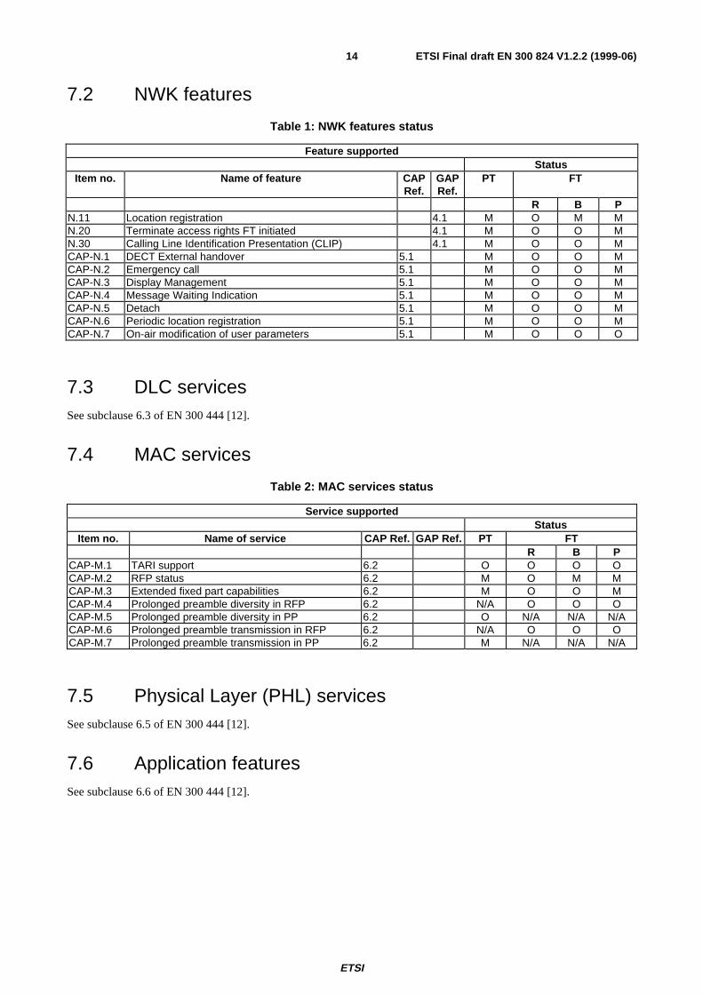
7.2 NWK features
Table 1: NWK features status
Feature supportedStatus
Item no. Name of feature CAPRef.
GAPRef.
PT FT
R B PN.11 Location registration 4.1 M O M MN.20 Terminate access rights FT initiated 4.1 M O O MN.30 Calling Line Identification Presentation (CLIP) 4.1 M O O MCAP-N.1 DECT External handover 5.1 M O O MCAP-N.2 Emergency call 5.1 M O O MCAP-N.3 Display Management 5.1 M O O MCAP-N.4 Message Waiting Indication 5.1 M O O MCAP-N.5 Detach 5.1 M O O MCAP-N.6 Periodic location registration 5.1 M O O MCAP-N.7 On-air modification of user parameters 5.1 M O O O
7.3 DLC servicesSee subclause 6.3 of EN 300 444 [12].
7.4 MAC services
Table 2: MAC services status
Service supportedStatus
Item no. Name of service CAP Ref. GAP Ref. PT FTR B P
CAP-M.1 TARI support 6.2 O O O OCAP-M.2 RFP status 6.2 M O M MCAP-M.3 Extended fixed part capabilities 6.2 M O O MCAP-M.4 Prolonged preamble diversity in RFP 6.2 N/A O O OCAP-M.5 Prolonged preamble diversity in PP 6.2 O N/A N/A N/ACAP-M.6 Prolonged preamble transmission in RFP 6.2 N/A O O OCAP-M.7 Prolonged preamble transmission in PP 6.2 M N/A N/A N/A
7.5 Physical Layer (PHL) servicesSee subclause 6.5 of EN 300 444 [12].
7.6 Application featuresSee subclause 6.6 of EN 300 444 [12].
ETSI
ETSI Final draft EN 300 824 V1.2.2 (1999-06)15
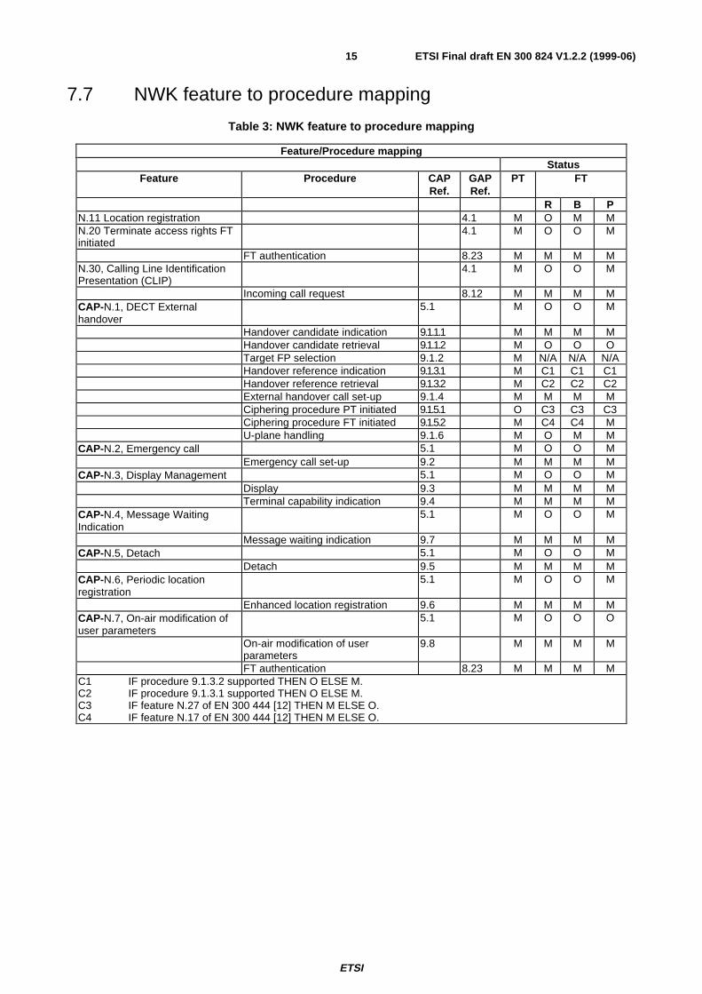
7.7 NWK feature to procedure mapping
Table 3: NWK feature to procedure mapping
Feature/Procedure mappingStatus
Feature Procedure CAPRef.
GAPRef.
PT FT
R B PN.11 Location registration 4.1 M O M MN.20 Terminate access rights FTinitiated
4.1 M O O M
FT authentication 8.23 M M M MN.30, Calling Line IdentificationPresentation (CLIP)
4.1 M O O M
Incoming call request 8.12 M M M MCAP-N.1, DECT Externalhandover
5.1 M O O M
Handover candidate indication 9.1.1.1 M M M MHandover candidate retrieval 9.1.1.2 M O O OTarget FP selection 9.1.2 M N/A N/A N/AHandover reference indication 9.1.3.1 M C1 C1 C1Handover reference retrieval 9.1.3.2 M C2 C2 C2External handover call set-up 9.1.4 M M M MCiphering procedure PT initiated 9.1.5.1 O C3 C3 C3Ciphering procedure FT initiated 9.1.5.2 M C4 C4 MU-plane handling 9.1.6 M O M M
CAP-N.2, Emergency call 5.1 M O O MEmergency call set-up 9.2 M M M M
CAP-N.3, Display Management 5.1 M O O MDisplay 9.3 M M M MTerminal capability indication 9.4 M M M M
CAP-N.4, Message WaitingIndication
5.1 M O O M
Message waiting indication 9.7 M M M MCAP-N.5, Detach 5.1 M O O M
Detach 9.5 M M M MCAP-N.6, Periodic locationregistration
5.1 M O O M
Enhanced location registration 9.6 M M M MCAP-N.7, On-air modification ofuser parameters
5.1 M O O O
On-air modification of userparameters
9.8 M M M M
FT authentication 8.23 M M M MC1 IF procedure 9.1.3.2 supported THEN O ELSE M.C2 IF procedure 9.1.3.1 supported THEN O ELSE M.C3 IF feature N.27 of EN 300 444 [12] THEN M ELSE O.C4 IF feature N.17 of EN 300 444 [12] THEN M ELSE O.
ETSI
ETSI Final draft EN 300 824 V1.2.2 (1999-06)16
7.8 Service to procedure mapping
7.8.1 DLC service to procedure mapping
See subclause 6.8.1 of EN 300 444 [12].
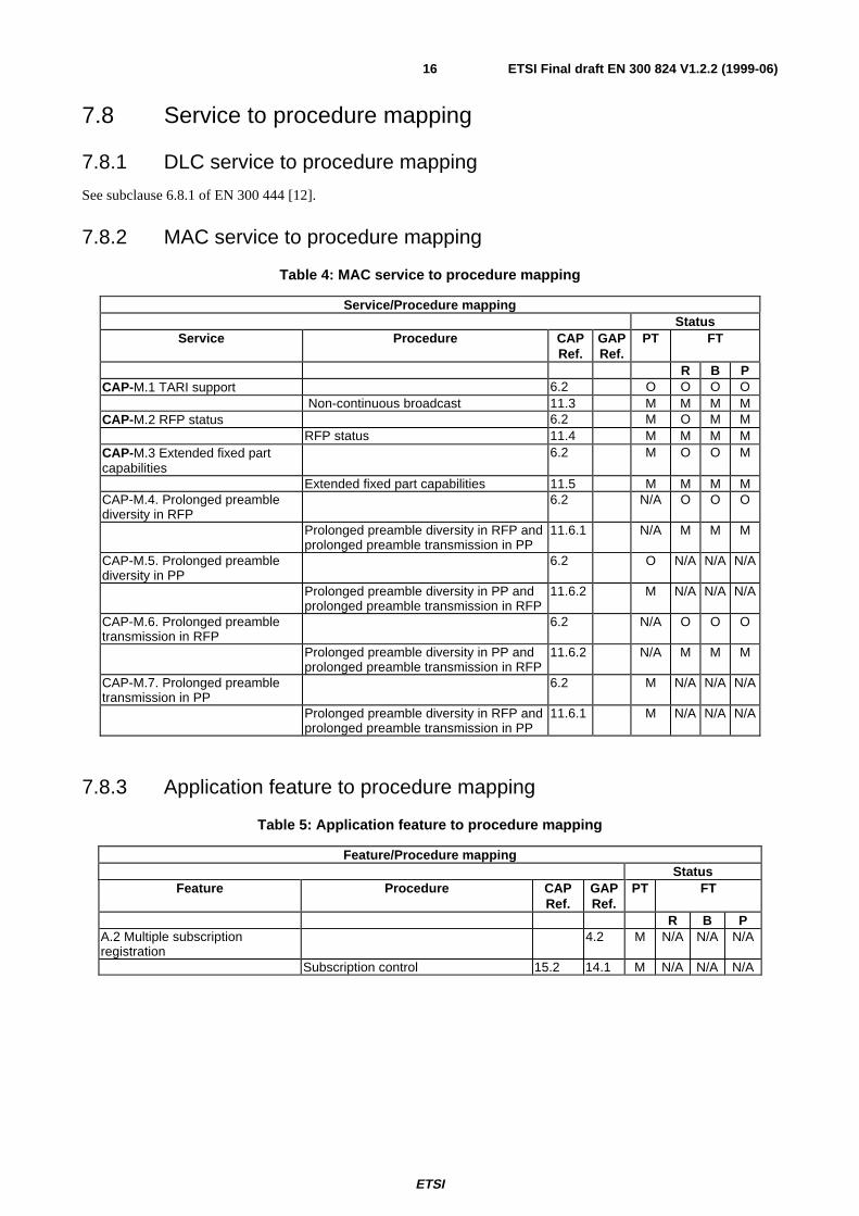
7.8.2 MAC service to procedure mapping
Table 4: MAC service to procedure mapping
Service/Procedure mappingStatus
Service Procedure CAPRef.
GAPRef.
PT FT
R B PCAP-M.1 TARI support 6.2 O O O O
Non-continuous broadcast 11.3 M M M MCAP-M.2 RFP status 6.2 M O M M
RFP status 11.4 M M M MCAP-M.3 Extended fixed partcapabilities
6.2 M O O M
Extended fixed part capabilities 11.5 M M M MCAP-M.4. Prolonged preamblediversity in RFP
6.2 N/A O O O
Prolonged preamble diversity in RFP andprolonged preamble transmission in PP
11.6.1 N/A M M M
CAP-M.5. Prolonged preamblediversity in PP
6.2 O N/A N/A N/A
Prolonged preamble diversity in PP andprolonged preamble transmission in RFP
11.6.2 M N/A N/A N/A
CAP-M.6. Prolonged preambletransmission in RFP
6.2 N/A O O O
Prolonged preamble diversity in PP andprolonged preamble transmission in RFP
11.6.2 N/A M M M
CAP-M.7. Prolonged preambletransmission in PP
6.2 M N/A N/A N/A
Prolonged preamble diversity in RFP andprolonged preamble transmission in PP
11.6.1 M N/A N/A N/A
7.8.3 Application feature to procedure mapping
Table 5: Application feature to procedure mapping
Feature/Procedure mappingStatus
Feature Procedure CAPRef.
GAPRef.
PT FT
R B PA.2 Multiple subscriptionregistration
4.2 M N/A N/A N/A
Subscription control 15.2 14.1 M N/A N/A N/A
ETSI
ETSI Final draft EN 300 824 V1.2.2 (1999-06)17
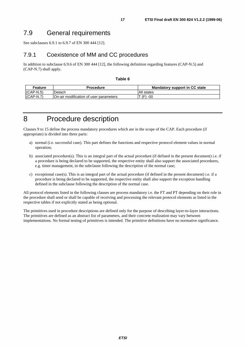
7.9 General requirementsSee subclauses 6.9.1 to 6.9.7 of EN 300 444 [12].
7.9.1 Coexistence of MM and CC procedures
In addition to subclause 6.9.6 of EN 300 444 [12], the following definition regarding features (CAP-N.5) and(CAP-N.7) shall apply.
Table 6
Feature Procedure Mandatory support in CC state(CAP-N.5) Detach All states(CAP-N.7) On-air modification of user parameters T (F) -00
8 Procedure descriptionClauses 9 to 15 define the process mandatory procedures which are in the scope of the CAP. Each procedure (ifappropriate) is divided into three parts:
a) normal (i.e. successful case). This part defines the functions and respective protocol element values in normaloperation;
b) associated procedure(s). This is an integral part of the actual procedure (if defined in the present document) i.e. ifa procedure is being declared to be supported, the respective entity shall also support the associated procedures,e.g. timer management, in the subclause following the description of the normal case;
c) exceptional case(s). This is an integral part of the actual procedure (if defined in the present document) i.e. if aprocedure is being declared to be supported, the respective entity shall also support the exception handlingdefined in the subclause following the description of the normal case.
All protocol elements listed in the following clauses are process mandatory i.e. the FT and PT depending on their role inthe procedure shall send or shall be capable of receiving and processing the relevant protocol elements as listed in therespective tables if not explicitly stated as being optional.
The primitives used in procedure descriptions are defined only for the purpose of describing layer-to-layer interactions.The primitives are defined as an abstract list of parameters, and their concrete realization may vary betweenimplementations. No formal testing of primitives is intended. The primitive definitions have no normative significance.
ETSI
ETSI Final draft EN 300 824 V1.2.2 (1999-06)18
9 NWK layer proceduresThis clause specifies the NWK layer procedures, messages and IEs required in the CAP.
This profile does not prevent any PT or FT transmitting or receiving and processing any other NWK layer message or IEnot specified in the profile. A PT or FT receiving an unsupported NWK layer message or IE which it does not recognizeshall ignore it, as specified in clause 17 of EN 300 175-5 [5].
9.1 External handover procedures
9.1.1 Handover candidate procedure
FP-1 shall only indicate handover candidates to which the PP has access using its active subscription.
Furthermore, the indicated candidates shall support External handover from the current FP. If the current FP supportsencryption, then the FP shall ensure that the indicated candidate FPs support encryption.
NOTE: The above implies that the PP does not need to analyse the Secondary Access Rights Identities (SARIs)and/or TARIs supported by FP-2 prior to attempting external handover. Likewise, the PP need not analysethe external handover nor the ciphering support bit broadcasted by FP-2 prior to attempting externalhandover.
9.1.1.1 Handover candidate indication
The procedure shall be performed as defined in subclause 15.7.1.2 of EN 300 175-5 [5]. The following text togetherwith the associated subclauses define the mandatory requirements with regard to the present document.
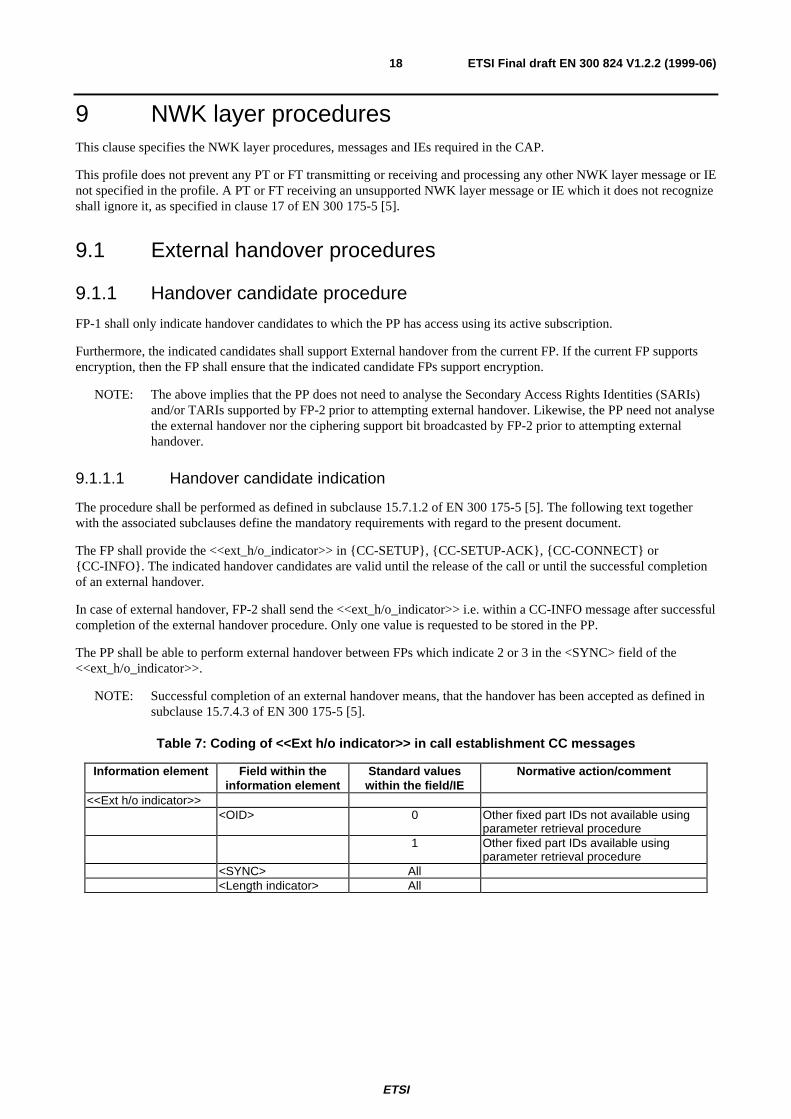
The FP shall provide the <<ext_h/o_indicator>> in {CC-SETUP}, {CC-SETUP-ACK}, {CC-CONNECT} or{CC-INFO}. The indicated handover candidates are valid until the release of the call or until the successful completionof an external handover.
In case of external handover, FP-2 shall send the <<ext_h/o_indicator>> i.e. within a CC-INFO message after successfulcompletion of the external handover procedure. Only one value is requested to be stored in the PP.
The PP shall be able to perform external handover between FPs which indicate 2 or 3 in the <SYNC> field of the<<ext_h/o_indicator>>.
NOTE: Successful completion of an external handover means, that the handover has been accepted as defined insubclause 15.7.4.3 of EN 300 175-5 [5].
Table 7: Coding of <<Ext h/o indicator>> in call establishment CC messages
Information element Field within theinformation element
Standard valueswithin the field/IE
Normative action/comment
<<Ext h/o indicator>><OID> 0 Other fixed part IDs not available using
parameter retrieval procedure1 Other fixed part IDs available using
parameter retrieval procedure<SYNC> All<Length indicator> All
ETSI
ETSI Final draft EN 300 824 V1.2.2 (1999-06)19
9.1.1.2 Handover candidate retrieval
The procedure shall be performed as defined in subclause 15.7.1.3 of EN 300 175-5 [5]. The following text togetherwith the associated subclauses define the mandatory requirements with regard to the present document.
The PP shall not invoke this procedure if the <<ext h/o indicator>> has not yet received or if the <<ext h/o indicator>>has been received with the OID value set to "0".
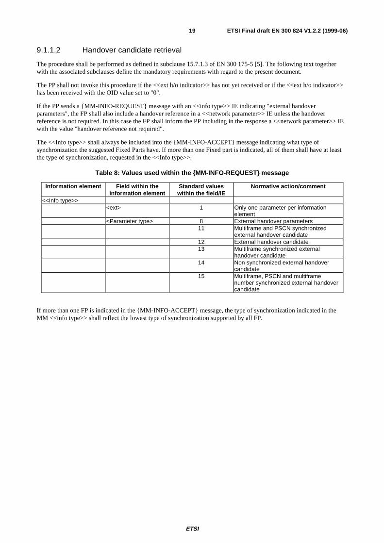
If the PP sends a {MM-INFO-REQUEST} message with an <<info type>> IE indicating "external handoverparameters", the FP shall also include a handover reference in a <<network parameter>> IE unless the handoverreference is not required. In this case the FP shall inform the PP including in the response a <<network parameter>> IEwith the value "handover reference not required".
The <<Info type>> shall always be included into the {MM-INFO-ACCEPT} message indicating what type ofsynchronization the suggested Fixed Parts have. If more than one Fixed part is indicated, all of them shall have at leastthe type of synchronization, requested in the <<Info type>>.
Table 8: Values used within the {MM-INFO-REQUEST} message
Information element Field within theinformation element
Standard valueswithin the field/IE
Normative action/comment
<<Info type>><ext> 1 Only one parameter per information
element<Parameter type> 8 External handover parameters
11 Multiframe and PSCN synchronizedexternal handover candidate
12 External handover candidate13 Multiframe synchronized external
handover candidate14 Non synchronized external handover
candidate15 Multiframe, PSCN and multiframe
number synchronized external handovercandidate
If more than one FP is indicated in the {MM-INFO-ACCEPT} message, the type of synchronization indicated in theMM <<info type>> shall reflect the lowest type of synchronization supported by all FP.
ETSI
ETSI Final draft EN 300 824 V1.2.2 (1999-06)20
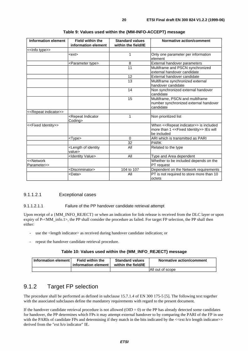
Table 9: Values used within the {MM-INFO-ACCEPT} message
Information element Field within theinformation element
Standard valueswithin the field/IE
Normative action/comment
<<Info type>><ext> 1 Only one parameter per information
element<Parameter type> 8 External handover parameters
11 Multiframe and PSCN synchronizedexternal handover candidate
12 External handover candidate13 Multiframe synchronized external
handover candidate14 Non synchronized external handover
candidate15 Multiframe, PSCN and multiframe
number synchronized external handovercandidate
<<Repeat indicator>><Repeat IndicatorCoding>
1 Non prioritized list
<<Fixed Identity>> When <<Repeat indicator>> is includedmore than 1 <<Fixed Identity>> IEs willbe included
<Type> 0 ARI which is transmitted as PARI32 PARK
<Length of identityvalue>
All Related to the type
<Identity Value> All Type and Area dependent<<NetworkParameter>>
Whether to be included depends on thePT request
<Discriminator> 104 to 107 Dependent on the Network requirements<Data> All PT is not required to store more than 10
octets
9.1.1.2.1 Exceptional cases
9.1.1.2.1.1 Failure of the PP handover candidate retrieval attempt
Upon receipt of a {MM_INFO_REJECT} or when an indication for link release is received from the DLC layer or uponexpiry of P-<MM_info.1>, the PP shall consider the procedure as failed. For target FP selection, the PP shall theneither:
- use the <length indicator> as received during handover candidate indication; or
- repeat the handover candidate retrieval procedure.
Table 10: Values used within the {MM_INFO_REJECT} message
Information element Field within theinformation element
Standard valueswithin the field/IE
Normative action/comment
All out of scope
9.1.2 Target FP selection
The procedure shall be performed as defined in subclause 15.7.1.4 of EN 300 175-5 [5]. The following text togetherwith the associated subclauses define the mandatory requirements with regard to the present document.
If the handover candidate retrieval procedure is not allowed (OID = 0) or the PP has already detected some candidatesfor handover, the PP determines which FPs it may attempt external handover to by comparing the PARI of the FP in usewith the PARIs of candidate FPs and determining if they match in the bits indicated by the <<ext h/o length indicator>>derived from the "ext h/o indicator" IE.
ETSI
ETSI Final draft EN 300 824 V1.2.2 (1999-06)21
9.1.3 Handover reference procedure
9.1.3.1 Handover reference indication
The procedure shall be performed as defined in subclause 15.7.2.2 of EN 300 175-5 [5].
9.1.3.2 Handover reference retrieval
The procedure shall be performed as defined in subclause 15.7.2.3 of EN 300 175-5 [5]. The following text togetherwith the associated subclauses define the mandatory requirements with regard to the present document.
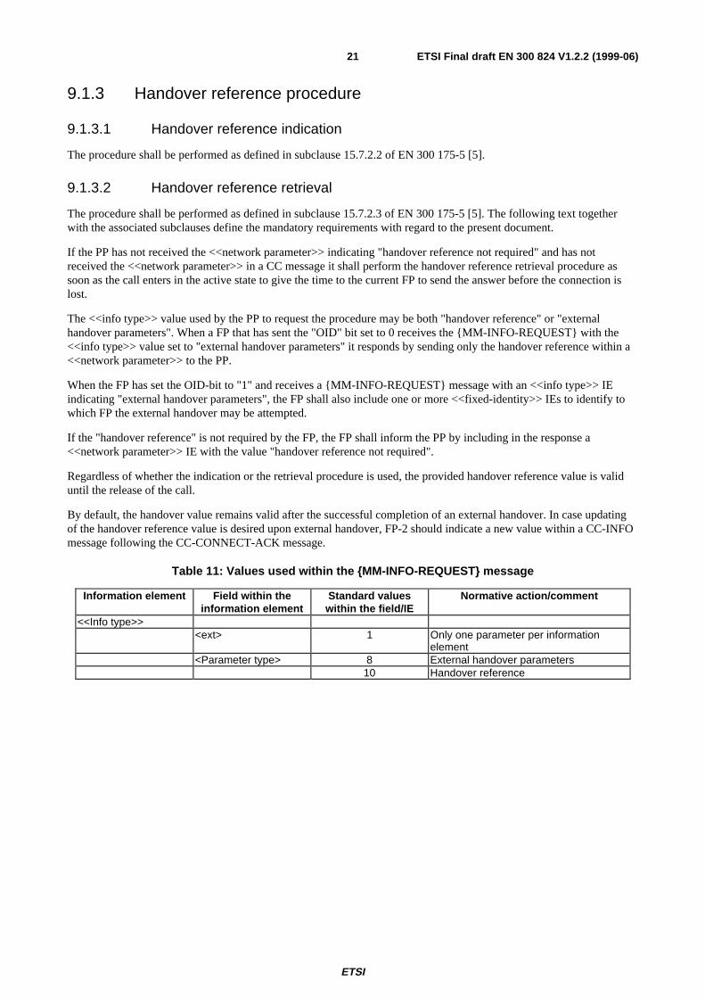
If the PP has not received the <<network parameter>> indicating "handover reference not required" and has notreceived the <<network parameter>> in a CC message it shall perform the handover reference retrieval procedure assoon as the call enters in the active state to give the time to the current FP to send the answer before the connection islost.
The <<info type>> value used by the PP to request the procedure may be both "handover reference" or "externalhandover parameters". When a FP that has sent the "OID" bit set to 0 receives the {MM-INFO-REQUEST} with the<<info type>> value set to "external handover parameters" it responds by sending only the handover reference within a<<network parameter>> to the PP.
When the FP has set the OID-bit to "1" and receives a {MM-INFO-REQUEST} message with an <<info type>> IEindicating "external handover parameters", the FP shall also include one or more <<fixed-identity>> IEs to identify towhich FP the external handover may be attempted.
If the "handover reference" is not required by the FP, the FP shall inform the PP by including in the response a<<network parameter>> IE with the value "handover reference not required".
Regardless of whether the indication or the retrieval procedure is used, the provided handover reference value is validuntil the release of the call.
By default, the handover value remains valid after the successful completion of an external handover. In case updatingof the handover reference value is desired upon external handover, FP-2 should indicate a new value within a CC-INFOmessage following the CC-CONNECT-ACK message.
Table 11: Values used within the {MM-INFO-REQUEST} message
Information element Field within theinformation element
Standard valueswithin the field/IE
Normative action/comment
<<Info type>><ext> 1 Only one parameter per information
element<Parameter type> 8 External handover parameters
10 Handover reference
ETSI
ETSI Final draft EN 300 824 V1.2.2 (1999-06)22
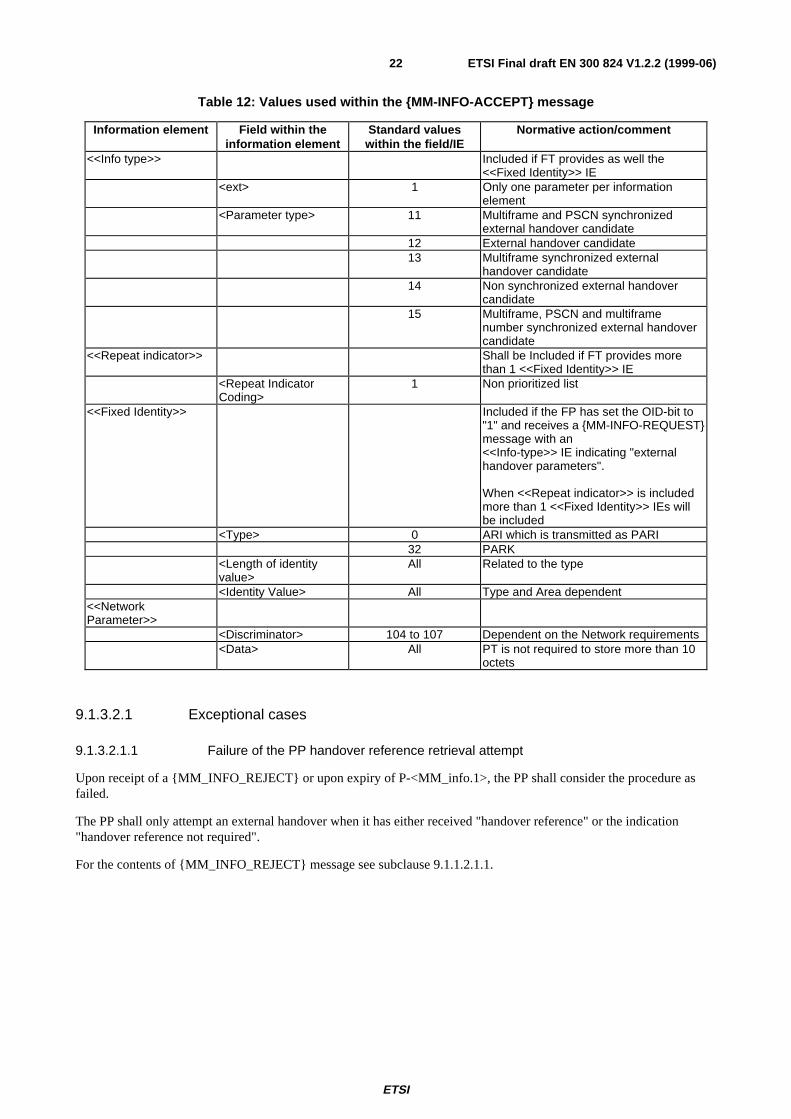
Table 12: Values used within the {MM-INFO-ACCEPT} message
Information element Field within theinformation element
Standard valueswithin the field/IE
Normative action/comment
<<Info type>> Included if FT provides as well the<<Fixed Identity>> IE
<ext> 1 Only one parameter per informationelement
<Parameter type> 11 Multiframe and PSCN synchronizedexternal handover candidate
12 External handover candidate13 Multiframe synchronized external
handover candidate14 Non synchronized external handover
candidate15 Multiframe, PSCN and multiframe
number synchronized external handovercandidate
<<Repeat indicator>> Shall be Included if FT provides morethan 1 <<Fixed Identity>> IE
<Repeat IndicatorCoding>
1 Non prioritized list
<<Fixed Identity>> Included if the FP has set the OID-bit to"1" and receives a {MM-INFO-REQUEST}message with an<<Info-type>> IE indicating "externalhandover parameters".
When <<Repeat indicator>> is includedmore than 1 <<Fixed Identity>> IEs willbe included
<Type> 0 ARI which is transmitted as PARI32 PARK
<Length of identityvalue>
All Related to the type
<Identity Value> All Type and Area dependent<<NetworkParameter>>
<Discriminator> 104 to 107 Dependent on the Network requirements<Data> All PT is not required to store more than 10
octets
9.1.3.2.1 Exceptional cases
9.1.3.2.1.1 Failure of the PP handover reference retrieval attempt
Upon receipt of a {MM_INFO_REJECT} or upon expiry of P-<MM_info.1>, the PP shall consider the procedure asfailed.
The PP shall only attempt an external handover when it has either received "handover reference" or the indication"handover reference not required".
For the contents of {MM_INFO_REJECT} message see subclause 9.1.1.2.1.1.
ETSI
ETSI Final draft EN 300 824 V1.2.2 (1999-06)23
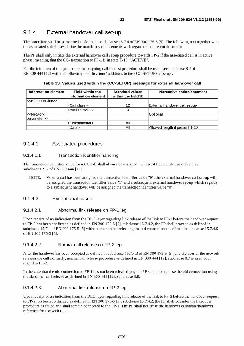
9.1.4 External handover call set-up
The procedure shall be performed as defined in subclause 15.7.4 of EN 300 175-5 [5]. The following text together withthe associated subclauses define the mandatory requirements with regard to the present document.
The PP shall only initiate the external handover call set-up procedure towards FP-2 if the associated call is in activephase; meaning that the CC- transaction to FP-1 is in state T-10: "ACTIVE".
For the initiation of this procedure the outgoing call request procedure shall be used, see subclause 8.2 ofEN 300 444 [12] with the following modifications/ additions to the {CC-SETUP} message.
Table 13: Values used within the {CC-SETUP} message for external handover call
Information element Field within theinformation element
Standard valueswithin the field/IE
Normative action/comment
<<Basic service>><Call class> 12 External handover call set-up<Basic service> 0
<<Networkparameter>>
Optional
<Discriminator> All<Data> All Allowed length if present 1-10
9.1.4.1 Associated procedures
9.1.4.1.1 Transaction identifier handling
The transaction identifier value for a CC call shall always be assigned the lowest free number as defined insubclause 6.9.2 of EN 300 444 [12].
NOTE: When a call has been assigned the transaction identifier value "0", the external handover call set-up willbe assigned the transaction identifier value "1" and a subsequent external handover set-up which regardsto a subsequent handover will be assigned the transaction identifier value "0".
9.1.4.2 Exceptional cases
9.1.4.2.1 Abnormal link release on FP-1 leg
Upon receipt of an indication from the DLC layer regarding link release of the link to FP-1 before the handover requestto FP-2 has been confirmed as defined in EN 300 175-5 [5], subclause 15.7.4.2, the PP shall proceed as defined insubclause 15.7.4 of EN 300 175-5 [5] without the need of releasing the old connection as defined in subclause 15.7.4.5of EN 300 175-5 [5].
9.1.4.2.2 Normal call release on FP-2 leg
After the handover has been accepted as defined in subclause 15.7.4.3 of EN 300 175-5 [5], and the user or the networkreleases the call normally, normal call release procedure as defined in EN 300 444 [12], subclause 8.7 is used withregard to FP-2.
In the case that the old connection to FP-1 has not been released yet, the PP shall also release the old connection usingthe abnormal call release as defined in EN 300 444 [12], subclause 8.8.
9.1.4.2.3 Abnormal link release on FP-2 leg
Upon receipt of an indication from the DLC layer regarding link release of the link to FP-2 before the handover requestto FP-2 has been confirmed as defined in EN 300 175-5 [5], subclause 15.7.4.2, the PP shall consider the handoverprocedure as failed and shall remain connected to the FP-1. The PP shall not erase the handover candidate/handoverreference for use with FP-1.
ETSI
ETSI Final draft EN 300 824 V1.2.2 (1999-06)24
In the case that the handover request to FP-2 has already been confirmed when receiving the link release indication, butthe PP has not yet released the old link to FP-1, the PP shall also either switch back to the old connection or release theold connection using the abnormal call release as defined in EN 300 444 [12], subclause 8.8.
9.1.5 Ciphering procedure
9.1.5.1 Ciphering procedure PT initiated
The procedure shall be performed as defined in the relevant parts of subclause 15.7.6 of EN 300 175-5 [5] andsubclause 8.34 of EN 300 444 [12].
The PP shall only initiate ciphering prior to the release of the old connection in case it supports ciphering on twoconnections.
9.1.5.2 Ciphering procedure FT initiated
The procedure shall be performed as defined in the relevant parts of subclause 15.7.6 of EN 300 175-5 [5] andsubclause 8.33 of EN 300 444 [12].
9.1.6 U-plane handling
The procedure shall be performed as defined in subclause 15.7.5 of EN 300 175-5 [5].
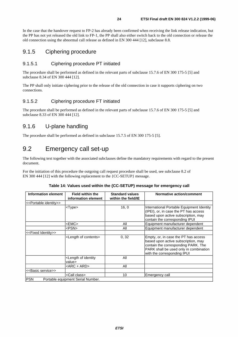
9.2 Emergency call set-upThe following text together with the associated subclauses define the mandatory requirements with regard to the presentdocument.
For the initiation of this procedure the outgoing call request procedure shall be used, see subclause 8.2 ofEN 300 444 [12] with the following replacement to the {CC-SETUP} message.
Table 14: Values used within the {CC-SETUP} message for emergency call
Information element Field within theinformation element
Standard valueswithin the field/IE
Normative action/comment
<<Portable identity>><Type> 16, 0 International Portable Equipment Identity
(IPEI), or, in case the PT has accessbased upon active subscription, maycontain the corresponding IPUI
<EMC> All Equipment manufacturer dependent<PSN> All Equipment manufacturer dependent
<<Fixed Identity>><Length of contents> 0, 32 Empty, or, in case the PT has access
based upon active subscription, maycontain the corresponding PARK. ThePARK shall be used only in combinationwith the corresponding IPUI
<Length of identityvalue>
All
<ARC + ARD> All<<Basic service>>
<Call class> 10 Emergency callPSN Portable equipment Serial Number.
ETSI
ETSI Final draft EN 300 824 V1.2.2 (1999-06)25
The FP shall accept the {CC-SETUP} message without checking the <<Fixed Identity>> and <<Portable identity>> IEand proceed with the network layer Outgoing call establishment procedures according to EN 300 444 [12] with thefollowing modification: If the FT-IWU sends MNCC_SETUP_ACK-req primitive (thereby forcing the FT to send a{CC-SETUP-ACK} message to the PT and to enter the “OVERLAP SENDING” state) it shall not wait for the PT tosubmit dialling information and it shall send as soon as possible (timer F<CC.01> shall not expire) aMNCC_CALL_PROC-reg, MNCC_ALERT-req or MNCC_CONNECT-req primitive thereby forcing the FT to changethe CC-state.
The FP shall not authenticate the PP and shall not request ciphering, moreover there shall be no authentication and nociphering in case access rights are not available. The portable part is not mandated to send dialling information duringemergency call.
If the emergency call set-up procedure leads into an abnormal call release according to EN 300 444 [12] subclause 8.8or if the FP rejects the outgoing call request according to subclause 8.2.2.3, the handset may search for another FPsupporting emergency calls.
9.3 DisplayThe procedure shall be performed as defined in subclauses 10.2 and D.2.2 of EN 300 175-5 [5]. The following texttogether with the associated subclauses define the mandatory requirements with regard to the present document.
An FT may send and a PT shall be able to process a <<Display>> information element even without prior transmissionof a <<Multi keypad>> information element.
A <<DISPLAY>> IE may be included in any CC messages in the FT → PT direction except in {CC-NOTIFY} and{IWU-INFO} see EN 300 175-5 [5], subclause 6.3.2.
Table 15: Values used within the <<DISPLAY>> IE in any message that include it
Information element Field within theinformation element
Standard valueswithin the field/IE
Normative action/comment
<<Multi display>><Display information> 0CH, 20H, 23H, 2AH,
30H - 7FHDECT standard characters = standardIA5 characters. For the actual supportedvalues see <<Terminal capability>> I.E.
02H, 03H, 08H - 0FH,19H - 7FH
DECT control characters. For the actualsupported values see <<Terminalcapability>> I.E.
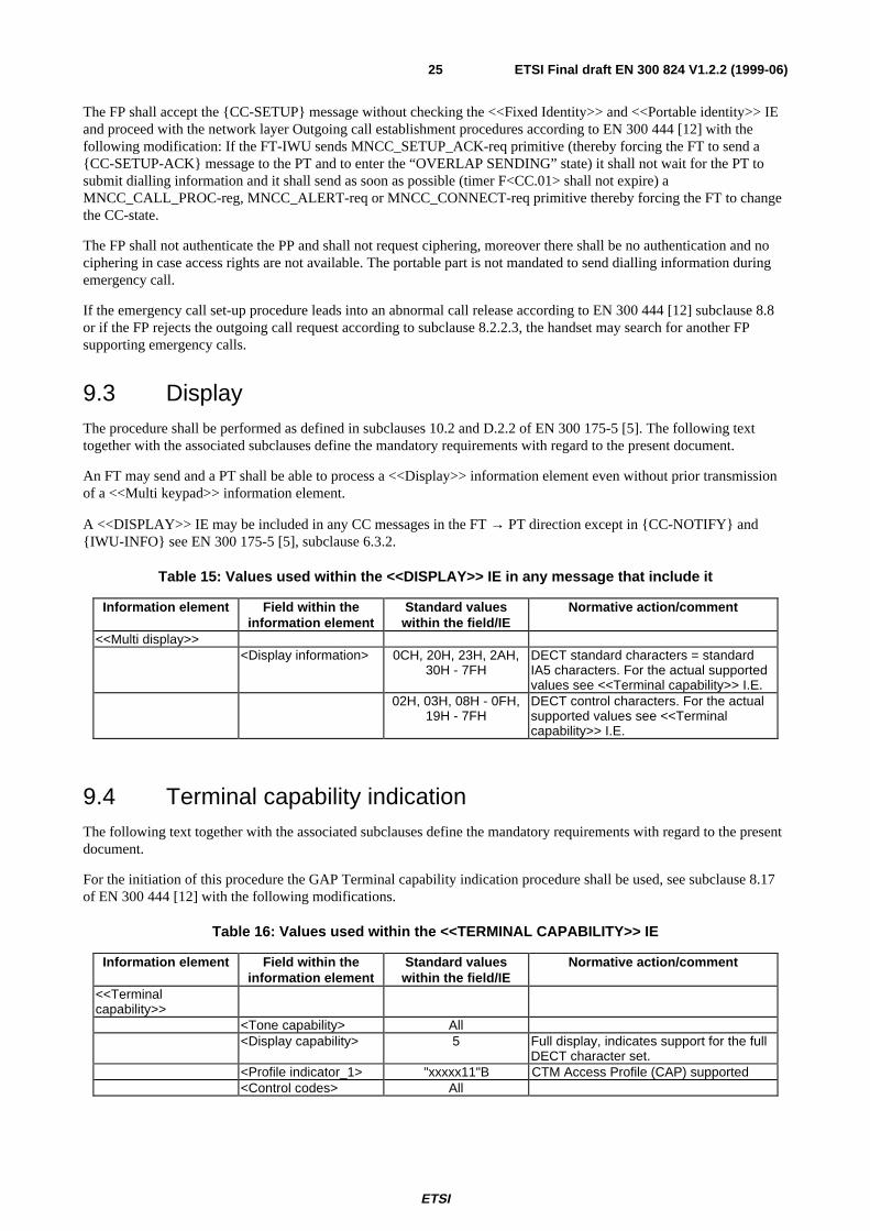
9.4 Terminal capability indicationThe following text together with the associated subclauses define the mandatory requirements with regard to the presentdocument.
For the initiation of this procedure the GAP Terminal capability indication procedure shall be used, see subclause 8.17of EN 300 444 [12] with the following modifications.
Table 16: Values used within the <<TERMINAL CAPABILITY>> IE
Information element Field within theinformation element
Standard valueswithin the field/IE
Normative action/comment
<<Terminalcapability>>
<Tone capability> All<Display capability> 5 Full display, indicates support for the full
DECT character set.<Profile indicator_1> "xxxxx11"B CTM Access Profile (CAP) supported<Control codes> All
ETSI
ETSI Final draft EN 300 824 V1.2.2 (1999-06)26
9.5 DetachThe procedure shall be performed as defined in subclause 13.4.2 of EN 300 175-5 [5]. The following text defines themandatory requirements with regard to the present document.
PT FT
D E T A C H
Figure 1: Detach
Table 17: Values used within the {DETACH} message
Information element Field within theinformation element
Standard valueswithin the field/IE
Normative action/comment
<<Portable-identity>><Type> 0 IPUI<PUT> All<PUN> All
PUN: Portable User NumberPUT: Portable User Type
9.6 Enhanced location registrationThe procedure relates to the feature Periodic location registration (CAP-N.6) and it shall be performed as defined insubclause 13.4.1 of EN 300 175-5 [5] and 6.3.1 of EN 300 175-6 [6]. The following text together with the associatedsubclauses define the mandatory requirements with regard to the present document.
To allow periodic location registration, the PT shall evaluate the <<Duration>> IE in {LOCATE-ACCEPT} messages.The PT shall not attempt another location registration before the expiry of the timers defined in <Lock limits> and<Time limits> fields, unless a condition for the initiation of a new location registration (as defined in 14.2) may apply.
For the initiation of this procedure the location registration procedure shall be used, see subclause 8.28 ofEN 300 444 [12] with the following addition to the {LOCATE-ACCEPT} message and subsequent modifications.
Table 18: Values used within {LOCATE-ACCEPT} message for enhanced location registration
Information element Field within theinformation element
Standard valueswithin the field/IE
Normative action/comment
<<Duration>><Lock limits> 111 (binary) No limits
101 (binary) Temporary user limit 2110 (binary) Temporary user limit 1
<Time limits> 1 Defined time limit 12 Defined time limit 2
15 Infinite<Time duration> All
ETSI
ETSI Final draft EN 300 824 V1.2.2 (1999-06)27
9.6.1 Exceptional case(s)
9.6.1.1 Failure of location registration procedure
Upon expire of <MM_locate.1> or indication for link released is received from the DLC layer, PT shall consider theprocedure as failed. The PP shall maintain the existing LAL value. PT shall not re-transmit the {LOCATE-REQUEST}message. and shall not restart the timer <MM_locate.1> as part of the same procedure.
To avoid unfinished location registration due to exceptional cases like link failure or bad radio quality the P-IWU shalleither repeat an unresponded location registration procedure until it receives a {LOCATE-ACCEPT} or {LOCATE-REJECT} message or attempt location registration in a different location area.
To enable the FT to control the duration until another location registration attempt, the PT shall evaluate the<<Duration>> if received in a {LOCATE-REJECT} message. The PT shall not attempt another location registrationbefore the expiry of the timers defined in <Lock limits> and <Time limits> fields, unless a condition for the initiation ofa new location registration (as defined in 14.2) may apply.
Table 19: Values used within {LOCATE-REJECT} message for enhanced location registration
Information element Field within theinformation element
Standard valueswithin the field/IE
Normative action/comment
<<Duration>><Lock limits> 111 (binary) No limits
101 (binary) Temporary user limit 1110 (binary) Temporary user limit 2
<Time limits> 1 Defined time limit 12 Defined time limit 2
15 Infinite<Time duration> All
If the PT receives no response to {LOCATE-REQUEST}, it shall wait at least N700 seconds but no longer thanN700 + N800 seconds, starting upon expiry of <MM_locate.1>, before re-attempting location registration in the samelocation area. If the PT is not able to establish or fails to maintain the link during the location registration procedure itshall wait at least N700 seconds but no longer than N700 + N800 seconds, starting upon receipt of DL_RELEASE-ind,before re-attempting location registration in the same location area.
9.7 Message waiting indicationThe procedure relates to the feature (CAP-N.4, see subclause 5.1) Message Waiting Indication and shall be performedas defined in subclause 10.4.2.3 of EN 300 175-5 [5]. Basic services shall be coded as defined in EN 300 196-1 [17].
The following text defines the mandatory requirements with regard to EN 300 175-5 [5], EN 300 196-1 [17] andEN 300 745-1 [15].
Only the MWIIndicate operation definition shall apply to the present document. The procedure defined supportsdifferent modes of invocation, as defined in EN 300 745-1 [15].
FT shall use an already established link for the purpose of transmitting the facility containing the message waitingindication to the PT. If link is not available, the FT shall initiate indirect link establishment. Direct FT initiated linkestablishment is out of the scope of the present document. All MWIIndicate arguments defined in EN 300 745-1 [15]may be used. However, the following minimum requirements apply for the FP and the PP:
- the FP shall send the "basicService" argument to indicate the kind of message, "basicService" elements shall becoded as defined in EN 300 196-1 [17]. The PP shall support a separate MWI status for each of the followingbasic service values:
1) voice messages shall be indicated using the "speech (1)" coding;
2) text messages shall be indicated using the "teletex (33)" coding;
3) other and unknown messages shall be indicated using the "allServices (0)" coding.
ETSI
ETSI Final draft EN 300 824 V1.2.2 (1999-06)28
- all other codings are optional to understand for the PP;
- the FP may send the "controllingUserNumber" argument to indicate the party number of the correspondingmessage server. If the PP supports this, then the PP shall store the number and may use this to call the messageserver and the minimum PP storing requirement for this number shall be 10 octets (20 digits);
- the PP shall support the "numberOfMessages" argument which may be used to indicate how many messages forthe specific Basic Service are waiting. The PP shall be capable to handle values up to 127.
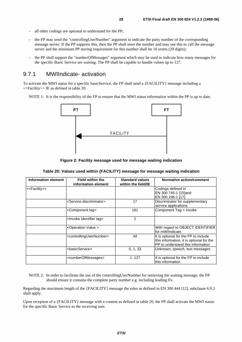
9.7.1 MWIIndicate- activation
To activate the MWI status for a specific basicService, the FP shall send a {FACILITY} message including a<<Facility>> IE as defined in table 20.
NOTE 1: It is the responsibility of the FP to ensure that the MWI status information within the PP is up to date.
PT FT
FACILITY
Figure 2: Facility message used for message waiting indication
Table 20: Values used within {FACILITY} message for message waiting indication
Information element Field within theinformation element
Standard valueswithin the field/IE
Normative action/comment
<<Facility>> Codings defined inEN 300 745-1 [15]andEN 300 196-1 [17]
<Service discriminator> 17 Discriminator for supplementaryservice applications
<Component tag> 161 Component Tag = Invoke
<Invoke Identifier tag> 2
<Operation Value > With regard to OBJECT IDENTIFIERfor mWIIndicate
<controllingUserNumber> All It is optional for the FP to includethis information, it is optional for thePP to understand this information
<basicService> 0, 1, 33 Unknown, speech, text messages
<numberOfMessages> 1..127 It is optional for the FP to includethis information
NOTE 2: In order to facilitate the use of the controllingUserNumber for retrieving the waiting message, the FPshould ensure it contains the complete party number e.g. including leading 0's.
Regarding the maximum length of the {FACILITY} message the rules as defined in EN 300 444 [12], subclause 6.9.3shall apply.
Upon reception of a {FACILITY} message with a content as defined in table 20, the PP shall activate the MWI statusfor the specific Basic Service to the receiving user.
ETSI
ETSI Final draft EN 300 824 V1.2.2 (1999-06)29
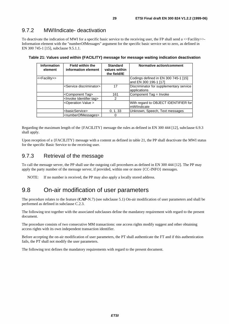
9.7.2 MWIIndicate- deactivation
To deactivate the indication of MWI for a specific basic service to the receiving user, the FP shall send a <<Facility>>-Information element with the "numberOfMessages" argument for the specific basic service set to zero, as defined inEN 300 745-1 [15], subclause 9.5.1.1.
Table 21: Values used within {FACILITY} message for message waiting indication deactivation
Informationelement
Field within theinformation element
Standardvalues within
the field/IE
Normative action/comment
<<Facility>> Codings defined in EN 300 745-1 [15]and EN 300 196-1 [17]
<Service discriminator> 17 Discriminator for supplementary serviceapplications
<Component Tag> 161 Component Tag = Invoke<Invoke Identifier tag> 2<Operation Value > With regard to OBJECT IDENTIFIER for
mWIIndicate<basicService> 0, 1, 33 Unknown, Speech, Text messages<numberOfMessages> 0
Regarding the maximum length of the {FACILITY} message the rules as defined in EN 300 444 [12], subclause 6.9.3shall apply.
Upon reception of a {FACILITY} message with a content as defined in table 21, the PP shall deactivate the MWI statusfor the specific Basic Service to the receiving user.
9.7.3 Retrieval of the message
To call the message server, the PP shall use the outgoing call procedures as defined in EN 300 444 [12]. The PP mayapply the party number of the message server, if provided, within one or more {CC-INFO} messages.
NOTE: If no number is received, the PP may also apply a locally stored address.
9.8 On-air modification of user parametersThe procedure relates to the feature (CAP-N.7) (see subclause 5.1) On-air modification of user parameters and shall beperformed as defined in subclause C.2.3.
The following text together with the associated subclauses define the mandatory requirement with regard to the presentdocument.
The procedure consists of two consecutive MM transactions: one access rights modify suggest and other obtainingaccess rights with its own independent transaction identifier.
Before accepting the on-air modification of user parameters, the PT shall authenticate the FT and if this authenticationfails, the PT shall not modify the user parameters.
The following text defines the mandatory requirements with regard to the present document.
ETSI
ETSI Final draft EN 300 824 V1.2.2 (1999-06)30
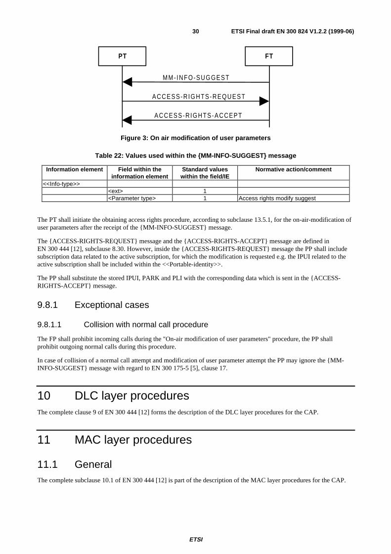
PT FT
MM- INFO-SUGGEST
ACCESS-R IGHTS-REQUEST
ACCESS-R IGHTS-ACCEPT
Figure 3: On air modification of user parameters
Table 22: Values used within the {MM-INFO-SUGGEST} message
Information element Field within theinformation element
Standard valueswithin the field/IE
Normative action/comment
<<Info-type>><ext> 1<Parameter type> 1 Access rights modify suggest
The PT shall initiate the obtaining access rights procedure, according to subclause 13.5.1, for the on-air-modification ofuser parameters after the receipt of the {MM-INFO-SUGGEST} message.
The {ACCESS-RIGHTS-REQUEST} message and the {ACCESS-RIGHTS-ACCEPT} message are defined inEN 300 444 [12], subclause 8.30. However, inside the {ACCESS-RIGHTS-REQUEST} message the PP shall includesubscription data related to the active subscription, for which the modification is requested e.g. the IPUI related to theactive subscription shall be included within the <<Portable-identity>>.
The PP shall substitute the stored IPUI, PARK and PLI with the corresponding data which is sent in the {ACCESS-RIGHTS-ACCEPT} message.
9.8.1 Exceptional cases
9.8.1.1 Collision with normal call procedure
The FP shall prohibit incoming calls during the "On-air modification of user parameters" procedure, the PP shallprohibit outgoing normal calls during this procedure.
In case of collision of a normal call attempt and modification of user parameter attempt the PP may ignore the {MM-INFO-SUGGEST} message with regard to EN 300 175-5 [5], clause 17.
10 DLC layer proceduresThe complete clause 9 of EN 300 444 [12] forms the description of the DLC layer procedures for the CAP.
11 MAC layer procedures
11.1 GeneralThe complete subclause 10.1 of EN 300 444 [12] is part of the description of the MAC layer procedures for the CAP.
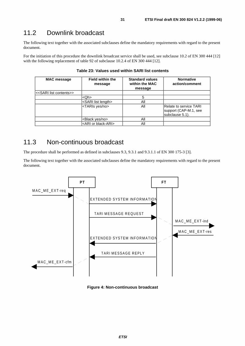
ETSI
ETSI Final draft EN 300 824 V1.2.2 (1999-06)31
11.2 Downlink broadcastThe following text together with the associated subclauses define the mandatory requirements with regard to the presentdocument.
For the initiation of this procedure the downlink broadcast service shall be used, see subclause 10.2 of EN 300 444 [12]with the following replacement of table 92 of subclause 10.2.4 of EN 300 444 [12].
Table 23: Values used within SARI list contents
MAC message Field within themessage
Standard valueswithin the MAC
message
Normativeaction/comment
<<SARI list contents>><Qh> 5<SARI list length> All<TARIs yes/no> All Relate to service TARI
support (CAP-M.1, seesubclause 5.1).
<Black yes/no> All<ARI or black-ARI> All
11.3 Non-continuous broadcastThe procedure shall be performed as defined in subclauses 9.3, 9.3.1 and 9.3.1.1 of EN 300 175-3 [3].
The following text together with the associated subclauses define the mandatory requirements with regard to the presentdocument.
PT FT
T A R I M E S S A G E R E Q U E S T
T A R I M E S S A G E R E P LY
E X TE N D E D S YS T E M IN F O R M A T IO N
E X TE N D E D S YS T E M IN F O R M A T IO N
M A C _M E _E X T-req
M A C _M E _E X T -cfm
M A C _M E _E X T -ind
M A C _M E _E X T-res
Figure 4: Non-continuous broadcast
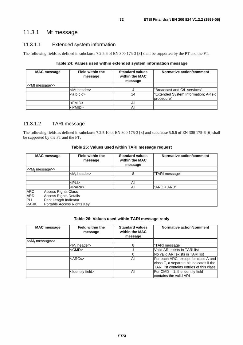
ETSI
ETSI Final draft EN 300 824 V1.2.2 (1999-06)32
11.3.1 Mt message
11.3.1.1 Extended system information
The following fields as defined in subclause 7.2.5.6 of EN 300 175-3 [3] shall be supported by the PT and the FT.
Table 24: Values used within extended system information message
MAC message Field within themessage
Standard valueswithin the MAC
message
Normative action/comment
<<Mt message>><Mt header> 4 "Broadcast and C/L services"<a b c d> 14 "Extended System Information; A-field
procedure"<FMID> All<PMID> All
11.3.1.2 TARI message
The following fields as defined in subclause 7.2.5.10 of EN 300 175-3 [3] and subclause 5.6.6 of EN 300 175-6 [6] shallbe supported by the PT and the FT.
Table 25: Values used within TARI message request
MAC message Field within themessage
Standard valueswithin the MAC
message
Normative action/comment
<<Mt message>><Mt header> 8 "TARI message"
<PLI> All<PARK> All "ARC + ARD"
ARC Access Rights ClassARD Access Rights DetailsPLI Park Length IndicatorPARK Portable Access Rights Key
Table 26: Values used within TARI message reply
MAC message Field within themessage
Standard valueswithin the MAC
message
Normative action/comment
<<Mt message>><Mt header> 8 "TARI message"<CMD> 1 Valid ARI exists in TARI list
0 No valid ARI exists in TARI list<ARCs> All For each ARC, except for class A and
class E, a separate bit indicates if theTARI list contains entries of this class
<Identity field> All For CMD = 1, the identity fieldcontains the valid ARI
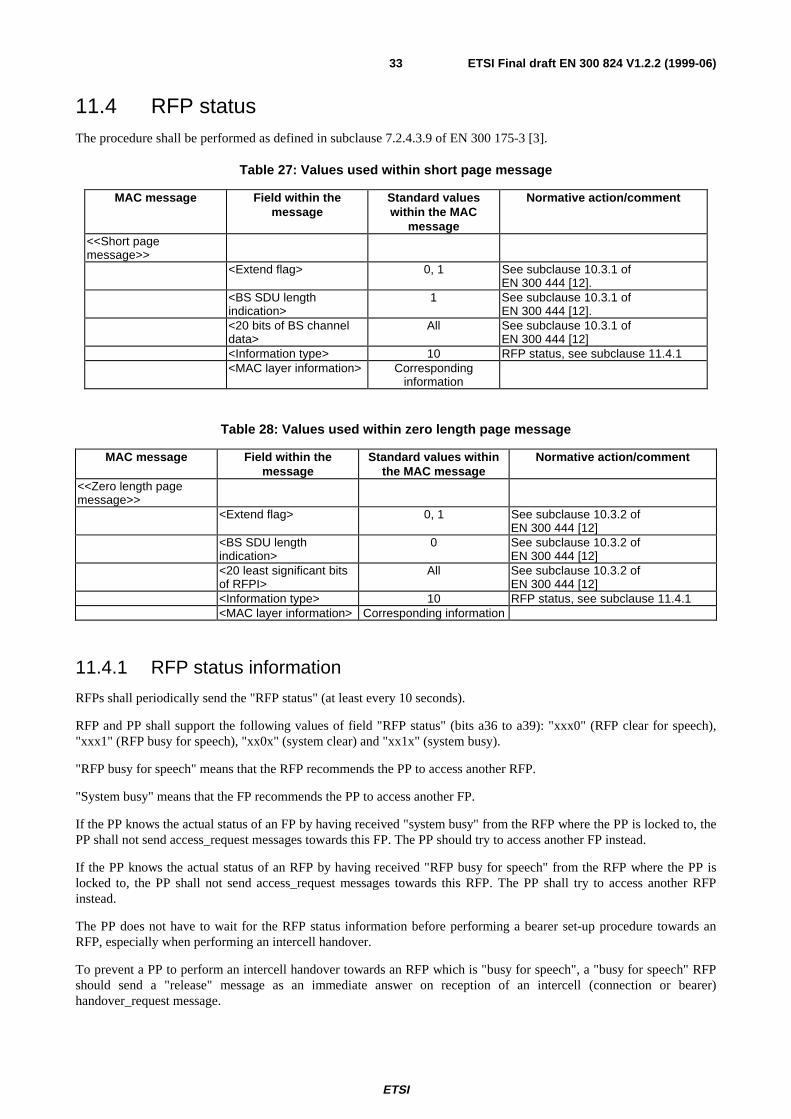
ETSI
ETSI Final draft EN 300 824 V1.2.2 (1999-06)33
11.4 RFP statusThe procedure shall be performed as defined in subclause 7.2.4.3.9 of EN 300 175-3 [3].
Table 27: Values used within short page message
MAC message Field within themessage
Standard valueswithin the MAC
message
Normative action/comment
<<Short pagemessage>>
<Extend flag> 0, 1 See subclause 10.3.1 ofEN 300 444 [12].
<BS SDU lengthindication>
1 See subclause 10.3.1 ofEN 300 444 [12].
<20 bits of BS channeldata>
All See subclause 10.3.1 ofEN 300 444 [12]
<Information type> 10 RFP status, see subclause 11.4.1<MAC layer information> Corresponding
information
Table 28: Values used within zero length page message
MAC message Field within themessage
Standard values withinthe MAC message
Normative action/comment
<<Zero length pagemessage>>
<Extend flag> 0, 1 See subclause 10.3.2 ofEN 300 444 [12]
<BS SDU lengthindication>
0 See subclause 10.3.2 ofEN 300 444 [12]
<20 least significant bitsof RFPI>
All See subclause 10.3.2 ofEN 300 444 [12]
<Information type> 10 RFP status, see subclause 11.4.1<MAC layer information> Corresponding information
11.4.1 RFP status information
RFPs shall periodically send the "RFP status" (at least every 10 seconds).
RFP and PP shall support the following values of field "RFP status" (bits a36 to a39): "xxx0" (RFP clear for speech),"xxx1" (RFP busy for speech), "xx0x" (system clear) and "xx1x" (system busy).
"RFP busy for speech" means that the RFP recommends the PP to access another RFP.
"System busy" means that the FP recommends the PP to access another FP.
If the PP knows the actual status of an FP by having received "system busy" from the RFP where the PP is locked to, thePP shall not send access_request messages towards this FP. The PP should try to access another FP instead.
If the PP knows the actual status of an RFP by having received "RFP busy for speech" from the RFP where the PP islocked to, the PP shall not send access_request messages towards this RFP. The PP shall try to access another RFPinstead.
The PP does not have to wait for the RFP status information before performing a bearer set-up procedure towards anRFP, especially when performing an intercell handover.
To prevent a PP to perform an intercell handover towards an RFP which is "busy for speech", a "busy for speech" RFPshould send a "release" message as an immediate answer on reception of an intercell (connection or bearer)handover_request message.
ETSI
ETSI Final draft EN 300 824 V1.2.2 (1999-06)34
Immediate means in the frame after reception of the intercell handover_request message. Therefore this immediate"release" message indicates the "RFP busy for speech" state of an RFP and a PP can try a next alternative RFP ifpossible.
11.5 Extended fixed part capabilitiesThe procedure shall be performed as defined in subclauses 7.2.3.5 and 7.2.3.1 of EN 300 175-3 [3].
Table 29: Values used within extended fixed part capabilities message
MAC message Field within themessage
Standard valueswithin the MAC
message
Normative action/comment
<<Extended FPcapabilities>>
<Qh> 4
For the setting of the extended higher layer information bits see subclause 14.8.
11.6 Prolonged preamble
11.6.1 Procedure for prolonged preamble diversity in RFP and prolongedpreamble transmission in PP
The procedure shall be performed as defined in subclause 7.2.5.5.1.1 of EN 300 175-3 [3].
At the reception of the quality control prolonged preamble request message, the PP shall confirm at the next allowedframe by sending the quality control prolonged preamble confirm message.
All PP transmissions until the quality control prolonged preamble confirm message (included) shall not contain theprolonged preamble.
The RFP shall not request the PP to send prolonged preamble if it broadcasts a standard synchronization field option inthe extended fixed part capabilities message (bits a18 to a19, subclause 7.2.3.5.2.2 of EN 300 175-3 [3]).
11.6.2 Procedure for prolonged preamble diversity in PP and prolongedpreamble transmission in RFP
The procedure shall be performed as defined in subclause 7.2.5.5.1.2 of EN 300 175-3 [3].
At the reception of the quality control prolonged preamble request message, the RFP shall confirm at the next allowedframe by sending the quality control prolonged preamble confirm message.
All RFP transmissions until the quality control prolonged preamble confirm message (included) shall not contain theprolonged preamble.
The PP shall not request the RFP to send prolonged preamble if the RFP broadcasts a standard synchronization fieldoption in the extended fixed part capabilities message (bits a18 to a19, subclause 7.2.3.5.2.2 of EN 300 175-3 [3]).
12 Physical layer requirements
12.1 GeneralThe complete clause 11 of EN 300 444 [12] is part of the description of the PHL procedures for the CAP with thefollowing modifications.
ETSI
ETSI Final draft EN 300 824 V1.2.2 (1999-06)35
12.2 External handoverA PP supporting external handover shall be capable of performing external handover between two RFPs belonging todifferent FPs which are multiframe synchronized with a reference timer difference up to P100 µsec.
A PP may be capable of supporting external handover between less accurately synchronized or not synchronized RFPs.
12.3 Prolonged PreambleThe measurement for traffic channel selections should include the prolonged preamble when the prolonged preamble issupported by FT and PT. (EN 300 175-3 [3], subclause 7.2.3.5.2.2).
13 Requirements regarding the speech transmission
13.1 General
The applicable requirements specified in EN 300 175-8 [8] and TBR 10 [11] shall be applied.
13.2 Reference to GAPThe complete clause 12 of EN 300 444 [12] is part of the description of the requirements regarding the speechtransmission for the CAP.
14 Management procedures
14.1 GeneralThe complete clause 13 of EN 300 444 [12] is part of the description of the management procedures for the CAP withthe following modifications.
14.2 Location registration initiationThe initiation of the location registration procedure (PT initiated) is dependent on the value of call attribute a38
broadcast by the FT, i.e. if set to "1", the PT initiates the location registration procedure in the following cases:
- immediately after a successful access rights procedure;
- upon change of location area; latest immediately after entering the CC null state (T-00);
- upon power-up and after the first lock to a system which the PT has access rights to;
- upon expire of the time limit indicated in the <<DURATION>> IE received during the last successful locationregistration on the same system or received inside a {LOCATE-REJECT} message as defined insubclause 9.6.1.1;
- after losing synchronization (leaving the locked state) for the time defined by the <Lock limits> parameterindicated in the <<DURATION>> IE (see subclause 9.6) received during the last successful location registrationon the same system;
- upon lock to a system after change of the active IPUI/PARK pair (i.e. change of actual subscription).
If the <<DURATION>> IE cannot be understood, the PT shall ignore the <<DURATION>> IE.
ETSI
ETSI Final draft EN 300 824 V1.2.2 (1999-06)36
Location registration shall be performed regardless if the system has been accessed via a PARI, SARI or TARI.
If call attribute a38 set to "0", the PT does not initiate the location registration procedure except upon receipt of "Locatesuggest" in the parameter retrieval procedure initiated by the FT.
The FT may initiate and the PT may receive incoming calls without a location registration procedure. The initiation ofthe location registration procedure as defined in subclause 8.28 of EN 300 444 [12] is always mandatory in the PTexcept when bit a38 in the broadcast attributes, see subclause 13.6 table 102 of EN 300 444 [12], is set to 0.
14.3 Assigned individual Temporary Portable User Identity(TPUI) management
Only one individual assigned TPUI shall be stored per subscription i.e. any new assignments of an individual assignedTPUI overwrites an existing individual assigned TPUI.
The PT shall always delete the old individual assigned TPUI immediately when entering a new location area prior theinitiation of location registration procedure. The PT shall always delete the old individual assigned TPUI immediatelywhen entering a new location area even if the location registration is not being performed i.e. the broadcast attribute a38
is set to value "0", see subclause 13.6 table 102 of EN 300 444 [12].
Upon detach TPUI shall be deleted in PT.
The default TPUI shall be derived from the allocated International Portable User Identity (IPUI). If no IPUI has beenallocated, the TPUI shall be derived from IPUI N i.e. the IPEI.
The LCE-PAGE-REJECT message shall not be used to delete an assigned TPUI.
NOTE: To avoid ambiguities of assigned TPUIs/Portable part MAC Identities (PMIDs), assigned TPUIs shouldbe unique within the entire FP rather then within location areas. See also note 2 in subclause 6.3.1 ofEN 300 175-6 [6].
14.4 DetachDetach shall be performed immediately upon power-down of PT if the PT is still in range of the active subscription.
Detach shall be performed to an active subscription before change of subscription if the PT is still in the range of thepreviously active subscription.
If, in this case, location registration is supported on the new subscription, detach shall be performed to the activesubscription prior to location registration to the new subscription.
The PT is not required to send the {DETACH} message to residential FTs.
In case of detach, MM may indicate that the normal link release procedures shall be used.
14.5 External handoverThe PT shall not initiate location registration during external handover.
The PT shall not perform an external handover within N500 seconds after the last successfully performed externalhandover.
After N501 consecutive unsuccessful attempts, the PP shall wait N500 seconds before initiating a new external handoverattempt.
Regarding handover retrieval, the minimum PP storage requirement is 3 handover candidates.
ETSI
ETSI Final draft EN 300 824 V1.2.2 (1999-06)37
14.6 Emergency call managementEmergency call is initiated by a special manual interworking at the MMI of a DECT PP. This may be the dialling of"112", pressing of a special "emergency call button", or selecting a menu-item.
After recognition of this manual interworking the PP may decide whether:
a) to initiate the emergency call procedure; or
b) to initiate a normal outgoing call (according to EN 300 444 [12]) and dial automatically a (preconfigured)emergency call number.
Case b) is allowed only, when the PP is locked to a DECT FP where it has access-rights to.
NOTE 1: In Case a) if the PP is not synchronized to a FP which supports emergency calls, the PP should start tosearch for an FP which supports emergency calls. The PP recognizes this by reading the extended higherlayer capabilities of the FP. Because it is most likely that a public DECT FP supports emergency calls, thePP should try first to synchronize to a public FP. The PP identifies a system being "public" using theidentity ARC which is broadcast more often than the "emergency call supported" message by the RFPs. Ifthere is no public FP supporting emergency calls available, the handset should try to search also forprivate FPs supporting emergency calls.
If a PP is not in range of a FP where it has access-rights to, the PP is allowed to lock to every FP in range whichsupports emergency calls even when no emergency call is initiated. This will shorten the time for setting up emergencycalls and makes it possible to indicate the availability of the emergency call to the user. If the PP is locked to a FP, towhich it does not have access-rights to, the PP shall not initiate any other procedure than emergency call set-up towardsthis FP.
NOTE 2: When locked to an FP providing emergency call access only, the PP should not completely stop searchingfor FP's matching one of the active subscription.
14.7 PMID managementIf the PP has a valid assigned individual TPUI, the PMID shall be this TPUI.
If the PP has not a valid assigned individual TPUI, the PMID shall be the arbitrary PMID. It may be derived from theIPUI used for the MAC connection set-up.
If a link has to be established for an external handover into a new location area, the arbitrary PMID shall be used for thislink establishment.
A PP attempting an emergency call shall use the emergency call TPUI as defined in EN 300 175-6 [6] subclause 6.3.1 asPMID value.
Within a link establishment procedure, the assigned PMID is recalculated for every connection set-up attempt (duringthe connection set-up procedure the assigned PMID shall not change); the arbitrary PMID is recalculated for every newbearer set-up attempt.
The PT shall not update its PMID until the current DLC link is released even if a connection or bearer handover hastaken place or the individual assigned TPUI has changed, e.g. due to change of the LA.
14.8 Broadcast attributes managementRFPs belonging to the same location area shall broadcast the same values of higher layer attributes at any given time(see annex F in EN 300 175-5 [5]).
The CAP PP shall be capable to read and interpret at least the following broadcast attributes codings during lockingprocedure. In the locked state the PP may assume them as static.
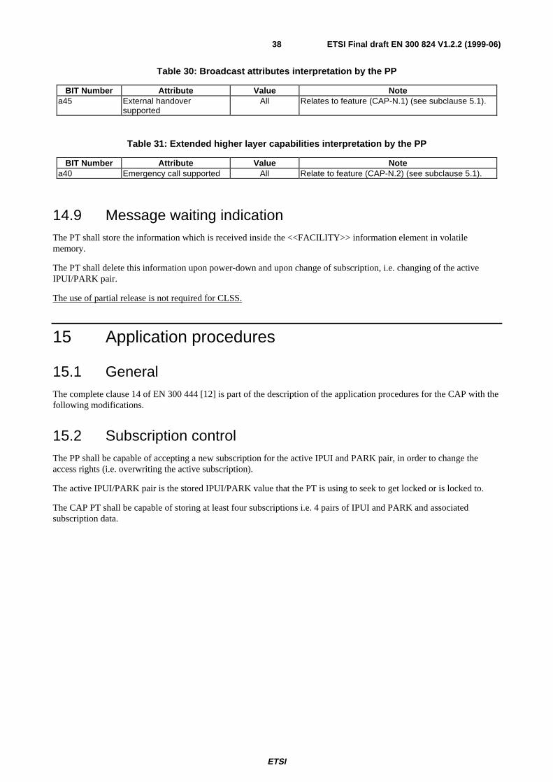
ETSI
ETSI Final draft EN 300 824 V1.2.2 (1999-06)38
Table 30: Broadcast attributes interpretation by the PP
BIT Number Attribute Value Notea45 External handover
supportedAll Relates to feature (CAP-N.1) (see subclause 5.1).
Table 31: Extended higher layer capabilities interpretation by the PP
BIT Number Attribute Value Notea40 Emergency call supported All Relate to feature (CAP-N.2) (see subclause 5.1).
14.9 Message waiting indicationThe PT shall store the information which is received inside the <<FACILITY>> information element in volatilememory.
The PT shall delete this information upon power-down and upon change of subscription, i.e. changing of the activeIPUI/PARK pair.
The use of partial release is not required for CLSS.
15 Application procedures
15.1 GeneralThe complete clause 14 of EN 300 444 [12] is part of the description of the application procedures for the CAP with thefollowing modifications.
15.2 Subscription controlThe PP shall be capable of accepting a new subscription for the active IPUI and PARK pair, in order to change theaccess rights (i.e. overwriting the active subscription).
The active IPUI/PARK pair is the stored IPUI/PARK value that the PT is using to seek to get locked or is locked to.
The CAP PT shall be capable of storing at least four subscriptions i.e. 4 pairs of IPUI and PARK and associatedsubscription data.
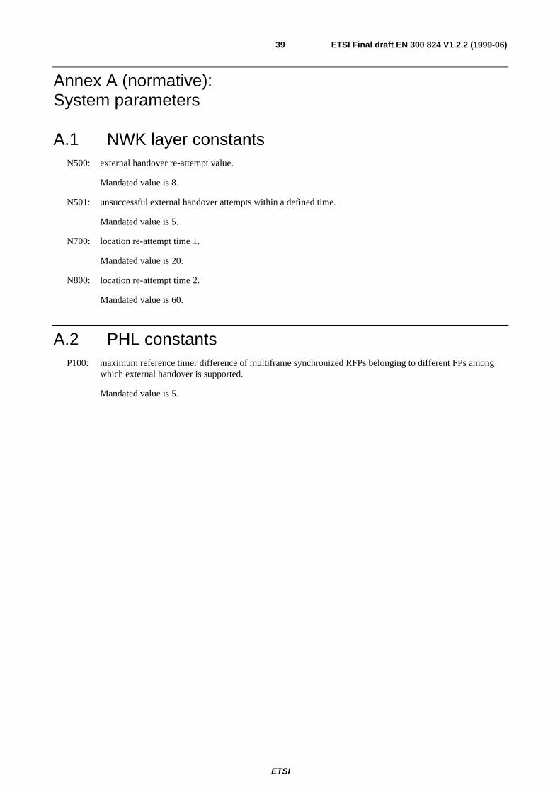
ETSI
ETSI Final draft EN 300 824 V1.2.2 (1999-06)39
Annex A (normative):System parameters
A.1 NWK layer constantsN500: external handover re-attempt value.
Mandated value is 8.
N501: unsuccessful external handover attempts within a defined time.
Mandated value is 5.
N700: location re-attempt time 1.
Mandated value is 20.
N800: location re-attempt time 2.
Mandated value is 60.
A.2 PHL constantsP100: maximum reference timer difference of multiframe synchronized RFPs belonging to different FPs among
which external handover is supported.
Mandated value is 5.

ETSI
ETSI Final draft EN 300 824 V1.2.2 (1999-06)40
Annex B (informative):PP locking procedure for on air subscriptionThis procedure is given in annex A of EN 300 444 [12].

ETSI
ETSI Final draft EN 300 824 V1.2.2 (1999-06)41
Annex C (informative):Void

ETSI
ETSI Final draft EN 300 824 V1.2.2 (1999-06)42
Annex D (informative):Tones, progress indicator and U-plane connectionSee annex B of EN 300 444 [12].

ETSI
ETSI Final draft EN 300 824 V1.2.2 (1999-06)43
Annex E (informative):PARI and SARI use for CTM roamingA CTM user subscribes to the CTM service offered by a CTM service provider. The CTM service provider provides theCTM service using the equipment of one or more network operators. These network operators can be of different nature:public, business and/or residential. The area of mobility provided to the CTM-user depends on the geographical areacovered by the totality of equipment of the network operators with whom his service provider has a relationship.
The CTM service provider is identified by one single and globally unique CTM service provider identity, the SP-id.
The network operator equipment is identified by a range of network operator equipment identities, the NO-id's. Morethan one NO-id can be assigned to the same network operator.
As part of the agreement between CTM service provider and network operators, all involved network operators willadminister the SP-id.
Radio base stations of all involved network operators will broadcast the SP-id of the CTM service provider in additionto their own local network equipment's NO-id.
CTM users have a contract with the CTM service provider and as part of the contract they are given the SP-id by meansof which they can recognize those parts of the network that take part in the provision of the CTM service for thatparticular CTM service provider. This SP-id is stored in the user's cordless terminal.
While roaming around, the CTM terminal uses the SP-id to determine whether it has access to local radio base stations(by comparing the broadcast SP-id with its own stored SP-id). If it has access, then the NO-id of the local base station isused as an indication of the location within the network.
NO-ids are structured in such a way that a terminal, while moving within the domain of a SP-id, can determine whetherhandover or location registration is required (by comparison of the current NO-id with the newly detected NO-id of aneighbouring piece of network operator equipment).
Both the SP-id and the NO-id are mapped to the single DECT concept of "Access Rights Identities" (ARI). However itis important the realize that the application is principally different.
The NO-id is kept in the DECT Fixed Part as the Primary Access Rights Identity (PARI) and is broadcast as part of theRadio Fixed Part Identity (RFPI). Separate PARI values are assigned to each DECT Fixed Part.
The SP-id is kept in the DECT Fixed Part as a Secondary Access Rights Identity (SARI) and is broadcast (but lessfrequently) by all radio base stations in addition to their RFPI.
In the CTM terminal the SP-id is kept as the user's Portable Access Rights Key (PARK) in association with the user'sIPUI.
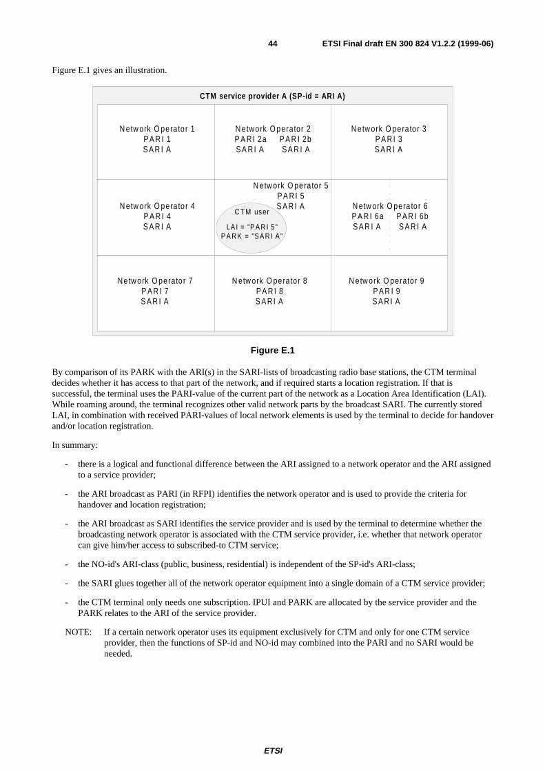
ETSI
ETSI Final draft EN 300 824 V1.2.2 (1999-06)44
Figure E.1 gives an illustration.
N etw ork O pera to r 1P A R I 1S A R I A
N etw ork O perator 2P A R I 2a P A R I 2bS A R I A S A R I A
N etw ork O pera to r 3P A R I 3S A R I A
N etw ork O pera to r 4P A R I 4S A R I A
N etw ork O pe ra to r 5P A R I 5S A R I A
C T M user
LA I = "PAR I 5"PA RK = "SAR I A"
N e tw ork O perato r 7P A R I 7S A R I A
N etw ork O pera to r 6P A R I 6a P A R I 6bS A R I A S A R I A
N etw ork O pera tor 8P A R I 8S A R I A
N etw ork O perator 9P A R I 9S A R I A
CTM service p rovider A (SP-id = ARI A )
Figure E.1
By comparison of its PARK with the ARI(s) in the SARI-lists of broadcasting radio base stations, the CTM terminaldecides whether it has access to that part of the network, and if required starts a location registration. If that issuccessful, the terminal uses the PARI-value of the current part of the network as a Location Area Identification (LAI).While roaming around, the terminal recognizes other valid network parts by the broadcast SARI. The currently storedLAI, in combination with received PARI-values of local network elements is used by the terminal to decide for handoverand/or location registration.
In summary:
- there is a logical and functional difference between the ARI assigned to a network operator and the ARI assignedto a service provider;
- the ARI broadcast as PARI (in RFPI) identifies the network operator and is used to provide the criteria forhandover and location registration;
- the ARI broadcast as SARI identifies the service provider and is used by the terminal to determine whether thebroadcasting network operator is associated with the CTM service provider, i.e. whether that network operatorcan give him/her access to subscribed-to CTM service;
- the NO-id's ARI-class (public, business, residential) is independent of the SP-id's ARI-class;
- the SARI glues together all of the network operator equipment into a single domain of a CTM service provider;
- the CTM terminal only needs one subscription. IPUI and PARK are allocated by the service provider and thePARK relates to the ARI of the service provider.
NOTE: If a certain network operator uses its equipment exclusively for CTM and only for one CTM serviceprovider, then the functions of SP-id and NO-id may combined into the PARI and no SARI would beneeded.

ETSI
ETSI Final draft EN 300 824 V1.2.2 (1999-06)45
Annex F (normative):Class 2 synchronization requirementsA Class 2 synchronization for a CAP FP shall fulfil the requirements as specified in EN 300 175-2 [2], annex C with thefollowing modifications.
The rear falling edge of a transmitted synchronization pulse shall occur at the output port of the master FP 15 µs ± Tt µsbefore T0 of any RFP on the master FP.
Tt = 2 µs.
T0 of any RFP on a slave FP shall occur Td µs after the rear falling edge of the synchronization pulse at the input of aslave FP.
Td = 15 µs ± 2 µs.

ETSI
ETSI Final draft EN 300 824 V1.2.2 (1999-06)46
Annex G (normative):Synchronization requirements for fixed partsPublic systems shall provide intersystem synchronization and shall have either GPS synchronization and a Class 1 orClass 2 synchronization output port or a complete Class 1 or Class 2 synchronization port (input and output). This willallow absolute time synchronization via GPS or wired mutual synchronization if an operator requires localsynchronization between fixed parts.
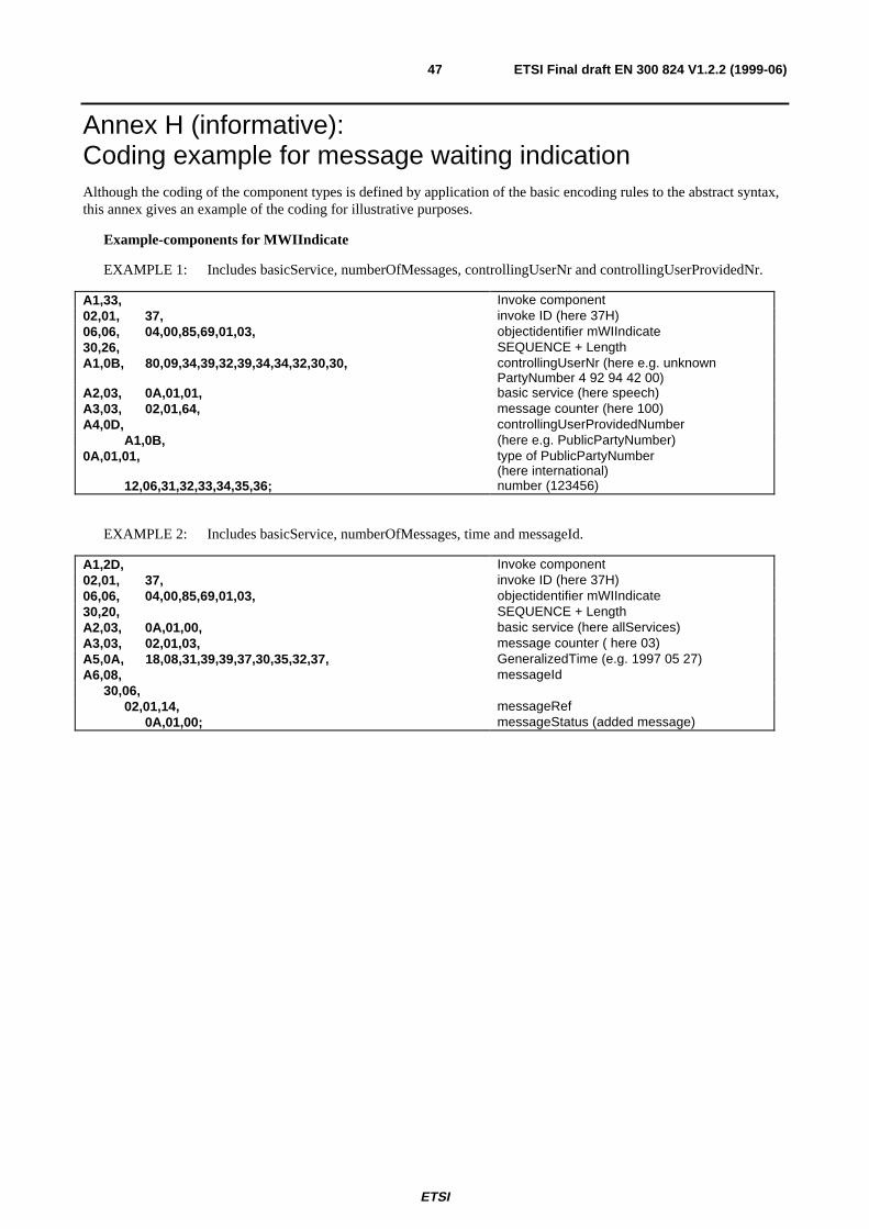
ETSI
ETSI Final draft EN 300 824 V1.2.2 (1999-06)47
Annex H (informative):Coding example for message waiting indicationAlthough the coding of the component types is defined by application of the basic encoding rules to the abstract syntax,this annex gives an example of the coding for illustrative purposes.
Example-components for MWIIndicate
EXAMPLE 1: Includes basicService, numberOfMessages, controllingUserNr and controllingUserProvidedNr.
A1,33, Invoke component02,01, 37, invoke ID (here 37H)06,06, 04,00,85,69,01,03, objectidentifier mWIIndicate30,26, SEQUENCE + LengthA1,0B, 80,09,34,39,32,39,34,34,32,30,30, controllingUserNr (here e.g. unknown
PartyNumber 4 92 94 42 00)A2,03, 0A,01,01, basic service (here speech)A3,03, 02,01,64, message counter (here 100)A4,0D, controllingUserProvidedNumber
A1,0B, (here e.g. PublicPartyNumber)0A,01,01, type of PublicPartyNumber
(here international)12,06,31,32,33,34,35,36; number (123456)
EXAMPLE 2: Includes basicService, numberOfMessages, time and messageId.
A1,2D, Invoke component02,01, 37, invoke ID (here 37H)06,06, 04,00,85,69,01,03, objectidentifier mWIIndicate30,20, SEQUENCE + LengthA2,03, 0A,01,00, basic service (here allServices)A3,03, 02,01,03, message counter ( here 03)A5,0A, 18,08,31,39,39,37,30,35,32,37, GeneralizedTime (e.g. 1997 05 27)A6,08, messageId
30,06,02,01,14, messageRef
0A,01,00; messageStatus (added message)

ETSI
ETSI Final draft EN 300 824 V1.2.2 (1999-06)48
BibliographyThe following material, though not specifically referenced in the body of the present document (or not publiclyavailable), gives supporting information.
- ETS 300 650: "Integrated Services Digital Network (ISDN); Message Waiting Indication (MWI)supplementary service; Service description".

ETSI
ETSI Final draft EN 300 824 V1.2.2 (1999-06)49
History
Document history
V1.2.1 August 1998 Public Enquiry PE 9849: 1998-08-07 to 1998-12-04
V1.2.2 June 1999 Vote V 9934: 1999-06-07 to 1999-08-20