corbin technical bulletin volume 4
DESCRIPTION
bullet handloadTRANSCRIPT

Power Swaging
Corbin Technical Bulletins,Volume IV
TB-4
David R. Corbin
Published by
Corbin Manufacturing & Supply, Inc.PO Box 2659
White City, OR 97503

Power Swaging
Corbin Technical Bulletins,Volume IV
TB-4
© Copyright 2004 David R. Corbin
All rights reserved. Duplication by any means, printed or elec-tronic, is prohibited without the express written permission of the
copyright owner.
Published in the U.S.A. byCorbin Manufacturing & Supply, Inc.
600 Industrial CircleWhite City, OR 97503
(541)-826-5211Fax: (541)-826-8669
http://[email protected]

Table of Contents
Introduction ................................................................................... 5
Design of Power Swaging Systems ......................................... 13
Swaging Pressures ..................................................................... 34
Lead Wire Production ............................................................... 43
CHP-1 Hydro-Presstm Set-Up ................................................... 55
CHP-1 Hydro-Presstm Pressure Control .................................. 71
CHP-1 Hydro-Presstm Operation .............................................. 77
Power Jacket-Making ................................................................ 90
Power Bullet Swaging .............................................................. 101
Power Swaging Business Tips ................................................ 117
Production Volume .................................................................. 122
Tables and Formulae ............................................................... 132

Power Swaging
Corbin Technical Bulletins,
Volume IV
TB-4

Page 5
Introduction
Power swaging, in the context of this book, is the production ofbullets (the projectile portion of a cartridge, not the loaded rounditself) using precision dies operated at room temperature underextremely high pressures. In custom bullet making, the pressure isgenerated by means of a hydraulic powered press, controlled byelectronic sensors and logic circuits, applied through a tough,precisely-fitted punch in one or both ends of the die cavity.
The press pushes a moving ram, which generally holds the die(unlike reloading presses, where the die is held fixed in the presshead). The internal punch travels inside the die along with the ram,and is used to eject the bullet as well as to seal one end of the die. Theexternal punch is held fixed in the press head but is adjustable formaximum insertion by means of its threaded floating punch holder.
Swaging itself, whether by hand or power, offers high precision,speed, and safety plus a degree of versatility known to few otherbullet-making processes. A vast array of bullet styles can be madewith one rather simple set of tools. Changing calibers (taken to meandiameter of bullet, here) requires a new die, but within one diameterof bullet, you can make almost any style, weight, or shape withchanges in technique, or modest additions to the basic tooling set.
Since no molten lead is used in swaging, safety is greater thanwith cast lead production. Swaging operations can be run from smallspaces, without the need for as much ventilation and no fire insur-ance worries. A major bullet business can be developed in one�sgarage or workshop (many have been, already). Versatility, speed,safety, and precision all give swaging a considerable advantage overother means of making bullets.
Power swaging adds three factors that you cannot achieve, atleast not as easily or well, with hand powered presses:
(1) Power systems can develop higher pressures than handpress, using larger dies and punches, and can generate these pres-sure levels under extremely precise control at all times, whichpermits tooling designs impractical with hand systems. Full poweris applied from the start of the stroke, not developed only near theend as with compound leverage presses, making longer draws andextrusions possible.

Power Swaging, Page 6
(2) Power systems are tireless and can be operated constantly,around the clock if need be, without any change in the quality of theproduct. An honest hand-press operator will admit that it is difficultto maintain consistent, long runs because the muscles tire and one'ssense of feel becomes dull with hours of repeated labor.
(3) Power systems can be built with the skills of an experiencedbullet-maker designed into their logic and sensing circuits, makingit possible for virtually unskilled labor to produce as good a bullet,consistently, as the system designer.
Greater power, tireless operation, and built-in expertise allcombine to give the owners of power swaging presses the ability to�clone� their efforts: if they develop a good design and find themarket greater than one person alone can handle, they can purchaseanother press and set just about anyone to work making the bullets.The quality is both in the designer's ability to make something good,and the ability of the press to give repeatable accuracy without anyparticular level of skill required from the operator.
A major difference between this kind of �smart� press, andsimply hooking a hydraulic cylinder to the end of a manual press, isthe built-in sensing of pressures, speed, position, and timing. Goodquality comes from consistently applied stroke, speed, pressure, andtiming. None of these can be achieved with an ordinary hydrauliccylinder/pump arrangement attached to a manual press.
There is no method of feedback and control in a simple slam-bang press. One cannot expect to use log-splitter hydraulics andwork with tooling that is designed to hold tolerances in the range of0.00005 inches at pressures that can exceed two thousand atmos-pheres! The materials require time to flow. They do not instantlytake on the shape of the die. It may seem that way, and we may eventalk about instant forming of the parts. But in reality, most of theoperations require milliseconds of approaching the maximum pres-sure, to allow the material to start to move, and to finish flowingcompletely.
Dies can be blown apart with exactly the same pressure andmaterial that works well with a slower ram speed. The difference canbe virtually undetectable to a person with a stopwatch. Only theprecision of electronic timing can catch the milliseconds of differ-ence that sometimes spell tragic failure (as in replacing a crackeddie) or excellent production rate. The press design needs to includeprecision speed, pressure and dwell timing controls.
Page 7
The special presses described in this book incorporate years ofpainstaking research and development, thousands of computersimulations, tens of thousands of dollars worth of experiments thatpushed the limits of what could be done and uncovered whatworked, and what did not.
It would be an error, at best, to assume that the same resultscould be achieved just by using more force. The point of this bookis not just the use of more force, but of correctly controlled force. Thecorrect operation may, in some instances, require greater force thancould be developed with any practical hand press, but in other casesit may be well below the limits of pressure you could develop witheven the smallest hand press.
In either case, it is not just how much pressure or force that isimportant, but how it is applied. The length and precision of dwelltime, the methods of support for the punches and dies, the materialsused to apply the forces and their resistance to change over a periodof time, the repeatability of the pressures from one bullet to the next,and the method of controlling stroke positioning and length, allaffect the quality of bullet you can produce.
Rather than hiding the tremendous wealth of knowledge thathas been built through years of constant research, I would like toshare it with you. In the short run, it would probably be wiser andcertainly more profitable to keep quiet and simply use it ourselvesto make world-class bullets. Dies last nearly forever with propercare; bullets are made to be used up with one shot. The repeat salespotential speaks for itself!
But in the long run, it is better for everyone if you know how toproduce exotic bullets from common materials, how to turn copperand brass and lead (not to mention dozens of other materials) intoadvanced bullet designs. These concepts have been used to makebullets so advanced that hundreds of new enterprises are alreadyproviding shooters with a selection of bullet performances neverbefore possible, and major bullet factories are loudly proclaimingthe �invention� of such novel ideas as bonded cores, which ourclients have been making for decades.
It is already starting to be �in the long run�, since my clients havebeen introducing new bullet concepts built on our swaging systemsfor over three decades. There are hundreds of individuals, whoprobably have interests and abilities little different from your own,now using our power swaging equipment to produce custom bullets

Power Swaging, Page 8
of remarkable performance, whose names you see every time youopen a gun magazine. This is in addition to over ten thousandshooters who build their own swaged bullets with our hand-poweredpresses and dies. Security, an enjoyable career (or second career, inmany cases), and the pleasure of being the best in a demanding fieldare the rewards these individuals reap.
This is being recognized more and more often in the firearmspress. Major articles appear periodically in popular magazinesverifying in excited tones that, yes, there really is another worldbeyond mass produced or cast bullets, and it�s populated with highlysuccessful bullet-makers, with backlogs of orders in nearly everycaliber and style imaginable!
People actually make a living producing custom bullets? Abso-lutely! It�s not uncommon for someone to quit a �regular� job, andjust stay home to make bullets after the first year or two of playingwith it. Many people do this with hand presses. But they usually donot make as much money, nor as quickly, as they could with a powersystem.
The reason is that most of the bullets which demand a high pricetoday (and are worth it, when you need the performance) are thosehaving features that are more difficult, sometimes impossible, toproduce on a hand press. You can go a long way toward that kindof performance but you can�t step over the magic boundary into thereally high profit realm without using power.
Power presses are owned by fewer bullet makers than handpresses because (surprise!) fewer people can afford them. Naturally,this gives you an advantage because you can focus on bullet designsthat would be too difficult, slow, or even impossible to build with ahand press (as well as making the same designs that compete withhand presses, but with more precise control).
You are not buying production speed so much as design ability.Speed is not the most important issue. The major mass producers ofbullets have invested hundreds of thousands of dollars in transfer,eyelet, or mechanical punch presses with progressive die sets thatcan stamp out an average of 40 bullets a minute, 2400 bullets anhour, 19,200 bullets a day, 5.76 million bullets a year. These bulletssell for five cents to fifteen cents each, because they can be marketedto the average shooter who only wants to pay the average rate foran average bullet.

Page 9
Those high-speed presses simply cannot approach the kind ofexotic bullet designs that you can make at home with a program-mable power press costing a fraction as much. And consequently,you can make bullets that will sell for fifty cents to two dollars each,to a much smaller group of buyers who know what they want and arewilling to pay for it.
The less automated a press is, the more flexible it can become.And the faster you try to make it with automatic handling equipment,the more it becomes locked into making just one caliber, one weight,one length, one shape of bullet. The process can become a snare: thefaster you go, the more equipment costs; the more it costs, the moreyou have to sell to break even; to sell more, you have to keep theaudience big and thus the price small; the lower the price, the fasteryou have to make them to show any profit... see what I mean?
If that begins to sound more and more like something you'denjoy less and less, then consider an alternative that pays as well bytaking a different direction....
Instead of buying expensive, inflexible high speed equipmentthat must compete for volume with other firms already well estab-lished on a price basis, use relatively inexpensive, versatile lowspeed equipment that produces exactly what the top end of themarket demands and puts you far beyond competition with existingmass-market firms. It's an idea to think about. Is it better to sell amillion things for a penny each, or one thing for a million pennies?You might work harder finding the market, but once it has beenlocated, the latter method certainly offers less continual effort andexpense. It's more fun.
One of the saddest facts I've learned about life is that mostpeople don't have fun with the main thing they do, the thing thatgives them their sense of place in society: their work. Right or wrong,it seems that in most situations you are what you do for a living.Shouldn't it be at least as enjoyable as the few days a year you aredoing something else?
I always thought so, and arranged my life to do things that werefun and still paid... such as, helping hundreds of people to break freefrom boring jobs and become independent bullet makers. Withsome people, it is easy to point out the obvious advantages and showthe way to reaching that goal. With a few, it is a major struggle just

Power Swaging, Page 10
to get them to look at anything but high volume manufacturing andthe required low profit per bullet that enables it. So I need to dwelljust a bit longer on the production treadmill....
The problem with excessive speed is that (1) it costs far morethan it is worth in a custom market and (2) why bother, when you�donly saturate your own small quantity of buyers with goods, forceyour price lower to survive, and wind up making less and workingmore for it! Why work for the bank, in other words, when you canhave a versatile hydraulic system working for you instead, and justadd workers and more presses if your bullets sell so well that youcan�t keep up with the demand?
Adding a second and a third press is far safer, far more profitable,and gives you backup in case you have a breakdown. There isnothing so frightening as having all your money tied up in onededicated, fast machine when the bank payment is overdue andthere is, broken, a ten-dollar part you can�t get for another twomonths! So much better, I would think, to have two or three slowermachines, all of which cost a fraction of the price of a high speedautomatic press, but which turn out the same combined volume.Then, if one has a problem, you are still operating at 66% of yourproduction capability, not shut down and out of business!
The objection raised at this point by the "high volume, low price"mentalities is that of labor cost. In a poor third-world country, banksof manually-fed power machinery are as economical as buying low-labor massive automation, but otherwise, how can a person affordto hire an operator for every press? Wouldn't it make better sense tospend the quarter-million dollars on a fully automated machine,instead of buying four or five six thousand dollar machines andpaying their operators?
Of course it would, if you stay with the low profit, high volumeconcept. If you have a market for several million bullets per year, byall means take on the bank as your partner in automation andeliminate most of the work force. But the whole point of custombullet making is high profit, low volume: investing far less in capitalitems and making higher profit items that can pay for flexible labor.
With the boutique nature of designer bullets, your operatingexpenses are primarily material and labor costs, not servicing theequipment cost. That means if the market slows, you simply don'tuse as much material or labor, and your equipment has long been
Page 11
paid for. Your business is relatively recession-proof because the topend buyers who want your bullets and can afford them in good timesare not usually affected much by the bad times. And your operationisn't tied to a constant fixed overhead. You might not have incomein a poor market, but at least your overhead stops along withproduction. With the high volume, low margin business model,when the market hits a rough spot, you are still paying for theexpensive machinery whether you can use it or not. And your majorclients are by definition those who want low prices and largevolumes, the very ones who will be hurt most by general economicdownturns.
I like to plan for the best, so I know what to do if business takesoff beyond my wildest dreams, but still, I like to have an alternativeplan for the worst that could happen. It seems to me that the businessmodel based on high quality buyers is less at risk even though it maybe more limited in ultimate potential. If you are interested inmaximum income potential and not bothered by the risk of compe-tition in a crowded field that is price sensitive, then high speed, highvolume production still makes sense. There are mass producersdoing just fine in this area. Most of them are making cast bullets.
But power swaging in this book is referring to a whole newconcept in bullet marketing, compared to the usual thinking in thecast bullet field. If you are a cast bullet manufacturer, you know whatit means to compete on five cent bullets and contracts for millionsof slugs, often with agencies who cannot afford to be loyal to qualityand who base their decisions on budgets.
Speed and volume count, more than anything. Competition isfierce. Casting is such an old method that everyone thinks they cando it. Sometimes it seems as if everyone IS doing it! Customers tendto regard bullets as interchangeable among vendors and brands.Price is king. Profits are elusive. And you move a lot of lead aroundregardless of the bottom line.
Now, in your wildest dreams, can you imagine making eleganthand-crafted bullets like fine jewelry, sought after by clients who arenot concerned by price but who only want top performance? Canyou imagine what it is like to have people begging you to sell themwhat few bullets you have on hand, offering you a premium overyour normal prices, because they have a big hunting trip coming upand they want your bullets above all else?

Power Swaging, Page 12
If that sounds unbelievable, then maybe you won�t think thepages of custom bullet makers listed in the Corbin World Directory ofCustom Bullet Makers are authentic. You might want to send one ortwo of them a request for a brochure, or order a few bullets fromthem, just to test the water a little. Or, study the custom bullet makerarticles, ads, and product reports that have been printed in populargun magazines over the past few decades by people who are alreadydoing exactly what I'm talking about.
The key to success in custom bullet making is in developingproduct performance so far beyond the mass market bullets thatprice is no longer an issue. And the cost-effective key to this kind ofbullet is usually found in a hydraulic swaging machine and its specialtooling, not in punch presses, automatic lathes, or high speedmethods of mass production.
My final argument on the volume versus quality controversy issimply this: develop your product so that it sells profitably when madeon low volume, high quality machinery. Then, with far less risk andinitial cost, you can decide whether you really need to �make themby the millions� for that market. Add the high speed machinery onlywhen you have assured yourself that you have a good product, anda market, based on the higher priced, lower volume strategy, insteadof basing your design on the need to make a certain volume per hourin order to meet a predetermined price.
With this approach, it is almost impossible to fail. With theconventional approach, only one or two businesses out of a hundredsucceeds.

Page 13
Design of Power Swaging Systems
Four power sources are practical for swaging, other than thestrength of your arm: (1) Direct rotational electric power, (2) Inertialstorage of rotational electric power, (3) Pneumatic pressure, and (4)Hydraulic pressure. The rest of this chapter is a discussion of thedesign considerations.
Direct Rotational Electric PowerDirect mechanical application of the torque from an electric
motor's shaft can be used, through a system of gears or belts, for lowpower swaging systems. It is best suited for fully-automatic systemsthat would use small calibers (under .308-inch) and soft lead coresin thin jackets, or up to .357-inch bullets with soft lead and no jacket.
Building such a device usually means driving the ram of a presswith a cam or eccentric bar, like a steam locomotive drive pistonbeing turned by the wheels instead of the other way around. This letsthe motor run constantly in one direction, avoids inertial stressesproduced by stopping and reversing direction of gears, and pro-duces a simple fixed stroke machine designed primarily for onebullet.
Practical size machines would use a motor of 1/2 to 1-1/2horsepower, reducing the speed to gain torque by operating throughgear trains or belts and sheaves. A ram speed of not over 2 inchesper second is generally desirable. The reduction from a standard1725 RPM single phase motor is a 28.75 to 1 ratio. The necessaryram force depends on caliber, material hardness, and shape of thedie, but a 10,000 pound ram force is generally adequate for all leadbullets from .357 diameter down.
A drive wheel or gear with nominal circumference of 3.14inches or diameter of two inches is just about as small as a wheelcan be made and still wrap a practical size belt or accept the powerfrom an adequate motor. So let's start with a motor shaft spinninga one inch radius (2-inch diameter) wheel (gear or sheave).
The two standard motor speeds are 3600 and 1725 RPM forsingle phase, 60-Hz. motors. The 1725 RPM motor will have greatertorque for the same horsepower, since horsepower is simply torquetimes speed. That means our one inch radius wheel will be spinningat 1725 RPM. The circumference of the wheel is 3.14 inches. The

Power Swaging, Page 14
number of inches of wheel that pass by a fixed spot in one second,then, is simply 3.14 inches times the velocity of 1725 complete turnsper minute, divided by 60 (since there are 60 seconds in one minute).
This is 90.275 inches per second. That is the equivalent linearspeed of the wheel, and it is much too fast for moving the swagingpress ram. The inertial of the components would mean a verycomplex, powerful system of automatic handling would be requiredto get them in position and back out again before the ram struck,and the results would not be too good since the torque or thrustwould be so small compared to the initial impact momentum. Leadneeds time to flow.
Slowing the linear speed down without decreasing the horse-power would give us more torque, too. So let's turn a larger wheel,having more inches around its circumference. The ratio of the drivewheel circumference to the driven wheel will be the ratio of reduc-tion in speed, since every inch of movement from the drive wheeltransfers directly into an equal distance of movement on the circum-ference of the bigger wheel.
The distance that the ram must travel to swage a bullet has tobe equal to the length of the bullet, plus a tiny amount of room forclearance so the bullet can fit easily in between the die opening andthe ram, plus the amount of alignment distance required inside thedie itself. Alignment distance must be at least the diameter of thebullet, and preferably twice that. This prevents galling and tipping ofthe precision punch that fits in the die behind the bullet. In adedicated press that was designed only to make one kind of bullet,the stroke could be shortened so it came out according to thisformula:
Stroke = 2C+1.1L
...where C = caliber and L = bullet length in inches.
With a typical .38 handgun bullet, the caliber is .3750 inches andthe length is .70 inches. The stroke, by this minimum length formula,would be 1.484 inches. This means that on the output side of oursystem of wheels (gears, sheaves and belts), there will need to be awheel with a pivot pin located 0.742 inches from the center of theshaft, and to this pin we shall attach a connecting rod to the bottomof our ram.

Page 15
An alternative would be to make a cam by mounting the centerof a wheel eccentric to the circumference, such that the differencebetween the lowest point and the highest point on the wheel relativeto the shaft center was 1.484 inches. Either way achieves the sameresults. The cam requires a method of retracting the ram, such asa stout spring or a groove in the side of the wheel with a matchingpin riding in it, the pin attached to the ram.
We know the stroke length and approximate desired speed oftravel. At two inches per second, a ram moving 2.968 inches wouldmake one complete stroke in 1.484 seconds (it must move up andback, total of 2.968 inches at a rate of 1 second for every two inches).This means the shaft turning the cam wheel must be rotating onecomplete turn in 1.484 seconds, since each turn is a complete stroke.
Now we know the rotational speed required for the driven wheel:it is 1 revolution per 1.484 seconds, which is the same as .67385445turns per second, or 40.431 turns per minute. The reduction ratiofrom input to output of our wheel system must take the 1725 RPMof the motor down to 40.431 RPM for the cam wheel that drives theram. This is a ratio of 1725 divided by 40.431, or 42.665 to 1.
If you think about it, you will see why mechanical rotation is notusually practical as a power source on anything but small systemsrequiring small ram forces. The cost of the gears and wheels, andthe power loss through the system of belts, would be unacceptable.
The ratio of circumferences is in direct proportion to the speedratio, while the ratio of diameters is a square root proportion. Witha drive wheel of 2-inch diameter (1-inch radius), and circumferenceof 3.14 inches, the circumference of the driven wheel or cam ina single reduction system would have to be 133.97 inches! Thediameter of this huge cam driver would be 42.64 inches, or about3.55 feet!
Of course, with a train of gears, this could be handled nicely ina smaller package, but it would be expensive. Using a worm geardrive is the most practical method of reducing the speed. Thefriction caused by the high ratio worm gear reduces power consid-erably.
In a clock, high ratio reduction systems are practical becausethe total torque transfer is small. The gears can be tiny, fragile thingsthat pack tightly into a small space. In a machine like this, the torque

Power Swaging, Page 16
transfer is large. The gears must be beefy to handle it. Being strongand also having a high reduction ratio means they are going to belarge and costly. It also means there will be quite a bit of power loss.
A power reloading press can utilize a cam or worm-gear drivesystem without undue cost because the required power is quite lowcompared to swaging. The amount of pressure required to size acase or seat a bullet is a fraction of the amount used to cold-flowmetal into the shape of a bullet.
People who have not done the math or tried building swagingsystems before often wonder why there are no multi-position swag-ing presses, either hand or power. Not only would the different stepsof swaging a bullet require different amounts of pressure andinsertion depth, but applying all of them in a three to six stage bullet-forming operation would mean building a huge power system to runit.
Inertial Storage of Rotational Electric PowerFor most applications involving direct mechanical force, the
energy is first stored in a heavy mass, by spinning a flywheel. As thespeed of the flywheel builds up, it stores more energy. When itreaches designed speed, a trip is engaged to catch a tooth or gear onthe moving flywheel and transfer its energy to a ram.
This system allows the motor to supply energy over a longerperiod of time than just one stroke. The motor can feed energy intothe flywheel while components are being moved under the die,ejected, and during the return stroke. Typically, this kind of systemonly has full power at the bottom of the stroke (assuming the ramis on top, as with most punch presses). The cam or connecting-rodmechanism also develops its full power (minimum speed, maxi-mum force) at the ends of the stroke.
This is an important concept to understand. The swaging pro-cess normally requires very little force while the component ismoving into the die. Most of the ram force is required at the end ofthe stroke, when the components have stopped moving and arebeing expanded under high pressure. So, for swaging operations,the mechanical system seems to be ideal.
But when you include jacket forming, drawing, and other opera-tions that utilize a great deal of force right from the entry of thecomponent into the die, these systems fail to deliver the necessaryenergy in the right form until the press reaches massive size

Page 17
compared to air or oil pressure presses. The typical size of pressrequired for single station bullet swaging needs at least a ram traveltwice the length of the bullet, and a tonnage rating of between tenand twenty five tons.
The tonnage of a punch press is not quite the same thing as theactual ram force of a fluid power system, because the tonnage is onlygenerated in full when the press has extended its stroke all the way.The ram is attached through a crankshaft or toggle in the typicalpunch press design. The energy stored in the spinning flywheel isapplied to the crankshaft while the ram is at the top position, and theleverage that multiplies the force depends on the angle of theconnecting rod.
The force available to flow the bullet materials when the ram isstarting down, or when it is half an inch above the full stroke length,is considerably less than rated tonnage. It is necessary to purchasea much larger tonnage press in order to have the desired ram thrustavailable higher in the stroke.
Punch presses, eyelet presses, transfer presses, and other varia-tions on the flywheel press are often used to punch and form sheetmetal. With fraction of an inch thicknesses, the rated tonnage isclose to being the amount available to punch, shear, and bend thework piece. But when long tubular parts are being formed, or whendeep drawing cylinders like bullet jackets, full force may be requiredmuch higher in the stroke.
Inertial presses of twenty to fifty tons rated force are typicallyused for high volume production. The presses themselves generallyare in the middle five to low six figure price range, new, withouttooling. They require a fairly large operating area with moderatelyhigh ceiling, and generally use commercial three-phase powermotors. The basic open back, inclined bed punch press can be usedwith a stack of dies, to make several drawing reductions in one pass.
OBI presses are usually the least costly design and are availablein small tonnage sizes. I once used a little two-ton OBI press that Ibought at a surplus machinery sale and carried to the trunk of my240z sports car, then drove home with it comfortably resting on myovernight bag! It was far too small for bullet making but punched nicehole patterns in the cover for an electronic device that I wasmanufacturing. It was almost worth designing products just to seethe little fellow punch the parts.

Power Swaging, Page 18
Eyelet presses are a kind of "dial feed" single station press. Theyuse a rotary feed mechanism that positions the part under the ram,and moves it around to eject and load more parts. Transfer pressesare usually multi-station, which means that the ram is attached to anumber of punches or die shoe assemblies, all in a row. The workpiece, which is normally a continuous strip of metal, is fed into thefirst station, and is advanced by a clever "shuttle feed" device fromone position to the next.
The strip is fed into the first station with a strip feeder, which canuse friction rollers or one-way spring-loaded gates that push the stripone direction but slide over the strip on the back stroke. Or air clampcylinders can be used to grasp and move the strip forward. At the firststation, the strip is cut or punched to make a "coin", for deep drawingoperations. The coin may be left attached by thin flanges to the strip,so that the strip can be used to advance the part, or it may be cut freefrom the strip.
The shuttle feed is made as two halves of a multiple part clamp,which spread apart (open), move backward one position, closetogether (clamp), and then move forward one position. This motionis repeated over and over again, and has the effect of grasping a part,moving it to the next station, releasing it over the die hole, andmoving back to get the next part.
I mentioned �die shoes� without explaining them. These arestandard methods of holding and aligning the punches and dies sothat they remain in alignment when you remove them from thepress. The typical die shoe consists of a base plate, two or morehardened and ground support rods which are fitted with bearingswithin a sliding plate.
The base and sliding plate chomp up and down, powered by thepress ram and supported within the opening of the press by beingbolted or clamped in place. You can usually change the actual diesand punches fairly easily in the die shoe, which is a sort of interme-diate mechanism between the press and the dies, providing theprecision alignment instead of the press having to be built with highaccuracy components to hold the dies and punches. .Die shoes areavailable in different configurations and sizes as more or lessstandard items, separate from the custom dies themselves.
In the Corbin swaging presses, we eliminate the die shoe andbuild the precision into the press head itself, and then standardizethe dimensions of the dies and punches as far as their methods of

Page 19
holding and alignment, retaining the custom dimensions for theactual parts. We can do that, saving you thousands of dollars overthe typical punch press system, because we are limiting the kind ofproducts formed to a fairly small range of lengths and diameters intubular forms (jackets and bullets, not car fenders, napkin holdersand flashlight cases). The die shoe is a design feature that helps thepunch press handle an extreme range of product sizes and shapescompared to the bullet and jacket making field, something you don�tneed if the press itself is designed for that field.
As you can see, the punch press is extremely versatile and canbe used for anything from automobile fenders to flashlight cases. Butthe various complex feed devices and the die and punch setsthemselves are not flexible. They are made to do one specific part,of one size, material, weight, shape... and they are very expensivebecause they must be built specifically for you, for each part youwant to make.
When it comes to bullet swaging, a person wanting to use highspeed punch presses will need to buy the press (a used one in the tento fifty thousand dollar range would be about average investment)and then find a die designer to work out the blueprints and specifi-cations for feeds and dies for the specific press to make your parts.
Once the tooling engineer has worked out the design, you needto take it to a tool and die shop and have them actually construct thetooling. Some of it will be universal, off-the-shelf component mod-ules, and some of it will be built to blueprints. Once the tooling hasbeen constructed according to your blueprints, you then need to getan experienced punch press setup person to put it all together anddebug it, because no one involved in the process is responsible forfinal operation except you.
If the material tears or punches through instead of drawing, or ifthe parts stick on the punches, the tool and die shop will only beresponsible for having made the parts to the tolerances specified onthe blueprint. The tooling engineer will only be responsible for hisdesign and not for the implementation of it, so that if any parts arenot made correctly he is not going to take responsibility. And if youuse a material with a different temper, tolerances, or grain structurethan was specified, no one is responsible for it working but you.
Once when I was backlogged two and three years with jobs andsimply didn't have enough available time to design my own jacketdrawing dies for a high production press, I hired a firm who said they

Power Swaging, Page 20
had deep drawing experience to both design some new jacket-drawing tools and build them. That way, the opportunity for finger-pointing was reduced since one firm would be responsible for bothdesign and construction. But after four months and a few thousanddollars spent on "progress payments", the company gave up. Theycould not make the punch press form soft copper into jackets. DidI get my money back? Are you kidding?
What I got was what you or anyone else would get: a box full ofparts including the die shoes and dies, a bill marked paid, and asuggestion to use some other material. That's just how it is with thetool and die business. You pay for people to try and you take yourchances unless you know for certain that you already have a designwith the correct tolerances and dimensions, and that if someonefollows your plan exactly in making the tools, they will work.
If you leave it up to someone else to design your tooling, youmight possibly have some recourse if in the end it doesn't work, butthe odds are very good that one of about a hundred different escapeclauses will leave you stuck with the bill and useless tools. Thereason is that if you don't know enough about it to design theblueprints yourself, you probably don't know enough about thematerials and setup to guarantee that you follow precisely what thedesigner intended. He might be able to make it work if he were theone who built the dies and set it all up, bought the material and ranthe press. But of course, he doesn't do most of that. Someone elsedoes. So at every step of the way, there is finger-pointing. It is alwayssomeone else's fault.
A few years later, when I had more time and some good die-makers working for me, we built tooling that drew pure copper stripinto excellent bullet jackets. It took many years and tens of thou-sands of dollars to evolve to the level we have today. And the processhas never stopped. I have no doubt that in five years, we'll be makingtools that are faster and better still. Actually, the next set we makewill have improvements that we didn't even consider necessary orpossible yesterday. And our clients get the benefit of each thing welearn. Also, we are responsible for the design and the construction,and all the client has to accept is responsibility for using the rightmaterial and following our instructions (in order to get warrantyservice for any failure to produce the part specified).

Page 21
Naturally, anyone can interfere with the operation of a precisionprocess by failing to use the right material, or by using it incorrectly.But your level of responsibility is orders of magnitude less, when youbuy a "turnkey" package designed around a specific material andguaranteed to make a certain part to specific tolerances.
You can't buy different material and expect it to always producethe same results as the material used to design the tools, nor can youdecide to skip some steps or make changes in the lubrication, speedof operation, or physical parameters of the material and then holdthe die-makers responsible if it doesn't work the same as it did withthe right material and procedure. But that is a far cry from the riskyou incur with tooling up a typical transfer press.
Because the tooling for inertial presses is designed around thehandling between operations, most of the cost is in fact in the feedingof the parts rather than in the press or the forming dies themselves.It is hard to separate the feeding and forming costs, though, becausethe dies incorporate some of the feed system in most cases. As ageneral rule, the requirement for high volume, high speed operationis primarily a requirement for dedicated feeding systems for eachpart. The press and dies is slave to the feeding method that advancesthe parts through the process without human intervention.
The human hand is extremely versatile, and most people get twoof them free, the ultimate robotic feed system in regard to instantlyswitching from one part size to another. True, it is slow. That is fine,in a market where 150,000 parts per year would be saturation, andthe customers are willing to pay from fifty cents to as much as twodollars a bullet. The bulk of the gross profit goes to pay for your time,rather than going to pay for debt service on expensive machinery.
That is why the most versatile kind of press, requiring the leastinvestment and size for the most versatility and capacity, is a fluidpower press.
Pneumatic PressureThe lowest-cost fluid power system is compressed air. The field
of fluid power transmission includes both air and hydraulics. Bothgas and liquid are considered �fluids� in this application.
Air, being composed of gasses (primarily nitrogen), behavesaccording to conventional physics rules for gas. That is, it takes upless volume and becomes more dense as pressure is increased,

Power Swaging, Page 22
and it expands in volume or increases in pressure as temperaturerises. Liquids are relatively incompressible compared to gasses, sothey behave differently under pressure.
An air compressor might typically be capable of developingfrom 90 to 150 pounds per square inch of compressed air pressure.Since the typical internal die pressure required to form soft leadproperly into a bullet shape, regardless of caliber, is about 15,000to 20,000 psi (depending on die shape), a 4-inch diameter aircylinder would just barely have enough area to produce the forceto swage a soft lead .357 caliber bullet, driven from a normal aircompressor.
On the other hand, air pressure of only 90-100 psi on a 4-inchdrive cylinder allows enough ram force to swage .224 and .243 riflebullets very nicely. A pressure of 28,699 psi can be developed in a.224 inch die at just 90 psi of air pressure, using the 4-inch cylinder.
An air-driven swage press is practical for small calibers. It ispossible to build a practical press to swage .308 rifle bullets, usingonly 125 psi air pressure, and a six-inch diameter drive cylinder.The internal die pressure can reach 37,949 psi with such a combina-tion.
How much pressure is required? That depends on the jacketmaterial, thickness, and core hardness as well as the bullet shape.It can range from a low of about 10,000 psi for soft lead with simple,easily formed ends to a high of more than 150,000 psi for heavyjacketed bullet brought to small tips. Our range of internal diepressures, practically speaking, spans a 15:1 ratio.
Internal die pressure is related to the square of the caliber, sincethe caliber is the diameter of the piston or punch that appliespressure to the material in the die. It is directly related to ram force.Thus, the ram force range has a 15:1 ratio for practical bullet formingoperations. Ram force is in squared ratio to the drive cylinderdiameter, but again in direct ratio to the drive pressure applied to thefluid or air in the drive cylinder.
With air equipment that is practical for non-laboratory use, thelargest bullet than can be formed with certainty is a .308 caliberhaving a conventional thin jacket, no boattail, and fairly standard 6-S ogive. A soft lead .357 bullet can be formed with certainty in nearlyall but the most complex nose and base shapes. Anything larger ormore pointed, or having material any harder than soft lead for thecore, is very likely NOT to form properly.

Page 23
A cylinder larger than six inch diameter is not only very expen-sive but tends to introduce other problems, such as speed ofactuation, oscillation in the system, requirements for excessive-sized feed lines to exhaust the cylinder, and multifarious conun-drums beyond the scope of this discussion. The only other alterna-tive is higher air pressure, and that is limited by the cost andavailability of regulators, fittings, filters, and other appliances tocontrol the system, not to mention the compressor itself.
Corbin built air presses for a number of years. They weremarginally effective compared to hydraulic systems, but the de-mand was great enough to justify developing them. Cost on a 4-inchbore system is reasonable and if the bullet maker understands thelimitations, and accepts them, then making .22 jackets from fired .22cases and forming .224 to .357 bullets of certain types from soft leadcan be done very nicely.
The air-over-oil system is a hybrid design wherein air pressureis applied to one side of a hydraulic cylinder, and the other side isfilled with oil. This helps to eliminate some of the problems withpneumatic systems in regard to the �spring� or compressibility ofair. It does not change the forces and pressures possible, but merelyadds some additional control.
One of the problems with air systems is the instant action you getwhen you apply compressed air to the cylinder. It is restricted onlyby inertia and friction, which isn�t a lot of restriction, so it fliesforward and back with virtually impact forces, a little bit like a punchpress. The speed doesn�t really allow time for some materials toflow. It rips and tears the ends off bullet jackets, for example, and cangenerate rather excessive shock waves that crack swaging diesbecause the material acts as if it is much harder when you don�t giveit time to flow from a freshly applied force.
The air-over-oil hybrid system gives more control over speed,since you can more easily meter the oil flow through a restrictorvalve (speed control) than you can with air flow. Air speed controlsare available but they are not usually as precise, reliable, and wide-ranging in their flow ratio adjustment.
When you are swaging a lead core, there is normally a physicalstop set up so that you don�t continue to extrude lead until the entirecore is gone. With core seating and point forming, sometimes aperson wishes to use a certain pressure level as the sensing point tostop pressing. With hydraulics, the pressure is reached and the

Power Swaging, Page 24
material is compressed in the die very uniformly. The ram can bestopped almost instantly by switching a valve, run by a pressuretransducer.
With air, you can shut off the valve and yet the ram will continueto move for a noticeable time. Inertia and expansion within thesystem can cause problems on larger systems with movement whenit should not be taking place. This is because air does compress, andshock waves can travel through it, causing movements after a valveis closed.
With hydraulics, the material transfers pressure instantly (ornearly so) throughout the entire system. The application or removalof pressure at one point has an almost immediate effect on theentire system. Movement is much more precisely limited by control-ling the pressure. For bullet swaging, hydraulic power presses offersignificant advantage over air presses.
The main physical difference between air and oil systems is thecompressibility of the fluid: air is highly compressible, hydraulic fluidis almost incompressible. Hydraulic systems act more like flexiblemetal shafts, so that a shove on one end almost instantly transferspower at the other end. Air acts more like a big spring, where a pushon one end eventually travels through the spring as it collapses inrelation to the force.
Hydraulic pressure. Hydraulics originally meant water power. A hydraulic-electric
generator is a water-powered turbine. But in the fluid power field,it has come to mean oil or synthetic oil under pressure. Hydraulicfluid can be a water-based synthetic material or a light oil.
The oil is not designed for lubrication, but has low foaming whensplashed around, low capacity to adsorb air and gasses underpressure, and is highly incompressible. It is made to maintainviscosity under high temperature and to transfer heat as well aspossible. Certain pump and valve components are designed usingmaterials that are compatible with either distilled petroleum orsynthetic based hydraulic fluids. The solvent action of some fluidswill destroy these components, so it is important to use the recom-mended hydraulic fluid.

Page 25
Never mix types of hydraulic fluids unless the manufacturer ofeach fluid agrees that they are compatible. Never replace hydraulicfluid with motor oil or brake fluid. Just because it says "oil" doesn'tmean you can use it on your salad, or in a precision press.
Another reason for using the correct fluid is that the pump israted to handle a certain load, in a certain temperature range, witha specified viscosity or flow resistance of oil. If the fluid does notmatch this pressure and temperature range, it will break down andleak past the pump vanes. The pump will cavitate, the oil willfurther heat, and the pump seals can be destroyed. Further heatingcan cause pump seizure, destroying the rotor or the housing.
This is mentioned at the outset because it is important to use thecorrect fluid in a hydraulic system, and there seems to be quite a bitof confusion over what hydraulic fluid is. There are many grades andformulations, and quite a few are incompatible with each other andwith the pump and valve components of some systems.
The hydraulic fluid used in Corbin presses at this writing isChevron AW-46, which has cross-referenced equivalent numbers toother brands and is commonly available from hydraulic componentsuppliers, and from commercial oil distributors. This is an anti-foaming fluid that reduces cavitation and is usable over a fairly largerange of temperatures. Extreme cold is not a suitable environmentfor operation.
The room in which the press is stored and used should be keptin the normal comfort range for human habitation (from 65 to 85degrees F, preferably closer to 70 degrees F.). The viscosity of thehydraulic fluid increases with lowered temperature, so that operat-ing the press or even starting the motor in a cold environment candraw too much current and blow a fuse or trip the 20 ampere circuitbreaker/power switch.
If it is necessary to store the press at lower temperatures, theroom should be slowly warmed to the proper operating temperatureso that condensation is avoided. Once we received a Hydro-pressfor repairs, and every exposed steel component was coated with alayer of red rust. The press had been stored in an unheated shed,which was warmed up whenever the weather changed or the ownerfired up a wood stove in preparation for making a few bullets.Moisture condensed on the precision steel components, which theowner failed to lubricate. The repairs consequently included replac-

Power Swaging, Page 26
ing parts that would have been perfectly fine for several lifetimes ifthe room had just been warmed up slowly and a little rust-preventiveoil wiped onto the exposed metal.
At such times, the old expression "casting pearls before theswine" comes to mind, in the sense that a person who cares enoughto research and buy the finest machine of its kind, a machine withdecades of research and development behind it, built by a die-workswith a hard-earned, worldwide reputation for careful design andconstruction, should at least care enough about their investment totry to take the most basic care of the machine. Not that I'd evercompare a client to a pig, of course.
It's their money and none of my business once they takepossession. I�m sure the people who design target pistols wouldhave choice names for me if they saw how seldom their fine productsare cleaned after a match (especially the 22�s which get cleaned soinfrequently that they might indeed bring a pig�s sty to mind). Afamily friend has an interesting turn of phrase, a result of not hearingthe term correctly and then continuing to mispronounce it until itbecame ingrained habit: the phrase is �pig stein�, which alwaysbrings to mind a �hogshead� of beer for some reason. The pistolscontinue to work fine, though, even the one�s I�ve used for fortyyears, and I do wipe them with oiled cloth now and again.
Still, lack of care seems like such a waste, especially when ittakes so little to maintain the machine virtually forever. Some of theearliest Hydro-presses are now going on 30 years of service, havingmade millions of bullets. Some of them have never had the oilchanged, and the only components replaced have been indicatorbulbs on the control panel. I recommend changing the oil and thefilter once after about 2000 hours of operation, but apparently thisis precautionary rather than a necessity. The system is closed, thereare no combustion products to contaminate the oil, and the onlyreason for deterioration is the fine particle accumulation that takesplace from normal wearing of the pump rotor vanes (which the filtershould trap).
Hydraulics have significant advantages over other drive types.A compact power system can deliver extreme pressures at moder-ate speeds. Control can be precise and easily adjusted with elec-tronic sensors and logic. This opens the door to automatic controlover system variables such as pressure, timing, speed and position.

Page 27
The skill required to produce good bullets on a hand pressincludes the ability to sense a consistent pressure level by feel of thehandle and ram resistance, and the sense of timing necessary to holdthe ram forward the same time on each stroke. The electronics of aproperly-designed hydraulic system can eliminate the need for thisskill, and maintain consistency far beyond that possible by manualmethods.
Hydraulic power by itself is not the answer to successful bulletproduction. Merely connecting a pump to a cylinder and slammingit back and forth in a mindless display of raw force will NOT makegood bullets, and it probably will break dies and possibly injure theoperator.
Control over the force, in the form of a logic and sensing systemthat is able to detect smaller variations than a person could possiblynotice, and to act on them with greater speed than is possibleby hand, repeating the expert performance reliably no matter howlong the production run � that is the secret of making good bulletsby hydraulic power.
The electronic system does not replace the operator, but ex-tends his ability by doing his will more quickly and more precisely.It is not a �robot� that replaces the skilled hands, but a tool placedin those hands � a tool vastly more sensitive and at the same timemore powerful than anything else available, but still under thecontrol of the operator, and depending on his knowledge or on theknowledge of the person who set up the press. Once the knowledgehas been applied, and the system is set up to make a perfect bulletof a given weight and shape, then the system can continue to repeatthat performance regardless of who comes along to drop the partsinto the die and press the buttons.
The bullet maker can walk along a row of such machines, settingeach one up to do his bidding, check and adjust them to obtain theresults he desires, and then put someone to work dropping parts intothe die and pressing the buttons for the rest of the week.
This is the great advantage of such a system. Not only is it morepowerful, for less cost, than anything else available, but it is capableof duplicating the skill of the bullet-maker, giving anyone the abilityto produce a high quality bullet. At that point, it does become areplacement for skilled hands�but only after receiving �orders�from the higher authority of the bullet maker.

Power Swaging, Page 28
The hydraulic system can apply the same force at the bottom,middle, and top of the stroke. It does not have a limit on where theram must be to develop maximum power. This means that opera-tions such as jacket forming and bullet reduction are much easier.It means that lead wire extrusion is practical.
Practical hydraulic components of industrial quality (not farm orautomotive components, which are built with dirty working environ-ments as a main concern, and have life-spans more suitable for theaverage auto or combined growing seasons than industrial hydrau-lics) can be obtained with reasonable pricing with a maximumworking pressure of 2000 psi (shock-rated) and 5000 psi staticpressure (non-shock). The design of Corbin systems take advantageof the cost curve and use a 2000 psi pump so that components canbe readily matched.
Higher pressures put the controls in a higher price category,while lower pressures reduce the range of functions or require muchlarger diameter drive cylinders and thus increase the cost of thesystem out of proportion to the benefits. Pressure also has a relation-ship to the kind of hydraulic lines used to plumb the press. Higherpressure on flexible hydraulic hoses places more torque or bendingforce on the connections and components except for straight-lineconnections, and is more likely to cause seepage or leaks. The entiresystem, including the weight and thickness of the cabinet and frame,is designed to match the pressure, bending movement of lines, andultimately the horsepower of the drive motor.
Rigid steel line costs less than flexible hose, but it is more difficultto fit and replace. It is subject to fracture at the flared fittings fromvibration or repeated stress, which causes seepage of oil. Vibrationand shipping stresses, such as sudden stops and accelerations, canshake heavy components or flex the cabinet slightly, and loosen orcrack the connections made with solid steel tubing.
Replacement of steel tubing requires either precisely preformedbends and lengths of exactness that may not be practical, or thecustom-fitting of tubing by the installer using tubing benders, cut-ters, flaring tools and wrenches.
Flexible hydraulic tubing uses more expensive fittings and isitself considerably more costly than steel line, but if properly sizedwith generous loops, it can better handle mechanical stress and canalso be replaced with nothing more than an open-end wrench. Thedesign of the cabinet, routing of the hoses, and mounting of compo-

Page 29
nents becomes more critical with flexible tubing, since the oilpressure will try to "uncoil" loops or straighten U-bends. The forcecan be enough to break mounting bolts, bend or break housings andunscrew the connectors if the effects of hose torque are not takeninto consideration. In some cases it may be necessary to secure theloops by mounting to solid structural supports so that the torque isnot so great on the fittings.
Ram thrust, drive pressure, and internal die pressure are relatedbut not the same thing. It is important to understand the differences.With a range of from 100 psi to 2000 psi on the gage (drive pressure),a cylinder of 3.25-inch diameter can produce a ram thrust of 829.58to 16,591.54 pounds. This thrust is independent of caliber, depend-ing only on the applied pressure and cylinder diameter. At 2000 psion the gage, the press is developing a thrust of 8.3 tons.
This thrust, however, must be channeled through the face of apunch to apply pressure within the die. To transform the ram thrustinto die pressure, we must know the caliber (diameter) of the punch.The formula, written using computer math notation, is...
Pd = F/A
d
...in English, this means divide the force of the ram, in pounds(F), by the Area of the punch tip in square inches (A
d). Die pressure
(Pd) is in pounds per square inch. The area of the punch tip is given
by the formula...
Ad = Pi * C2 / 4
...where Pi is 3.14159.... (number of times the diameter of a circlewill go into its circumference), and C is the caliber or diameter of thepunch. You could replace C2/4 with half the caliber, or radius,squared, since the area of a circle is also Pi * r2.
As the diameter of the bullet gets smaller, the pressure that isproduced in the die with the same ram thrust goes up very quickly(in proportion to the squared caliber). Smaller calibers, then, requirefar less ram thrust than larger ones to develop enough pressure sothat the lead flows and the bullet forms correctly. Lead flows at acertain pressure, depending on temperature and exact alloy compo-sition, that is usually about 15,000 psi in a smooth-sided cylindricaldie. It takes about 20,000 psi to form a good replica of the inside ofthe die using a normal jacket over the lead.
Power Swaging, Page 30
This is not related to caliber, drive cylinder size, or oil pressure.In other words, soft lead at normal room temperature will flow wellenough for swaging at 15,000 psi no matter what the caliber. This isinternal pressure on the lead, within the die. The force that it takesto generate that pressure is very much dependent on the diameterof the die. This is why you can easily swage a jacketed bullet in asmall reloading press, in .224 caliber, but increasing it to .458 caliberrequires vastly more effort and might overstress the components oftypical reloading presses.
The figure of 15,000 psi is a bit arbitrary. Lead starts to flowunder very small stress, even at 1000 psi. There are instances wheretall buildings have been built with pads of lead sheet between theconcrete foundation pilings and the support columns, as a way tospread the force evenly and allow for some expansion movement.After years of being under pressure, the lead was found to be slowlyextruding, with a creep rate of a few thousandths of an inch per year!
The rate of lead flow under lower pressures is extremely slow.As pressure is increased, the speed of movement goes up. The rangeof 15,000 to 20,000 psi is a high enough estimate so that soft leadcores inside a normal gilding metal jacket of 0.015 to 0.027 inch wallthickness will form completely in standard bullet dies, within half asecond or less. This is long enough to get the job done at a reasonablepressure without excessive conscious effort to maintain a specificdwell time with hand press operation. (With a power press, the dwelltime can be precisely dialed up and repeated automatically.)
The pressure within the hydraulic system that is necessary toform a bullet depends on both the caliber and the size of the drivecylinder. We�ve just shown how to calculate ram force from requireddie pressure and caliber. Now, here is how to calculate the oilpressure necessary to develop any given ram force...
Ps = F/A
s
...which means, the hydraulic system pressure (Ps) equals the
ram force (F) divided by the area of the system drive cylinder (As).
The area of the cylinder, As, is equal to the square of its diameter
times Pi (3.14159) divided by 4. This is the same formula as thearea of the punch tip. We can put this all into one formula by saying
Page 31
that the gage pressure is equal to the die pressure times the squareof the die diameter, divided by the square of the drive cylinderdiameter...
Ps = P
d * C2 / D2
In the case of the Corbin Hydro-press with its 3.25" drivecylinder, the formula is...
Ps = P
d * C2 / 10.5625
Conversely, to find out what pressure you would apply to anygiven size of bullet swage die, multiply the gage pressure times thesquare of the diameter of the drive cylinder, and divide that by thesquare of the diameter of the swage die bore (or punch tip).
The formula for die pressure is...
Pd = P
s * D2 / C2
This brings up one other minor problem: how much pressurecan you apply before the die breaks? And, how do you know beforeit happens so you can avoid it?
With a hand press, there is almost no good way to tell. You mustlearn by "feel" and approach maximum pressures with caution, justas you do in reloading. In the Corbin Hydro-press, a gage readssystem pressure directly in PSI. You can easily look up the caliber(or diameter of die) in the tables provided in this book, then readthe maximum allowable pressure for a standard Hydro-press die.Set the automatic pressure reverse or the pressure limit for thatpressure or slightly less, operate with the suggested approach speedto avoid excess shock, and you will not break your die.
The amount of pressure needed will be considerably less, usu-ally, than the breaking pressure. If you reach the breaking pressure,and the bullet still has not formed up correctly, then the job cannotbe done using that particular material in that die. It is up to you toquit at that point. Check the tables. Thousands of dollars worth oftests and piles of broken dies have been created to test the tables inthis book. If you continue, you will probably break the die. That mayprovide full employment for our die-makers, but it does your bottom

Power Swaging, Page 32
line no good at all. I recommend against it (counter to the advice ofour accountants, who think it would be a capital idea). What if thejob cannot be done with a standard die? Must you give up?
No, there are three more choices. You can change materials sothat you find a material that flows more readily. Usually the materialyou are using is too hard and won�t flow readily. Or, you can drilla hole in the end of the metal slug, so that there is a relief for thecompression of the metal. Drilling over halfway through a pieceof brass rod with a 1/8-inch drill will remove enough of the centerso that you can form a solid brass .50 caliber machine gun bullet inone stroke from a half-inch diameter rod.
Or, you can order a special die. Corbin can make them in a largerdiameter than standard for special applications. The limit of specialdie diameters is reached when you need over 200,000 psi.
It should not be necessary for you to need this much pressure.But that is the limit regardless of die size since it is the tensile strengthof the strongest alloy we use, less about 50,000 psi for safety margin.The standard die for the Hydro-press is 1.5-inch diameter. Increas-ing the diameter to two inches will increase the allowable strengthseveral tons on a big bore, but hardly make any difference on a smallbore. The formula for die strength is given in the next chapter.
The design of the Hydro-press is such that the die fits into theram. The ram moves vertically. You are thus able to drop your bulletinto the die. The internal punch fits down into the ram, and pushesthe bullet back out of the die on the bottom of the stroke. Then,the ram can be set to move up a short distance so the internal punchis retracted slightly. This opens up the die, so to speak, so that youcan drop the bullet in and not have to hold it when the press isrunning.
All Corbin presses have vertical rams with the die fitted to theram. Two manual models and three hydraulic models are producedat this writing. Although most of the discussion here is directed tothe Hydro-press, please bear in mind that in some situations youmay be nearly as well served by one of the smaller hydraulic or evenmanual systems.
Any power press should have a means for alignment of the bulletand punches in the die that does NOT require the operator to holdthe bullet or the punch. In the Hydro-press, two buttons are providedas a safety measure. They are located on the front top panel so youcan easily press one with the right hand, and one with the left hand.

Page 33
At no time should it be necessary to reach into the area of the movingram, but if you DO lift your hand from either button, the ram willstop.
Sometimes, it is more convenient to let the ram continue tomove up and down while parts are put into and taken out of the ram.An example would be sizing a long run of cases, using the reloadingadapter and shell holder. Because we are adults and responsible forour actions, there is a key switch on the Hydro-press that allows theoperator to select automatic operation. When the key is put in thisposition, a red light comes on as a warning.
Pressing the right button (UP), holding it down and then pressingthe left button (ENERGIZE), is half the sequence that sets upautomatic ram operation. If you lift your hand off the left (ENER-GIZE) button first, and then release the right (UP) button, thesequence of events finishes programming the logic for automaticram movement. The ram continues to move with both buttonsreleased.
The left (ENERGIZE) button is then programmed to act as anemergency stop, and the yellow DOWN button is set to override allother functions except emergency stop. Press and release theENERGIZE button to stop the ram. Press the yellow DOWN buttonto reverse it, but be aware it will go up again by itself when yourelease the DOWN button.
The automatic sequence should only be used by an adult whois alert and willing to pay careful attention to what he is doing. Anypress as powerful as the Hydro-press can cause serious injury to thehands. The key can be removed in the manual position to preventanyone from ever using the automatic function. The motor (pump)switch still controls the system and can shut it off.
It is encouraging to note that there has never been a reportedinjury using the Hydro-press. The speed of ram travel, clearancebetween steel support plates, and design of the control system allcontribute to a safe operation, even with pressures of two thousandatmospheres routinely generated!

Power Swaging, Page 34
Swaging Pressures
The pressure necessary within a swaging die is determined bycore hardness, jacket hardness, and the resistance generated by theshape of the die and punch faces. To some extent it is affected by diefinish, although a die must be extremely well finished to work at all.
Pressures generated in any given die are limited by the tensilestrength of the die material, die wall thickness, and thus by both diediameter and bullet diameter. Since dies are generally short com-pared to their diameter, the length of the die has no significanteffect on die strength.
Typical pressures to form pure lead bullets range from a low of10,000 psi to a high of 22,000 psi. An alloy of 2% antimony with lead,which increases the hardness from Bh 5 to about Bh 8, can easilydouble the required pressure to as much as 45,000 psi.
It is very important to understand the difference between inter-nal die pressure, which has meaning independent of the system inwhich it is used and remains fixed for the performance of a given job,and the ram thrust and system pressure. These latter two measure-ments mean nothing without reference to a given drive cylinderdiameter and a given caliber of die.
When someone asks, �How much pressure does it produce?�,I always wonder if they�ll understand the significance of the answer.Any given design of bullet will require exactly the same pressure toproduce, whether it is made on a hand press or a Hydro-press.
The press will only produce as much pressure as the resistanceprovides. No matter if the gage could be made to read hundreds oftons of pressure, the hydraulic system merely responds to resis-tance. If it meets no resistance, it produces no pressure.
When you put lead in a die, and the die has bleed holes to let youextrude some of the surplus lead, the pressure will only rise until theresistance from the flow of lead through those holes matches theram thrust. Moving the ram faster increases the pressure onlybecause greater resistance to the flow occurs at higher velocity. Ifyou set the press for a limit of only 500 psi on the gage, then it willnever produce more than 500 psi within the system itself.

Page 35
But, if this same 500 psi that always produces 4,147.88 poundsof ram thrust in the Corbin Hydro-press is generated in some othersystem, it could produce any ram thrust the builder desired. What-ever size drive cylinder is used will determine whether that is a punypressure or a dangerous one.
For instance, 500 psi with a 4-inch cylinder produces 6,280pounds of thrust. With a 6-inch cylinder, that translates to 14,130pounds. And with a 12-inch cylinder, it creates 56,520 pounds �over 28 tons!
So, for someone to ask how much pressure the press producesis rather interesting. Unless they know the drive cylinder diameterand the diameter of the swage die, any number is as good as another!The press can produce whatever pressure you want, given the rightsize of die and drive cylinder. The drive cylinder diameter of theHydro-press is 3.25 inches. This corresponds to an area of 8.29577square inches. Force is equal to pressure times area.
But the ram thrust or press tonnage is not very useful informa-tion unless you relate it to a die bore size. The same force thatproduces 35,703 psi inside a .172 caliber die would barely register4,029 psi in a .50 machine gun die (.512"). That pressure, in theHydro-press, is produced by a mere 100 psi on the gage.
The amount of pressure the press can produce in a die dependson the bore size of the die. The smaller the bore size, the higher thepressure it can produce. There is an interesting correspondencebetween the rapid rise in pressure that the same ram thrust producesin smaller bores, and the increase in die strength as you make thehole smaller. The die strength goes up, too. But it doesn�t go upnearly as fast.
For instance, that .172 die in a standard 1.5-inch Hydro-pressdesign can hold 185,905 psi internal pressure. The .512 die can hold102,198 psi before it breaks. Yet, in order to break the .172 die, all youhave to see on the system gage is a mere 520.7 psi. To break the .512die, you would need to generate a system pressure of 2,536 psi(beyond the normal system capability).
So, even though the press could easily generate far in excess of200,000 psi in a .172 die without straining itself, the die would beblown to bits before the gage read 600 psi. And even though thepress can, in fact, produce 200,000 psi, if you had a .512 diameterdie installed, the maximum pressure you will ever generate withthe press set for its maximum of 2000 psi is 80,580 psi in the die.

Power Swaging, Page 36
Don�t let the pressure scare you. When a die blows up, it releasesall the pressure as soon as a crack forms. There is very little energypacked into that pressure. A firearm holding back 80,000 psi wouldhave a tremendous amount of stored energy at that level. A swagedie has only a tiny bit by comparison. As soon as the die breaks, thepressure is gone.
Dies usually break in two parts, very neatly. Core swage dies,which have three bleed holes at 120-degrees around the circumfer-ence, usually break through the bleed holes because that is the pointof least resistance. Sometimes they will break and remain con-nected, so you barely notice it except for the loud �bang� that the200,000 psi alloy emits when it breaks. It is a little like the amountof energy stored in a bike tire versus the energy stored, at the samepressure level, in a big air compressor tank. Both might be 90 psi.If one breaks, it throws a bit of rubber a few feet. If the other breaks,it takes out the building!
Since it is quite important to control the pressure, and it isobvious that you can easily break some of the dies with very lowgage readings, it becomes important to know how to determinebreaking pressure. The Hydro-press has pressure controls that giveyou complete ability to set the limits to safe levels for any die.
A chart in the back of this book lists all standard calibers andtheir breaking strength in a conventional Hydro-press die. Thebreaking pressure, ram thrust, and gage pressure are all listed. Aslong as you read the maximum gage pressure in this chart, and setup your press so that it cannot possibly reach or exceed this level,your die cannot be broken from excess pressure, with two excep-tions: (1) point forming dies have a curved ogive shape whicheffectively reduces their bore size as you approach the tip, and (2)dies with bleed holes can be broken if you try to force high strengthmaterial through the tiny holes or try to move normal materialthrough them too fast.
In effect, in both instances, the actual bore diameter where thepressure is being applied is much smaller than the caliber of the die.Instead of using the caliber, you need to use the diameter of the holewhere you intend to force material under pressure. In some cases,the hole is very tiny indeed, and the ram thrust must be reducedgreatly in order to limit the pressure at this point.

Page 37
If you put a small, hard piece of metal (such as a copper rod orbrass jacket) into a tapered cavity (or point forming) die and force itto expand to fill the die cavity, you will be applying concentratedforce against a smaller diameter than the actual bore (shank portion)of the die. To calculate the safe limit, use the diameter of your rodor jacket at the point of initial contact instead of the die caliber, andset your limit for that bore size.
I need to stress that the hardness of the material that you areswaging has absolutely no effect on the pressure that you decide toapply. Sometimes a person will crack a die because they put a hardlead alloy or a piece of solid copper into a die, and then just keptapplying more and more pressure because the material would notform at a normal, safe pressure. The hard material did not crack thedie. The pressure that was applied did it. You are in complete controlof the pressure, and can stop trying to form any material that is toohard any time you wish.
Likewise, using soft enough material in the die only guaranteesthat it will flow and make the proper shape bullet at a safe pressure.It does not automatically reach over and grab the pressure controland turn it down to the safe pressure you ought to be using. Certainlyyou can leave the pressure turned way up from forming a .458 bulletand blow up a .224 die using anything for material. It is really wishfulthinking to send a broken die back with a note saying �This die mustbe defective: it broke using soft lead�.
Corbin offers a low-cost computer program that can calculatethe breaking strength of any swage die, for any caliber, diameter, ormaterial strength, and also translates maximum pressures from onesystem to another, so that you can easily determine the pressurewithin any caliber of die regardless of the cylinder size or gagereading. This is available under the catalog number DC-DIES. (Itisn't actually an obituary.) A pressure-related program that concen-trates on wire extrusion, powder metal compacting, and pressdesigns, is called DC-LEAD. Both are useful in the design of swagingand extruding presses, and in using the proper levels of pressure.
Die pressure is easy to calculate. It is merely the ram thrustdivided by the area of the punch tip. No matter what shape the punchtip may have, if you look at it straight on, it has an area thatcorresponds to the bore of the die. For practical purposes, youcould say the die bore area is the same.
Power Swaging, Page 38
But, remember that the caliber is not the same as the diameterwhen you have a core swage or core seating die. The core swagemust be smaller by at least twice the jacket wall thickness. That canmake a considerable difference in the pressure calculations. With acore swage die, use the punch diameter. Do the same for a coreseater. The jacket effectively reduces the area when you are seatingcores. All the ram force is pushed through the area of the punch tip.
This means you could use the .375 caliber chart to find the limitof pressure for a .375 core swage die and blow it up as a result, sinceyour particular set might use a .065" wall jacket and thus the coreswage would be more nearly .243 caliber!
Here is the formula for determining maximum internal diepressure...
Pmax
= (2st2 + 2stC)/(2t2 + 2tC + C2)
where...t = the thickness of the die wall, and...C = the caliber or die bores = tensile strength of the die material
The thickness of the die wall is merely...
t = (D - C)/2
...whereD = outside diameter of the dieC = caliber or die bore
The thickness necessary to hold any given pressure is foundby using this formula...
t = (C/2) * (SQR((s+Pmax
)/(s-Pmax
))-1)
...whereC = caliber or die boreP
max = maximum internal pressure
t = die wall thicknesss = die material tensile strength

Page 39
...and SQR stands for the square root symbol as in manyprogramming languages.
I have written all the equations in a manner that would be simpleto insert in computer statements, although raising a number to anexponent power is usually written like this: n^2 ...because there is noway to actually compile or interpret a superscript character in mostprogramming languages. Also, I used subscripts to make the vari-ables a little shorter and more clearly indicative of their value,whereas if you want to put these equations in a computer program,you�ll need to make up distinct variable names.
In relation to the Hydro-press dies, the die wall thickness, �t�,is found by using a die diameter of .900 inches. This is the diameterof the thread root and relief groove in the shank, the smallest part ofthe die. This area normally has little or no pressure acting normal toits inside surface, but it is better to be safe than sorry.
If you replace the �t� with the quantity...
(.900 - C)/2
...in the pressure equation, and replace the �s� with the 200,000psi tensile strength of Corbin�s heat-treated dies, then the equationreduces to...
Pmax
= (200,000 * 0.81 - C2)/(0.81 + C2)
This is a specific equation for the Corbin Hydro-press die series,which are the "type -H" dies. They can be used in the Corbin Mega-Mitetm, Hydro Juniortm, and Hydro-Presstm models.
To find the gage pressure for the Corbin Hydro-press, you canuse this formula...
Ps = (3.25 * P
max * C2 * Pi)/8.2957679
You�re right: the tables and the software program are a lot quicker.The program runs from a simple menu. You can generate informa-tion about any kind of die material, diameter, caliber, gage pressure,translate one system pressure to another, find ram tonnage andthrust, and much more�hundreds of pages more information thanI could possibly print in this book.

Power Swaging, Page 40
Die pressure, then, is something that is related to press tonnagebut has many other factors. The pressure you actually need to use,versus the pressure that the die can withstand, both need to betranslated to a gage reading for your press, so that you can easily setand monitor the safe operating pressure level, always using the leastpressure that gets the job done consistently.
The tables in this book make it simple with the Corbin Hydro-press system, and are one reason why it makes good sense toconsider a standard, well-tested and researched system even if youare perfectly capable of building your own press or have access toany number of powerful presses. The data relating to their use wouldhave to be developed by rather costly experimenting. It has alreadybeen done for the Hydro-press system.
In the years 2000-2003 I supplied Hydro-presses to the U.S.Army advanced armament research and development lab (AARDEC)at Picatinny Arsenal, and was asked to come to the New Jerseyfacilities a couple of times to train researchers in the use of the pressand dies for the �Green Bullet� project. This was a much-publicizedinitiative to convert of most of our military small arms ammunitionto use environmentally friendly projectiles.
The concept of �safe� bullets caused some humor but really, theidea makes sense since far more bullets are fired in training than incombat. The bullets all land on our soil, at the various training bases.Millions of rounds of lead eventually build up in the berms to eachtoxic salts into the water tables. Most of the bases are located nearlarge population centers, so contamination of the water table is aconcern. No one actually gives a hoot whether the next sniper roundthat hits a terrorist is filled with potentially toxic metal or not,although that is where the jokes were all aimed.
When I arrived the first time at the lab, I was met by two Ph.D.�sin physics who were in charge of the actual research, both of themcivilians. The Hydro-presses were set near the end of a nearly block-long building that probably dated from the 1920�s. Inside weremillions of dollars worth of laboratory gear, including a hydrogenatmosphere furnace and a gigantic hydraulic press that stood at leasttwo stories tall through a huge cutout in the floor, where a basementwas excavated to make room for at least half of its height.
During our conversations, I asked Dr. Kapoor, the main fellow incharge at that time, why they bought CHP-1 presses instead of justusing some of the existing massive equipment. He paused for a
Page 41
second, weighed his thoughts, and said, �They do not have thecontrol we need.� Then he turned and indicated the monster pressthat was lurking just over our shoulders, and muttered, �We areafraid to use it.�
At first I thought this was a joke, but the further I becameinvolved in the project, the more I realized the wisdom behind thecomment. We were working very close to the dies, metering inprecise amounts of powdered metals and swaging them one at atime to test the results. The pressures were experimental and theresults were not yet known. Some operations shattered the punchesthe first time they were tried. Without the precise control of position,pressure, and timing, it really could be dangerous to try some ofthese things with the much more expensive machines already inplace.
We also supplied tooling for Oak Ridge National Labs, SandiaLabs, Lockheed and to Martin-Marietta when they were separateconcerns (that puts the date stamp on me), to DuPont TextileDivision (during Viet Nam for development of woven aircraft ar-mor), to Lawrence-Livermore Labs, and to folks at the Los Alamoslabs, among many facilities who had the resources to get anythingthey wanted. I know that if someone wanted to spend the money, wecould build fancier presses, bigger presses, presses with moreautomation. But the performance of the standard CHP-1, which youor anyone else can get from stock 90% of the time, was just right forthe task of building serious prototype bullets.
I mention this not from an excess of ego (I got over that a longtime ago when I was shooting on a Navy pistol team sponsored bythe officers of the guided missile frigate U.S.S. Daniels out of Norfolk,came in second to a gunny sergeant of the U.S. Marines, and had tosing the Marine Hymn to the other team). Naturally I�m proud thatour equipment has been selected by so many top arms developers,and of any small role it might have played in advancing our country�sdefense.
But my real point is that you don�t need to spend more moneyon a system to get exactly what most serious research and develop-ment people use. You can be certain that if there was anything bettersuited to developing prototype projectiles, none of these agencieswould have purchased anything less. As it was, they saved thou-

Power Swaging, Page 42
sands of dollars over the next nearest priced, similar quality pressand got exactly what they needed. That�s our tax money beingsaved, yours and mine!
Whether or not you agree with the wisdom of what was devel-oped, it would have been developed anyway by someone. Thatbeing so, the best thing for all of us is that American research anddevelopment people have the most cost effective solution. Not thecheapest, because that may be shoddy and ineffective in the longrun. Not the most costly, if it doesn�t really provide useful value forthe extra money. But the equipment that gives them the most usefultool for the job. If it leaves money in the budget for something else,that�s even better.

Page 43
Lead Wire Production
Lead wire extrusion can be a profitable adjutant to bullet manu-facture. It is useful in the bullet-maker�s own product line rather thanusing purchased lead wire or casting cores. Lead wire can be soldto fishermen, sporting good stores, and other bullet makers with areturn of up to 400 percent on investment.
Unfortunately, even with such good rates of return, the marketis not large enough to support full-time lead production in mostareas. But as a supplement to other products, lead wire brings inenough to more than justify the initial investment.
The commercial production of lead wire requires a power press.A hand press is too slow, and does not develop enough power tohandle the required volume in one billet except for very small wiresizes. It will be shown later that almost any press can extrude leadwire, but with the exception of very small diameters, the length oflead you can extrude in one stroke with any hand press is not enoughto justify the attempt.
Lead extrusion requires that the raw lead be formed into a billet(a cylinder of lead that will fit into the extruder die) by casting. Thereare three ways to get the billets. One is to cast them yourself. Thisrequires a large lead pot such as those used by smelters. It alsorequires natural gas or propane, since electric heat is rather expen-sive for this operation.
The fire danger, health hazard, and physical location may allcombine to make casting scrap lead into billets an impractical task.Billets can be purchased from a lead supplier. This reduces theprofit in many cases to as little as 100% return on investment.However, it eliminates some of the investment and all the fireinsurance, zoning, and health problems associated with meltinglead.
Another alternative is to put someone else in business as a part-time supplier of lead billets for you. Find someone who has a countrylocation, who doesn�t mind the fumes and has room for the big leadfurnace, and who would enjoy spending a few days every monthmelting several hundred pounds of lead, perhaps several thousandpounds later on.

Power Swaging, Page 44
The molds can be honed tubes fitted to steel bases. Corbinmakes billet molds from cylinder tubing, hones them smooth inside,and fits them to self-supporting bases. The tube slips over the plugbase. Molten lead is poured into the tube and allowed to cool, andanother billet mold is filled in the interval. Then the first one ispicked up and an empty tube placed over the same plug base.
Every few pours, the first tube is given a rapid vertical shake(with five pound or smaller size billets � a machine is used to pushthe billets from larger mold tubes). The lead billet slides out, andthe empty tube is put back on the base again.
Billet sizes from one pound in .79 inch diameter (used in theHydro-press) to 25 pound size in 4-inch diameter are typically used.A tiny extruder for the reloading press or S-press, used to makesmall amounts of .120" lead wire for sub-calibers, takes a billet ofonly about 500 grains. That is typical of what one can extrude witha hand press.
It is common for people to underestimate the size of hydraulicsystem required to extrude a given size, weight, or length of leadwire. The Hydro-press, for instance, runs an oil pressure of 2000psi on a 3.25-inch cylinder and can extrude a .79" diameter billetthat weighs about one pound.
A 10-pound extruder system might use a cylinder with an eightinch bore, running 2000 psi. This press has a ram force over 100,000pounds, which is fifty tons. It can extrude soft lead wire from a billetof up to two inch diameter, through a hole as small as .125 inches.Using a six inch bore drive cylinder, with 2000 psi, the minimumwire diameter that can be extruded is .185 inches from a billet nolarger than 2 inches. This is a force of 56,520 pounds or 28 tons.
With a four inch bore cylinder and 2000 pounds, it is barelypossible to extrude a one-inch diameter billet through a .312 inchhole. Practically speaking, it would be best to limit the extrusionto no smaller than .365 inch diameter wire. This is a ram force of25,120 pounds, or 12.56 tons.
The lead hardness, temperature, pump pressure and ratio of thebillet cross-sectional area to the cross-sectional area of the extrudedwire is what determines how big a cylinder will be required. Theweight of lead produced from one billet can then be determinedfrom the length of the billet. A practical length for a cylinder ofreasonable price is not greater than four times its bore diameter.

Page 45
That is, the price of a typical four-inch bore cylinder starts to becomeexcessive, compared to a larger bore cylinder, when you look atlengths of stroke greater than 16 inches.
The price of a six-inch bore cylinder longer in stroke than twofeet would pay for getting an eight-inch bore cylinder in most cases,and the price of an eight-inch cylinder with a stroke of 32 inches ormore would just about get you a ten-inch bore cylinder. Thisassumes that you are attempting to extrude the same volume oflead.
Volume of lead goes up directly, cubic inch per linear inch, withcylinder stroke length. But it goes up with the square of the cylinderdiameter. So, you have to double the stroke to get twice the volume,but you only need to increase the diameter by 1.41421356...
If you are paying more than twice as much money for doublingthe stroke, yet are paying less than twice as much to increase thebore size at least 1.414 times, then you are getting more lead volumeextrusion for the money if you select the next bigger cylinderdiameter.
Of course, we are talking about cylinders that cost thousands ofdollars here, so lead extrusion in large volume is something toconsider carefully. Cylinders large enough to handle a four-inchbillet, for example, and extrude wire in the practical range of from.125-inch to .5-inch diameter in spools of 25 pounds would have tobe nearly a foot in diameter and have a stroke twice the billet length,which in a four inch, twenty-five pound billet means a 20 inch stroke.
Such a billet would produce 414 feet of pure lead wire in .125"diameter, or about 66.5 feet of pure lead wire in .312" diameter. Ifthe lead was not pure, but had a density of .393 lb/in3 instead of .4097lb/in3, then the first example would produce 432 feet of lead in .125"diameter and the stroke would have to be almost an inch longer tohandle the extra volume.
In the second example, a .312" diameter wire would turn out69.3 feet long instead of 66.5 for pure lead, and the stroke lengthwould be just about an inch longer to do it. As the hardness of leadgoes up, the density goes down, and the volume required for acertain weight goes up. Unfortunately, lead hardness greatly in-creases the necessary pressure for extrusion. Typically, lead wire ispure lead, 99.995% being the purity supplied by Corbin in 10-lbspools.

Power Swaging, Page 46
The formula for determining the weight of lead in a given billetsize is...
W = 0.7854 * Bd
2 * BL * Dens
...whereW = Weight of billet (or spool) in poundsB
d = Billet diameter in inches
BL = Billet length in inches
Dens = Density of the lead in pounds per cubic inch
Conversely, the length of billet and stroke in a machine withremovable die (so stroke is only marginally longer than actual billetlength) is found by the formula...
BL = 1.273 * W/(B
d2 * Dens)
Typical lead density for soft lead is 0.4097 lb./cu-in. It can rangeto .406 lb./cu-in without causing undue concern. Less dense alloysare hard to extrude, and may crack. Extremely hard alloys come outas coarse powder, or at least as very fragile rod that breaks up far tooeasily to be coiled, depending on the formulation of the alloy.
The formula for determining necessary extruder pressure for agiven size of billet is proprietary, since it cost so much to develop inboth equipment and time. You�ll have to forgive me for not includingit in this book. I�m not anxious to give potential copycat competitorsthat much help!
I will give you a formula that represents an approximation of therequired force, though it doesn�t consider some of the innovationswe�ve used to make our systems more efficient. To determine thedrive cylinder diameter required for a given billet diameter to beextruded to a given wire size, you can use this equation...
Dc = 1.273 * (1/P) * (B
d/W
d)2 * s
...whereD
c = diameter of extruder cylinder,
P = system pressure, psiB
d = Billet diameter in inches
Wd = Wire diameter in inches
s = tensile strength of the lead

Page 47
This formula will give you an idea of the size of drive cylinderrequired to extrude a given billet into a given wire diameter with agiven amount of oil pressure available. There is also a softwareprogram available from Corbin that will instantly calculate wirelength, billet length, spool and billet weight, wire diameter, leaddensity, and other parameters related to wire extrusion. It is calledDC-LEAD, and also includes optional calculations for powderedmetal bullet swaging, such as effective density, compression ratios,and powdered metal mixtures.
Extruders can be built vertically or horizontally. A verticalextruder takes up less floor space, but is more difficult to move andto load and unload. A horizontal extruder is easier to transport andcan be easier to use, but takes up more floor space. Also the dragcaused by gravity means that the cylinder, die, ram, and othercomponents will tend to sag out of alignment unless the entireassembly is constructed with heavier framing than a vertical one.
Using a six-inch diameter extruder for making five pound spoolsof lead wire with a two-inch diameter billet, the head plate that keepsthe die in place and resists the thrust against the extruder ring needsto be two inches thick if machined from cold rolled steel! Otherwise,even with four stout tie rods, the plate will probably warp undernormal operating force.
There are two ways to push the lead out. One is to move apiston behind the billet, forcing the entire billet to move along thedie. This is traditional and works well if the ratio of die length todiameter is not too great. The friction of the lead along the die wallscan greatly increase the required force, otherwise.
Lead wire extrusion requires lubrication of the billet. A generouswipe-down with Corbin Swage Lube will cut the resistance along thedie walls by half, making it possible to extrude wire in smaller sizes.If appropriate measures are taken to reduce the force required,harder alloys than pure lead can be extruded. But there are practicallimits to the hardness of lead that can be extruded.
It is best to avoid lead with more than 6 percent antimony, orequivalent hardness in a tin-lead mixture. If the hardness goes overBh12, it is likely that the lead will extrude poorly or not at all. Wheelweight alloys vary considerably over time and from region to region.Wheel weights are not standards to judge hardness, and can contain
Power Swaging, Page 48
zinc, sand, tin, antimony, arsenic, and other materials. Extrudinglead with sand and road grit mixed in it will soon wreck the extruderdies.
Reclaimed battery lead is one of the major sources of commer-cial production. More lead is reclaimed from automobile batteriesthan is mined, making lead one of the most recycled of all metals.Battery lead is not safe to reclaim at home, however. Alloy removalis a dangerous process for anyone but a smelter. It involves deadlygasses, boiling lead (something that puts lead vapor into the air inuncontrolled environments), and is generally not feasible at home.
Lead sold as �pure� may in fact be reclaimed battery lead with99.95% lead and a trace of silver. Lead that contains more than onetenth of a percent of other metals is certainly not pure, however,even for our purposes. If it has a tensile strength of 1000 or less, anda hardness of Bhn 5, we can safely assume it will work as well as�pure� lead, regardless of its actual composition.
To determine the Brinell hardness number, you can perform thisrelatively simple procedure:
1. Obtain a known pure lead sample, and melt it into a bottle cap.2. Prepare another bottle cap by filling it with your test material.3. When both bottle caps have cooled, place a ball bearing between
them, sandwiched against the two lead surfaces. The bearingshould be from 5mm to 10mm in diameter.
4. Squeeze the sandwich in a vise so that the ball bearing is drivenpart way into each lead surface, but not as far as half way.
5. Measure the diameter of the two dents with a dial caliper, squareboth diameters, and divide the smaller number into the largerone, then multiply the answer by five.
The answer is the Bhn of the unknown sample. The accuracy islimited only by the purity of your soft lead sample, and your abilityto read the diameter accurately. Corbin can supply pure leadsamples for comparison testing.
Heating the extruder die to increase the ductility of the lead, andreduce the system power requirements, is an alternative to buildinga larger extruder. However, it only works moderately well in spiteof the potential reduction of 50% in the resistance for every 100degree increase in temperature. The reason is the thermal mass ofthe system.

Page 49
The extruder die would have to adsorb and hold a vast amountof heat in order to maintain the lead billet at a high temperatureduring extrusion. Bringing the die and its associated massive steelsupports to a temperature several hundred degrees above ambientlevel would cost a great deal in both time and electricity.
As soon as the lead is inserted, it begins to transfer heat to theframe of the extruder. The mass of the lead billet has to be heatedcompletely through in order to reduce the resistance enough tomake any difference. If the lead billet is first heated and then insertedinto the extruder, by the time extrusion actually starts the lead willhave lost most of its heat into the die and cylinder walls.
Thus, it would be necessary to pump heat into the die constantly.And since the steel would only transfer heat at a certain rate to thesmaller surface of the billet, but would radiate heat at a faster ratefrom the greater outside surface area, the rate of heat transfer wouldhave to be rather high from the source to the die. The outside of theextruder would need to be insulated to reduce radiation.
Most wraparound heaters don�t provide enough caloric volume,or quantity of heat in a short enough period of time, to make theextruder operate continuously. You would have to shut downeverything but the heaters every time you loaded a billet, and waita fairly long time for the billet to heat up. Even if the billet ispreheated, if the die and cylinder is not provided with a fairlypowerful source of constant heat, the billet will cool too quickly..
The final problem is lubrication. Sufficient lubricant on the billetwill reduce the required system pressure considerably with mostextruder designs. In fact, leaving off the lubricant can cause themachine to stall completely, failing to extrude anything. But heatingthe billet normally causes the lubricant to become less effective,perhaps even oxidizing or becoming a fire hazard.
With larger extruders, system power can be increased to five,seven and a half, or ten horsepower using 220 and 440 volt three-phase motors. This means that such machines could not be run in ahome environment, since three phase power is typically not avail-able there. But it does increase the margin for flaunting the rules.With enough power one can skip lubrication without stalling themachine.
Speed of extrusion is quite fast even with very slow ram move-ment, since the speed is relative to the diameter of wire beingproduced. The volume of lead that passes a point is constant

Power Swaging, Page 50
whether in the die at full billet diameter, and moving at only a fewfractional parts of an inch every second, or whether the point is takenoutside the die, where the much smaller diameter means that thesame volume of lead now is packed into a much longer piece.
Moving the same volume at smaller diameter automaticallymeans moving more feet per minute past a given point. So, the rammoves slowly, but the lead shoots out like someone stepped on thetoothpaste tube! In the Corbin's 3/4-inch LED-1 extruder for theHydro-press, the ram moves about an inch per second, taking nearlyfive seconds to push the entire billet out the die. But during that time,the lead comes out fast and hot � you have to wear gloves to avoidunpleasant burns.
The movement is fast enough with small diameters so that itshould be guided into a box using a long piece of plastic guttering orlarge diameter tubing arranged to catch the lead when it spurts outof the die. An angled deflector arranged over the die top will directthe lead wire in the direction of the chute, and once it is aligned andmoving down the chute, it will head for the box faster than a personcould guide it by hand.
The formula for determining how fast the lead is going to comeout is...
Rw = (B
d/W
d)2 * R
b
...whereR
w = Rate of wire movement, inches/second.
Bd = Billet diameter, inches.
Wd = Wire diameter, inches.
Rb = Rate of ram travel, inches/second
A rae of .5 inches per second on a two-inch billet translates to233.7 inches per second when extruding .185-inch diameter wire.That is 19.48 feet per second, fast enough to make you notice.
When extruding wire, it is critically important that you neverplace your body over the opening of the die. In other words, havethe wire bend around a guide or feed it onto the spool in such a waythat no one is ever in the line extending from the bore of the extruderring die.

Page 51
This advice could save your life. I have seen lead wire trap abubble of air or lubricant, and compress it between two pieces of thebillet (especially when someone puts two sections of lead into thedie instead of one solid billet). The pressure inside the extruder isextreme. There is a fair amount of energy stored in the compressedair bubble. It moves forward until it is just below the opening, witha piece of lead in front of it.
This is a blueprint for a high powered air rifle! There is a lead wire,acting like a bullet, in front of a bubble of compressed air that willmove, in a fraction of a second, just into the opening of the extruderring die. If the bubble is about the size of the extruder die hole (wiresize), then nothing connects the rapidly extruding wire to the billetat that second. It is free to fly.
There is a hole in my garage ceiling, right through the plywood,where one of the first extruders fired a shot in this manner. Fortu-nately, no one was peering down into the die to watch the lead comeout. I have only seen it happen twice. But it can happen. Beware!Treat the end of the extruder as if it were a loaded rifle. Put a guardor shield in its path, or make sure it points the lead in a safe directionas it comes out.
And don�t reach in front of the die when you are spooling the wire.This was from the Hydro-press extruder, which used a .79-inch billetand a 3.25-inch drive cylinder at 2000 psi. Of course, the leadpressure is about the same in any extruder system. It is only the ramthrust that goes through the roof as the billet size is increased. Leadstill moves at the same internal pressure no matter how much of itthere might be in the die. The length and die shape create frictionthat is significant, but still the pressure required to flow lead isdependent on temperature and alloy. It has nothing to do with therest of the system.
Extruders can be made, as I mentioned, in a fixed or removabledie version. With the fixed die version, the stroke must be longenough so that a billet can be placed behind the die and pushed intoit. The stroke is twice the billet length plus at least twice the diameterof the billet to allow alignment. You simply drop a billet onto a guide,or drop it into the die from the top in a vertical system. The ram thenmoves �fast forward� as quickly as oil can be pumped into thecylinder, often using a dual displacement pump with automaticshuttle valve to switch to high pressure and slower movement whenresistance is met.
Power Swaging, Page 52
To use a foot-long billet with this system would require a twofoot ram travel plus a bit more for alignment room in the die. Thisadds to the cost of the system, so another method is also used. Theremovable die can take several forms. Two of them are the cup dieand the open tube die.
The cup die is closed on one end or has the extruder ringmounted in it (so it is nearly closed). The tube die is open on bothends and is closed either by having a screw-on or bayonet-lugfastening, or by fitting snugly against a base when it is in themachine.
The cup die is removed from the machine, loaded with a billet,and placed back on the machine. Several dies could be used, butthey are quite expensive. The tube die can be fixed to the machineand have a removable end cap to load in the billet.
It too can be removed, but since it is open on both ends, it is lowercost to make and can be loaded from either end. The wall thicknessof the die can be calculated using the same formula as for bulletswages. The punch is actually a ram. It can have a floating head thataligns in the die, or the assembly can be made very rigid with a solidhead, and precision of the unit will keep the ram centered in the die.
Because the forces are so high in such a system, the ram can bedriven into the die wall if there is any misalignment, destroying thedie. It is critical to keep punch and die alignment in the range of0.001 inches or less. This is not great precision in a die only an inchlong, but when the die is as much as two feet long, and weighsfifty pounds or more, it can be a problem.
A variation on the tube die is the pivoting die, wherein theextrusion cylinder is hinged to the press head and the extruderorifice is mounted in the head. To load this press, you swing thecylinder to one side, insert the lead billet, and then swing the cylinderback into alignment with the ram. The hinge and the locking pin thatsecures the cylinder to the press head must, of course, be very stout.In some extruders, an auxiliary ram moves a tubular clamp forward,surrounding the actual pressure ram, and uses this to hold theextruder cylinder in place against the press head.
Extruders can also make hollow lead tubing with only slightmodification. A billet is cast using a wire stinger in the middle of thetube mold. The hole through the billet lets you mount a fixed rod orwire in the center of the extruder die, passing out the ring die

Page 53
opening. As lead is extruded, it flows both through the die hole andaround the central wire, leaving a hole through the center of theentire spool.
The force on the wire is extreme, so that 1/8-inch wires havebeen pulled apart during extrusion. Spring wire is normally usedfor strength. The purpose of hollow lead wire is for solder, primercord sheath, and acid tubing. It can also be used for fishing sinkerwire. Lead wire can be formed in various geometric shapes, for thestained glass industry. This form of lead extrusion is called "came".It is often formed as H-shape cross section channels, to hold twopieces of glass together or as a U-shape cross section for edging. Theshape comes from a carefully cut and polished extruder orifice.
The actual die insert or orifice is normally made with the sidefacing the lead as a very slight angle to a smooth radius that leads tothe tightest constriction right away, not as a deep funnel. There isfrequently a relief hole on the output side, or a counter-bore, whichreduces the amount of drag applied to the lead wire while maintain-ing the strength of the die.
In most cases, you cannot insert a second billet and have it jointhe wire from a previous billet. The junction is usually poor, andseparates when the wire is coiled on a spool. Oxides and carbonatesform on the surface of pure lead almost immediately in our atmo-sphere. This is what makes lead stable and protects it from furtherdeterioration. Some forms of lead decomposition are porous andflaky, but the most common oxidation forms a tough film that resistsfurther deterioration. Unfortunately, it also resists binding withanother piece of lead, since there will be two layers of oxide betweenthe pure lead masses. The billet size should be an even multiple ofthe weight of your finished wire spools, plus a small amount for scrapthat is always left in the orifice die and should be pushed out or cutoff the end of the next extrusion.
The bottom line is that lead wire can be a profitable product forthe bullet maker as long as the size of the system is kept in reason.All considered, the beginning bullet maker may wish to produce wirein short pieces, perhaps a foot to eighteen inches long, using theLED�1 extruder kit with the Corbin Hydro-press, rather than pur-chasing a large extruder system. Wire can be packaged in straightlengths and sold this way, rather than on spools.

Power Swaging, Page 54
Then, after having established that there is a market for leadwire, and arranging for someone to produce larger billets at areasonable cost, a machine capable of running five to ten pounds oflead at one time might be feasible. To produce more than thisbecomes quite expensive, and involves logistics of an industrialnature: power, space, and noise as well as the licensing and environ-mental concerns may push the idea beyond practical limits.
In order to determine just how big a system you might need, interms of pressure and drive cylinder size, run the program �DC-LEAD� with the particular alloy hardness, wire diameter, and billetsize that you want to use. It may surprise you just how large a systemit takes to produce a ten pound spool of wire with the smaller sizes.You�ll also quickly see one of the reasons that alloyed lead wire isinfrequently found on the market. The size of system requiredincreases rather dramatically as you increase the hardness and thusthe resistance to flow.
Another reason why alloy lead is harder to find in wire form isthat there are infinite ratios of lead to other alloying agents. Unlessa firm were to take custom orders rather than selling from stock, itwould be hard to know what to stock. Cash flow could be severelyrestricted, because too much inventory would sit on the shelvesunsold, locking up money that should be working. A custom �fabri-cator�, as the lead extruding firms are called, would need to securean order large enough to justify melting and mixing enough to payfor cleaning out the pot before and after, and for extruding enoughmaterial to use at least one complete billet for their size of machine.
In most instances, a commercial lead supplier needs to sell fromhalf a ton to a full ton at a time in order to make the run worthwhile.If you only want to buy 50 or 100 pounds of alloy wire, it would bea little like asking Winchester if they�d make you a couple of poundsof gunpowder in some special formulation so you could try it.
This presents an opportunity for a home business to make andadvertise small runs of alloy lead in national gun magazines. TheLED-1 extruder die isn�t suitable, but a custom die can be built, andfor that matter, we have built dedicated custom extruder machinesfor making straight lengths of wire using harder alloys. The cost is farmore than the Hydro-press, since it takes a much larger drive systemand very heavy structural components, but it can be done on specialorder.

Page 55
CHP-1 Hydro-pressTM Set-Up
The following information refers to the CHP-1 Corbin Hydro-press, but applies to the CSP-2H Corbin Hydro Junior except wherethe Junior does not have the same controls and features. In otherwords, the features that are present on the Junior operate in just thesame way, so you can use this information for both models.
The main difference between the Junior and the Hydro-press isin the additional controls. Both presses use the same cylinder,cabinet, power unit and press head. The top panel layout is simpli-fied on the Junior model. It does not have the dwell timers, loadingposition, speed control and automatic pressure reversing controls.It goes up when you press the Energize and Up buttons, and Downwhen you press the Down button. It has a mechanical limit switchthat determines where the top of the stroke ends, and another for thebottom of the stroke. To load in another part, you run the ram partway up, simulating the loading position on the Hydro-press.
The Hydro-press has three electronic position sensors, for top,load position, and bottom of stroke. It also has switches to turn onthe pressure reversing function, automatic reversing by position attop of stroke, settable dwell time for both top and bottom of stroke,and a key switch that has off, manual, and automatic settings. Thereare additional switches for load position, which programs the pressto stop at the loading position after ejecting at the bottom of thestroke, and control knobs for the reversing pressure as well as thedrive pressure.
In addition, the Hydro-press contains additional relays andcircuitry that can be used to operate automatic feeders and otheraccessories, and has a twist-lock two-prong socket near the rear ofthe cabinet top that is supplied with a "jumper" plug, and can be fittedto a "kill" switch to stop the press if an automatic feeder runs out ofmaterial. This is primarily used with the JMK-2-H automatic jacketmaker system.
The dimensions of both presses are the same. The weight isslightly less for the CSP-2H model. Both use a 1.5-horsepower motorand require the same dedicated 20-ampere (115-125v) or 10-am-pere (220-240 volt) circuit.

Power Swaging, Page 56
The first thing you have to do is get the press unpacked and setup. Don�t let the truck line tip it on its side to off-load! Insist on theuse of a lift tailgate. If the local connection doesn�t have oneavailable, then you will need to arrange for a fork lift or a couple ofstout buddies to help you get it off the truck in a vertical position.The press weighs about 350 pounds in the shipping carton.
There is a 15-degree line marked on the side of the box. If thepress is tipped past this line, oil can be spilled through the breathercap, and air can be admitted into the intake line. These are not majorissues but they cause some inconveniences, like cleaning up insidethe cabinet or operating at low cycle rate for a while to clear the airback to the tank.
Look at the box carefully, and make the delivery man sign on thebill of lading to verify any apparent leakage or damage before youaccept delivery. It doesn�t happen often, but sometimes a truck linewill disregard all the warnings and toss the box off a truck, lay it overon one side, or even drop it off upside down.
The truck line is liable for the damage. There is no excuse for it.Your first step should be to get a signature from the driver to theeffect that there was apparent damage. Next, call the truck lineimmediately and tell them you want to file a claim. Ask them if youcan open the box before the adjuster arrives, to assess the damage.Don�t throw away anything, certainly not the box or skids to whichit is fastened. Keep them around to show an insurance adjuster if oneshould be called in later.
Call Corbin right away and let us know, too. Normally, you haveto handle the claim at your end but we can help. An absoluteminimum claim of five percent of the value of the package is whatwe would recommend in the event you cannot tell how muchdamage was done. It normally would cost freight both ways to havethe machine returned, repaired, and sent back, and the truck com-pany must cover this at least.
Second, if the cabinet is destroyed or badly dented in, we shouldrebuild or replace the machine. The equipment inside is probablynot hurt, but alignment needs to be checked out and even if thecosmetics are not important to you, you did pay for a very finelooking piece of equipment and you deserve to get it in thatcondition. The safest thing to do is to file a claim for the full value

Page 57
including shipping costs. The adjuster isn�t going to pay you a centmore than he has to, and your starting point is the most you�ll be ableto get.
We select our freight firm based on good service and qualitydelivery. We change immediately when that is violated. They knowit, so they don�t usually give much trouble on claims � there usuallyaren�t more than two, before they are out the door forever. But, theydon�t always have a choice about who routes the shipment fromtheir last major terminal to your door. Deregulation or not, therearen�t always a lot of short-haul outfits available in every neck of thewoods.
The outfit that actually comes to your door, then, may not bethe one we hired to haul the machine. That�s how it is, nothinganyone can do about it. Just make sure you can be there forunloading and check the box for signs of oil leakage. All that havingbeen said, I�ll also say it is rare to have any problems and all this isnot meant to scare you, just to cover all the possibilities. It�s bestto be ready for the worst that can happen, so you will be in control.
So, here it is, delivered without a hitch. No oil-soaked bottomto the box, no dented-in top. You�ll probably want to borrow a littlehand truck or a couple of friends to help you get it in your garage orshop. It isn�t big, but you shouldn't tip it over.
Once inside, snip the bands around the carton. Pry the nails thathold the box onto the skids. Then, lift the box carefully up and off themachine. If you don�t have room to do this, you can very carefullycut the box down one corner, but don�t poke the knife too far inside.That is one tough box, and it has lots of reinforcing inside. You mightwant to save it, if you have room.
Whatever you do, save the box until you are sure the press workscorrectly and was not damaged in shipping. Claims without a boxmay not be honored by the truck line.
There will be cardboard and tape to remove, and possibly somerust-retardant coating to wipe off with solvent (on the polished steelguide rods). Overseas shipments nearly always have salt-sprayresistant coatings to remove.
Some people like to leave the machine on its wooden skids. Iwould prefer to remove the two by four ledge and set the machineon the floor. The heavy power cord is meant to be plugged intostandard 115 volt 60 Hz. power, standard in the U.S.A. Machines

Power Swaging, Page 58
built for overseas shipment are normally provided without a plug,so that standard 220 volt plugs may be attached depending onthe country and conventions of the local power supplier.
The green wire is neutral or ground. The black wire is "hot" or220-240 volts, and the white wire is the return or common (in U.S.A.standard systems, the black wire is 115-125 volts compared to theneutral green wire).
The domestic version should be operated on a circuit capableof supplying 20 amps peak current, with a motor-rated delayed fuseor breaker. The press itself has a built-in 20 amp breaker switch (thepump switch is, in fact, a switch-rated breaker). The logic circuitshave their own 5 amp push-button breaker (a little button towardthe rear of the top panel).
The machine is normally shipped ready to run. It is filled withthe proper grade of oil, unless a notice is attached stating otherwise.The proper hydraulic oil is ISO-46. Corbin provides this in galloncontainers. You don�t have to prepare the press, other than unpack-ing and cleaning up.
Find the key to the switch, and turn the key switch off. Turnoff all the other switches. Turn the two dwell timer control knobs tozero or the lowest setting. Remove the FPH-1 floating punch holderfrom the press head. This is a large cylindrical threaded steel partwith a bushing screwed into one end, described in the press instruc-tion sheets. It is used to hold and position external punches. Thereshould be no dies or punches in the press ram or head at this time.
Double check the preliminary settings. Make sure. The instructionsmay not produce the right results if switches are in the wrongposition, and it will be very difficult to help you figure out what iswrong, because we are assuming that the press is set up in thestandard pattern when in fact it might not be.
If the circuit into which you plug the CHP-1 has lots of otherappliances on it, you may have problems with tripped breakers orpossibly overheating and stalling of the press due to low voltage.If you have any doubts, you may want an electrician to check andmake sure the plug will handle a 20 amp peak load with a 1.5 HPmotor (on 115 volt systems) or 10 amp load on 220 volt systems.
Check the two fans on the side of the cabinet for dented ordamaged grills. See if they are pushed in against the fan blades. Ifthey are, you may want to file a damage claim, or possibly just pullthem back out into alignment again if this is the only apparent

Page 59
damage. This would be a rare problem. Any problem with thissystem is rare. It is generally one of the most trouble-free productsespecially considering its complexity and size.
Plug in the press. Do not �go around� the 3-prong outlet by usingan adapter. Get a proper 3-prong grounded connector. You don�tneed a fire at the plug due to the contact resistance of a light-dutyadapter. It doesn�t cost nearly as much for the wiring of a new plugas it does to replace your shop.
Turn on the work light. There is a switch on the lamp fixture. Ifit doesn�t light up, check to see if the bulb is screwed in correctly.Then check the bulb�try a known good one or try that one inanother socket. Don�t turn on the machine yet. If the bulb is good anddoesn�t light up, unplug the machine and take the front panel off.Look inside and see if you notice any wires loose from the lamp orthe key switch.
Get a qualified electrician to repair them. Have him give us a callwhile he�s there and we can walk him through the procedure. Thewiring is too complex and it is too dangerous to fool around insideunless you know what you are doing.
Assuming the lamp comes on, put the key in the switch and turnit to the ON position. Now, stop and check that there are no partsstuck in the slot in the ram. You should have a steel bar and a steelpin that can be removed from the ram. The bar is the ejector bar,about a quarter inch thick and six inches long. The pin is aboutthe same length, nearly a quarter inch in diameter. Remove theseparts for now. If they are trapped by the spring, just make sure theyare centered with equal amounts on both sides of the ram. You canremove them in a minute when the ram is moved up.
If you do not find the retraction pin or the ejector bar, look in thepackaging for a bag or box that might contain them. When the pressis tested, we normally leave these parts in it, but years go by andprocedures change. It could be that by the time you read this, we'vedecided to package the parts separately. If you still can't find them,call us and we'll get spares on the way.
With the key in the ON position, you should hear two fans comeon. If you don�t hear anything, check the fans to see if they areturning. If not, turn off the machine and unplug it, check inside forloose or disconnected wiring, and call an electrician! If the fans comeon, everything is OK up to the key switch. There is a small circuit

Power Swaging, Page 60
breaker near the back of the top panel. It enables the logic circuits.This button should be down so that you cannot see a white ringaround the button.
If you can see a white ring around the button, the button needsto be pressed down until it clicks and stays down. If it should pop upagain during normal operation, something is wrong. It should neverpop up unless there is a short circuit. But you can use it as a safetyto keep unauthorized people from operating the press, even if theydo find the key. To disable the press except for fans and work lamp,pull UP on the button until you see the white ring. Then try toremember that you did it, so you won't think the press is broken nexttime you try to use it!
Flip the switch marked �PUMP� to the ON position. Thereshould be an immediate motor sound as the pump motor starts. Ifyou don�t hear this, turn off the switch, unplug the machine, andcheck for loose wires from the pump switch to the motor. By loose,I mean not connected. The machines are thoroughly checkedbefore shipping, including at least half a day of run-time. Butvibration during shipping can cause some odd things.
If at any point you feel compelled to take either front or backcover off the cabinet, you may as well leave it off for a little whileso you can check for leaks once the machine is running. Leaks occurwhen vibration loosens the fittings on the hydraulic lines. Any leakyou can actually see needs attention. A tiny bit of seepage at the topof the cylinder rod is normal, but it should only exist as a very thinfilm of oil on the cylinder rod. If it drips, something is amiss.
The sound of the motor is about like a vacuum sweeper. It isn�tquiet enough to run in a thin-walled apartment at night, but it isn�tloud enough so that you couldn�t hold a phone conversation in thenext room. If it is annoying to you, a good way to handle long runsof work is to use a pair of good stereo headphones connected to yourfavorite radio or stereo! Most people don�t find it unpleasant. It�s thesound of money about to be made, and the start of good experi-ences for a lot of your future customers!
When you first turn on the machine, the ram should not move.Make sure the ejector bar and extraction pin mentioned earlier arenot stuck part way through the ram. Then, press the ENERGIZEbutton by itself. Nothing should happen. Now, hold down theENERGIZE (green) button and at the same time, press the UP button(red).

Page 61
Assuming the ram was not at the top of the stroke already, itshould start to move up. Release the red button. The ram shouldstop. Check carefully to make sure that the position sensors mountedalongside the path of the ram on a steel standard do not stick out farenough to be struck by the ram. (On the Hydro Junior, the very tipsof the limit switches need to contact the ram.)
If they look like they would clear the ram and are not loose, pressthe ENERGIZE and UP buttons again. The ram should move up. Ifthe ram did not move either time, it is possible that air bubbles weregenerated during the move. The air bubbles in the lines have tocirculate back to the tank. Hold down the two buttons for a littlewhile, perhaps two minutes. The ram should start to move, perhapswith a jerky motion.
Release the buttons. Press the ENERGIZE and the DOWN(yellow) buttons down. The ram should start to move down. If yourun the oil back and forth for a little while, not over five minutes,you will work the bubbles out of the lines and the ram will start tomove instantly and smoothly when you press the buttons.
Notice that there is a delay on the down motion. This delaydepends on where the knob setting the dwell time is set. This knobis near the back of the panel. If you turn it all the way in one direction,it will take about ten seconds for the ram to start to go down. Butin any case, there should be a yellow light immediately. This lighttells you that the timer is working and the ram will go down if youhold the down button long enough.
When you have got the ram moving smoothly up and down, runit up until you can remove the knockout bar and ejection pin fromthe slot in the ram. They just pull straight out. These pieces don�tneed to be there right now, and they might get in the way. If theywere not shipped in the ram, they should be somewhere in thepackaging with the press.
Run the ram to the top of its stroke. Notice whether it stops andthe motor quiets down and the gage quits reading anything at thetop, or whether the motor remains loud and the gage continuesreading as long as you hold the UP and ENERGIZE buttons. The topposition sensor always controls the top of stroke position, even ifthe position switch is off. With it off, the ram will stop and the pumpwill switch to idle. With it on, the ram will stop, then the yellow lightwill come on, and finally the ram will reverse if you hold the UP

Power Swaging, Page 62
button long enough. If the dwell timer for the top of the stroke is setto zero, the ram will reverse immediately when the yellow lightcomes on.
Check for a small red light on the side of the position sensor. Thislight will come on whenever there is metal in front of the sensor,within the distance of a quarter�s thickness. There should be aboutenough room for a regular quarter (US twenty-five cent piece) topass between the side of the guide plate and the face of the sensor.
You can check any sensor by holding a steel screwdriver bladein front of it. With none of the buttons pressed, the red light shouldcome on whenever you get within about 0.05-inches of the face ofthe sensor. You can stop and reverse the press by holding ascrewdriver in front of the top sensor.
If the red LED light on the top sensor is ON, then the top sensoris controlling the ram and the stop position will depend on whereyou move the top sensor. Once you move it past the physical limitof the ram travel, then the ram will continue to try to go up as longas you hold the buttons. Under these circumstances, you can see andadjust the maximum system pressure.
Move the top sensor as high as it can go. Press the ENERGIZEand UP buttons. The ram should go to the top and keep trying to gofurther. The gage should show some pressure and the motor shouldsound loud. The red light on the top sensor will not come on.
Note the pressure reading on the gage. Turn the PRESSURE SETknob about half a turn one way or the other, press the buttons again,and note the change in reading. You can quickly tell which wayincreases the pressure, and which way decreases it. Turn the knobso that you get about 500 psi on the gage. If you don't see anypressure difference, make sure you are turning the actual drivepressure set knob, not the pressure reverse knob. (This latter onlyadjusts a trip point for a switch, and does not control the systempressure. Pressure reversing is used to automatically reverse theram whenever a set pressure level is reached.)
Now, there is no way that the press will ever produce more than500 psi gage pressure. You can try to swage anything you wish, andthis is all the pressure you have available at that knob setting. Realizethat the pressure will ONLY be developed to the extent of resistance.If the part you are forming will form nicely at 100 psi, then that is

Page 63
all the pressure you will read on the gage at any time. When the ramis moving up or down, you will only read supply line resistanceand the pressure required to overcome system inertia and friction.
There are now three points at which the ram will stop moving.They are:
1. The physical limit of the cylinder.2. The point at which the top sensor gains control (anywhere below
the physical limit).3. The point at which there is enough resistance to equal the
maximum system pressure (in other words, a stalled cylinder).
Suppose you are trying to form a bullet. You have set the topsensor to stop the ram just as the bullet enters the die. Will you everform the bullet? Of course not. The bullet just starts in, and the sensorstops (and, with POSITION on, reverses) the ram. Suppose youmove the punch holder a little lower. Now the external punch pushesthe bullet further into the die at the same ram position. You start toform the bullet.
How can you tell if the ram is stalled, the sensor stops the ram,or the physical limit is reached? First, never work at or close to thephysical limit unless you are actually depending on it to stop the ram.(In some high precision forming operations, the end of the cylinderstroke is used as a positive, absolute stopping position).
For most operations, move the top sensor a good inch below thephysical top of cylinder stroke position. You don�t need to waste thatmuch time moving the ram, except for very big, very heavy bullets.You�ve got six inches of ram travel to play with, meaning that youcan make a three inch long bullet with ease.
Second, check for the red light on the sensor. If it comes on, thenit is in control. If not, something else is getting there first.
Third, check the gage. If it reads a constant pressure at the endof the stroke, you are not reaching the sensor position. The ram isstalled. Increase the pressure setting a little at a time, but stay belowthe maximum safe rating for each size of die cavity (not just caliber�actual bore diameter).
Play with the press for a while until you have a good understand-ing of the role of the top sensor, the physical cylinder limit, and thepressure control. You need to understand these things very wellbefore you try swaging bullets. They are not hard to understand, butlike anything else, a little experience and "feel" for how it works is avaluable addition to just the "book learning".

Power Swaging, Page 64
You probably wouldn't get much more from a lesson here at thedie-works, except for faster confidence that it all works as expected.Often people will schedule flights from other countries and plan tospend several days "training" here, only to discover that once they'veseen it and run the press up and down a few times, they have a verygood grasp of how it works, and they might have saved the air fareand hotel bills by doing the same thing at home.
But I suspect the real advantage is psychological. Once a personhas visited and seen the vast array of bullets produced by otherclients over the past 30 years, it removes any lingering doubts aboutviability of custom bullet making. Just seeing three decades ofprototype presses hanging on the wall near the test benches affirmsthe amount of thought and work that has already gone into theproducts they have ordered.
The bottom sensor needs to be adjusted less frequently than thetop one. It sets the point at which the internal punch pushes up justfar enough to eject the bullet. If you lower it too far, the ram will eitherbottom out against the punch head and knockout bar, and stall thecylinder, or the physical limit of travel on the other end of thecylinder will be reached.
There is a large coil spring around the ram, used to push downon the retraction pin. This spring can become "coil bound" orcrushed together if you allow the bottom position sensor to be settoo low. The spring should always have at least a small gap betweenits coils when the ram is all the way down. Some dies have internalpunches that require positive retraction when the ram goes up,because otherwise the open end of a jacket might be formed aroundthem. To make sure these punches are pulled down, out of the maindie cavity, when the ram goes up, a retraction pin is placed througha hole in the head of the punch. The pin projects on both sides of theram, through a slot.
In order to get the pin under the big spring, the press ram is runup to take the force off the spring. Then the retraction pin is placedthrough the slot, through the hole in the head of the punch, with thespring bearing lightly on top of it. The spring is between the movingram guide plate and the retraction pin.
The knockout bar (or ejector bar) goes through the same slot,under the pin. It is used to stop the internal punch when the ram goesdown to the point where the knockout bar comes to rest on the base

Page 65
plate, so that the die continues to drop with the ram and the internalpunch is held from going further down. This pushes the bullet out ofthe die (ejection).
With any of the sensors, check the red LED on the side of thesensor body to determine if it is activated. Also check the reading onthe pressure gage. You can tell if the sensor has control if the LEDis on, and the gage reading drops to zero (meaning that the oil flowto the drive cylinder has been shunted back to the hydraulic reser-voir, and no pressure is being applied to the ram)
The proper position for the bottom sensor is set by putting thedie and punch into the ram, and installing the knockout bar (and, inthe case of point forming dies and other dies with a small hole in thepunch head for retraction, the retracting rod).
Caution: when the knockout bar is in the ram slot, watch the bigcoil spring and stop before you compress it completely. With theknockout bar in place, you can over-compress the spring. With itremoved, there isn�t much chance of this happening. Remove it foryour initial experiments, and you�ll avoid damage to this powerfulspring.
The spring performs retraction of the internal punch on thosedies which require positive retraction. Point form dies and someother types do. Many do not need it. Those which need it have a holedrilled through the punch head. The steel rod goes through the ram,beneath the coil spring, but on top of the knockout bar. The notch inthe edge of the knockout bar keeps it from sliding out of the ram slot.The retraction rod or cross pin is pushed down by the spring. It iseasiest to install when the ram is UP, and impossible to install withthe ram all the way down.
The retraction pin must be passed through the ram slot, throughthe hole in the head of the internal punch, and have the springpressing on top of it. The idea is that the spring pushes cross pindown, and the pin pushes the internal punch down. This pulls the pinout of the die cavity when the ram goes UP. The knockout bar ridesalong in the ram slot, below the pin and under the head of the internalpunch.
When the ram goes down, the knockout bar comes to rest on thebase plate. (The base plate is the large inch-thick block of steelthrough which the ram travels and on which are mounted the twosupport rods for the press guide plate and press top plate.) Theknockout bar stops against the base plate, but the ram continues
Power Swaging, Page 66
down. This holds the internal punch while the die continues downand thus ejects the bullet. If you try to use the cross pin (or retractionrod) UNDER the head of the internal punch, it not only defeats thepurpose but messes up the careful calculation of punch head lengthcompared to the depth of hole in the ram, and will cause problems.If there is no hole in the head of the internal punch, don�t try to usethe cross pin with it.
When using a lead wire extruder or draw die, remove both theretraction pin and the knockout bar. With the bar in place, you cancrush the spring by going too far down. With no internal punch tostop the ram, you probably WILL go further than usual. It�s yourspring, but I�d want to avoid replacing mine.
Replacing it isn�t too hard, though: remove the two nuts on thetop of the press head plate, set a block of wood on top of the ram andguide plate, and use the press to gently push the press head plate offthe two guide and support rods. Unplug the press and remove theback cover on the cabinet. Unscrew the two nuts that hold thesupport rods against the bottom plate, then unscrew the two rodsfrom the bottom plate (do NOT use a pipe wrench or other tools thatwill mar and destroy the surface of the rods!). Slide the two guiderods up and out of their bearings on the ram guide plate.
Then loosen the setscrew in the front of the guide plate that holdsit to the ram, and unscrew the guide plate from the top of the ram.Then, you can get the old spring off and put a new one on. Assemblein reverse order. Align the press head with the ram while tighteningthe two top nuts. An alignment jig is available from Corbin to assureexact centering on any Corbin press. One is used for presses with 1-1/2 inch by 12 thread top plates, and another for the S-press andothers using 7/8 inch by 14 thread top plates. Or you can use a dialindicator and a bit of trial and error adjustment. Tightening the topnuts tends to move the position of the top plate unless it is heldsecurely in some manner, such as the alignment jig which fits thepress ram and passes through the threaded center hole.
The functions described for the Hydro-press also apply, in so faras the features are present, with both the Mega-Mite hand press andthe Mega-Mite Hydraulic press. The Mega-Mite uses the -H dies,exactly the same as the Hydro-press. It is designed either to help youwork your way up to a Hydro-press later, without replacing all yourdies, or as an aid to production once you have a Hydro-press and are

Page 67
so busy filling orders that you wish you could buy another one, butdon't quite have the funds available yet. The Mega-Mite can handlemany of the jobs which are typically run at low pressures on theHydro-press. If the job requires only 100 psi or so, then you canprobably do it on the Mega-Mite.
One of the major differences between the power -H presses andthe Mega-Mite press is that the hand press has a fixed bottom andtop of stroke position determined by the linkage. This means thatusing different lengths of dies requires matching different heights ofknockout bars in the hand press, while one dimension of knockoutbar will work with the same dies in the Hydro-press (by adjusting thebottom sensor position). The combined length of the head of anygiven internal punch and the proper knockout bar for use in theMega-Mite press is always the same. This means if you have a diethat comes with a punch using a short head length, you would useit with a tall knockout bar, and the combined length of the punchhead and knockout bar would be the same as if you used a die witha long punch head and a matching short knockout bar. A set ofknockout bars comes with the Mega-Mite press. One knockout barcomes with the Hydro-press and Hydro Junior.
All of the -H type Corbin presses come with a FPH-1-H FloatingPunch Holder. This is a 1-1/2 by 12 tpi threaded cylinder about sixinches long, with a knurled head at one end and a threaded recess orcavity at the other, which is fitted with a threaded bushing. Thepunch holder is used to position and secure the external punch ineach swage die set. All swage dies have an internal punch, whichrests on a shelf inside the press ram and remains internal to the dieduring operation, and an external punch which fits the punch holderin the top of the press, and comes in and out of the die for loading andejection of the components.
The FPH-1-H Floating Punch Holder is adjusted up or down toincrease the projection of the punch into the die, once the top sensorhas established a �top of stroke� reference point. Moving the topsensor and turning the punch holder both have a similar affect, inthat the position of the die relative to the tip of the punch is changed.This changes the amount of force applied to the parts inside the die,up to the limit established by the ram drive pressure and the breaking

Power Swaging, Page 68
point of the die itself. The best way to set the top of stroke positionis to find the lowest setting of the top position sensor that will let youeasily remove and insert components into the die. Any higher settingjust wastes times, because you are moving the ram further thannecessary on each stroke.
Once you have set a top of stroke position, then you can put theexternal punch into the punch holder, adjust the punch holder oneor two turns into the threads (very high in the press) and run the ramwith the die and your component inserted to the top of the stroke.The punch should not yet contact the component. It may not enterthe die yet, in fact. With the ram at the top of the stroke, turn thefloating punch holder so that the punch is brought into the die andeventually contacts the component within the die. You will be ableto tell, because you can�t turn the punch holder by hand past thepoint of contact.
Once you have found the point of contact, lower the ram slightly,and give the punch holder another quarter turn lower (punch closerto the die). With the pressure set at a level just high enough to movethe ram smoothly, but far below the maximum for the particulardiameter of die, raise the ram again. Then lower the ram far enoughto eject the part, and observe it. If the part is properly formed, thepress is set up correctly. If the part is not formed, either the pressureis not high enough to flow the material any further, or else theposition of the external punch is too high to push the component anyfurther into the die.
If the gauge continues to read pressure and the red LED is notturned on, even though the press ram is as high as it can go, it meansthat the punch is contacting the component and the pressure is nothigh enough to cause the component to flow any further. This alsohappens when the component completely fills the die and there is nomore room for expansion (assuming the die does not have bleedholes to let lead spurt out). But if the component is not formedcompletely, such as having an uneven diameter in the shank orcylinder portion of a bullet or having an incompletely filled-out nose,then you know that there is room for more expansion. Increasing thepressure (within safe limits) should cause the component to con-tinue to fill the available space in the die.
Assuming you know the maximum safe pressure for the die (lookit up in this book or calculate it with DC-DIES software), and thegauge pressure is below this level, you can slightly increase the

Page 69
pressure (say, by 100 pounds) and see if the component forms anyfurther. Eventually the component will take on the shape of the die,and then no further change is necessary or desirable (using morepressure only stresses the die without affecting the component).
If the red LED does come on, and the gage pressure does dropto zero, yet the component is not properly sized or filled out, it simplymeans you need to lower the punch holder further, because the ramhas gone as far as it can and lack of pressure isn�t keeping it fromgoing any further. So lower the ram slightly, lower the punch holderanother quarter of a turn, and raise the ram again. Eventually you�llhit a point where the part forms perfectly, or else the ram stalls belowthe point where it can reach the top sensor (a stalled ram simplymeans that the resistance of the part to forming is equal to or greaterthan the drive force, and the ram cannot advance even though oilpressure is being supplied to it).
Stalling the ram is not a harmful condition, provided you do notleave it running in stalled condition for several minutes, whichcauses excessive oil heating. When the ram stops moving withpower still applied to the drive cylinder, the oil is held at the gagepressure and surplus oil is pumped back into the tank through abypass valve. There are two bypass valves. One is the drive pressureset control connected to the knob on top of the cabinet. The otheris a valve built into the pump system and accessible only with ascrewdriver, through a port on the back of the oil reservoir. Thissecond valve is the safety bypass pressure limiter, and should not beturned any higher than the factory setting of about 2,000 psi.
Voiding warranties lets everyone off the hook financially exceptfor the person who turned the screw. Of course, for some people, anylimitation is a challenge, even a pressure limitation designed forsafety and long equipment life. For them, replacing expensive partsand working out payment plans with the hospital may be a rare formof entertainment. I believe I�d rather shoot a pistol match.
In any case, the oil pushes against a powerful spring inside thepressure limiter, and when it overcomes the spring force, it pushesthe spring back, opening an orifice that lets the oil go back into thetank. The oil is forced at high pressure through the orifice, which ofcourse generates frictional heating and warms up the oil. At lowpressures, the amount of heating is low and the two 100 cfm coolingfans on the cabinet cool the oil sufficiently. At high pressures, the oilgenerates much higher heat in flowing through the valve, so that

Power Swaging, Page 70
prolonged operation with the ram stalled will eventually bring the oilto too high a temperature. At very high temperatures, the oil maybreak down and will become thinner, leaking past the pump vanesand causing cavitation or air entrainment, which can be very hard onthe pump and lead to its destruction. So, try not to maintain a stalledcondition for any longer than necessary, but don�t worry about twoor three minutes. Worry about ten or fifteen minutes, and becomeoverburdened with angst at half an hour.
We�ve covered the main points of setup of the press. Now let�sturn our attention to the pressure sensing system and see how toadjust the auto pressure set knob.

Page 71
CHP-1 Hydro-PressTM Pressure Control
The CHP-1 drive pressure adjustment (PRESSURE SET) estab-lishes the maximum pressure that will be applied. The AUTOPRESSURE SET knob controls the transducer pressure logic: a built-in pressure transducer monitors the pressure you are producing andactivates a hold and reverse sequence when and if you reach a presetlevel.
The advantage is that you can back up your position setting byhaving the position come first and then, only if there is a failure toreverse, let the system pressure reverse the ram. But even moreimportant is the simulation of skill, swaging by �feel�, that thetransducer control provides.
Swaging by �feel� means that you push the core into the jacketuntil you feel a certain resistance on the handle of a mechanicalpress. Experienced bullet makers may scorn any kind of mechanicalstop, because they know they can tell precisely if the core is too long,too short, the jacket too thick, or too thin, just by how the coreseating �feels�. This is just another way of saying that you areswaging by pressure limit rather than position limit.
On the other hand, this sense of �feel� is subject to personalvariations. It is subjective, not easily measured and controlled. Aperson may not realize when he is starting to get a little tired, and hisarm just doesn�t respond the same way to the same pressure. Thetransducer never tires. It signals every time at the same pressurelevel.
Of course, there are tolerances in every kind of instrument. Thetransducer has a tolerance band, too. But it is a much more narrowone than the human arm, and varies much less over a day, a month,or several years.
When the system pressure is set higher than the level of thetransducer, then and only then is it possible for the transducer tosend its control signal to the logic circuits and reverse the ram at agiven pressure. Obviously, if the system pressure limit has been setat 500 psi and you set the transducer to reverse the ram at 1000 psi,it won�t ever happen.

Power Swaging, Page 72
So, the first thing to realize is that the PRESSURE SET knobcontrols maximum pressure possible, and the AUTO PRESSURESET knob controls the automatic reversing only if you want toreverse below maximum possible pressure.
This will seem obvious when you have thought about it. So, thefirst thing to do is set maximum pressure. How? Look up the safelimit for the die you are using. Check your notes from the die-maker:often there will be suggestions with the die set, which go deeper oroverride the general instructions found in the books and tables. Coreseating in normal jackets usually runs 200-500 psi, and core swagingnormally runs just about the same. Heavier jackets can run thepressure up to 800-1000 psi. But don�t exceed die limits for the caliber!
A good way to start is to set the pressure at minimum (about 100-200 psi) and try to form the part or seat the core. If it forms to correctdiameter, fine. If not, increase the PRESSURE SET knob a little at atime until it does or until you reach the maximum safe level.
While doing this, make sure that you are not being stopped shortof forming the part by the top position sensor or by the end ofphysical travel of the cylinder. If the light on the side of the electronicposition sensor comes on and the part still isn�t formed correctly,most likely the sensor is too low or the position of the floating punchholder is not low enough. I like to set up the sensor for a comfortablestroke length, and then do the actual adjustment with the punchholder.
When you form the part nicely, set the pressure up another fiftyto one hundred psi, and then adjust the AUTO PRESSURE SET knobto reverse the ram at the correct pressure. For the automaticpressure reversing system to have any effect, the PRESSURE switchmust be on. Otherwise, the transducer is not connected to the logiccircuit. Turning its knob does not affect anything.
If you adjust the AUTO PRESSURE SET too low, the ram willoscillate and chatter. This is caused by the sensor being set forreversal at the same level as the system resistance. Moving the ramgenerates a signal to reverse it. Increase the setting until the ramdoes not chatter. Experiment with the setting of the AUTO PRES-SURE SET by using the physical limit of ram travel as your �bullet�.
If you run the ram all the way up, with the top sensor out of theway, you�ll stall the ram at the PRESSURE SET level. If you turn onthe PRESSURE switch and hold down the ENERGIZE and UP

Page 73
buttons, one of two things will happen. Either the ram will continueto strain against its limit and the gage will show some reading, or theyellow light will come on and the gage will show no pressure.
If the gage continues to show pressure, and the yellow light doesnot come on, then it means your AUTO PRESSURE SET level isHIGHER than the system pressure. Turn the knob slowly until theyellow light will come on when you press the ENERGIZE and UPbuttons. Now, you have set the AUTO PRESSURE SET level at orlower than maximum system pressure, and it will work.
To fine tune the exact pressure you want, set the systempressure where you want the reversal to occur, and then adjust thetransducer setting until reversal occurs at that point. Then, increasethe system pressure by fifty to one hundred pounds.
You can always do this with the end of the stroke, at the top. Youcan�t do it at the bottom, since the transducer pressure alwayscauses the ram do to down. If it is already down, nothing will happenwhen the transducer sends its signal.
Now, there are FOUR possible ways to stop the press ram on itsupward travel. They are:
1. Stall the ram at system pressure (resistance equals force).2. Reach the top sensor position (stop by position).3. Reach the physical cylinder limit (run out of stroke).4. Reach the auto pressure set level (stop by pressure).
The first will occur whenever the resistance met by the ramequals system pressure. You can increase the PRESSURE SET knobuntil you reach about 2,000 psi. Then the internal safety bypass willopen. At 2,000 psi the top panel control ceases to have any moreeffect.
The second occurs when the ram moves up to the height of thetop sensor. You can fine tune the exact amount of compression ofyour materials by adjusting the punch holder up and down at thispoint. It isn�t necessary to move the top sensor, but you can. Anadjuster mechanism with a scale is provided to make fine adjust-ment easier. The top sensor should be mounted so that you can slideit with gentle hand pressure. All the position sensors have a threadedcylindrical body. They slide up and down within an upright �stan-dard�, and can be locked in position by securing a nut on eachsensor.

Power Swaging, Page 74
The cylinder limit normally is not reached in actual swagingoperations, but is primarily used for setting drive pressure. It is safeto run the system against its own limits, even at 2,000 psi. Butcoming up against the end of the cylinder travel limit means none ofyour other limits have any effect (except pressure reversing) be-cause the ram can't reach them.
The auto pressure set level will reverse the ram only if it is setlower than system pressure, and none of the other things happenfirst. You can tell if the ram reverses by position because the red lighton the top sensor will come on. If it doesn�t, and still the yellow downlight comes on, then the pressure level is reversing the press ram.Switching OFF the PRESSURE toggle switch will disable pressurereversing, and you can tell immediately if it had been in control.
Experiment with the settings. Remember that the minimum pres-sure you can use is just higher than the resistance developed by thesystem inertia and oil flow. If normal movement generates enoughpressure to trip the auto pressure reverse, the ram will chatter andoscillate. This will happen in the 100 psi to 500 psi range. The cureis to use a slightly higher auto pressure set level.
Corbin's Hydro Junior and the smaller Hydro-Mite (which uses-S dies) do not have automatic pressure reversing transducers. Theyare adjusted by setting the floating punch holder carefully, evercloser to the ram, in very small increments, and then running the ramup and down to see if it forms the bullet.
By checking carefully and slowly during the setup stage, you canadjust the position of the punch holder exactly right for your bulletwithout exceeding the die pressure for the caliber. A pressure gageis provided on the drive cylinder of all Corbin hydraulic presses. Themain advantage of hydraulics on the smaller presses is to applypower for the full stroke length and make the operation less tiring forlong runs. Jacket making and drawing operations are easier with ahydraulic system, since it develops constant power even at the startof the stroke.
The pressure gage on Corbin hydraulic presses is a high-qualityglycerine-filled device. The clear lens will have liquid behind it, andgenerally has an air bubble floating near the top or center of the faceon horizontal mounted gages. People who are not familiar withpressure gages sometimes call to say that their gage is broken orleaking inside.

Page 75
The liquid is not hydraulic fluid. There is no physical pathbetween the fluid in the hydraulic system and the inside of the gage(under the lens). The purpose of the glycerine is to act as a vibrationdamper, so that pump vibration transmitted through the lines willnot jiggle the needle and make it hard to read. Cheap pressure gageshave no liquid filling . They are harder to read, and will fail soonerfrom constant wear on the gears caused by vibration.
The air bubble is to allow for expansion of the liquid as theambient temperature rises. If the bubble were not there, it is possiblethat the expanding liquid might break the lens, instead of compress-ing the bubble. The gage reads beyond 2000 psi because it is goodengineering to use a gage with at least 25 percent greater capacitythan the system pressure limit. A pressure gage which is reading itslimit is also on the verge of breakage as its internal coiled tubeuncoils to drive the gears which deflect the needle.
I have sometimes been asked why the press could not be builtwith multiple swaging position, so that several steps could be doneat once. A multiple-head press could be built, but bear in mind theextreme pressures and forces needed just for good bullet makingwith a single head, and you will see that the cost would be consid-erably higher for such a press even without considering the otherproblems.
Each step in swaging may depend on a different criteria forcorrect completion. Core swaging is done by distance only, with afixed end position, to assure consistent core weights. Core seatingis best done by pressure, rather than distance, to provide exactexpansion and diameter control. Point forming and lead tip formingeach require setting to a specific distance or insertion of the externalpunch. If all operations were connected to one moving ram, then thebest end point for each would be a compromise.
If the core swaging operation needed 200 psi and the pointforming step required 1000 psi, a multiple-head system would alsoneed multiple cylinders and multiple controls. One may as well buythree or four presses. It would provide the security of being able touse any of them for the same step, and one could interchange themin case of a problem.
I think that the question really was meant to be, �Why can�t thepress be a progressive multistage machine that automatically feedsthe bullet parts from one die to the next?�
Power Swaging, Page 76
It can be. That is called a �transfer press� or an �eyelet press�,which we talked about in an earlier chapter. Hydraulic power couldbe used to drive such a press instead of the usual flywheel drive. Butthe cost would still be in the five or six figure range, instead of onlyfour figures, and the versatility drops to almost nothing with a givencomponent feed system. Reliable feeding and handling of compo-nents is done cheaply by using your fingers, which can grasp almostanything and turn it in the right direction at any time. To replace yourhand and mind with a machine means either spending tremendousamounts of money to get some ability to handle different calibersand shapes, or else just a great deal of money to handle one well.
As with many things in life, what is possible may not always fallwithin the economic range for a given market. The custom bulletfield is not a high volume field that would reward an investment insingle-purpose, dedicated high volume production tools. Mass mar-ket bullets are made on precisely this kind of machinery, and they aremass market because it is impractical to make them to order forsmall purchases.
The purpose of custom bullet making is to supplement, notreplace, mass marketing. Mass-production firms recognize thatcustom bullet makers can supply the relatively smaller quantities ofspecialty bullets better than they do: they often purchase bulletsfrom my clients for special purpose markets.
Custom bullets are loaded in top-end offerings from old lineammunition makers. At some point, the volume of sales may pusha given custom bullet into the mass market field. At that point, thebig step in investment may be necessary, to get high volumeproduction equipment. But until that happens, there is really notmuch point in buying volume tools for a low volume market.

Page 77
CHP-1 Hydro-pressTM Operation
Designed with the home environment in mind, the CHP-1operates from standard 115 volt 60-Hz power (U.S.A. standardversion; a 240 volt 50-Hz option is available for export models), andis entirely self-contained in a steel cabinet. Access is controlled witha key switch. The machine can be locked off, locked in a manual-onlymode, or put into automatic stroke mode with the same key.
Weighing 350 pounds, it can be moved by two people. It takesup about the same space as a typical bedside night-stand or endtable, and looks somewhat like a small refrigerator with a colorfulcontrol panel on top. The dimensions are 34 inches tall, 23 incheswide, and 15 inches deep (cabinet size), with the press head itselfextending another foot and a half above the top.
Inside the cabinet, you�ll find a hydraulic reservoir that holdsabout five gallons of AW-46 fluid (available from Corbin in 1-galloncontainers, catalog number CHF-1). It is seldom necessary to checkinside the cabinet.
The oil temperature normally runs below 140 degrees (F.). If thetemperature of the oil goes above this level, something unusual ishappening: either the oil level is too low, the cooling fans or vent isblocked, or the ambient temperature is simply too high. If you can�tdo anything about the ambient temperature, then an alternative is tocycle the machine a little more slowly, reduce the time during whichthe pressure is held on a component, or increase the speed of ramtravel (since slowing it down heats the oil). If you have an infraredsensing thermometer, take a reading from the lower portion of thecabinet, which is the oil reservoir, to get a good idea of oil tempera-ture.
In all but the hottest climates and most unusual operatingconditions, you won�t have to worry about oil temperature, nor oillevel. The system is closed, with a vertical cylinder. This eliminatesside drag on the cylinder seals, which is a major cause of oil leakagein hydraulic systems. The high quality industrial cylinder utilized inthe CHP-1 assures years of continual operation.
On top of the rectangular reservoir, which is the lower third ofthe cabinet itself, is the drive motor, a 1.5-horsepower fan-cooled120/240 volt vertical unit. Mounted on the reservoir top beside the

Power Swaging, Page 78
motor is the spool valve assembly, which consists of a precision-machined sub-plate with the patterns for oil flow drilled in a complexmaze within it, and a precision valve assembly mounted on top.
The valve assembly, or solenoid valve, has a spool with ma-chined grooves that match the four holes in the sub-plate. Depend-ing on whether the left, right, or neither solenoid is energized, thespool will move to one of three positions, and thus permits threedifferent patterns of oil flow through the holes in the sub-plate.
The pump itself is located inside the reservoir, along with an oilstrainer and pickup tube. The pump has two separate sets of vanesmoving in two chambers. A pressure-sensing valve connects themto the pressure lines. When the pressure is below a certain level,usually set for 500 psi, the larger pump operates in parallel with thesmaller one, both moving oil at high volume and low pressure intothe lines.
This moves the cylinder up quickly into position and retracts itquickly. When the punch and die come together and resistance ismet (by pressing on the bullet), the pressure-sensing valve switchesall the drive power to the smaller displacement pump, which thenmoves far less oil per minute but at a much higher pressure.
In this way, you can have the same effect as if you were runninga much larger motor. You get both speed and power, apparently atthe same time but actually only when each is called for. To do thiswith one pump would require not only a much larger and more costlymachine, but also three-phase 220/440 volt electric service (notavailable in most residential areas). The time-shared or multiplexedpump system lets you run the Corbin Hydro-press on less power,and makes the whole package much more effective for less moneyand size.
The valve can be removed without disconnecting any plumbing.It bolts straight down on top of the sub-plate. There are four O-ringseals, one over each of the holes in the sub-plate, and these matchthe valve body. In the unlikely event that a valve would fail, it is afairly simple matter to replace it. Four wires connect the twosolenoids to the controls, in two pair. One pair connects to the �up�solenoid, and one to the �down� solenoid. The connections withineach pair are interchangeable (no polarity) but the pair must beconnected to the correct solenoid. Therefore, when replacing thevalve, be certain to tag the wires so that you know how to reconnectthem.
Page 79
The drive cylinder is mounted in the left rear quarter of thecabinet by four steel rods. Its massive shaft is coupled to a hardenedsteel ram, which is replaceable separately from the cylinder. Theram is aligned by an inch-thick guide plate holds the upper endsteady between the two hardened and polished guide rods thatsupport the press head. Two more bearings slide over these guiderods to align the guide plate.
Connected between the two cylinder oil lines and the valve arethe top panel pressure adjustment, the ram velocity adjustment, theoil pressure gage, and the oil pressure transducer (with adjustabletrip level reversing switch). All the adjustments are operator-con-trolled with knobs on the top panel. You do not have to open thecabinet, and can set them quickly as you operate the press.
One of the major advantages of this machine over hand pressesor brute-force presses is the logic and control system. Located in theupper middle, near the top of the cabinet, is a sub-panel with the logicrelays and terminal connections to a set of three electronic positionsensors (non-contact RF field-effect type).
The position sensors (proximity detectors) are located on a steelstandard that projects alongside the press head. They sense theposition of the ram and tell the logic system when it reaches the top,bottom, or loading position in its stroke. By moving the sensors, youcan set the press stroke anywhere you wish, from a couple of inchesto a full six inches of travel.
The top of stroke, bottom of stroke, and loading stop are alladjustable, unlike a mechanical press or a simple hydraulic system.This means you can optimize the system in seconds for any given jobor set of dies and punches. You don�t have to waste time on a longstroke if you are making pistol bullets, and you are not limited tocontortions in getting a long .50 caliber bullet in and out of the dies.
But more important is the fact that die and punch design can bemuch more versatile with such a press. The punch heads, die length,and bullet length are all critically matched. The ram is machined tosupport the punch at a certain point in its retraction from the die, soit won�t fall out of the die. And you can set the stroke so it stops atjust the right point, ejecting the bullet cleanly and stopping the press,or ejecting and then moving back up to loading position.
The top of the stroke can be set so that you have plenty of roomto place the bullet in the die mouth, under the punch, and enoughtime to watch the die rise up toward the punch and stop if anything

Power Swaging, Page 80
appears misaligned. The actual point where pressure is developedin the die is set both by the position of the top sensor (which controlsstroke length) and the relative position of the floating punch holder(which controls the punch insertion into the die at any given pointalong the stroke).
A fine-adjustment device holds the top sensor, so that you canfine-tune the top of stroke position for optimum results. Since thereis no contact between the ram and the sensor, no physical stress isdeveloped that could influence the setting. A typical position toler-ance for the entire system might be 0.01-inches, using only theelectronic position sensor to stop the stroke. Although the sensoritself is capable of much finer precision, by the time you factor inchanges in oil temperature and viscosity, inertia of the system, andspeed of valve closures, plus a little drift in the final position for theram, this would be a practical limit. Once the press has reached astable oil temperature and assuming that ambient conditions aresuch that heat is removed at the same rate as it builds (thermalequilibrium), a maximum variation of as little as 0.005 inches may beachieved in the total 6-inch stroke.
In most operations, this would be more than sufficient precision(since this only controls the final tip closure of the bullet: the coreseating operation is generally done by pressure rather than posi-tion). However, there are some operations where the tip shape canbe influenced by very small changes in where the ram comes to rest.If you find a particular bullet design that seems to come out with toomuch variation in tip diameter or shape (especially lead tip bullets orhollow point pistol bullets), there is a special high-accuracy positivestop punch holder that will reduce the tolerance in ram position toonly a few thousandths of an inch at most.
This special punch holder is machined to take the externalpunch through a cavity drilled all the way through the punch body.The punch is dropped in from the top, and then a hardened stop rodis screwed in behind it. This long threaded rod presses against thehead of punch, which can slide up and down within the punch holderbody. The punch holder itself is made of hardened and temperedtool steel. The face of the body is made to press against the face ofthe die and actually stop the press physically. Since the die face andpunch holder face make contact, the punch protrusion into the dieis set by the threaded rod. Instead of using the position sensor to stopthe ram, you would use the pressure reversing system. The system

Page 81
pressure limit would be set higher than required to form the part, butstill under the safe limit of the die. The top sensor would be movedabove the point where the punch holder stops the ram movement (soit never comes on).
Now, when you form a bullet, the ram moves up until the diecontacts the bottom of the punch holder, and is stopped by it. Thepunch holder adsorbs the entire force of the ram (which is why itmust be made of hardened steel). The pressure rises to meet theresistance, until it reaches the trip point you have set for reversingthe ram. A half second or more delay should be used (the dwell timeknob can be set at a quarter turn from the normal position). Theposition adjusting rod should be screwed out to nearly its maximumlimit (a ring machined around the middle of the rod marks the pointwhere no further threads should be seen above the top of the punchholder, as this would leave too few threads to safely hold the ramforce). Then, it is screwed down while you inspect the bullet betweenstrokes, and locked in position when you achieve the desired shape.This kind of punch holder is not required for most operations, but forcritical ones, it can prove most beneficial. It is an optional part, FPH-2-H, not included with the standard package.
A third kind of special punch holder is the FPH-H-QC quickchange punch holder. This punch holder is slotted to allow sidewaysinsertion of the external punch, and it has an adjustable threaded rodwhich sets the sliding fit tolerance against the top of the punch head.The purpose is to allow the operator to quickly remove and insert theexternal punch during operation, so that it can be changed for fastmultiple operations on the same part, or so that very long parts canbe loaded and removed without having to adjust the position of thepunch holder on each stroke. One example would be forming verylong tubing jackets in a 50 caliber or 20mm size. Another might beforming a hollow point cavity and immediately reforming the bulletnose with a round nose punch without ejecting it from the die.
The CHP-1 top panel catches the eye immediately with its large,colorful control buttons. Three oversized buttons are used for rammotion control. At the left is a large green button labeled �ENER-GIZE�. This button is operated with the left hand. On the right sideof the press are two buttons labeled �UP� and �DOWN�. To movethe ram, you have to have your left hand on the �ENERGIZE� button,and your right hand on the �UP� or �DOWN� button. On the upwardstroke, the ram will stop immediately if you lift either hand. On the

Power Swaging, Page 82
down stroke, you can start the ram down manually at any time, thenuse your right hand to remove and load another component whilethe ram finishes moving down.
The key switch marked �OFF�, �ON�, and �AUTO�, controlspower to the logic and motor circuits. In the OFF position, only theinspection lamp and the cooling fans will operate. In the ONposition, you have manual control over the press by using the push-buttons (the press will not actually come �on� until you turn thepump switch on, however, so you can remove the key in the ONposition and thus lock the machine in a manual mode while stillgiving the operator control over the ON/OFF switch via the pumpcontrol).
In the AUTO position, a red light near the key switch comes on,indicating that the press CAN be run in the automatic mode now.Whenever the red light is on, be aware that entering a certainsequence of button presses will start the press and cause it to cyclethrough whatever programmed steps you have set up, even if you liftyour hands from the buttons.
The sequence of steps to start an automatic cycle follows:1. Press and hold down the ENERGIZE button2. Press and hold down the UP button3. Release the UP button4. Release the ENERGIZE button
If you do this any other way, the press will stop when you lift onehand or the other, even though it is in the auto mode. This is to helpprevent accidental start-up as a result of leaning on the buttons.
There are four switches on the right side of the top panel. Theone labeled �PUMP� turns the hydraulic pump motor on and off.This switch gets its power from the key switch, so locking the keyswitch off effectively shuts down and disables the pump switch. Thepump switch is also a 20-ampere circuit breaker, which will trip if thepump motor draws too much current.
The next switch under this is labeled �POSITION�. This switchcontrols what happens when the press ram reaches the height set bythe top sensor. If you turn this switch off, the press will simply cometo a stop, and hold at the top position. You can manually retract theram by pressing the ENERGIZE and DOWN buttons (green andyellow).

Page 83
If you turn the position switch on, the ram will move up (whenyou press the ENERGIZE and UP buttons) until it reaches the heightof the top sensor, or the end of the cylinder stroke. If the top sensoris reached, a yellow light will come on, indicating that the logic andtiming circuits are in control and counting seconds until pressure hasbeen held as long as the adjustable delay timer determines. (You canset this delay time from about 0.1 seconds to 10 seconds by meansof a knob at the rear center of the top panel.)
When the time delay has passed, the ram will begin to movedown by itself. You can lift your hand from the red UP button now,and the ram will still move down until it reaches the height of thebottom position sensor. (If you have set the bottom sensor too low,the ram will go down until it reaches the physical limit of its travel,and the pump will continue to hold whatever pressure you have set.)
The advantage of automatic reversal by position is that you canprecisely control the exact amount of insertion of the componentinto the die by length, the amount of time the pressure will be heldon the component, and you will have one hand free to pick the partoff the top of the die when it ejects.
The next switch is labeled �PRESSURE�. It controls the effect ofthe automatic pressure reversing transducer. When this switch is off,pressure has no effect on the maximum height the ram will reach(other than the fact that the ram will move until the pressure youhave set matches the resistance met by the ram as it pushes thepunch against your bullet components).
When the switch is on, the pressure transducer will send a signalto the logic circuits to reverse the ram as soon as the pressure youhave dialed in to the �AUTO-PRESSURE SET� knob is reached. Theyellow light will come on, the delay will time out, and the ram will godown regardless of whether the ram ever reached the top sensor.
This feature enables you to duplicate the effect of �seating byfeel�, except that you can use precise pressure levels instead of theinexact �feel� on the handle of a mechanical press. The combinationof automatic stop and hold, then reverse, by means of either positionor pressure in the die gives you a tremendous amount of control formaking consistent bullets.
It also gives you a backup method of protecting your dies. In thisbook, you will find tables of pressure limits for each bore size of dieused in the Corbin CHP-1. If you adjust the �PRESSURE SET� knobso that the maximum possible pressure is less than this level, you

Power Swaging, Page 84
can�t break the die. Then, if you set the automatic �AUTO PRES-SURE SET� knob for a pressure slightly less than this, the ram willreverse before it ever gets to the maximum you have set. Finally, ifyou adjust the top sensor so that the ram will be stopped before it isable to push beyond the desired insertion depth in the die, and turnon the POSITION switch, you�ll have triple protection againstdamage.
The last switch in the row on the right side of the panel is the onelabeled �LOAD POS.� which stands for loading position. If you turnthis switch on, the ram will move to the top when you pressENERGIZE and UP, and do whatever you have programmed withthe POSITION and PRESSURE switches. Then, it will go down untilit reaches the bottom sensor height. If you hold the UP buttondepressed during the entire cycle, the ram will reverse when itreaches the bottom position, and start up again. A dwell timer onpresses built since 2003 controls the length of time that the press willwait until starting up again. When it reaches the height of the middleposition sensor (load position), it will stop and will not go up againunless you first release both buttons and then press them both(ENERGIZE and UP) again.
The advantage of this is that you can have a completely auto-matic one-cycle operation with safety. Both hands must be out of theway. The ram will go up, swage the bullet, hold the pressure for acertain time, reverse, come down and eject the bullet to the top ofthe die, wait until the bottom dwell timer times out, then raise upslightly so you can put a new bullet in the die without having tobalance it on the end of the internal punch.
With the key switch in AUTO position, all these functionscontinue once you have released the ENERGIZE and UP buttons inthe proper sequence. If the LOAD POS. switch is turned off, the ramwill simply go up and down until you press and release the ENER-GIZE button or override an up-stroke cycle by pressing the DOWNbutton.
But if the LOAD POS. switch is turned on in AUTO mode, thepress will make a complete cycle by itself, then wait at the loadingposition for you to remove the bullet and insert another one. This isa handy way to operate the press, assuming that the operator isadult, responsible, and paying attention. The press won�t stop if youput your hand in the way of the moving ram in AUTO mode. Neverreach into the press head area with the ram moving.

Page 85
A way to extract and insert components without danger to yourhands is to use a pair of large industrial forceps or tweezers, or a long-nosed pair of pliers, to handle the components. Chances are that youwill never come close to hurting yourself, because the ram movesrelatively slow compared to a mechanical press, and you have a lotof time to see what is happening. But, play it safe. An accident can havepermanent results.
The ENERGIZE button serves as an emergency stop in theAUTO mode. Press and release it to shut down all movement of theram. The yellow DOWN button overrides any UP command fromthe logic circuits, but as soon as you release it, the ram will move inthe direction it was going before. This can be used for �jogging� theram up and down for certain jobs.
The PRESSURE SET and AUTO PRESSURE SET knobs wereexplained in a separate chapter. A brief recap may be useful here.PRESSURE SET controls the maximum possible system pressure. Itis normally adjusted by moving the top sensor out of the way, turningoff the PRESSURE switch, and running the ram to the top of thestroke in AUTO mode (or, by pressing and holding the ENERGIZEand UP buttons in manual mode).
Then, the PRESSURE SET knob is turned as the pump worksagainst the end of the physical stroke limit. The cylinder is �stalled�against the end of its housing, and the ram can go no further. At thispoint, you can generate as much pressure as the system will stand,which is considerably more than the pump and motor will pro-duce�in other words, there is no limit except for stalling the motor,and that is prevented by an internal limiter or bypass valve thatopens and pumps oil to the tank in an endless do-nothing loop atapproximately 2,000 psi gage pressure.
When the ram is stalled this way, you can produce anything fromnear zero to 2,000 psi by turning the PRESSURE SET knob. Bear inmind that if the top sensor is low enough on its standard to actuallyreach the maximum height of the ram, it will turn off the valve andyou will get NO pressure reading no matter what you do with theknob. You have to move the top sensor out of the way. Turning it offsimply stops the ram at the top by switching the oil control valve tothe middle position (idle).
You can do the same thing at the bottom of the stroke. Thebottom sensor must be moved low enough so that it cannot sense thelowest possible position of the ram. Then, you can adjust the system

Power Swaging, Page 86
pressure by reading the gage as you turn the PRESSURE SET knob.Bear in mind that you are setting the maximum possible pressurewith this knob, not the reversing pressure. If you set this knob for1,000 psi on the gage, there is no possible way for the system toproduce more than 1,000 psi under any circumstances.
On the other hand, if you forget to adjust this knob for a safe levelfor a given die, and then run the ram up with a component in the die,you will surely at some point break a die. The safest way to handlepressure setting is to back the knob off until you read nothing, thenincrease it only a small amount (perhaps 200 psi) or whatever is aminimum you can read.
It is normal for the system to show some pressure when the rammoves up and down, because this is the pressure caused by line andcontrol resistances. When we say �zero� pressure, we really meanthe normal minimum pressure while the ram is moving freely. Ofcourse there must be some small pressure to move the ram.
While you have a component being pressed in the die, you canincrease the pressure slowly and then eject the part to see how it isforming. At some point, a minimum pressure will be reached wherethe part actually forms correctly. If you are forming the part bypushing the components into a die to a certain distance, you willwant to use somewhat more than the minimum required pressure,and then let the position sensor stop the ram. If you have a problemwith unformed parts or variation in core weights, chances are youhave the pressure set too low.
This must not be construed as a license to exceed the maximumsafe pressure listing, however! If you still have any problems withweight variations or unformed noses on lead bullets and havereached the maximum safe pressure for the die, something else iswrong. Never exceed maximum safe die pressure listed in this book, oryou will blow up your die. Only one thing does that: excess pressure.Only one person is responsible for it: the operator. A die, split in half,that is returned with a message saying �I don�t know what happened.I didn�t do anything different from the first five bullets, and then it justbroke� is in two pieces because of excess pressure. Nothing else willdo it.
Excess pressure can be withstood for a while, depending on justhow excess it is. Just as you wouldn�t expect your gun to last verylong if all you fired were proof loads, you probably should not expectthe die to last very long if you make your bullets with a pressure that

Page 87
exceeds the die strength. You may get away with it five times, or ahundred times, but each time you apply excess pressure, you arestressing the die and affecting its ability to handle additional strain.In fact, it isn�t uncommon for someone to nearly but not quite cracka die, put it away, and a year later get it out and have it break on thefirst bullet made, even with normal pressure. The damage hadalready been done. The die was just hanging together, waiting for thelast straw to break it. The last thing you do isn�t necessarily the thingthat caused the problem. It may have been the previous history of thedie that caused it to finally give up.
Having said that, my conscience is clear: if anyone still wants todisregard the pressure limits, it just means replacement die sales, soit won't upset anyone here! One of the pioneers of swaging, TedSmith, used to joke that his instructions should read "Throw all yourweight on the handle, remove the die you just ruined, and send itback along with a check for the replacement."
When a die blows up, it cracks. Usually it is loud, but it is rare forany pieces to fly. I would stop short of saying it is safe to crack a die.It is possible for a piece of the die to fly out, but I have never seen ithappen in two decades of bullet swaging and hundreds of blown-updies (including a large number broken on purpose to test thepressure formulae for you, and make sure the charts are accurate).
A die that cracks because it is defective is so rare that it belongsin the Smithsonian. Defects might include incorrect heat treatmentor a seam in the actual bar of steel from which the die was made, butthey generally show up during lapping, honing, or testing. A grey,fine crystalline structure on the broken surface is indicative of excesspressure. The steel doesn't "crystallize" because it is defective (I hearthat one every so often, too).
Punches, however, can be driven too quickly with incorrectlysized or inserted components in the die (or, in the case of a draw die,on the punch), and they may strike the die face, bend, and snap off.The parts of the punch can fly a good distance with some energy.Whenever you are using a drawing die in the press head, with a longthin draw punch in the press ram, be extra careful to make certain theparts you are drawing are correctly aligned and that the die andpunch are in fact made for the wall thickness and diameter of partyou are attempting to draw.
Power Swaging, Page 88
One particular example of forcing a punch off to one side so itstrikes the die mouth is the use of a hollow point or hollow basepunch with a cut lead core. Lead wire normally cuts with a doubleshear angle. The ends of the cut wire have an off-center wedgeshape. The small pointed end of a hollow point or hollow baseforming punch will be pushed down one of these sloped cut anglesand drive the punch to one side. The solution is to first swage the cutlead with a flat end punch, and then follow up with the hollow pointpunch in a second operation. Either that, or make certain that thelength of lead you are swaging is short enough so that the hollowpoint punch can align itself at least one full caliber inside the diebefore it encounters the lead.
In many cases, damaged punches and chipped die mouths area result of using much too long a component in the die. With anyswage die, the external punch should encounter no resistance untilit has entered and aligned itself with the die cavity. A distance of atleast one caliber (or diameter of the punch) is the minimum neces-sary to keep the punch from being driven to one side by eccentriccore ends. The second most common cause of damage to punchesis using the wrong punch for the operation (or the wrong size ofpunch). Try the punch by hand. It may enter the die snugly with alittle twisting effort in some cases, but it should enter. Core seatingpunches need to fit the inside diameter of the particular jacket youare using, at the particular length of core you want to seat. Becausemany jackets have tapered walls that grow thicker toward the base,making a light bullet may require a smaller diameter core seatingpunch than a heavier bullet in the same jacket. Fortunately, thisseldom breaks anything. The usual symptom is an undersized bullet,such as a .308 die set producing a .3075 bullet. Changing the jacket,the core weight, or the punch to a proper diameter brings thediameter back.
Two orange guards of heavy sheet metal that accompany eachCHP-1 press. They are for your protection. They slip onto themoving guide plate, one for the back and one in front. They don�t getin your way while using the die, and they are only marginally in theway when you unscrew a die, since you can easily reach over them.
The purpose of these guards isn�t to keep your hands out of theway. It is to stop lead extrusions or pieces of broken die from flyingout and causing injury. When extruding hard lead alloys, the pres-sure builds up inside the die to a much greater extent than it does

Page 89
with soft lead cores. Swaging a hard core causes the pressure to builduntil it cracks the core extrusion wire away from the main body of thecore, and then the little extruded piece of the core will fly out fromthe three bleed holes in the core swage die at rather high speed.
The metal guards stop the extrusions safely. If you install themcorrectly (closer to the left side than the right side of the guide plate),the top position sensor will not �see� the guard. If you get them tooclose to the right edge, it might be possible for the sensor to �see� theguard and stop the ram short of its correct position. The same thingcan occur if you let lots of lead wire extrusions build up on the topof the moving guide plate. One or more of them might be right in thepath used by the top proximity sensor. It can sense lead as well asany other metal.
Some bullet makers remove these guards and operate withoutthem. It is not a smart thing to do. The CHP-1 is an industrialmachine built for business, not for the general public. A person inbusiness is expected to act a little more responsibly than someonewho walks in off the street. Part of that responsibility is in recognizingthat the manufacturer of a machine of this nature can only go so farin providing protection against operator errors. If the operator putshimself in greater danger by disabling or misusing the very features thatwere designed to protect him, then any problems he makes for himselfare his own responsibility.
The CHP-1 is vastly more powerful than any other device usedby handloaders and bullet makers, but it is also designed to be safeto operate. Lighted indicators, color-coded controls, key-lockedmodes, totally-enclosed hydraulic and electrical system, guardswhere experience has shown them to be necessary, and two-handoperation in normal mode, all combine to make the CHP-1 apleasure to use without the level of concern for a moment�s inatten-tion associated with a punch press.

Power Swaging, Page 90
Power Jacket-Making
Having full power available from top to bottom of the stroke isa major advantage of the Hydro-press for jacket making. Therelatively slow, steady ram travel of a hydraulic system allowssimplified forming operations that would not be practical with a highimpact velocity punch press. Gentle impact and slower deformationof the work material helps prevent tearing and breaking through ondeep draws, as well as allowing the use of softer alloys and metalsthan are easily fed at high speed through a transfer press.
There are four primary ways of making bullet jackets. First, youcan start with strip metal�flat stock�and punch out a disc, thencup and draw this disc into a jacket in several steps. This method iscommonly used in transfer presses by the major bullet makers, withthe exception of Nosler.
Some of the Nosler bullets are formed by impact extrusion. Asolid wire of copper or gilding metal is fed into a die, where a pieceis cut off. The piece of solid wire is struck by a punch to extrude metalaround the punch, forming a cup. The stresses involved are veryhigh, and the design of the punch, dies, and press itself including thestripper mechanism to remove the part from the punch precludesusing this method for low-cost home-based operations.
You can form jackets without extreme expense by using eitherpre-drawn cups or tubing. In the case of the cups, there are threeways to get them.
1. You can purchase an existing pistol or rifle jacket that is too largein diameter, and draw it down, then pinch-trim it to length.
2. You can drill a piece of solid rod and then swage it to gain thenecessary concentricity and precision.
3. You can use flat stock like the factories do, with Corbin's jacketmaking kits and coil handling machines.
Drawn jackets can be made of gilding metal, copper, brass,aluminum, or even mild steel. Our recommended material for mosthunting bullets is deep-drawing grade pure copper strip. For highprecision target bullets (primarily rifle calibers), we might shift to a5 to 10 percent zinc/copper alloy such as gilding metal or commer-cial bronze (a misnomer, but commonly used in the trade). But withthe right tools, benchrest grade jackets can be drawn from purecopper strip.
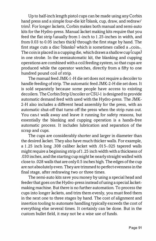
Page 91
Up to half-inch length pistol cups can be made using any Corbinhand press and a simple four-die kit (blank, cup, draw, and redraw/trim). For longer jackets, Corbin makes both manual and semi-autokits for the Hydro-press. Manual jacket making kits require that youfeed the flat strip (usually from 1-inch to 1.25-inches in width, andfrom 0.03 to 0.05 inches thick) through the first stage by hand. Thefirst stage cuts a disc (blanks) which is sometimes called a �coin�.The coin is placed in a cupping die, which draws a shallow cup (cups)in one stroke. In the semiautomatic kit, the blanking and cuppingoperations are combined with a coil feeding system, so that cups areproduced while the operator watches, directly from a fifty to onehundred pound coil of strip.
The manual feed JMK-1-H die set does not require a decoiler tohandle feeding of strip. The automatic feed JMK-2-H die set does. Itis sold separately because some people have access to existingdecoilers. The Corbin Strip Uncoiler or CSU-1 is designed to provideautomatic demand feed with used with the Hydro-press. The JMK-2-H also includes a different head assembly for the press, with anautomatic shut-off that turns off the press when the strip runs out.You can�t walk away and leave it running for safety reasons, butessentially the blanking and cupping operation is a hands-freeautomatic process. It includes lubrication and separation of thescrap and cups.
The cups are considerably shorter and larger in diameter thanthe desired jacket. They also have much thicker walls. For example,a 1.25 inch long .308 caliber jacket with .015-.025 tapered wallsmight require a beginning strip of 1.25 inch width with a thickness of.030 inches, and the starting cup might be nearly straight walled withclose to .028 walls that are only 0.5 inches high. The edges of the cupare not absolutely even. They are trimmed to perfect evenness in thefinal stage, after redrawing two or three times.
The semi-auto kits save you money by using a special head andfeeder that goes on the Hydro-press instead of using a special jacket-making machine. But there is no further automation. To process thecups into longer jackets, and trim them evenly, you must feed themin the next one to three stages by hand. The cost of alignment andinsertion tooling to automate handling typically exceeds the cost ofeverything else several times. It certainly can be done. But in thecustom bullet field, it may not be a wise use of funds.

Power Swaging, Page 92
Corbin's breakthrough designs have made it practical for verysmall businesses to produce high quality jackets with less than atenth of the investment normally required. The tooling is designedfor one specific jacket, but you can draw smaller calibers and shorterjackets using additional draw and trim dies. The final trim die isadjustable from the maximum design length to shorter lengths.
There are usually additional jackets that can be drawn from theinitial cup, or perhaps from one of the intermediate drawing stages,with other dies. Every additional jacket requires some developmentof tooling, and is limited by the volume of material present in theinitial cup. You can�t make a 50 caliber jacket by adding a fewdifferent dies to a set designed to produce .22 jackets, for instance.That much is probably obvious. But what may not be quite asobvious without some development work is whether you could geta .270 caliber jacket with 1-inch length by adding any dies to a setdesigned to make a half-inch long .50 pistol jacket. Maybe you could.I wouldn�t know until we had first worked out the feasibility (themath, on paper) and then tried building some prototypes (theresearch and development stage).
Often people ask me to quote the most economical package fora wide range of jackets, and they specify the lengths and wallthickness as well as caliber. Sometimes several calibers can be madefrom one basic jacket making kit by adding additional dies andpunches, but in order to use the same starting material and cuppingdies, only certain combinations of length, caliber, and wall thicknessmight be possible.
Any jacket you want can be drawn, as far as caliber, length, andwall thickness, but it might require a complete jacket maker kit anddifferent strip dimensions for some of them. There are some basicphysics that cannot be ignored, when it comes to the total volumeof material that can be obtained from a circle cut out of a given widthand thickness of strip. Normally, I will quote a price for a package ofdies that I know will work, even if later we find that some of the partsare not necessary. It is much more pleasant to inform a client that thepackage will cost less than expected than it is to disappoint themwhen a speculative, possible way to cut corners did not work.
Another method of making jackets involves tubing. Copper,brass, or even steel tubing can be obtained in slightly larger diameterthan required for the jacket. The first stage is to cut off pieces of thetubing, a job best done by a special tubing cutter saw. Corbin makes

Page 93
the SAW-1 power tubing saw to produce even, clean cuts on copperand brass tubing from 1/4-inch to 5/8-inch diameter, up to 3 inchlengths. You can also rig up a stop on your power bandsaw or tablesaw and purchase a fine tooth blade for it. The saws designed forcutting wood normally have the wrong blade speed for copper, butthey will work moderately well. Copper is a �sticky� metal thatshould be cut with a zero or even slightly negative rake tooth, withenough teeth per inch so that two of them are within the wallthickness of the tubing at any moment. Another method of cuttingcopper tubing to length is to use a turret lathe or screw machine. Thecut must be burr-free. The jacket weight will be controlled by theprecision of the cut.
The next stage rounds one end of the tubing. The die for this joblooks like a point forming die. It has a cavity shaped like a bluntbullet, and a small ejection pin at one end. A punch supports theinside of the jacket and has a shoulder that pushes on the oppositeend. The punch tip must be shorter than the jacket length to beformed, so the end can be rolled around. Generally, about half thediameter of unsupported tube projects beyond the punch tip. Eachlength of jacket you wish to make requires one �end rounding�punch. An alternative is the adjustable length punch, which costsabout three times as much to make as a solid punch. If you want twolengths of jacket, it is cheaper to get two solid punches. If you wantthree or more lengths, the adjustable punch makes good sense.
Pressing the tubing into the die rounds one end. It is then ejectedfrom the die, and pushed through a reducing die to bring it below thediameter required for the bullet. The tubing is then annealed, usingeither a propane torch or an electric furnace (heat the jacket red andlet it cool or quench in water to expedite the process�quenchinghas no effect on hardness, unlike tempering of steel). Using theregular core seating die for the desired caliber, a special punch goesinto the jacket. This punch is called the �end flattening� punch, andlooks like the end rounding punch, except that it is smaller indiameter and perhaps a bit longer. The end of the end flatteningpunch presses on the rounded bottom of the jacket and flattens itagainst the internal punch face.
If you wish to make a rebated boattail bullet jacket, the �endflattening� punch is replaced by one that looks more like the boattailitself. Instead of flattening the jacket end, it reshapes the jacket into

Power Swaging, Page 94
a boattail form. The die used with this punch is the BT-1 boattailforming die. It is the same die that will be used to seat the core intothe jacket.
Annealing is very important, since the tooling tolerances areclose and the amount of springback in the material strongly affectshow well the operations work. By annealing, a common point ofreference between the material used by the die-maker in developingthe set and the material used by the bullet maker is established. Withsome tubing, annealing may not be required. Tubing is interestingmaterial to work with, and can vary widely from different sources inregard to alloy, grain structure, hardness, tolerances for diameterand wall thickness.
Corbin supplies high quality tubing for which we have years ofdevelopment information. Using your sample tubing to develop aset of jacket making dies means developing the proper dimensionsall over again, and requires considerably more production time.Therefore, it costs less to order tubing with the dies, and then find alocal supplier later who can match the tubing specifications. If youwish to start with a readily available local supply of tubing, we willneed at least six feet of it (which can be sent in 2-foot pieces to reduceshipping cost) before we can start developing your dies and theinstructions for using them (which may be different from using ourstandard dies with our tubing).
Annealing the material helps prevent sticking, cracking, andwrinkling of the jacket. A normal anneal involves heating the jacketmaterial to cherry red, then quenching in cold water to knock off anyscale. At 1500 degrees (F.), the jacket is annealed very completely.Almost every problem that a person has with the proper coppertubing can be traced to failure to anneal the material. People justignore this because they don't want to stop and do it. Big mistake.
Soft coiled tubing is already annealed. It seems to work just fine,with the possible exception of cutting it to length (can't be done ina lathe, as the soft material flops around like a string). If the coils aretoo tight, then you may have problems getting the tubing to fit overa punch because of the curvature. Straight lengths of hard drawntubing are generally preferred to soft coiled tubing for mechanicalreasons.
Tubing jackets can be formed from material as light as 0.025-inch thick in the walls, to as heavy as 0.125-inch thickness. Naturally,it would be silly to try to form a small caliber with a jacket so thick

Page 95
that it left only a pinhole for a cavity, unless one wanted a solidcopper or brass bullet. Then, this is quite practical and works betterthan trying to use solid rod.
Tubing jackets can be formed with totally closed bases. Unlikethose formed in hand presses, the jackets made in the Hydro-presscan be gas-tight. The base thickness can be made several times thewall thickness, in fact. This is a function of the punch tip lengths usedin the end-rounding and end-flattening steps.
Selective thickening can be done, although the exact amountwill depend on material characteristics and is difficult to engineerbeforehand. A jacket with a heavier section through the lowerportion of the shank can be made by forming a normal jacket fromtubing, then using a short lead core to provide partial support to thelower shank. A steel punch that fits snugly in the remaining length ofthe jacket is used. The punch has a shoulder that presses against theend of the jacket.
Being supported firmly by the steel punch tip, the jacket will tendto collapse upon itself below the punch, where lead supports thewalls. If the lead provides enough support and the punch length iscorrect, the lower portion of the walls will thicken evenly. If anythingis out of balance, the lower portion may collapse by folding uponitself unevenly. But once the design is worked out, the particular setwill continue to produce good jackets so long as the material is notchanged.
Partitioned bullet jackets can be made by a similar method. Thetubing is cut to length, but it is made a little long (experimentallydetermined). Typically half a caliber extra length is allowed in mostmaterials. The material is drawn down first, before any end closureis attempted.
It is annealed, and put into a straight core seating die with twospecial punches. The two punches have tips that fit inside the jackettubing. They also have shoulders that fit closely to the die, and pressagainst the ends of the tubing. Because the tubing is supported by thepunch tips and is pressed on both ends by the shoulders, the onlyplace it can move is to buckle inward between the two punch tips.
This happens, and then the punch tips come down against thefold. Under tons of pressure, the fold becomes a solid partition witha hole in the middle, the diameter of which depends on materialthickness, caliber, and other characteristics. It is not practical toprecisely design the hole diameter given the number of variables,

Power Swaging, Page 96
but with 0.030 to 0.049 material in .30 to .375 calibers, it is possibleto make a small closure. In nearly all cases the partition will becomeabout twice as thick as the walls, and that alone is enough to stopexpansion and retain the rear core.
With brass and steel, the partition is an experimental thing thatmay or may not work in any given combination of caliber, thickness,and length. With copper, it is possible to insure it will work withnearly all calibers and combinations to some degree. The quality ofbullet that can be made this way is very high.
Copper tubing jackets can be thinned on the nose end for betterexpansion on light game, but there are some limits to the process.The most common way to handle this is to ream the inside of thetubing. If the reduction is from 0.125 to 0.035 or so, this is fine. Butif the reduction is from 0.035 to 0.020 or something of this nature,then the strength of the jacket wall to resist the torque produced bythe reamer not be sufficient. The torque produced by the reamermay destroy the jacket.
Also, the frail end of the jacket may not be sufficient to withstandthe pressures required to form the base. In that case, the jacket mustbe formed first at full wall thickness, and the finished jacket thenreamed part way to reduce walls. An easier way to do this would beto turn a taper on the outside of each jacket. When the core is seated,the internal pressure will push the jacket against the die walls andreverse the side on which the taper is formed.
In some cases it may be possible to produce a thinned frontregion on the jacket with a tapered punch in the core seating die. Thecopper tubing may be compressed against a tapered section ofpunch and extruded forward, thinning the walls. The tube may try tostick on the punch at this point, wedged against it under tons ofpressure, so that removing the jacket from the punch might requiregrasping it with smooth-jawed pliers and turning it. Or a custom builtextractor mechanism may be built to pull the jacket off the punch.Whether or not these measures are necessary depend on thegeometry desired in the taper and the material itself.
A final limit to jacket thinning operations is the force necessaryto push the jacket out of the point forming die. If the force requiredfor ejection exceeds the strength of the tip, the bullet will stick in thedie because the ejection pin will collapse the jacket or penetratethrough the tip. These factors limit the usefulness of thinning jacket

Page 97
materials to increase expansion. Done with care and experimenta-tion, the process can be perfected for a given caliber and style ofbullet within those limitations.
On the top panel of the Hydro-press, you will find a speedcontrol. This adjustment lets you set the ram travel from clock-likemovement to a maximum of about two inches per second. Whendrawing jackets, it is usually better to push them through quickly toavoid rapid stick and release action that causes rings or uneven wallthickness along the length. But during setup of drawing and, for thatmatter, almost any other operation, using the speed control to slowthe operation to a slow-motion demonstration can save time andparts. Slow motion of the ram lets you make sure of alignment.
Draw punches fit into the ram of the press, unlike external swagepunches, which fit into the floating punch holder in the press head.The FPH-1-H punch holder fits into the 1.5-inch by 12 TPI head ofthe press for swaging operations, but for drawing, the punch holderis unscrewed and the draw die takes its place.
A draw die for the Hydro-press can be made differently fromthose used in hand press. Because of the long stroke and full power,the Hydro-press die can have a long guide section, a reducing orifice,and an after-guide section to maintain straitness. Most materials willtend to curve to one side or the other as they are drawn, followingthe slightest weakness in the material wall. With the carefully hand-lapped guide sections, jackets may be drawn very precisely withoutthe bending, and with greater concentricity.
The design of bullet jackets is greatly simplified with a softwareprogram called DC-CUPS. This program has four main parts. First,it lets you calculate the material requirements and costs for makingdrawn jackets for virtually any shape and caliber of bullet. Second,it has the same capabilities for tubing jackets. You can determine thejacket length, cost, weight, how many feet or pounds of tubing youneed for a given quantity of jackets, and work backward from almostany of these figures to get the others.
The program has the ability to store your jacket information andassign catalog numbers to them associated with the bullets youmake (commercially), so you can keep a ready database of informa-tion as you learn what is needed for given bullets. And fourth, it hasa math section that can calculate instant answers for complexvolume, weight, and trig problems involved in jacket and bulletdesign.

Power Swaging, Page 98
Jacket-making die sets are always provided with matchingpunches. It is necessary to make the punch with the die for testing.The cost required to produce dies and punches is primarily in testingand adjusting dimensions to work with a given sample of tubing, notin the material from which the dies are made. Whether or not thepunch was provided, the cost involved would be nearly identical.
I only mention this because on one or two occasions, someonehas taken me to task for not offering part of a die set for a lower price.The rationale has usually been that since the person already hadsomething that might work, they didn�t want to buy another part likeit. In some products that would be sensible. After all, if you only needa new fan belt, there is no point buying the whole engine to get it.
On the other hand, if you were having a new engine built, itwouldn�t save you anything to tell the builders you already had thepiston rings, so leave them out. In order to test and make sure thething works, they have to install the rings and then afterward, spendmore time removing them for you! It actually costs more, in somecases, to build something and not supply a part that is required fortesting.
For example, if you want the empty frame for a four cavity coremould, it would seem logical that this ought to cost less than thecomplete mould. But we build the moulds in matching parts sets, justenough frame parts to go with the number of cylinders and pistons,because almost no one ever wants just the frame. Part of theoperation is in machining the top of the mould with cylindersinserted so that the assembly is perfectly flat, preventing leakage ofhot lead.
In order to supply an empty frame, we have to take apart acompleted mould, which is twice as much work as just shipping thewhole tool! Labor costs far more than material. If we had plenty oflead time, and could keep track of it well enough, we could schedulethe production of one extra frame on the next production run. Butkeeping track of the special order, getting the information to thevarious die-makers and machinists at the right time, and makingsure that the special job is set aside for a single order without anyonemissing their cue and forgetting to step around the well-establishedprocedures, can take considerable planning and logistical time,which someone must be paid to do.

Page 99
As a result, a special order for a part that normally isn�t made forreplacement sales can cost more than just the production labor andparts would indicate. This is also the reason why replacement partsfor some machine tools can seem vastly overpriced, and yet afterstudying the reason for the price, it makes good sense and isnecessary in order to keep a handful of obsolete machine compo-nents available for years, taking up storage space as well as trackingand handling time.
I needed a replacement gear for a large but �obsolete� model ofmilling machine. It cost about half what the machine cost when itwas new! My first inclination was to think I was being gouged. Butafter thinking about it, I realized that the machine tool people hadpaid to make and keep this part on hand for twenty years, keepingrecords of its location and paying for the storage space throughmany moves and changes, through conversion of their records tovarious computer systems. They were able to put it in my hands twodecades later with just a phone call.
The cost of the gear was not what it cost to make. It was what itcost to make plus all the effort that had been expended making sureit would be there when I needed it. (Being a parsimonious soul, I hadone of my die-makers build one instead, but after studying the timeit took and the value of dies that were not made during that period,I decided it would have been wiser to just pay for the �overpriced�part and be done with it. Thinking like a person whose time is�hobby� valued is an expensive mistake for a person whose time ismarket valued.)
With custom shapes and materials for jackets or bullets, we aretalking about developing handmade tools to do a specific job, notreaching in a bin and grabbing one of thousands of identical parts.Even a thousand dollar die set probably doesn�t have ten dollarsworth of steel in it. The value is in the effort and hard-earnedknowledge applied to assure that the die set will work properly witha given job. A manuscript for a bestselling novel is worth more thanthe two dollars for the paper and ink that contain it. When you havea set of dies built for a specific job rather than choosing a set off theshelf, you are in effect commissioning the manuscript.
When you buy the press, on the other hand, you are buying acopy of the manuscript, because the development and design hasbeen done previously. Instead of hiring a team of die-makers andmachinists and designers to come up with a new press, you are

Power Swaging, Page 100
paying a much lower amount for the parts, labor and skill requiredto assemble one that has been tested and proven many times over.Each standard product that we develop may have years of work inits design and testing, tens of thousands of dollars already investedin jigs, tooling, experiments that failed but pointed out ways to solveproblems, and eventually resulted in the dimensions and tolerances,material specifications and techniques needed to duplicate thedesign and be certain it will work every time.
When you select a standard design for jacket drawing, usingmaterial that we provide initially, then you benefit from the work andmoney already spent on years of previous models and versions.When you select a new material or design, at least some of that workhas to be done for you alone. The difference in cost is a directreflection of that additional work. It is not arbitrary. We used tospend more solving unexpected problems with client-supplied ma-terials or nonstandard designs than we quoted, and sometimes westill do. Naturally, if we�re going to be around next time you needsomething special, it is in everyone�s best interest that the priceactually cover the cost of doing the work. Otherwise the die-makerswill soon be back working for Lockheed or Hughes Aircraft, prob-ably making more than they do in the firearms business (but perhapsgetting less enjoyment from it).
A fellow wanted to buy a building site, and he asked the realestate agent how much it cost. The agent said it cost $50,000. Whenhe asked why it was so high, the agent said it had a great view. If thefellow had asked how much it was without the view, you�d have apretty good idea of the situation when someone asks me how mucha die set is without one or more of parts I have to make in order to buildand test that set.
I�m always tempted to finish that story by saying that the agentthought a minute, and said �Without the view, it�s only $10,000.� Theprospective buyer said, �Fine, I�ll take it,� and wrote a check,whereupon the agent asked �Now, where do you want it delivered?�
But I won�t.

Page 101
Power Bullet Swaging
In writing this book, I am assuming that you are already familiarwith bullet swaging, or that you have purchased one of the morebasic swaging books such as Rediscover Swaging or The CorbinHandbook of Bullet Swaging. That is why you won�t find a detaileddescription of bullet swaging technique, tooling, and examples ofexotic bullet designs in this book. They are readily available in theothers.
On the other hand, there are some operations that cannot bedone at all on hand presses, and most of the information in the otherswaging books assumes you will be using a hand press.
Also, there are both position and pressure controls on theHydro-press. Some operations work best by stopping at a givenpressure. Others work best when you stop at a certain position. I�llsuggest the best combinations in this chapter.
The first operation in swaging a bullet is to produce the core. Thelead filling or core of the bullet can be cut from lead wire or cast fromscrap lead in a core mold. There is no particular problem with eitherone: some people like the convenience and speed and safety of usinglead wire, others find the savings of using scrap lead worth the fumesand fuss of casting.
As for the end results, once you have passed the core through acore swage die, you can�t tell any difference. With casing you cancontrol the alloy. With lead wire, you have pure lead to work with.Using the Hydro-press, you can extrude lead wire with the optionalLED-1 extruder kit. The lead can be purchased in round billets, fromCorbin or other suppliers, or it can be cast with the tube moldsprovided in the kit.
You cannot extrude hard lead with this kit. But you can produceexcellent, chrome-like lead wire from soft lead, and do it quicklyenough to be profitable. You can even extrude hollow tubing withoptional mould and extrusion punch components. However you doit, the cores need to be cut to length (if made from wire) and thenswaged to precise weight and shape. Cast cores are typically cast todesired length, so you do not need to cut them. Some people havesuggested that we make a very long mould so the cast cores can be

Power Swaging, Page 102
cut to length, but with some consideration it becomes evident thatcasting them to length with an adjustable mould makes far moresense than both casting and cutting the same cores.
Making a swaged lead bullet without a jacket (but it can be witha gas check or Base Guardtm disk if desired) can be done in a die thatfor all practical purposes is identical to a core swage. This die is theLead Semi-Wadcutter or LSWC die. We call it �semi-wadcutter�because any bullet it makes will have either a 90-degree shoulder ofat least .015-inch width before any nose or base protrusion takesplace. Don�t take this designation to mean some specific nose shape.It is a generic term that can be used with round nose, truncatedconical nose, flat nose, bevel base, boattail base, hollow base, hollowpoint...you get it, right? The actual shape of nose or base after thatlittle step can be whatever you want.
The reason this simple, one-step bullet making die must producea small semi-wadcutter or SWC shoulder, regardless of the endshape, is that the die has a straight cylinder cavity fitted with twopunches, and the shape of the bullet is a mirror image of the punchend. If you attempt to machine a cavity that comes to a feather edge,attempting for example to make a round nose bullet without anyshoulder, the pressure applied to the inside of that cavity will beenough to shove the thin metal edge firmly against the die wall, andthen rip off the paper-thin steel leaving a thickness of about 0.015 atthe ragged edge of the punch.
So, rather than let the pressure create a rough edge, we machinethe punch with a nice, even .015 thick edge. That is the rightminimum thickness to withstand internal swaging pressures of15,000 psi or so. If you try to use harder lead, and raise the pressureby doing so, or if you try to swage too rapidly, the pressure willexceed the tensile strength of the punch edge and give you a ragged.020 thick edge instead! To avoid that, we can design the punchesused with harder materials and faster strokes with a thicker edge.
Both the core swage die (CSW-1-H) and the lead semi-wadcutterdie (LSWC-1-H) are built in the same pattern. The die is a 1.5-inchdiameter cylinder about 2.5 inches long with a hole preciselythrough the axis, and a reduced diameter shank with 1 inch by 12turn per inch threads (1.0-12 tpi). The bore of this die is honed to afine finish and exact diameter, and equipped with hand-fitted puncheswhich are honed to exactly match with a sliding fit.

Page 103
One punch fits inside the die, and has a portion that is the samelength as the die, then a large �head� section. This punch fits into thethreaded end of the die. The punch head rests on a shoulder withinthe press ram when the ram is raised. This holds the working end ofthe punch at an exact distance inside the die, above the threadedshank portion, in the large diameter section, when the ram is up. Asthe ram comes down, there is a hard steel bar through a slot in theram, which eventually contacts the punch head and lifts it off theshoulder. As the ram continues down, the knockout bar comes to astop against the large base plate of the press head. The ram and diecontinue down, but the internal punch is stopped by the knockoutbar. At some point, the internal punch head will come up against thethreaded end of the die, which means the working end of the punchis at the die mouth, and anything in the die is pushed out (ejected).
Usually, the end of the internal punch forms the base of the leadbullet. It does not have to, but keeping the internal punches primarilyas base punches makes it easier to order different nose and baseshapes since we can assume that the punch for a base is the long,internal punch unless otherwise specified. The nose is formedagainst the end of the external punch, which has a short head, a bodysection, and the working tip section that fits into the die mouth. Theexternal punch is held in the press head by the floating punch holder.It is adjusted up and down to control how far the punch reaches intothe die, and thus how much volume is left between the internal andthe external punch tips when the ram is raised to the top position.
In either the CSW-1-H or LSWC-1-H die, the bullet weight isadjusted by extruding a small amount of lead from the core, throughbleed holes in the circumference of the die. The standard design ofdie uses three identical bleed holes spaced at 120-degrees, justabove the top of the internal punch tip when the ram is fully raised.(You can see that the distance from the top of the ram to the shoulderwithin the ram is critical, because it controls how far back theinternal punch can drop, which determines the distance from thepunch face to the mouth of the die. This distance is the maximumpossible volume of material that will fit into the die, and is somewhatmore than the maximum you can actually use to make a bullet sinceyou must allow at least a full caliber of free movement for theexternal punch to align with the die.)

Power Swaging, Page 104
To adjust the weight of the bullet, first make your core slightlyheavier than the bullet you desire. Anything from five to twenty-fivegrains more weight will do. The die cannot add any weight to thecore, so if the tolerance or variation in core weight is greater than thedifference between the nominal core weight and the desired bulletweight, you will have some lighter bullets. To determine the mini-mum surplus allowance, weight ten cores that you have cut or castbut not yet swaged. Add the total weight for all ten, and then divideby ten to get the average. Subtract the lightest core weight from thisaverage weight. This is the minus variation. If you want to know theplus variation, subtract the average weight from the heaviest coreweight.
Say your average weight is 160 grains and your minus variationis 5 grains. That means you can just get away with making a 155 grainbullet using those cores, but it would be safer to double the variationand make nothing heavier than a 150 grain bullet. That would leave5 grains minimum bleed-off on all the bullets, insuring some resis-tance and pressure will be developed for all the bullets.
The rule of thumb is to find the minus variation, double it, andsubtract from the average weight, and use this as the heaviest weightbullet for those cores. Of course, if you are starting to make the cores,you can just make them 5 or 6 percent heavier than the heaviestbullet you expect to swage, because the variation typically will notbe more than 3 percent plus or minus. On a 50 grain bullet, 3 percentis 1.5 grains either way. On a 500 grain bullet, it is 15 grains eitherway. (Precision weight control is a percentage value of the totalbullet weight, also, because it is the percentage and not somespecific grains that makes the difference in bullet flight.)
Since forming a SWC type bullet and forming a core use thesame procedure and settings, I�ll just talk about swaging the core.You can apply it to making lead bullets in the LSWC-1-H die also.
Swaging the core cannot be done with the pressure reversingmethod. That is, you cannot set the pressure sensor to reverse theram at a given level and come up with consistent cores. Why not?
First, consider the way a core swage works: the pressure buildsup inside the die between two flat punch faces, until the lead fills thedie space and begins to extrude through three bleed holes in the sideof the die. Until this happens, the pressure is low and rises more or

Page 105
less in a linear way. When the cavity is filled with lead, the pressurerises suddenly, then changes rate as the lead begins to move throughthe bleed holes.
Increasing the pressure only increases the rate at which the leadspurts out. If you select any given pressure below the extrusionpoint, you will never change the weight of the core. Heavy cores willstill be heavy, light ones still light. Once extrusion starts, it maintainsa constant pressure for a given ram speed. That means, if you set thepressure to reverse at a given point above the minimum extrusionpoint, you�ll only succeed in moving all the lead out of the die, or atleast enough so that bleed holes are finally blocked by the incomingpunch (which leaves the minimum possible core weight in the die).
Setting the pressure reversing mechanism to reverse the ramwhen the extrusion pressure is reached will only succeed in juststarting an extrusion before it is stopped. That won�t accomplishanything in regard to weight control.
The way to insure accurate weights is to set a fixed volumebetween the two punches. That is, you must swage cores bystopping at a given position each time. And that position must besuch that the lightest core you put into the die still has greater lengththan the length between the final resting point of the two punches.Otherwise, some cores would not be adjusted at all and otherswould. Light cores would still carry their variations.
For core swaging, the pressure reversing mechanism is onlyused as a safety backup, or turned off. Set the pressure higher thanthe minimum required to move the lead. Then stop the ram at a givenposition, not a given pressure. If you wish, set the reversing pressureswitch on and adjust the auto pressure control so it won�t trip unlesssomething goes wrong and the ram overshoots the top sensor (notlikely).
I have noted before that you must have the pressure high enoughso the lead comes out fast. If you set the system pressure so low thatthe ram can be stalled, or nearly stalled, you will get variations evenif the position is controlling automatic reversal. Lead flows ratherslowly, and continues to move while under any pressure. There willbe differences in core weight determined by the length of time youhold the pressure and how fast you apply it. Use more than theminimum pressure required to flow the lead, and hold it for at leasta few milliseconds by setting the top dwell timer.

Power Swaging, Page 106
If you have trouble with core weight variations, increase thepressure and the dwell time. If you still have trouble, check for loosecomponents such as the nuts that hold the top plate on the guiderods, and coupling between the cylinder rod and the press ram, andwatch for any side movement of the press head under swagingpressure. If you detect any noticeable movement of press head, usea torque wrench to apply even torque to both top nuts, and check thebottom nuts too.
But more likely than any of this is the misuse of the settings.Make sure that the position sensor is, in fact, controlling the stoppingpoint. Switch off the pressure switch and try it. Move the top sensordown an inch and readjust the punch holder to match, to make sureyou are not sitting at the end of the cylinder stroke.
If the cylinder top limit is reached, and the pressure reversingswitch is on, then it is possible that reversal of the ram is beinghandled by the combination of the physical limit of travel (whichnormally just stalls the ram) and the rise in pressure at that point(which trips the pressure reverse mechanism).
The position of the ram can vary slightly because of inertia andtemperature variations in the hydraulic system, slight differences invalve closure timing, and trip tolerances in the position sensor.Normally, the combined effect is not enough to be of concern. Butbullet makers include perfectionists. Marketing of custom bulletsinvolves the psychology of the buyer, who has only two precisioninstruments with which to test the bullets (other than�heavenforbid!�judging them on the size of the group they make in thetarget): the micrometer to check diameters, and the powder scale tocheck the weight.
There is an old saying to the effect that when your only tool is ahammer, every problem begins to look like a nail. This has neverbeen more true of the target shooter who judges the potentialaccuracy of a bullet by the one thing he is sure he can measureaccurately, the weight. Weight variation in the bullet is blown far outof proportion both figuratively and mathematically in regard to itseffect on where the bullet will land. The average handloader prob-ably does not grasp the difference between percentage of variationand numerical measurement of variation. The percentage of varia-tion is what counts.

Page 107
An easy way to illustrate this is to consider a .224 benchrestbullet and a cruise missile. The .224 bullet probably weighs from 50to 60 grains. Let�s call it 50 grains. The cruise missile probablyweighs about a thousand pounds, with warhead. That would beabout 7 million grains, since there are 7,000 grains per pound. Thedecal that says �US Navy� might weigh about 25 grains. Assumingthe missile lost direct guidance control and went into a stableballistic glide toward the target, how much difference do yousuppose it would make in where the missile landed if someone forgotto put the decal on it?
With a stable, balanced airframe the difference would be in theeffect of gravity pulling on the difference between 7,000,000 grains,and 7,000,025 grains. The variation in weight is about 0.0004percent. The difference gravity will make on the point of impact isso ridiculously small that no one would even give it a secondthought. The variation in gravity itself from the influence of heavenlybodies or maybe even an aircraft flying overhead would be in thesame ballpark.
Now what about the same 25 grain variation on the .224 bullet?Wow, that is half the weight or 50 percent variation. You betterbelieve that will affect where the 50 grain bullet will drop (assumingthe gun holds together when it fires a 75 grain bullet with the loadexpected of a 50 grainer).
Weight variation is important in its relation to total bullet weight.Stating a certain grain variation without mentioning the bulletweight is giving half a comparison. It is a standard advertisinggimmick, but anyone who listens with more than half a brainunfurled scoffs at such statements as �this gun is 20% more accu-rate�. Most of us just smile and say to ourselves the other half of thecomparison, �...than what? A slingshot?�. Yet when it comes tobullet weight variation, there is a universal tendency to clucktongues and shake heads when we hear of bullets that vary by threegrains or ten grains. Vary from what? A 900 grain 50 BMG slug? A20 grain .17 caliber bullet?
In an attempt to quantify at least approximately how muchvariation, as a percentage, is acceptable in an accurate bullet, overthe years I�ve done variations on this test so many times that I�velong ago lost count: swage two piles of identical bullets, with theexception of core weight. Make one pile as precisely close to a givenweight as I can, and make the other pile just as precisely a different
Power Swaging, Page 108
weight. Shoot groups with both piles of bullets and note the groupsize. Then mix the rest of the piles together and shoot more groups,and see how much they open up.
To minimize the human factor, I frequently used a machine restwith a barreled action mounted on an inertial slide, and fired therounds with a camera shutter release attached to the trigger. I alsoexperimented with known amounts of imbalance, by putting a nylonstring of known weight on the side of the core to unbalance it. Usingdifferent diameters of weed-cutting string and fishing line, I couldapply more or less imbalance by percentage of weight. This let mecompare concentric weight variation with eccentric variation.
To make a very long story shorter, group sizes were consistentlylarger when the concentric weight variation exceeded about twopercent of total bullet weight. The average variation was veryslightly larger but started to disappear into normal shot to shotvariations with a one percent (plus or minus) variation, regardless ofcaliber or weight. When the variation was held to half a percentage,I could detect no difference whatever between shooting the mixedpiles and all of one pile, using machine rests in windless conditions,better than benchrest conditions in most instances.
With eccentric (string down the side) variations of the samemagnitude, the story was different. Groups would be as much asdoubled by two percent variations, and noticeable out of the back-ground fog statistics for normal groups even at half a percent. Theywere still as good as most factory bullets, but not as good as the bestbullets I could make by hand testing each one.
The thing that stood out most to me was the size of the rawnumbers compared to the percentages. When I was shooting my.222 Remington barreled action, with 52 grain bullets, a 1 percentvariation was plus or minus about half a grain (0.52 grains) Mypowder scale instruction booklet said it was only accurate to 1percent of full scale reading. That meant with 100 grains full scale,it was only capable of giving me plus or minus 1 grain. If this bookletfrom the manufacturer were to be believed, the scale really couldn�ttell me that the 52.5 grain bullet was exactly that any closer thanfrom 53.5 to 51.5 grains, or plus or minus 1 grain. Yet here I was,believing the scale to be the last word in precision and worryingabout the variation in bullets.

Page 109
Of course, the absolute accuracy of the scale wasn�t as importantas its repeatability. Maybe it was off by anything up to one graineither way, but it repeated the lie consistently and I couldn�t find anyjustification to convict it of perjury. I was unable to locate any factoryspecification for repeatability on this or any of my other scales, justthe accuracy figure. Most scales were only specified at from 1 to 3percent of full scale reading, and most of them had a 250 grain fullscale reading, so you can do the math!
Using analytical balance weights from a scientific equipmentsupplier, I checked the scales and found that they were well withinthe stated accuracy, although certainly not as precise as the expen-sive little weights. Converting the grams in to grains, I found thatmost of my scales read from half a grain to a grain and a half �off� onedirection or the other from the plus or minus half percent weights inthe 50 to 150 grain range. So much for the doctrine of scaleinfallibility, but hooray for the honesty of the specifications.
The moral is, figure percentage of variation as your standard forquality, not absolute weight variation. Holding better than 2% willmake a good hunting bullet. Holding better than 1% will make a finetarget bullet. If you manage to hit half a percent, plus or minus, youare in the zone of diminishing returns and need do no more even forbenchrest shooting. In grains, this would mean a 50 grain bulletcould be world class in every way and still have a variation of plusor minus 0.25 grains. A 168 grain bullet would need to maintain 0.84grains plus or minus to meet the same standard. And a 450 grainbullet would be in the league of champions with a variation of plusor minus 2.25 grains.
Adding and subtracting these differences makes the point evenmore clearly: a good benchrest 50 grain bullet could weigh from49.75 to 50.25 grains. The 168 grain nominal weight box of bulletscould contain individual bullets that weigh from 167.16 grains to168.84 grains, and the box of 450 grain bullets would be just asprecise in weight control if the ranged from 447.75 to 452.25 grains.My guess is that the gut reaction most handloaders have, when theyread that a benchrest bullet can have plus or minus half a percentweight variance, is to automatically translate that into plus or minushalf a grain. Try to resist that temptation, because it makes you spinyour wheels trying to hold far more tightly controlled weights thanwill have any practical effect.
Power Swaging, Page 110
Having said all this, let me go back to method of achieving tighterweight control. Since the electronic system is limited by the drift ofthe cylinder once oil is shut off, a way to overcome even thisvariation is to mechanically block the progress of the ram relative tothe external punch, and then adjust the amount that the punch canreach into the die. The FPH-2-H positive stop punch holder can beused to do this job. It replaces the standard punch holder with ahardened, tempered unit capable of withstanding the full thrust ofthe press. Instead of holding the external punch in one position, itallows the punch to move up until the punch comes to rest againstan adjustable stop.
This means you can run the die face against the end of the punchholder safely, and adjust the distance that the external punchreaches into the die cavity to set the weight of the core exactly. Theram cannot continue to drift upward once the die contacts the punchholder, so the distance between the internal and external punches isabsolute and fixed, once you adjust it. But you need to change onething. The mechanism for reversing the ram by position won�t worknow.
If you set the top sensor below the contact position of the punchholder and die face, you still have some drift between the sensordetecting the position of the ram, and the contact position. If you setthe top sensor higher than the contact position, it will never turn onand the ram will just sit there, pushing forever until you manuallypress the �down� button.
Ah, but if you set it exactly at the right point, where the die andpunch holder meet? Won�t that work? Sorry, but it will only workintermittently because of the slight drift in position created by thehydraulics. Sometimes it will trip exactly right, but other times it willmiss just enough to stop too soon or maybe not stop at all (in whichcase the punch holder and die face contact just holds the press in astall).
The answer is to switch on the pressure reversing toggle switch,and set the pressure reversing level a little lower than the drivepressure, then move the top position sensor a little higher than thedie face and punch holder contact position. Now, as soon as the diecontacts the punch holder, system pressure will immediately headfor the drive limit, but just before it gets there the pressure reversingtransducer will switch on and initiate the dwell timer for the downstroke.
Page 111
Yes, we are using pressure to reverse the ram during a coreswaging operation, but actually, we are using a positive position stopto set the weight control and then bringing the pressure into itwithout any affect on upward ram movement. This is the ultimateweight control situation, capable of making bullets with weighttolerances below the rating of almost any handloader powder scale.
Core seating, on the other hand, can be accomplished moreaccurately by pressure reversal of the ram than by position. Supposeyou do have slightly thicker or thinner jacket bases. If the jacketsweigh the same, and the cores are accurately made, then quite likelyyour bullets will all be winners even with some slight variation inoverall thickness or base variation.
If the walls are thick on one side and thin on the other, forget it.Those are not winners. (They might be fine for hunting bullets,depending on the range and the amount of wall thickness run-out.)Merely having some jackets with thinner or thicker walls by itself isnothing to worry about. If you seat the same core in a thicker jacket,it will typically stop closer to the jacket mouth, make a bigger leadtip on a lead tip bullet, and of course generate more pressure at thesame position of punches during core seating. If the difference ismore than a thousandth or so in thickness, the same diameter punchmay leak lead around it with thinner jackets and tend to wrinkle orplow up jacket material in the thicker ones.
If you seat the same core in a thinner jacket it will generate lesspressure at the same punch insertion depth. It will make a smallerlead tip or a little deeper core in an open tip. That is, it would if youused pressure rather than position as a criteria to stop pushing.
When you push to a certain distance between two punches andstop, you are assuming everything is perfect in regard to the jacketand core. If it is, you will get good bullets. If not, you will probablyget bullets seated with a huge variation in pressure. This variation inpressure will do more damage to accuracy than the variation injacket thickness ever thought about. Pressure translates to bulletdiameter. It translates to the amount of base diameter or pressurering when the point form and core seat die are not extremely closein diameter.
If you use pressure as a criteria to determine where to quitpressing, then each core will be seated to exactly the same pressureeven if the jacket thickness does vary. The same pressure willtranslate to the same diameter, the same base expansion, and the

Power Swaging, Page 112
same hole in the target. We are talking about small differences injacket thickness here, not major ones. You always have somevariation in everything. It is just a matter of proportion.
In core seating, set the system pressure to the point where youget a good consistent core and jacket diameter. Then set the autopressure reversing to kick in just at that point. Finally, with thepressure transducer in control, raise the system pressure limit a little(100 psi) above that point so there is no chance of NOT reaching thetrip point. And then, move the position sensor just above the placewhere it would normally take control from the pressure transducer,as a backup in case you put an empty jacket or light core into the die.
With point forming, some people get better results by reversingat a certain pressure. Others get good results with the position.Consistent pressure has more to do with the ultimate bullet diameterand taper, while consistent position has more to do with the degreeof tip closure and overall bullet length.
The results depend to some degree on the consistency of thejacket. Harder or softer jacket material will translate into differencesin both the length of the bullet and in the evenness and size of the tip.The smallest jacket tip diameter (meplat) is the diameter of theejection pin hole, because the jacket material will simply follow thehole if you keep pushing the bullet further into the die.
Normally, the pressure that you use for forming a point with aconventional wall thickness and jacket material will be fairly low.Pressures of 200 to 300 psi on the Hydro-press gage are common(some thick, heavy jackets and extreme ogive shapes take morepressure). In most cases, the highest pressures are encountered informing copper tubing jackets, in the end flattening or boattailforming stage. Core swaging pressure depends on the materialresistance to flow, which with lead cores is related to hardness of thealloy.
Most soft lead cores use only a few hundred psi on the gage. Coreseating depends on the jacket, base shape, and core hardness.Always start with a very low setting and work up until the jacketshows signs of expanding to the same diameter as a lead slug formedin the same die without a jacket. Stop increasing pressure as soon asyou reach this point, because any more force only stresses the die.

Page 113
With lead tip forming, you will probably have to use positionbecause the pressure required is so low that there isn�t much controlleft. That works out OK, since the tip shape is more a function of howfar the punch is pushed down against the bullet than how muchpressure is used.
Other swaging operations, such as forming a rebated boattail(which involves seating the core in two separate dies, first formingan angle and then shaping a rebate or step from the pressure of thelead forcing the jacket into conformity with the die), can be doneeither by position or pressure reversing. Generally it is easier to useposition.
Of course, any operation can also be done by turning off bothpressure and position switches, and simply letting the top sensorstop the ram. The UP and DOWN buttons manually control the rammovement. What is lost is the consistent timing that the automaticreversing logic provides.
In a few situations, it has been found that bumping the compo-nents two or three times produces a more perfectly formed projec-tile. This can be done by turning the dwell time to minimum and�jogging� the ram up and down at the top of the stroke. Using theAUTO mode works very well. If the ram is still going up when youpress the DOWN button, it will reverse, then go up again by itselfwhen you release the button.
My own favorite way of operating the press is to use a singlestroke, AUTO mode. This involves turning the press to AUTO, andturning on the LOAD POS. switch. The component is placed in thedie, which is initially raised to the loading position (just an inch or soabove the bottom position).
The purpose of the loading position is to retract the internalpunch enough to put another component in the die. Otherwise, if youstop at the bottom, the internal punch is raised to the mouth of thedie (to eject). There is no convenient way to load in another part. Youwould have to sit the components carefully on the punch and hopethey stayed while you pressed both buttons. Or you could raise theram by pressing the UP button again and releasing it after the ramstarts up.
With the loading position set up, you don�t need to have yourhands anywhere near the die when it is moving. The slight retractionof the internal punch gives you room to push the components partway into the die mouth, where they will be held. As long as you are

Power Swaging, Page 114
reasonably careful about lining up the top punch (which, for the mostpart, is automatic since the punch hangs straight down and themouth of the die is beveled to guide it and the components), thepunch and die will go together nicely on each stroke.
The older models of the CHP-1 had mechanical switches withroller arms to sense the ram position. These units needed room towork, and limited how closely you could set the loading and bottom(as well as top) positions. The electronic proximity sensors, on theother hand, have a center to center distance of only 3/4-inch.Adding another half inch for the locking nuts still gives you about aninch and a quarter minimum spacing, which is fine. The current CSP-2H Hydro Junior does not use a center or loading position sensor,so it can utilize two roller ram limit switches without crowding eachother. This also simplifies the electronics, since each electronicproximity detector requires a slave relay to handle the switchinglogic, whereas the double throw roller limit switches can handle thecurrent without relays.Setting up the bottom sensor with any die (tht has an internal punch) consists of installing the die in the ram, nd running the ram down with minimum system pressure. When theram stops, check three things:
1. Is the ram stalled against the punch head or did the bottomsensor light come on, indicating that the sensor stopped thepress?
2. Is the punch pushed far enough toward the die mouth so you canget the component out of the die easily?
3. Is the big spring around the ram coil-bound or crushed, or is therestill space between the coils as there should be?
In a few cases, such as with the forming of partitioned jacketsand deep cup base bullets or heel-type bullets, you may want toadjust the bottom sensor so that the internal punch is just trapped bypressing against the ram and knockout bar as the bottom limit isreached. In this way, the punch will be held steady, locked againstturning in the die. You can use a twisting motion, or even a soft-jawpliers, to pull the part off the punch if it wants to stick.
When you receive a set of swaging dies, the instructions thatcome with them will indicate if there is any special mode of opera-tion about which you need to be aware. The dies have been testedand have made bullets. Due to customs and border inspections, wemay not always be able to include sample bullets with the dies (diesare just metal-forming tools, but people who don�t understand

Page 115
shooting sports can go ballistic (no pun intended) about finding asample bullet in the package. But rest assured, the dies were used tomake some bullets before they were shipped. That is the only waywe can find out if they work correctly or not.
A caution to observe is never to put anything into a swage dielarger than its bore. It seems obvious, but let me repeat: swaging isthe process of expanding a component to meet the die walls.Drawing is the process of reducing a component to a smaller size byforcing it through an open ring die. You never swage down, just likeyou never draw up. At least, if you value your dies, you don�t.
From time to time, I�ll get a point forming die with a piece ofcopper or brass rod jammed tightly into it, along with a brokenejection pin. The bottom of the rod will be 7/16" diameter or more,and the bore of the die will be .429 or less. Just an example: youcan�t expect a .437" rod to somehow gently release itself from a .429"diameter hole after you force it in under tons of pressure.
�I was just trying to swage it down,� the note will say. Well,swaging doesn�t go that direction. Drawing does. The dies aredifferent. A drawing die is open on both ends and you can pushthe component all the way through it.
Just as often, I�ll get back a punch that is either broken orseverely scored and reduced in diameter with a note that says itdidn�t fit into the die. No, most likely it didn�t, since it was made forthe point forming die, which has a .308" diameter, and the unfortu-nate die that got the dubious honor of receiving the punch for aonetime visit happened to be a .3070" diameter rebated boattail pre-former. The easy prevention of this particular destruction is to tryany punch into a die by hand. If it won�t go, seems likely it might notbe made for that die. Then, if all else fails, look at the markings on thedie and on the punch. Punches have a code letter that indicates thetype of die they fit, and a diameter or caliber indicated.
If you don�t understand how to set up the dies, or if you have anytrouble making the bullet, the first thing to do is contact us anddescribe the problem or ask how to get started. Don�t assume thatthe dies are �bad� if the bullet comes out undersized or you can�tseem to get the results desired. Anything is possible, and if the diesare defective they will be replaced, but it is extremely rare. The mostcommon problem is just that our instructions may not have beenclear enough.

Power Swaging, Page 116
Maybe we didn�t get it across that following the procedure reallywas important. Perhaps we didn�t state clearly that the tubing jacketwall thickness or diameter tolerance needed to be within a certainrange. Or, heaven forbid, maybe we sent you the wrong punch forthe length of jacket or size of core that you intended to use, becausewe made an assumption that you were using something else.
All these things are easy to fix. Usually the hardest part is thecommunication, understanding exactly what is being done wrong,and why. Sometimes the most frustrating problems have turned outto be nothing more than misunderstanding about how something isdone, or what steps absolutely must be done in the right sequence.Sometimes they have been merely using a longer or shorter core, tomake a different weight of bullet, with tooling that was tested andworked fine with some other length or weight range just outside ofthe one now desired.
Samples are always helpful. Send both samples of the compo-nents being formed, and samples of the bullet after it has beenformed (or at least, the result of the step that isn�t working asexpected). If you do return a die, it is helpful if you also include thepunches that are being used in the particular step in question, andsome sample component parts just before they are used in this step.That way, we are using exactly the same material and punches asyou. It avoids those instances where the problem is in the part thatdid not get sent back!

Page 117
Power Swaging Business Tips
Over the years, we�ve made some very unusual punches to formfins, saw teeth, cross-splits, and a world of other odd designs for ourclients. Each of these unusual designs has its own special consider-ations in regard to how the press is set up and how much pressureto use. A big part of the work that is done for you by the die-makeris the experimentation and determination of a working processwhile the dies are being made.
If you draw up a bullet design and take it to a regular tool and dieshop, you may be able to get a set of tooling produced that will resultin the bullet you want. But few die shops will deliver the process aswell as the tools: in most cases, you will get a set of tools that matcheswhatever dimensions and tolerances YOU specified on the draw-ings YOU made. The die shop will present you with a bill, hand youthe tools, and you are on your own thereafter.
The difference between that and coming to Corbin for tooling isthat Corbin provides a completed process, not just the tooling. Youcan buy a method of producing something that may not have existedbefore, not just so many pieces of metal shaped to your specifica-tions. In fact, we would much rather just have your specifications forthe bullet and work out the tooling design and tolerances ourselves.
Because so much is possible with the Hydro-press, we often takeon jobs that no one, including ourselves, has ever done before. Andwe can run into problems of design that no one considered, as aresult. So, the more room we have to work with your design, themore likely it will work well and the less it will have to cost.
The processes described in this book work with most of thedesigns. But there are exceptions. The net result is that we need tohave time to work out alternatives, work around potential problems,redesign where necessary, and perhaps even change the bulletdesign for easier production. Sometimes it takes nearly as long todevelop and write up the instructions as it does to make the dies! Ifyou should want a set of swage dies �immediately�, and they differfrom the ones on the shelf, you could be putting yourself in a tightspot.
It is best to avoid such situations: don�t make commitments toyour clients for delivery of bullets until you have the dies in hand. Ifthe bullets are unusual, chances are no one else in the world can beat

Power Swaging, Page 118
you on delivery (they�ll have to take the NEXT set we make, at best).If they go elsewhere for dies, they will most likely pay far more andstill have to wait quite a while. After three decades of developing theprocedures for making swage dies, the Corbin die-works has stream-lined the manufacturing to a point most shops could only approachby taking drastic shortcuts in quality.
Any die-works building custom tooling that has a reputation forgood work will be backlogged, just as we are. If there is no one aheadof you in the queue and you just called, that might be something tothink about. Why are other shops buried in work and this one is not?Word eventually gets around. The shops that are still in businessafter a few years are always the ones who offer good long-term value.
If your swage dies are unusual, and you plan to depend on themfor making money, then by all means get a spare set as soon as youcan afford it. There is nothing worse than waiting six months for thedie-makers to struggle through their backlog and get your dies made,while your customers stomp out the door empty-handed. Accidentscan happen. The cost of a spare set has to be balanced against thepotential loss if you should break a die or damage a punch (or, asonce happened, lose a die when one of the small children took itoutside to play).
If you don�t make at least twice what the dies cost every month,don�t worry about it. But if you do, or if you could lose far morebusiness during the downtime than a spare set costs, by all meansdon�t count on the rapid replacement of a part to bail you out. We�lldo our best, but there is also the mail or delivery service to contendwith. They never lose anything, it seems, unless your whole businessdepends on it being there on time.
I have at least one client who NEVER orders unless he iscompletely desperate. Rather than getting a spare or planningahead, he�ll take the orders, get the money, and then call with apleading voice to let me know just how critical it is that I dropeverything and immediately save him, one more time, with a newcaliber or a replacement part.
We have rush overtime service (first available weekend at twicethe standard hourly rate, which just covers what it costs to bring ina special crew to make your die usually within 2 to 3 weeks butalmost always within 30 days). I don�t mind scheduling rush over-time work, but we only have so many overtime hours in a week, andwhen they are scheduled, we�re just out of time for anything else.

Page 119
I understand that once in a while we all need emergency service.What is hard to understand is why the same person would alwaysneed it on every order for years and years! A person who cares abouthis clients and wants them to be successful will try to accommodateemergency, rush orders. But it is difficult not to become just a littleinured to the pleas after a while. After all, the rest of us have to planahead. I can�t call up my steel suppliers a week after I run out of diestock and begin begging for emergency service every time. Manage-ment by emergency is an expensive mode of operation!.
You�ll get the same thing, I�m sure, from your bullet clients. �I�mgoing to Africa at the end of the month, and I need five hundred ofthose special bullets right away so I can test my guns...�
How you respond will depend a little on what it might cost you.If you already have plenty of business to handle and putting thisdisorganized person first will push a lot of other orders back, maybelosing a few, then perhaps it�s not worth the effort. Tell him to callyou when he has a better idea of how long it takes to make custombullets, and ask him how long he has known he was going to Africa.
On the other hand, if you are just starting and don�t have manyother orders waiting, maybe you could spend a few long nights andweekends getting his order ready. It could pay off. But be sure andlet him know that you are doing him a favor this time, so he doesn�ttry to make it a habit of calling on such short notice.
Bullet swaging with the Hydro-press entails both mechanicalskills and business skills. You�ll get clients that are much moreinteresting than the usual walk-in trade of a �normal� businesses.Their needs are often quite challenging. It�s a good idea to �checkwith the die-makers� before making too many commitments, bothon feasibility and on delivery time. In most cases, you�ll be the onlysupplier in the world for what they want, so it is worth while to dothings right.
One thing that will eventually impress you is the swiftness withwhich all contact is lost in some cases when you ask for the paymentbefore you begin. The words �I�ll get back to you tomorrow...� arebarely echoing in your ear before the click and dead silence setsin...forever. Do not feel bad: you have not lost anything. Thosepeople never intended to pay you. They might have expectedsomeone else to be talked into it, and most of these pie-in-the-sky,

Power Swaging, Page 120
pay you tomorrow deals are based on several parties being involved,each of which is trying to get the others to do something of advantageto themselves.
I suppose there are some instances where a big talker canactually get an honest vendor to go ahead on the strength of blusteralone, buying all the materials and putting in all the work, andactually hand over the goods without seeing a dime. Maybe once.Maybe that is what these con artists are counting on. But any actualcustomer will understand that they need to pay for the bullets upfront. You are not their bank and they are not necessarily yourtrusted buddy. If they need credit, and are worthy of it, they probablyhave a credit card.
Let me give you a little hard-earned business advice: if there ismore than one person involved, forget it. Get them to nail it down toone buyer who is responsible for giving you the specifications,sending you the money, and receiving the goods. No matter howmany wheeler-dealers are involved, let them jerk each other aroundand leave you out of the loop. You want a straight line from the buyerto you, and no one else involved. Any group, any size of organization,can�if pushed�appoint one committee head or supervisor tohandle the entire deal with you and give you a valid credit cardnumber. If not, you will most likely be left holding an empty bag atsome point. The bigger the numbers, and the more people involved,the more likely it is that you�ll be donating whatever you make.
The worst possible deal for a new bullet maker is for a supposed�engineer� to tell you what he wants made, another party to call ina few days to discuss the payment terms, a third party to send youwritten specifications, and the first guy to call back and give you afourth party address where the items are to be sent. You get the idea.Either the folks with the money never authorized actual productionor the person who placed the order didn�t get the specifications right,and so forth.
Greed makes nice, reasonably intelligent people turn into busi-ness morons sometimes. The potential for a really big deal, some-thing that could lead to millions of dollars in sales �later on�, is apowerful sedative that puts logic to sleep. The custom bullet busi-ness is a pleasant, fairly high return operation but it has practicalvolume limits. The market for exotic, high performance bullets is aboutique market, not a mass market.

Page 121
No matter what you may wish to believe, no matter howcompelling a plan the feverish-eyed promoter breathlessly spells outwhile glancing nervously about for potential competitors, the fact isthat most people build a reasonable income over time, a few smallsales here and there, with a good sized deal coming along now andagain, all with cash (check or credit card) up front. There are very fewideas that are so overwhelming that every shooter who is nowperfectly happy with a mass produced standard factory bullet willthrow away his supply and beg to buy this new concept instead.
It is just as silly to assume that there is no market for a custombullet. Obviously there is, because over 450 people so far are makinga living building and selling them. At least a couple hundred of themhave taken the time to fill out a listing and send it to me so I can postit on our web site and publish it in our World Directory of CustomBullet Makers.
There is always room for improvement, for new ideas, even in afield where hundred year old ideas still work pretty well. In fact,sometimes there is neglected income to be picked up by revivingsome of the old ideas again, with modern materials and productionmethods. Check out some of the early bullet patents from the 1860-1880 era if you would like to review some interesting virtuallyforgotten concepts that may have appeal again today.

Power Swaging, Page 122
Production Volume
People who are looking at swaging equipment for the first timefor a business often ask me about production volume: how manybullets an hour can be produced on which machines? The answer isthat it depends on the bullet. Some designs can be swaged in onestroke, finished and ready to shoot. Others may take six steps orstrokes of the press in different dies, and if you make the jacket, thatcan take from four to eight steps by itself.
Each step or press stroke usually takes about one second for twoinches of travel. That is, if you are making a 1 inch long bullet, figurethat it will take about twice the bullet length in press stroke to loadand eject as well as form that part. So you would figure two inchesof stroke, which takes about one second up, and another seconddown. Allow about a quarter to a half second of dwell time to let thelead flow properly. Then go through the motions of picking up a part,inserting it into the die, pressing the buttons, waiting two and aquarter seconds for the press to cycle, then reaching over andpicking up the finished bullet to put it into a box. Time that and youhave cycle time for one bullet.
I cannot just spout off the production rate and make any sensefor the real world. I can make about 400 lead bullets per hourincluding cutting the lead cores from wire. Some jacketed bulletswith flat bases take a total of nearly a minute for three stages, notcounting manufacture of the jacket itself (since you may be buyingjackets rather than making them). That would be about 60 bullets anhour. Some bullets can take enough steps so that you only get about30-40 done per hour.
Production will depend on design and how many parts you aremaking versus buying. If you are making cores from scrap lead, ittakes much longer than cutting them from wire. I can easily cut 1000cores an hour, and only cast about half as many cores if you countthe setup and cleanup times (which should be included and areseldom, by people talking about how many bullets per hour they cancast). I can work out the production time for a given product once wefigure out how you are going to make it, but not usually before.
An interesting fact is that the people who make the most profitfor their time are the ones who make the fewer bullets per hour!Making more production means you are making a more simple

Page 123
bullet, one that more closely mimics something that is either alreadyon the market or can be swaged by someone with a hand press. Thatmeans you can�t charge as much per bullet, because there is morecompetition. People have other alternatives, and some of them arefairly low cost.
If you make the kind of bullets that take a couple of minutes perbullet (and of course, we mean you would make 100 or more cores,change dies, seat all the cores in jackets, change dies, form all thepoints...not make each bullet from start to finish by itself), then thedesign is more exotic, and fewer people will be able to offersomething like it. If they can compete, it will have to be at a higherprice because they, too, are going to spend more time building it. Iwould rather sell 20 bullets an hour for $2.50 each than to sell 500bullets an hour for a dime each. Wouldn�t you?
As a very rough guide, figure about 400 bullets per hour per pressfor lead paper-patch or pistol bullets, 200 bullets per hour forjacketed semi-wadcutters, and 100 bullets per hour for most flatbase rifle bullets. You may do better, but that is a good starting point.If you also make the jackets, figure about 50 bullets an hour.
There are two different kinds of bullet markets. One is relaxed,pleasant to serve, low pressure and geared toward high quality atlow volume, with relatively high prices per bullet. The other isgeared toward high volume, low prices, and consequently towardhigh competition, lots of pressure, frantic negotiations and sharpdealing.
If you like pressure and enjoy risking large amounts of businesson the prices you bid, then you should investigate the cast bulletmarket. Mass production by using casting is very common in theU.S.A. today. Cranking out tens of thousands of bullets a month fora few cents profit per bullet, and going head to head with every othercast bullet maker based primarily on who can underbid everyoneelse for a police department or a big reloading outfit�s business, is away of life for many businessmen.
It can be profitable. It most certainly will be stressful. Theproblem is, anyone can buy a casting machine, set it up in a garageor outbuilding, and start competing with you. What can you do tomake your bullet more desirable? Can you make it harder, more

Power Swaging, Page 124
accurate, use better lubricant, offer a different shape? Yes, that�sabout it. There is nothing that fundamentally different from one castbullet to another.
In the final bids, it all boils down to price. Cast bullet buyers, forthe most part, are interested in how many bullets they get for acertain budget amount. Nothing else matters quite as much as thecost. Just about any hunk of lead will shoot good enough for most ofthem, because, in reality, a cast bullet typically is in .38 caliber, hasa wadcutter nose and a hollow base, and has the same Alox-Beeswax or dipped dry lube as everyone else (with minor varia-tions). Or you could say the same thing about a 9mm, or a 40 caliber,as the years roll on and the popular calibers slowly change.
When you compete on price alone, you are in a commoditymarket. Two people cause you grief. The cut-rate operator who isn�treally making any money and won�t be around next year, can takeaway this year�s contract. He doesn�t know he is working for nothing.Most of them have no idea how to figure their profits, and quite a fewdon�t pay their taxes, pocket anything they make, and have a limitedamount of lead that they got �for nothing�. When it is gone, when theIRS finally realizes they are a business, and reality catches up tothem, they�ll be out of business.
Meanwhile, you lost a big one. If you can hang on until next year,or the year after, perhaps you�ll get it back. Or, another would-bebullet caster will pop up to try the same thing.
The other person who can force you into a no-win situation is thelarge, efficient manufacturer. This is just plain old capitalism work-ing to the benefit of the ultimate buyer. The guy with lots of moneyto put into his operation can buy faster, more effective tools, hiremore people, get lead in bigger shipments at lower cost, and do themarketing on a higher level. He can afford to send representatives tothe State police buyer, and visit with the major ammo loading firmsevery month. Even without taking the purchasing agent on a fishingtrip, there is a great deal of perfectly legal "politicking" activity a largefirm can afford and a small one can't.
His price is as good or better, and he has the presence that a smalloutfit can�t afford. So, who gets most of the business? You have todepress your profits to make up for his lower costs, if you want tocompete. Or, you have to try to beat him on delivery or haul thebullets yourself to save freight costs. It can be done, since it is beingdone every day.

Page 125
But I would like to expose a different kind of market and help youunderstand it. The custom bullet maker, by definition, is not a massproducer like the cast bullet outfit. Custom swaged bullets are madein small quantities for individual users. People come to you, not theother way around.
The kind of people you deal with are primarily buyers who arenot so concerned with the cost as with the design itself. They wantsomething that cannot be purchased from a mass producer. Hornady,Speer, Sierra, Nosler, Remington�none of them offer what thesepeople want. Perhaps they could, if the numbers were vastly larger.But, given the limited market size, the economics simply precludeany competition from the bigger outfits.
Who are we talking about? Handloaders, businesses involved inballistic work, government agencies and contractors for the agen-cies, firearms firms who do not manufacture bullets but would liketo experiment, owners of expensive but rare calibers of guns forwhich there are no bullets, wildcatters who have a hot idea for a boresize or bullet weight that can�t be found, owners of obsolete anddiscontinued calibers who would like to shoot them, big gamehunters who spend thousands on trips to other continents and wantthe absolute best in their bullets: get the picture?
In other words, the market consists of people who want a limitedquantity of a special bullet. There is nearly always a market forbetween 5,000 and 50,000 of just about ANY unusual bullet caliber,shape, weight, or design per year. This is a pretty good rule of thumb.With more than 450 people making a living at it today, I think I canoffer some solid proof.
Pick something. Anything. Say, a .412-inch bullet. OK, whowould buy it?
Looking through the Corbin Technical Bulletins, Volume III, you�llfind the .405 Winchester shoots a .412 bullet. Make it with a one-caliber elliptical nose and reduce the front half, above a singlecannelure, to about .404-inch diameter. You�ll have a bullet thatworks in the magazine and chamber of the 1895 Winchester, andyou�ll have a market both among the owners of original rifles andreplicas or modern reproductions from Browning.
Make up samples, write a cover letter, take some black and whitephotos and have them reproduced. Send this publicity kit to fifty ofthe top writers who have expressed an interest in the .405 caliber orwritten anything about lever actions or the .405 caliber. Read the gun

Power Swaging, Page 126
magazine columns and send samples to anyone who has an antiqueor reloading column. Write to Browning, and any other manufac-turer of guns that shoot this caliber. Tell them you'd be interested inbeing mentioned as a supplier, and you're available if they have anyspecial projects for custom ammo. Keep this sort of promotion up forat least three months, one mailing per month, and you'll see yourproducts mentioned in a national magazine.
One major article, and you can just about count on being theworld�s leading supplier of specialty .405 bullets. A couple of men-tions in the middle of a column, and you can afford to expand to othercalibers and repeat the process. Even a passing mention buried in anarticle about something else will bring inquiries and business fromthe far corners of the earth.
Obviously there are other ways to get the business, such as tradeshows, personal visits to distributors, contacting arms companiesabout special bullets for their guns, talks or seminars at which youcan present your case, and a myriad of other markets besides theobsolete caliber market. Specialty big game and defense handgunbullets are two rich markets for the custom bullet maker.
But the point is that you can make as good a living by offering alimited number of bullets at a high price as you can by offeringmillions of bullets at a very low price.
I believe you would find it enjoyable, affordable, and that yourchances of success would be excellent because of the experiencethat is available to you through Corbin�s books. The typical custombullet sells for no less than 40 cents each, an average price of onedollar, and top offerings go for as much as $3 per bullet. Naturally,you are selling small packages to individuals at these prices, andprobably selling direct by mail. As a result, the profits are not sharedthrough several layers of distribution, and you make a much higherpercentage than you would by handling large volumes throughtypical distribution channels.
Your market is much smaller, of course, but it is also lesscompetitive. If the demand for a given bullet design of this typereaches only about 50,000 bullets per year (a typical figure forcustom bullets), then this would mean selling only 1,000 customersa box of 50 bullets, or perhaps selling 50 customers a shipment of1,000 bullets. The world is your market: you will not usually findenough local buyers to make it worth while to advertise in thenewspapers.

Page 127
Magazine and trade show promotions are the typical media forreaching the clients you need. In every major city of 250,000 or morepeople, there might be one person who has a need for the bullet youoffer. How many such cities are there? I count at least 56 in the U.S.A.alone. With nearly 240,000,000 people in the U.S.A., if you only hada one in one million chance of selling anyone a box of bullets, youcould still sell 240 boxes!
How much do you make on a box? On the average, you canproduce about 50 exotic, tubing-jacketed bullets per hour. (Or, youcan make about 400 lead bullets an hour�production depends ondesign). At a mere 50 per hour production rate, you could make 240boxes of 50 bullets in 30 days, working 8 hours a day. Or, in 40weekends, putting in 6 hours a weekend.
If you put a labor cost of $10 an hour on your time, you wouldhave $2,400 in labor cost in those bullets. The material cost istypically about twenty cents, so you would have another $2,400 inthose 12,000 bullets. Your cost, including your own pay for labor, is$4,800. At the typical selling price of one dollar per bullet, your grosson the 240 boxes is $12,000.
That means your profit, over and above the $10 per hour youmade on your labor, is $7,200. And the time it took to generate thisprofit was only 240 hours, or 30 days. Would you trade $10 an hourpay plus a $7,200 bonus for one month of work? Do you think youcan make this much money, this quickly, selling cast bullets? This isbased on a one-in-a-million chance of making a sale! The odds areprobably a lot better than that, don't you think?
On the other hand, it will take a while to sell that many bullets inthis kind of market. Reaching those people is the slow part. You mustlearn to get free publicity by a constant flow of press releases,pictures, stories, samples, invitations to interview, and even per-sonal visits to writers and magazines. Without some attempt here,nothing else will happen. Those few people who have tried the lowvolume, high profit approach to bullet making and gave up, usuallyfailed to appreciate the value of widespread publicity.
It bears repeating: you cannot count on selling your bulletslocally. What your friends and neighbors shoot normally has nothingto do with your success in custom bullet making. Most people in anygiven area shoot standard, off-the-shelf bullets. You can�t market to�most people��the major bullet firms have got that covered. Youmust market to the top few people, the experimenters, the serious

Power Swaging, Page 128
hunters, the businesses, the contractors. And unless you are uncom-monly lucky, there are not enough of them in any one area to let youget by with just local promotion.
Of course, take your projectiles to the range and try to selllocally, but don�t count on enough volume to make a living. Thevolume in custom bullets comes from widespread publicity.
Let�s make a comparison. Suppose you purchased a high vol-ume punch press capable of turning out 40 bullets a minute. This willcost you about $85,000 with all the tooling, feeds, developmenttime, and a reasonably-priced used machine. And suppose you alsopurchased a Hydro-press with tooling for about $8,000 to make anexotic bullet at a rate of about 50 per hour.
The market for exotic bullet will stabilize at no more than 50,000per year in almost all cases. So, right off the bat, you would havewasted money buying the faster machine. After you have run thehigh-speed machine for less than 3 days, you will have all the bulletsyou can possibly sell for the next year. But the money you paid is tiedup just the same.
If you decided to lower the price and thus attempt to increasethe market size, you might be able to sell more bullets and justify thefast machine. Let�s see what happens to the figures....
With a market for 50,000 bullets a year at a dollar each, you couldgross $50,000. Your cost per bullet on the Hydro-press, including a$10 per hour labor cost, would be 40 cents each. Your profit is 60cents each. Your investment cost is $8000 for equipment, and yourreturn on investment on 50,000 bullets per year is $30,000 profitdivided by $8000 equipment cost, or a whopping 375 percent!
With the high speed press, you might be able to take that $10 perhour labor cost and come up with 2,400 bullets during the same hour.This drops your labor cost per bullet to only 0.004 dollars, less thanhalf a cent. Now, only the material cost remains the same at 20 cents.Your cost per bullet is a total of 0.204 dollars. By cutting the sellingprice to compete with the other mass produced bullets you might getcloser to their kind of volume. Suppose you reduced the price tothirty cents each.
Now, with a selling price of 0.300 dollars and a cost of 0.204dollars, you are netting 0.096 dollars per bullet, almost a dime each.In order to make the same money as you made by just producing 50per hour on the Hydro-press, you would have to sell 312,500 bulletsa year. And maybe, at that price, you could.

Page 129
But why bother? Look at what you would have done: the returnon your expensive high speed machinery investment would only be$30,000 divided by $85,000 or 35.29 percent! That�s a good return,of course, but not nearly as good as you would have with the muchless expensive, smaller, easier to buy Hydro-press system. You aresettling for nearly ten times smaller return on your money!
And look what you have to work with: a mass market where priceis starting to have the upper hand over quality, a great deal moredistribution cost (which we didn�t even consider) moving over aquarter million bullets instead of just fifty thousand, and of coursethe much higher costs of packaging all those bullets.
You had to spend ten times more money for the equipment, andtypically the machinery is much less versatile than a slower ma-chine. Speed brings dedicated automatic feeds and highly special-ized transfer equipment. The machine that is optimized to handle 40bullets a minute is designed to handle exactly one weight, style,caliber, and shape of bullet at that speed. Change anything, and youhave to change a lot of things.
The Hydro-press, on the other hand, is designed to be easily setup and running a new product of a totally different style, caliber, andshape in seconds. Since you drop the parts in by hand, there isnothing to change except the die and punch. Even the setup of themachine is very close to identical for various sets of dies. Theposition of the punch holder is the main variable.
There are 8 hours available in a standard working day. There are365 such days each year, giving you 2,920 hours a year to makebullets if you desire. If you make only 50 bullets an hour, you couldpossibly make 146,000 bullets year by yourself. For the price ofanother machine and another $10 an hour , you could hire someoneto make another 146,000 bullets a year. If you can make $30,000 onsales of 50,000 bullets, you can make $87,600 for every machine andperson you put to work, per year.
Labor intensive? Slow? Sure. Profitable? Safe? You bet!
Why would anyone fail to consider this remarkable opportunityto have fun in a low-pressure, relatively low investment business infavor of high cost, high pressure, high competition alternatives?Beats me. Must be tradition, or lack of vision, or fear of the unknown

Power Swaging, Page 130
-- maybe just stupidity. Whatever reason, it means that less than 250people now offer their wares in this field and the market goesbegging for hundreds of other special offerings.
As a retirement business, or as a profitable way to enjoy moreshooting, you could put in one solid weekend a month instead ofworrying about running a full time business. With only 16 hours amonth (a couple of Saturdays), you could make 800 bullets a monthand sell them at a profit of $480. Would an extra $480 a month coveryour shooting expenses?
How long would it take to pay for a complete Hydro-presssystem, dies, and accessories at that rate? If you paid $8000 for thewhole package (which is figuring a little more than average in 1992),you�d have it all paid for in 16.7 months, or about a year and a third.That�s working only two days a month at it!
Now, suppose you took out a 24 month loan on your car, andbought the system with that money. If the bank charged you 15percent interest, you would still come out with a profit at the end ofthe two years, and you�d own a system that could make a living anytime you wanted to put out the effort.
High volume doesn�t necessarily mean high return on invest-ment. Normally, it is just the opposite in this field, because themarket for any specialty bullet is limited. When you think about thefirearms marketplace, you have to scale your marketing to therelative size of the field. It is easy to overestimate its size. It is somuch safer to approach the field as if it were a �boutique� market,one with a limited, special appeal to a small percentage of thepopulation who, nonetheless, will spend a higher than usual propor-tion of their income on it.
Getting statistics on the number of handloaders available to buycustom bullets is difficult. Some estimates place the handloadingpopulation in the U.S.A. alone at about four million people. Mosthandloaders shoot more than one caliber, so your market forcalibers is perhaps double the number of people. Saturating themarket would be easy with high volume, low cost production in anyone caliber, but spoiling it by having too many entries of low volume,high quality offerings seems remote.
There are hundreds of calibers to be offered. As of this date,perhaps eighty are being produced, many of them by only oneperson each. Geographic considerations may have some effect on

Page 131
sales, since the cost of shipping is a factor. Then, consider that ineach caliber, there are dozens of possible styles to make. And in eachstyle, think of the weights to be offered!
Saturate the custom bullet market? Is there any limit to theimagination when it comes to thinking up new and better bulletdesigns? Take a look at the patent records from the start of thecentury: you�ll see more designs than there are calibers on themarket today! Most of these patents have expired. You could spendthe rest of your life just picking out and offering the best of these oldideas without even thinking up a new one of your own.
If you are interested in more information on the custom bulletmarket, get a copy of The World Directory of Custom Bullet Makers.This book details the market, shows you who makes what, andwhere, and summarizes all the calibers being made (and, by impli-cation, what is not being made at this time). You�ll find the WorldDirectory an invaluable aid in studying this fascinating market, andin deciding what to do about the question of production volume.
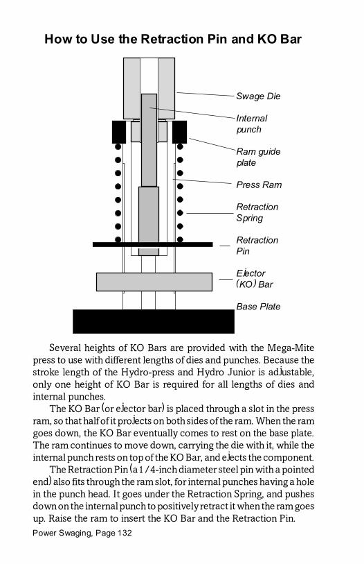
Power Swaging, Page 132
How to Use the Retraction Pin and KO Bar
Several heights of KO Bars are provided with the Mega-Mitepress to use with different lengths of dies and punches. Because thestroke length of the Hydro-press and Hydro Junior is adjustable,only one height of KO Bar is required for all lengths of dies andinternal punches.
The KO Bar (or ejector bar) is placed through a slot in the pressram, so that half of it projects on both sides of the ram. When the ramgoes down, the KO Bar eventually comes to rest on the base plate.The ram continues to move down, carrying the die with it, while theinternal punch rests on top of the KO Bar, and ejects the component.
The Retraction Pin (a 1/4-inch diameter steel pin with a pointedend) also fits through the ram slot, for internal punches having a holein the punch head. It goes under the Retraction Spring, and pushesdown on the internal punch to positively retract it when the ram goesup. Raise the ram to insert the KO Bar and the Retraction Pin.
Swage Die
Internalpunch
Ram guideplate
Press Ram
RetractionSpring
RetractionPin
Ejector(KO) Bar
Base Plate

Page 133
To determine the correct height of K.O. Bar in the Mega-Mitehand press, start with the shortest bar and see if the internal punchcomes to the top or mouth of the die when the ram is lowered all theway. If the internal punch is not pushed to the end of the die,components will not be fully ejected. Change the K.O. Bar until thepunch reaches the top of the die when the ram is all the way down.
If the bar is too tall for the length of punch and die, you won�t beable to lower the ram completely, because the K.O. Bar and punchcombined length will stop the ram movement prematurely. Insertthe height of K.O. Bar which allows the ram to go completely to thebottom of the stroke.
Not every internal punch has a hole for the retraction pin. Thosepunches which require positive retraction have a hole and use thepin, and those which will be pushed down naturally by the fulldiameter component do not use the pin. To insert the retraction pin,put the internal punch into the die and screw the die into the ram.Then raise the ram so that there is room to put the pin under thespring.
Do not insert the pin between coils, because this can damage thespring and may fail to properly position the punch. The pin alwaysgoes beneath the spring. If the hole in the punch not positioned sothat you can put the pin through it, you can unscrew the die slightlyto turn the punch, and use the pointed end of the pin to gently pry thepunch down below the bottom coil of the spring (by inserting the tipof the pin temporarily into the hole, between coils, and working thepunch down).

Power Swaging, Page 134
Maximum Safe Die Pressures
CHP-1 Hydro-presstm (3.25" cylinder)
Caliber Gauge Die Wall Ram Force Internal(inches) Pressure Thickness (Pounds) Pressure
.172 520.7 .364 4,319.6 185,905
.224 839.2 .338 6,962.1 176,667
.243 996.2 .329 8,014.9 172,821
.257 1,062.0 .322 8,810.5 169,842
.264 1,111.0 .318 9,213.1 168,309
.277 1,201.0 .312 9,966.7 165,388
.284 1,251.0 .308 10,375.0 163,777
.308 1,420.0 .296 11,777.0 158,065
.312 1,448.0 .294 12,101.0 157,086
.338 1,628.0 .281 13,509.0 150,557
.358 1,764.0 .271 14,631.0 145,355 .375 1,875.0 .263 15,554.0 140,828.406 2,066.0 .247 17,136.0 132,364.412 2,100.0 .244 17,424.0 130,699.416 2,123.0 .242 17,613.0 129,584.429 2,194.0 .236 18,204.0 125,942.452 2,310.0 .224 19,164.0 119,431.458 2,338.0 .221 19,394.0 117,721.512 2,536.0 .194 21,041.0 102,198
Notes: Maximum gage pressure for the CHP-1 is 2000 psi. Tocalculate the corresponding gage pressure on a CHP-1 equipped with4-inch drive cylinder, take 66% of the gage pressure above (multiply by0.660). When swaging hard materials such as copper, use the startingdiameter of the rod where it contacts the ogive of the point form die,instead of the die caliber, to determine maximum pressure. The pressshould never be set past 2,000 psi on the gage. For core swages, usethe actual diameter instead of caliber. Pressures are for slowly appliedforce: impact or rapid approach of the ram will produce higher initialpressure than the static gauge pressures indicate. Ram travel mayneed to be reduced to less than two seconds per inch with materialshaving a hardness over Bhn 5.

Page 135
Die Pressure per 100 PSI Gage
Caliber Pressure Caliber Pressure
.172 35,703 .355 8,381
.224 21,051 .357 8,288
.243 17,888 .358 8,241
.257 15,992 .366 7,885
.264 15,155 .375 7,511
.277 13,766 .410 6,283
.284 13,096 .412 6,223
.308 11,134 .416 6,104
.312 10,851 .423 5,903
.318 10,445 .429 5,739
.323 10,124 .452 5,170
.333 9,525 .458 5,035
.338 9,246 .475 4,681
.348 8,722 .512 4,029
Note: These figures are accurate for the CHP-1 Hydro-presstm with3.25" drive cylinder.
Formula for gage pressure:
Pg = 1.23PD2
Pg = gage pressure in PSID = caliber (diameter)P = internal die pressure
(This only applies to the CHP-1 Mark IV press with a 3.25" diameterdrive cylinder)

Power Swaging, Page 136
Press Tonnage for Gage Pressure
(CHP-1 Hydro-presstm, 3.25" cylinder)
Gage Pressure Ram Force (lbs) Ram Force (tons)100.0 829.58 .41200.0 1,659.15 .83300.0 2,488.70 1.24400.0 3,318.31 1.66500.0 4,147.88 2.07600.0 4,977.46 2.49700.0 5,807.04 2.90 800.0 6,636.61 3.32900.0 7,466.19 3.73
1,000.0 8,295.77 4.151,100.0 9,125.34 4.561,200.0 9,954.92 4.981,300.0 10,784.50 5.391,400.0 11,614.08 5.811,500.0 12,443.65 6.221,600.0 13,273.23 6.641,700.0 14,932.38 7.471,900.0 15,761.96 7.882,000.0 16,591.54 8.30
Formula for ram tonnage:
T = 0.004148 Pg
Pg = gage pressure (psi)T = tonnage(multiply by 2000 to obtain force in lbs)
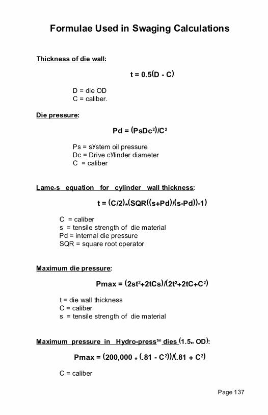
Page 137
Formulae Used in Swaging Calculations
Thickness of die wall:
t = 0.5(D - C)
D = die ODC = caliber.
Die pressure:
Pd = (PsDc2)/C2
Ps = system oil pressureDc = Drive cylinder diameterC = caliber
Lame�s equation for cylinder wall thickness:
t = (C/2)*(SQR((s+Pd)/(s-Pd))-1)
C = calibers = tensile strength of die materialPd = internal die pressureSQR = square root operator
Maximum die pressure:
Pmax = (2st2+2tCs)/(2t2+2tC+C2)
t = die wall thicknessC = calibers = tensile strength of die material
Maximum pressure in Hydro-presstm dies (1.5" OD):
Pmax = (200,000 * (.81 - C2))/(.81 + C2)
C = caliber

Power Swaging, Page 138
Volume in a billet (cylinder):
V = 0.7854 * L * D2
L = length of billetD = diameter of billet
Volume from weight and density:
V = W/d,
W = weightd = density
Weight from volume and density:
W = V * d
V = volumed = density
Length of wire (inches) produced from billet:
L = 1.273 * W/(d * C2)
W = weight of billetd = density of the lead, (.4097 lb./cu-in)C = diameter of lead wire, inches
Weight (lbs) of wire or billet for given length of wire:
W = .7854 * d * C2 * L
d = density of the lead (.4097 lb./cu-in)C = diameter of lead wireL = length of wire
Area of a punch or cylinder:
A = .7854 * C2 or A= Pi * (C/2)2
C = diameterC = w/(id2)

Page 139
Density of material:
d = W/V
W = weightV = volume
Surface area of a cylinder:
A = 3.1416 * C * L + 1.571 * C2
C = diameter or caliberL = length
Weights:
437.5 grains = 1 ounce 16 ounces = 1 pound7000 grains = 1 pound 2000 lbs = 1 ton2204.6 lbs = 1 metric ton 15.43 grains = 1 gram453.6 grams = 1 pound 28.35 grams = 1 ounce
Volume:
16.383 cc = 1 cubic inch1728 cu-in. = 1 cubic foot27 cu-ft. = 1 cubic yard
Water Conversions:
1 gallon = 8.33 lbs= 0.13368 cu-ft.= 231 cu-in.= 3.78 liters= 0.83 Imperial gallon
Power conversions:
1 Horsepower = 746 Watts= 550 foot-lbs/sec.= .707 BTU/sec.

Power Swaging, Page 140
Ballistic Relationships:
E = wv2/2g
S.D. = w/d2
C = S.D./iC = ballistic coefficientw = bullet weight in pounds (lbs.)v = velocity in feet per second (fps)d = diameter of bullet in inches (in.)g = acceleration of gravity (32.16 ft/sec2)i = coefficient of form (Ingall's chart no.)S.D. = Sectional DensityE = kinetic energy in foot-pounds (ft-lb)
Volume of a Half-ball (round nose):
V = Pi d3 / 12
Pi = 3.14159...d = diameter (caliber)
Volume of a Cone:
V = Pi r2 h / 3
r = radius of base (caliber/2)h = height of cone (length from base to tip)
Volume of a Truncated Cone:
V = Pi h (r12 + r
1r
2 + r
22)/ 3
h = height of conical sectionr
1 = radius of base
r2 = radius at tip
Volume of an Elliptical Ogive:
V = Pi a b2 / 3
a = length of ogiveb = caliber

Page 141
12345678901231234567890123123456789012312345678901231234567890123123456789012312345678901231234567890123123456789012312345678901231234567890123123456789012312345678901231234567890123123456789012312345678901231234567890123
r = 1.5 calibers
1 caliber
Ogive begins->Shank ends -->
Bullet's base ->
Bullet tip ->
How to draw a spitzer ogivecurve of a given radius...(1.5-S shown)
Locate pivot ofcompass on per-pendicular fromshank, exactly thenumber of cali-bers of the radiusdesired; scribethe arc connect-ing shank and bul-let centerline.
12345678901234567890123456123456789012345678901234561234567890123456789012345612345678901234567890123456123456789012345678901234561234567890123456789012345612345678901234567890123456123456789012345678901234561234567890123456789012345612345678901234567890123456123456789012345678901234561234567890123456789012345612345678901234567890123456123456789012345678901234561234567890123456789012345612345678901234567890123456123456789012345678901234561234567890123456789012345612345678901234567890123456123456789012345678901234561234567890123456789012345612345678901234567890123456123456789012345678901234561234567890123456789012345612345678901234567890123456123456789012345678901234561234567890123456789012345612345678901234567890123456123456789012345678901234561234567890123456789012345612345678901234567890123456123456789012345678901234561234567890123456789012345612345678901234567890123456123456789012345678901234561234567890123456789012345612345678901234567890123456123456789012345678901234561234567890123456789012345612345678901234567890123456123456789012345678901234561234567890123456789012345612345678901234567890123456123456789012345678901234561234567890123456789012345612345678901234567890123456
123456789012345678901234567890121234567890123456789012345678901234567890121234567890123456789012345678901234567890121234567890123456789012345678901234567890121234567890123456789012345678901234567890121234567890123456789012345678901234567890121234567890123456789012345678901234567890121234567890123456789012345678901234567890121234567890123456789012345678901234567890121234567890123456789012345678901234567890121234567890123456789012345678901234567890121234567890123456789012345678901234567890121234567890123456789012345678901234567890121234567890123456789012345678901234567890121234567890123456789012345678901234567890121234567890123456789012345678901234567890121234567890123456789012345678901234567890121234567890123456789012345678901234567890121234567890123456789012345678901234567890121234567890123456789012345678901234567890121234567890123456789012345678901234567890121234567890123456789012345678901234567890121234567890123456789012345678901234567890121234567890123456789012345678901234567890121234567890123456789012345678901234567890121234567890123456789012345678901234567890121234567890123456789012345678901234567890121234567890123456789012345678901234567890121234567890123456789012345678901234567890121234567890123456789012345678901234567890121234567890123456789012345678901234567890121234567890123456789012345678901234567890121234567890123456789012345678901234567890121234567890123456789012345678901234567890121234567890123456789012345678901234567890121234567890123456789012345678901234567890121234567890123456789012345678901234567890121234567890123456789012345678901234567890121234567890123456789012345678901234567890121234567890123456789012345678901234567890121234567890123456789012345678901234567890121234567890123456789012345678901234567890121234567890
3/4-E
1-E
3/4-E
Common elliptical ogiveshapes (.5-E is the sameas .5-S, a half-ball).Elliptical ogives aremeasured along the bulletcenterline axis from startof ogive to the tip. Theogive is half an ellipse.
Elliptical Ogives
Tangent Ogives

Power Swaging, Page 142
CHP-1 Control Panel
1. Pressure gage (drive pressure)2. Energize button (green, left hand master control switch)3. Position sensors (middle sensor indicated)4. Dwell time control (top of stroke)5. Dwell time control (bottom of stroke)6. Accessory jumper plug/socket (feed-controlled stop)7. 5-Amp control circuit breaker (behind key switch)8. Power key switch (off, manual, auto-stroke) and red Auto light9. Pump motor (20-amp breaker switch)10. Top position sensor reverse on/off switch11. Pressure reversing transducer on/off switch12. Load position stop on/off switch and green load light13. Down button (yellow) and yellow down cycle light14. Up botton (red)15. Drive pressure setting control16. Stroke counter (with reset button)17. Ram speed control (for UP stroke)18. Automatic pressure reverse transducer setting control19. Ram20. Retraction spring (around the ram)
1
2
3
4 5
67
8
9 10 11 12 13 14
15
1617 18
19
20

Page 143
Retraction Pin and Ejector Bar Assembly
Swage Die
Ram GuidePlate
Support Rod
RetractionSpring
Retractionpin
K.O.(ejector) Bar
Base Plate
The Retraction Pin fits through a hole in the internal punch headfor those punches which require it, beneath the last coil of theRetraction Spring. The ram must be raised to insert the pin.
The K.O. (knock-out) or Ejector Bar fits through a slot in the rambelow the Retraction Pin and spring. The head or lower end of theinternal punch rests on the bar when the ram is being lowered. Thebar comes to rest on the base plate. As the ram continues down, thebar and punch are held in position and push the bullet out of the die.
The height of the K.O. Bar and the length of the internal punchare a constant. Short punches use long K.O. Bars and vice versa, inthe hand presses. Power presses have adjustable ejection points anduse just one height of K.O. Bar for all punch lengths.

Power Swaging, Page 144
CHP-1 Hydro-presstm
CHP-1 Hydro-presstm Mark V with dual dwell timers (top andbottom of stroke). First shipped in early 2004. Previous model MarkIV used one dwell timer at top of stroke only.
Shipping weight .................. 350 pounds.Floor space .......................... 22 by 15 inches.Height press head ............... 57 inches.Height to control panel ...... 34 inches.Hydraulic fluid .................... Chevron AW 46, six gallonsMax. ram velocity............... 2 inches/sec.Drive cylinder diameter ..... 3-1/4 inches.Maximum drive pressure .. 2,000 psiDrive pressure range .......... 100 to 2,000 psi (factory max)Dual range pump ................ 500 psi switch point (aprox)Power options ..................... 120v 20a peak, 240v 10a peakIdle current draw ................ 5 amps @ 120v, 2.5 amps @ 240vPosition sensors .................. top, load (middle) bottom setWork lamp ........................... 40w 115v standard base (US)

Page 145
CSP-2H Hydro Juniortm swaging and reloading press.
Shipping weight .................. 300 pounds.Floor space .......................... 22 by 15 inches.Height press head ............... 57 inches.Height to control panel ...... 34 inches.Hydraulic fluid .................... Chevron AW 46, six gallonsMax. ram velocity............... 2 inches/sec.Drive cylinder diameter ..... 3-1/4 inches.Maximum drive pressure .. 2,000 psiDrive pressure range .......... 100 to 2,000 psi (factory max)Dual range pump ................ 500 psi switch point (aprox)Power options ..................... 120v 20a peak, 240v 10a peakIdle current draw ................ 5 amps @ 120v, 2.5 amps @ 240vPosition sensors .................. top and bottom limit switchesWork lamp ........................... 40w 115v standard base (US)
CSP-2H Hydro Juniortm

Power Swaging, Page 146
CHP-1 Mk.V Wiring Diagram

Page 147
Index
A
Air bubble, in pressure gage 74air presses 23air-over-oil system 23Annealing 94area of the punch tip 29AUTO PRESSURE SET knob 72automatic operation 33
B
battery lead 48benchrest grade jackets 90Breakage of dies 31, 86breaking pressure. See Breakage of diesbullet weight 104
C
Casting 11, 44computer program 37, 47Copper tubing 96Corbin Handbook of Bullet Swaging 101�114Cylinder diameter 46
D
Density, lead 46die pressure 31, 34, 38die shoes 18�21Die strength 35die wall thickness 38DOWN button 61Drawn jackets 90
E
Electric power for presses 57ENERGIZE button 61Extruder pressure 46Eyelet presses 18�21

Power Swaging, Page 148
F
Floating punch holder 5�13Fluid, hydraulic. See also Hydraulic fluid
H
hard lead 101�114hollow lead tubing 53hollow tubing 101�102Hydraulic fluid 24, 58hydraulic components 28Hydraulic pressure 24hydraulic system pressure. See also oil pressure
I
impact extrusion 90Inertial presses 17
J
jacket making 90JMK-1-H 91
K
key switch 33knock-out bar 61, 65
L
Lead flow 29Lead Semi-Wadcutter 102Lead wire extrusion 43, 46LED-1 extruder kit 55, 101length of billet Lead extrusion length 46lubrication 47
M
maximum pressure 37
O
OBI presses 17�21oil pressure 30Oil, hydraulic. See Fluid, hydraulic

Page 149
P
Pneumatic Pressure 21position transducer 62pressure reversing 105�114pressure reversing transducer 110PRESSURE SET knob 63, 71, 73Punch 5�13punch press 19, 19�21
R
ram thrust 29, 34. See also ram forceRediscover Swaging 101�114Retracting spring 66Rotational electric power 13
S
safety margin 32shuttle feed 18Soft coiled tubing 94solid rod, swaging 32, 37
T
TimingDwell Timer 6
Tubing jackets 94
U
UP button 61
V
Valve, direction control. See solenoid valve
W
Weight of billet (or spool) 46Weight variation 106wire movement, inches/sec. 51