copyright by sean michael donahue 2016
TRANSCRIPT

Copyright
by
Sean Michael Donahue
2016

The thesis committee for Sean Michael Donahue
certifies that this is the approved version of the following thesis:
Proposed Test Program for Evaluating the Progressive Collapse
Capacity of Steel Framed Composite Buildings
APPROVED BY
SUPERVISIING COMMITTEE:
_________________________________
Michael D. Engelhardt, Supervisor
_________________________________
Howard Liljestrand, Co-Supervisor
_________________________________
Eric Williamson

Proposed Test Program for Evaluating the Progressive Collapse
Capacity of Steel Framed Composite Buildings
by
Sean Michael Donahue, B.S.
Thesis
Presented to the Faculty of the Graduate School
of the University of Texas at Austin
in Partial Fulfillment
of the Requirements
for the Degree of
Master of Science in Engineering
The University of Texas at Austin
August 2016

iv
Proposed Test Program for Evaluating the Progressive Collapse
Capacity of Steel Framed Composite Buildings
by
Sean Michael Donahue, M.S.E.
The University of Texas at Austin, 2016
SUPERVISORS: Michael Engelhardt and Howard Liljestrand
The threat of progressive collapse has been an increased concern for structural
engineers in recent history. Current practice when designing structures to resist
progressive collapse has focused on local strengthening of members and connections, and
the addition of extra structural elements to “tie” the structure together. However, typical
structures have a degree of inherent robustness that is not currently counted on by
designers, which may lessen the need for these additional elements. Many of these
elements that add integrity to the structure have not seen extensive experimental testing,
and their strength and ductility are not fully understood. In an effort to fill this gap, a test
program was designed and implemented to study the response of steel-framed composite
buildings to the loss of a column.
A prototype building was designed by Walter P. Moore to be consistent with current
construction standards and practices. A test building was designed based on this
prototype building, with spans and members scaled down slightly to accommodate the
test frame. Test specimens consisted of a 2-bay by 2-bay section of the test building (in
the case of an interior column loss) or a 2-bay by 1-bay section of the test building (in the
case of a perimeter column loss). The effect of the surrounding building was simulated by
the construction of a heavy restraining beam that circumscribed the test specimen,
providing the restraint that would be present due to neighboring bays. A loading system
and test protocol were designed to allow a uniform floor load to be applied to the test

v
specimen while the column support is removed quasi-statically, with the potential for
further uniform floor load to be added if the specimen survived column loss.

vi
Table of Contents
1 INTRODUCTION 1
1.1 Progressive Collapse .......................................................................................1
1.2 Research Objectives ........................................................................................2
1.3 Scope of Thesis ...............................................................................................3
2 BACKGROUND 5
2.1 Gravity-Framed Steel Buildings .....................................................................5
2.1.1 Components of Gravity Framing ...........................................................5
2.1.2 Design of Gravity Framing ....................................................................9
2.2 Design for Progressive Collapse ...................................................................13
2.2.1 History of Progressive Collapse Design ..............................................13
2.2.2 Current Approaches to Progressive Collapse Design ..........................16
2.2.3 Behavior of Gravity Framing under Column Loss ..............................21
2.3 Previous Research .........................................................................................21
2.3.1 Connection Behavior ...........................................................................22
2.3.2 Floor Systems.......................................................................................34
3 TEST SETUP AND SPECIMEN 46
3.1 Test Concept .................................................................................................46
3.2 Prototype Building ........................................................................................48
3.3 Scaling of Test Specimen..............................................................................50
3.4 Test Specimen Design ...................................................................................51
3.4.1 Primary Structural Members ................................................................51
3.4.2 Connections..........................................................................................53
3.4.3 Floor Slab .............................................................................................54
3.4.4 Additional Specimen Detailing ............................................................57

vii
4 TEST FRAME DESIGN 61
4.1 Foundation Design ........................................................................................61
4.2 Ring Beam Design ........................................................................................62
4.3 Additional Design Considerations ................................................................70
5 TEST PROCEDURE 72
5.1 Actuator Removal .........................................................................................72
5.2 Loading System ............................................................................................73
5.3 Instrumentation .............................................................................................75
5.4 Test Matrix ....................................................................................................78
5.5 Interior Column Loss ....................................................................................79
5.6 Exterior Column Loss ...................................................................................80
6 CONSTRUCTION OF TEST FRAME AND FIRST TEST SPECIMEN 82
6.1 Foundation Pour ............................................................................................82
6.2 Loading System ............................................................................................83
6.3 Test Frame ....................................................................................................85
6.4 Floor System .................................................................................................88
6.5 Concrete Casting ...........................................................................................93
7 SUMMARY AND CONCLUSIONS 95
7.1 Summary of Work .........................................................................................95
7.2 Accuracy of Boundary Conditions................................................................95
7.3 Effect of Scale on Results .............................................................................96
APPENDIX A: TEST SPECIMEN AND FRAME DRAWINGS 98
APPENDIX B: PROTOTYPE BUILDING PLANS 118

viii
WORKS CITED 133

ix
List of Tables
Table 2-1 Moment-Rotation Parameters of Composite Shear Tabs ................................. 28
Table 2-2 Enhancement from Tensile Membrane Action with Orthotropic Reinforcement............................................................................................................................... 39

x
List of Figures
Figure 2-1 Simple Shear Connections (a) shear tab (b) clip angle (c) end-plate (d) tee (e) seated connection (f) stiffened seated connection .................................................. 6
Figure 2-2 Composite Floor Slab Detail ............................................................................. 8
Figure 2-3 Embossments on Composite Decking ............................................................... 9
Figure 2-4 Rotational Ductility of Clip Angle Connection .............................................. 11
Figure 2-5 Tensile Catenary Action .................................................................................. 18
Figure 2-6 Catenary Action of Edge Panel Enhanced by Peripheral Tie ......................... 20
Figure 2-7 Shear Tab Column Loss Test Setup ................................................................ 23
Figure 2-8 Reduced Rotation Demand on Shear Tabs ...................................................... 25
Figure 2-9 Composite Shear Tabs under Hogging Moment ............................................. 26
Figure 2-10 Composite Shear Tabs under Cyclic Load Test Setup .................................. 27
Figure 2-11 Clip Angles under Cyclic Load Test Setu ..................................................... 30
Figure 2-12 Moment Rotation Hysteresis of Clip Angle .................................................. 31
Figure 2-13 Compressive Membrane Action in Concrete Slabs ...................................... 35
Figure 2-14 Tensile Membrane Action in Highly Deflected Slabs .................................. 35
Figure 2-15 Compression Rin ........................................................................................... 36
Figure 2-16 Load Deflection Relationship for Restrained and Unrestrained Slabs with Span to Depth Ratio of 20 ..................................................................................... 37
Figure 2-17 Parametric Study of Deck Thickness Effect on Composite Floor Robustness............................................................................................................................... 41
Figure 2-18 Parametric Study of Connection Strength on Composite Floor Robustness. 42
Figure 2-19 Deck Fasteners under Cyclic Load Test Setup ............................................. 43

xi
Figure 2-20 Floor Plan of Composite Floor Column Loss Test Setup ............................. 45
Figure 3-1 Test Setup Floor Plan ...................................................................................... 47
Figure 3-2 Actuator in Test Setup ..................................................................................... 48
Figure 3-3 Floor Plans for WPM Prototype Building ....................................................... 49
Figure 3-4 Clip Angle Detail and Constructed ................................................................. 54
Figure 3-5 Shear Tab Detail and Constructed ................................................................... 54
Figure 3-6 Deck with Wire Reinforcement Detail and Constructed ................................. 55
Figure 3-7 Reinforcement over Girder Detail and Constructed ........................................ 56
Figure 3-8 Shear Stud Detail over (a) Secondary Beams and (b) Girders ........................ 57
Figure 3-9 Connection from Deck to Beam using Puddle Welds and Tek Screws .......... 58
Figure 3-10 Tek Screw Layout for (a) Floor Beams and Sidelaps and (b) Girders .......... 59
Figure 3-11 Constructed Detail of (a) Girder and Sidelap Tek Screws and (b) Floor Beam............................................................................................................................... 59
Figure 3-12 Longitudinal Seam Detail and Constructed .................................................. 60
Figure 4-1 Foundation....................................................................................................... 62
Figure 4-2 Load-Slip Relationship of Steel Deck-Concrete Composite Bond ................. 64
Figure 4-3 Restraining Beam Detail and Constructed ...................................................... 65
Figure 4-4 Load-Deflection Response of Floor Slab with Ring Beam and Adjacent Bays............................................................................................................................... 66
Figure 4-5 Restraining Beam Connection Drawing and Constructed .............................. 67
Figure 4-6 Restraining Beam Boundary Parallel to Deck Ribs Detail and Constructed .. 68
Figure 4-7 Restraining Beam Boundary Perpendicular to Deck Ribs Detail and Constructed ........................................................................................................... 69

xii
Figure 5-1 Irrigation System ............................................................................................. 75
Figure 5-2 Instrumentation Plan ....................................................................................... 76
Figure 5-3 Floor System Displacing as (a) Rigid Plates and (b) Flexural Shapes ............ 77
Figure 5-4 String Pot Layout at Center Column ............................................................... 78
Figure 5-5 Interior and Exterior Column Test Setup ........................................................ 79
Figure 6-1 Coupler Attachment to Accommodate Short Anchor Rods ............................ 83
Figure 6-2 Constructed Loading Boxes ............................................................................ 85
Figure 6-3 Erection of Restraining Beams ........................................................................ 86
Figure 6-4 Temporary Frame Supporting Central Column .............................................. 87
Figure 6-5 Screw Jacks Supporting Floor System ............................................................ 88
Figure 6-6 Slab Closures (a) Parallel to Deck Ribs and (b) Perpendicular to Deck Ribs . 89
Figure 6-7 Pour Stop Closures and Insulation Sealing ..................................................... 90
Figure 6-8 Reinforcement Layout along Restraining Beam Parallel to Deck Ribs .......... 91
Figure 6-9 Reinforcement Layout along Restraining Beam Perpendicular to Deck Ribs 92
Figure 6-10 Stiffeners Added to (a) Restraining Beam Supports and (b) Middle Column............................................................................................................................... 94
Figure A-1 Test Frame Plans-Specimen Level ................................................................. 99
Figure A-2 Test Frame Plans-Top Level ........................................................................ 100
Figure A-3 Test Frame Elevation ................................................................................... 101
Figure A-4 Test Frame Elevation-Section View ............................................................ 102
Figure A-5 Test Specimen Detail-Column Connection .................................................. 103
Figure A-6 Test Specimen Details-Column Connection-Section View ......................... 104

xiii
Figure A-7 Test Specimen Details-Clip Angle to Ring Beam Connection .................... 105
Figure A-8 Test Specimen Details-Shear Tab to Ring Beam Connection ...................... 106
Figure A-9 Test Specimen Details-Deck Connection ..................................................... 107
Figure A-10 Test Specimen Details-Deck Details .......................................................... 108
Figure A-11 Test Frame Details-Restraining Beam to Corner Column Connection ...... 109
Figure A-12 Test Frame Details-Midspan Column-Ring Beam Connection, Lateral Brace Center Connection .............................................................................................. 110
Figure A-13 Test Frame Details-Column Top Level Connections ................................. 111
Figure A-14 Test Frame Details-Central Actuator Support, Lateral Brace to Ring Beam Connection .......................................................................................................... 112
Figure A-15 Test Frame Details-Corner Column Base Plate ......................................... 113
Figure A-16 Test Frame Details-Corner Footing Foundation Design ............................ 114
Figure A-17 Test Frame Details-Midspan Column Base Plate and Footing Detail ....... 115
Figure A-18 Test Frame Details-Central Actuator Base Plate and Footing ................... 116
Figure A-19 Test Frame Details-Top Level Brace Connections .................................... 117
Figure B-1 Prototype Building-Floor Plan ..................................................................... 119
Figure B-2 Prototype Building-Column and Brace Schedule ......................................... 120
Figure B-3 Prototype Building-Column Splice and Beam to Girder Connection .......... 121
Figure B-4 Prototype Building-Beam to Column Flange Connection............................ 122
Figure B-5 Prototype Building-Spandrel to Column Flange Connection ....................... 123
Figure B-6 Prototype Building-Girder to Column Flange Connection .......................... 124
Figure B-7 Prototype Building-Beam to Column Web Connection ............................... 125

xiv
Figure B-8 Prototype Building-Spandrel to Column Web Connection .......................... 126
Figure B-9 Prototype Building-Girder to Column Web Connection .............................. 127
Figure B-10 Prototype Building-Reinforcement Details ................................................ 128
Figure B-11 Prototype Building-Shear Stud Details ...................................................... 129
Figure B-12 Prototype Building-Decking Perimeter Details .......................................... 130
Figure B-13 Prototype Building-Deck Closure and Sidelap Details .............................. 131
Figure B-14 Prototype Building-Brace Connection Detail ............................................. 132

1
1 INTRODUCTION
This thesis discusses a proposed test procedure for evaluating the resistance of
steel framed composite buildings to progressive collapse. This research was undertaken
as part of a larger project to test the resistance of such buildings to multiple collapse
scenarios with the intent of developing computational models to predict their behavior.
This chapter briefly describes progressive collapse, the response of steel framed
composite buildings to progressive collapse, and outlines the scope of this thesis.
1.1 Progressive Collapse
Progressive collapse occurs when an initiating event causes a collapse that is
disproportionate to the magnitude of the initial event (Starossek 2007). For this reason, it
is also often referred to as disproportionate collapse. Historically, the threat of
progressive collapse was not heavily considered by designers, but events such as the
collapse of Ronan Point Towers in 1968 in London, and more recently the attacks of
September 11 in New York City have spurred engineers to create integrity provisions to
prevent against such failures (Foley 2007). These provisions are often based on tying the
structural elements of a building together, to better enable redistribution of a building’s
loads around the damaged area. The use of these tie forces in resisting progressive
collapse was originally based on research done on reinforced concrete buildings, and
there are still many unanswered questions about how other structures respond to collapse
scenarios, in particular, steel framed composite buildings.
Most elements in a steel framed building are constructed with “gravity framing”,
so called because it is designed only to resist vertical gravity loads. Thus it is not

2
explicitly designed for the high rotations, moments, and lateral forces common in
progressive collapse scenarios. Thus, the current philosophy used when designing such
buildings to resist progressive collapse requires the strengthening of members and
connections, or the placement of additional structural components (typically additional
reinforcing steel in the floor slab). It is recognized that steel gravity framing does have
some inherent resistance to collapse that may lessen or remove the need for this
strengthening, but currently there is insufficient experimental data for engineers to rely
on this inherent robustness (Stevens 2008)
1.2 Research Objectives
The goal of this research is to increase the available experimental data on the
performance of gravity framed steel buildings under collapse scenarios. There are many
components present in these buildings with the potential to contribute significant
robustness to the structure, but their behavior is not sufficiently well understood to be
incorporated into current codes. In particular, the ductility of composite floor slabs is not
fully understood. The strength of the steel decking used in those slabs is also poorly
understood, particularly because of the very limited testing done on the strength and
ductility of the connections used on that decking. The performance of common flexural
connections, particularly when working compositely with a concrete slab, has also
undergone very limited testing.
This project hopes to answer many of those questions by simulating the response
of a typical gravity framed steel building that has not been designed to resist collapse
under a variety of column loss scenarios. The results of these tests will enable us to
evaluate the inherent robustness of this type of construction. By documenting the
response of the structure and the points of failure of each component (if any), the project

3
also hopes to increase our understanding of the behavior of many of the components
counted on to provide robustness. By identifying the most critical points of failure in
typical construction, the project also aims to design and test alternative construction
details that could be used in future structures to improve the robustness of such buildings.
A full understanding of the behavior of all of these components is beyond the
scope of this paper, and beyond this project. Many more tests will be needed before the
response of floor systems under column loss scenarios can be predicted with confidence.
To that end, this thesis details the design and construction of a test frame and procedure
that can be used to test the behavior of gravity framed composite-steel floor systems
subjected to column loss.
1.3 Scope of Thesis
The experimental portion of this research project consists of multiple large scale
tests conducted on the response of a section of a steel framed composite building under
an interior and exterior column loss scenario. The results of these tests, as well as the
computational models developed based on the results, will be discussed in future papers.
This thesis covers the design and construction of the test setup used to simulate the
boundary conditions and loading present in a full structure subjected to a collapse
scenario.
Chapter 2 provides background information on gravity framing and previous
research into its response to column loss scenarios, and background on the history of
progressive collapse design as well as current philosophy. Chapter 3 discusses the design
of the prototype building used for testing, and the test specimens based upon it. Chapter 4
discusses the design of the testing frame. Chapter 5 discusses the test procedure for

4
simulating column loss and the proposed test matrix. Chapter 6 discusses the construction
of the test setup and first test specimen. Conclusions are presented in chapter 7.

5
2 BACKGROUND
This chapter gives an introduction into the typical design and construction of
gravity framed steel buildings with composite floors and discusses the primary
components that affect their behavior. This chapter also summarizes some of the past
research into the behavior of these individual components under collapse conditions.
Finally, the chapter examines the existing empirical and analytical research on full floor
systems.
2.1 Gravity-Framed Steel Buildings
2.1.1 COMPONENTS OF GRAVITY FRAMING
In typical U.S. design practice for steel buildings, lateral loads (wind, seismic,
frame stability) are resisted by a small number of lateral force resisting frames, normally
moment frames, braced frames, shear walls, or some combination of these. The
remainder of the structural system is designed to resist gravity loads (dead, live, snow,
etc.) and normally consists of columns, beams and girders with a composite floor system,
wherein beams are connected to girders, and girders and beams are connected to columns
using “simple shear” connections. There are many connections commonly used in steel
design that are considered simple shear connections including shear tabs, clip angles,
endplates, tees, and seated connections (See Figure 2-1). While there are many different
types of simple shear connections, in conventional design they are all modeled as “perfect
pin” connections, possessing no rotational strength of stiffness. Thus they cannot
contribute to the lateral strength of the structure, which must be provided by moment
frames, braced frames or shear walls placed throughout the structure.

regar
dema
types
on th
single
(typic
called
Fig
Although
rdless of the
and scenario
s of shear co
he performan
e plate con
cally a girde
d web cleat
gure 2-1 Sim
simple she
type used, t
o, such as th
onnections is
nce of shear
nnection) is
er or column
ts) are a sin
mple Shear C(e) seated
ear connectio
the true beh
he loss of a
s beyond the
tabs and cli
a thin plat
n) and then
ngle angle o
Connections connection
6
ons are typi
avior of suc
column) can
e scope of th
ip angles. A
te of steel
bolted to th
or pair of s
(a) shear tab(f) stiffened
ically mode
ch connectio
n vary. Stud
his research
shear tab (a
welded to
he supported
steel angles
b (b) clip angseated conn
eled in the s
ons (particula
dying the re
, so this rese
also called a
the suppor
d beam. Clip
attached to
gle (c) end-pnection
same manne
arly in a hig
esponse of a
earch focuse
a side plate o
rting membe
p angles (als
o the flexura
plate (d) tee
er
gh
all
es
or
er
so
al

7
member and the supporting member. The connections to the flexural member and
supporting member can both be done with bolts or welds. While clip angles are typically
more expensive to construct than shear tabs, they are often used in beam to column
connections, as they can exhibit greater strength and ductility than shear tabs, and their
geometry allows easier attachment to a column web.
These simple shear connections make up the majority of a structure’s framing,
while the structure’s lateral force resisting systems are placed at only a few locations, as
they are significantly more expensive to construct and erect. Their lateral strength must
then be transferred to the rest of the building by use of the floor diaphragm, often
provided by a concrete slab. This slab is typically constructed by placing corrugated
metal decking down over the beams, to which it is usually attached through either puddle
welds or self-drilling tek screws. A concrete slab is then poured on top of it. Through the
use of shear studs welded to the floor beams and extending into the concrete slab, the
concrete also acts compositely with the frame of the structure, enabling it to distribute the
strength of the building’s lateral frames, and enhancing the flexural capacity of the
beams. Figure 2-2 shows a schematic view of a composite floor system.

slab m
is typ
formw
with
slab c
length
flexu
2-3).
inclu
this r
In additio
must also be
pically done
work is non
reinforcing b
can be built
h to prevent
ural reinforce
To control
ded (approx
reinforcemen
on to provid
e designed to
in one of tw
-composite,
bars placed
with compo
t slip betwe
ement for th
shrinkage a
ximately 1%
nt is not cou
Figu
ding compos
o carry the f
wo ways. If
the concrete
in the slab t
osite metal d
en the deck
he slab, rem
and limit cra
by area), us
unted on in
re 2-2 Comp
8
site strength
floor loads to
the corrugat
e slab is des
to provide its
decking. Thi
king and con
moving the n
acking, a sm
sually in the
the analysis
posite Floor
h to the buil
o the beams
ted metal de
signed as a t
s flexural ca
s decking ha
ncrete, which
need for rein
mall amount
e form of a r
s of the struc
Slab Detail
ding frame,
s and girders
ecking used
typical cast
apacity. Alte
as embossm
h enables it
nforcing bars
t of reinforc
reinforced w
cture. The c
the concret
s. This desig
for the slab
in place slab
ernatively, th
ments along it
to act as th
s (See Figur
cement is sti
wire mesh, bu
concrete itse
te
gn
’s
b,
he
ts
he
re
ill
ut
elf

can b
has h
codes
struct
still f
2.1.2
frami
simpl
stiffn
they
the s
be made of
higher therm
s. The thinn
ture, but the
frequently us
DESIGN O
There are
ing, one of
le shear con
ness, and thu
support. Inst
supported m
normal weig
mal resistanc
ner slabs, and
e low cost a
sed (SDI 201
OF GRAVITY
e several as
which is th
nnections of
us do not ex
tead, they ar
members. Sim
Figure 2-
ght concrete
e, allowing
d lower den
and higher av
12).
FRAMING
ssumptions
he “perfect p
a gravity fra
xperience an
re designed o
mple shear
-3 Embossm
9
e, or lightwe
the use of t
nsity of the c
vailability o
that go int
pin” assump
amed buildin
ny flexural d
only to carry
connections
ments on Com
eight concre
thinner slab
concrete, res
of normal we
to the desig
ption of the
ng are assum
demand from
y the shear f
s can also b
mposite Deck
ete. Lightwe
s while still
sult in lowe
eight concre
gn of comp
e shear conn
med to have
m the beam
force impose
be designed
king
eight concret
l meeting fir
er load on th
ete mean it
posite gravit
nections. Th
no rotationa
ms and girder
ed on them b
d to handle
te
re
he
is
ty
he
al
rs
by
a

10
beam’s axial force if used in a braced frame, but that scenario is not within the scope of
this research. Although the connections are typically modeled as perfect pins, all simple
shear connections have some rotational stiffness (particularly after the concrete slab has
been poured), and will experience some flexural demand during the life of the structure.
Thus, shear connections are designed with a minimum rotational ductility, so that the
rotation of the beam does not lead to rupture of the connection. This ductility is typically
provided by prescriptive guidelines on the connection geometry. In the case of
conventional (i.e. not extended) shear tabs, this ductility is assumed to be inherently
present in the bolted connection to the supported member. In the case of clip angles (and
similar connections such as endplates, or tee connections), this ductility can be provided
by bolting the angles to the supporting member. If the connection is welded to the
supporting member, short weld returns are used at the top of the connection, instead of
placing a continuous weld (AISC 2005). Either of these procedures allows the angle to
deform under negative moment, preventing rupture. Note that welding the angle in this
manner allows ductility for negative moment rotation, but does not necessarily provide
ductility for positive moment rotation (which can occur in a column loss scenario) (See
Figure 2-4).

using
suppo
contin
can b
memb
thoug
not c
gravi
over
const
resist
and t
The flexu
g the perfect
orted memb
nuously ove
be counted o
bers are som
gh most com
counted on in
ity framing i
a lost suppo
The desig
truction, wh
t all loads, a
the building
F
ural member
pin assump
bers, with
er multiple b
on to span g
metimes des
mmonly this
n the memb
is designed
rt, either thr
gn of a comp
en the concr
and during th
frame can r
igure 2-4 Ro
rs of a grav
tion, with th
a few exce
beams, will t
greater distan
signed with
is done for
ber’s load ca
as a statical
ough flexura
posite floor s
rete floor sl
he service li
rely on its c
otational Du
11
vity framed
he beams, gi
eptions. Th
take into acc
nces (Canam
negative mo
r serviceabili
arrying capa
lly determina
al or catenar
system can b
ab has not b
ife of the st
composite st
ctility of Cli
building are
irders and sla
he corrugate
count negati
m 2010). Ad
oment reinfo
ity concerns
acity (Ashcra
ate system,
ry action.
be split into
been added
tructure, onc
trength. Wh
ip Angle Con
e also typica
ab all design
ed decking,
ive moment
dditionally, t
forcement at
s to reduce c
aft 2006). O
with no abi
two main p
and the stee
ce the concr
hile the assum
nnection
ally designe
ned as simpl
if it span
capacity an
the composit
t connection
cracking, an
Otherwise, th
ility to bridg
phases: durin
el frame mu
rete has cure
med buildin
ed
ly
ns
nd
te
ns,
nd
he
ge
ng
st
ed
ng

12
loads are typically greatest during the service life of the building, the design of the
flexural members is often controlled by the construction phase of the building, when they
must support the weight of the floor system without relying on composite action. This
weight comes primarily from the concrete while it is being poured, before it has cured.
The Steel Deck Institute recommends a load of 1.6 times the weight of the concrete plus
1.4 times the construction live load (usually assumed to be 20 psf) plus 1.2 times the
weight of the steel decking (SDI 2012). In addition to strength requirements, the beams
must be stiff enough to prevent excessive deflection during pouring of the concrete, as
large beam deflections could lead to an increased weight of concrete being poured to
reach the designed deck thickness. Though there are no explicit specifications limiting
the deflection during concrete pouring, AISC Design Guide 3 recommends limiting dead
load deflections (which includes deflection during concrete pouring) to span length/360.
Modern structures are often built with beams pre-cambered upwards (or, more rarely,
shored at mid-span) to control this deflection while using lighter members (AISC 2003).
The design of the steel decking is similarly controlled by the demands during placement
of the concrete. As with the beams, this design is sometimes controlled by stiffness rather
than strength, with deflections during concrete pouring limited to span length/180 (SDI
2012).
After pouring of the concrete, the composite members must then have the
capacity to carry the building’s service loads. Though there are a variety of load cases,
the controlling case is usually 1.2 times the dead load plus 1.6 times the live load (ASCE
2010). Through the use of shear studs, the steel beams and girders act compositely with
the concrete slab, increasing their strength and stiffness. Due to this large increase, it is
common for a fully composite beam to significantly exceed the capacity demanded by the
design loads (AISC 2003). Thus, the beams and girders are often designed to be partially
13
composite, with the erectors only installing enough shear studs to mobilize a portion of
the concrete deck, usually the minimum portion needed to provide the required flexural
capacity. In some buildings, the percentage of the slab needed to achieve the required
flexural capacity is very small, and in those cases a minimum percentage of composite
action is imposed to prevent excessive slip between the concrete and steel beams. This
percentage varies between engineers, but the engineers consulted on this research
suggested a lower limit of 25%.
The concrete slab must also be designed with sufficient strength and stiffness to
distribute the floor loads to the floor beams. However, the design of the concrete slab is
typically controlled by fire codes (Ashcraft 2006). For floor systems to achieve sufficient
fire resistance (without requiring the addition of supplemental fire proofing to the deck)
a minimum thickness of concrete is needed (typically 3-1/2” above the deck flutes for
lightweight concrete and 4-1/2” above the deck flutes for normal weight concrete) (UL
2015). In most cases, this minimum thickness of concrete provides sufficient stiffness to
span typical distances allowed by the corrugated metal decking. In the case of composite
metal decking, the flexural reinforcement provided by the decking is also usually
sufficient to enable the concrete slab to carry the expected service loads on the floor
without any additional reinforcement (Canam 2010). In non-composite decking, where
the decking cannot provide reinforcement to the slab, reinforcing bars must be added to
the slab to give it the needed strength to carry the building’s service loads.
2.2 Design for Progressive Collapse
2.2.1 HISTORY OF PROGRESSIVE COLLAPSE DESIGN
An early incident that motivated the study of progressive collapse was the
collapse at Ronan Point (A tower block in England) in May 1968. An explosion in the

14
building’s gas line knocked out one of the concrete load bearing walls, leading to the
collapse of a corner of the building (Pearson and Delatte 2005). Due to the location of the
incident, much of the immediate response from the structural engineering community
happened in the United Kingdom. A report filed shortly after the collapse (Griffiths et al,
1968) found that the collapse was partially due to poor workmanship in the construction
of the building, with joints that were not properly constructed. However, the overall
design of the building (and many others in full compliance with then-current building
standards) was deemed incapable of withstanding local damage without the risk of
disproportionate collapse. In response to this report, provisions were added to the U.K.
Building Regulations that required structural members to be able to withstand a pressure
of 34 kN/m2 (4.9 psi) acting on the member (and any cladding attached to it). If the
member cannot withstand this pressure, the provisions required the structure be designed
to remain stable if that member is removed. However, the provisions give relatively little
guidance on how this design is to be carried out (Hendry 1979). The use of member
removal as a method for progressive collapse design will be explained further in section
2.2.2. Later Building Regulations also allowed for the use of horizontal and vertical ties
placed throughout the building in place of the need to design for removal of structural
members, enabling the building to resist collapse through catenary action (Khabbazan
2005). The use of tie forces and catenary action to resist collapse will be explained in
greater detail in section 2.2.2.
The development of progressive collapse provisions in the United States was
less immediate, and focused more on the performance of precast concrete structures (the
style of construction used in Ronan Point), instead of general structural performance
(Foley 2007). The U.S. approach also focused more on utilizing the robustness already
present in existing design. Initial ACI integrity provisions required continuity of column

15
reinforcement and temperature and shrinkage reinforcement in the slab to tie the structure
together, and provide a minimum level of catenary action (Popoff 1975). Later work by
Hawkins and Mitchell (1979) and Mitchell and Cook (1984) looked more closely at the
formation of catenary action in concrete slabs, and came up with continuity provisions
that form the basis of the current ACI integrity provisions. These require a minimum
portion of reinforcement in beams and slabs be continuous (or spliced to develop their
full tensile capacity) throughout the floor system, and this reinforcement must be
anchored to supports at the perimeter of the structure (ACI 2008).
Comparatively little research has been done in the U.S. on the resistance of steel
buildings to progressive collapse. It was primarily in response to the collapse of the
World Trade Center in 2001 (as well as attacks on U.S. owned buildings outside the
country in previous years) that significant provisions were created to provide integrity
requirements in steel structures, but these provisions are still limited (Geschwindner
2010). The American Society of Civil Engineers (ASCE) Standard 7-10: Minimum
Design Loads for Buildings and Other Structures includes general integrity provisions.
These provisions are primarily designed to provide a continuous load path in the
structure, requiring (among other things) all members to be connected to the rest of the
structure with connections capable of handling a lateral load equal to 5% of the vertical
load imposed on the connection. The International Building Code (2009) also provides
structural integrity provisions that require beam and girder connections to have a tensile
capacity equal to 2/3 of the connection’s required shear strength. The use of these
provisions will likely provide some robustness to steel structures, but leave out
considerations that could be relevant to the collapse resistance of steel buildings.
While integrity provisions for general steel structures are currently limited, more
developed guidelines are currently in place for many federal buildings constructed in the

16
U.S. or by U.S. interests abroad. In 2003, the General Services Administration (GSA)
published the Progressive Collapse Analysis and Design Guidelines for New Federal
Office Buildings and Major Modernization Projects (GSA 2003). These guidelines
(originally published in 2000 as a guide for designing robustness in concrete structures,
expanded to include steel in this edition) provided two methods for designing structures
to resist progressive collapse. One method was a series of exemptions, where a structure
could be considered not at risk of progressive collapse if it possessed certain structural
characteristics, primarily a high degree of connection ductility and axial strength. If it
was not exempt, the building’s response to multiple column loss scenarios would need to
be analyzed, and the performance of its components compared against failure criteria
established by the Guidelines. In 2005, the Department of Defense published the Unified
Facilities Criteria (UFC) document Design of Buildings to Resist Progressive Collapse
(UFC 2005). This document (later updated in 2009) has many similarities to the GSA
Guidelines, but also outlines other approaches to designing buildings to prevent
progressive collapse, including the use of tie forces seen in the Building Regulation and
ACI provisions. While the UFC guidelines only currently apply to certain federal
buildings, they are (in the author’s opinion) the most comprehensive set of standards in
use in the U.S. today, and they will be used as a basis for discussing current approaches
to progressive collapse design in the next section.
2.2.2 CURRENT APPROACHES TO PROGRESSIVE COLLAPSE DESIGN
In the time period immediately following the Ronan Point collapse, some
guidelines tried to address the risk of progressive collapse by subjecting the building
components to blast loads that were deemed representative of what would be seen in a
collapse scenario (Griffith et al 1968). Such provisions are still in place in the UK

17
Building Regulations. However, many engineers have raised the objection that such loads
are inherently arbitrary, as a determined attacker can almost always attack with a load
slightly more than the design load (Foley 2007). Current approaches to progressive
collapse design more commonly try to achieve general robustness with an event-
independent approach, typically designing the structure to withstand the loss of a single
key structural member (usually a column) without the collapse of a disproportionate
portion of the structure. There are two approaches commonly used to design structures to
resist collapse in the event of member removal: the indirect design approach, which
provides general robustness to the structure through ensuring high degrees of continuity
and ductility in the building components, and the direct design approach, where a full
analysis is carried out on a model of the structure with one column removed, and the
response of the structure is evaluated to determine if a disproportionate percentage of the
structure collapses.
An example of indirect design for progressive collapse is the Tie Force approach
in the UFC Guidelines. Though this section discusses the UFC guidelines, most of the
conclusions are based on Assessment and Proposed Approach for Tie Forces in Framed
and Load-bearing Wall Structures, the 2008 report by David Stevens that formed the
basis for the 2009 UFC Guidelines (Stevens 2008). This approach relies on the formation
of catenary action to allow the building to bridge over a removed column. Catenary
action (also called membrane action in the case of plane elements) is the ability of a
structural element to resist transverse loads using purely axial tension forces by
undergoing large deflections, behaving similar to an cable (see Figure 2-5). Such
displacements are too large to be permissible under service conditions, but in collapse
scenarios, large deflections can be tolerated if the structure remains stable. If large
deflections are allowed, the use of catenary action can be very beneficial, as it allows thin

eleme
larger
floor
preve
axial
system
ducti
rotati
shape
defle
These
these
span.
bays.
to a p
calcu
These
the ti
ents (such a
r than they
slab, if pro
enting collap
capacity un
m must pos
lity at the en
While it
ion capacity,
e and maxim
ction is bas
e tests will b
tests, the au
Note that du
The guideli
parabola). U
ulated for an
e assumption
e forces mus
as the floor s
would typic
operly reinf
pse of the st
nder very la
sess a high
nds of the ele
is possible
, tie force pr
mum deflec
ed on a ser
be discussed
uthors of the
ue to the rem
ines also ass
Using this ass
ny regularly
ns on displac
st be provide
Fi
slab of a bu
cally be abl
forced with
tructure. Thi
arge displace
degree of bo
ement).
to calculate
rovisions, to
ction. In the
ries of tests
d in greater
e UFC guide
moval of the
sume the for
sumed shape
framed bui
ced shape ar
ed by elemen
gure 2-5 Ten
18
uilding) to ef
le to span u
horizontal
is capacity i
ements, whi
oth strength
the needed
remain simp
e case of t
done on co
detail in sec
elines decide
column, thi
rmation of a
e, the needed
lding, using
re critical to
nts that have
nsile Catena
fficiently sp
under purely
ties, can sp
is dependent
ich means t
h and ductilit
d catenary s
ple, will typ
the UFC gu
oncrete slabs
ction 2.3.2.1
ed on a defle
is span length
a true catenar
d horizontal
g simply its
the calculati
e the ductilit
ary Action
pan large dis
y flexural ac
pan over a
t on the slab
that an effic
ty (particula
strength for
ically assum
uidelines, th
s under high
1. Based on
ection limit o
th consists of
ry shape (ro
tie forces ca
bay size an
ion of tie for
ty to achieve
stances, muc
ction. Thus,
lost column
b retaining it
cient catenar
arly rotationa
any arbitrar
me a displace
his maximum
h deflection
the results o
of 10% of th
f two framin
oughly simila
an be quickl
nd floor load
rces, and thu
e the assume
ch
a
n,
ts
ry
al
ry
ed
m
ns.
of
he
ng
ar
ly
d.
us
ed

19
shape. Concrete slabs (cast in place, composite decks, or topping slabs) that are
traditionally reinforced are assumed to have this minimum ductility. Any other element
that is intended to provide a tie force must be shown capable of carrying the tie force
while undergoing a 0.2 radian rotation.
For catenary action to function effectively, vertical and lateral restraint must be
provided at the perimeter of the affected area. In some instances, this lateral restraint can
be provided by the slab itself, through a “compression ring” mechanism, discussed
further in section 4.2. However, for certain locations of column removal, sufficient
restraint cannot be provided by the undamaged portion of the structure. If an edge column
is lost, restraint can be provided in the direction parallel to the edge by the surrounding
beams, but the tensile membrane cannot form in the direction perpendicular to the edge.
To improve the catenary capacity of the structure, a peripheral tie is also placed around
the perimeter of the structure. This peripheral tie provides limited restraint to the tensile
membrane perpendicular to the edge of the building, improving the efficiency of the tie
forces. (See Figure 2-6) In the case of column loss at the corner of the structure or
immediately next to the corner (i.e. the penultimate column), it is prohibitively difficult to
provide sufficient restraint to effectively support the catenary action of the slab. Thus,
design for tie forces typically also involves Enhanced Local Resistance, strengthening the
corner and penultimate columns, and designing them for ductile failures.

altern
remo
this a
speci
The
colum
guide
allow
ampl
non-l
of the
force
behav
the st
Fig
The other
nate path app
ved, and red
approach has
ific guideline
UFC guide
mns must be
elines are sim
w for the a
ification fac
linear effects
e structural e
-controlled
viors) specif
tructure can
ure 2-6 Cate
r approach t
proach, anal
designing an
s been ackno
es on how t
elines provid
e removed an
milar to the
analysis of
ctors applied
s, a non-line
elements are
behaviors)
fied by the g
withstand th
enary Action
to progressiv
lyzing the re
ny componen
owledged as
this analysis
de specific
nd the analy
procedure c
the structu
d to forces
ear static mo
e then compa
or rotation
guidelines. A
he loss of the
n of Edge Pa
20
ve collapse
esponse of th
nts that are
s a method o
should be c
procedures
ysis of the st
created in th
ures with a
and displac
odel, or non-
ared to their
limits (in
Any compone
e column wit
anel Enhance
design in th
the structure
overloaded
of creating r
carried out a
and accept
tructure after
he GSA guid
an elastic
ements to a
-linear dynam
load-carryin
the case o
ents that fail
thout ruptur
ed by Periph
he UFC Guid
e if one of th
in that scen
robustness fo
are compara
tance criteri
r member re
delines). The
model, wit
account for
mic model.
ng capacity (
f deformati
l must be red
re of its elem
heral Tie (Ste
delines is th
he columns
nario. Thoug
or some time
atively recen
ia for whic
emoval (thes
ese guideline
th prescribe
dynamic an
The respons
(in the case o
on-controlle
designed unt
ments.
evens 2008)
he
is
gh
e,
nt.
ch
se
es
ed
nd
se
of
ed
til

21
2.2.3 BEHAVIOR OF GRAVITY FRAMING UNDER COLUMN LOSS
The typical design approach to gravity framing results in a building with limited
redundancy against the loss of a support. The connections are assumed to have no
flexural strength, and thus a lost column would result in the formation of a mechanism in
the beam. Although the connections do have some axial capacity, the rotational capacity
of the connections is believed to be relatively limited, and thus not able to deflect enough
to provide meaningful catenary support. The composite decking used to support the
concrete during casting also has significant axial capacity, but the continuity of the
decking (primarily its ability to carry axial load over seams in the deck) and the rotational
capacity of the deck have not been sufficiently investigated to be relied on in design
(Stevens 2008). Despite these limitations, there is some inherent robustness in gravity
framed steel structures. However, the experimental data on this robustness is limited.
Further research is needed to better understand the response of these elements under a
column loss scenario, so the collapse performance of gravity framed steel building can be
better understood.
2.3 Previous Research
Few researchers have looked at the total system response of steel framed
composite buildings under column loss scenarios. However, there has been testing done
on many of the components of such buildings under conditions similar to those in a
building experiencing a column loss. A summary of many of these tests, and how their
findings may impact such a structure’s robustness, is presented below.

22
2.3.1 CONNECTION BEHAVIOR
2.3.1.1 Shear Tabs
There has been limited experimental testing done on the behavior of shear tabs
under progressive collapse scenarios. Shear tabs are usually assumed to be too brittle to
add to a building’s robustness. The UFC guidelines specify a maximum rotation of
approximately 0.05 radians for shear tabs that are expected to contribute to a buildings
collapse resistance, significantly less than the .2 radians assumed for catenary action.
Despite their limited rotation capacity, neglecting their contribution to a building’s
collapse response may be an overly conservative assumption.
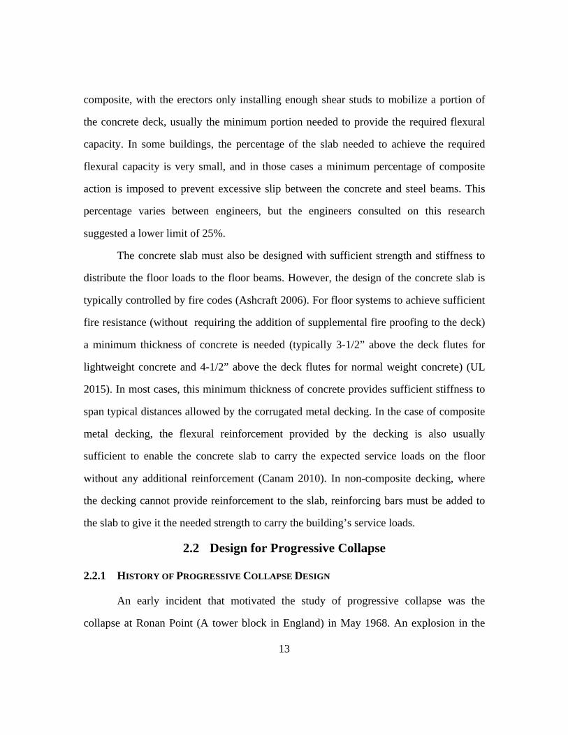
Testing done by Thompson (2009) at the Milwaukee School of Engineering
simulated the response of shear tabs in a column loss scenario. Beams were attached to
opposite sides of a central column by shear tabs of various depths, and pinned at their
opposite end. The column was then pulled down, to induce the displacements present
after column loss, and the load-deflection responses of the connections were recorded
(See Figure 2-7). These tests showed that shear tabs could develop flexural and catenary
capacity in a highly displaced floor system, but that these capacities are limited. Using
this research’s prototype building (discussed in section 3.2) as a typical building, the
expected flexural and axial demands using the UFC alternate path and tie force
provisions, respectively, are greater than any of the observed capacities. Additionally,
the connections exhibited limited flexural ductility, with moment capacities typically
reaching their peak at rotations of approximately .07 radians, and quickly dropping off at
higher rotations. This limited ductility means the flexural capacity likely cannot work in
conjunction with the catenary capacity of the system, as the connections only exhibited
significant axial load after the flexural capacity began to drop off. The shear tabs’ axial
response exhibited higher rotational capacity, supporting large tensile loads until its
failur
withs
ducti
to the
depth
signif
failin
rotati
The d
more
incre
streng
of lar
loss s
re due to bo
stand a colum
le enough to
e building’s
The tests
hs on the c
ficant effect
ng at lower f
ions of 0.13
deeper conne
bolts. The
ased connec
gth or ductil
rger, stronge
scenario.
Figu
olt tear-out i
mn loss scen
o contribute
robustness.
done by Th
onnections’
t on the beh
final rotation
radians, dro
ections also
flexural cap
ction depth,
lity to contri
er shear tabs
re 2-7 Shear
n the shear
nario on its
to the floor
hompson als
behavior. T
havior, with
ns. The shall
opping off to
exhibited lit
pacity of the
but, as state
ibute signific
s may actual
r Tab Colum
23
tab. While
own, the sh
system’s me
so examined
This varying
h deeper con
lowest conne
o 0.9 radians
ttle gain in a
e connection
ed earlier, th
cantly to the
lly lead to a
mn Loss Test
this capacity
hear tab’s ca
embrane act
d the effect
g depth of
nnections th
ection (with
s for the deep
axial capacit
n did show s
his capacity
e building’s
a reduced ab
Setup (Thom
y is likely n
atenary behav
tion, and cou
of different
connections
hat have mo
h three bolt r
per five bolt
ty despite th
significant in
likely does
robustness.
bility to surv
mpson 2009
not enough t
vior could b
uld contribut
t connection
s did have
ore bolt row
rows) reache
t connection
he presence o
ncreases wit
not have th
Thus, the us
vive a colum
9)
to
be
te
ns
a
ws
ed
ns.
of
th
he
se
mn

24
Though the use of deeper shear tabs may not improve a building’s robustness, it
may be possible to increase the collapse performance of shear tabs through other
methods. In particular, the shear tabs tested all failed through tear-out of the shear tab,
where the shear tab did not have enough horizontal edge distance to fully develop the
bolt’s bearing capacity. By slightly extending the shear tab, its ability to support tension
along its axis could be greatly improved, significantly raising its catenary contribution,
with negligible increase in construction cost. This could also change the failure mode
however, causing the connections to fail via bolt fracture, resulting in a more brittle
failure that cannot work compositely with the rest of the system. Shear tab performance
could also be improved through the use of slotted holes, or other methods not yet
considered. While looking at all of these parameters is beyond the scope of the project,
there is potential for the use of different details in future tests.
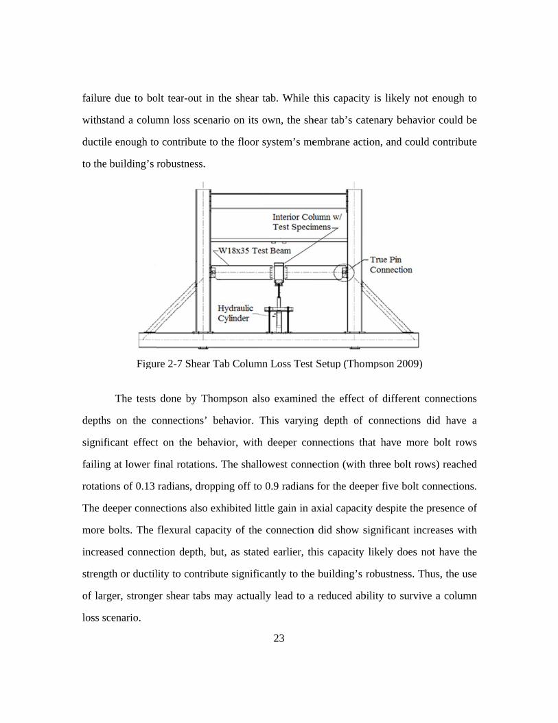
An important facet when considering the contribution of shear tabs to the
behavior of a floor system is their location in typical floor systems. While typical practice
varies from designer to designer, shear tabs are more commonly used in beam-to-girder
connections, and less frequently used to connect flexural members to columns (Waggoner
2012). This means that in a column loss scenario, shear tabs are typically located away
from the point of greatest deflection, and are subsequently called upon to undergo less
rotation than the column connections, which may enable them to continue contributing
capacity through catenary action even if the floor system undergoes a greater total
rotation (See Figure 2-8)
2.3.1
collap
the c
respo
Alter
conne
the fl
comp
Xiao
mom
conne
ends
did n
but s
perfo
.2 Compos
Another v
pse scenario
concrete slab
onse of the
rnatively, by
ection more
loor’s system
To the au
posite shear
et al (199
ments. Two
ections, and
of the beam
not include th
still reveal
ormance.
site Effects
very importa
os is the effe
b above the
e shear tab
y stiffening
brittle, caus
ms strength u
uthor’s know
tab connect
4) studied
cantilever b
d a composit
ms were then
he effect of c
some insig
Figure 2-8
on Shear T
ant compone
ct of compo
e connection
b, by addin
g the conne
sing it to fai
under collaps
wledge, there
tions under
the respons
beams were
te concrete
loaded dow
catenary forc
ghts into th
Reduced Ro
25
abs
ent of the re
osite behavio
n has the po
ng strength
ection, the
l at a lower
se scenarios
e has been l
progressive
se of compo
e framed in
slab was ca
nward until
ces, or exam
he effect o
otation Dem
esponse of s
or on the con
otential to s
and stiffn
composite
rotation, red
.
limited expe
e collapse co
osite shear
nto a centra
ast over the
failure of th
mine the resp
of composite
mand on Shea
shear tabs to
nnection. Th
significantly
ness to the
action coul
ducing its co
erimental tes
onditions. T
connections
al column b
beams. The
he connection
ponse to posi
e action on
ar Tabs
o progressiv
he presence o
improve th
e connection
ld make th
ontribution t
sting done o
Tests done b
s to hoggin
by shear ta
e cantilevere
n. These test
itive momen
n connectio
ve
of
he
n.
he
to
on
by
ng
ab
ed
ts
nt,
on

impro
streng
brittle
Signi
reinfo
rotati
to ac
desig
perfo
to ser
the c
large
Astan
The prese
oved the sti
gth of the c
e behavior,
ificant impr
orcement to
ions several
chieve this i
gners to con
ormance wer
rve as addit
onnections w
st rotation c
neh-Asl (200
Figure 2-9
ence of a ty
ffness of th
connections.
failing at
rovements i
o the concr
times larger
improvemen
ntrol crackin
re achieved b
ional reinfor
was still no
capacity rec
00) on the pe
Composite S
ypical comp
he tested con
Additionall
.026 radian
n connectio
rete slab, w
r than that of
nt is minima
ng (Ashcraf
by orienting
rcement. De
oticeably sho
corded was
erformance o
Shear Tabs u
26
posite slab (
nnections, bu
ly, the conn
ns due to fr
on behavior
with such c
f the unmod
al, and is so
ft 2006). Si
the decking
espite this im
ort of the .2
.08 radians)
of composite
under Hoggi
(with only s
ut did not s
nection with
fracture of t
r were achi
connections
dified slab. T
ometimes in
imilar impr
g ribs paralle
mprovement
2 radians ass
). Tests wer
e shear tabs
ng Moment
shrinkage re
significantly
h a typical s
the reinforc
ieved by ad
reaching m
The reinforce
ncluded in fl
rovements in
el to the beam
t, the rotatio
sumed for ti
re also done
under cyclic
(Xiao et al 1
einforcemen
y improve th
slab exhibite
cement mesh
dding furthe
moments an
ement neede
floor slabs b
n connectio
m, allowing
on capacity o
ie forces (th
e by Liu an
c loads whic
1994)
nt)
he
ed
h.
er
nd
ed
by
on
it
of
he
nd
ch

studie
tests
respo
on a
centr
of th
beam
allow
to th
appli
the ro
and r
tabs e
and c
capac
Fi
ed moment
also did not
onse of conn
series of bea
al column w
e beam. Th
m size, and pr
wed the speci
e column, i
ed cyclically
otation reach
rotation in th
The conn
exceeding .1
crushing of
city decrease
igure 2-10 C
and rotation
include the
ections to bo
am “strips”,
with shear ta
e parameter
resence and
imen to have
inducing rot
y, with gradu
hed .15 radia
he connection
nections exhi
1 radians of r
f the concre
ed as the con
Composite Sh
n capacity o
axial forces
oth positive
consisting o
abs, with an
rs investigate
reinforceme
e a gravity l
tations in th
ually increas
ans (the max
ns was moni
ibited signif
rotational ca
ete around t
nnection dep
hear Tabs un
27
of these conn
s present in a
and negative
of two floor b
8 foot wide
ed by the te
ent of concre
load imposed
he shear tab
sing displace
ximum perm
itored throug
ficant rotatio
apacity befor
the column.
pth increase
nder Cyclic L2000)
nections und
a collapse sc
e moments.
beams attach
e composite
esting includ
ete. The test
d on it while
b connection
ements, unti
mitted by the
ghout testing
on capacity,
re failing via
As in prev
d, but there
Load Test Se
der high rot
cenario, but
The tests we
hed to oppos
concrete sla
ded depth o
t frame (See
e lateral drif
ns. This late
il the connec
e test setup).
g.
with all com
a fracture in
vious tests,
are not eno
etup (Liu an
tations. Thes
did study th
ere conducte
site sides of
ab cast on to
of connection
e Figure 2-10
ft was applie
eral drift wa
ction failed o
The momen
mposite shea
the shear tab
this rotatio
ough points t
nd Astaneh
se
he
ed
f a
op
n,
0)
ed
as
or
nt
ar
b,
on
to

estim
incre
studie
shear
mom
prese
enoug
capac
the a
under
Howe
conne
durin
flexu
the s
reduc
than
mate the prec
ase in rotati
ed exhibited
r tabs studie
ment (see Err
ent in the do
gh to suppo
city of the bu
Whether
available dat
r small rotat
ever, this w
ections only
ng a monoton
ural capacity
ystem (due
cing its ducti
the Thomp
Table
ise nature of
ion capacity
d significant
ed, this capa
ror! Referen
ouble span s
rt the floor
uilding if it c
or not these
ta though. T
tions, with th
weakening ef
y reached h
nic loading s
would unde
to catenary
ility. It is us
pson test (w
e 2-1 Mome
f this relation
over the te
moment cap
acity was be
nce source
cenario crea
loads by its
can act in tan
e mechanism
The connect
he moment
ffect could b
high rotation
scenario (su
ergo less deg
y forces) cou
seful to note
which includ
nt-Rotation
28
nship. It is n
sts done by
pacity under
etween 36 a
not found.)
ated by a los
self, but cou
ndem with th
ms can work
tions exhibit
capacity dro
be due to th
ns after bein
ch as would
gradation. C
uld damage
that these te
ded axial e
Parameters o
not clear at th
Xiao. Addi
the high rot
and 45 perce
. Due to the
st column, t
uld provide a
he building’
k together is
ted much h
opping off a
he cyclic na
ng repeatedl
d be seen in
Conversely, t
e some elem
ests showed
effects), thou
of Composit
his point wh
itionally, the
tations. For t
ent of the b
e very high f
this capacity
a significant
s catenary re
difficult to
higher mome
as the rotatio
ature of the
ly loaded. I
a column lo
the presence
ments in the
d greater flex
ugh the rea
te Shear Tab
hat caused th
e connection
the composit
eam’s plasti
flexural load
y is likely no
t boost to th
esponse.
discern from
ent capacitie
ons increased
e tests, as th
It is possibl
oss event), th
of tension i
connection
xural ductilit
ason for th
bs
is
ns
te
ic
ds
ot
he
m
es
d.
he
le
he
in
ns,
ty
is

29
difference is not clear. Thus, the true ductility of composite shear tabs in column loss
scenarios is difficult to predict at this point.
Also of note, the reduction in moment capacity at high rotations was much higher
in instances where the beam connected to the column’s web, rather than to the column’s
flanges. When connected to the column web, the concrete is forced to primarily react
against only the edge of the column flanges, reducing the available bearing area. This
could cause it to crack earlier, leading to the reduction in moment capacity. Conversely,
when oriented so the concrete could bear against the full column flange, the reduction in
moment capacity was much lower, losing approximately 25% of their max capacity, as
opposed to the 50% reduction seen in the other orientation. If the shear tabs are used to
connect flexural members to girders (as it is in our prototype building) the concrete slab
would be continuous between the connections. This would likely provide sufficient
bearing area to exhibit this favorable behavior. Alternatively, the loss in capacity could
be an artifact of the different maximum rotations. The shear tab connections used in the
column web connections in this test had shorter connection depths than those in the
flange connections, and thus reached a larger rotation before failing. This increased
rotation could account for the higher reduction in moment capacity. Thus, although these
connections have the potential to increase a structure’s robustness, there are still many
questions that need to be answered before their capacity can be counted on by practicing
engineers.
2.3.1.3 Clip Angles
Like shear tabs, clip angles are often assumed to have insufficient strength and
stiffness to contribute more than shear resistance to most steel framed structures. Thus,
their performance under collapse conditions has undergone limited testing. Work done by

Astan
angle
doub
was t
conne
tear o
that f
speci
longe
speci
great
the pl
deter
F
neh et al (19
e connection
le angle con
then rotated
ection or the
The conne
out, or failur
failed via bol
imens that fa
er common i
imens conne
er strength a
lastic mome
ioration in c
Figure 2-11
989) at the U
ns under cycl
nnection wel
d through cy
e test maxim
ections exhib
e of the angl
lt tearing exh
ailed via bolt
n modern co
cted with A3
and ductility
nt of the atta
apacity up to
Clip Angles
University o
lic loading.
lded to the
ycles of unif
mum of .06 ra
bited two m
les by fractu
hibited limit
t tear-out we
onstruction p
325 bolts all
. The conne
ached beam,
o their failur
s under Cycl
30
of Berkeley l
Different be
beam web a
formly incre
adians.
ajor failure m
ure at points
ted ductility,
ere connecte
practice). Th
l failed throu
ections achie
, and maintai
res at rotatio
ic Load Test
looked at th
eams were a
and bolted t
easing rotati
modes: failu
of high yield
, but it is imp
d with ribbe
he specimens
ugh angle fra
eved between
ined that lev
ons of approx
t Setup (Ast
he performan
attached to a
to the colum
ions, up to f
ure of the bol
ding. The co
portant to no
ed bolts (a fa
s with thinne
acture after e
n 10 and 20
vel with min
ximately .05
taneh-Asl et
nce of doubl
a column by
mn. The beam
failure of th
lts via thread
onnections
ote that all
astener no
er angles and
exhibiting
percent of
imal
5 radians
al 1989)
le
a
m
he
d
d

(see)
high
conne
tighte
typic
highe
welde
tests,
eccen
incre
result
angle
that
conne
F
. While this
load, and fat
ections were
ened, which
al gravity fra
er rotation ca
Similar re
ed-bolted do
with a can
ntric actuato
asing displa
ted in a brit
e yielding th
failure of t
ection, impr
Figure 2-12 M
rotation cap
tigue likely c
e all pre-tens
can improve
aming in a m
apacities, an
esults were o
ouble angle c
ntilever beam
r first throug
acement step
ttle connecti
he connectio
the angle c
roving duct
Moment Rot
acity is limit
contributed t
sioned, while
e their rotati
monotonic lo
d contribute
obtained from
connections
m attached t
gh a series o
ps. The tes
ion failure a
on exhibited
could be fo
tility with m
tation Hyster
31
ted, the failu
to their failu
e typical gra
on capacity
oading scena
meaningful
m cyclic test
. A similar t
to a fixed c
of increasing
sts again sh
at low rotati
higher duct
orced by in
minimal de
resis of Clip
ures occurred
ure. Also of n
avity framed
(Fleischman
ario (like col
lly to a build
ts done by A
test setup wa
column and
g load steps,
howed that
ion, but if t
tility. The te
creasing the
ecrease in u
p Angle (Ast
d after sever
note is that t
connections
n et al 1991)
lumn loss), c
ding’s robust
Abolmaali et
as used as in
then loade
, then throug
failure via
the connecti
est program
e column g
ultimate stre
taneh-Asl et
ral cycles of
the tested
s are snug-
). Thus,
could exhibit
tness.
t al (2003) o
n the Astane
d through a
gh a series o
bolt fractur
ion failed vi
also showe
gauge of th
ength of th
al 1989)
t
on
eh
an
of
re
ia
ed
he
he

32
connection. As before, despite the connections exhibiting significant strength and
ductility, these values might not be sufficient to withstand a column loss scenario. The
ultimate moment capacity of the connections was approximately 10 to 15 percent of the
demand that would be seen on such a connection in a column loss event (based on the
floor loads and spans in our prototype building). The connections also failed at rotations
less than .04 radians, although it should be noted that failure was defined as the point
when further cycles did not result in an increase in connection moment, not a complete
loss in connection capacity. This rotation at maximum moment is consistent with the
rotation at maximum moment seen in the shear tab tests mentioned previously, which
exhibited significantly more rotational capacity before failure. It is possible that the clip
angles could continue to carry load under much higher rotations and exhibit more
ductility in a true collapse scenario.
While these results tell us a great deal, it is difficult to compare these findings
directly to those present in a progressive collapse scenario. First, the tests were done on
the cyclic response of the connections. Since the angles yielded several times before
fracture occurred, it is likely fatigue played a significant role in the final failure point of
the connections, and an angle subjected to the monotonic load present in column loss
scenarios could exhibit significantly more rotation capacity. Conversely, the testing done
does not include the tensile forces that would be imposed on the connection by the
membrane action of the deflected system. The addition of that tensile force could place
more stress on the connection leading to it fracturing at an earlier point.
Unfortunately, this is only one of the many unknowns encountered when studying
the response of double angles under collapse conditions. In particular, the presence of a
concrete slab above the clip angle connection will likely provide a significant increase in
moment capacity. Whether this moment capacity is retained at high enough rotations to

33
contribute significantly to the building’s collapse response, and whether the slab has a
significant effect on the ductility of the connections response are both unknown, as they
have never been empirically tested to the author’s knowledge. Likewise, the effect of
catenary forces on the connection could also play a large role in the connection’s
behavior, but has not been experimentally investigated.
2.3.1.4 Composite Effects on Clip Angles
Leon (1990) examined the rotational strength and stiffness of various composite
shear connections under cyclic loads. While most of these tests focused on different types
of seat angle configurations, one test on clip angle behavior was conducted. Due to the
limited size of the test matrix, it is difficult to draw many conclusions from this series of
tests, but the results can be compared with non-composite clip angles tested by Astaneh-
Asl and Abolmaali. The presence of a composite slab seems to significantly increase the
moment capacity of the connection, achieving up to twice the moment capacity of
similarly sized bare steel connections, with similar increases in stiffness. While this
increased capacity is likely not enough to support the significant increase in flexural
demand in a typical column loss scenario, it does possess the potential to contribute
significantly to the building’s robustness if it can act in concert with the rest of the floor
system. Unfortunately, the rotational ductility of composite clip angles is still unknown,
as the tests done by Leon were stopped at 0.3 radians, while the connections appeared to
have some residual capacity. It is also important to note the connections tested by Leon
were very heavy clip angles, with a heavily reinforced slab. Whether their high moment
capacity is present in lighter connections, with less reinforced slabs is still unanswered.

34
2.3.2 FLOOR SYSTEMS
2.3.2.1 Membrane Theory
It had long been observed that concrete floor slabs loaded to collapse can exhibit
significantly higher capacities than those predicted by flexural theory (Park 1964). As
floor slabs are loaded, the shape created by their deflection tends to push the bottom
edges of the slab outward. In slabs with ends restrained against lateral movement, this
outward movement will create a compressive arch in the slab, adding to its load carrying
capacity through compressive membrane action (See Figure 2-13). If the slab is loaded
even further, the slab can snap through to a tensile membrane, where the deflection
becomes large enough that it pulls the edges of the slab inward (See Figure 2-14). If the
detailing of the slab is sufficient to provide high ductility, this tension membrane capacity
can significantly exceed the capacity predicted by flexural theory.

restra
affect
(1965
latera
memb
will b
the p
memb
The load
aint, which
ted area is
5), Brotchie
al restraint s
brane action
be pulled inw
erimeter of t
brane forces
Figu
Figur
carrying ca
may not be
near the b
and Holley
still had the
n. If the slab
ward by the
the structure
s, allowing th
ure 2-13 Com
re 2-14 Tens
apacities pre
e present in
building’s pe
y (1971), an
potential to
bs are vertic
deflection at
e. This comp
he slab to fu
mpressive M
sile Membra
35
edicted by m
n a gravity
erimeter). H
nd others sh
o carry signi
cally suppor
t the middle
pression ring
unction as a s
Membrane Ac
ne Action in
membrane th
framed buil
However, te
howed that
ificantly gre
rted along th
e of the slab,
g can resist t
self-equilibra
ction in Con
n Highly Def
heory assum
lding (partic
esting done
slabs with l
eater loads d
heir perimet
inducing co
the tension c
ating system
ncrete Slabs
flected Slabs
me full latera
cularly if th
by Sawczu
limited or n
due to tensil
ter, the edge
ompression i
created by th
m.
s
al
he
uk
no
le
es
in
he

fully
testin
loade
series
was p
aroun
partia
unres
the e
highe
such
restra
and s
Testing d
restrained s
ng was cond
ed via hydra
s of slabs th
provided to
nd the slab,
ally restrain
strained slab
nds. For sla
er initial stre
as would b
aint decrease
stiffness und
one by Brot
slabs, partia
ducted on 1
aulic pressur
hrough a clam
one series o
which also
ned slab wa
bs were simp
abs with a sp
ength and sti
e present in
es, up to the
der tensile m
Figure 2-1
chie and Ho
lly restraine
5” square s
re. Full later
mping force
of slabs by t
allowed the
as placed o
ply placed on
pan to depth
iffness. How
n the slabs o
point where
embrane act
5 Compressi
36
olley (1971)
ed slabs and
slabs of vary
ral and rota
e around the
the placeme
e monitoring
on rollers to
n the rollers
h ratio of 10
wever, for sla
of composite
e the unrestra
tion if suffic
ion Ring (Ja
compared th
d slabs with
ying depth
ational restra
e edges. Com
ent of load c
g of the resu
o allow rot
, with no lat
0 or lower,
abs with a h
e buildings,
ained slab ca
ciently reinfo
ahromi et al 2
he membran
no lateral r
and reinfor
aint was pro
mpressive la
cells at frequ
ultant archin
tation at th
teral restrain
the restraine
higher span t
the enhanc
an exhibit hi
orced. The re
2012)
ne response o
restraint. Th
cement ratio
ovided to on
ateral restrain
uent interva
ng force. Th
he ends. Th
nt provided a
ed slabs hav
to depth ratio
ement due t
igher strengt
eason for th
of
he
o,
ne
nt
ls
he
he
at
ve
o,
to
th
is

is no
cause
flexu
and c
due t
the p
no fo
fully
slab s
likely
loadin
F
ot definitivel
es them to re
ural action le
causes earlier
However,
o tensile me
artially restr
orce in the re
self-equilib
should have
y some mat
ng, which i
Figure 2-16 L
ly known, b
esist loads th
eads to a loc
r cracking.
, in the case
embrane acti
rained slabs
estraints at th
brating syste
e been effect
terial degrad
impaired its
Load Deflectw
but it is like
hrough a com
cal concentra
e of lightly
on was not s
(which did
he time of te
em. Thus, th
tively identic
dation occur
ability to c
tion Relationwith Span to
37
ely the restra
mbination of
ation of tens
reinforced u
seen. The rea
exhibit sign
ensile memb
he unrestrain
cal once ten
rred in the
carry catena
nship for Reo Depth Rati
aint provide
f flexural an
sile strain at
unrestrained
ason for this
nificant tensi
brane action
ned slab and
nsile membra
unrestrained
ary forces. T
estrained andio of 20
ed to the res
nd membrane
t points of h
d slabs, the
s is difficult
ile membran
, implying th
d the partia
ane action o
d slab durin
Thus, while
d Unrestraine
strained slab
e action. Th
high momen
enhancemen
to discern, a
ne action) ha
he slab was
lly restraine
occurred. It
ng the initia
unrestraine
ed Slabs
bs
is
nt,
nt
as
ad
a
ed
is
al
ed

38
slabs have the potential to carry significant load through catenary action, it is likely the
system will need significant ductility to achieve that capacity.
The enhancement due to the presence of tensile membrane effects is dependent on
a variety of factors besides lateral restraint, including the orthotropic nature of the slab,
strength and ductility of reinforcement, and span to depth ratio of the slab. Many of these
factors have not been heavily investigated at the scale typical in composite floor slabs.
For instance, in a column loss scenario, the composite floor slab in our prototype building
would have a span to depth ratio of approximately 55, significantly higher than what has
been tested. Since the ability of a slab to carry a given load under tensile action is
significantly less dependent on its span length than under flexural action, these very long
span slabs have the potential to show even greater benefit from the presence of membrane
action. Conversely, the shape of the steel decking that constitutes most of a slab’s
reinforcement (if composite decking is used) could lead to very orthotropic behavior,
which could lead to diminished effectiveness of membrane action. Tests by Hayes and
Taylor (1969) studied the effect of different reinforcement distribution on the
enhancement gained from membrane action. The testing indicated that increasing
orthotropy resulted in lower effectiveness of membrane action (See Table 2-2). While
this does suggest a diminished ability of composite slabs to carry membrane forces, there
was still noticeable enhancement from membrane action. Additionally, the orthotropic
nature of the floor slab may be less significant than the decking’s shape would indicate.
The presence of the concrete slab and the secondary beams may serve to stiffen the deck
along its weak axis enough to cause the floor to behave almost isotropically, enabling it
to receive the full enhancement from in plane forces, and help it survive a collapse
scenario.

2.3.2
been
place
corru
to de
loss
analy
condu
under
respo
is sig
to cre
studie
collap
studie
floor
.2 Analyti
The abilit
used by de
ement of rein
ugated deckin
evelop tensil
scenario (S
ytically. Yu
ucted very
r column lo
onse of such
gnificant robu
eate a tensile
es looked at
pse loads st
es’ authors a
load.
Table 2-2
cal Studies
ty of floor sy
esigners, but
nforcing ste
ng already i
e membrane
Stevens 200
et al (2010)
detailed fin
oss scenario
systems to
ustness in su
e membrane
suggested t
tatically. On
all conclude
2 Enhancem
of Membra
ystems to sp
t to date it
el in the con
in place in c
e action, wh
08). A varie
), Sadek et a
nite element
os. These an
collapse con
uch structure
e spanning ov
that this robu
nce amplific
ed the analyz
ent from TenRei
39
ane Action in
pan large dis
has been d
ncrete slab.
composite fl
hich could al
ety of resea
al (2010), A
analyses o
nalyses rev
nditions. In p
es, due prima
ver the affec
ustness is su
cation for dy
zed structure
nsile Membrinforcement
n Composit
stances throu
done almost
Many engin
loor systems
llow the sys
archers hav
Alashker et a
f steel fram
eal many im
particular, th
arily to the a
cted area. H
ufficient at m
ynamic effe
es were una
rane Action
te Floor Sys
ugh membra
exclusively
neers have n
s has signific
stem to surv
ve studied t
al (2010) and
med compos
mportant as
hese studies
ability of the
owever, all
most to carry
cts is accou
able to carry
with Orthot
stems
ane action ha
y through th
noted that th
cant potentia
vive a colum
this potentia
d others hav
site structure
spects of th
suggest ther
e floor system
the analytica
y the resultan
unted for, th
y the resultan
tropic
as
he
he
al
mn
al
ve
es
he
re
m
al
nt
he
nt

40
The true significance of these findings is hard to determine at this stage, as there
is little experimental data to validate the models created by the various researchers. In
particular, the researchers all make several assumptions about the response of the steel
decking, and the accuracy of these assumptions is unknown. The decking is modeled
without any discontinuities taken into account, which could significantly reduce its ability
to carry tensile membrane forces. Additionally, slip between the decking is either
prevented or modeled with a simple friction coefficient. While it is difficult to say
whether these assumptions produce significant error in the final results, the likely effect is
an unconservative result. Thus, while steel framed buildings may have significant
redundancy, the analysis done suggests that this is not enough for such structures to
survive a collapse scenario without additional reinforcement.
The researchers also conducted various parametric studies to examine which
aspects of the floor system were most significant to the structural response, and the most
effective areas to add further structural robustness. The results of those parametric studies
were highly dependent on the nature of loading imposed on the system. Studies done with
load applied at the location of column loss were primarily dependent on the strength of
the flexural connections, as the failure of those connections resulted in the failure of the
system. Connections with more bolts (Alashker et al 2010) or more rigid elements (Yu et
al 2010) all experienced significant increases in strength and slight increases in ductility.
Slabs with additional reinforcement placed near the lost column also exhibited improved
performance (Yu et al 2010). However, in floor systems loaded through a distributed
floor load, the floor system was more sensitive to the strength of the steel decking, with a
doubling of deck thickness resulting in a 40% increase in maximum strength (See Figure
2-17). As this loading is more consistent with what would be expected in a collapse
scenario, it is likely the decking that is the most significant factor in the performance of

real s
still
conne
displa
2010
work
structures. It
sensitive to
ections exhi
acements aft
). This sugg
king together
Figure 2-17
is importan
o the nature
ibited notice
ter the conne
gests that the
r, and none o
7 ParametricR
nt to note how
e of the fle
eable increas
ections had u
e full strengt
of their contr
Study of DeRobustness (A
41
wever, that t
exural conn
ses in streng
undergone si
th of the sys
ributions sho
eck ThickneAlashker et a
the response
nections. Flo
gth, (See Fi
ignificant de
stem is a res
ould be negle
ess Effect onal 2010)
e under distr
oor systems
igure 2-18)
egradation (A
ult of all the
ected.
n Composite
ibuted load
s with large
even at larg
Alashker et a
e component
Floor
is
er
ge
al
ts

2.3.2
one o
based
assum
streng
behav
inves
scena
in roo
plates
One
little
mann
.3 Experim
While the
of the most
d on several
mptions is c
gth and duc
vior of the c
stigated, as th
ario. Work d
of decking u
s and subjec
of the most
load and in
ner, able to c
Figure 2-1
mental Testi
e analytical s
significant c
assumption
currently un
ctility of cor
connections
hose connec
done by Roge
under cyclic
cted to mon
commonly
n a very br
continue hol
18 ParametriR
ing on Deck
studies previ
components
ns about deck
nknown. To
rrugated dec
used to atta
ctions are no
ers and Trem
loading. 20
notonic loads
used deckin
rittle manner
ding load at
ic Study of CRobustness (A
42
k Performan
iously discu
of a floor’s
k behavior.
date, there
cking placed
ach decking
ot expected t
mblay (2003
and 22 gage
s, as well as
ng connectio
r. Self-drilli
t the maximu
Connection SAlashker et a
nce
ussed sugges
collapse re
Unfortunate
has been v
d under axia
sheets toget
to carry any
) studied the
e sheet deck
s cyclic load
ons, puddle
ing screws
um displacem
Strength on Cal 2010)
st that the ste
sponse, thos
ely, the accu
very little te
al load. In p
ther has not
load in a gr
e response o
king was atta
ds of a set d
welds, faile
failed in a
ment impos
Composite F
eel decking
se models ar
uracy of thos
esting on th
particular, th
been heavil
ravity loadin
of connection
ached to stee
displacemen
ed under ver
more ductil
ed by the te
Floor
is
re
se
he
he
ly
ng
ns
el
nt.
ry
le
st

(5 m
conne
load
that d
as th
despi
conne
neede
fasten
signif
decki
memb
of co
direct
conne
Fi
mm), but also
ections, whi
at the full 5
displacemen
ere is usuall
ite the pres
ections, in a
ed to develo
ner at each lo
These tes
ficant tensil
ing. Howev
brane forces
oncrete on to
tly to the te
ections. In a
igure 2-19 D
o failed at v
ch showed a
5mm displac
t. However,
ly no cause
sence of re
all cases, the
p the deck’s
ow flute of t
sts suggest
le membran
ver, there ar
s in a collaps
op of the de
ensile capaci
almost all tes
Deck Fastene
very low lo
a comparativ
cement impo
weld-with-w
for stronger
easonable d
e connection
s full capacit
the decking (
that it may
e action if
re a variety
se scenario.
ecking. Whil
ity of the sy
sts, the deck
ers under Cy
43
oads. Tests
vely high lev
osed by the
washer conn
r connection
ductility in
s exhibited
ty using stan
(Ashcraft 20
y not be po
that tension
y of factors
The most si
le it is unlik
ystem, it cou
king connect
yclic Load Te2003)
were also r
vel of load a
test, despite
nections are
ns in compo
the screws
capacities si
ndard fastene
006).
ossible for
n has to bri
s that could
gnificant fac
kely that the
uld improve
tions failed b
est Setup (R
run on weld
and were also
e undergoing
rare in com
osite decks.
s and weld
ignificantly
er spacings,
the decking
idge over a
d help the
ctor is likely
e concrete c
e the perform
by tearing o
Rogers and T
d-with-washe
o able to hol
g softening a
mposite deck
Additionally
d-with-washe
less than tha
typically on
g to underg
seam in th
deck suppo
y the presenc
can contribut
mance of th
of the deckin
Tremblay
er
ld
at
ks,
y,
er
at
ne
go
he
ort
ce
te
he
ng

44
around the fastener. The concrete deck could reinforce this connection by requiring the
fastener to also crush the concrete around it. Additionally the slab reinforcement, while
very small, can help to transfer tension forces across the seam of the decking. Finally, the
shear studs used to attach the concrete to the beam are also attached to the decking, and
could help attach the decking sheets together. The strength and ductility of this
connection is something that, to the author’s knowledge, has never been tested. Whether
any or all of these effects is enough to allow the decking to achieve significant membrane
action is still unknown.
Full scale testing on the ability of decking to form a tensile membrane in a
column loss scenario has so far been limited. Researchers at the University of California
at Berkeley (Astaneh-Asl et al 2002) built a 60-ft. by 20-ft. steel structure with composite
floors and subjected it to a column loss scenario. The support at one column was
removed, and then additional load was applied to the slab through actuators at the
location of the removed column. (See Figure 2-20) The floor system was able to support
a maximum of 62.8 kips of static load. While it is difficult to exactly predict the uniform
load corresponding to this point load, the researchers calculated it as approximately 300
pounds per square foot of distributed load. Even accounting for dynamic effects, this
implies that typical composite construction can support a column loss scenario without
the need for additional reinforcing.

conne
throu
the re
test, s
obser
the s
surm
accep
this
conne
data i
Also imp
ection betw
ugh the colum
esearchers in
still seemed
rved at a colu
span length.
ised from th
pted value of
test did no
ections used
is needed be
Figure
ortant to no
een the colu
mn, this me
ndicted that
to have furt
umn displac
Thus, whi
hese tests, i
f 10% for co
ot have a l
d in that seam
efore the duc
2-20 Floor P
ote is that th
umn and be
ant no more
the steel dec
ther deforma
cement of 35
ile the full
it is possibl
oncrete slabs
longitudinal
m could sign
ctility of such
Plan of Com
45
he failure of
eam failed.
e load could
cking, thoug
ation capacit
5 inches, corr
deflection
le it is as h
s. It is impo
seam in t
nificantly lim
h systems ca
mposite Floor
f the floor sy
As the spec
d be applied
gh it had sust
ty and load c
responding t
capacity of
high, or hig
rtant to note
the affected
mit the duct
an be predict
r Column Lo
ystem occur
cimen was
to the syste
tained dama
carrying abil
to approxim
f the deckin
gher, than th
e that the de
d area howe
tility of the
ted with con
oss Test Setu
rred when th
being loade
em. Howeve
age during th
lity. This wa
mately 7.3% o
ng cannot b
he commonl
cking used i
ever. As th
system, mor
nfidence.
up
he
ed
er,
he
as
of
be
ly
in
he
re

46
3 TEST SETUP AND SPECIMEN
As discussed in Chapter 2, a major goal of this project is to experimentally
investigate the response of typical composite gravity-framed floor systems to column loss
scenarios. This chapter briefly outlines the test set up and procedure, which will be
further expanded on in chapters 4 and 5 respectively. The chapter then discusses in depth
the design of the test specimen. The prototype building used as a basis for the test
specimen is introduced. The chapter then goes into the design of the test specimen based
on this prototype building, discussing the decisions made to accommodate the smaller
scale of the test specimen, while still representing common practice as accurately as
possible.
3.1 Test Concept
The purpose of the project is to test how composite gravity-framed floor systems,
designed for normal loading without any consideration to progressive collapse, respond
to a column loss scenario, and see if sufficient robustness is inherent in these floor
systems to survive such an event. Testing a full building to collapse is impractical for a
number of reasons, so the initial plan for the test involved constructing a 2 bay by 2 bay
section of building, with the effects of the surrounding floor bays simulated by a
restraining ring beam circumscribing the specimen (See Figure 3-1). This made testing
much more economical, and allowed for the testing of multiple collapse scenarios. Apart
from the use of the ring beam to simulate the effect of surrounding bays, all details of the
specimen were designed to represent current construction practice to the extent possible.

suppo
once
the a
respo
point
collap
the fu
the te
To simula
orted by a te
the initial lo
actuator is sl
onse of the f
t where it no
psed, the ac
ull LRFD fl
est specimen
ate a column
elescopic act
oad (consist
lowly lower
floor system
o longer pro
ctuator will b
oor load the
n.
F
n loss event,
tuator before
ent with UF
red, removin
m component
ovides suppo
be fully retr
e building w
Figure 3-1 Te
47
the central c
e testing of t
FC collapse l
ng the suppo
ts is monitor
ort to the flo
racted. Then
was designed
est Setup Flo
column of th
the specimen
load) has be
ort of the c
red. If the a
oor system,
n additional
d to withstan
oor Plan
he 2 bay by 2
n (See Figur
een imposed
entral colum
actuator is lo
and the slab
load will be
nd to achiev
2 bay panel
re 3-2). Then
d on the floo
mn, while th
owered to th
b has not ye
e added up t
ve collapse o
is
n,
or,
he
he
et
to
of

P Mo
with
stand
build
of bu
Austi
desig
seism
Desig
latera
differ
behav
seism
In order t
oore designe
layout, mem
dards and pr
ding are prov
uildings pres
in, Texas. T
gn category
mic forces, s
gn Category
al force res
rent than th
vior of the g
mic lateral fo
o ensure the
ed a compos
mbers, conn
ractices of c
vided in App
sent through
This determin
of the stru
since the Au
A (ASCE 2
sisting syste
he prototype
gravity floor
orce resistin
Fi
3.2 Prot
e test specim
site building
nections, and
construction
pendix B). W
hout the coun
ned the win
ucture. The
ustin locatio
2010). For hi
em (braced
e building. H
r system, the
ng system sh
igure 3-2 Ac
48
totype Bu
men resemble
g for use as
d floor syste
(See Figure
While the des
ntry, the bu
nd load prese
prototype s
n meant the
igher seismi
frames for
However, s
e type and d
hould have
ctuator in Te
ilding
ed a real stru
a basis for t
ems consiste
e 3-3). (Full
sign of the s
uilding was a
ent on the s
structure wa
e building w
c design cat
the prototy
ince the fo
design requir
little influe
est Setup
ucture, the fi
the test spec
ent with cur
l plans for t
structure is r
assumed to
structure, and
as designed
was classifie
tegories, the
ype buildin
cus of this
rements for
ence on the
firm of Walte
cimen design
rrent industr
the prototyp
representativ
be located i
d the seismi
for minima
ed as Seismi
design of th
ng) would b
study is th
the wind an
gravity floo
er
n,
ry
pe
ve
in
ic
al
ic
he
be
he
nd
or

system
gravi
and 1
floor
in ad
Struc
Desig
Hum
m design, o
ity load syst
100 psf dead
As stated
system is c
ddition to the
ctural Steel B
gn Consider
an Activity
ther than dia
em (floor an
d load.
in the previ
ontrolled by
e structural d
Buildings, W
rations for S
(AISC 1997
Figure 3-3
aphragm des
nd columns)
ious chapter
y serviceabil
design of th
WPM also us
Steel Buildi
7), to determ
Floor Plans
49
sign conside
), the buildin
, the design
ity and fire
he building, b
sed AISC De
ngs (AISC
mine the nec
for WPM Pr
erations for
ng was desig
of many co
concerns, ra
based on th
esign Guides
2003) and
cessary stiffn
rototype Bui
the floor sy
gned for 50
mponents of
ather than st
e AISC Spe
s 3 and 11, S
Floor Vibra
ness for the
ilding
stem. For th
psf live loa
f a composit
trength. Thu
ecification fo
Serviceabilit
ations due t
floor system
he
ad
te
us,
or
ty
to
m,

50
which controlled much of the design. Additionally, the floor system, to comply with the
Underwriter’s Laboratories fire rated design UL D916, was constructed with a thicker
deck than was necessary to carry the expected floor loads.
3.3 Scaling of Test Specimen
The prototype building provided by WPM was designed with 30 ft. x 32 ft. bay
sizes. Performing the intended test program on a full-scale portion of the prototype
building floor system proved to be impractical with the budget available to the project.
Thus, the decision was made to scale the building down to a size that was achievable with
the funding and laboratory infrastructure available, while still being large enough to
capture behaviors under investigation.
There were two possible approaches to scaling the building down to an
economically achievable level. The building elements designed by Walter P Moore could
be directly scaled down by a reduction factor based on the ratio between the bay size of
the prototype building and the bay size of the test structure. Alternatively, the plans
provided could be used as a basis for designing a different building with smaller spans,
with the same standards for strength, stiffness and constructability used. The concern
with the former method was the difficulty in determining how to scale the member sizes.
Since the system response depended on both the axial and flexural response of many
components, determining a reduction factor that could provide an accurately scaled
representation of all the relevant behaviors was difficult. The concern with the latter
method was that since some of the elements were designed with respect to prescriptive
codes (or other standards independent of size/span length) a short span building designed

51
to typical practice may be stronger for some loading conditions than an equivalent larger
span building.
A compromise between the two ideas was used. The structural elements of the
building that are typically controlled by strength and serviceability were designed as they
would be in a short span building. The assumed live load was left at 50 psf, while the
assumed dead load was decreased from 100 psf to 75 psf to account for the reduced
weight of the thinner concrete deck. For structural components and details that are
governed by common practice, and not a calculated limit state, such as the reinforcement
placed around the perimeter and over girders as crack control, the components were
scaled directly off the prototype building’s details. As these components predominantly
exhibited an axial response, they could be reduced by a linear ratio of the prototype’s and
test specimen’s respective sizes, and still accurately mirror the response expected in an
actual structure. For codes not directly related to the buildings structural response
(particularly fire codes), these limit states were ignored, in order to ensure the building
was not stronger (relative to its size) than a building of typical bay sizes. The design of
individual components is discussed further in the following section.
3.4 Test Specimen Design
3.4.1 PRIMARY STRUCTURAL MEMBERS
The girders used in the test specimen were W12x14s, whose design was
controlled by the strength demands during construction. The secondary beams used were
W6x9s. These beams were capable of handling the full strength requirements during
concrete placement and building occupancy. However, the deflections induced in these
beams by the placement of concrete were slightly higher than typical serviceability limits.
While it is common for serviceability to control these beams, due to the limited number

52
of beam sizes available at this small scale, increasing to the smallest available beam that
could meet deflection limits would have still resulted in a significant increase in beam
strength. Not only would this result in an uncharacteristically strong structure, but due to
the small size of the structure, it would have made it very difficult to achieve a minimum
level of composite action with the floor slab (discussed further in part 3.4.3). Thus, the
W6x9s were used despite their slight flexibility. During construction of the interior
column loss specimen, this deflection, combined with the decking deflection, resulted in
an unexpectedly high amount of additional concrete being poured to achieve a level slab
(discussed further in 6.5). While it is not believed that this had a significant effect on the
final capacity of the structure, it did add additional dead load. For the subsequent exterior
column loss specimen, temporary wood shoring was used to support the secondary beams
during concrete placement
For the exterior column loss specimen, spandrel girders and spandrel secondary
beams needed to be designed as well. When designing the spandrel elements of the
structure, the serviceability requirements and imposed loads are heavily dependent on the
choice of façade attached to the flexural members. For instance, the prototype building
included significantly stiffer and stronger spandrel girder sizes on the brick façade face
than on the curtain wall façade face. As the test program did not allow for sufficient tests
to investigate the effects of different sizes of spandrel member, a single design needed to
be selected. For many of the potential facades that could be used in the design, the
required spandrel members were identical in size to their interior counterparts. Thus the
decision was made to use identical members for both configurations. This enabled more
effective comparison between the interior and exterior column removal tests.
The central column was designed to support the same 5 floors as the prototype
building, with the floor area based on the test specimen’s bay sizes. The column design is

53
also controlled by the floor-to-floor height of the building, which could have been
assumed to be consistent with the prototype building, or scaled down in conjunction with
the floor slab. The column was designed with the more conservative assumption of 15-ft.
floor-to-floor heights, requiring a W8x31 shape to carry the gravity loads. This larger
column allowed more room for the clip angle connections to be attached, enabling easier
constructability. As the column’s strength likely has minimal impact on the collapse
response of the structure, this design should still give an accurate estimation of the
behavior of floor systems under a column loss scenario.
3.4.2 CONNECTIONS
All connections (girder-to-column, beam-to-column, beam-to-girder) in the test
specimens were designed as simple shear connections. The connection components were
primarily controlled by typical construction practice, or available components. For
instance, the angles used for the clip angle connections are all 3/16” thick, as that is the
smallest commonly available size, despite that being significantly stronger than needed to
carry the required shear loads (AISC 2005). The shear tabs used are also 3/16” thick, to
enable better comparison of their behavior with the clip angles. Similar constraints
occurred in the selection of the connections’ bolts. Typical construction practice requires
at least two bolts in a given shear tab, and two bolts in each connecting angle (for a total
of four bolts for a double angle connection) (AISC 2005). Given that structural bolts are
not commonly available in sizes less than 1/2”, this meant the shear tabs and clip angles
had significantly more capacity than the loads demanded. The use of smaller connecting
elements, while perhaps more accurate on a relative strength basis, would be inconsistent
with typical construction practice, and was thus decided against for our project.

3.4.3
2006
spaci
vary
corre
speci
truly
most
FLOOR SL
Typical c
). The steel
ing of second
significantl
lated with th
imen that is
“representat
representati
LAB
concrete floo
decking use
dary beams.
y in actual
he column sp
scaled accur
tive” buildin
ive method
Figure 3
Figure 3
or slab thic
ed is primar
As the num
buildings,
pacing of a b
rately to our
ng to compa
that could b
3-4 Clip Ang
3-5 Shear Ta
54
cknesses are
rily controlle
mber of secon
the strength
building. Th
r specimen’s
are to. Given
be found wa
gle Detail an
ab Detail and
e controlled
ed by the co
ndary beams
h of the flo
hus, designin
s small size
n the small s
as to use the
nd Construct
d Constructe
by fire cod
oncrete thick
s in between
oor slab is
ng a floor sla
is difficult,
size of our s
e lightest ste
ted
ed
des (Ashcra
kness and th
n columns ca
not strongl
ab for our te
as there is n
specimen, th
eel composit
aft
he
an
ly
st
no
he
te

decki
suppo
the pr
shear
1/2”
load,
and c
concr
addit
This
locati
reinfo
under
the r
reinfo
could
ing common
orted by that
The decki
roject by Va
r studs while
was needed
the concret
cracking co
rete slab.
Additiona
ional steel r
improves th
ions due t
orcement wa
r collapse sc
relatively we
orcement w
d not be desi
Figur
nly offered b
t deck, ignor
ing used was
alley Joist In
e maintainin
. As this dep
te slab was d
ontrol, WWR
ally, while it
reinforcemen
he serviceab
to the flex
as included
cenarios, by
eak shear c
as based on
igned for the
e 3-6 Deck w
by U.S. ma
ring fire code
s WVC2-22
nc. In order t
ng the minim
pth of concr
designed wit
R 6x6x1.6
t is not expl
nt to the de
bility of the
xibility of t
in the test s
enabling the
connections.
n historical p
e test specim
with Wire R
55
anufacturers,
es or other n
, a 2” tall, 22
to accommod
mum clear c
rete was suff
th the 4-1/2
welded wir
licitly requir
eck spanning
structure an
the seconda
specimen as
e floor syste
In the pro
practice rath
men’s reduce
Reinforcemen
, and design
non-structura
2 gage comp
date the nec
cover, a deck
ficient to car
” minimum
re reinforcem
red by any c
g over the g
nd further re
ary beams
s this detail
em’s membr
ototype build
her than a s
ed scale. In
nt Detail and
n the concre
al restriction
posite deckin
cessary reinf
k thickness
rry the build
thickness. F
ment was p
code, some e
girders (See
estrains crac
(Ashcraft
could be ve
rane action t
ding, the d
specific lim
order to app
d Constructe
ete slab to b
ns.
ng donated t
forcement an
of at least 4
ding’s servic
For shrinkag
placed in th
engineers ad
e Figure 3-7
cking at thes
2006). Th
ery beneficia
o bridge ove
esign of th
mit state, so
proximate th
d
be
to
nd
4-
ce
ge
he
dd
7).
se
is
al
er
is
it
he

relati
reinfo
reinfo
with
neede
comp
load.
signif
carry
and s
studs
recom
of se
presc
degre
ive strength
orcement we
orcement rat
Shear stud
the steel be
ed to carry
posite, addin
Due to the
ficantly stro
y the building
slab, a minim
were de
mmendations
econdary b
criptive stand
ee of compo
Fig
of this co
ere scaled do
tio, respectiv
ds were also
ams. In typi
the expect
ng only the n
e very small
onger than th
g loads. How
mum degree
signed to
s from Walt
eams, seco
dard of placi
site action th
gure 3-7 Rein
omponent fo
own to posse
vely.
o included in
ical practice
ted floor lo
needed numb
l beams use
he girders,
wever, in or
e of composi
achieve 2
ter P Moore
ondary beam
ing one shea
han structura
nforcement o
56
or our spec
ess a similar
n the floor sy
e, fully comp
oads, so the
ber of shear s
ed in the te
and very lit
rder to preve
ite action is
25% compo
. While this
ms are mo
ar stud at eve
ally required
over Girder D
cimen, the
r ratio of reb
ystem to ena
posite beam
e girders ar
studs to carr
st specimen
ttle composi
ent excessive
often used.
osite action
s limit somet
re common
ery low flute
d (Waggoner
Detail and C
length and
bar length to
able it to act
s are much
re designed
ry the maxim
n, the concre
ite action w
e slip betwe
. Thus, the g
n with th
times contro
nly designe
e, which cre
r 2012). As
Constructed
area of th
bay size, an
t compositel
stronger tha
d as partiall
mum expecte
ete deck wa
was needed t
een the beam
girders’ shea
e slab, pe
ols the desig
ed using th
eates a greate
this provide
he
nd
ly
an
ly
ed
as
to
ms
ar
er
gn
he
er
ed

suffic
mirro
3.4.4
build
desig
const
attach
must
girde
or pu
attach
studs
weld
need
cient strengt
ored in our sp
ADDITION
Typical d
ding’s design
gn engineer
truction vary
hed to the s
also be att
rs, at a spac
uddle welds,
hed to the se
. As the stu
can be used
for more
Figure 3
th and degr
pecimen.
NAL SPECIM
design and c
n, leaves ma
. In particu
y from proje
steel frame a
tached at al
cing no more
or button p
econdary be
ud welding p
d as the con
fasteners. H
-8 Shear Stu
ree of comp
MEN DETAILI
construction
any decision
ular, many
ct to project
at every low
ll side-laps
e than 36”. T
unches in th
eams at only
process also
nnection betw
However, as
ud Detail ove
57
posite action
ING
n practice, w
ns in the ha
details of
t. For instanc
w flute over
between adj
This attachm
he case of si
y a few locat
o forms a w
ween the lo
s tek screw
er (a) Secon
n for our sy
while contro
ands of the
f the floor
ce, the steel
each secon
djacent sheet
ment can be p
ide laps. Occ
tions prior t
weld between
ow flute and
ws and pud
dary Beams
ystem, this
olling many
contractor
deck’s pla
decking is r
ndary beam.
ts of deckin
provided wi
casionally, t
to the placem
n the stud a
d the beam, r
ddle welds
and (b) Gird
practice wa
aspects of
or individua
acement an
required to b
The deckin
ng and alon
ith tek screw
the decking
ment of shea
and deck, th
removing th
are typicall
ders
as
a
al
nd
be
ng
ng
ws
is
ar
is
he
ly

inexp
better
over
along
evenl
these
screw
beam
is mo
depen
uncer
F
pensive and
r secure the
The test s
all secondar
g the girders
ly fit in the
connection
ws are used,
m cover plate
ore consisten
nding on the
rtainty to the
Figure 3-9 C
fast to inst
deck, as wel
specimen fo
ry beams. T
s (and corres
7-1/2’ secon
ns are prim
as scaled te
es. Tek screw
nt and pred
e quality of
e results (Ro
Connection fr
all, many c
ll as placing
llowed this
ek screws w
sponding rin
ndary beam
arily contro
ek screws wo
ws were chos
ictable. Pud
weld and le
gers and Tre
rom Deck to
58
ontractors w
shear studs
practice, usi
were also pla
ng beams) at
spacing) (S
olled by dec
ould be mor
sen over pud
ddle welds o
evel of cont
emblay 2003
o Beam using
will place th
afterwards (
ing #10 tek
aced along a
t a 30” spaci
ee Figure 3-
cking thickn
re difficult t
ddle welds b
often have a
tact between
3).
g Puddle We
hem at each
(SDI 2012).
screws at e
all decking s
ing (reduced
-10 and Figu
ness, standa
to attach to t
because their
a wide range
n deck and b
elds and Tek
h low flute t
ach low flut
side laps, an
d from 36” t
ure 3-11). A
ard sized te
the thick rin
r performanc
e in behavio
beam, addin
k Screws
to
te
nd
to
As
ek
ng
ce
or
ng

into t
spans
this l
seam
of fai
seam
F
Fi
The decki
the column.
s long. Engin
imits deflect
m could incre
ilure. As ma
m in the affec
Figure 3-10 T
igure 3-11 C
ing also incl
This resulte
neers often
tions during
ease the spec
any column
ted area, its
Tek Screw L
Constructed D
luded a long
ed in the dec
try to provid
pouring of
cimen’s stre
loss location
inclusion wa
Layout for (a
Detail of (a)
59
gitudinal seam
cking on eit
de at least th
the concrete
ength, by rem
ns would res
as deemed n
a) Floor Beam
Girder and Beam
m over the s
ther side of
hree spans o
e. However,
moving the s
sult in the p
necessary.
ms and Side
Sidelap Tek
secondary be
the seam be
of continuou
omitting the
seam as a p
presence of a
elaps and (b)
k Screws and
eams framin
eing only tw
us decking, a
e longitudina
otential poin
a longitudina
) Girders
d (b) Floor
ng
wo
as
al
nt
al

width
decki
at the
them
sheet
throu
conne
allow
minim
weak
Howe
can a
result
failur
Due to th
h of the flang
ing included
e location of
together (Se
t seams usua
ugh multiple
ections betw
w the deckin
mal impact
k or brittle
ever, it is po
achieve mor
ts of testing
re of the spec
he small size
ge to avoid w
d a 4” overla
f the longitu
ee Figure 3-
ally butting
e layers of
ween the dec
ng to achiev
on the final
to meaning
ossible that th
re effective
g may indica
cimen.
Figure 3-12
e of the beam
web cripplin
ap between s
udinal seam w
12). While t
against each
deck is typ
cking and b
e its full str
l result. It is
gfully contri
his change w
tensile mem
ate whether
2 Longitudin
60
m flanges, th
ng at the ends
sheets, and s
went throug
this is somet
h other with
ically avoid
beams, as w
rength, and
s also possib
ibute to the
will strengthe
mbrane acti
this discrepa
al Seam Det
he decking n
s. Thus, the
subsequently
gh both sheet
times done i
h no overlap
ded (AISC 2
well as the p
the shear st
ble the shea
e catenary c
en the seams
on than a t
ancy has a s
tail and Con
needed to re
longitudinal
y the shear s
ts of decking
in practice, i
p, as weldin
2005). It is
presence of
tud connecti
ar stud conn
capacity of
s to the poin
true building
significant i
nstructed
est on the fu
l seams of th
studs attache
g, connectin
it is rare, wit
g shear stud
possible th
concrete wi
ion will hav
nection is to
the decking
nt that the sla
g could. Th
impact on th
ull
he
ed
ng
th
ds
he
ill
ve
oo
g.
ab
he
he
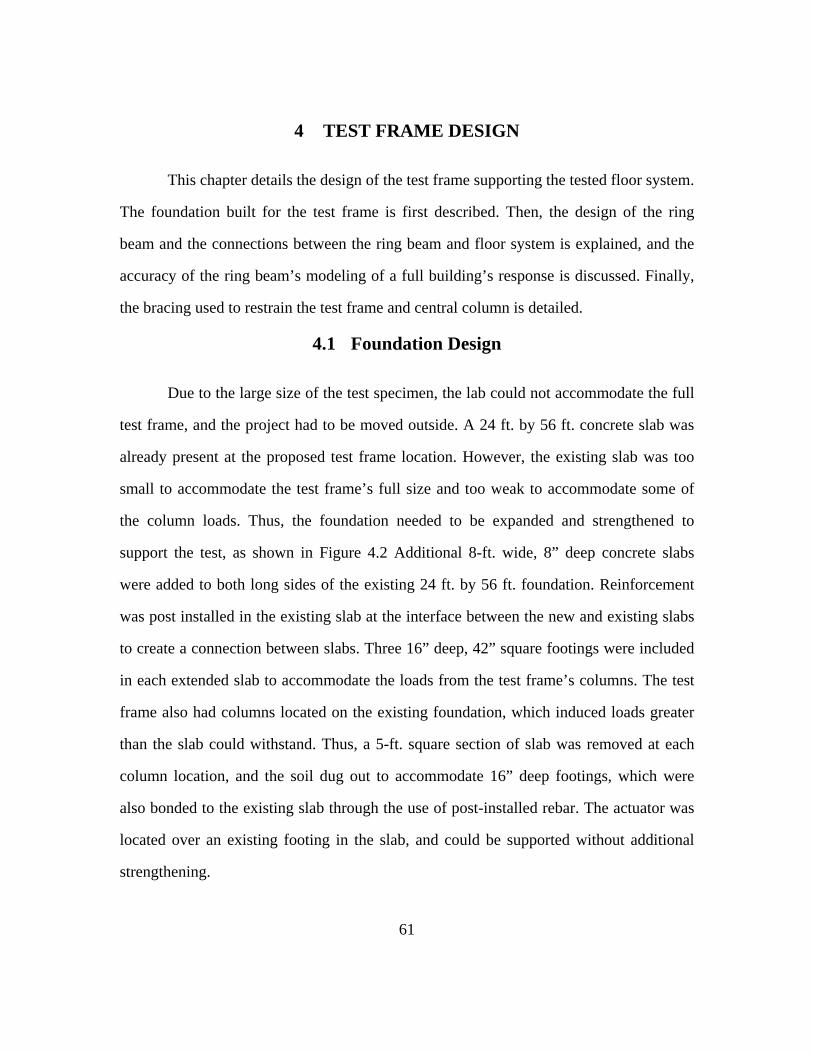
61
4 TEST FRAME DESIGN
This chapter details the design of the test frame supporting the tested floor system.
The foundation built for the test frame is first described. Then, the design of the ring
beam and the connections between the ring beam and floor system is explained, and the
accuracy of the ring beam’s modeling of a full building’s response is discussed. Finally,
the bracing used to restrain the test frame and central column is detailed.
4.1 Foundation Design
Due to the large size of the test specimen, the lab could not accommodate the full
test frame, and the project had to be moved outside. A 24 ft. by 56 ft. concrete slab was
already present at the proposed test frame location. However, the existing slab was too
small to accommodate the test frame’s full size and too weak to accommodate some of
the column loads. Thus, the foundation needed to be expanded and strengthened to
support the test, as shown in Figure 4.2 Additional 8-ft. wide, 8” deep concrete slabs
were added to both long sides of the existing 24 ft. by 56 ft. foundation. Reinforcement
was post installed in the existing slab at the interface between the new and existing slabs
to create a connection between slabs. Three 16” deep, 42” square footings were included
in each extended slab to accommodate the loads from the test frame’s columns. The test
frame also had columns located on the existing foundation, which induced loads greater
than the slab could withstand. Thus, a 5-ft. square section of slab was removed at each
column location, and the soil dug out to accommodate 16” deep footings, which were
also bonded to the existing slab through the use of post-installed rebar. The actuator was
located over an existing footing in the slab, and could be supported without additional
strengthening.

restra
beam
close
restra
force
prese
the c
circum
bays
ment
The respo
aint and supp
m around the
ly as possib
aint present
s that will p
ent in compo
collapsing b
mscribing b
is likely u
ioned previo
onse of a fl
port provide
e test specim
ble. The prim
in a full bui
potentially su
osite building
bays, one w
beam. Howe
unnecessary
ously in Cha
4.2 Rin
loor system
ed to it from
men is inten
mary aspect
ilding, which
upport load a
gs has the po
which may
ever, providi
due to the
apter 2.
Figure 4
62
ng Beam D
under colla
m the surroun
nded to sim
t the ring be
h will enabl
after column
otential to pr
not be pra
ing the full
e presence
4-1 Foundat
Design
apse conditi
nding bays o
mulate the ef
eam needs t
e the floor t
n removal. T
rovide a ver
actical to m
l lateral stre
of the “co
tion
ions is depe
of the struct
ffects of thi
to replicate
to develop th
The large flo
ry large later
match accur
ength of the
ompression
endent on th
ture. The rin
is restraint a
is the latera
he membran
or diaphragm
ral strength t
rately with
e surroundin
ring” effec
he
ng
as
al
ne
m
to
a
ng
ct,

63
While the compression ring effect suggests that the system will have sufficient
lateral strength to support the membrane forces placed on it, whether it has sufficient
lateral stiffness is harder to predict. The lateral stiffness of compression rings relative to
fully restrained slabs has not been investigated at depth, and likely depends on a wide
variety of factors which are not fully understood. Tests have shown slabs relying on
compression rings can have less stiff load-deflection relationships than slabs with full
lateral restraint, but have also been observed displaying higher stiffness under certain
conditions (See Figure 2-16) (Brotchie and Holley 1971). Thus, the difference in
response of a system that relies on the compression ring effect, and one that has lateral
restraint is currently unclear.
Additionally, the amount of lateral restraint that would be provided to a damaged
floor in a full structure is difficult to calculate. Depending on the location of the missing
column, there could be many floor bays around the perimeter of the damaged area, or
none (if the lost column is one bay from the building’s edge). Not only is the restraint
dependent on the lost column location, the restraint provided to the floor slab is
dependent on the connection between the floor slab and the surrounding structures, and
thus is reduced by slip between the decking and concrete, as well as deformation of the
shear studs. Thus, many column loss situations will occur on floor slabs that have
significantly less than full lateral restraint at their perimeter.
Testing has been done by a variety of researchers, including Ferrer et al (2006)
and Marimuthu et al (2007) on the slip of composite decking in pull-out tests. While the
observed load-deflection responses varied significantly due to the decking used and shear
span of the test specimen (See Figure 4-2), the stiffnesses were all orders of magnitude
lower than that of the floor diaphragm. Therefore, the lateral restraint of a composite slab
undergoing membrane action is likely controlled primarily by that stiffness, and not the

latera
stiffn
frame
build
shear
be ac
the re
lab p
flexu
from
stiffn
defle
Fig
al restraint
ness provided
e will also b
ding.
In order t
r stud deform
chieved give
estraining be
projects, and
ural stiffness
the beam’s
ness to ensu
ctions. To p
gure 4-2 Loa
provided by
d by the rin
be controlle
to ensure the
mation, the d
n the econom
eam were tw
d freely avai
, the membr
s centerline.
ure that twi
provide this
ad-Slip Relat
y the comp
ng beam is s
ed primarily
e lateral rest
decision was
mic constrai
wo W27x94
ilable for us
rane loads fr
Thus, the b
isting of th
torsional s
tionship of S
64
ression ring
sufficiently l
y by deck sl
traint was c
s made to ch
ints of the pr
and two W2
se. While th
rom the floo
beams also
e beam did
tiffness, the
Steel Deck-C2006)
g or surroun
large, the la
lip, matchin
controlled pr
hoose the stif
roject. The p
27x84 beam
hese beams p
or system wi
needed to h
d not allow
e restraining
Concrete Com
nding floor
ateral restrai
ng the respo
rimarily by d
ffest ring bea
primary w-sh
ms left over f
possess a hi
ill be acting
have signific
w for excess
g beam was
mposite Bon
bays. If th
nt of our te
nse of a rea
deck slip an
am that coul
hapes used i
from previou
igh degree o
eccentricall
cant torsiona
sive in plan
made into
nd (Ferrer
he
st
al
nd
ld
in
us
of
ly
al
ne
a

close
comp
bay,
exper
Analy
slip a
build
curve
failur
slight
the s
agree
overa
progr
d shape, by
pact) to each
The chose
is still (ba
rimentally o
ysis done by
at the perime
ding with one
e (See Figure
re displacem
tly higher ve
significantly
ement betwe
all behavior
ram.
welding full
h side, creatin
en ring beam
ased on exp
bserved stif
y Imperial C
eter suggest
e surroundin
e 4-4). The l
ment of 218 m
ertical stiffn
higher vert
een the two s
closely, w
Figure 4-3
l depth half
ng a large bo
m design, w
pected latera
ffnesses of th
College of Lo
ts that the sy
ng bay on ea
line at 11.4 k
mm. The ana
ness than one
tical restrain
scenarios wo
while still en
Restraining
65
inch plates (
ox section.
while signific
al load dist
he concrete-
ondon, as pa
ystem is com
ach side, and
kN/m^2 ind
alysis sugge
e restrained
nt provided
ould be idea
nsuring sign
g Beam Deta
(chosen to e
cantly more
tribution) se
-steel deck s
art of this pr
mparable in
d has a simil
dicates the fa
ests that the t
by adjacent
by the rin
al, the curren
nificant stren
ail and Const
ensure the be
flexible tha
everal times
shear bond (
roject, incorp
stiffness to
ar overall lo
ailure load at
test prototyp
t floor bays,
ng beam. W
nt test design
ngth to sup
tructed
eam remaine
an a full floo
s stiffer tha
(Ferrer 2006
porating dec
that of a fu
oad-deflectio
t the assume
pe will have
likely due t
While stronge
n matches th
pport the te
ed
or
an
6).
ck
ull
on
ed
a
to
er
he
st

beam
place
the c
accom
expen
latera
small
mom
F
The restra
ms at their c
e was unfeas
connections
mmodate th
nsive connec
al strength to
l. Thus, the c
ment, resultin
igure 4-4 Lo
aining beam
connections.
sible, so the
needed to b
e entire cap
ctions. As th
o the system
connections
ng in a re
oad-Deflectio
’s stiffness i
Due to acc
connections
be attached t
pacity of the
he compressi
, the demand
were design
elatively eco
on Response
66
is based on t
cess issues,
s had to be b
to, designing
e ring beam
ion ring effe
d on the ring
ned to suppo
onomic det
e of Floor SlBays
the assumpti
welding the
bolted. Due
g fully fixed
m resulted in
ect should pr
g beam conn
ort half of th
tail, while
lab with Rin
ion of fixity
e ring beam
to the smal
d connectio
n prohibitive
rovide the m
nection will l
he ring beam
still provid
ng Beam and
between rin
ms together i
ll flange size
ns that coul
ely large an
majority of th
likely be ver
m’s full plasti
ding strengt
d Adjacent
ng
in
es
ld
nd
he
ry
ic
th

signif
Impe
the d
induc
crack
force
needs
direct
conne
ribs o
to dev
caten
ancho
frame
shoul
paral
decki
appro
ficantly in e
rial College)
In additio
decking’s an
ced by the
king occurs v
will need to
s to be firm
tly with mec
ection betwe
of the steel c
velop the ax
nary load tha
ored through
e. In the dir
ld be more
lel to the d
ing. Accord
oximately 28
Figure
excess of th
).
on to the nee
nchorage ne
membrane
very early at
o be transfer
mly attached
chanical or w
een the steel
could be atta
xial capacity
at could be
h the compo
rection perp
than suffici
decking ribs
ding to dec
8” of develo
e 4-5 Restrai
he predicted
ed for the rin
eeded to be
action. As
the perimet
rred almost e
to the test
welded faste
l decking an
ached in this
of the top ri
transferred
osite bond b
pendicular to
ent to ancho
, this bond
ck slip test
opment leng
ining Beam C
67
d demand (b
ng beam to p
strong eno
experiment
ter of the dam
exclusively t
frame. Atta
eners would
d test frame
s way, such
ibs of the dec
to the test f
etween it an
o the deckin
or the decki
must be ac
ts done by
gth is neede
Connection
based on an
provide the n
ough to with
tal tests ha
maged area (
through the
aching the d
likely have
. Additional
a connectio
cking, signif
frame. Instea
nd the concr
ng, the corr
ing to the c
chieved by
y Abdullah
d for the st
Drawing and
nalytical mod
necessary lat
hstand the
ave shown t
(Bailey 2000
steel deckin
decking to th
e resulted in
lly, since on
on would like
ficantly redu
ad the steel
rete above th
rugations of
concrete. In
the emboss
and Easter
eel decking
d Constructe
dels done b
teral strength
lateral force
that concret
0), this latera
ng, and it thu
he ring beam
a very brittl
ly the bottom
ely be unabl
ucing the tota
decking wa
he restrainin
f the deckin
the directio
sments in th
rling (2009
used on th
ed
by
h,
es
te
al
us
m
le
m
le
al
as
ng
ng
on
he
9),
is

proje
lower
of co
ancho
concr
concr
were
paral
threa
concr
(See
bolte
Refer
Fig
ct to develo
r due to the
oncrete arou
ored, enabli
rete could th
rete deck an
designed to
lel to the de
ded rods we
rete deck to
Figure 4-6)
d to the en
rence sourc
gure 4-6 Res
p its full ten
presence of
und the perim
ing the floo
hen be tied t
nd ring beam
o be reusable
ecking, as th
ere connecte
function as
. Along the
nd at each r
ce not found
straining Bea
nsile capacit
f the compre
meter of the
or system t
to the ring b
m. Due to th
e to simplify
he connector
ed to the rin
shear studs,
ring beams
rib, and she
d.Figure 4-7)
am Boundary
68
y (the actua
ession ring e
e test frame
to achieve t
beam throug
he need to re
y demolition
rs needed to
ng beam suc
, while still
s perpendicu
ear studs we
).
y Parallel to
al tensile dem
effect). Addi
e enabled th
the maximu
gh composite
euse the test
between tes
o pass throu
ch that their
allowing ea
ular to the d
ere welded
o Deck Ribs D
mand will lik
ing this add
he steel dec
um catenary
e connectors
t frame, thes
sts. Along th
ugh the entir
r shaft exten
sy removal
decking, 1/4
to those pl
Detail and C
kely be muc
ditional lengt
k to be full
y effect. Th
s between th
se connector
he ring beam
re ring beam
nded into th
after collaps
" plates wer
lates (Error
Constructed
ch
th
ly
he
he
rs
ms
m,
he
se
re
r!

flexu
the c
edges
span
along
overl
mode
suppo
build
action
the ri
poten
fixity
restra
comp
beam
The other
ural restraint
ompression
s. In additio
over the dam
g the perime
loaded, parti
e for the sys
ort was des
ding. That wa
n without th
ing beam, th
ntial for failu
In a full
y to the floor
aining beam
ponents that
m only need
Figure 4-7 R
r behavioral
around the
ring effect
on, the mem
maged colum
ter of the da
icularly the
tem, it is a f
igned to be
ay, it would
he surroundi
he load tran
ure of those b
structure, th
r system by
m must also
attach to the
s to resist t
Restraining B
aspects the
perimeter. T
is dependen
mbrane action
mn will resu
amaged area
smaller seco
failure mech
e significant
be possible
ing structure
sferred to th
beams check
he surroundi
continuity b
provide fle
e ring beam
the moment
Beam BoundCo
69
e ring beam
The vertical
nt on the pr
n that we be
ult in a large
a. This transf
ondary beam
hanism that i
tly more tha
to observe t
e failing firs
he perimeter
ked indirectl
ing floor ba
between adja
xural restrai
have very w
t imposed b
dary Perpenonstructed
needs to sa
restraint is
resence of v
elieve will a
e load being
fer could res
ms. While th
is well unde
an what wo
the connecti
st. With suff
r beams cou
ly.
ays also can
acent bays.
aint to the s
weak flexural
by simple s
ndicular to D
atisfy are the
particularly
vertical supp
allow the flo
g transferred
sult in those
his is an imp
erstood. Thu
ould be pres
ion failure an
ficient instru
uld be calcul
n provide pa
To mimic th
system. How
l behavior. T
hear connec
eck Ribs De
e vertical an
y important a
port along th
oor system t
to the beam
e beams bein
portant failur
s, the vertica
sent in a fu
nd membran
umentation o
lated, and th
artial flexura
his effect, th
wever, all th
Thus, the rin
ctors and th
etail and
nd
as
he
to
ms
ng
re
al
ull
ne
of
he
al
he
he
ng
he

70
moment capacity of the deck under negative moment, both of which are limited. As the
ring beam was designed as a very torsionally stiff closed shape to resist the torsion from
the eccentric in-plane forces, the existing shape has enough torsional strength and
stiffness to be treated as a nearly rigid boundary for the comparatively weak elements
attached to it.
4.3 Additional Design Considerations
As the full gravity load experienced by the entire structure was relatively small,
the load demand on the columns supporting the test frame was minimal. The corner
columns were thus chosen based on the lab’s availability of pre-existing columns that
were at least 20 ft. long, to accommodate the height of the test frame and top bracing.
Thus, surplus W12x58 columns were chosen as the corner supports of the test frame. The
middle columns were chosen specifically for the project. W4x13 columns proved
sufficient to carry the needed mid-span loads from the gravity loads. Cross bracing was
provided on all sides of the structure and along the top plane of the system. Due to the
small vertical loads on the structure, designing these braces to meet the structure’s
expected demands resulted in very small members. Thus the cross-braces were designed
instead to meet a nominal 10 kip lateral load, to ensure the structure had significant
redundancy against stability failures.
The top cross braces, in addition to providing further stability to the structure, also
provided lateral restraint to the central column. In a column loss scenario, the column
below the affected floor system is assumed to be completely destroyed, but the column
above the floor is fully intact, and still attached to the floor above. Thus, the column will
be laterally restrained by the floor above it, and can provide rotational restraint where it
frames into the damaged floor. In the case of the interior column loss, this will likely

71
have minimal effect, as the symmetry of the system should prevent any significant
rotation at the column. However, in the case of the exterior column loss, the rotational
restraint of the column could enable the beam framing into it to develop its full moment
capacity, improving the performance of the system.
In a true building, the top end of the column would be restrained by the shear
stiffness of the full floor diaphragm. Mimicking the full stiffness at the column top would
be prohibitively expensive. However, if the column is sufficiently stiff, it can act as an
effectively rigid boundary to the connection framing into it. The stiffness of the
composite clip angle that frames into the column connection has been minimally
investigated. Liew et al (2003) looked at the behavior of composite partial depth
endplates under positive moment, which deform in a manner similar to web cleat, and
likely have similar stiffness. For connections of similar depth to the ones used in our
setup, the rotational stiffness is more than an order of magnitude less than that of the
stiffness provided to the column by the braces. Therefore, the column should function
effectively as pinned at the top and mirror the restraint provided by a full structure.

72
5 TEST PROCEDURE
This chapter discusses the procedures for testing the collapse capacity of the floor
system in this experimental program. The procedure for simulating column loss is
explained, as well as the procedure for adding additional load to the structure if
necessary. The matrix of proposed tests is then introduced and detailed.
5.1 Actuator Removal
The most commonly used method for evaluating the robustness of a structure is
subjecting the floor system to a sudden loss of a primary member, usually a column.
Thus, the test setup was designed to simulate a column-loss scenario. In a true collapse
event, the “sudden” loss of a column induces significant dynamic effects. For this test
program, however, column support for the floor system was removed gradually by slowly
retracting the actuator that represented the lost column. This was done because of cost
and safety concerns associated with sudden removal of a column in the test specimen.
Since this was one of the first times such a collapse test has been undertaken, the decision
was made to provide for gradual column removal. This allows for more thorough
observations of structural behavior during the column removal process, and also permits
the opportunity to stop the column removal process, should safety concerns arise during
the course of testing. Also, by monitoring the load-deflection response of the structure,
the energy the structure absorbs can be calculated, and an appropriate dynamic
amplification factor can be calculated and applied to the load to estimate the capacity of
the structure under sudden column removal (Dusenberry and Hamburger 2006).
Nonetheless, gradual column removal is a limitation of this test program that must be
considered when interpreting the test results. In the future, similar tests that include
sudden column removal would be useful.

73
In the test specimen, the effect of column loss is simulated by supporting the
central column through a hydraulic actuator. This actuator can then be lowered, removing
the vertical support provided to the floor system. Teflon sheets are placed between the
actuator and central column to minimize any lateral restraint provided to the floor by the
actuator during initial lowering. Because the ductility of the structure is difficult to
predict, the actuator needed to have a very large stroke capacity so it could be fully
retracted to the point where it was no longer supporting the floor system. To the author’s
knowledge, no empirical testing has taken composite floor slabs to failure in this type of
test, but the upper bound deflection limit for traditionally reinforced slabs is often around
15% of the full span (Stevens 2008), corresponding to a deflection of 4-1/2 feet for our
test specimen. To accommodate this high deflection capacity, a three stage telescopic
actuator was used which allowed the floor system to displace seven feet before hitting the
limits of the test frame. The actuator would then collapse into a steel cage erected under
the floor system to protect it from the collapsing structure, so that the slab could be
loaded further if it survives the initial column removal.
5.2 Loading System
For LRFD design of floor systems under gravity load, ASCE 7 (ref) requires a
factored load of 1.D +1.6L, where D is the nominal deal load, and L is the service live
load. However, for the extreme loading conditions of a column loss scenario, UFC
progressive collapse guidelines recommend designing the structure to withstand a gravity
load of 1.2D+0.5L. Given the assumption of 75 psf nominal dead load and 50 psf service
live load used in the design of the structure, this required a total imposed floor load of
115 psf on the test specimen. While the system’s response to the UFC design load is of
importance, determining the full collapse capacity of the structure was also of interest in

74
this research. Thus, the loading system needed to be able to apply additional load in the
event that the structure survived the full removal of the central column. To design the
loading system, an upper limit for this additional load needed to be chosen. Due to the
many unknowns in the behavior of the test specimen, the true collapse load was difficult
to predict, so the decision was made that a reasonable upper bound for capacity was the
full gravity load the structure was designed for. This load, based on the ASCE
requirement of 1.2D+1.6L resulted in a distributed load of 170 psf.
The loading system chosen would need to apply these loads in a reasonably
uniform manner over the floor slab to match the loading assumptions of typical design.
Thus, the loading system needed to be flexible enough to conform to the structure’s
deflected shape, and not simply span over the slab and apply its load primarily to the
floor beams. This uniform distribution needed to be maintained for both the initial load
and the added load after removal of the column. Given access issues of the test specimen,
the most feasible way to add load was through the use of water added on top of the slab.
Given the potential for significant deflection of the slab, if the water was placed into a
large receptacle, it would drift toward the center of the slab, and lead to the load
concentrating in that area. Thus, the elements of the loading system needed to be small to
keep the water uniformly distributed, and enable the flexibility of the loading system.
The design chosen for the loading system was a set of 40”x40” plywood
formworks, with a 6” layer of concrete placed in the bottom of the formworks to impose
the full UFC collapse load on the floor slab. The formworks are 24” tall, and left in place
after the concrete is poured, so that 18” of available space is left over the concrete for
water to be added. 64 vessels were needed to cover the entire floor slab, which would
have been logistically difficult to place individually. To simplify placement, the
reinforcement in the concrete blocks was placed continuously between adjacent buckets,

to tie
betwe
suffic
throu
bubb
allow
is the
study
decki
sheet
most
dama
struct
memb
e them toget
een buckets
cient flexibi
ugh an irriga
lers are des
wing the adde
The behav
e role of cate
ying this dir
ing, as well
ts would req
critical part
aged area. Th
ture, can g
brane respo
ther in grou
s, to maintai
lity to defle
ation system
signed to a
ed load to be
vior we belie
enary action
rectly is ver
as its comp
quire a prohi
t of the cate
his response
ive a very
nse. Additio
ups of four.
in the unifo
ect with the
which inclu
add water to
e accurately
5.3 Ins
eve to be mo
n in the floor
ry difficult.
lex geometr
ibitive amou
enary respon
e, if examine
accurate e
onally, the l
Figure 5-1
75
This also p
ormity of lo
floor slab.
udes a “bubb
o each indiv
calculated (
strumenta
ost significan
r system’s u
Given the v
ry, an accura
unt of instru
nse is the fo
ed in conjun
estimate of
load the flo
Irrigation S
provided for
oad, while s
To add load
bler” nozzle
vidual buck
See Figure 5
ation
ant to the resp
ultimate load
very large s
ate picture o
umentation t
orce it exerts
nction with th
the load su
oor system e
System
r a consisten
still allowin
d, water wa
over each b
ket at a pre
5-1).
ponse of the
d capacity. U
surface area
of the strain
to achieve. H
s on the per
he displaced
upported by
exerts on th
nt 6” spacin
g the system
as be pumpe
bucket. Thes
escribed rate
e floor system
Unfortunately
a of the stee
across all th
However, th
rimeter of th
d shape of th
y the floor
he rest of th
ng
m
ed
se
e,
m
y,
el
he
he
he
he
’s
he

struct
surro
typic
from
beam
place
beam
determ
isolat
capac
displa
centr
of the
Figur
ture will sug
unding stru
al composite
the floor sy
ms and their
ed on the top
m, so the resp
mine the ax
ted and studi
The overa
city of the s
acement the
al column c
e beams, cau
re 5-3a). If
ggest whethe
ucture, or w
e constructio
ystem will pr
connections
p and bottom
ponse could
xial force pr
ied.
all displacem
structure’s m
floor system
onnections i
using the flo
the connect
F
er the catena
whether the
on. Finally,
rovide an ind
s as catenar
m of the ring
d be monitor
resent in it,
ment of the f
membrane re
m, and the s
is low, their
oor system t
tions are stif
Figure 5-2 In
76
ary response
compression
the demand
dication of t
ry action is
beam’s flan
red. Addition
so the axia
floor system
esponse is h
shape of the
r rotation wi
to deform as
ffer, they m
nstrumentati
imposes a s
n ring effec
d placed on t
the demands
developed.
nges at the m
nally, the gi
al contributi
m is also imp
heavily depe
deflected sl
ill significan
s a group of
may cause th
ion Plan
significant d
ct can be co
the surround
s placed on t
Thus, strain
mid and end p
irder was str
on of the d
portant to m
endent on th
lab. If the st
ntly exceed t
f largely rigi
he system to
emand on th
ounted on i
ding structur
the secondar
n gages wer
points of eac
rain gaged t
deck could b
monitor, as th
he maximum
tiffness of th
the deflectio
id plates (Se
o deflect in
he
in
re
ry
re
ch
to
be
he
m
he
on
ee
a

shape
gover
determ
used
ends
the fl
occur
shear
impa
dissip
the d
To st
attach
colum
rotati
mom
F
e more simil
rn the rotatio
mines the e
to measure
of the beam
loor system.
rs between t
r connection
Additiona
ct of dynam
pate in a tru
ductility can
tudy the resp
hed to moni
mn connecti
ion. The gir
ment in the b
Figure 5-3 F
lar to that o
on at the end
ffectiveness
vertical dis
ms framing in
String pots
the central c
s.
ally, the duc
ic amplificat
ue “sudden c
be determin
ponse of the
itor the hor
ion, allowin
rder flanges
eam. By stu
Floor System
of a long bea
ds of the slab
of the cate
placement o
nto the centr
were also at
column and
ctility of the
tion on the s
column loss”
ned by comp
e beam and g
izontal disp
ng measurem
s were also
udying the r
m Displacing
77
am (See Fig
b, which (alo
nary action.
of all floor b
ral column, t
ttached to th
floor system
system will
structure, and
” scenario. F
paring the ap
girder conne
placement at
ment of the
strain gage
esponse of t
as (a) Rigid
gure 5-3b). T
ong with the
. Thus, large
beams at the
to capture th
he central col
m, particular
l play a larg
d how much
For the deck
pplied load
ections to th
t the top an
axial displ
ed at the m
the connecti
d Plates and (
This deflecte
maximum d
e stroke stri
eir mid poin
he full displa
lumn, to det
rly after the
ge role in det
h energy it ca
king’s caten
to the overa
he column, st
nd bottom fl
lacement as
mid-point to
ions to the c
(b) Flexural
ed shape wi
displacemen
ing pots wer
nts and at th
aced shape o
termine if sli
failure of th
termining th
an effectivel
nary response
all deflection
tring pots ar
lange at eac
s well as th
estimate th
collapse load
Shapes
ill
nt)
re
he
of
ip
he
he
ly
e,
n.
re
ch
he
he
d,

the st
determ
collap
on th
simul
system
an int
exter
tiffness of th
mined, givin
pse conditio
The abilit
he boundary
lation of mu
m responds
terior colum
ior column l
he connectio
ng further in
ns.
ty of a system
conditions i
ultiple colum
to collapse e
mn loss, with
loss with onl
Figure 5
ons (both axi
nsight into th
5.4 T
m to carry lo
imposed on
mn loss scena
events. The
the full 2 ba
ly one half o
5-4 String Po
78
ial and rotat
he strength a
Test Matr
oad through
it. Thus, the
arios to bett
proposed tes
ay by 2 bay
of the floor c
ot Layout at
tional) and th
and ductility
rix
catenary ac
e proposed t
ter understan
st matrix inc
floor cast, a
constructed o
Center Colu
he point of f
y of these el
ction is heavi
test program
nd how a co
cludes three
and three tes
on the test fr
umn
failure can b
ements unde
ily dependen
m includes th
mposite floo
tests done o
sts done on a
rame.
be
er
nt
he
or
on
an

colum
under
evalu
condi
ring,
been
direct
exert
comp
mode
on th
deck
does
The first
mn (i.e. with
r the ideal
uation of so
itions in the
while it has
studied in h
tions, the ef
ed by the m
pletion of th
els the behav
he restraining
will crack u
not allow fo
5
series of pr
h a floor slab
conditions
ome of the
test frame si
been observ
heavily ortho
ffectiveness
membrane o
he first test,
vior of com
g beam will
under minim
or torsional d
Figure 5-5
5.5 Interi
roposed test
b in all bays s
for membra
test assum
imulate thos
ved in many
otropic slabs
of the comp
on the restr
to determin
mposite floor
l need to be
mal negative
deflections th
5 Interior and
79
ior Colum
ts are intend
surrounding
ane action.
mptions, in
se present in
y experiment
. Due to the
pression ring
aining beam
ne how accu
decks. Add
e studied, to
moment is
hat would no
d Exterior C
mn Loss
ded to study
the column
In addition
particular h
an actual str
ts, has not (to
different de
g could be r
m will need
urately the
ditionally, th
o ensure that
valid, and t
ot be present
Column Test
y the loss o
), to evaluat
n, these test
how well t
ructure. The
o the author
eck propertie
educed. The
d to be stud
compression
he torsional
t the assump
that the rest
t in a full str
Setup
of an interio
te its respons
ts will allow
the boundar
e compressio
rs knowledge
es in differen
e lateral forc
died after th
n ring theor
force exerte
ption that th
training beam
ructure.
or
se
w
ry
on
e)
nt
ce
he
ry
ed
he
m

80
The first proposed test is on the unmodified building design, with no
modifications made to improve robustness. The results of this test will significantly
improve understanding of the robustness of typical composite construction. In particular,
the failure sequence observed (if any) will indicate the ductility of the system, and the
components most critical to the performance of the structure. Using the results of this
test, a new design will be created, consisting of revised details to improve the
performance of the critical components, and hopefully increase the robustness of the
structure. This new design will then be constructed and tested under a column loss
scenario, to determine if the collapse performance of the structure can be improved. A
third interior column test is also planned, where the central column will first be lifted,
forcing the floor system to deflect upward. In the case of an interior column loss resulting
from an explosion, the pressure of the blast can produce an initial uplift on the system,
before the blast dissipates and the floor system deflects downward. This uplift has the
potential to damage some components of the structure (particularly the concrete around
the column), leading to a possible loss of stiffness and strength in the later response of the
structure. By applying an initial upward force to the central column before removing it,
we can simulate this damage and see whether it plays a significant role in the final load
carrying capacity of the structure.
5.6 Exterior Column Loss
The second series of tests will simulate the loss of an exterior column. Without
the presence of an undamaged building section on all sides of the slab, the system’s
ability to form a two-way membrane is likely to be heavily compromised. In this
scenario, the slab’s response will be a primarily one-way membrane spanning between
the opposite undamaged sides. Because of this, and because of the orthotropic nature of

81
the composite decking, the orientation of the decking can have a significant effect on the
ability of the slab to carry collapse loads. Thus, specimens will be tested with the decking
ribs parallel to the exterior wall, and with decking ribs perpendicular to the exterior wall.
In addition to the reduced load carrying capacity of the slab when forming a one-
way membrane, there is an additional concern of load redistribution to the undamaged
members. As stated previously, the flexural members around the perimeter of the
damaged area experience significant increases in load in collapse scenarios, which could
lead to their failure. This increase is even more significant in the case of one-way
membrane action, as fewer flexural members are mobilized to carry the redistributed
load. However, there is the possibility for the slab to still be able to form a two-way
membrane even without the presence of an undamaged section on one side of the affected
area. Analysis done by Stevens (2008) showed that the placement of a peripheral tie
along the perimeter of the structure could enable the formation of membrane forces in
both directions, though the membrane action is larger in the direction that provides lateral
restraint (See Figure 2-6). This could reduce the increased demand on the surrounding
structure, improving its robustness, though the effect may be small. The peripheral ties
examined in the study were also subjected to very large tensile forces, likely larger than
those that could be supported by existing composite construction.
The third proposed exterior column loss test will examine whether this behavior is
something that can be readily achieved in composite construction. Depending on the
results of the earlier tests, a new detail will be created to allow the structure to carry a
significant peripheral tie force, allowing the formation of a two-way membrane. The
ability of this tie force to carry tensile loads, as well as the effect of the tie force on the
floor system’s capacity and the demand on the surrounding structure will be evaluated for
their potential to improve the building’s robustness.

82
6 CONSTRUCTION OF TEST FRAME AND FIRST TEST SPECIMEN
This chapter discusses the construction of the test set-up and the first interior
column loss test specimen. The expansion of the foundation and the revisions to the test
frame after expansion are detailed. Construction of the loading system is explained. The
erection of the test frame and specimen is discussed, and the casting of the concrete floor
slab is shown.
6.1 Foundation Pour
The test frame was constructed outside of the University of Texas at Austin
Ferguson Laboratory. The test frame was constructed outside of the laboratory, as space
constraints precluded constructing the test frame inside of the laboratory. The area of
outside of the laboratory chosen for the test frame construction already had an existing
slab on grade that could be used as the foundation for the test setup. However, the
existing foundation in place at the location of the test set-up lacked the size and strength
to support the columns of the test frame. Thus, the foundation needed to be expanded,
and footings needed to be added at the locations of all test columns. For the middle
columns supporting the long restraining beam, there was an existing concrete slab under
them, which did not have the capacity to withstand the expected gravity loads that would
be imposed at that location. Thus, the existing slab needed to be removed to allow the
pouring of a stronger footing under the column. Due to problems during placement of
anchor rods in the expanded foundation, there was less exposed length of anchor rod than
initially designed. This meant that the W4x13 columns could not be attached directly to
the foundation, as there would not be sufficient threads in the anchor rods to secure them.
Couplers were added to the existing anchor rods, and additional threaded rods were

conne
short
colum
the sl
Addit
locati
spaci
frame
geom
with
were
ected to the
ened slightly
mn base plat
lab and base
tionally, dur
ion due to i
ing between
e and speci
metry.
The loadi
a concrete s
constructed
Figure 6
m, so that t
y to allow f
te did not be
e plate to pr
ring placeme
nterference
footings alo
imen were
ing system f
slab at the b
d of 23/32” p
6-1 Coupler
the columns
for this addi
ear directly o
revent exces
ent, some an
with the reb
ong the add
shortened
6.2 Lo
for the test
bottom, and
plywood sh
Attachment
83
s could be a
itional conne
on the slab,
ss flexibility
nchor rods w
bar in the sl
ed slab strip
to ensure c
oading Sys
setup was m
room abov
eets to have
t to Accomm
attached to t
ection length
so spacer pl
y due to dist
ere unable to
lab. This res
ps. The relev
compatibility
stem
made of larg
ve it to add
e outside dim
modate Short
those. The c
th. Due to th
lates were ad
tortion of th
o be placed
sulted in a s
vant membe
y with the
ge square ply
18” of wate
mensions of
t Anchor Ro
columns wer
his detail, th
dded betwee
he base plate
in the desire
slightly lowe
ers of the te
new ancho
ywood boxe
er. The boxe
f 40” x 40”
ds
re
he
en
e.
ed
er
st
or
es
es
x

84
24”. The bottom sheet was attached to the walls with 7-2” exterior screws along each
side. The walls of the boxes would have to stand significant outward pressure from the
water added during testing, and due to the small thickness of the plywood, end screwing
between sheets was unlikely to be able to sustain the resultant load. Thus, 2-ft. long
sections of 2x2 dimensioned lumber were added at each corner, and the walls were
attached to those pieces with 6 2” long exterior screws at each end. To further reinforce
the connections, and seal the boxes, silicone caulking was applied along all seams
between pieces of the formwork. Though constructed of exterior grade plywood, there
was concern that the boxes (as they would be left outside when not in use) would degrade
if rainwater was trapped in them for extended periods of time. Thus, 6 mil plastic
sheeting was used to line the interiors of each bucket, to protect the plywood from the
elements. Unfortunately, the plastic sheeting proved very sensitive to UV radiation, and
broke down rapidly under sun exposure, removing the benefit to the boxes.
Five 7/16” holes were drilled into each wall of the formwork at an 8” spacing to
allow the passage of #3 bars into the formwork, to tie the boxes together in groups of
four, with a 6” spacing between all boxes. The reinforcement chosen was the minimum to
resist shrinkage and cracking of the concrete (to improve water retention ability of the
system), while allowing the maximum flexibility of the system, so it could deform in
tandem with the collapsing floor slab. Additional #2 bars were bent into 180⁰ hooks with
a 4” radius, and placed through the existing drilled holes such that 6” of rebar protruded
from the boxes, ensuring that neighboring groups of buckets still maintained the 6”
spacing between boxes. 1/2" steel tendons were placed that spanned from the center of
one box to the center of the adjacent box, to allow easy movement by either the lab
forklift or a crane during placement of the boxes. Finally, 6” of concrete was added to
each bucket to achieve the desired floor load. Due to uncertainty in exact placement of

concr
asses
attach
of the
woul
stabil
impa
place
were
restra
The r
rete, the bo
sment of the
The colum
hment of the
e restraining
d be in typ
lity purposes
ct on the fi
ed on the gus
left only sn
aining beam
restraining b
oxes were e
e floor load t
mns were a
e restraining
g beam, the
ical constru
s, any additio
nal behavio
sset connect
nug-tight. A
and the col
eam’s conne
Figur
each weighe
they imposed
6.3
all erected an
g beam to th
plumbness
uction. Due
onal out-of-p
or of the fra
tions to the c
laser range
lumns were
ections were
re 6-2 Const
85
ed after cas
d could be c
Test Fram
nd plumbed
e columns a
of the colum
to the signi
plumbness in
ame during t
corner colum
finder was u
shimmed u
e then fully ti
tructed Load
sting was c
calculated.
me
d. Due to th
and the attac
mn was not
ificant over
n the column
testing. The
mns and bolt
used to mea
until the ring
ightened wh
ding Boxes
complete so
he tight toler
chments betw
enforced as
rdesign of th
ns should ha
e restraining
ted together,
asure the dia
g beam was
hile in this co
o an accurat
rances of th
ween section
s strictly as
he braces fo
ave negligibl
g beams wer
, but the bolt
agonals of th
fully square
onfiguration
te
he
ns
it
or
le
re
ts
he
e.
.

centr
sides
adjus
along
beam
held b
the b
girde
the b
were
could
with
The perim
al column b
and the to
stment durin
g the west w
ms. The centr
by the bracin
bottom by an
rs and floor
eams were a
adjusted thr
d be plumbe
a shorter fr
meter top c
bracing chor
op of the re
ng placemen
wall was left
ral column o
ng chords at
n existing fr
beams were
attached and
rough tighten
ed. Next, th
rame, allowi
Figur
hords were
rds attached
estraining fr
nt of the cen
disconnecte
of the specim
t the top of t
rame present
e attached to
d laterally bra
ning of the h
e frame sup
ing sufficien
re 6-3 Erectio
86
then attach
to them. Th
rame. The t
ntral column
d to allow a
men was then
the test fram
t at the lab
o the restrain
acing the co
horizontal cr
pporting the
nt clearance
on of Restra
hed to the c
he cross bra
top braces w
n, and the lo
access for th
n raised into
me. The colum
to within 1”
ning beam a
olumn, the to
ross braces s
column wa
for screw j
aining Beam
corner colum
aces were at
were left lo
ower south
he forklift to
place so tha
mn was then
” of its fina
and central c
op column br
so that the ce
as removed
jacks to be
s
mns, and th
ttached to a
oose to allow
bracing stra
move furthe
at the top wa
n supported a
al height. Th
column. Onc
racing chord
entral colum
and replace
placed unde
he
all
w
ap
er
as
at
he
ce
ds
mn
ed
er

each
heigh
beam frami
ht.
Fi
ng into the
igure 6-4 Te
column, so
emporary Fra
87
the column
ame Support
could be ra
ting Central
aised to its p
Column
precise desiggn

were
disco
along
instal
and f
cover
mode
perim
Once the
laid and c
ontinuities. O
g all beams a
lled in mem
floor beams.
r plates, pilo
el of tek scre
meter of the
flexural me
cut in place
Once all dec
and side lap
mbers up to .
For the atta
ot holes of
ew. Once th
specimen t
Figure 6-
6.4 F
embers were
e to fit aro
cking sheets
ps. All tek sc
345” thick,
achment betw
13/64” were
e decking w
to serve as
-5 Screw Jac
88
Floor Syste
e all in plac
ound the ce
s were in p
crews were s
which accom
ween the dec
e drilled to a
was in place,
the perimet
cks Supportin
em
ce, the deck
entral colum
place, #10 te
special teks/
mmodated t
cking and rin
allow easier
18 gage an
ter formwor
ng Floor Sys
king was laid
mn and oth
ek screws w
/2 screws, d
the flanges o
ng beam, wh
r installation
ngles were at
rk for the co
stem
d. The sheet
her necessar
were installe
designed to b
of our girder
hich had 1/2
n of the sam
ttached to th
oncrete pou
ts
ry
ed
be
rs
2”
me
he
ur.

These
to the
to en
to the
with
angle
attach
the u
Fig
e angles wer
e deck ribs.
sure the stud
e deck ribs,
tek screws a
e, and place
hed with tek
se of sprayab
gure 6-6 Slab
re installed w
This increas
ds could dev
the angle w
at a 12” spac
ed at all ope
k screws. Any
ble foam ins
b Closures (a
with a 2” ove
sed the lengt
velop their fu
was installed
cing. Pour sto
en ends of t
y observable
sulation.
a) Parallel to
89
erhang along
th of concret
ull capacity.
with no ove
op closures w
the decking
e gaps remai
o Deck Ribs
g the restrain
te the shear
Along the r
erlap. Both f
were created
g ribs to sto
ining in the f
and (b) Perp
ning beams p
studs could
restraining b
formworks w
d out of the s
op concrete
floor were se
pendicular to
perpendicula
d bear agains
beams paralle
were attache
same 18 gag
seepage, an
ealed throug
o Deck Ribs
ar
st,
el
ed
ge
nd
gh

direct
reinfo
were
reinfo
bars w
to the
was p
and 9
bendi
exten
reinfo
lower
The weld
tion of deck
orcement. O
placed unde
orcement rol
were placed
e deck ribs a
placed aroun
9” from the
ing of the r
nded higher
orcement, th
ring the max
ded wire rein
k span. Each
Once the wel
er the reinfo
lls were tied
d at 12” spac
and tied to th
nd the perim
edge perpen
reinforcemen
than the ex
he chairs we
ximum heigh
Figure 6-7 P
nforcement w
roll was lai
ded wire wa
orcement at
d to each oth
cing over the
he welded wi
meter of the fl
ndicular to th
nt between p
xpected 4” m
ere manually
ht of the reba
Pour Stop Cl
90
was laid in
id overlappin
as placed, 4-
4-ft. spacing
her at 3-ft. sp
e girders and
ire reinforce
floor at 3” fro
he deck ribs
points of su
maximum h
y shortened
ar to a more
losures and I
5-ft. wide r
ng the previ
-ft. long 3-1/
g. Once the
pacing. Add
d along the r
ment (See F
om the edge
s (Figure 6-8
upport, sectio
height. To im
to an appro
appropriate
Insulation S
rolls perpend
ous roll by o
/2” tall cont
chairs were
ditional 3-ft.
restraining b
Figure 6-8). A
e parallel to
8 and Figure
ons of the r
mprove the
oximate heig
position.
ealing
dicular to th
one square o
tinuous chair
e in place, th
lengths of #
beams paralle
A final #3 ba
the deck rib
e 6-9). Due t
reinforcemen
cover of th
ght of 3-1/4”
he
of
rs
he
#3
el
ar
s,
to
nt
he
”,

FFigure 6-8 RReinforcemennt Layout al
91
ong Restrainning Beam PParallel to Deck Ribs
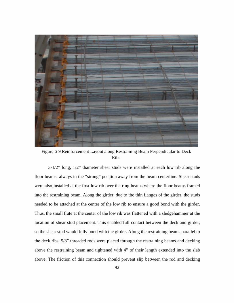
floor
were
into t
neede
Thus
locati
so the
the d
above
above
F
3-1/2” lon
beams, alw
also installe
the restrainin
ed to be atta
, the small fl
ion of shear
e shear stud
eck ribs, 5/8
e the restrai
e. The fricti
Figure 6-9 Re
ng, 1/2” dia
ays in the “s
ed at the firs
ng beam. Al
ached at the
flute at the ce
r stud placem
would fully
8” threaded r
ning beam a
ion of this c
einforcemen
ameter shear
strong” posi
st low rib ov
ong the gird
center of th
enter of the l
ment. This en
bond with t
rods were pl
and tightene
connection sh
nt Layout alo
92
r studs were
ition away fr
ver the ring b
der, due to th
he low rib to
low rib was
nabled full c
he girder. A
laced throug
ed with 4” o
hould preve
ong RestrainiRibs
e installed a
rom the beam
beams wher
he thin flang
o ensure a go
flattened wi
contact betw
Along the rest
gh the restra
of their lengt
ent slip betw
ing Beam Pe
at each low
m centerline
re the floor b
ges of the gir
ood bond wi
ith a sledgeh
ween the dec
training beam
aining beams
th extended
ween the rod
erpendicular
rib along th
e. Shear stud
beams frame
rder, the stud
ith the girde
hammer at th
ck and girde
ms parallel t
s and deckin
into the sla
d and deckin
r to Deck
he
ds
ed
ds
er.
he
er,
to
ng
ab
ng

93
and function approximately as a stud weld. An additional nut was attached to the
threaded rods and positioned at 3-1/2” above the decking, to function as the “head” of a
shear stud and allow the threaded rod to develop composite action with the concrete slab
in a comparable fashion (See Figure 6-8). Along the restraining beams perpendicular to
the deck ribs, 4” wide, 10” long 1/4” plates were attached at each low rib to the
restraining beam with a 5/8” bolt. The decking was cut back in areas where it extended to
the location of this bolt, to ensure consistency in boundary conditions along the length.
Shear studs were then attached to this plate through the decking (See Figure 6-9).
6.5 Concrete Casting
Before pouring of the concrete, two potential areas of instability were noted in the
test frame. The gusset plates used in the restraining beam to column connections, due to
their large size, had the potential to buckle out of plane, and lose their ability to support
the floor system. Thus, 2 1/2” plates, 10” wide by 14” long, were welded to the ends of
the gusset plates, to serve as a diaphragm tying the plates together (See Figure 6-10a). As
an additional concern, the lateral cross bracing parallel to the deck ribs framed into the
center of the restraining beam cover plate, as did the W4x13 column that provided the
needed vertical support to make the bracing system functional. Due to the relatively thin
cover plate used, and the large distance between the flanges of the restraining beam, the
out of plane flexibility of the cover plates significantly reduced the stiffness of the
bracing system as a whole. Thus, 2 5” wide, 3/4” plates were welded to the bottom side
of the restraining beam between the column and cross brace connections to serve as
transverse stiffeners, preventing local distortions, and improving the effectiveness of the
bracing system (See Figure 6-10b).
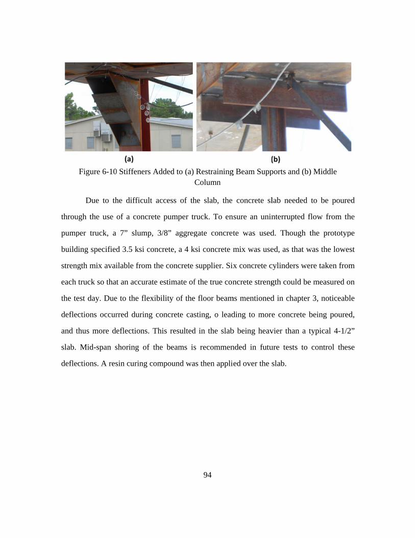
throu
pump
build
streng
each
the te
defle
and t
slab.
defle
Due to th
ugh the use
per truck, a
ding specified
gth mix avai
truck so that
est day. Due
ctions occur
thus more de
Mid-span s
ctions. A res
Figure 6-10
he difficult
of a concret
7” slump,
d 3.5 ksi con
ilable from t
t an accurate
e to the flexi
rred during
eflections. T
shoring of t
sin curing co
0 Stiffeners A
access of th
te pumper tr
3/8” aggreg
ncrete, a 4 k
the concrete
e estimate of
ibility of the
concrete cas
This resulted
the beams is
ompound wa
Added to (a)
94
he slab, the
ruck. To en
gate concret
ksi concrete m
supplier. Six
f the true con
e floor beam
sting, o lead
d in the slab
s recommen
as then appli
RestrainingColumn
concrete sl
nsure an unin
te was used
mix was use
x concrete c
ncrete streng
ms mentioned
ding to more
b being heav
nded in futu
ed over the s
g Beam Supp
lab needed
nterrupted f
d. Though t
ed, as that w
cylinders we
gth could be
d in chapter
e concrete b
vier than a t
ure tests to
slab.
ports and (b)
to be poure
flow from th
the prototyp
was the lowe
re taken from
e measured o
3, noticeabl
being poured
typical 4-1/2
control thes
) Middle
ed
he
pe
st
m
on
le
d,
2”
se

95
7 SUMMARY AND CONCLUSIONS
7.1 Summary of Work
This thesis has detailed the design and construction of a test program for
evaluating the response of steel framed composite buildings to a column loss scenario. A
prototype building was designed to match current construction practice and test
specimens were designed based on that prototype building, and scaled down to
accommodate the constraints of the test setup. A test frame was designed and constructed
to simulate the boundary conditions that would be provided by the neighboring bays of a
full structure. A loading system and protocol was detailed to simulate the removal of a
column while providing gravity load, with the option to provide further uniform gravity
loading if necessary to cause failure of the test specimen. As this thesis does not cover the
results of the experimental testing, it is difficult to draw definitive conclusions on the
accuracy of the test program, however, preliminary observations based on literature
review and analysis are summarized below.
7.2 Accuracy of Boundary Conditions
One significant assumption made in the design of this test program was that the
response of a building to a column loss scenario could be modeled accurately looking at
an isolated section of the building, with the effect of neighboring bays simulated by the
presence of a heavy restraining beam around the specimen’s perimeter. This assumption
introduces significant uncertainty into the test program, both in the ability of the ring
beam to provide sufficient restraint, and in the restraint that should be present in a full

96
structure. Depending on the location of the lost column, and the layout of the structure,
the number of neighboring bays around the damaged area can vary widely, changing the
restraint provided to the affected floor. Additionally, the stiffness of the lateral restraint
provided by the neighboring bays could be significantly reduced by local deformation
(particularly deformation in the shear studs and bond slip between the concrete and
composite deck), although there is insufficient experimental data to definitively conclude
this. Thus, the necessary lateral restraint that must be provided by a perimeter beam to
accurately simulate the response of the rest of the structure is not precisely known at this
point. It is the opinion of the author that providing a restraining beam of high flexural and
torsional stiffness (such as the one used in this research) will mirror the response of an
actual structure with reasonable accuracy, as both responses will be dominated by local
flexibility of the shear studs and decking. Testing of a larger section of building, with
neighboring bays present is likely necessary to confirm this assumption.
7.3 Effect of Scale on Results
While the test specimens constructed as part of this research program are of a
large size, many of the components are smaller than what would typically be seen in
modern construction. The precise effect of this scaling down is unknown. The gravity
connections, (both shear tab and clip angle) are made of thinner plates or angles than are
commonly used, and are less deep than common connections. Both of these changes have
been shown in other research to significantly increase the ductility of the connection,
possibly allowing the specimens tested in this project to achieve greater maximum
deflections than could be counted on in a larger span structure. The floor slab is also
made of thinner deck than is often used, and has slightly smaller spans. However,
previous testing on tie forces suggests that this scaling has limited effect on the ductility

97
of the system, with slabs of varying reinforcement ratios and spans all achieving similar
rotations before failure. Unfortunately this testing has been limited primarily to
reinforced concrete slabs, and its applicability to composite slabs is not known.
Nevertheless, it is the opinion of the author that the floor slab used in this test will behave
in a manner similar to the larger span floor slabs typically seen in practice, albeit with the
magnitude of the tie forces scaled down due to the smaller area of steel in the thin deck.
The applicability of this test to larger span structures thus will likely depend on which
system dominates the response. If the specimen’s robustness is provided primarily by the
flexural system (beams, girders and shear connections), the increased ductility of the
smaller connections may lead to an over-prediction in strength if extrapolated to other
structures. If the response is dominated by the floor slab, then the small scale will have
less impact on the results, and the response of the test specimen will likely be similar to
that of a larger span structure, allowing us to draw reasonable conclusions as to the ability
of steel framed composite building to withstand column loss.

98
APPENDIX A: TEST SPECIMEN AND FRAME DRAWINGS

99

100

101

102

103

104

105

106

107
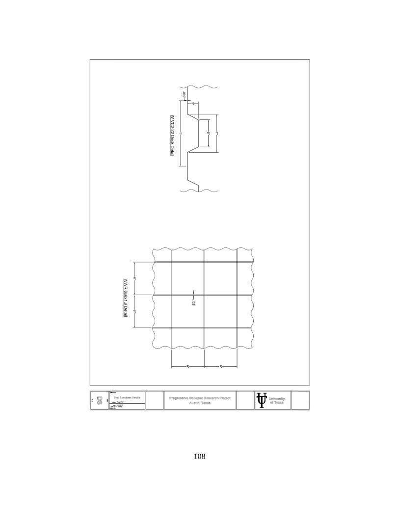
108

109

110

111

Figure A
-14 Test F
rame D
etails-Central A
ctuator Support, L
ateral Brace to R
ing Beam
Connection
F
igureA
-14T
estFram
eD
etails-CentralA
ctuatorS
upportL
ateralBrace
toR
ingB
eamC
onnection
112

113

114

115

116

117

118
APPENDIX B: PROTOTYPE BUILDING PLANS
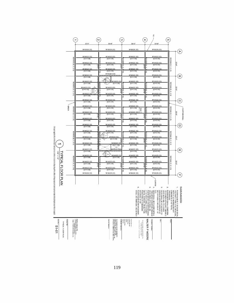
119

120

121

122

123

124

125

126

127

128

129

130
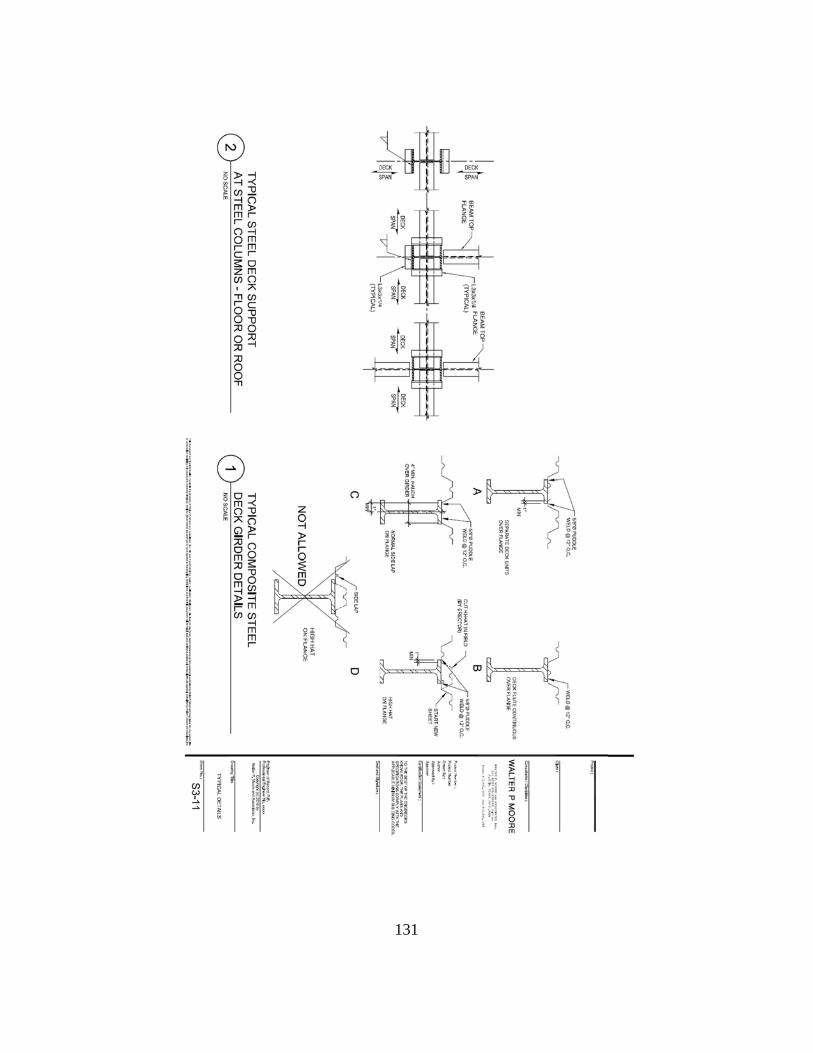
131

Figure B
-14 Prototype B
uilding-Brace C
onnection Detail
Figure
B-14
Prototype
Building-B
raceC
onnectionD
etail
132

133
WORKS CITED
Abdullah, Redzuan, and W. Samuel Easterling. "New Evaluation and Modeling Procedure for Horizontal Shear Bond in Composite Slabs." Journal of Constructional Steel Research 65.4 (2009): 891-99 Abolmaali, A., A.R. Kukreti, and H. Razavi. "Hysteresis Behavior of Semi-rigid Double Web Angle Steel Connections." Journal of Constructional Steel Research 59.8 (2003): 1057-082
ACI. Building Code Requirements for Structural Concrete: (ACI 318-08); and Commentary (ACI 318R-08). Farmington Hills, MI: American Concrete Institute, 2008. Alashker, Yasser, Sherif El-Tawil, and Fahim Sadek. "Progressive Collapse Resistance of Steel-Concrete Composite Floors." Journal of Structural Engineering 136.10 (2010): 1187-196
AISC. Steel Construction Manual. Chicago, IL: American Institute of Steel Construction, 2005 Thirteenth Edition American Institute of Steel Construction. Steel Design Guide 3. Serviceability Considerations for Steel Buildings. 2003. Second Edition American Institute of Steel Construction. Steel Design Guide 11. Floor Vibrations Due to Human Activity. 1997. ASCE. Minimum Design Loads for Buildings and Other Structures. ASCE/SEI 7-10 Reston, VA: American Society of Civil Engineers/Structural Engineering Institute, 2010. Ashcraft, Douglas. “Steel Deck Design, Specifications, and Details.” Engineering Skills and Development Program. Nov. 2006. Astaneh, Abolhassan, Marwan N. Nader, and Lincoln Malik. "Cyclic Behavior of Double Angle Connections." Journal of Structural Engineering 115.5 (1989): 1101-118.
Astaneh-Asl, Abolhassan, Brant Jones, Yongkuan Zhao, Ricky Hwa, David McCallem and Charles Noble (2001), “Progressive Collapse Resistance of Steel Building Floors”, Report No. UCB/CEE-Steel-2001/03, Department of Civil and Environmental Engineering, University of California, Berkeley.
Bailey, Colin G. "Membrane Action of Unrestrained Lightly Reinforced Concrete Slabs at Large Displacements." Engineering Structures 23.5 (2001): 470-83

134
Brotchie, John F., M.J. Holley. (1971) “Membrane Action in Slabs.” American Concrete Institute Publication SP-30-16. 343-355.
Dusenberry, Donald O., and Ronald O. Hamburger. "Practical Means for Energy-Based Analyses of Disproportionate Collapse Potential." Journal of Performance of Constructed Facilities 20.4 (2006): 336-48 DoD (2009). UFC 4-023-03: Design of Buildings to Resist Progressive Collapse, Department of Defense, Washington, DC.
Ferrer, Miquel, Frederic Marimon, and Michel Crisinel. "Designing Cold-formed Steel Sheets for Composite Slabs: An Experimentally Validated FEM Approach to Slip Failure Mechanics." Thin-Walled Structures 44.12 (2006): 1261-271 Fleischman, R. B., Chasten, C. P., Lu, L. W., & Driscoll, G. C. (1991). Top-and-seat-angle connections and end-plate connections: snug vs. fully pretensioned bolts. Engineering Journal, 28(1), 18-28. Foley, Christopher, Kristine Martin and Carl Schneeman (2007), “Robustness in Structural Steel Framing System”, Report No. MU-CEEN-SE-07-01, Department of Civil and Environmental Engineering, Marquette University, Wisconsin. Geschwindner, Louis F. and Kurt D. Gustafson. “Single-Plate Shear Connection Design to Meet Structural Integrity Requirements.” Engineering Journal. Vol. 3 (2010): 189-202 Griffiths, H., Pugsley, A., and Saunders, O. (1968). Report of the Inquiry into the Collapse of Flats at Ronan Point, Canning Town. Her Majesty's Stationary Office, London, U.K. GSA (2003). Progressive Collapse Analysis and Design Guidelines for New Federal Office Buildings and Major Modernization Projects, U.S. General Services Administration Washington, DC. Hawkins, N. M., and Mitchell, D. (1979). "Progressive Collapse of Flat Plate Structures." ACI Journal, 76(8), American Concrete Institute, Detroit, MI, 775-808. Hayes, B., and R. Taylor. "Some Tests on Reinforced Concrete Beam-slab Panels." Magazine of Concrete Research 21.67 (1969): 113-20
Hendry, A. W. "Summary of Research and Design Philosophy for Bearing Wall Structures." ACI Journal Proceedings JP 76.6 (1979): 723-37

135
IBC. 2009 International Building Code. Washington, DC: International Code Council, 2009 Jahromi, Hamed Zolghadr, Bassam Izzuddin, David Nethercot, Sean Donahue, Michalis Hadjioannou, Eric Williamson, Michael Engelhardt, David Stevens, Kirk Marchand, and Mark Waggoner. "Robustness Assessment of Building Structures under Explosion." Buildings 2.4 (2012): 497-518 Khabbazan, Medhi M. "Progressive Collapse." The Structural Engineer (2005): 28-32 Leon, Roberto T. "Semi-rigid Composite Construction." Journal of Constructional Steel Research 15.1-2 (1990): 99-120.
Liew, J.Y. Richard, T.H. Teo, and N.E. Shanmugam. "Composite Joints Subject to Reversal of Loading—Part 2: Analytical Assessments." Journal of Constructional Steel Research 60.2 (2004): 247-68.
Liu, Judy, and Abolhassan Astaneh-Asl. "Cyclic Testing of Simple Connections Including Effects of Slab." Journal of Structural Engineering 126.1 (2000): 32-39. Marimuthu, V., S. Seetharaman, S. Arul Jayachandran, A. Chellappan, T.k. Bandyopadhyay, and D. Dutta. "Experimental Studies on Composite Deck Slabs to Determine the Shear-bond Characteristic Values of the Embossed Profiled Sheet." Journal of Constructional Steel Research 63.6 (2007): 791-803 Mitchell, Denis, and William D. Cook. "Preventing Progressive Collapse of Slab Structures." Journal of Structural Engineering 110.7 (1984): 1513-532 Park, R. (1964). "Tensile Membrane Behaviour of Uniformly Loaded Rectangular Reinforced Concrete Slabs with Fully Restrained Edges." Magazine of Concrete Research, 16(46), London, England, 39-44. Pearson, Cynthia, and Norbert Delatte. "Ronan Point Apartment Tower Collapse and Its Effect on Building Codes." Journal of Performance of Constructed Facilities 19.2 (2005): 172-77 Popoff, J., A. (1975). "Design Against Progressive Collapse." PCI Journal, March-April, Prestressed Precast Concrete Institute, Chicago, IL, 44-57. Rogers, Colin A., and Robert Tremblay. "Inelastic Seismic Response of Side Lap Fasteners for Steel Roof Deck Diaphragms." Journal of Structural Engineering 129.12 (2003): 1637-646

136
Rogers, Colin A., and Robert Tremblay. "Inelastic Seismic Response of Frame Fasteners for Steel Roof Deck Diaphragms." Journal of Structural Engineering 129.12 (2003): 1647-657 Sadek, Fahim, Sherif El-Tawil, and H. S. Lew. "Robustness of Composite Floor Systems with Shear Connections: Modeling, Simulation, and Evaluation." Journal of Structural Engineering J. Struct. Eng. 134.11 (2008): 1717-725 Sawzuck Antoni. (1965) “Membrane Action in Flexure of Rectangular Plates with Restrained Edges.” Flexural Mechanics of Reinforced Concrete, ACI/ASCE, SP. 12, Detroit, 347–358. Starossek, Uwe. "Typology of Progressive Collapse." Engineering Structures 29.9 (2007): 2302-307 Steel Deck Catalog. Canam Buildings. 2010 Steel Deck Institute. Standard for Composite Steel Floor Deck-Slabs. 2012 ANSI/SDI C-2011 Stevens, David. (2008). “Assessment and Proposed Approach for Tie Forces in Framed and Loadbearing Wall Structures.” Protection Engineering Consultants. Dripping Springs, TX Thompson, S. L. (2009). “Axial, shear and moment interaction of single plate ‘shear tab’ connections.” M.S. thesis, Milwaukee School of Engineering, Milwaukee, WI.
Underwriters Laboratories. Design for Fire Resistance. ANSI/UL D916:2015. Northbrook, IL: Waggoner, Mark. Personal Communication, June 6th, 2012 Xiao, Y. B.S. Choo and D.A. Nethercot. (1994). "Composite Connections in Steel and Concrete. 1. Experimental Behavior of Composite Beam-Column Connections," Journal of Constructional Steel Research. Vol. 34, p. 3-30 Yu, Min, Xiaoxiong Zha, and Jianqiao Ye. "The Influence of Joints and Composite Floor Slabs on Effective Tying of Steel Structures in Preventing Progressive Collapse." Journal of Constructional Steel Research 66.3 (2010): 442-51