copyright © by holt, rinehart and winston. all rights ...landerson.net/holt...
TRANSCRIPT

Copyright © by Holt, Rinehart and Winston. All rights reserved.Copyright © by Holt, Rinehart and Winston. All rights reserved.
Copyright © by Holt, Rinehart and Winston. All rights reserved.
PHYSICS IN ACTION
For strings of decorative lights—like
these that illuminate the Riverwalk in
San Antonio, Texas—two types of electric
circuits can be used.The first type is a
series circuit.You may have seen an older
version of one, in which the entire string of
lights goes dark when one bulb burns out.
Newer series lights bypass the burnt-out
bulb so that the others remain lit.The sec-
ond type is a parallel circuit. In this type, the
other bulbs remain lighted even when one
or more bulbs burn out. In this chapter,
you will explore the basic properties of
these two types of circuits.
• How does the wiring of a circuit alter thecurrent in and potential difference acrosseach element?
• What happens when both types of circuitsare combined in a single circuit?
CONCEPT REVIEW
Potential difference (Section 18-2)
Current (Section 19-1)
Resistance and Ohm’s law(Section 19-2)
CHAPTER 20
Circuits andCircuit Elements
Circuits and Circuit Elements 729Copyright © by Holt, Rinehart and Winston. All rights reserved.

Copyright © by Holt, Rinehart and Winston. All rights reserved.Chapter 20730
SCHEMATIC DIAGRAMS
Take a few minutes to examine the battery and light bulb in Figure 20-1(a),then draw a diagram of each element in the photograph and its connection.
How easily could your diagram be interpreted by someone else? Could the ele-
ments in your diagram be used to depict a string of decorative lights, such as
those draped over the trees of the San Antonio Riverwalk?
A diagram that depicts the construction of an electrical apparatus is called
a schematic diagram. The schematic diagram shown in Figure 20-1(b) uses
symbols to represent the bulb, battery, and wire from Figure 20-1(a). Note
that these same symbols can be used to describe these elements in any electri-
cal apparatus. This way, schematic diagrams can be read by anyone familiar
with the standard set of symbols.
Reading schematic diagrams is necessary to determine how the parts in an
electrical device are arranged. In this chapter, you will see how the arrange-
ment of resistors in an electrical device can affect the current in and potential
difference across the other elements in the device. The ability to interpret
schematic diagrams for complicated electrical equipment is an essential skill
for solving problems involving electricity.
As shown in Table 20-1, each element used in a piece of electrical equip-
ment is represented by a symbol in schematic diagrams that reflects the ele-
ment’s construction or function. For example, the schematic-diagram
symbol that represents an open switch resembles the open knife switch that
is shown in the corresponding photograph. Note that Table 20-1 also
includes other forms of schematic-diagram symbols; these alternative sym-
bols will not be used in this book.
20-1Schematic diagrams and circuits
20-1 SECTION OBJECTIVES
• Interpret and construct circuit diagrams.
• Identify circuits as open orclosed.
• Deduce the potential difference across the circuitload, given the potential dif-ference across the battery’sterminals.
Figure 20-1(a) When this battery is connectedto a light bulb, the potential differ-ence across the battery generates acurrent that illuminates the bulb.(b) The connections between thelight bulb and battery can be repre-sented in a schematic diagram.
schematic diagram
a graphic representation of anelectric circuit, with standardizedsymbols representing circuit components
(a)
(b)
Copyright © by Holt, Rinehart and Winston. All rights reserved.731Circuits and Circuit Elements
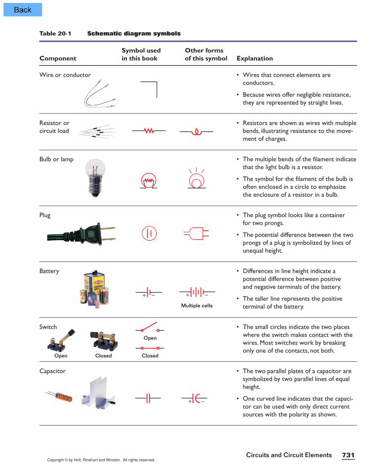
Table 20-1 Schematic diagram symbols
Symbol used Other forms Component in this book of this symbol Explanation
Wire or conductor • Wires that connect elements areconductors.
• Because wires offer negligible resistance,they are represented by straight lines.
Resistor or • Resistors are shown as wires with multiplecircuit load bends, illustrating resistance to the move-
ment of charges.
Bulb or lamp • The multiple bends of the filament indicatethat the light bulb is a resistor.
• The symbol for the filament of the bulb isoften enclosed in a circle to emphasizethe enclosure of a resistor in a bulb.
Plug • The plug symbol looks like a containerfor two prongs.
• The potential difference between the twoprongs of a plug is symbolized by lines ofunequal height.
Battery • Differences in line height indicate apotential difference between positiveand negative terminals of the battery.
• The taller line represents the positiveterminal of the battery.
Switch • The small circles indicate the two placeswhere the switch makes contact with thewires. Most switches work by breakingonly one of the contacts, not both.
Capacitor • The two parallel plates of a capacitor aresymbolized by two parallel lines of equalheight.
• One curved line indicates that the capaci-tor can be used with only direct currentsources with the polarity as shown.
+ − + −
+ −
Open
ClosedOpen Closed
Multiple cells
ELECTRIC CIRCUITS
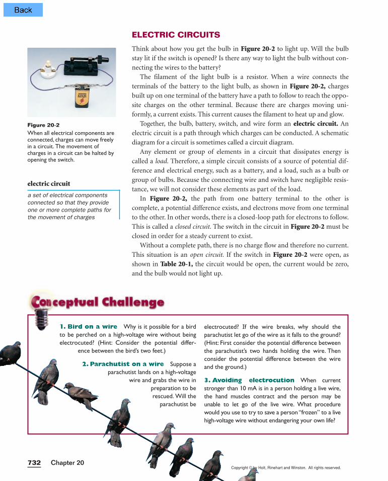
Think about how you get the bulb in Figure 20-2 to light up. Will the bulb
stay lit if the switch is opened? Is there any way to light the bulb without con-
necting the wires to the battery?
The filament of the light bulb is a resistor. When a wire connects the
terminals of the battery to the light bulb, as shown in Figure 20-2, charges
built up on one terminal of the battery have a path to follow to reach the oppo-
site charges on the other terminal. Because there are charges moving uni-
formly, a current exists. This current causes the filament to heat up and glow.
Together, the bulb, battery, switch, and wire form an electric circuit. An
electric circuit is a path through which charges can be conducted. A schematic
diagram for a circuit is sometimes called a circuit diagram.
Any element or group of elements in a circuit that dissipates energy is
called a load. Therefore, a simple circuit consists of a source of potential dif-
ference and electrical energy, such as a battery, and a load, such as a bulb or
group of bulbs. Because the connecting wire and switch have negligible resis-
tance, we will not consider these elements as part of the load.
In Figure 20-2, the path from one battery terminal to the other is
complete, a potential difference exists, and electrons move from one terminal
to the other. In other words, there is a closed-loop path for electrons to follow.
This is called a closed circuit. The switch in the circuit in Figure 20-2 must be
closed in order for a steady current to exist.
Without a complete path, there is no charge flow and therefore no current.
This situation is an open circuit. If the switch in Figure 20-2 were open, as
shown in Table 20-1, the circuit would be open, the current would be zero,
and the bulb would not light up.
Figure 20-2When all electrical components areconnected, charges can move freelyin a circuit. The movement ofcharges in a circuit can be halted byopening the switch.
electric circuit
a set of electrical componentsconnected so that they provideone or more complete paths forthe movement of charges
732
electrocuted? If the wire breaks, why should theparachutist let go of the wire as it falls to the ground?(Hint: First consider the potential difference betweenthe parachutist’s two hands holding the wire. Thenconsider the potential difference between the wireand the ground.)
3. Avoiding electrocution When currentstronger than 10 mA is in a person holding a live wire,the hand muscles contract and the person may beunable to let go of the live wire. What procedurewould you use to try to save a person “frozen” to a livehigh-voltage wire without endangering your own life?
1. Bird on a wire Why is it possible for a birdto be perched on a high-voltage wire without beingelectrocuted? (Hint: Consider the potential differ-
ence between the bird’s two feet.)
2. Parachutist on a wire Suppose aparachutist lands on a high-voltage
wire and grabs the wire inpreparation to berescued. Will the
parachutist be
Chapter 20Copyright © by Holt, Rinehart and Winston. All rights reserved.

Copyright © by Holt, Rinehart and Winston. All rights reserved.
Many electrical products, such asdecorative lights, have a prominenttag labeled “UL.” This mark, fromUnderwriters Laboratories,indicates that the product has beentested by UL engineers for electrical, fire, and other hazards.
733Circuits and Circuit Elements
Light bulbs contain a complete conducting path
How does a light bulb contain a complete conducting path? When you look at
a clear light bulb, you can see the twisted filament inside that provides a por-
tion of the conducting path for the circuit. However, the bulb screws into a
single socket; it seems to have only a single contact, the rounded part at the
bulb’s base.
Closer examination of the socket reveals that it has two contacts inside.
One contact, in the bottom of the socket, is connected to the wire going to one
side of the filament. The other contact is in the side of the socket, and it is
connected to the wire going to the other side of the filament.
The placement of the contacts within the socket indicates
how the bulb completes the circuit, as shown in Figure 20-3.Within the bulb, one side of the filament is connected with wires to
the contact at the light bulb’s base, (a). The other side of the fila-
ment is connected to the side of the metal base, (c). Insulating
material between the side of the base and the contact on the bot-
tom prevents the wires from being connected to each other with a
conducting material. In this way, charges have only one path to fol-
low when passing through a light bulb—through the filament, (b).When a light bulb is screwed in, the contact on one side of the
socket touches the threads on the side of the bulb’s base. The
contact on the bottom of the socket touches the contact on the
bottom of the bulb’s base. Charges then enter through the bulb’s
base, move through the bulb to the filament, and exit the bulb
through the threads. For most light bulbs, the bulb will glow
regardless of which direction the charges move. Thus, the positive
terminal of a battery can be connected to either the base of the
bulb or the threads of the bulb, as long as the negative
terminal is connected to the threads or base, respectively.
All that matters is that there is a complete conducting
path for the charges to move through the circuit.
Short circuits can be hazardous
Without a load, such as a bulb or other resistor, the circuit contains little resis-
tance to the movement of charges. This situation is called a short circuit. For
example, a short circuit occurs when a wire is connected from one terminal of
a battery to the other by a wire with little resistance. This commonly occurs
when uninsulated wires connected to different terminals come into contact
with each other.
When short circuits occur in the wiring of your home, the increase in cur-
rent can become unsafe. Most wires cannot withstand the increased current,
and they begin to overheat. The wire’s insulation may even melt or cause a fire.
(c)
(b)
(a)
Figure 20-3Light bulbs contain a complete conducting path. When a light bulb is screwed in, charges can enter through the base (a), movealong the wire to the filament (b),and exit the bulb through thethreads (c).

Copyright © by Holt, Rinehart and Winston. All rights reserved.Chapter 20734
The source of potential difference and electrical energy is the circuit’s emf
Is it possible to light a bulb using only wires and no battery? Without a potential
difference, there is no charge flow and no current. A battery is necessary because
the battery is the source of potential difference and electrical energy for the cir-
cuit. So the bulb must be connected to a battery to be lit.
Any device that increases the potential energy of charges circulating in a circuit
is a source of emf. The emf is the energy per unit charge supplied by a source of
electric current. Think of such a source as a “charge pump”that forces electrons to
move in a certain direction. Batteries and generators are examples of emf sources.
For conventional current, the terminal voltage is less than the emf
Look at the battery attached to the light bulb in the circuit shown in Figure 20-4. As shown in the inset, instead of behaving only like a source of emf, the
battery behaves as if it contains both an emf source and a resistor. The battery’s
internal resistance to current is the result of moving charges colliding with
atoms inside the battery while the charges are traveling from one terminal to the
other. Thus, when charges move con-
ventionally in a battery, the potential
difference across the battery’s termi-
nals, the terminal voltage, is actually
slightly less than the emf.
Unless otherwise stated, any refer-
ence in this book to the potential dif-
ference across a battery should be
thought of as the potential difference
measured across the battery’s terminals
rather than as the emf of the battery. In
other words, all examples and end-of-
chapter problems will disregard inter-
nal resistance.
emf
the energy per unit chargesupplied by a source of electriccurrent
Simple Circuits
M A T E R I A L S L I S T
1 miniature light bulb
1 D-cell battery
wires
rubber band or tape
SAFETY CAUTION
Do not perform this lab with any batteries or electrical devices other than those listed here.
Never work with electricity near water. Be sure the floor and all work surfaces are dry.
Connect the bulb to the battery usingtwo wires, using a rubber band or tape to
hold the wire to the battery. Once youhave gotten the bulb to light, try differentarrangements to see whether there ismore than one way to get the bulb to light.Can you make the bulb light using just onewire? Diagram each arrangement that youtry, and note whether it produces light.
Explain exactly which parts of the bulb,battery, and wire must be connected forthe light bulb to produce light.
+ −
Small internalresistance
(b)
(c)
(a)
Figure 20-4(a) A battery in a circuit behaves as if it con-tains both (b) an emf source and (c) an inter-nal resistance. For simplicity’s sake, in problemsolving it will be assumed that this internalresistance is insignificant.
TOPIC: Electric circuitsGO TO: www.scilinks.orgsciLINKS CODE: HF2201
NSTA

Copyright © by Holt, Rinehart and Winston. All rights reserved.735Circuits and Circuit Elements
Potential difference across a load equals the terminal voltage
When a charge moves within a battery from one terminal to the other, the
chemical energy of the battery is converted to the electrical potential energy of
the charge. Then, as the charge leaves the battery terminal and moves through
the circuit, its electrical potential energy is converted to other forms of energy.
For instance, when the load is a resistor, the electrical potential energy of the
charge is converted to the internal energy of the resistor and dissipated as
thermal energy and light energy.
Because of conservation of energy, the charge must gain as much energy as
it loses in one complete trip around the circuit (starting and ending at the same
place). Thus, the electrical potential energy gained in the battery must equal
the energy dissipated by the load. Because the potential difference is the mea-
surement of potential energy per amount of charge, the potential increase
across the battery must equal the potential decrease across the load.
Section Review
1. Identify the types of elements in the schematic diagram
illustrated in Figure 20-5 and the number of each type.
2. Using the symbols listed in Table 20-1, draw a schematic
diagram that contains two resistors, an emf source, and a
closed switch.
3. In which of the schematic diagrams shown below will there be no current?
4. If the potential difference across the bulb in a certain flashlight is 3.0 V,
what is the potential difference across the combination of batteries used
to power it?
5. Physics in Action In what form is the electrical energy that is
supplied to a string of decorative lights dissipated?
Figure 20-5
Figure 20-6 Figure 20-7
Figure 20-8 Figure 20-9
Copyright © by Holt, Rinehart and Winston. All rights reserved.Chapter 20736
RESISTORS IN SERIES
In a circuit that consists of a single bulb and a battery, the potential difference
across the bulb equals the terminal voltage. The total current in the circuit can
be found using the equation ∆V = IR.
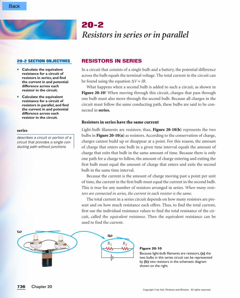
What happens when a second bulb is added to such a circuit, as shown in
Figure 20-10? When moving through this circuit, charges that pass through
one bulb must also move through the second bulb. Because all charges in the
circuit must follow the same conducting path, these bulbs are said to be con-
nected in series.
Resistors in series have the same current
Light-bulb filaments are resistors; thus, Figure 20-10(b) represents the two
bulbs in Figure 20-10(a) as resistors. According to the conservation of charge,
charges cannot build up or disappear at a point. For this reason, the amount
of charge that enters one bulb in a given time interval equals the amount of
charge that exits that bulb in the same amount of time. Because there is only
one path for a charge to follow, the amount of charge entering and exiting the
first bulb must equal the amount of charge that enters and exits the second
bulb in the same time interval.
Because the current is the amount of charge moving past a point per unit
of time, the current in the first bulb must equal the current in the second bulb.
This is true for any number of resistors arranged in series. When many resis-
tors are connected in series, the current in each resistor is the same.
The total current in a series circuit depends on how many resistors are pre-
sent and on how much resistance each offers. Thus, to find the total current,
first use the individual resistance values to find the total resistance of the cir-
cuit, called the equivalent resistance. Then the equivalent resistance can be
used to find the current.
20-2Resistors in series or in parallel
20-2 SECTION OBJECTIVES
• Calculate the equivalentresistance for a circuit ofresistors in series, and findthe current in and potentialdifference across eachresistor in the circuit.
• Calculate the equivalentresistance for a circuit ofresistors in parallel, and findthe current in and potentialdifference across eachresistor in the circuit.
series
describes a circuit or portion of acircuit that provides a single con-ducting path without junctions
h
(a)
R1 R2
(b)
Figure 20-10Because light-bulb filaments are resistors, (a) thetwo bulbs in this series circuit can be representedby (b) two resistors in the schematic diagramshown on the right.

Copyright © by Holt, Rinehart and Winston. All rights reserved.737Circuits and Circuit Elements
The equivalent resistance in a series circuit is the sum of the circuit’s resistances
As described in Section 20-1, the potential difference across the battery, ∆V,
must equal the potential difference across the load, ∆V1 + ∆V2, where ∆V1 is
the potential difference across R1 and ∆V2 is the potential difference across R2.
∆V = ∆V1 + ∆V2
According to ∆V = IR, the potential difference across each resistor is equal
to the current in that resistor multiplied by the resistance.
∆V = I1R1 + I2R2
Because the resistors are in series, the current in each is the same. For this
reason, I1 and I2 can be replaced with a single variable for the current, I.
∆V = I(R1 + R2)
Finding a value for the equivalent resistance of the circuit is now possible.
If you imagine the equivalent resistance replacing the original two resistors, as
shown in Figure 20-11, you can treat the circuit as if it contains only one
resistor and use ∆V = IR to relate the total potential difference, current, and
equivalent resistance.∆V = I(Req)
Now set the last two equations for ∆V equal to each other, and divide by the
current.∆V = I(Req) = I(R1 + R2)
Req = R1 + R2
Thus, the equivalent resistance of the series combination is the sum of the
individual resistances. An extension of this analysis shows that the equivalent
resistance of two or more resistors connected in series can be calculated using
the following equation.
Because Req represents the sum of the individual resistances that have been
connected in series, the equivalent resistance of a series combination of resistors
is always greater than any individual resistance.
To find the total current in a series circuit, first simplify the circuit to a sin-
gle equivalent resistance using the boxed equation above, then use ∆V = IR to
calculate the current.
I = R
∆
e
V
q
RESISTORS IN SERIES
Req = R1 + R2 + R3 . . .
Equivalent resistance equals the total of individual resistances in series.
Figure 20-11(a) The two resistors in the actualcircuit have the same effect on thecurrent in the circuit as (b) theequivalent resistor.
I
I
I
+ −
R1
Req
R2
(a)
(b)
Copyright © by Holt, Rinehart and Winston. All rights reserved.Chapter 20738
Because the current in each bulb is equal to the total current, you can also
use ∆V = IR to calculate the potential difference across each resistor.
∆V1 = IR1 and ∆V2 = IR2
The method described above can be used to find the potential difference
across resistors in a series circuit containing any number of resistors.
SAMPLE PROBLEM 20A
Resistors in series
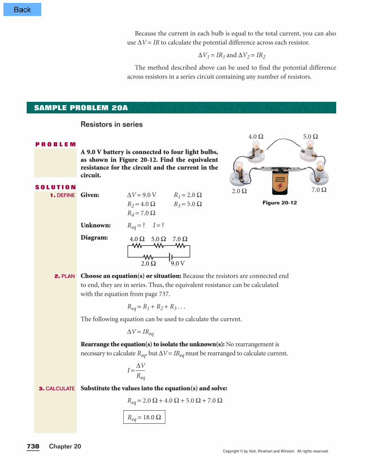
P R O B L E MA 9.0 V battery is connected to four light bulbs,as shown in Figure 20-12. Find the equivalentresistance for the circuit and the current in thecircuit.
S O L U T I O NGiven: ∆V = 9.0 V R1 = 2.0 Ω
R2 = 4.0 Ω R3 = 5.0 ΩR4 = 7.0 Ω
Unknown: Req = ? I = ?
Diagram:
Choose an equation(s) or situation: Because the resistors are connected end
to end, they are in series. Thus, the equivalent resistance can be calculated
with the equation from page 737.
Req = R1 + R2 + R3 . . .
The following equation can be used to calculate the current.
∆V = IReq
Rearrange the equation(s) to isolate the unknown(s): No rearrangement is
necessary to calculate Req, but ∆V = IReq must be rearranged to calculate current.
I = R
∆
e
V
q
Substitute the values into the equation(s) and solve:
Req = 2.0 Ω + 4.0 Ω + 5.0 Ω + 7.0 Ω
Req = 18.0 Ω
9.0 V2.0 Ω
4.0 Ω 7.0 Ω5.0 Ω
1. DEFINE
2. PLAN
3. CALCULATE
Figure 20-12
4.0 Ω
2.0 Ω
5.0 Ω
7.0 Ω
Copyright © by Holt, Rinehart and Winston. All rights reserved.739Circuits and Circuit Elements
Substitute the equivalent resistance value into the equation for current.
I = R
∆
e
V
q =
1
9
8
.
.
0
0
V
Ω
For resistors connected in series, the equivalent resistance should be greater
than the largest resistance in the circuit.
18.0 Ω > 7.0 Ω
I = 0.50 A
4. EVALUATE
PRACTICE 20A
1. A 12.0 V storage battery is connected to three resistors, 6.75 Ω, 15.3 Ω,
and 21.6 Ω, respectively. The resistors are joined in series.
a. Calculate the equivalent resistance.
b. What is the current in the circuit?
2. A 4.0 Ω resistor, an 8.0 Ω resistor, and a 12.0 Ω resistor are
connected in series with a 24.0 V battery.
a. Calculate the equivalent resistance.
b. Calculate the current in the circuit.
c. What is the current in each resistor?
3. Because the current in the equivalent resistor of Sample Problem 20A
is 0.50 A, it must also be the current in each resistor of the original
circuit. Find the potential difference across each resistor.
4. A series combination of two resistors, 7.25 Ω and 4.03 Ω, is connected
to a 9.00 V battery.
a. Calculate the equivalent resistance of the circuit and the current.
b. What is the potential difference across each resistor?
5. A 7.0 Ω resistor is connected in series with another resistor and a 4.5 V
battery. The current in the circuit is 0.60 A. Calculate the value of the
unknown resistance.
6. Several light bulbs are connected in series across a 115 V source
of emf.
a. What is the equivalent resistance if the current in the circuit is 1.70 A?
b. If each light bulb has a resistance of 1.50 Ω, how many light bulbs are
in the circuit?
Resistors in series

Copyright © by Holt, Rinehart and Winston. All rights reserved.Chapter 20740
Series circuits require all elements to conduct
What happens to a series circuit when a single bulb burns out? Consider what
a circuit diagram for a string of lights with one broken filament would look
like. As the schematic diagram in Figure 20-13 shows, the broken filament
means that there is a gap in the conducting pathway used to make up the cir-
cuit. Because the circuit is no longer closed, there is no current in it and all of
the bulbs go dark.
Why, then, would anyone arrange resistors in series? Resistors can be placed
in series with a device in order to regulate the current in that device. In the case
of decorative lights, adding an additional bulb will decrease the current in each
bulb. Thus, the filament of each bulb need not withstand such a high current.
Another advantage to placing resistors in series is that several lesser resistances
can be used to add up to a single greater resistance that is unavailable. Finally,
in some cases, it is important to have a circuit that will have no current if any
one of its component parts fails. This technique is used in a variety of contexts,
including some burglar alarm systems.
RESISTORS IN PARALLEL
As discussed above, when a single bulb in a series light set burns out, the entire
string of lights goes dark because the circuit is no longer closed. What would
happen if there were alternative pathways for the movement of charge, as
shown in Figure 20-14?
A wiring arrangement that provides alternative pathways for the move-
ment of a charge is a parallel arrangement. The bulbs of the decorative light
set shown in the schematic diagram in Figure 20-14 are arranged in parallel
with each other.
Resistors in parallel have the same potential differences across them
To explore the consequences of arranging resistors in parallel, consider the two
bulbs connected to a battery in Figure 20-15(a). In this arrangement, the left
Figure 20-14These decorative lights are wired in parallel. Notice that in a par-allel arrangement there is more than one path for current.
parallel
describes two or morecomponents in a circuit that areconnected across commonpoints or junctions, providingseparate conducting paths forthe current
Figure 20-13A burnt-out filament in a bulb hasthe same effect as an open switch.Because this series circuit is nolonger complete, there is no cur-rent in the circuit.
TOPIC: ResistorsGO TO: www.scilinks.orgsciLINKS CODE: HF2202
NSTA
Copyright © by Holt, Rinehart and Winston. All rights reserved.
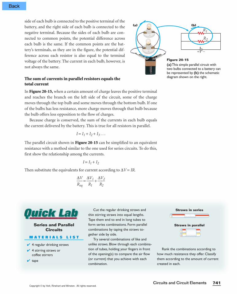
side of each bulb is connected to the positive terminal of the
battery, and the right side of each bulb is connected to the
negative terminal. Because the sides of each bulb are con-
nected to common points, the potential difference across
each bulb is the same. If the common points are the bat-
tery’s terminals, as they are in the figure, the potential dif-
ference across each resistor is also equal to the terminal
voltage of the battery. The current in each bulb, however, is
not always the same.
The sum of currents in parallel resistors equals thetotal current
In Figure 20-15, when a certain amount of charge leaves the positive terminal
and reaches the branch on the left side of the circuit, some of the charge
moves through the top bulb and some moves through the bottom bulb. If one
of the bulbs has less resistance, more charge moves through that bulb because
the bulb offers less opposition to the flow of charges.
Because charge is conserved, the sum of the currents in each bulb equals
the current delivered by the battery. This is true for all resistors in parallel.
I = I1 + I2 + I3 . . .
The parallel circuit shown in Figure 20-15 can be simplified to an equivalent
resistance with a method similar to the one used for series circuits. To do this,
first show the relationship among the currents.
I = I1 + I2
Then substitute the equivalents for current according to ∆V = IR.
R
∆
e
V
q =
∆R
V
1
1 + ∆R
V
2
2
Series and Parallel Circuits
M A T E R I A L S L I S T
4 regular drinking straws
4 stirring straws or coffee stirrers
tape
Cut the regular drinking straws andthin stirring straws into equal lengths.Tape them end to end in long tubes toform series combinations. Form parallelcombinations by taping the straws to-gether side by side.
Try several combinations of like andunlike straws. Blow through each combina-tion of tubes, holding your fingers in frontof the opening(s) to compare the air flow(or current) that you achieve with eachcombination.
Rank the combinations according tohow much resistance they offer. Classifythem according to the amount of currentcreated in each.
Straws in series
Straws in parallel
741Circuits and Circuit Elements
R1
R2
+ −
(b)(a)
Figure 20-15(a)This simple parallel circuit withtwo bulbs connected to a battery canbe represented by (b) the schematicdiagram shown on the right.
Copyright © by Holt, Rinehart and Winston. All rights reserved.Chapter 20742
Because the potential difference across each bulb in a parallel arrangement
equals the terminal voltage (∆V = ∆V1 = ∆V2), you can divide each side of the
equation by ∆V to get the following equation.
R
1
eq =
R
1
1 +
R
1
2
An extension of this analysis shows that the equivalent resistance of two or
more resistors connected in parallel can be calculated using the following
equation.
Notice that this equation does not give the value of the equivalent
resistance directly. You must take the reciprocal of your answer to obtain the
value of the equivalent resistance.
Because of the reciprocal relationship, the equivalent resistance for a parallel
arrangement of resistors must always be less than the smallest resistance in the
group of resistors.
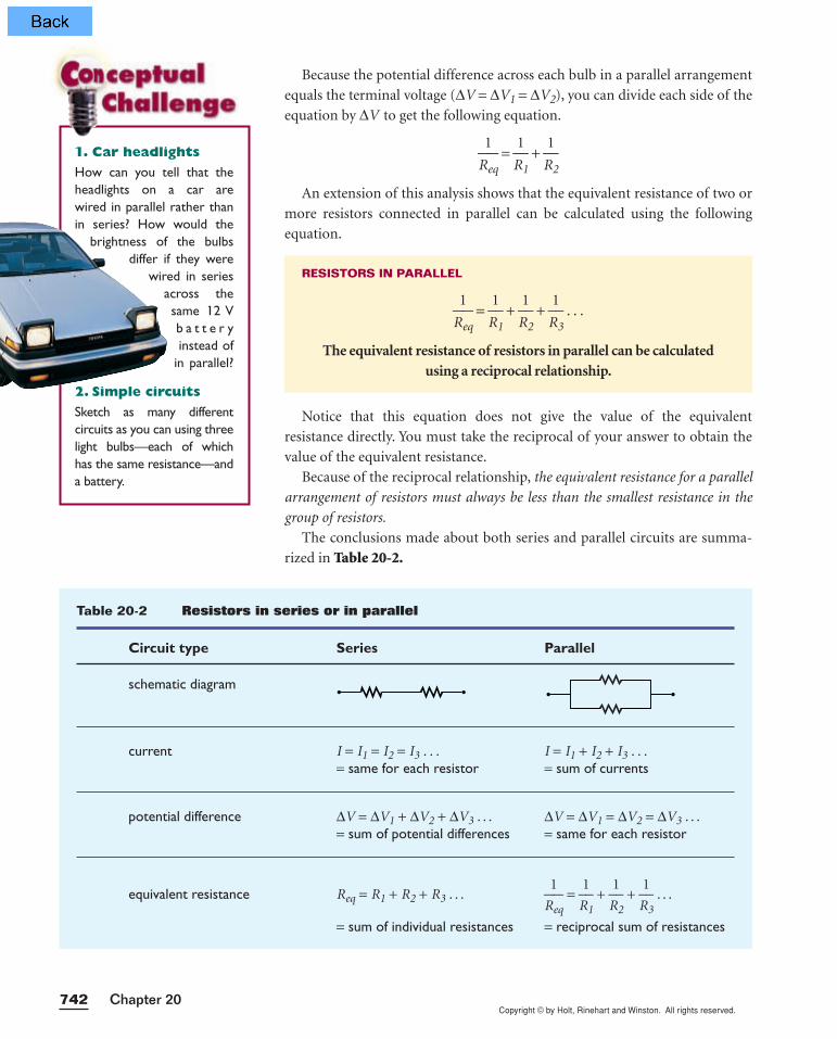
The conclusions made about both series and parallel circuits are summa-
rized in Table 20-2.
RESISTORS IN PARALLEL
R
1
eq =
R
1
1 +
R
1
2 +
R
1
3 . . .
The equivalent resistance of resistors in parallel can be calculated using a reciprocal relationship.
1. Car headlights
How can you tell that theheadlights on a car are wired in parallel rather thanin series? How would the
brightness of the bulbsdiffer if they were
wired in seriesacross thesame 12 Vb a t t e r yinstead of
in parallel?
2. Simple circuits
Sketch as many different circuits as you can using threelight bulbs—each of whichhas the same resistance—anda battery.
Table 20-2 Resistors in series or in parallel
Circuit type Series Parallel
schematic diagram
current I = I1 = I2 = I3 . . . I = I1 + I2 + I3 . . .= same for each resistor = sum of currents
potential difference ∆V = ∆V1 + ∆V2 + ∆V3 . . . ∆V = ∆V1 = ∆V2 = ∆V3 . . .= sum of potential differences = same for each resistor
equivalent resistance Req = R1 + R2 + R3 . . . R
1
eq =
R
1
1 +
R
1
2 +
R
1
3 . . .
= sum of individual resistances = reciprocal sum of resistances

Copyright © by Holt, Rinehart and Winston. All rights reserved.743Circuits and Circuit Elements
SAMPLE PROBLEM 20B
Resistors in parallel
P R O B L E MA 9.0 V battery is connected to four resistors, asshown in Figure 20-16. Find the equivalent resis-tance for the circuit and the total current in thecircuit.
S O L U T I O NGiven: ∆V = 9.0 V R1 = 2.0 Ω
R2 = 4.0 Ω R3 = 5.0 ΩR4 = 7.0 Ω
Unknown: Req = ? I = ?
Diagram:
Choose an equation(s) or situation: Because both sides of each resistor are
connected to common points, they are in parallel. Thus, the equivalent resis-
tance can be calculated with the equation from p. 742.
R
1
eq =
R
1
1 +
R
1
2 +
R
1
3 . . . for parallel
The following equation can be used to calculate the current.
∆V = IReq
Rearrange the equation(s) to isolate the unknown(s): No rearrangement
is necessary to calculate Req; rearrange ∆V = IReq to calculate current.
I = R
∆
e
V
q
Substitute the values into the equation(s) and solve: Remember to take the
reciprocal in the final step.
R
1
eq =
2.0
1
Ω +
4.0
1
Ω +
5.0
1
Ω +
7.0
1
Ω
R
1
eq =
0
1
.5
Ω0
+ 0
1
.2
Ω5
+ 0
1
.2
Ω0
+ 0
1
.1
Ω4
= 1
1
.0
Ω9
Req = 1
1
.0
Ω9
Req = 0.917 Ω
2.0 Ω
5.0 Ω
9.0 V
4.0 Ω
7.0 Ω
1. DEFINE
2. PLAN
3. CALCULATE
continued onnext page
Figure 20-16
7.0 Ω5.0 Ω
4.0 Ω2.0 Ω
Copyright © by Holt, Rinehart and Winston. All rights reserved.Chapter 20744
Parallel circuits do not require all elements to conduct
What happens when a bulb burns out in a string of decorative lights that is
wired in parallel? There is no current in that branch of the circuit, but each of
the parallel branches provides a separate alternative pathway for current.
Thus, the potential difference supplied to the other branches and the current
in these branches remain the same, and the bulbs in these branches remain lit.
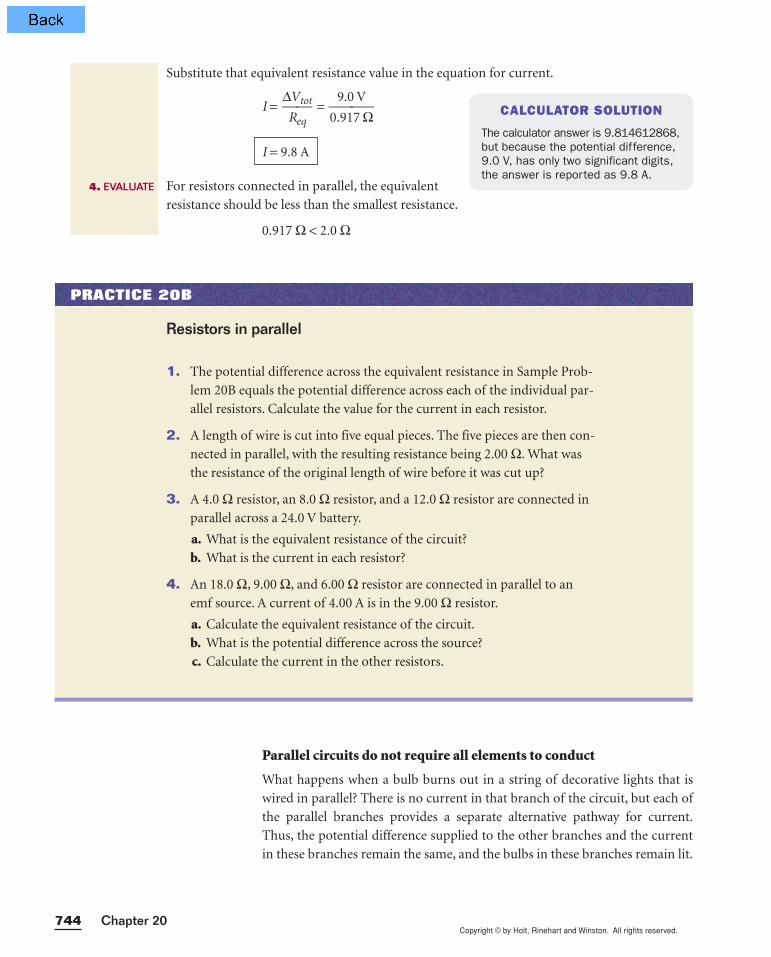
Substitute that equivalent resistance value in the equation for current.
I = ∆R
V
e
t
q
ot = 0.
9
9
.
1
0
7
V
Ω
For resistors connected in parallel, the equivalent
resistance should be less than the smallest resistance.
0.917 Ω < 2.0 Ω
I = 9.8 A
4. EVALUATE
CALCULATOR SOLUTION
The calculator answer is 9.814612868,but because the potential difference,9.0 V, has only two significant digits,the answer is reported as 9.8 A.
1. The potential difference across the equivalent resistance in Sample Prob-
lem 20B equals the potential difference across each of the individual par-
allel resistors. Calculate the value for the current in each resistor.
2. A length of wire is cut into five equal pieces. The five pieces are then con-
nected in parallel, with the resulting resistance being 2.00 Ω. What was
the resistance of the original length of wire before it was cut up?
3. A 4.0 Ω resistor, an 8.0 Ω resistor, and a 12.0 Ω resistor are connected in
parallel across a 24.0 V battery.
a. What is the equivalent resistance of the circuit?
b. What is the current in each resistor?
4. An 18.0 Ω, 9.00 Ω, and 6.00 Ω resistor are connected in parallel to an
emf source. A current of 4.00 A is in the 9.00 Ω resistor.
a. Calculate the equivalent resistance of the circuit.
b. What is the potential difference across the source?
c. Calculate the current in the other resistors.
Resistors in parallel
PRACTICE 20B
Copyright © by Holt, Rinehart and Winston. All rights reserved.745Circuits and Circuit Elements
When resistors are wired in parallel with an emf source, the potential differ-
ence across each resistor always equals the potential difference across the
source. Because household circuits are arranged in parallel, appliance manu-
facturers are able to standardize their design, producing devices that all operate
at the same potential difference. (Because the potential difference provided by
a wall outlet in a home in North America is not the same as the potential differ-
ence that is standard on other continents, appliances made in North America
are not always compatible with wall outlets in homes on other continents.)
Because household devices operate at the same potential difference, manu-
facturers can choose the resistance of the device to ensure that the current in
the device will be neither too high nor too low for the internal wiring and
other components that make up the device.
Additionally, the equivalent resistance of several parallel resistors is less
than the resistance of any of the individual resistors. Thus, a low equivalent
resistance can be created with a group of resistors of higher resistances.
Section Review
1. Two resistors are wired in series. In another circuit, the same two resistors
are wired in parallel. In which circuit is the equivalent resistance greater?
2. A 5 Ω, a 10 Ω, and a 15 Ω resistor are connected in series.
a. Which resistor has the most current in it?
b. Which resistor has the largest potential difference across it?
3. A 5 Ω, a 10 Ω, and a 15 Ω resistor are connected in parallel.
a. Which resistor has the most current in it?
b. Which resistor has the largest potential difference across it?
4. Find the current in and potential difference across each of the resistors in
the following circuits:
a. a 2.0 Ω and a 4.0 Ω resistor wired in series with a 12 V source
b. a 2.0 Ω and a 4.0 Ω resistor wired in parallel with a 12 V source
c. a 4.0 Ω and a 12.0 Ω resistor wired in series with a 4.0 V source
d. a 4.0 Ω and a 12.0 Ω resistor wired in parallel with a 4.0 V source
5. Find the current in and potential difference across each of the resistors in
the following circuits:
a. a 150 Ω and a 180 Ω resistor wired in series with a 12 V source
b. a 150 Ω and a 180 Ω resistor wired in parallel with a 12 V source
6. Physics in Action A string of 35 miniature decorative lights is
wired in series. If it draws 0.20 A of current when it is connected to a
120.0 V emf source, what is the resistance of each miniature bulb?
Copyright © by Holt, Rinehart and Winston. All rights reserved.Chapter 20746
20-3Complex resistor combinations
20-3 SECTION OBJECTIVES
• Calculate the equivalentresistance for a complexcircuit involving both seriesand parallel portions.
• Calculate the current in andpotential difference acrossindividual elements within acomplex circuit.
RESISTORS COMBINED BOTH IN PARALLEL AND IN SERIES
Series and parallel circuits are not often encountered independent of one
another. Most circuits today employ both series and parallel wiring to utilize
the advantages of each type.
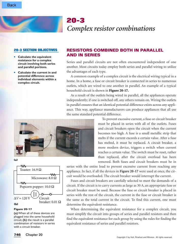
A common example of a complex circuit is the electrical wiring typical in a
home. In a home, a fuse or circuit breaker is connected in series to numerous
outlets, which are wired to one another in parallel. An example of a typical
household circuit is shown in Figure 20-17.As a result of the outlets being wired in parallel, all the appliances operate
independently; if one is switched off, any others remain on. Wiring the outlets
in parallel ensures that an identical potential difference exists across any appli-
ance. This way, appliance manufacturers can produce appliances that all use
the same standard potential difference.
To prevent excessive current, a fuse or circuit breaker
must be placed in series with all of the outlets. Fuses
and circuit breakers open the circuit when the current
becomes too high. A fuse is a small metallic strip that
melts if the current exceeds a certain value. After a fuse
has melted, it must be replaced. A circuit breaker, a
more modern device, triggers a switch when current
reaches a certain value. The switch must be reset, rather
than replaced, after the circuit overload has been
removed. Both fuses and circuit breakers must be in
series with the entire load to prevent excessive current from reaching any
appliance. In fact, if all the devices in Figure 20-17 were used at once, the cir-
cuit would be overloaded. The circuit breaker would interrupt the current.
Fuses and circuit breakers are carefully selected to meet the demands of a
circuit. If the circuit is to carry currents as large as 30 A, an appropriate fuse or
circuit breaker must be used. Because the fuse or circuit breaker is placed in
series with the rest of the circuit, the current in the fuse or circuit breaker is
the same as the total current in the circuit. To find this current, one must
determine the equivalent resistance.
When determining the equivalent resistance for a complex circuit, you
must simplify the circuit into groups of series and parallel resistors and then
find the equivalent resistance for each group by using the rules for finding the
equivalent resistance of series and parallel resistors.
Toaster: 16.9 Ω
Popcorn popper: 10.0 Ω
Circuit breaker: 0.01 Ω
∆V = 120 V
Microwave: 8.0 Ω
(b)
Figure 20-17(a) When all of these devices areplugged into the same householdcircuit, (b) the result is a parallelcombination of resistors in serieswith a circuit breaker.
(a)

Copyright © by Holt, Rinehart and Winston. All rights reserved.747Circuits and Circuit Elements
SAMPLE PROBLEM 20C
Equivalent resistance
P R O B L E MDetermine the equivalent resistance of the complex circuit shown in Figure 20-18.
S O L U T I O NRedraw the circuit as a group of resistors along one side of the circuit.
Because bends in a wire do not affect the cir-
cuit, they do not need to be represented in a
schematic diagram. Redraw the circuit with-
out the corners, keeping the arrangement of
the circuit elements the same, as shown in
Figure 20-19. For now, disregard the emf
source and work only with the resistances.
Identify components in series, and calculate their equivalent resistance.Resistors in groups (a) and (b) in Figure 20-20 are in series.
For group (a): Req = 3.0 Ω + 6.0 Ω = 9.0 ΩFor group (b): Req = 6.0 Ω + 2.0 Ω = 8.0 Ω
Identify components in parallel, and calcu-late their equivalent resistance.
Resistors in group (c) in Figure 20-20 are in parallel.
For group (c):
R
1
eq =
8.0
1
Ω +
4.0
1
Ω =
0
1
.1
Ω2
+ 0
1
.2
Ω5
= 0
1
.3
Ω7
Req = 2.7 Ω
Repeat steps 2 and 3 until the resistors in the circuit arereduced to a single equivalent resistance.
The remainder of the resistors, group (d) in Figure 20-20,are in series.
For group (d): Req = 9.0 Ω + 2.7 Ω + 1.0 Ω
Redraw the circuit as in Figure 20-20, with the equivalent resistance connected to the original emf source.
Req = 12.7 Ω
1.
2.
3.
4.
5.
REASONINGThe best approach is to divide the circuit into groups of
series and parallel resistors. This way the methods
presented in Sample Problems 20B and 20C can be
used to calculate the equivalent resistance for each group.
6.0 Ω
4.0 Ω
2.0 Ω3.0 Ω 6.0 Ω 1.0 Ω
4.0 Ω
1.0 Ω2.7 Ω9.0 Ω
8.0 Ω1.0 Ω9.0 Ω
12.7 Ω
9.0 V
(c)
(d)
(b)(a)
6.0 Ω
6.0 Ω 1.0 Ω4.0 Ω
3.0 Ω 9.0 V
2.0 Ω
Figure 20-18
Figure 20-20
4.0 Ω
1.0 Ω6.0 Ω 2.0 Ω
3.0 Ω 6.0 Ω
Figure 20-19

Copyright © by Holt, Rinehart and Winston. All rights reserved.
Work backward to find the current in and potential difference acrossa part of a circuit
Now that the equivalent resistance for a complex circuit has been determined,
you can work backward to find the current in and potential difference across
any resistor in that circuit. In the household example, substitute potential dif-
ference and equivalent resistance in ∆V = IR to find the total current in the
circuit. Because the fuse or circuit breaker is in series with the load, the cur-
rent in it is equal to the total current. Once this total current is determined,
∆V = IR can again be used to find the potential difference across the fuse or
circuit breaker.
There is no single formula for finding the current in and potential differ-
ence across a resistor buried inside a complex circuit. Instead, ∆V = IR and the
rules reviewed in Table 20-3 must be applied to smaller pieces of the circuit
until the desired values are found.
1. For each of the following sets of values, determine the equivalent
resistance for the circuit shown in Figure 20-21.
a. Ra = 25.0 Ω Rb = 3.0 Ω Rc = 40.0 Ωb. Ra = 12.0 Ω Rb = 35.0 Ω Rc = 25.0 Ωc. Ra = 15.0 Ω Rb = 28.0 Ω Rc = 12.0 Ω
2. For each of the following sets of values, determine the equivalent
resistance for the circuit shown in Figure 20-22.
a. Ra = 25.0 Ω Rb = 3.0 Ω Rc = 40.0 ΩRd = 15.0 Ω Re = 18.0 Ω
b. Ra = 12.0 Ω Rb = 35.0 Ω Rc = 25.0 ΩRd = 50.0 Ω Re = 45.0 Ω
Equivalent resistance
PRACTICE 20C
40.0 V
Ra
Rb Rc
Figure 20-21
25.0 V
Ra
Rb
ReRd
Rc
Figure 20-22
Table 20-3 Series and parallel resistors
Series Parallel
current same as total add to find total
potential difference add to find total same as total
748 Chapter 20
INTERACTIV
E•
T U T O RPHYSICSPHYSICS
Module 20“Electric Circuits”provides an interactive lessonwith guided problem-solvingpractice to teach you aboutmany kinds of electric circuits,including complex combinationsof resistors.
Copyright © by Holt, Rinehart and Winston. All rights reserved.749Circuits and Circuit Elements
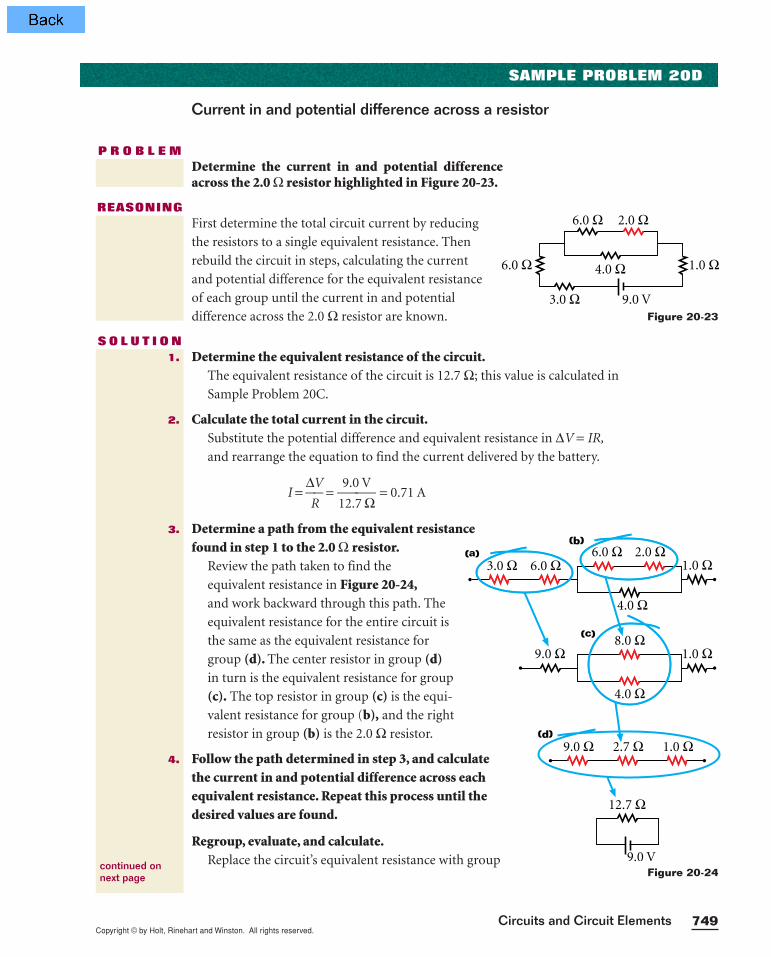
SAMPLE PROBLEM 20D
Current in and potential difference across a resistor
P R O B L E MDetermine the current in and potential differenceacross the 2.0 Ω resistor highlighted in Figure 20-23.
REASONINGFirst determine the total circuit current by reducing
the resistors to a single equivalent resistance. Then
rebuild the circuit in steps, calculating the current
and potential difference for the equivalent resistance
of each group until the current in and potential
difference across the 2.0 Ω resistor are known.
S O L U T I O NDetermine the equivalent resistance of the circuit.
The equivalent resistance of the circuit is 12.7 Ω; this value is calculated in
Sample Problem 20C.
Calculate the total current in the circuit.Substitute the potential difference and equivalent resistance in ∆V = IR,
and rearrange the equation to find the current delivered by the battery.
I = ∆R
V =
1
9
2
.
.
0
7
V
Ω = 0.71 A
Determine a path from the equivalent resistancefound in step 1 to the 2.0 Ω resistor.
Review the path taken to find the
equivalent resistance in Figure 20-24,and work backward through this path. The
equivalent resistance for the entire circuit is
the same as the equivalent resistance for
group (d). The center resistor in group (d)in turn is the equivalent resistance for group
(c). The top resistor in group (c) is the equi-
valent resistance for group (b), and the right
resistor in group (b) is the 2.0 Ω resistor.
Follow the path determined in step 3, and calculatethe current in and potential difference across eachequivalent resistance. Repeat this process until thedesired values are found.
Regroup, evaluate, and calculate.Replace the circuit’s equivalent resistance with group
1.
2.
3.
4.
continued onnext page
6.0 Ω
6.0 Ω 1.0 Ω4.0 Ω
3.0 Ω 9.0 V
2.0 Ω
Figure 20-23
6.0 Ω
4.0 Ω
2.0 Ω3.0 Ω 6.0 Ω 1.0 Ω
4.0 Ω
1.0 Ω2.7 Ω9.0 Ω
8.0 Ω1.0 Ω9.0 Ω
12.7 Ω
9.0 V
(c)
(d)
(b)(a)
Figure 20-24

Copyright © by Holt, Rinehart and Winston. All rights reserved.Chapter 20750
(d), as shown in Figure 20-25. The resistors in group
(d) are in series; therefore, the current in each resistor is
the same as the current in the equivalent resistance, which
equals 0.71 A. The potential difference across the 2.7 Ωresistor in group (d) can be calculated using ∆V = IR.
Given: I = 0.71 A R = 2.7 Ω
Unknown: ∆V = ?
∆V = IR = (0.71 A)(2.7 Ω) = 1.9 V
Regroup, evaluate, and calculate.Replace the center resistor with group (c), as shown
in Figure 20-26.
The resistors in group (c) are in parallel; therefore,
the potential difference across each resistor is the
same as the potential difference across the
2.7 Ω equivalent resistance, which equals 1.9 V.
The current in the 8.0 Ω resistor in group (c) can
be calculated using ∆V = IR.
Given: ∆V = 1.9 V R = 8.0 Ω
Unknown: I = ?
I = ∆R
V =
8
1
.
.
0
9
ΩV
= 0.24 A
Regroup, evaluate, and calculate.Replace the 8.0 Ω resistor with group (b), as shown
in Figure 20-27.
The resistors in group (b) are in series; therefore,
the current in each resistor is the same as the
current in the 8.0 Ω equivalent resistance,
which equals 0.24 A.
The potential difference across the 2.0 Ω resistor
can be calculated using ∆V = IR.
Given: I = 0.24 A R = 2.0 Ω
Unknown: ∆V = ?
∆V = IR = (0.24 A) (2.0 Ω) = 0.48 V
∆V = 0.48 V
I = 0.24 A
1.0 Ω2.7 Ω
12.7 Ω
9.0 Ω(d)
Figure 20-25
4.0 Ω
1.0 Ω2.7 Ω9.0 Ω
8.0 Ω1.0 Ω9.0 Ω
(c)
Figure 20-26
6.0 Ω
4.0 Ω
2.0 Ω9.0 Ω 1.0 Ω
4.0 Ω
8.0 Ω1.0 Ω9.0 Ω
(b)
Figure 20-27
Copyright © by Holt, Rinehart and Winston. All rights reserved.Circuits and Circuit Elements
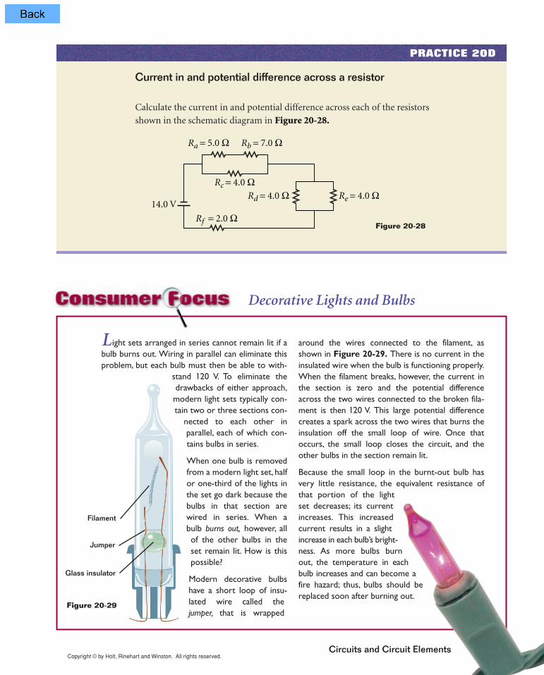
Calculate the current in and potential difference across each of the resistors
shown in the schematic diagram in Figure 20-28.
Current in and potential difference across a resistor
PRACTICE 20D
Ra = 5.0 Ω
Rc = 4.0 Ω
Rf = 2.0 Ω
Rd = 4.0 Ω14.0 V
Re = 4.0 Ω
Rb = 7.0 Ω
L ight sets arranged in series cannot remain lit if abulb burns out. Wiring in parallel can eliminate thisproblem, but each bulb must then be able to with-
stand 120 V. To eliminate thedrawbacks of either approach,modern light sets typically con-tain two or three sections con-
nected to each other inparallel, each of which con-tains bulbs in series.
When one bulb is removedfrom a modern light set, halfor one-third of the lights inthe set go dark because thebulbs in that section arewired in series. When abulb burns out, however, allof the other bulbs in theset remain lit. How is thispossible?
Modern decorative bulbshave a short loop of insu-
around the wires connected to the filament, asshown in Figure 20-29. There is no current in theinsulated wire when the bulb is functioning properly.When the filament breaks, however, the current inthe section is zero and the potential differenceacross the two wires connected to the broken fila-ment is then 120 V. This large potential differencecreates a spark across the two wires that burns theinsulation off the small loop of wire. Once thatoccurs, the small loop closes the circuit, and theother bulbs in the section remain lit.
Because the small loop in the burnt-out bulb hasvery little resistance, the equivalent resistance ofthat portion of the lightset decreases; its currentincreases. This increasedcurrent results in a slightincrease in each bulb’s bright-ness. As more bulbs burnout, the temperature in eachbulb increases and can become afire hazard; thus, bulbs should bereplaced soon after burning out.
Decorative Lights and Bulbs
Filament
Jumper
Glass insulator
Figure 20-29
Figure 20-28
lated wire called thejumper, that is wrapped
Copyright © by Holt, Rinehart and Winston. All rights reserved.Chapter 20752
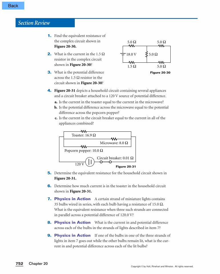
Section Review
1. Find the equivalent resistance of
the complex circuit shown in
Figure 20-30.
2. What is the current in the 1.5 Ωresistor in the complex circuit
shown in Figure 20-30?
3. What is the potential difference
across the 1.5 Ω resistor in the
circuit shown in Figure 20-30?
4. Figure 20-31 depicts a household circuit containing several appliances
and a circuit breaker attached to a 120 V source of potential difference.
a. Is the current in the toaster equal to the current in the microwave?
b. Is the potential difference across the microwave equal to the potential
difference across the popcorn popper?
c. Is the current in the circuit breaker equal to the current in all of the
appliances combined?
5. Determine the equivalent resistance for the household circuit shown in
Figure 20-31.
6. Determine how much current is in the toaster in the household circuit
shown in Figure 20-31.
7. Physics in Action A certain strand of miniature lights contains
35 bulbs wired in series, with each bulb having a resistance of 15.0 Ω.
What is the equivalent resistance when three such strands are connected
in parallel across a potential difference of 120.0 V?
8. Physics in Action What is the current in and potential difference
across each of the bulbs in the strands of lights described in item 7?
9. Physics in Action If one of the bulbs in one of the three strands of
lights in item 7 goes out while the other bulbs remain lit, what is the cur-
rent in and potential difference across each of the lit bulbs?
5.0 Ω 5.0 Ω
1.5 Ω 5.0 Ω
5.0 Ω18.0 V
Figure 20-30
Toaster: 16.9 Ω
Popcorn popper: 10.0 Ω
Circuit breaker: 0.01 Ω120 V
Microwave: 8.0 Ω
Figure 20-31
Copyright © by Holt, Rinehart and Winston. All rights reserved.753Circuits and Circuit Elements
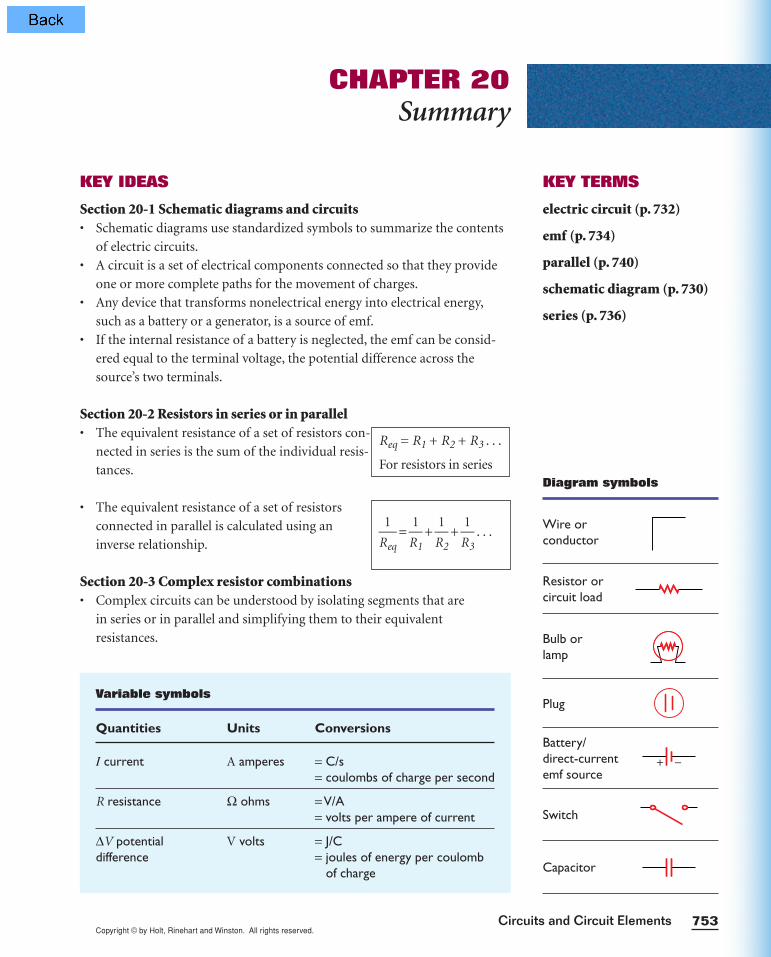
CHAPTER 20Summary
KEY TERMS
electric circuit (p. 732)
emf (p. 734)
parallel (p. 740)
schematic diagram (p. 730)
series (p. 736)
Variable symbols
Quantities Units Conversions
I current A amperes = C/s= coulombs of charge per second
R resistance Ω ohms =V/A= volts per ampere of current
∆V potential V volts = J/Cdifference = joules of energy per coulomb
of charge
KEY IDEAS
Section 20-1 Schematic diagrams and circuits• Schematic diagrams use standardized symbols to summarize the contents
of electric circuits.
• A circuit is a set of electrical components connected so that they provide
one or more complete paths for the movement of charges.
• Any device that transforms nonelectrical energy into electrical energy,
such as a battery or a generator, is a source of emf.
• If the internal resistance of a battery is neglected, the emf can be consid-
ered equal to the terminal voltage, the potential difference across the
source’s two terminals.
Section 20-2 Resistors in series or in parallel• The equivalent resistance of a set of resistors con-
nected in series is the sum of the individual resis-
tances.
• The equivalent resistance of a set of resistors
connected in parallel is calculated using an
inverse relationship.
Section 20-3 Complex resistor combinations• Complex circuits can be understood by isolating segments that are
in series or in parallel and simplifying them to their equivalent
resistances.
R
1
eq =
R
1
1 +
R
1
2 +
R
1
3 . . .
Req = R1 + R2 + R3 . . .
For resistors in seriesDiagram symbols
Wire or conductor
Resistor or circuit load
Bulb or lamp
Plug
Battery/direct-current emf source
Switch
Capacitor
+ −
Copyright © by Holt, Rinehart and Winston. All rights reserved.Chapter 20754
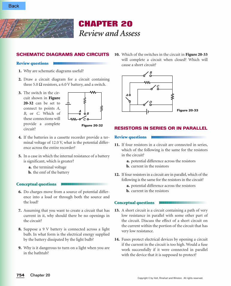
10. Which of the switches in the circuit in Figure 20-33will complete a circuit when closed? Which willcause a short circuit?
RESISTORS IN SERIES OR IN PARALLEL
Review questions
11. If four resistors in a circuit are connected in series,which of the following is the same for the resistorsin the circuit?
a. potential difference across the resistorsb. current in the resistors
12. If four resistors in a circuit are in parallel, which of thefollowing is the same for the resistors in the circuit?
a. potential difference across the resistorsb. current in the resistors
Conceptual questions
13. A short circuit is a circuit containing a path of verylow resistance in parallel with some other part ofthe circuit. Discuss the effect of a short circuit onthe current within the portion of the circuit that hasvery low resistance.
14. Fuses protect electrical devices by opening a circuitif the current in the circuit is too high. Would a fusework successfully if it were connected in parallelwith the device that it is supposed to protect?
Figure 20-33
A
B
C
D
SCHEMATIC DIAGRAMS AND CIRCUITS
Review questions
1. Why are schematic diagrams useful?
2. Draw a circuit diagram for a circuit containingthree 5.0 Ω resistors, a 6.0 V battery, and a switch.
3. The switch in the cir-cuit shown in Figure20-32 can be set toconnect to points A,B, or C. Which ofthese connections willprovide a completecircuit?
4. If the batteries in a cassette recorder provide a ter-minal voltage of 12.0 V, what is the potential differ-ence across the entire recorder?
5. In a case in which the internal resistance of a batteryis significant, which is greater?
a. the terminal voltageb. the emf of the battery
Conceptual questions
6. Do charges move from a source of potential differ-ence into a load or through both the source andthe load?
7. Assuming that you want to create a circuit that hascurrent in it, why should there be no openings inthe circuit?
8. Suppose a 9 V battery is connected across a lightbulb. In what form is the electrical energy suppliedby the battery dissipated by the light bulb?
9. Why is it dangerous to turn on a light when you arein the bathtub?
CHAPTER 20Review and Assess
A
C
B
Figure 20-32
Copyright © by Holt, Rinehart and Winston. All rights reserved.755Circuits and Circuit Elements
15. What might be an advantage of using two identicalresistors in parallel that are connected in series withanother identical parallel pair, as shown in Figure20-34, instead of using a single resistor?
Practice problems
16. A length of wire is cut into five equal pieces. If eachpiece has a resistance of 0.15 Ω, what was the resis-tance of the original length of wire?(See Sample Problem 20A.)
17. A 4.0 Ω resistor, an 8.0 Ω resistor, and a 12 Ω resis-tor are connected in series with a 24 V battery.Determine the following:
a. the equivalent resistance for the circuitb. the current in the circuit
(See Sample Problem 20A.)
18. The resistors in item 18 are connected in parallelacross a 24 V battery. Determine the following:
a. the equivalent resistance for the circuitb. the current in the circuit
(See Sample Problem 20B.)
19. An 18.0 Ω resistor, 9.00 Ω resistor, and 6.00 Ω resis-tor are connected in parallel across a 12 V battery.Determine the following:
a. the equivalent resistance for the circuitb. the current in the circuit
(See Sample Problem 20B.)
COMPLEX RESISTOR COMBINATIONS
Conceptual questions
20. A technician has two resistors, each of which has thesame resistance, R.
a. How many different resistances can the tech-nician achieve?
b. Express the effective resistance of each possi-bility in terms of R.
Figure 20-34
21. The technician in item 20 finds another resistor,so now there are three resistors with the same resistance.
a. How many different resistances can the tech-nician achieve?
b. Express the effective resistance of each possi-bility in terms of R.
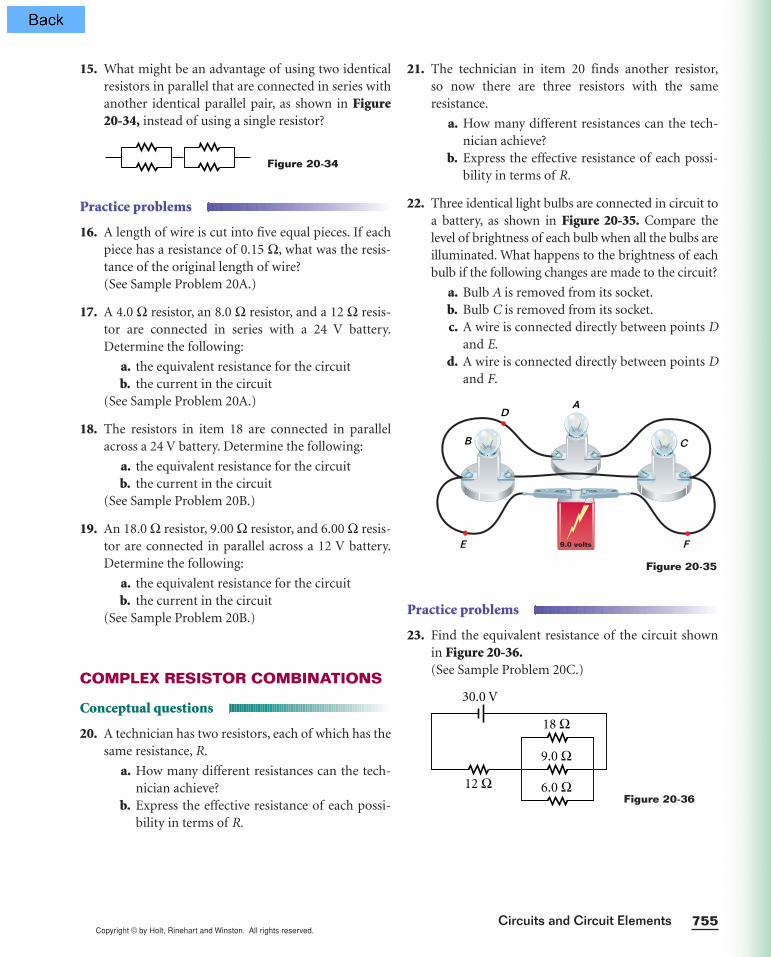
22. Three identical light bulbs are connected in circuit toa battery, as shown in Figure 20-35. Compare thelevel of brightness of each bulb when all the bulbs areilluminated. What happens to the brightness of eachbulb if the following changes are made to the circuit?
a. Bulb A is removed from its socket.b. Bulb C is removed from its socket.c. A wire is connected directly between points D
and E.d. A wire is connected directly between points D
and F.
Practice problems
23. Find the equivalent resistance of the circuit shownin Figure 20-36.(See Sample Problem 20C.)
Figure 20-3612 Ω
9.0 Ω
30.0 V
18 Ω
6.0 Ω
Figure 20-35
9.0 volts
A
B C
D
E F

Copyright © by Holt, Rinehart and Winston. All rights reserved.Chapter 20756
28. A 9.0 Ω resistor and a 6.0 Ω resistor are connectedin parallel to a battery, and the current in the 9.0 Ωresistor is found to be 0.25 A. Find the potential dif-ference across the battery.
29. A 9.0 Ω resistor and a 6.0 Ω resistor are connectedin series to a battery, and the current through the9.0 Ω resistor is 0.25 A. What is the potential differ-ence across the battery?
30. A 9.0 Ω resistor and a 6.0 Ω resistor are connectedin series with an emf source. The potential differ-ence across the 6.0 Ω resistor is measured with avoltmeter to be 12 V. Find the potential differenceacross the emf source.
31. An 18.0 Ω, 9.00 Ω, and 6.00 Ω resistor are con-nected in series with an emf source. The current inthe 9.00 Ω resistor is measured to be 4.00 A.
a. Calculate the equivalent resistance of thethree resistors in the circuit.
b. Find the potential difference across the emfsource.
c. Find the current in the other resistors.
32. The stockroom has only 20 Ω and 50 Ω resistors.
a. You need a resistance of 45 Ω. How can this resistance be achieved under these circumstances?
b. Explain what you can do if you need a 35 Ωresistor.
33. The equivalent resistance of the circuit shown inFigure 20-40 is 60.0 Ω. Use the diagram to deter-mine the value of R.
34. Two identical parallel-wired strings of 25 bulbs areconnected to each other in series. If the equivalentresistance of the combination is 150.0 Ω when it isconnected across a potential difference of 120.0 V,what is the resistance of each individual bulb?
Figure 20-40
R90.0 Ω
10.0 Ω
10.0 Ω
90.0 Ω
24. Find the equivalent resistance of the circuit shownin Figure 20-37.(See Sample Problem 20C.)
25. For the circuit shown in Figure 20-38, determine thecurrent in each resistor and the potential differenceacross each resistor.
(See Sample Problem 20D.)
26. For the circuit shown in Figure 20-39, determinethe following:
a. the current in the 2.0 Ω resistorb. the potential difference across the 2.0 Ω resistorc. the potential difference across the 12.0 Ω resistord. the current in the 12.0 Ω resistor
(See Sample Problem 20D.)
MIXED REVIEW
27. An 8.0 Ω resistor and a 6.0 Ω resistor are connectedin series with a battery. The potential differenceacross the 6.0 Ω resistor is measured as 12 V. Findthe potential difference across the battery.
Figure 20-39
2.0 Ω
18.0 V
6.0 Ω
6.0 Ω3.0 Ω
3.0 Ω4.0 Ω
12.0 Ω
Figure 20-3812 V
6.0 Ω
9.0 Ω
3.0 Ω
Figure 20-37
7.0 Ω 7.0 Ω
1.5 Ω 7.0 Ω
7.0 Ω12.0 V
Copyright © by Holt, Rinehart and Winston. All rights reserved.757Circuits and Circuit Elements
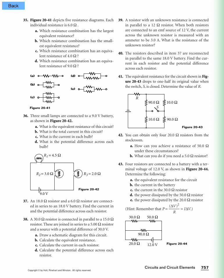
35. Figure 20-41 depicts five resistance diagrams. Eachindividual resistance is 6.0 Ω .
a. Which resistance combination has the largestequivalent resistance?
b. Which resistance combination has the small-est equivalent resistance?
c. Which resistance combination has an equiva-lent resistance of 4.0 Ω ?
d. Which resistance combination has an equiva-lent resistance of 9.0 Ω ?
36. Three small lamps are connected to a 9.0 V battery,as shown in Figure 20-42.
a. What is the equivalent resistance of this circuit?b. What is the total current in this circuit?c. What is the current in each bulb?d. What is the potential difference across each
bulb?
37. An 18.0 Ω resistor and a 6.0 Ω resistor are connect-ed in series to an 18.0 V battery. Find the current inand the potential difference across each resistor.
38. A 30.0 Ω resistor is connected in parallel to a 15.0 Ωresistor. These are joined in series to a 5.00 Ω resistorand a source with a potential difference of 30.0 V.
a. Draw a schematic diagram for this circuit.b. Calculate the equivalent resistance.c. Calculate the current in each resistor.d. Calculate the potential difference across each
resistor.
R1 = 4.5 Ω
R2 = 3.0 Ω R3 = 2.0 Ω
9.0 V
Figure 20-41
(a) (d)
(b)(e)
(c)
39. A resistor with an unknown resistance is connectedin parallel to a 12 Ω resistor. When both resistorsare connected to an emf source of 12 V, the currentacross the unknown resistor is measured with anammeter to be 3.0 A. What is the resistance of theunknown resistor?
40. The resistors described in item 37 are reconnectedin parallel to the same 18.0 V battery. Find the cur-rent in each resistor and the potential differenceacross each resistor.
41. The equivalent resistance for the circuit shown in Fig-ure 20-43 drops to one-half its original value whenthe switch, S, is closed. Determine the value of R.
42. You can obtain only four 20.0 Ω resistors from thestockroom.
a. How can you achieve a resistance of 50.0 Ωunder these circumstances?
b. What can you do if you need a 5.0 Ω resistor?
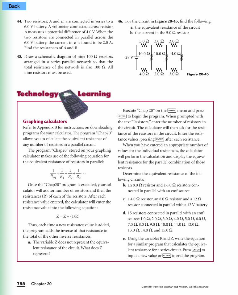
43. Four resistors are connected to a battery with a ter-minal voltage of 12.0 V, as shown in Figure 20-44.Determine the following:
a. the equivalent resistance for the circuitb. the current in the batteryc. the current in the 30.0 Ω resistord. the power dissipated by the 50.0 Ω resistore. the power dissipated by the 20.0 Ω resistor
(Hint: Remember that P = (∆
R
V )2
= I∆V.)
Figure 20-44
30.0 Ω 50.0 Ω
90.0 Ω
20.0 Ω 12.0 V
Figure 20-43
R
S90.0 Ω
10.0 Ω
10.0 Ω
90.0 Ω
Figure 20-42
Copyright © by Holt, Rinehart and Winston. All rights reserved.Chapter 20758
44. Two resistors, A and B, are connected in series to a6.0 V battery. A voltmeter connected across resistorA measures a potential difference of 4.0 V. When thetwo resistors are connected in parallel across the 6.0 V battery, the current in B is found to be 2.0 A.Find the resistances of A and B.
45. Draw a schematic diagram of nine 100 Ω resistorsarranged in a series-parallel network so that thetotal resistance of the network is also 100 Ω. Allnine resistors must be used.
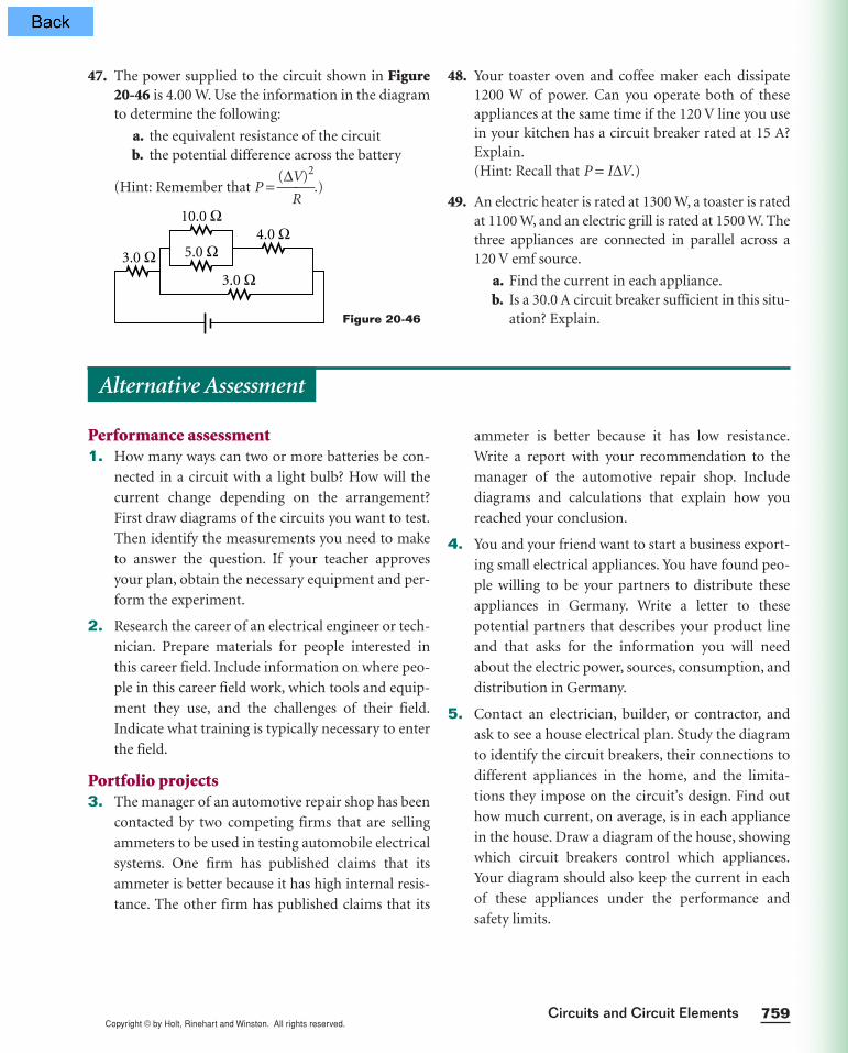
46. For the circuit in Figure 20-45, find the following:
a. the equivalent resistance of the circuitb. the current in the 5.0 Ω resistor
Figure 20-45
5.0 Ω 3.0 Ω 3.0 Ω
4.0 Ω
10.0 Ω10.0 Ω
2.0 Ω 3.0 Ω
28 V4.0 Ω
Execute “Chap 20” on the p menu and press
e to begin the program. When prompted with
the text “Resistors,” enter the number of resistors in
the circuit. The calculator will then ask for the resis-
tance of the resistors in the circuit. Enter the resis-
tance values, pressing e after each resistance.
When you have entered an appropriate number of
values for the individual resistances, the calculator
will perform the calculation and display the equiva-
lent resistance for the parallel combination of those
resistors.
Determine the equivalent resistance of the fol-
lowing circuits:
b. an 8.0 Ω resistor and a 6.0 Ω resistors con-
nected in parallel with an emf source
c. a 4.0 Ω resistor, an 8.0 Ω resistor, and a 12 Ωresistor connected in parallel with a 12 V battery
d. 15 resistors connected in parallel with an emf
source: 1.0 Ω, 2.0 Ω, 3.0 Ω, 4.0 Ω, 5.0 Ω, 6.0 Ω,
7.0 Ω, 8.0 Ω, 9.0 Ω, 10.0 Ω, 11.0 Ω, 12.0 Ω,
13.0 Ω, 14.0 Ω, and 15.0 Ω
e. Using the variables R and Z, write the equation
for a similar program that calculates the equiva-
lent resistance for a series circuit. Press e to
input a new value or ı to end the program.
Graphing calculatorsRefer to Appendix B for instructions on downloading
programs for your calculator. The program “Chap20”
allows you to calculate the equivalent resistance of
any number of resistors in a parallel circuit.
The program “Chap20” stored on your graphing
calculator makes use of the following equation for
the equivalent resistance of resistors in parallel:
R
1
eq =
R
1
1 +
R
1
2 +
R
1
3 . . .
Once the “Chap20” program is executed, your cal-
culator will ask for number of resistors and then the
resistances (R) of each of the resistors. After each
resistance value entered, the calculator will enter the
resistance value into the following equation:
Z = Z + (1/R)
Thus, each time a new resistance value is added,
the program adds the inverse of that resistance to
the total of the other inverse resistances.
a. The variable Z does not represent the equiva-
lent resistance of the circuit. What does Z
represent?
Copyright © by Holt, Rinehart and Winston. All rights reserved.759Circuits and Circuit Elements
47. The power supplied to the circuit shown in Figure20-46 is 4.00 W. Use the information in the diagramto determine the following:
a. the equivalent resistance of the circuitb. the potential difference across the battery
(Hint: Remember that P = (∆
R
V)2
.)
Figure 20-46
3.0 Ω
10.0 Ω
5.0 Ω4.0 Ω
3.0 Ω
48. Your toaster oven and coffee maker each dissipate1200 W of power. Can you operate both of theseappliances at the same time if the 120 V line you usein your kitchen has a circuit breaker rated at 15 A?Explain.(Hint: Recall that P = I∆V.)
49. An electric heater is rated at 1300 W, a toaster is ratedat 1100 W, and an electric grill is rated at 1500 W. Thethree appliances are connected in parallel across a120 V emf source.
a. Find the current in each appliance.b. Is a 30.0 A circuit breaker sufficient in this situ-
ation? Explain.
Performance assessment1. How many ways can two or more batteries be con-
nected in a circuit with a light bulb? How will the
current change depending on the arrangement?
First draw diagrams of the circuits you want to test.
Then identify the measurements you need to make
to answer the question. If your teacher approves
your plan, obtain the necessary equipment and per-
form the experiment.
2. Research the career of an electrical engineer or tech-
nician. Prepare materials for people interested in
this career field. Include information on where peo-
ple in this career field work, which tools and equip-
ment they use, and the challenges of their field.
Indicate what training is typically necessary to enter
the field.
Portfolio projects3. The manager of an automotive repair shop has been
contacted by two competing firms that are selling
ammeters to be used in testing automobile electrical
systems. One firm has published claims that its
ammeter is better because it has high internal resis-
tance. The other firm has published claims that its
ammeter is better because it has low resistance.
Write a report with your recommendation to the
manager of the automotive repair shop. Include
diagrams and calculations that explain how you
reached your conclusion.
4. You and your friend want to start a business export-
ing small electrical appliances. You have found peo-
ple willing to be your partners to distribute these
appliances in Germany. Write a letter to these
potential partners that describes your product line
and that asks for the information you will need
about the electric power, sources, consumption, and
distribution in Germany.
5. Contact an electrician, builder, or contractor, and
ask to see a house electrical plan. Study the diagram
to identify the circuit breakers, their connections to
different appliances in the home, and the limita-
tions they impose on the circuit’s design. Find out
how much current, on average, is in each appliance
in the house. Draw a diagram of the house, showing
which circuit breakers control which appliances.
Your diagram should also keep the current in each
of these appliances under the performance and
safety limits.
Alternative Assessment
Copyright © by Holt, Rinehart and Winston. All rights reserved.Chapter 20760
RESISTORS IN SERIES AND IN PARALLELIn this lab, you will compare the circuits created by wiring two unknown resis-
tors first in series and then in parallel. By taking measurements of the current
in and the potential difference (voltage) across the resistors, and the potential
difference across the whole circuit, you will find the value of the resistance of
each resistor and the equivalent resistance for both resistors to compare the
total current in each circuit.
PREPARATION
1. Determine whether you will be using the CBL and sensors procedure or
the meters procedure. Read the entire lab for the appropriate procedure,
and plan what steps you will take.
2. Prepare a data table in your lab notebook with six columns and three
rows. In the first column, label the second row Series and the third row
Parallel. In the first row, label the second through sixth columns ∆VT,
∆V1, I1, ∆V2, and I2.
Meters procedure begins on page 762.
CHAPTER 20Laboratory Exercise
OBJECTIVES
•Measure current in andpotential differenceacross resistors inseries and in parallel.
•Find the unknown resis-tances of two resistors.
•Calculate equivalentresistances.
•Analyze the relation-ships between potentialdifference, current, andresistance in a circuit.
MATERIALS LIST 2 resistors insulated connecting wire power supply switch
PROCEDURE
CBL AND SENSORS
2 CBL-DIN adapters CBL current and voltage probe
system with amplifier box graphing calculator with link
cable
METERS
2 multimeters, or 1 dc ammeter and 1 voltmeter
SAFETY
• Never close a circuit until it has been approved by your teacher.
• Never rewire or adjust any element of a closed circuit.
• Never work with electricity near water; be sure the floor and all worksurfaces are dry.
• If the pointer on any kind of meter moves off scale, open the circuitimmediately by opening the switch.
• Do not attempt this exercise with any batteries or electrical devicesother than those provided by your teacher for this purpose.
• Use a hot mitt to handle resistors, light sources, and other equipmentthat may be hot. Allow all equipment to cool before storing it.
Copyright © by Holt, Rinehart and Winston. All rights reserved.
Copyright © by Holt, Rinehart and Winston. All rights reserved.761Circuits and Circuit Elements
Resistors in series
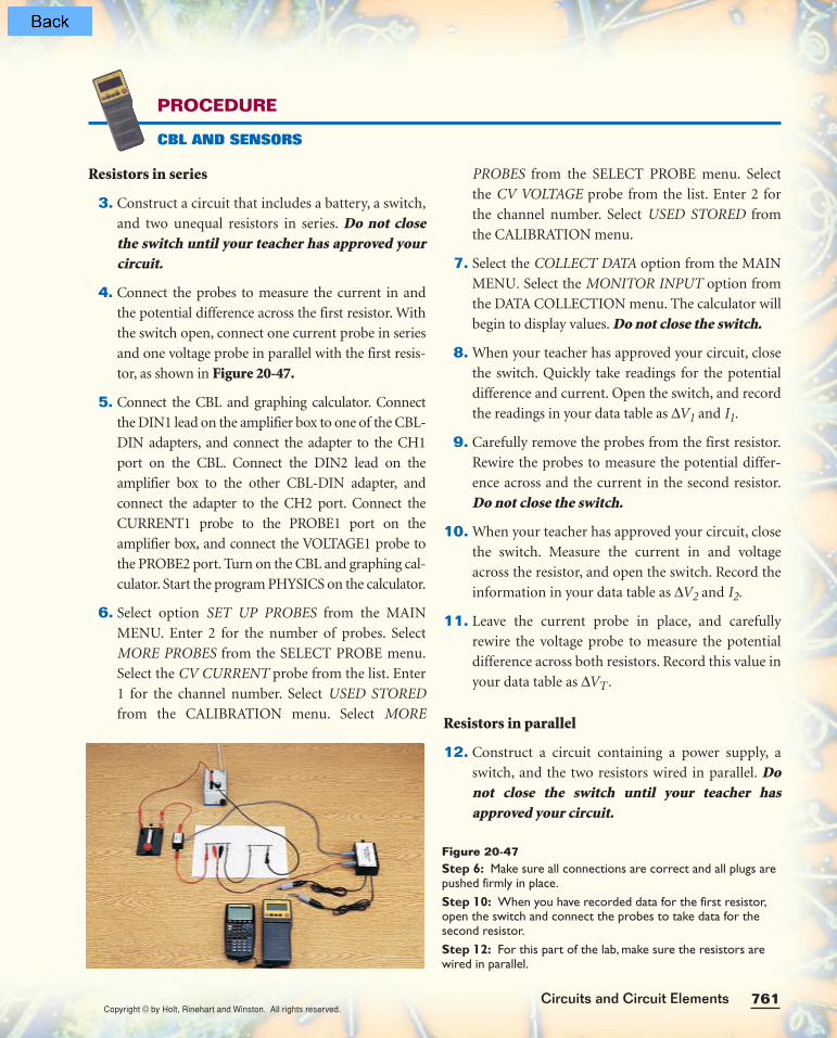
3. Construct a circuit that includes a battery, a switch,
and two unequal resistors in series. Do not closethe switch until your teacher has approved yourcircuit.
4. Connect the probes to measure the current in and
the potential difference across the first resistor. With
the switch open, connect one current probe in series
and one voltage probe in parallel with the first resis-
tor, as shown in Figure 20-47.
5. Connect the CBL and graphing calculator. Connect
the DIN1 lead on the amplifier box to one of the CBL-
DIN adapters, and connect the adapter to the CH1
port on the CBL. Connect the DIN2 lead on the
amplifier box to the other CBL-DIN adapter, and
connect the adapter to the CH2 port. Connect the
CURRENT1 probe to the PROBE1 port on the
amplifier box, and connect the VOLTAGE1 probe to
the PROBE2 port. Turn on the CBL and graphing cal-
culator. Start the program PHYSICS on the calculator.
6. Select option SET UP PROBES from the MAIN
MENU. Enter 2 for the number of probes. Select
MORE PROBES from the SELECT PROBE menu.
Select the CV CURRENT probe from the list. Enter
1 for the channel number. Select USED STORED
from the CALIBRATION menu. Select MORE
PROBES from the SELECT PROBE menu. Select
the CV VOLTAGE probe from the list. Enter 2 for
the channel number. Select USED STORED from
the CALIBRATION menu.
7. Select the COLLECT DATA option from the MAIN
MENU. Select the MONITOR INPUT option from
the DATA COLLECTION menu. The calculator will
begin to display values. Do not close the switch.
8. When your teacher has approved your circuit, close
the switch. Quickly take readings for the potential
difference and current. Open the switch, and record
the readings in your data table as ∆V1 and I1.
9. Carefully remove the probes from the first resistor.
Rewire the probes to measure the potential differ-
ence across and the current in the second resistor.
Do not close the switch.
10. When your teacher has approved your circuit, close
the switch. Measure the current in and voltage
across the resistor, and open the switch. Record the
information in your data table as ∆V2 and I2.
11. Leave the current probe in place, and carefully
rewire the voltage probe to measure the potential
difference across both resistors. Record this value in
your data table as ∆VT.
Resistors in parallel
12. Construct a circuit containing a power supply, a
switch, and the two resistors wired in parallel. Donot close the switch until your teacher hasapproved your circuit.
PROCEDURE
CBL AND SENSORS
Figure 20-47Step 6: Make sure all connections are correct and all plugs arepushed firmly in place.Step 10: When you have recorded data for the first resistor,open the switch and connect the probes to take data for thesecond resistor.Step 12: For this part of the lab, make sure the resistors arewired in parallel.
Copyright © by Holt, Rinehart and Winston. All rights reserved.

Copyright © by Holt, Rinehart and Winston. All rights reserved.Chapter 20762
13. With the switch open, connect the current probe in
series and the voltage probe in parallel with one of
the resistors. Do not close the switch.
14. When your teacher has approved your circuit, close
the switch. Quickly record the readings for the volt-
age and current in your data table. Open the switch.
15. Rewire the probes to measure the potential differ-
ence across and the current in the second resistor.
Do not close the switch.
16. When your teacher has approved your circuit, close
the switch. Measure the current in and potential
difference across the resistor, and record the infor-
mation in your data table. Open the switch.
17. Leave the current probe in place, and carefully
rewire the voltage probe to measure the potential
difference across the power supply. Record this
value in your data table as ∆VT.
Analysis and Interpretation begins on page 763.
Resistors in series
3. Construct a circuit that includes a battery, a switch,
and two unequal resistors in series. Do not closethe switch until your teacher has approved your circuit.
4. With the switch open, connect the current meter in
series and the voltage meter in parallel with one of
the resistors. Do not close the switch.
5. When your teacher has approved your circuit, close
the switch. Measure the current in and the potential
difference across the resistor. Record the informa-
tion in your data table. Open the switch.
6. Carefully remove the meters from the first resis-
tor. Rewire the meters to measure the potential
difference across and the current in the second
resistor. Do not close the switch.
7. When your teacher has approved your circuit, close
the switch. Measure the current in and potential
difference across the resistor, and record the infor-
mation in your data table. Open the switch.
8. Leave the current meter in place, and carefully
rewire the voltage meter to measure the potential
difference across both resistors. Record this value in
your data table as ∆VT.
Resistors in parallel
9. Construct a circuit containing a power supply, a
switch, and the two resistors wired in parallel, as
shown in Figure 20-48. Do not close the switchuntil your teacher has approved your circuit.
10. With the switch open, connect the current meter in
series and the voltage meter in parallel with one of
the resistors. Do not close the switch.
PROCEDURE
METERS
Figure 20-48Step 4: Make sure all connections are correct. For this part ofthe lab, make sure the resistors are wired in series.Step 7: When you have recorded data for the first resistor,open the switch and connect the probes to take data for thesecond resistor.Step 9: For this part of the lab, make sure the resistors arewired in parallel, as shown in Figure 20-48.
Copyright © by Holt, Rinehart and Winston. All rights reserved.

Copyright © by Holt, Rinehart and Winston. All rights reserved.763Circuits and Circuit Elements
ANALYSIS AND INTERPRETATION
Calculations and data analysis
1. Analyzing data Using your measurements for potential difference and
current, compute the resistance values of R1 and R2 in each circuit.
2. Comparing results Compare your results from item 1 for the different
circuits.
a. Do R1 and R2 have the same values in each circuit?
b. Did you expect R1 and R2 to have the same values? Explain. If the
results are different, explain what may have caused the difference.
3. Analyzing data Compute the equivalent resistance Req using the values
found in item 1 for each circuit.
Conclusions
4. Comparing results Based on your calculations in item 3, did the two
resistors provide the same equivalent resistance in both circuits? If not,
which combination had the greater resistance? Explain how the combi-
nation of resistors affects the total resistance in the circuit.
5. Analyzing data Compute the total current in each circuit using the
calculated value for Req and the measured value for ∆VT.
6. Comparing results Based on your calculations in item 5, do both cir-
cuits have the same total current? If not, which circuit has the greater
current? Explain how the combination of resistors affects the total cur-
rent in the circuit.
7. Analyzing information Compare the total current in each circuit with
the current in each resistor. What is the relationship between the current
in an individual resistor and the total current in the circuit?
8. Organizing conclusions For each circuit, compare the potential dif-
ference across each resistor with ∆VT. What is the relationship?
11. When your teacher has approved your circuit, close
the switch. Measure the current in and potential
difference across the resistor, and record the infor-
mation in your data table. Open the switch.
12. Rewire the meters to measure the potential differ-
ence across and current in the second resistor. Donot close the switch until your teacher hasapproved your circuit.
13. When your teacher has approved your circuit, close
the switch. Measure the current in and potential
difference across the resistor, and record the infor-
mation in your data table. Open the switch.
14. Leave the current meter in place, and carefully
rewire the voltage meter to measure the potential
difference across the power supply. Record this
value in your data table as ∆VT.
Copyright © by Holt, Rinehart and Winston. All rights reserved.