copyright © by holt, rinehart and winston. all rights ...landerson.net/holt...
TRANSCRIPT

Copyright © by Holt, Rinehart and Winston. All rights reserved.Copyright © by Holt, Rinehart and Winston. All rights reserved.

Copyright © by Holt, Rinehart and Winston. All rights reserved.
PHYSICS IN ACTION
In an electric guitar, the vibrations of the
strings are converted to an electric signal,
which is then amplified outside the guitar
and heard as sound from a loudspeaker.
Yet the electric guitar is not plugged
directly into an electric source. Instead, it
generates electric current by a process
called induction. By changing the magnetic
field near a coil of wire, an electric current
can be induced in the coil by the vibrations
of the guitar strings.
This chapter explores how induction
produces and changes alternating currents.
• Why does the generated current last only aslong as the string vibrates?
• Why must the strings be ferromagnetic inorder for an electric guitar to work?
CONCEPT REVIEW
Resistance (Section 19–2)
emf (Section 20–1)
Magnetic force (Section 21–3)
CHAPTER 22
Induction andAlternatingCurrent
Induction and Alternating Current 793Copyright © by Holt, Rinehart and Winston. All rights reserved.
Copyright © by Holt, Rinehart and Winston. All rights reserved.Chapter 22794
MAGNETIC FIELDS AND INDUCED EMFS
Recall that in Chapter 20 you were asked if it was possible to produce an elec-
tric current using only wires and no battery. So far, all electric circuits that you
have studied have used a battery or an electrical power supply to create a
potential difference within a circuit. In both of these cases, an emf increases
the electrical potential energy of charges in the circuit, causing them to move
through the circuit and create a current.
It is also possible to induce a current in a circuit without the use of a battery
or an electrical power supply. Just as a magnetic field can be formed by a cur-
rent in a circuit, a current can be formed by moving a portion of a closed elec-
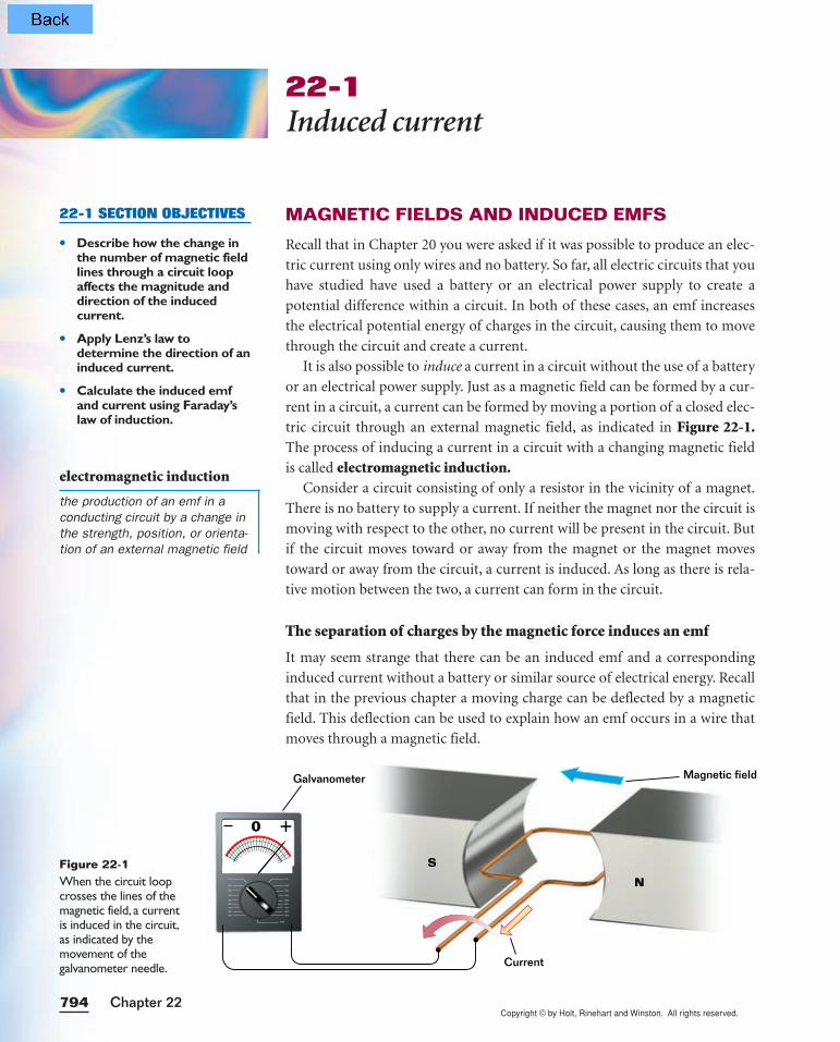
tric circuit through an external magnetic field, as indicated in Figure 22-1.The process of inducing a current in a circuit with a changing magnetic field
is called electromagnetic induction.Consider a circuit consisting of only a resistor in the vicinity of a magnet.
There is no battery to supply a current. If neither the magnet nor the circuit is
moving with respect to the other, no current will be present in the circuit. But
if the circuit moves toward or away from the magnet or the magnet moves
toward or away from the circuit, a current is induced. As long as there is rela-
tive motion between the two, a current can form in the circuit.
The separation of charges by the magnetic force induces an emf
It may seem strange that there can be an induced emf and a corresponding
induced current without a battery or similar source of electrical energy. Recall
that in the previous chapter a moving charge can be deflected by a magnetic
field. This deflection can be used to explain how an emf occurs in a wire that
moves through a magnetic field.
22-1Induced current
22-1 SECTION OBJECTIVES
• Describe how the change inthe number of magnetic fieldlines through a circuit loopaffects the magnitude anddirection of the inducedcurrent.
• Apply Lenz’s law todetermine the direction of aninduced current.
• Calculate the induced emfand current using Faraday’slaw of induction.
electromagnetic induction
the production of an emf in aconducting circuit by a change inthe strength, position, or orienta-tion of an external magnetic field
Figure 22-1When the circuit loopcrosses the lines of themagnetic field, a current is induced in the circuit,as indicated by the movement of the galvanometer needle.
100
200
300
400
500
600
700
800
900
100
200
300
400
500
600
700
800
900
1000
Magnetic fieldGalvanometer
N
S
0
Current
Copyright © by Holt, Rinehart and Winston. All rights reserved.795Induction and Alternating Current
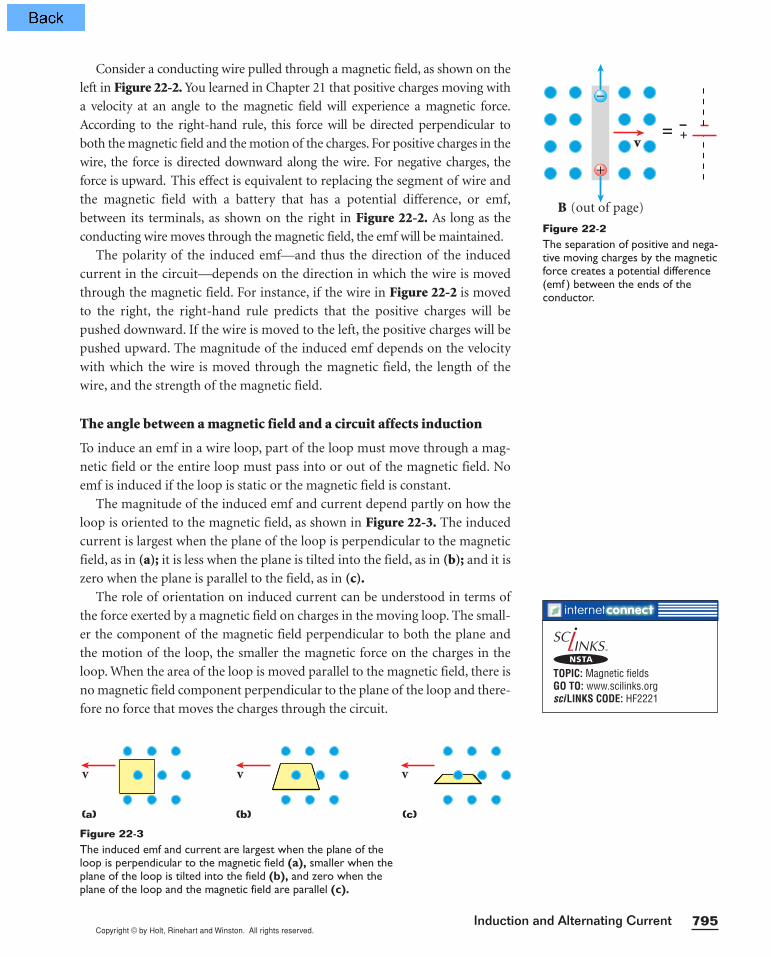
Consider a conducting wire pulled through a magnetic field, as shown on the
left in Figure 22-2. You learned in Chapter 21 that positive charges moving with
a velocity at an angle to the magnetic field will experience a magnetic force.
According to the right-hand rule, this force will be directed perpendicular to
both the magnetic field and the motion of the charges. For positive charges in the
wire, the force is directed downward along the wire. For negative charges, the
force is upward. This effect is equivalent to replacing the segment of wire and
the magnetic field with a battery that has a potential difference, or emf,
between its terminals, as shown on the right in Figure 22-2. As long as the
conducting wire moves through the magnetic field, the emf will be maintained.
The polarity of the induced emf—and thus the direction of the induced
current in the circuit—depends on the direction in which the wire is moved
through the magnetic field. For instance, if the wire in Figure 22-2 is moved
to the right, the right-hand rule predicts that the positive charges will be
pushed downward. If the wire is moved to the left, the positive charges will be
pushed upward. The magnitude of the induced emf depends on the velocity
with which the wire is moved through the magnetic field, the length of the
wire, and the strength of the magnetic field.
The angle between a magnetic field and a circuit affects induction
To induce an emf in a wire loop, part of the loop must move through a mag-
netic field or the entire loop must pass into or out of the magnetic field. No
emf is induced if the loop is static or the magnetic field is constant.
The magnitude of the induced emf and current depend partly on how the
loop is oriented to the magnetic field, as shown in Figure 22-3. The induced
current is largest when the plane of the loop is perpendicular to the magnetic
field, as in (a); it is less when the plane is tilted into the field, as in (b); and it is
zero when the plane is parallel to the field, as in (c).The role of orientation on induced current can be understood in terms of
the force exerted by a magnetic field on charges in the moving loop. The small-
er the component of the magnetic field perpendicular to both the plane and
the motion of the loop, the smaller the magnetic force on the charges in the
loop. When the area of the loop is moved parallel to the magnetic field, there is
no magnetic field component perpendicular to the plane of the loop and there-
fore no force that moves the charges through the circuit.
B (out of page)
v=
−
+
–+
Figure 22-2The separation of positive and nega-tive moving charges by the magneticforce creates a potential difference(emf ) between the ends of the conductor.
vv v
(a) (b) (c)
Figure 22-3The induced emf and current are largest when the plane of theloop is perpendicular to the magnetic field (a), smaller when theplane of the loop is tilted into the field (b), and zero when theplane of the loop and the magnetic field are parallel (c).
TOPIC: Magnetic fieldsGO TO: www.scilinks.orgsciLINKS CODE: HF2221
NSTA
Copyright © by Holt, Rinehart and Winston. All rights reserved.
In 1996, the space shuttle Columbiaattempted to use a 20.7 km con-ducting tether to study Earth’s mag-netic field in space. The plan was todrag the tether through the mag-netic field, inducing an emf in thetether. The magnitude of the emfwould directly vary with thestrength of the magnetic field.Unfortunately, the tether brokebefore it was fully extended, so theexperiment was abandoned.
Chapter 22796
Change in the number of magnetic field lines induces a current
So far, you have learned that moving a circuit loop into or out of a magnetic
field can induce an emf and a current in the circuit. Changing the size of the
loop or the strength of the magnetic field also will induce an emf in the circuit.
One way to predict whether a current will be induced in a given situation
involves the concept of changes in magnetic field lines. For example, moving
the circuit into the magnetic field causes some lines to move into the loop.
Changing the size of the circuit loop or rotating the loop changes the number
of field lines passing through the loop, as does changing the magnetic field’s
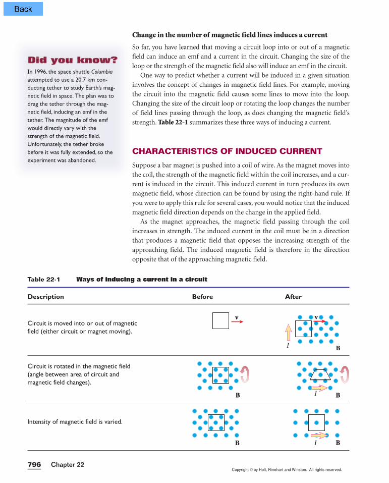
strength. Table 22-1 summarizes these three ways of inducing a current.
CHARACTERISTICS OF INDUCED CURRENT
Suppose a bar magnet is pushed into a coil of wire. As the magnet moves into
the coil, the strength of the magnetic field within the coil increases, and a cur-
rent is induced in the circuit. This induced current in turn produces its own
magnetic field, whose direction can be found by using the right-hand rule. If
you were to apply this rule for several cases, you would notice that the induced
magnetic field direction depends on the change in the applied field.
As the magnet approaches, the magnetic field passing through the coil
increases in strength. The induced current in the coil must be in a direction
that produces a magnetic field that opposes the increasing strength of the
approaching field. The induced magnetic field is therefore in the direction
opposite that of the approaching magnetic field.
Table 22-1 Ways of inducing a current in a circuit
Description Before After
Circuit is moved into or out of magneticfield (either circuit or magnet moving).
Circuit is rotated in the magnetic field(angle between area of circuit andmagnetic field changes).
Intensity of magnetic field is varied.
v
B
B
B
v
I
I B
BI
Copyright © by Holt, Rinehart and Winston. All rights reserved.
Approachingmagnetic field
Magnetic field frominduced currentInduced current
Wire
NS
v
N S
Recedingmagnetic field
Magnetic field frominduced currentInduced current
Wire
v
N SSN
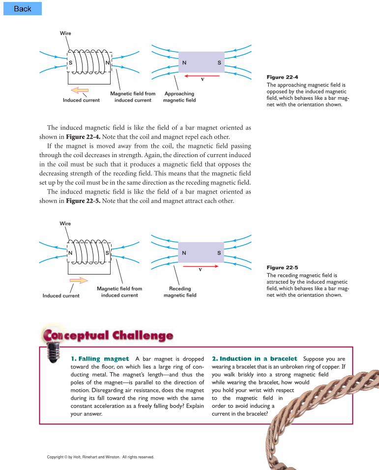
Figure 22-4The approaching magnetic field isopposed by the induced magneticfield, which behaves like a bar mag-net with the orientation shown.
Figure 22-5The receding magnetic field isattracted by the induced magneticfield, which behaves like a bar mag-net with the orientation shown.
1. Falling magnet A bar magnet is droppedtoward the floor, on which lies a large ring of con-ducting metal. The magnet’s length—and thus thepoles of the magnet—is parallel to the direction ofmotion. Disregarding air resistance, does the magnetduring its fall toward the ring move with the sameconstant acceleration as a freely falling body? Explainyour answer.
2. Induction in a bracelet Suppose you arewearing a bracelet that is an unbroken ring of copper. Ifyou walk briskly into a strong magnetic field while wearing the bracelet, how would you hold your wrist with respect to the magnetic field in order to avoid inducing a current in the bracelet?
The induced magnetic field is like the field of a bar magnet oriented as
shown in Figure 22-4. Note that the coil and magnet repel each other.
If the magnet is moved away from the coil, the magnetic field passing
through the coil decreases in strength. Again, the direction of current induced
in the coil must be such that it produces a magnetic field that opposes the
decreasing strength of the receding field. This means that the magnetic field
set up by the coil must be in the same direction as the receding magnetic field.
The induced magnetic field is like the field of a bar magnet oriented as
shown in Figure 22-5. Note that the coil and magnet attract each other.
Copyright © by Holt, Rinehart and Winston. All rights reserved.Chapter 22798
The rule for finding the direction of the induced current is called Lenz’s law
and is expressed as follows:
The magnetic field of the induced current opposes the change in the applied
magnetic field.
Note that the field of the induced current does not oppose the applied field
but rather the change in the applied field. If the applied field changes, the
induced field attempts to keep the total field strength constant, according to
the principle of energy conservation.
Faraday’s law of induction
Because of the principle of energy conservation, Lenz’s law allows you to deter-
mine the direction of an induced current in a circuit. Lenz’s law does not provide
information on the magnitude of the induced current or the induced emf. To
calculate the magnitude of the induced emf, you must use Faraday’s law of mag-
netic induction. For a single loop of a circuit, this may be expressed as follows:
emf = − ∆[AB
∆(c
t
os q)]
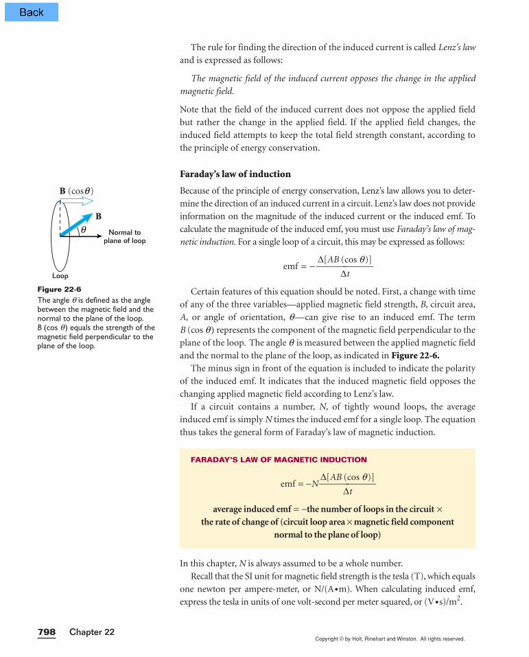
Certain features of this equation should be noted. First, a change with time
of any of the three variables—applied magnetic field strength, B, circuit area,
A, or angle of orientation, q—can give rise to an induced emf. The term
B (cos q) represents the component of the magnetic field perpendicular to the
plane of the loop. The angle q is measured between the applied magnetic field
and the normal to the plane of the loop, as indicated in Figure 22-6.The minus sign in front of the equation is included to indicate the polarity
of the induced emf. It indicates that the induced magnetic field opposes the
changing applied magnetic field according to Lenz’s law.
If a circuit contains a number, N, of tightly wound loops, the average
induced emf is simply N times the induced emf for a single loop. The equation
thus takes the general form of Faraday’s law of magnetic induction.
In this chapter, N is always assumed to be a whole number.
Recall that the SI unit for magnetic field strength is the tesla (T), which equals
one newton per ampere-meter, or N/(A•m). When calculating induced emf,
express the tesla in units of one volt-second per meter squared, or (V•s)/m2.
FARADAY’S LAW OF MAGNETIC INDUCTION
emf = −N∆[AB
∆(c
t
os q)]
average induced emf = −the number of loops in the circuit × the rate of change of (circuit loop area × magnetic field component
normal to the plane of loop)
B
Normal toplane of loop
Loop
θ
B (cos )θ
Figure 22-6The angle q is defined as the anglebetween the magnetic field and thenormal to the plane of the loop.B (cos q ) equals the strength of themagnetic field perpendicular to theplane of the loop.
Copyright © by Holt, Rinehart and Winston. All rights reserved.799Induction and Alternating Current
SAMPLE PROBLEM 22A
Induced emf and current
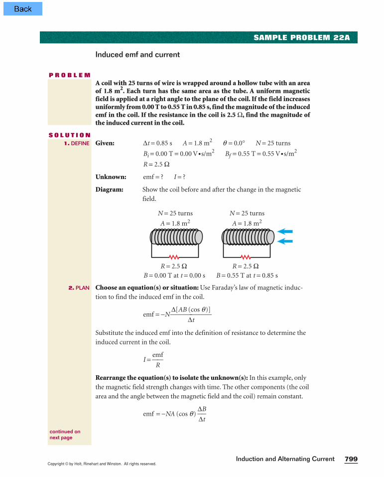
P R O B L E MA coil with 25 turns of wire is wrapped around a hollow tube with an areaof 1.8 m2. Each turn has the same area as the tube. A uniform magneticfield is applied at a right angle to the plane of the coil. If the field increasesuniformly from 0.00 T to 0.55 T in 0.85 s, find the magnitude of the inducedemf in the coil. If the resistance in the coil is 2.5 Ω, find the magnitude ofthe induced current in the coil.
S O L U T I O NGiven: ∆t = 0.85 s A = 1.8 m2 q = 0.0° N = 25 turns
Bi = 0.00 T = 0.00 V•s/m2 Bf = 0.55 T = 0.55 V•s/m2
R = 2.5 Ω
Unknown: emf = ? I = ?
Diagram: Show the coil before and after the change in the magnetic
field.
Choose an equation(s) or situation: Use Faraday’s law of magnetic induc-
tion to find the induced emf in the coil.
emf = −N ∆[AB
∆(c
t
os q)]
Substitute the induced emf into the definition of resistance to determine the
induced current in the coil.
I = em
R
f
Rearrange the equation(s) to isolate the unknown(s): In this example, only
the magnetic field strength changes with time. The other components (the coil
area and the angle between the magnetic field and the coil) remain constant.
emf = −NA (cos q) ∆∆
B
t
N = 25 turns
B = 0.00 T at t = 0.00 s B = 0.55 T at t = 0.85 s
A = 1.8 m2
R = 2.5 Ω
N = 25 turns
A = 1.8 m2
R = 2.5 Ω
1. DEFINE
2. PLAN
continued onnext page

Copyright © by Holt, Rinehart and Winston. All rights reserved.Chapter 22800
Substitute the values into the equation(s) and solve:
emf = −(25)(1.8 m2)(cos 0.0°) = −29 V
I = −2
2
.5
9
ΩV
= −12 A
The induced emf, and therefore the induced current, are directed through the
coil so that the magnetic field produced by the induced current opposes the
change in the applied magnetic field. For the diagram shown on page 799, the
induced magnetic field is directed to the right and the current that produces
it is directed from left to right through the resistor.
emf = −29 V
I = −12 A
(0.55 − 0.00) V
m
•2s
(0.85 s)
3. CALCULATE
4. EVALUATE
CALCULATOR SOLUTION
Because the minimum number of significant figures for the data is two,the calculator answer, 29.11764706,should be rounded to two digits.
1. A single circular loop with a radius of 22 cm is placed in a uniform exter-
nal magnetic field with a strength of 0.50 T so that the plane of the coil is
perpendicular to the field. The coil is pulled steadily out of the field in
0.25 s. Find the average induced emf during this interval.
2. A coil with 205 turns of wire, a total resistance of 23 Ω, and a cross-
sectional area of 0.25 m2 is positioned with its plane perpendicular to the
field of a powerful electromagnet. What average current is induced in the
coil during the 0.25 s that the magnetic field drops from 1.6 T to 0.0 T?
3. A circular wire loop with a radius of 0.33 m is located in an external
magnetic field of strength +0.35 T that is perpendicular to the plane of
the loop. The field strength changes to −0.25 T in 1.5 s. (The plus and
minus signs for a magnetic field refer to opposite directions through the
coil.) Find the magnitude of the average induced emf during this interval.
4. A 505-turn circular-loop coil with a diameter of 15.5 cm is initially
aligned so that its plane is perpendicular to the Earth’s magnetic field. In
2.77 ms the coil is rotated 90.0° so that its plane is parallel to the Earth’s
magnetic field. If an average emf of 0.166 V is induced in the coil, what is
the value of the Earth’s magnetic field?
Induced emf and current
PRACTICE 22A
Copyright © by Holt, Rinehart and Winston. All rights reserved.801Induction and Alternating Current
APPLICATIONS OF INDUCTION
In electric circuits, the need often arises for a temporary or continuously
changing current to be produced. This kind of current can be generated
through electromagnetic induction.
Door bells
Certain types of door bells chime when the button is briefly
pushed. A hint to how these door bells work is the small electric
light bulb often found behind the doorbell button. When you
press the button, the light briefly goes out. This indicates that
the door bell’s circuit has been opened and that the current has
been temporarily discontinued.
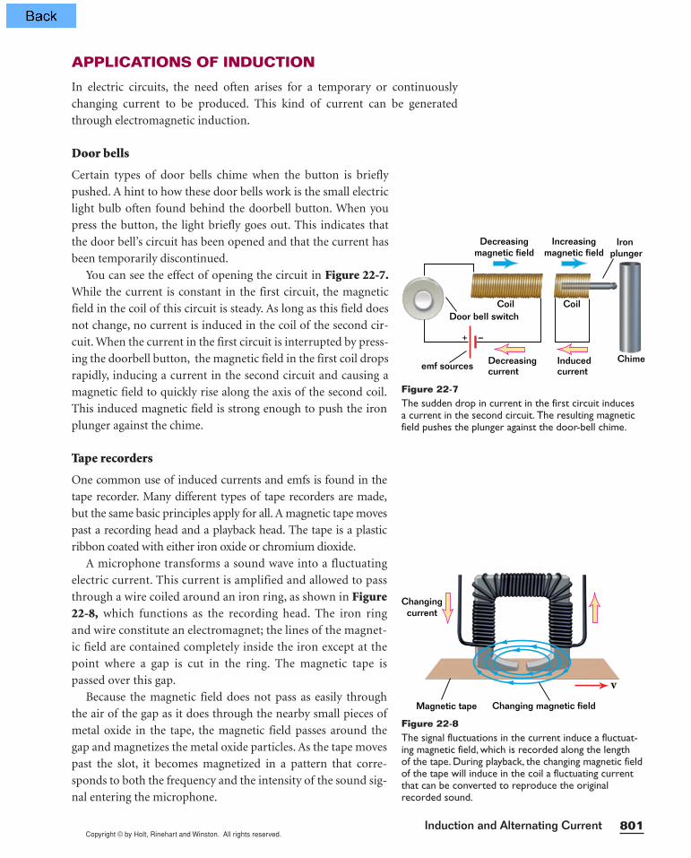
You can see the effect of opening the circuit in Figure 22-7.While the current is constant in the first circuit, the magnetic
field in the coil of this circuit is steady. As long as this field does
not change, no current is induced in the coil of the second cir-
cuit. When the current in the first circuit is interrupted by press-
ing the doorbell button, the magnetic field in the first coil drops
rapidly, inducing a current in the second circuit and causing a
magnetic field to quickly rise along the axis of the second coil.
This induced magnetic field is strong enough to push the iron
plunger against the chime.
Tape recorders
One common use of induced currents and emfs is found in the
tape recorder. Many different types of tape recorders are made,
but the same basic principles apply for all. A magnetic tape moves
past a recording head and a playback head. The tape is a plastic
ribbon coated with either iron oxide or chromium dioxide.
A microphone transforms a sound wave into a fluctuating
electric current. This current is amplified and allowed to pass
through a wire coiled around an iron ring, as shown in Figure22-8, which functions as the recording head. The iron ring
and wire constitute an electromagnet; the lines of the magnet-
ic field are contained completely inside the iron except at the
point where a gap is cut in the ring. The magnetic tape is
passed over this gap.
Because the magnetic field does not pass as easily through
the air of the gap as it does through the nearby small pieces of
metal oxide in the tape, the magnetic field passes around the
gap and magnetizes the metal oxide particles. As the tape moves
past the slot, it becomes magnetized in a pattern that corre-
sponds to both the frequency and the intensity of the sound sig-
nal entering the microphone.
–
Decreasingcurrentemf sources
Increasingmagnetic field
Decreasingmagnetic field
Inducedcurrent
Door bell switchCoil Coil
Chime
Iron plunger
+
Figure 22-7The sudden drop in current in the first circuit induces a current in the second circuit. The resulting magneticfield pushes the plunger against the door-bell chime.
Magnetic tape
Changingcurrent
v
Changing magnetic field
Figure 22-8The signal fluctuations in the current induce a fluctuat-ing magnetic field, which is recorded along the length of the tape. During playback, the changing magnetic fieldof the tape will induce in the coil a fluctuating currentthat can be converted to reproduce the originalrecorded sound.

Copyright © by Holt, Rinehart and Winston. All rights reserved.Chapter 22802
In the recording process, the magnetic field is produced by an applied cur-
rent. During the playback process, induction is used to create a current from a
changing magnetic field. The sound signal is reconstructed by passing the tape
over the playback head, which is an iron ring with wire wound around it. In
some recorders, one head is used for both playback and recording.
When the tape moves past the playback head, the varying magnetic fields
on the tape produce changing magnetic-field lines through the wire coil,
inducing a current in the coil. The current corresponds to the current in the
recording head that originally produced the recording on the tape. This
changing electric current can be amplified and used to drive a speaker. Play-
back is thus an example of induction of a current by a moving magnet.
Section Review
1. A circular current loop made of flexible wire is located in a magnetic
field. Describe three ways an emf can be induced in the loop.
2. A spacecraft orbiting Earth has a coil of wire in it. An astronaut measures
a small current in the coil, even though there is no battery connected to it
and there are no magnets on the spacecraft. What is causing the current?
3. A bar magnet is positioned near a coil of
wire, as shown in Figure 22-9. What is the
direction of the current through the resis-
tor when the magnet is moved to the
left, as in (a)? to the right, as in (b)?
4. A 256-turn coil with a cross-sectional area of 0.0025 m2 is placed in a
uniform external magnetic field of strength 0.25 T so that the plane of
the coil is perpendicular to the field. The coil is pulled steadily out of the
field in 0.75 s. Find the average induced emf during this interval.
5. Physics in Action Electric guitar strings are made of ferromag-
netic materials that can be magnetized. The strings lie closely over and
perpendicular to a coil of wire. Inside the coil are permanent magnets
that magnetize the segments of the strings overhead. Using this arrange-
ment, explain how the vibrations of a plucked string produce an electric
signal at the same frequency as the vibration of the string.
6. Physics in Action The magnetic field strength of a magnetized
electric guitar string is 9.0 × 10⁻⁴ T. The pickup coil consists of 5200 turns
of wire and has an effective area for each string of 5.4 × 10⁻⁵ m2. If the
string vibrates with a frequency of 440 Hz, what is the average induced
emf? (Hint: Assume the magnetic field strength varies from a minimum
value of 0.0 T to its maximum value during one fourth of the string’s
vibration cycle.)
R
v
v(a)
(b)
S N
Figure 22-9
Copyright © by Holt, Rinehart and Winston. All rights reserved.803Induction and Alternating Current
GENERATORS AND ALTERNATING CURRENT
In the previous section you learned that a current can be induced in a circuit
either by changing the magnetic field strength or by moving the circuit loop
in or out of the magnetic field. Another way to induce a current is to change
the orientation of the loop with respect to the magnetic field.
This second approach to inducing a current represents a practical means of gen-
erating electrical energy. In effect, the mechanical energy used to turn the loop is
converted to electrical energy.A device that does this is called an electric generator.In most commercial power plants, mechanical energy is provided in the form
of rotational motion. For example, in a hydroelectric plant, falling water directed
against the blades of a turbine causes the turbine to turn; in a coal or natural-gas-
burning plant, energy produced by burning fuel is used to convert water to
steam, and this steam is directed against the turbine blades to turn the turbine.
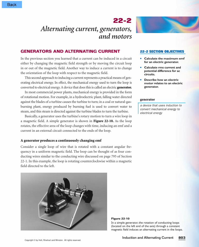
Basically, a generator uses the turbine’s rotary motion to turn a wire loop in
a magnetic field. A simple generator is shown in Figure 22-10. As the loop
rotates, the effective area of the loop changes with time, inducing an emf and a
current in an external circuit connected to the ends of the loop.
A generator produces a continuously changing emf
Consider a single loop of wire that is rotated with a constant angular fre-
quency in a uniform magnetic field. The loop can be thought of as four con-
ducting wires similar to the conducting wire discussed on page 795 of Section
22-1. In this example, the loop is rotating counterclockwise within a magnetic
field directed to the left.
22-2Alternating current, generators,
and motors
22-2 SECTION OBJECTIVES
• Calculate the maximum emffor an electric generator.
• Calculate rms current andpotential difference for accircuits.
• Describe how an electricmotor relates to an electricgenerator.
generator
a device that uses induction toconvert mechanical energy toelectrical energy
Figure 22-10In a simple generator, the rotation of conducting loops(located on the left end of the axis) through a constantmagnetic field induces an alternating current in the loops.
Copyright © by Holt, Rinehart and Winston. All rights reserved.Chapter 22804
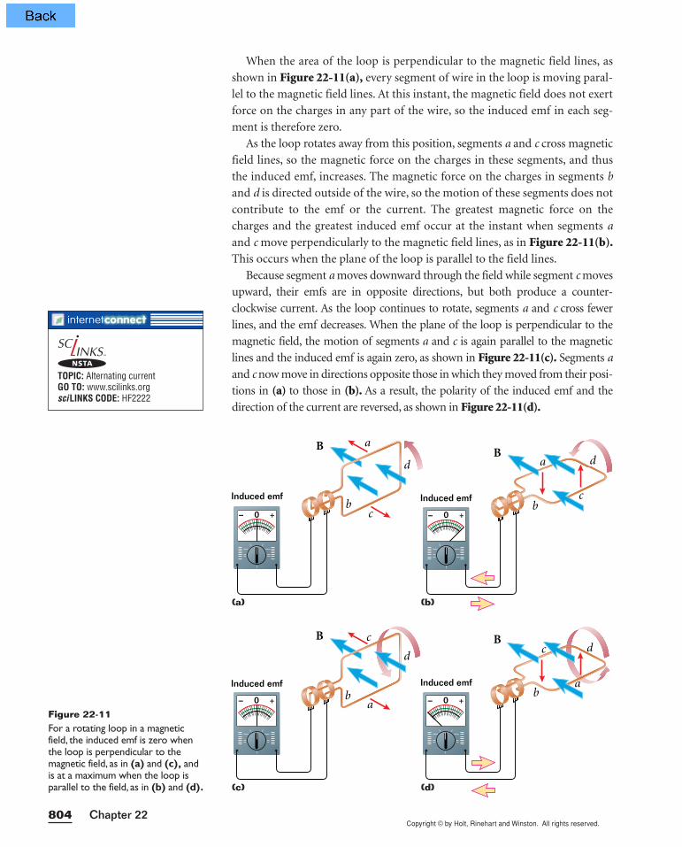
When the area of the loop is perpendicular to the magnetic field lines, as
shown in Figure 22-11(a), every segment of wire in the loop is moving paral-
lel to the magnetic field lines. At this instant, the magnetic field does not exert
force on the charges in any part of the wire, so the induced emf in each seg-
ment is therefore zero.
As the loop rotates away from this position, segments a and c cross magnetic
field lines, so the magnetic force on the charges in these segments, and thus
the induced emf, increases. The magnetic force on the charges in segments b
and d is directed outside of the wire, so the motion of these segments does not
contribute to the emf or the current. The greatest magnetic force on the
charges and the greatest induced emf occur at the instant when segments a
and c move perpendicularly to the magnetic field lines, as in Figure 22-11(b).This occurs when the plane of the loop is parallel to the field lines.
Because segment a moves downward through the field while segment c moves
upward, their emfs are in opposite directions, but both produce a counter-
clockwise current. As the loop continues to rotate, segments a and c cross fewer
lines, and the emf decreases. When the plane of the loop is perpendicular to the
magnetic field, the motion of segments a and c is again parallel to the magnetic
lines and the induced emf is again zero, as shown in Figure 22-11(c). Segments a
and c now move in directions opposite those in which they moved from their posi-
tions in (a) to those in (b). As a result, the polarity of the induced emf and the
direction of the current are reversed, as shown in Figure 22-11(d).
Figure 22-11For a rotating loop in a magneticfield, the induced emf is zero whenthe loop is perpendicular to themagnetic field, as in (a) and (c), andis at a maximum when the loop isparallel to the field, as in (b) and (d).
0 +–
Induced emf
a
d
cb
B
c
a0 +–
Induced emf
d
b
B
a
dc
b
B
0 +–
Induced emf
a d
cb
B
0 +–
Induced emf
(a) (b)
(c) (d)
TOPIC: Alternating currentGO TO: www.scilinks.orgsciLINKS CODE: HF2222
NSTA
Copyright © by Holt, Rinehart and Winston. All rights reserved.805Induction and Alternating Current
emf
Time
Maximumemf
Figure 22-12The change with time of the inducedemf is depicted by a sine wave.
SAMPLE PROBLEM 22B
Induction in generators
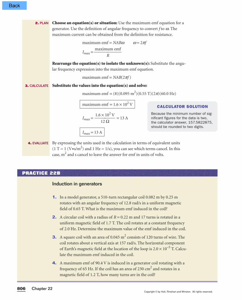
P R O B L E MA generator consists of exactly eight turns of wire, each with an area A = 0.095 m2 and a total resistance of 12 Ω. The loop rotates in a magneticfield of 0.55 T at a constant frequency of 60.0 Hz. Find the maximuminduced emf and maximum induced current in the loop.
S O L U T I O NGiven: f = 60.0 Hz A = 0.095 m2 R = 12 Ω
B = 0.55 T = 0.55 V•s/m2 N = 8
Unknown: maximum emf = ? Imax = ?
Diagram:
N = 8 turns
B = 0.55 T
R = 12 Ω
A = 0.095 m2
f = 60.0 Hz
1. DEFINE
continued onnext page
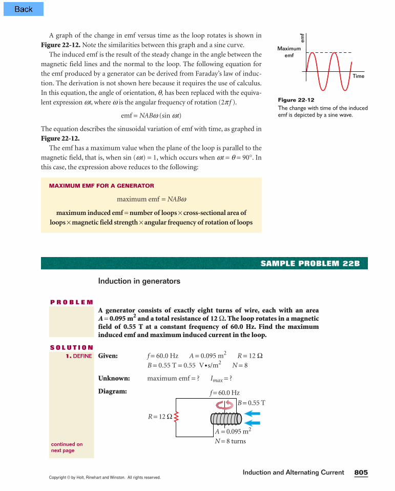
A graph of the change in emf versus time as the loop rotates is shown in
Figure 22-12. Note the similarities between this graph and a sine curve.
The induced emf is the result of the steady change in the angle between the
magnetic field lines and the normal to the loop. The following equation for
the emf produced by a generator can be derived from Faraday’s law of induc-
tion. The derivation is not shown here because it requires the use of calculus.
In this equation, the angle of orientation, q, has been replaced with the equiva-
lent expression wt, where w is the angular frequency of rotation (2p f ).
emf = NABw (sin wt)
The equation describes the sinusoidal variation of emf with time, as graphed in
Figure 22-12.The emf has a maximum value when the plane of the loop is parallel to the
magnetic field, that is, when sin (wt) = 1, which occurs when wt = q = 90°. In
this case, the expression above reduces to the following:
MAXIMUM EMF FOR A GENERATOR
maximum emf = NABw
maximum induced emf = number of loops × cross-sectional area ofloops × magnetic field strength × angular frequency of rotation of loops
Copyright © by Holt, Rinehart and Winston. All rights reserved.Chapter 22806
2. PLAN
3. CALCULATE
4. EVALUATE
1. In a model generator, a 510-turn rectangular coil 0.082 m by 0.25 m
rotates with an angular frequency of 12.8 rad/s in a uniform magnetic
field of 0.65 T. What is the maximum emf induced in the coil?
2. A circular coil with a radius of R = 0.22 m and 17 turns is rotated in a
uniform magnetic field of 1.7 T. The coil rotates at a constant frequency
of 2.0 Hz. Determine the maximum value of the emf induced in the coil.
3. A square coil with an area of 0.045 m2 consists of 120 turns of wire. The
coil rotates about a vertical axis at 157 rad/s. The horizontal component
of Earth’s magnetic field at the location of the loop is 2.0 × 10⁻⁵ T. Calcu-
late the maximum emf induced in the coil.
4. A maximum emf of 90.4 V is induced in a generator coil rotating with a
frequency of 65 Hz. If the coil has an area of 230 cm2 and rotates in a
magnetic field of 1.2 T, how many turns are in the coil?
Induction in generators
PRACTICE 22B
Choose an equation(s) or situation: Use the maximum emf equation for a
generator. Use the definition of angular frequency to convert f to w. The
maximum current can be obtained from the definition for resistance.
maximum emf = NABw w = 2pf
Imax = maxim
R
um emf
Rearrange the equation(s) to isolate the unknown(s): Substitute the angu-
lar frequency expression into the maximum emf equation.
maximum emf = NAB(2pf )
Substitute the values into the equation(s) and solve:
maximum emf = (8)(0.095 m2)(0.55 T)(2p)(60.0 Hz)
Imax = 1.6
1
×2
1
Ω02 V = 13 A
By expressing the units used in the calculation in terms of equivalent units
(1 T = 1 (V•s/m2) and 1 Hz = 1/s), you can see which terms cancel. In this
case, m2 and s cancel to leave the answer for emf in units of volts.
Imax = 13 A
maximum emf = 1.6 × 10² V CALCULATOR SOLUTION
Because the minimum number of sig-nificant figures for the data is two,the calculator answer, 157.5822875,should be rounded to two digits.
Copyright © by Holt, Rinehart and Winston. All rights reserved.
Although the light intensity from a60 W incandescent light bulbappears to be constant, the currentin the bulb fluctuates 60 times eachsecond between −0.7 1 A and 0.7 1 A.The light appears to be steadybecause the fluctuations are toorapid for our eyes to perceive.
807Induction and Alternating Current
Alternating current changes direction at a constant frequency
The output emf of a typical generator has a sinusoidal pattern, as you can see
in the graph in Figure 22-12 on page 805. Note that the emf alternates from
positive to negative. As a result, the output current from the generator
changes its direction at regular intervals. This variety of current is called alter-nating current, or, more commonly, ac.
The rate at which the coil in an ac generator rotates determines the maxi-
mum generated emf. The frequency of the alternating current can differ from
country to country. In the United States, Canada, and Central America, the
frequency of rotation for commercial generators is 60 Hz. This means that the
emf undergoes one full cycle of changing direction 60 times each second. In
the United Kingdom, Europe, and most of Asia and Africa, 50 Hz is used.
(Recall that w = 2p f , where f is the frequency in Hz.)
Resistors can be used in either alternating- or direct-current applications.
A resistor resists the motion of charges regardless of whether they move in
one continuous direction or shift direction periodically. Thus, if the definition
for resistance holds for circuit elements in a dc circuit, it will also hold for the
same circuit elements with alternating currents and emfs.
Effective current and potential difference are measured in ac circuits
An ac circuit consists of combinations of circuit elements and an ac generator
or an ac power supply, which provides the alternating current. As shown
earlier, the emf produced by a typical ac generator is sinusoidal and varies
with time. The induced emf equals the instantaneous ac potential difference,
which is written as ∆v. The quantity for the maximum emf can be written as
the maximum potential difference ∆Vmax, and the emf produced by a genera-
tor can be expressed as follows:
∆v = ∆Vmax(sin wt)
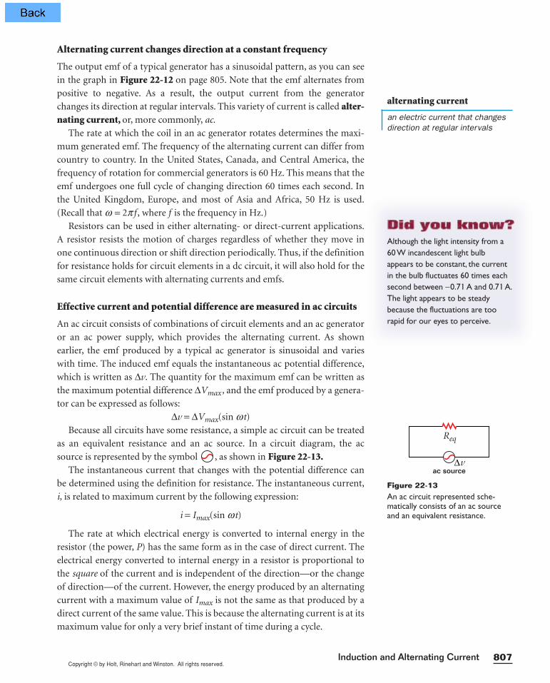
Because all circuits have some resistance, a simple ac circuit can be treated
as an equivalent resistance and an ac source. In a circuit diagram, the ac
source is represented by the symbol , as shown in Figure 22-13.The instantaneous current that changes with the potential difference can
be determined using the definition for resistance. The instantaneous current,
i, is related to maximum current by the following expression:
i = Imax(sin wt)
The rate at which electrical energy is converted to internal energy in the
resistor (the power, P) has the same form as in the case of direct current. The
electrical energy converted to internal energy in a resistor is proportional to
the square of the current and is independent of the direction—or the change
of direction—of the current. However, the energy produced by an alternating
current with a maximum value of Imax is not the same as that produced by a
direct current of the same value. This is because the alternating current is at its
maximum value for only a very brief instant of time during a cycle.
v
Req
ac source∆
Figure 22-13An ac circuit represented sche-matically consists of an ac sourceand an equivalent resistance.
alternating current
an electric current that changesdirection at regular intervals
Copyright © by Holt, Rinehart and Winston. All rights reserved.Chapter 22808
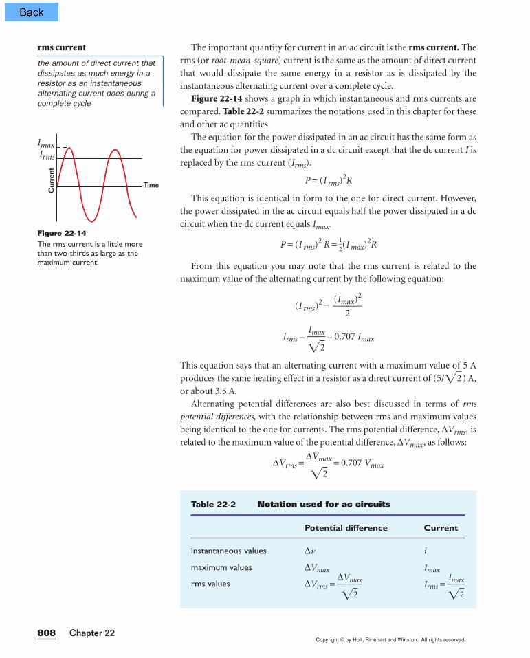
The important quantity for current in an ac circuit is the rms current. The
rms (or root-mean-square) current is the same as the amount of direct current
that would dissipate the same energy in a resistor as is dissipated by the
instantaneous alternating current over a complete cycle.
Figure 22-14 shows a graph in which instantaneous and rms currents are
compared. Table 22-2 summarizes the notations used in this chapter for these
and other ac quantities.
The equation for the power dissipated in an ac circuit has the same form as
the equation for power dissipated in a dc circuit except that the dc current I is
replaced by the rms current (Irms).
P = (I rms)2R
This equation is identical in form to the one for direct current. However,
the power dissipated in the ac circuit equals half the power dissipated in a dc
circuit when the dc current equals Imax.
P = (I rms)2 R = 1
2(I max)2R
From this equation you may note that the rms current is related to the
maximum value of the alternating current by the following equation:
(I rms)2 =
(Im
2ax)2
Irms = Ima
2x = 0.707 Imax
This equation says that an alternating current with a maximum value of 5 A
produces the same heating effect in a resistor as a direct current of (5/2 ) A,
or about 3.5 A.
Alternating potential differences are also best discussed in terms of rms
potential differences, with the relationship between rms and maximum values
being identical to the one for currents. The rms potential difference, ∆Vrms, is
related to the maximum value of the potential difference, ∆Vmax, as follows:
∆Vrms = ∆
Vm
2ax = 0.707 Vmax
ImaxIrms
Cur
rent
Time
Figure 22-14The rms current is a little morethan two-thirds as large as the maximum current.
rms current
the amount of direct current thatdissipates as much energy in aresistor as an instantaneousalternating current does during acomplete cycle
Table 22-2 Notation used for ac circuits
Potential difference Current
instantaneous values ∆v i
maximum values ∆Vmax Imax
rms values ∆Vrms = ∆
Vm
2ax Irms =
Imax2
Copyright © by Holt, Rinehart and Winston. All rights reserved.809Induction and Alternating Current
The ac potential difference of 120 V measured from an electric outlet is
actually an rms potential difference of 120 V. A quick calculation shows that
such an ac potential difference has a maximum value of about 170 V.
A resistor limits the current in an ac circuit just as it does in a dc circuit. If
the definition of resistance is valid for an ac circuit, the rms potential differ-
ence across a resistor equals the rms current multiplied by the resistance.
Thus, all maximum and rms values can be calculated if only one current or
emf value and the circuit resistance are known.
Because ac ammeters and voltmeters measure rms values, all values of
alternating current and alternating potential difference in this chapter will be
given as rms values unless otherwise noted. The equations for ac circuits have
the same form as those for dc circuits when rms values are used.
SAMPLE PROBLEM 22C
rms currents and potential differences
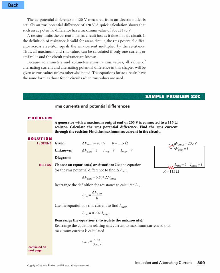
P R O B L E MA generator with a maximum output emf of 205 V is connected to a 115 Ωresistor. Calculate the rms potential difference. Find the rms currentthrough the resistor. Find the maximum ac current in the circuit.
S O L U T I O NGiven: ∆Vmax = 205 V R = 115 Ω
Unknown: ∆Vrms = ? Irms = ? Imax = ?
Diagram:
Choose an equation(s) or situation: Use the equation
for the rms potential difference to find ∆Vrms.
∆Vrms = 0.707 ∆Vmax
Rearrange the definition for resistance to calculate Irms.
Irms = ∆V
Rrms
Use the equation for rms current to find Imax.
Irms = 0.707 Imax
Rearrange the equation(s) to isolate the unknown(s):Rearrange the equation relating rms current to maximum current so that
maximum current is calculated.
Imax = 0
I
.r
7m
0s
7
1. DEFINE
2. PLAN
continued onnext page
R = 115 Ω
Vmax = 205 V
Vrms = ?
Irms = ? Imax = ?
∆∆
Copyright © by Holt, Rinehart and Winston. All rights reserved.Chapter 22810
Substitute the values into the equation(s) and solve:
∆Vrms = (0.707)(205 V) = 145 V
Irms = 1
1
1
4
5
5
ΩV
= 1.26 A
Imax = 1
0
.
.
2
7
6
07
A = 1.78 A
The rms values for potential difference and current are a little more than
two-thirds the maximum values, as expected.
∆Vrms = 145 V
Irms = 1.26 A
Imax = 1.78 A
4. EVALUATE
3. CALCULATE
CALCULATOR SOLUTION
Because the minimum number of significant figures for the data is three,the calculator solution for the rmspotential difference, 144.935, shouldbe rounded to three digits.
1. What is the rms current in a light bulb that has a resistance of 25 Ω and
an rms potential difference of 120 V? What are the maximum values for
current and potential difference?
2. The current in an ac circuit is measured with an ammeter. The meter
gives a reading of 5.5 A. Calculate the maximum ac current.
3. A toaster is plugged into a source of alternating potential difference with
an rms value of 110 V. The heating element is designed to convey a cur-
rent with a maximum value of 10.5 A. Find the following:
a. the rms current in the heating element
b. the resistance of the heating element
4. An audio amplifier provides an alternating rms potential difference of
15.0 V. A loudspeaker connected to the amplifier has a resistance of
10.4 Ω. What is the rms current in the speaker? What are the maximum
values of the current and the potential difference?
5. An ac generator has a maximum potential difference output of 155 V.
a. Find the rms potential difference output.
b. Find the rms current in the circuit when the generator is connected to
a 53 Ω resistor.
6. The largest potential difference that can be placed across a certain capaci-
tor at any instant is 451 V. What is the largest rms potential difference
that can be placed across the capacitor without damaging it?
rms currents and potential differences
PRACTICE 22C
Copyright © by Holt, Rinehart and Winston. All rights reserved.811Induction and Alternating Current
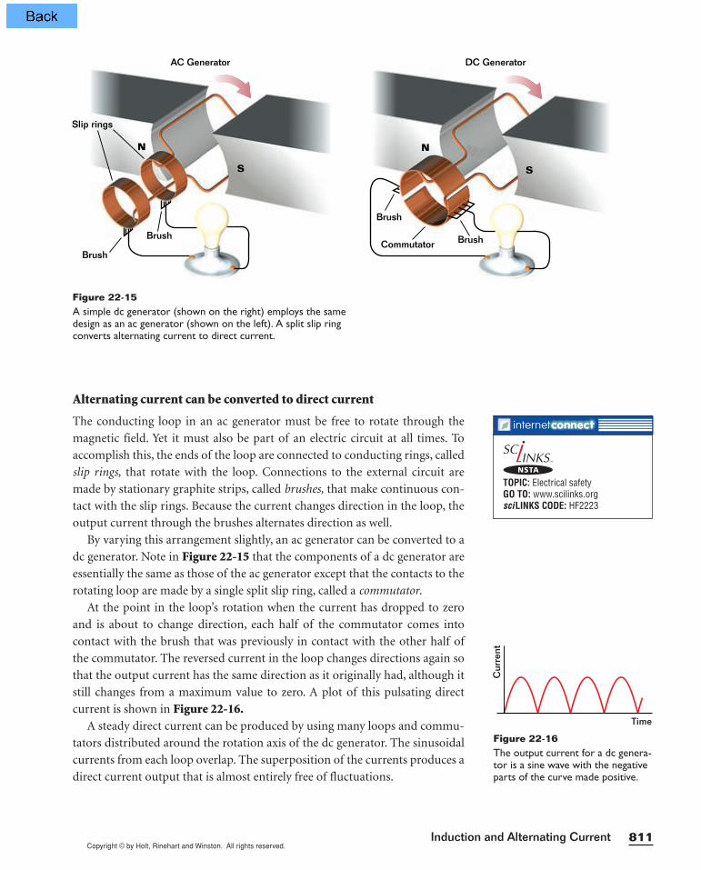
Alternating current can be converted to direct current
The conducting loop in an ac generator must be free to rotate through the
magnetic field. Yet it must also be part of an electric circuit at all times. To
accomplish this, the ends of the loop are connected to conducting rings, called
slip rings, that rotate with the loop. Connections to the external circuit are
made by stationary graphite strips, called brushes, that make continuous con-
tact with the slip rings. Because the current changes direction in the loop, the
output current through the brushes alternates direction as well.
By varying this arrangement slightly, an ac generator can be converted to a
dc generator. Note in Figure 22-15 that the components of a dc generator are
essentially the same as those of the ac generator except that the contacts to the
rotating loop are made by a single split slip ring, called a commutator.
At the point in the loop’s rotation when the current has dropped to zero
and is about to change direction, each half of the commutator comes into
contact with the brush that was previously in contact with the other half of
the commutator. The reversed current in the loop changes directions again so
that the output current has the same direction as it originally had, although it
still changes from a maximum value to zero. A plot of this pulsating direct
current is shown in Figure 22-16.A steady direct current can be produced by using many loops and commu-
tators distributed around the rotation axis of the dc generator. The sinusoidal
currents from each loop overlap. The superposition of the currents produces a
direct current output that is almost entirely free of fluctuations.
AC Generator DC Generator
Slip rings
Brush
Brush
N
S
N
S
Brush
BrushCommutator
Figure 22-15A simple dc generator (shown on the right) employs the samedesign as an ac generator (shown on the left). A split slip ringconverts alternating current to direct current.
Time
Cur
rent
Figure 22-16The output current for a dc genera-tor is a sine wave with the negativeparts of the curve made positive.
TOPIC: Electrical safetyGO TO: www.scilinks.orgsciLINKS CODE: HF2223
NSTA

Copyright © by Holt, Rinehart and Winston. All rights reserved.Chapter 22812
MOTORS
Motors are devices that convert electrical energy to mechanical energy.
Instead of a current being generated by a rotating loop in a magnetic field, a
current is supplied to the loop by an emf source and the magnetic force on the
current loop causes it to rotate (see Figure 22-17).
A motor is almost identical in construction to a dc generator. The coil of
wire is mounted on a rotating shaft and is positioned between the poles of a
magnet. Brushes make contact with a commutator, which alternates the cur-
rent in the coil. This alternation of the current causes the magnetic field pro-
duced by the current to regularly reverse and thus always be repelled by the
fixed magnetic field. Thus, the coil and the shaft are kept in continuous rota-
tional motion.
A motor can perform useful mechanical work when a shaft connected to
its rotating coil is attached to some external device. As the coil in the motor
rotates, however, the changing normal component of the magnetic field
through it induces an emf that acts to reduce the current in the coil. If this
were not the case, Lenz’s law would be violated. This induced emf is called
the back emf.The back emf increases in magnitude as the magnetic field changes at a
higher rate. In other words, the faster the coil rotates, the greater the back
emf becomes. The potential difference available to supply current to the
motor equals the difference between the applied potential difference and the
back emf. Consequently, the current in the coil is also reduced because of
the presence of back emf. The faster the motor turns, the smaller the net
potential difference across the motor, and the smaller the net current in the
coil, becomes.
DC Motor
Brush
Brush
CommutatorN
S
emf
+
Figure 22-17In a motor, the current in the coil interactswith the magnetic field, causing the coil and theshaft on which the coil is mounted to turn.
back emf
the emf induced in a motor’s coilthat tends to reduce the currentpowering the motor
Copyright © by Holt, Rinehart and Winston. All rights reserved.813Induction and Alternating Current
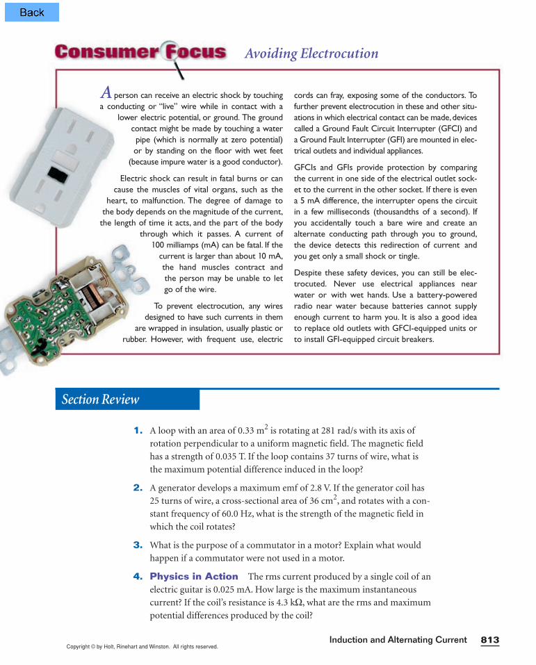
A person can receive an electric shock by touchinga conducting or “live” wire while in contact with a
lower electric potential, or ground. The groundcontact might be made by touching a waterpipe (which is normally at zero potential)or by standing on the floor with wet feet
(because impure water is a good conductor).
Electric shock can result in fatal burns or cancause the muscles of vital organs, such as the
heart, to malfunction. The degree of damage tothe body depends on the magnitude of the current,
the length of time it acts, and the part of the bodythrough which it passes. A current of
100 milliamps (mA) can be fatal. If thecurrent is larger than about 10 mA,the hand muscles contract andthe person may be unable to let go of the wire.
To prevent electrocution, any wiresdesigned to have such currents in them
are wrapped in insulation, usually plastic orrubber. However, with frequent use, electric
cords can fray, exposing some of the conductors. Tofurther prevent electrocution in these and other situ-ations in which electrical contact can be made,devicescalled a Ground Fault Circuit Interrupter (GFCI) anda Ground Fault Interrupter (GFI) are mounted in elec-trical outlets and individual appliances.
GFCIs and GFIs provide protection by comparingthe current in one side of the electrical outlet sock-et to the current in the other socket. If there is evena 5 mA difference, the interrupter opens the circuitin a few milliseconds (thousandths of a second). Ifyou accidentally touch a bare wire and create analternate conducting path through you to ground,the device detects this redirection of current andyou get only a small shock or tingle.
Despite these safety devices, you can still be elec-trocuted. Never use electrical appliances nearwater or with wet hands. Use a battery-poweredradio near water because batteries cannot supplyenough current to harm you. It is also a good ideato replace old outlets with GFCI-equipped units orto install GFI-equipped circuit breakers.
Avoiding Electrocution
Section Review
1. A loop with an area of 0.33 m2 is rotating at 281 rad/s with its axis of
rotation perpendicular to a uniform magnetic field. The magnetic field
has a strength of 0.035 T. If the loop contains 37 turns of wire, what is
the maximum potential difference induced in the loop?
2. A generator develops a maximum emf of 2.8 V. If the generator coil has
25 turns of wire, a cross-sectional area of 36 cm2, and rotates with a con-
stant frequency of 60.0 Hz, what is the strength of the magnetic field in
which the coil rotates?
3. What is the purpose of a commutator in a motor? Explain what would
happen if a commutator were not used in a motor.
4. Physics in Action The rms current produced by a single coil of an
electric guitar is 0.025 mA. How large is the maximum instantaneous
current? If the coil’s resistance is 4.3 kΩ, what are the rms and maximum
potential differences produced by the coil?

Copyright © by Holt, Rinehart and Winston. All rights reserved.Chapter 22814
22-3Inductance
MUTUAL INDUCTANCE
The basic principle of electromagnetic induction was first demonstrated by
Michael Faraday. His experimental apparatus, which resembled the arrange-
ment shown in Figure 22-18, used a coil connected to a switch and a battery
instead of a magnet to produce a magnetic field. This coil is called the primary
coil, and its circuit is called the primary circuit. The magnetic field is strength-
ened by the magnetic properties of the iron ring around which the primary
coil is wrapped.
A second coil is wrapped around another part of the iron ring and is con-
nected to a galvanometer. An emf is induced in this coil, called the secondary
coil, when the magnetic field of the primary coil is changed. When the switch in
the primary circuit is closed, the galvanometer in the secondary circuit deflects
in one direction and then returns to zero. When the switch is opened, the gal-
vanometer deflects in the opposite direction and again returns to zero. When
there is a steady current in the primary circuit, the galvanometer reads zero.
The magnitude of this emf is predicted by Faraday’s law of induction.
However, Faraday’s law can be rewritten so that the induced emf is propor-
tional to the changing current in the primary coil. This can be done because of
the direct proportionality between the magnetic field produced by a current
in a coil, or solenoid, and the current itself. The form of Faraday’s law in terms
of changing primary current is as follows:
emf = −N∆[AB
∆(c
t
os q)] = −M
∆∆
I
t
The constant, M, is called the mutual inductance of the two-coil system. The
mutual inductance depends on the geometrical properties of the coils and
22-3 SECTION OBJECTIVES
• Describe how mutualinduction occurs in circuits.
• Calculate the potentialdifference from a step-up orstep-down transformer.
• Describe how self-inductionoccurs in an electric circuit.
Ironring
Primarycoil
Secondarycoil
Galvanometer
+
100
200
300
400
500
600
700
800
900
100
200
300
400
500
600
700
800
900
1000
0 +
Figure 22-18Faraday’s electromagnetic-inductionexperiment used a changing currentin one circuit to induce a current inanother circuit.
mutual inductance
a measure of the ability of one cir-cuit carrying a changing current toinduce an emf in a nearby circuit
Copyright © by Holt, Rinehart and Winston. All rights reserved.815Induction and Alternating Current
their orientation to each other. Because these properties are kept constant, it
follows that a changing current in the secondary coil can also induce an emf in
the primary circuit. The equation holds as long as the coils remain unchanged
with respect to each other, so that the mutual inductance is constant.
By changing the number of turns of wire in the secondary coil, the induced
emf in the secondary circuit can be changed. This arrangement is the basis of
an extremely useful electrical device: the transformer.
TRANSFORMERS
It is often desirable or necessary to change a small ac potential difference to a
larger one or to change a large potential difference to a smaller one. The
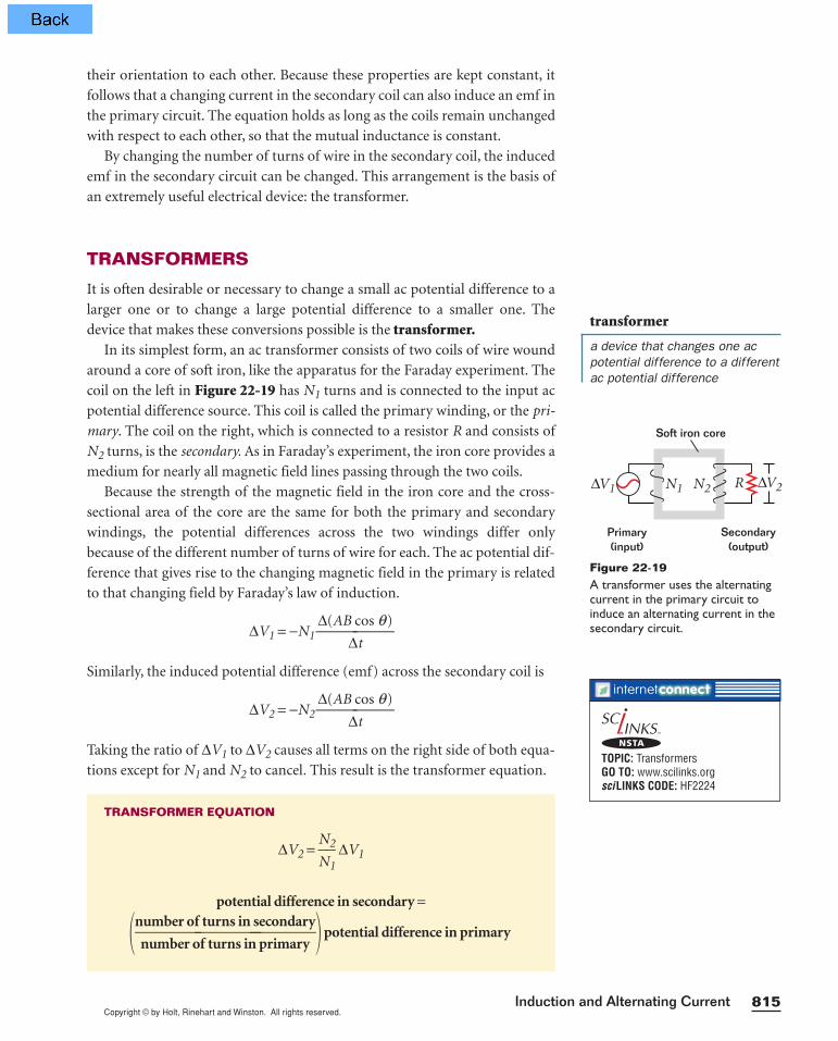
device that makes these conversions possible is the transformer.In its simplest form, an ac transformer consists of two coils of wire wound
around a core of soft iron, like the apparatus for the Faraday experiment. The
coil on the left in Figure 22-19 has N1 turns and is connected to the input ac
potential difference source. This coil is called the primary winding, or the pri-
mary. The coil on the right, which is connected to a resistor R and consists of
N2 turns, is the secondary. As in Faraday’s experiment, the iron core provides a
medium for nearly all magnetic field lines passing through the two coils.
Because the strength of the magnetic field in the iron core and the cross-
sectional area of the core are the same for both the primary and secondary
windings, the potential differences across the two windings differ only
because of the different number of turns of wire for each. The ac potential dif-
ference that gives rise to the changing magnetic field in the primary is related
to that changing field by Faraday’s law of induction.
∆V1 = −N1 ∆(AB
∆c
t
os q)
Similarly, the induced potential difference (emf) across the secondary coil is
∆V2 = −N2 ∆(AB
∆c
t
os q)
Taking the ratio of ∆V1 to ∆V2 causes all terms on the right side of both equa-
tions except for N1 and N2 to cancel. This result is the transformer equation.
TRANSFORMER EQUATION
∆V2 = N
N2
1 ∆V1
potential difference in secondary =
number of turns in secondarynumber of turns in primary
potential difference in primary
Soft iron core
Primary(input)
∆V1 ∆V2N1 N2 R
Secondary(output)
Figure 22-19A transformer uses the alternatingcurrent in the primary circuit toinduce an alternating current in thesecondary circuit.
transformer
a device that changes one acpotential difference to a differentac potential difference
TOPIC: TransformersGO TO: www.scilinks.orgsciLINKS CODE: HF2224
NSTA
Copyright © by Holt, Rinehart and Winston. All rights reserved.Chapter 22816
Another way to express this equation is to equate the ratio of the potential dif-
ferences to the ratio of the number of turns.
∆∆
V
V2
1 =
N
N2
1
When N2 is greater than N1, the secondary potential difference is greater
than that of the primary, and the transformer is called a step-up transformer.
When N2 is less than N1, the secondary potential difference is less than that
of the primary, and the transformer is called a step-down transformer.
It may seem that a transformer provides something for nothing. For
example, a step-up transformer can change an input potential difference
from 10 V to 100 V. However, the power input at the primary must equal the
power output at the secondary. An increase in potential difference at the sec-
ondary means that there must be a proportional decrease in current. If the
potential difference at the secondary is 10 times that at the primary, then the
current at the secondary is reduced by a factor of 10.
Real transformers are not perfectly efficient
The transformer equation assumes that there are no
power losses between the transformer’s primary and its
secondary. Real transformers typically have efficiencies
ranging from 90 percent to 99 percent. Power losses
occur because of the small currents induced by changing
magnetic fields in the iron core of the transformer and
because of resistance in the wires of the windings.
When electric power is transmitted over large dis-
tances, it is economical to use a high potential difference
and a low current. This is because the power lost to resis-
tive heating in the transmission lines varies as I2R. By
reducing the current by a factor of 10, the power loss is
reduced by a factor of 100. In practice, potential differ-
ence is stepped up to around 230 000 V at the generating
station, then stepped down to 20 000 V at a regional dis-
tribution station, and finally stepped down to 120 V at the
customer’s utility pole. The high potential difference in
long-distance transmission lines makes them especially
dangerous when they are knocked down by high winds.
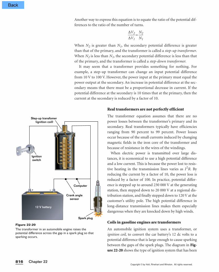
Coils in gasoline engines are transformers
An automobile ignition system uses a transformer, or
ignition coil, to convert the car battery’s 12 dc volts to a
potential difference that is large enough to cause sparking
between the gaps of the spark plugs. The diagram in Fig-ure 22-20 shows the type of ignition system that has been
–+
12 V battery
Step-up transfomer (ignition coil)
Spark plug
Ignitionswitch
Computer
Crank anglesensor
Figure 22-20The transformer in an automobile engine raises the potential difference across the gap in a spark plug so thatsparking occurs.
Copyright © by Holt, Rinehart and Winston. All rights reserved.817Induction and Alternating Current
used in automobiles since 1990. In this arrangement, each cylinder has its own
transformer, and a photoelectric detector called a crank angle sensor determines
from the crankshaft’s position which cylinder’s contents are at maximum com-
pression. Upon receiving this signal, the computer closes the primary circuit to
the cylinder’s coil, causing the current in the primary to rapidly increase and
the magnetic field in the transformer to change. This, in turn, induces a poten-
tial difference of about 20 000 V across the secondary.
SAMPLE PROBLEM 22D
Transformers
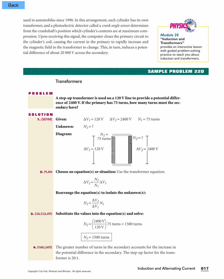
P R O B L E MA step-up transformer is used on a 120 V line to provide a potential differ-ence of 2400 V. If the primary has 75 turns, how many turns must the sec-ondary have?
S O L U T I O NGiven: ∆V1 = 120 V ∆V2 = 2400 V N1 = 75 turns
Unknown: N2 = ?
Diagram:
Choose an equation(s) or situation: Use the transformer equation.
∆V2 = N
N2
1 ∆V1
Rearrange the equation(s) to isolate the unknown(s):
N2 = ∆∆
V
V2
1 N1
Substitute the values into the equation(s) and solve:
N2 = 2142000V
V 75 turns = 1500 turns
The greater number of turns in the secondary accounts for the increase in
the potential difference in the secondary. The step-up factor for the trans-
former is 20:1.
N2 = 1500 turns
∆V2 = 2400 V∆V1 = 120 V
N1 =75 turns N2 = ?
1. DEFINE
2. PLAN
4. EVALUATE
3. CALCULATE
INTERACTIV
E•
T U T O RPHYSICSPHYSICS
Module 20“Induction and Transformers”provides an interactive lessonwith guided problem-solvingpractice to teach you aboutinduction and transformers.
Copyright © by Holt, Rinehart and Winston. All rights reserved.
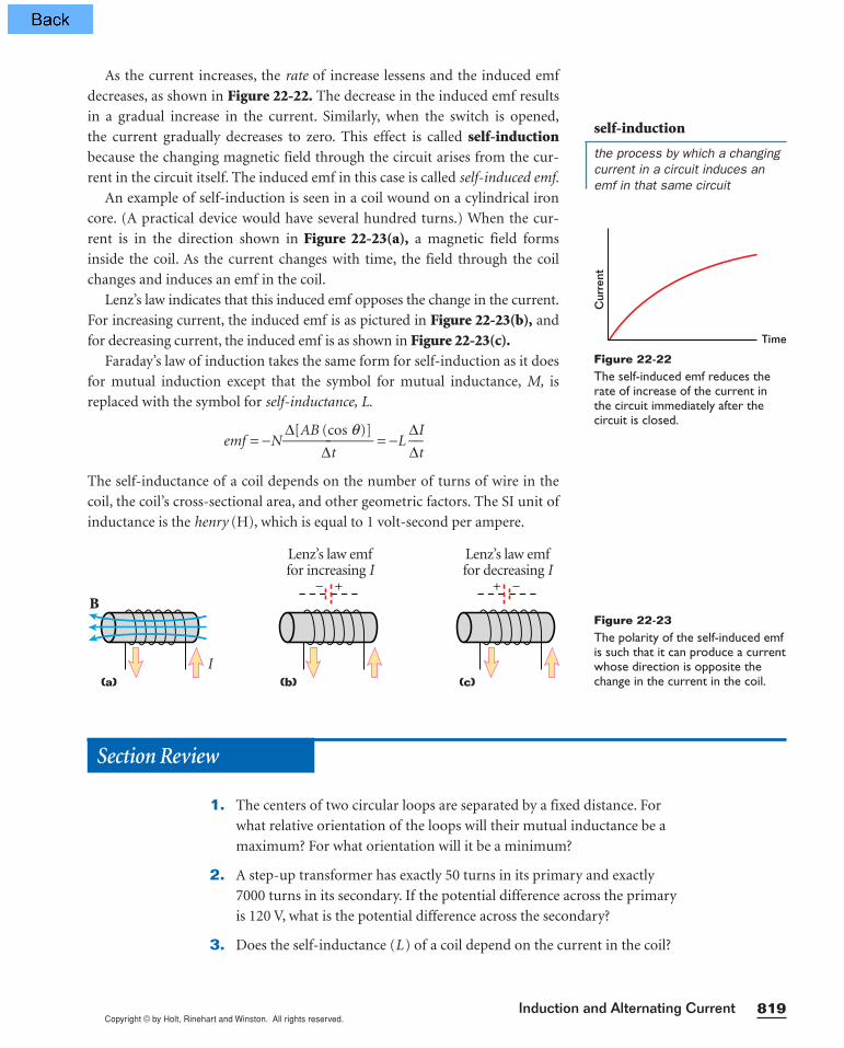
SELF-INDUCTION
Consider a circuit consisting of a switch, a resistor, and a source of emf, as
shown in Figure 22-21. When the switch is closed, the current does not imme-
diately change from zero to its maximum value, Imax. Instead, the current
increases with time, and the magnetic field through the loop due to this cur-
rent also increases. The increasing field induces an emf in the circuit to oppose
the change in magnetic field, according to Lenz’s law, and so the polarity of the
induced emf must oppose the direction of the original current. The induced
emf is in the direction indicated by the dashed battery. The net potential differ-
ence across the resistor is the emf of the battery minus the induced emf.
Chapter 22818
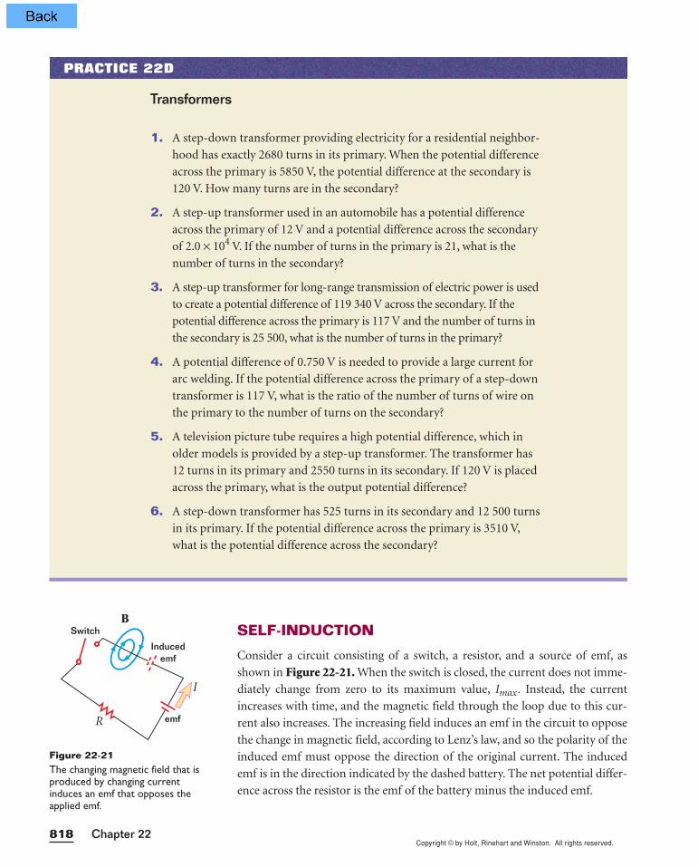
1. A step-down transformer providing electricity for a residential neighbor-
hood has exactly 2680 turns in its primary. When the potential difference
across the primary is 5850 V, the potential difference at the secondary is
120 V. How many turns are in the secondary?
2. A step-up transformer used in an automobile has a potential difference
across the primary of 12 V and a potential difference across the secondary
of 2.0 × 10⁴ V. If the number of turns in the primary is 21, what is the
number of turns in the secondary?
3. A step-up transformer for long-range transmission of electric power is used
to create a potential difference of 119 340 V across the secondary. If the
potential difference across the primary is 117 V and the number of turns in
the secondary is 25 500, what is the number of turns in the primary?
4. A potential difference of 0.750 V is needed to provide a large current for
arc welding. If the potential difference across the primary of a step-down
transformer is 117 V, what is the ratio of the number of turns of wire on
the primary to the number of turns on the secondary?
5. A television picture tube requires a high potential difference, which in
older models is provided by a step-up transformer. The transformer has
12 turns in its primary and 2550 turns in its secondary. If 120 V is placed
across the primary, what is the output potential difference?
6. A step-down transformer has 525 turns in its secondary and 12 500 turns
in its primary. If the potential difference across the primary is 3510 V,
what is the potential difference across the secondary?
Transformers
PRACTICE 22D
BSwitch
Inducedemf
emf
I
R
Figure 22-21The changing magnetic field that isproduced by changing currentinduces an emf that opposes theapplied emf.
Copyright © by Holt, Rinehart and Winston. All rights reserved.819Induction and Alternating Current
As the current increases, the rate of increase lessens and the induced emf
decreases, as shown in Figure 22-22. The decrease in the induced emf results
in a gradual increase in the current. Similarly, when the switch is opened,
the current gradually decreases to zero. This effect is called self-inductionbecause the changing magnetic field through the circuit arises from the cur-
rent in the circuit itself. The induced emf in this case is called self-induced emf.
An example of self-induction is seen in a coil wound on a cylindrical iron
core. (A practical device would have several hundred turns.) When the cur-
rent is in the direction shown in Figure 22-23(a), a magnetic field forms
inside the coil. As the current changes with time, the field through the coil
changes and induces an emf in the coil.
Lenz’s law indicates that this induced emf opposes the change in the current.
For increasing current, the induced emf is as pictured in Figure 22-23(b), and
for decreasing current, the induced emf is as shown in Figure 22-23(c).Faraday’s law of induction takes the same form for self-induction as it does
for mutual induction except that the symbol for mutual inductance, M, is
replaced with the symbol for self-inductance, L.
emf = −N∆[AB
∆(c
t
os q)] = −L
∆∆
I
t
The self-inductance of a coil depends on the number of turns of wire in the
coil, the coil’s cross-sectional area, and other geometric factors. The SI unit of
inductance is the henry (H), which is equal to 1 volt-second per ampere.
Cur
rent
Time
Figure 22-22The self-induced emf reduces therate of increase of the current inthe circuit immediately after the circuit is closed.
I
B
Lenz’s law emffor increasing I
Lenz’s law emffor decreasing I
(a) (b) (c)
+ −− +
Figure 22-23The polarity of the self-induced emfis such that it can produce a currentwhose direction is opposite thechange in the current in the coil.
Section Review
1. The centers of two circular loops are separated by a fixed distance. For
what relative orientation of the loops will their mutual inductance be a
maximum? For what orientation will it be a minimum?
2. A step-up transformer has exactly 50 turns in its primary and exactly
7000 turns in its secondary. If the potential difference across the primary
is 120 V, what is the potential difference across the secondary?
3. Does the self-inductance (L) of a coil depend on the current in the coil?
self-induction
the process by which a changingcurrent in a circuit induces anemf in that same circuit
Copyright © by Holt, Rinehart and Winston. All rights reserved.Chapter 22820
CHAPTER 22Summary
KEY IDEAS
Section 22-1 Induced current• Changing the magnetic field strength near a conductor induces an emf.
• The direction of an induced current in a circuit is such that its magnetic
field opposes the change in the applied magnetic field.
• Induced emf can be calculated using
Faraday’s law of magnetic induction.
Section 22-2 Alternating current, generators, and motors• Generators use induction to convert mechanical energy into electrical energy.
• Alternating current is measured in terms of rms current.
• Motors use an arrangement similar to that of generators to convert electri-
cal energy into mechanical energy.
Section 22-3 Inductance• Mutual inductance involves the induction of a current in one circuit by
means of a changing current in a nearby circuit.
• Transformers change the potential difference of an alternating current.
• Self-induction occurs when the changing current in a circuit induces an
emf in the same circuit.
KEY TERMS
alternating current (p. 807)
back emf (p. 812)
electromagnetic induction(p. 794)
generator (p. 803)
mutual inductance (p. 814)
rms current (p. 808)
self-induction (p. 819)
transformer (p. 815)
emf = −N ∆[AB
∆(c
t
os q)]
Variable symbols
Quantities Units
N number of turns (unitless)
∆Vmax maximum potential difference V volt
∆Vrms rms potential difference V volt
Imax maximum current A ampere
Irms rms current A ampere
M mutual inductance H henry = vo
a
lt
m
•s
p
e
e
c
r
o
e
nd
L self-inductance H henry = vo
a
lt
m
•s
p
e
e
c
r
o
e
nd
Diagram symbols
Induced emf
ac generator/alternating currentemf source
+−
Copyright © by Holt, Rinehart and Winston. All rights reserved.821Induction and Alternating Current
INDUCED CURRENT
Review questions
1. Suppose you have two circuits. One consists of anelectromagnet, a dc emf source, and a variable resis-tor that permits you to control the strength of themagnetic field. In the second circuit, you have a coilof wire and a galvanometer. List three ways that youcan induce a current in the second circuit.
2. Explain how Lenz’s law allows you to determine thedirection of an induced current.
3. What four factors affect the magnitude of the inducedemf in a coil of wire?
4. If you have a fixed magnetic field and a length ofwire, how can you increase the induced emf acrossthe ends of the wire?
Conceptual questions
5. Rapidly inserting the north pole of a bar magnetinto a coil of wire connected to a galvanometercauses the needle of the galvanometer to deflect tothe right. What will happen to the needle if you dothe following?
a. pull the magnet out of the coilb. let the magnet sit at rest in the coilc. thrust the south end of the magnet into the coil
6. Explain how Lenz’s law illustrates the principle ofenergy conservation.
7. Does dropping a bar magnet down a long coppertube induce a current in the tube? If so, how mustthe magnet be oriented with respect to the tube?
8. Two bar magnets are placed side by side so thatthe north pole of one magnet is next to the southpole of the other magnet. If these magnets arethen pushed toward a coil of wire, would youexpect an emf to be induced in the coil? Explainyour answer.
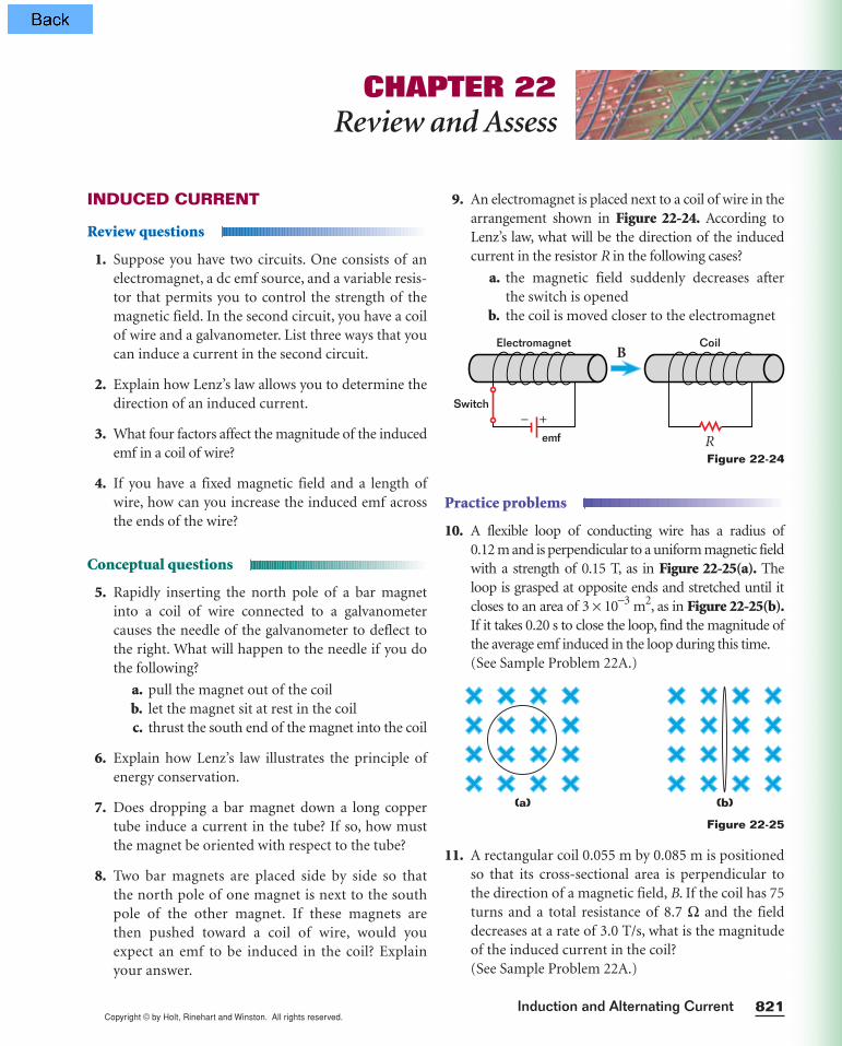
9. An electromagnet is placed next to a coil of wire in thearrangement shown in Figure 22-24. According toLenz’s law, what will be the direction of the inducedcurrent in the resistor R in the following cases?
a. the magnetic field suddenly decreases afterthe switch is opened
b. the coil is moved closer to the electromagnet
Practice problems
10. A flexible loop of conducting wire has a radius of0.12 m and is perpendicular to a uniform magnetic fieldwith a strength of 0.15 T, as in Figure 22-25(a). Theloop is grasped at opposite ends and stretched until itcloses to an area of 3 × 10⁻³ m2, as in Figure 22-25(b).If it takes 0.20 s to close the loop, find the magnitude ofthe average emf induced in the loop during this time.(See Sample Problem 22A.)
11. A rectangular coil 0.055 m by 0.085 m is positionedso that its cross-sectional area is perpendicular tothe direction of a magnetic field, B. If the coil has 75turns and a total resistance of 8.7 Ω and the fielddecreases at a rate of 3.0 T/s, what is the magnitudeof the induced current in the coil?(See Sample Problem 22A.)
Figure 22-25
(a) (b)
Figure 22-24
CHAPTER 22Review and Assess
Electromagnet
emf
Coil
Switch− +
R
B
Copyright © by Holt, Rinehart and Winston. All rights reserved.Chapter 22822
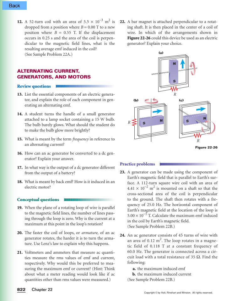
22. A bar magnet is attached perpendicular to a rotat-ing shaft. It is then placed in the center of a coil ofwire. In which of the arrangements shown in Figure 22-26 could this device be used as an electricgenerator? Explain your choice.
Practice problems
23. A generator can be made using the component ofEarth’s magnetic field that is parallel to Earth’s sur-face. A 112-turn square wire coil with an area of4.41 × 10−2 m2 is mounted on a shaft so that thecross-sectional area of the coil is perpendicular to the ground. The shaft then rotates with a fre-quency of 25.0 Hz. The horizontal component ofEarth’s magnetic field at the location of the loop is5.00 × 10−5 T. Calculate the maximum emf inducedin the coil by Earth’s magnetic field.(See Sample Problem 22B.)
24. An ac generator consists of 45 turns of wire withan area of 0.12 m2. The loop rotates in a magne-tic field of 0.118 T at a constant frequency of60.0 Hz. The generator is connected across a cir-cuit load with a total resistance of 35 Ω. Find thefollowing:
a. the maximum induced emfb. the maximum induced current
(See Sample Problem 22B.)
Figure 22-26
(a)
(b) (c)
R
R SN S
N
R
N
S
12. A 52-turn coil with an area of 5.5 × 10⁻³ m2 isdropped from a position where B = 0.00 T to a newposition where B = 0.55 T. If the displacementoccurs in 0.25 s and the area of the coil is perpen-dicular to the magnetic field lines, what is theresulting average emf induced in the coil?(See Sample Problem 22A.)
ALTERNATING CURRENT,GENERATORS, AND MOTORS
Review questions
13. List the essential components of an electric genera-tor, and explain the role of each component in gen-erating an alternating emf.
14. A student turns the handle of a small generatorattached to a lamp socket containing a 15 W bulb.The bulb barely glows. What should the student doto make the bulb glow more brightly?
15. What is meant by the term frequency in reference toan alternating current?
16. How can an ac generator be converted to a dc gen-erator? Explain your answer.
17. In what way is the output of a dc generator differentfrom the output of a battery?
18. What is meant by back emf? How is it induced in anelectric motor?
Conceptual questions
19. When the plane of a rotating loop of wire is parallelto the magnetic field lines, the number of lines pass-ing through the loop is zero. Why is the current at amaximum at this point in the loop’s rotation?
20. The faster the coil of loops, or armature, of an acgenerator rotates, the harder it is to turn the arma-ture. Use Lenz’s law to explain why this happens.
21. Voltmeters and ammeters that measure ac quanti-ties measure the rms values of emf and current,respectively. Why would this be preferred to mea-suring the maximum emf or current? (Hint: Thinkabout what a meter reading would look like if acquantities other than rms values were measured.)
Copyright © by Holt, Rinehart and Winston. All rights reserved.823Induction and Alternating Current
25. The rms potential difference across high-voltagetransmission lines in Great Britain is 220 000 V.What is the maximum potential difference?(See Sample Problem 22C.)
26. The maximum potential difference across certainheavy-duty appliances is 340 V. If the total resistanceof an appliance is 120 Ω, calculate the following:
a. the rms potential differenceb. the rms current
(See Sample Problem 22C.)
27. The maximum current that can pass through a lightbulb filament is 0.909 A when its resistance is 182 Ω.
a. What is the rms current conducted by the fila-ment of the bulb?
b. What is the rms potential difference across thebulb’s filament?
c. How much power does the light bulb use?(See Sample Problem 22C.)
28. A 996 W hair dryer is designed to carry a maximumcurrent of 11.8 A.
a. How large is the rms current in the hair dryer? b. What is the rms potential difference across the
hair dryer?(See Sample Problem 22C.)
INDUCTANCE
Review questions
29. Describe how mutual induction occurs.
30. What is the difference between a step-up transformerand a step-down transformer?
31. Does a step-up transformer increase power? Explainyour answer.
32. Describe how self-induction occurs.
Conceptual questions
33. In many transformers, the wire around one windingis thicker, and therefore has lower resistance, than thewire around the other winding. If the thicker wire iswrapped around the secondary winding, is the devicea step-up or a step-down transformer? Explain.
34. Would a transformer work with pulsating directcurrent? Explain your answer.
Practice problems
35. A transformer is used to convert 120 V to 9.0 V foruse in a portable CD player. If the primary, which isconnected to the outlet, has 640 turns, how manyturns does the secondary have?(See Sample Problem 22D.)
36. A transformer is used to convert 120 V to 6.3 V inorder to power a toy electric train. If there are 210turns in the primary, how many turns should therebe in the secondary?(See Sample Problem 22D.)
MIXED REVIEW PROBLEMS
37. A student attempts to make a simple generator bypassing a single loop of wire between the poles of ahorseshoe magnet with a 2.5 × 10⁻² T field. Thearea of the loop is 7.54 × 10⁻³ m2 and is moved per-pendicular to the magnetic field lines. In whattime interval will the student have to move theloop out of the magnetic field in order to inducean emf of 1.5 V? Is this a practical generator?
38. The same student in item 37 modifies the simplegenerator by wrapping a much longer piece ofwire around a cylinder with about one-fourth thearea of the original loop (1.886 × 10⁻³ m2). Againusing a uniform magnetic field with a strength of2.5 × 10−2 T, the student finds that by removing thecoil perpendicular to the magnetic field lines during0.25 s, an emf of 149 mV can be induced. Howmany turns of wire are wrapped around the coil?
39. A coil of 325 turns and an area of 19.5 × 10⁻⁴ m2 isremoved from a uniform magnetic field at an angleof 45° in 1.25 s. If the induced emf is 15 mV, what isthe magnetic field’s strength?
40. A transformer has 22 turns of wire in its primaryand 88 turns in its secondary.
a. Is this a step-up or step-down transformer?b. If 110 V ac is applied to the primary, what is
the output potential difference?
41. The potential difference in the lines that carry elec-tric power to homes is typically 20.0 kV. What is theratio of the turns in the primary to the turns in thesecondary of the transformer if the output potentialdifference is 117 V?
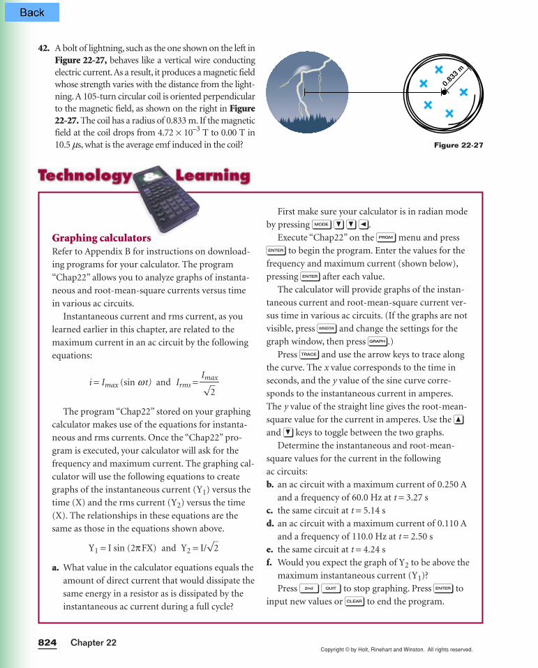
Copyright © by Holt, Rinehart and Winston. All rights reserved.Chapter 22824
42. A bolt of lightning, such as the one shown on the left inFigure 22-27, behaves like a vertical wire conductingelectric current.As a result, it produces a magnetic fieldwhose strength varies with the distance from the light-ning. A 105-turn circular coil is oriented perpendicularto the magnetic field, as shown on the right in Figure22-27. The coil has a radius of 0.833 m. If the magneticfield at the coil drops from 4.72 × 10⁻³ T to 0.00 T in10.5 ms, what is the average emf induced in the coil?
First make sure your calculator is in radian mode
by pressing m ∂ ∂ ¬.
Execute “Chap22” on the p menu and press
e to begin the program. Enter the values for the
frequency and maximum current (shown below),
pressing e after each value.
The calculator will provide graphs of the instan-
taneous current and root-mean-square current ver-
sus time in various ac circuits. (If the graphs are not
visible, press w and change the settings for the
graph window, then press g.)
Press ◊ and use the arrow keys to trace along
the curve. The x value corresponds to the time in
seconds, and the y value of the sine curve corre-
sponds to the instantaneous current in amperes.
The y value of the straight line gives the root-mean-
square value for the current in amperes. Use the ¨
and ∂ keys to toggle between the two graphs.
Determine the instantaneous and root-mean-
square values for the current in the following
ac circuits:
b. an ac circuit with a maximum current of 0.250 A
and a frequency of 60.0 Hz at t = 3.27 s
c. the same circuit at t = 5.14 s
d. an ac circuit with a maximum current of 0.110 A
and a frequency of 110.0 Hz at t = 2.50 s
e. the same circuit at t = 4.24 s
f. Would you expect the graph of Y2 to be above the
maximum instantaneous current (Y1)?
Press @ q to stop graphing. Press e to
input new values or ı to end the program.
Graphing calculatorsRefer to Appendix B for instructions on download-
ing programs for your calculator. The program
“Chap22” allows you to analyze graphs of instanta-
neous and root-mean-square currents versus time
in various ac circuits.
Instantaneous current and rms current, as you
learned earlier in this chapter, are related to the
maximum current in an ac circuit by the following
equations:
i = Imax (sin wt) and Irms =
The program “Chap22” stored on your graphing
calculator makes use of the equations for instanta-
neous and rms currents. Once the “Chap22” pro-
gram is executed, your calculator will ask for the
frequency and maximum current. The graphing cal-
culator will use the following equations to create
graphs of the instantaneous current (Y1) versus the
time (X) and the rms current (Y2) versus the time
(X). The relationships in these equations are the
same as those in the equations shown above.
Y1 = I sin (2πFX) and Y2 = I/√
2
a. What value in the calculator equations equals the
amount of direct current that would dissipate the
same energy in a resistor as is dissipated by the
instantaneous ac current during a full cycle?
Imax√2
0.833
m
Figure 22-27
Copyright © by Holt, Rinehart and Winston. All rights reserved.
43. A generator supplies 5.0 × 10³ kW of power. The out-put potential difference is 4500 V before it is steppedup to 510 kV. The electricity travels 410 mi (6.44 ×10⁵ m) through a transmission line that has a resis-tance per unit length of 4.5 × 10⁻⁴ Ω/m.
a. How much power is lost through transmissionof the electrical energy along the line?
b. How much power would be lost throughtransmission if the generator’s output poten-tial difference were not stepped up? What doesthis answer tell you about the role of largepotential differences in power transmission?
44. The alternating potential difference of a generator isrepresented by the equation emf = (245 V) sin 560t,where emf is in volts and t is in seconds. Use thesevalues to find the frequency of the potential differ-ence and the maximum potential difference outputof the source.
45. A pair of adjacent coils has a mutual inductance of1.06 H. Determine the average emf induced in thesecondary circuit when the current in the primarycircuit changes from 0 A to 9.50 A in a time intervalof 0.0336 s.
Induction and Alternating Current 825
Performance assessment1. Identify the chain of electromagnetic energy trans-
formations involved in making the blades of a ceiling
fan spin. Include the fan’s motor, the transformers
bringing electricity to the house, and the turbines
generating the electricity.
2. Two identical magnets are dropped simultaneously
from the same point. One of them passes through a
coil of wire in a closed circuit. Predict whether the
two magnets will hit the ground at the same time.
Explain your reasoning, then plan an experiment to
test which of the following variables measurably
affect how long each magnet takes to fall: magnetic
strength, coil cross-sectional area, and the number
of loops the coil has. What measurements will you
make? What are the limits of precision in your mea-
surements? If your teacher approves your plan,
obtain the necessary materials and perform the
experiments. Report your results to the class,
describing how you made your measurements, what
you concluded, and what additional questions need
to be investigated.
3. What do adapters do to potential difference, current,
frequency, and power? Examine the input/output
information on several adapters to find out. Do they
contain step-up or step-down transformers? How
does the output current compare to the input? What
happens to the frequency? What percentage of the
energy do they transfer? What are they used for?
Portfolio projects4. Research the debate between the proponents of
alternating current and those who favored direct
current in the 1880–1890s. How were Thomas
Edison and George Westinghouse involved in the
controversy? What advantages and disadvantages
did each side claim? What uses of electricity were
anticipated? What kind of current was finally gener-
ated in the Niagara Falls hydroelectric plant? Had
you been in a position to fund these projects at that
time, which projects would you have funded? Pre-
pare your arguments to re-enact a meeting of busi-
nesspeople in Buffalo in 1887.
5. Research the history of telecommunication. Who
invented the telegraph? Who patented it in Eng-
land? Who patented it in the United States?
Research the contributions of Charles Wheatstone,
Joseph Henry, and Samuel Morse. How did each of
these men deal with issues of fame, wealth, and
credit to other people’s ideas? Write a summary of
your findings, and prepare a class discussion about
the effect patents and copyrights have had on mod-
ern technology.
Alternative Assessment

Chapter 22826
ELECTROMAGNETIC INDUCTIONIn this laboratory, you will use a magnet, a conductor, and a galvanometer to
explore electromagnets and the principle of self-induction.
PREPARATION
1. Read the entire lab, and plan what measurements you will take.
2. In your lab notebook, prepare an observation table with three wide
columns. Label the columns Sketch of setup, Experiment, and Observation.
For each part of the lab, you will sketch the apparatus and label the poles
of the magnet, write a brief description, and record your observations.
PROCEDURE
Induction with a permanent magnet
3. Connect the ends of the smaller coil to the galvanometer. Hold the magnet
still and move the coil quickly over the north pole of the magnet, as shown
in Figure 22-28. Remove the coil quickly. Observe the galvanometer.
4. Repeat, moving the coil more slowly. Observe the galvanometer.
5. Turn the magnet over, and repeat steps 3 and 4, moving the coil over
the south pole of the magnet. Observe the galvanometer.
6. Hold the coil stationary and quickly move the north pole of the magnet
in and out of the coil. Repeat slowly. Turn the magnet, and repeat both
quickly and slowly with the south pole. Observe the galvanometer.
CHAPTER 22Laboratory Exercise
OBJECTIVES
•Use a galvanometer to detect an inducedcurrent.
•Determine the relation-ship between the mag-netic field of a magnetand the current inducedin a conductor.
•Determine what factorsaffect the direction andmagnitude of an inducedcurrent.
MATERIALS LIST galvanometer insulated connecting wires momentary contact switch pair of bar magnets or a large
horseshoe magnet power supply rheostat (10 Ω) or
potentiometer student primary and sec-
ondary coil set with iron core
SAFETY
• Never close a circuit until it has been approved by your teacher. Neverrewire or adjust any element of a closed circuit. Never work with elec-tricity near water; be sure the floor and all work surfaces are dry.
• If the pointer on any kind of meter moves off scale, open the circuitimmediately by opening the switch.
• Do not attempt this exercise with any batteries, electrical devices, ormagnets other than those provided by your teacher for this purpose.
Copyright © by Holt, Rinehart and Winston. All rights reserved.
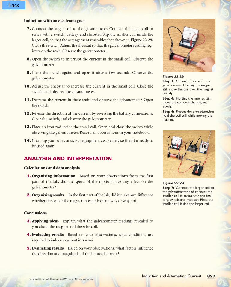
827Induction and Alternating Current
Induction with an electromagnet
7. Connect the larger coil to the galvanometer. Connect the small coil in
series with a switch, battery, and rheostat. Slip the smaller coil inside the
larger coil, so that the arrangement resembles that shown in Figure 22-29.Close the switch. Adjust the rheostat so that the galvanometer reading reg-
isters on the scale. Observe the galvanometer.
8. Open the switch to interrupt the current in the small coil. Observe the
galvanometer.
9. Close the switch again, and open it after a few seconds. Observe the
galvanometer.
10. Adjust the rheostat to increase the current in the small coil. Close the
switch, and observe the galvanometer.
11. Decrease the current in the circuit, and observe the galvanometer. Open
the switch.
12. Reverse the direction of the current by reversing the battery connections.
Close the switch, and observe the galvanometer.
13. Place an iron rod inside the small coil. Open and close the switch while
observing the galvanometer. Record all observations in your notebook.
14. Clean up your work area. Put equipment away safely so that it is ready to
be used again.
ANALYSIS AND INTERPRETATION
Calculations and data analysis
1. Organizing information Based on your observations from the first
part of the lab, did the speed of the motion have any effect on the
galvanometer?
2. Organizing results In the first part of the lab, did it make any difference
whether the coil or the magnet moved? Explain why or why not.
Conclusions
3. Applying ideas Explain what the galvanometer readings revealed to
you about the magnet and the wire coil.
4. Evaluating results Based on your observations, what conditions are
required to induce a current in a wire?
5. Evaluating results Based on your observations, what factors influence
the direction and magnitude of the induced current?
Figure 22-28Step 3: Connect the coil to thegalvanometer. Holding the magnetstill, move the coil over the magnetquickly.Step 4: Holding the magnet still,move the coil over the magnetslowly.Step 6: Repeat the procedure, buthold the coil still while moving themagnet.
Figure 22-29Step 7: Connect the larger coil tothe galvanometer, and connect thesmaller coil in series with the bat-tery, switch, and rheostat. Place thesmaller coil inside the larger coil.
Copyright © by Holt, Rinehart and Winston. All rights reserved.