copyright 2019 hanna lehtonen
TRANSCRIPT

Thesis submitted for examination for the degree of Master ofScience in Technology.
Espoo 29.7.2019Thesis supervisor: Prof. Mikael RinneThesis instructor: M.Sc. (Tech.) Antti Sorsa

Copyright © 2019 Hanna Lehtonen

Aalto University, P.O. BOX 11000, 00076 AALTOwww.aalto.fi
Abstract of master's thesis
AuthorTitle of thesisDegree programme CodeThesis supervisorThesis advisorDate Number of pages Language
Abstract
Keywords

Aalto-yliopisto, PL 11000, 00076 AALTOwww.aalto.fi
Diplomityön tiivistelmä
TekijäTyön nimiKoulutusohjelma KoodiTyön valvojaTyön ohjaajaPäivämäärä Sivumäärä Kieli
Tiivistelmä
Avainsanat

5
AcknowledgementsThis thesis was conducted as a partial fulfillmentGeoengineering. The purpose of the thesis was to develop and test a new method, theAnalytical Hierarchy Process, for grouting material selection in hard rock. The study wascommissioned by Pöyry Finland Oy.
First, I would like to express my gratitude for Pöyry Finland Oy and my managers for theopportunity to write the thesis and funding the project. Thank you for Agnico Eagle FinlandOy for providing me for an interesting case study subject. Furthermore, I am grateful to allthe experts from Pöyry Finland Oy, Agnico Eagle Finland Oy and Bergteamet AB, who gaveme valuable interviews for the work. I would also like to acknowledge my colleagues atPöyry Finland Oy for assisting me in this thesis.
I would also like to thank my supervisor, Professor Mikael Rinne, and my advisor, AnttiSorsa from Pöyry Finland Oy, for the valuable guidance and comments you gave methroughout the thesis project.
Finally, I would like to thank my family and friends, not to mention Tuomas, for providingme for the wonderful memories, great support and wise advises throughout my time atUniversity to the end of this thesis project.
Espoo 29.7.2019
Hanna Lehtonen

6
Table of Contents
AbstractTiivistelmäAcknowledgementsTable of Contents .............................................................................................................. 6Symbols and abbreviations ................................................................................................ 81 Introduction ............................................................................................................... 9
1.1 Background for the study .................................................................................... 91.2 Research objectives ........................................................................................... 101.3 Structure and research methods ......................................................................... 101.4 Scope of the research ......................................................................................... 11
2 Introduction to water management in underground spaces ....................................... 122.1 Reasons for water management ......................................................................... 122.2 Requirements for waterproofing in Finland ....................................................... 122.3 Waterproofing and management in underground spaces .................................... 14
3 Grouting .................................................................................................................. 163.1 Grouting in practice and equipment ................................................................... 163.2 Grouting methods .............................................................................................. 163.3 Grouting materials ............................................................................................. 17
3.3.1 Cementitious grouts ................................................................................... 173.3.2 Chemical grouts ......................................................................................... 20
3.4 Grouting material selection in grouting design ................................................... 254 The analytic hierarchy process ................................................................................. 27
4.1 Overview of the AHP ........................................................................................ 274.2 Defining the hierarchy ....................................................................................... 284.3 Pairwise comparison ......................................................................................... 29
4.3.1 Principles of comparison ............................................................................ 294.3.2 Pairwise comparison matrix ....................................................................... 304.3.3 Numerical scales used in the AHP .............................................................. 31
4.4 Determining the priority vector ......................................................................... 324.5 Consistency of the comparisons ......................................................................... 354.6 Simple example of AHP .................................................................................... 364.7 Criticism of AHP and other MCDM methods .................................................... 39
5 Implementation of AHP into grout selection ............................................................ 415.1 Goal and alternative solutions ............................................................................ 415.2 Determining the criteria ..................................................................................... 41
5.2.1 Execution of grouting work ........................................................................ 425.2.2 Costs and schedule ..................................................................................... 425.2.3 Rock conditions ......................................................................................... 425.2.4 Groundwater properties and environmental impacts ................................... 44
5.3 Hierarchy model for AHP.................................................................................. 455.4 AHP calculations ............................................................................................... 47
6 Case Study: Grout optimization for Kittilä Shaft by AHP ........................................ 486.1 Kittilä mine ....................................................................................................... 48
6.1.1 Expansion project and the new shaft ........................................................... 496.1.2 Site investigations and knowledge of the site .............................................. 506.1.3 Grouting and water management in the shaft .............................................. 51
6.2 Modified hierarchy model ................................................................................. 52

7
6.2.1 Alternatives for grouting material ............................................................... 526.2.2 Hierarchy model for the AHP for Kittilä shaft ............................................ 53
6.3 The priorities of criteria with respect to the goal ................................................ 546.3.1 Priorities according to the client ................................................................. 556.3.2 Priorities according to the contractor .......................................................... 556.3.3 Priorities according to the designer ............................................................. 566.3.4 Final priorities of criteria at level 1 ............................................................. 57
6.4 The priorities of alternatives with respect to the criteria ..................................... 586.4.1 Execution of grouting work ........................................................................ 586.4.2 Costs and schedule ..................................................................................... 616.4.3 Rock conditions ......................................................................................... 636.4.4 Groundwater properties and conditions ...................................................... 70
6.5 Results from the AHP analysis .......................................................................... 727 Discussion and proposals ......................................................................................... 75
7.1 Discussion of the literature review and the AHP hierarchy ................................ 757.2 Analysis of the case study ................................................................................. 767.3 Reliability of the APH method in grout selection ............................................... 797.4 Usability of the AHP in grout selection ............................................................. 807.5 Proposals ........................................................................................................... 81
8 Conclusions ............................................................................................................. 83References ....................................................................................................................... 84List of Appendices .......................................................................................................... 91

8
A [-] Matrix ACI [-] Consistency indexCR [-] Consistency ratioRIn [-] Consistency index of a random-like matrix, i.e. the average
CI of 500 randomly filled matricesX [-] Set of alternativesaij [-] Preference between alternatives xi and xjd95 [µm] In sieve analysis
is comprised of particles with smaller diametern [-] Number of elements in a row/column in an sized matrixwn [-] Priority/weight/preference of an alternativew [-] Vector w/the priority vector w/the eigenvector wwT [-] Transpose of vector w i.e. (wT)ij = (w)jixn [-] Alternative
max [-] Maximum/principal eigenvalue
ABI Acoustic televiewerAC Acrylic groutAHP Analytic hierarchy processBY Finnish Concrete Association (Suomen betoniyhdistys ry)C3A Tricalcium aluminateCa2+ Calcium-ionCE CementCS Colloidal silicaELECTRE Elimination and choice expressing realityGFZ Graphite fault zoneMCDM Multi-criteria decision-makingMFC Micro-cementMML Massive basaltMPL Massive pillow lavaOBI Optical borehole imager/imagingOPC Ordinary Portland cementOTV Optical televiewerPU PolyurethanePVC Polyvinyl chlorideSO4
2- Sulfate-ionTOPSIS Technique for order of preferences by similarity to ideal
solutionUFC Ultrafine cementw/c-ratio Water-to-cement ratio
Micro-cement, see MFC

9
1
1.1 Background for the studyWater management is one of the most significant risks in successfully completing anunderground construction project (Crouthamel, et al., 2005). The inflowing water can causesafety concerns, effect the environment, slow down excavation rates, delay the constructionand create additional costs.
In Finland, the ingress of water is mainly controlled by shotcrete and drainage systems. Rockgrouting is usually conducted systematically with cement in verified leakage areas.Traditionally, Rapid-cement is the most used grouting material in Finland. (Ritola & Vuopio,2002.) Since the requirements of waterproofing have become stricter throughout the recentyears, the utilization of microfine and ultrafine cements as well as chemical groutingmaterials with their smaller particle sizes have increased in grouting. Consequently, today asubstantial amount of different materials and trademarks of grouting materials are availableon the markets. As many decisions in a construction project, the selection of a suitable groutfor the grouting program involves considering many factors. The grout selection can, inreality, become a complicated problem by involving geological, hydrogeological, economic,environmental and empirical factors.
In general, there is no universal way of selecting a grouting material for an undergroundconstruction project. Conventionally, the material is selected by the designer, who considersthe geological and hydrogeological requirements and construction specific needs of theproject to create the requirements for the grouting materials. The contractor then suggests amaterial or materials to be used, which then are approved by the designer and client.Generally, the initial selection of the grouting material by the designer is based on previousknowledge of the material behavior in similar environmental conditions and projects. Thiscreates a situation in which different individuals may have a very different and subjectiveperception of the most optimal grout to be used.
The objective of this study was to create a systematic method for grouting material selectionthat could be used to support design work in any possible underground rock constructionproject. The method tested for this purpose is called the Analytic Hierarchy Process (AHP),which belongs to the group of multi-criteria decision-making (MCDM) tools. Being aMCDM tool, the AHP analysis enables the use of multiple criteria and grouting materialalternatives in one single analysis. As a result, the alternative materials are rankednumerically by their suitability to the underground rock construction project in question.Furthermore, a systematical method used for the material selection in grouting could deliverthe selection of the most suitable material and prevent the use of unsuitable or evenhazardous materials in the environment in question.
The possibilities of the AHP method are widespread. Among others, the method enablescomparing different grouting materials side by side. The views of all involved parties in theproject - the designer, the contractor and the client - can be considered simultaneously andthe reasoning behind the material selection becomes transparent. All relevant factorsaffecting the grouting material selection can be considered all at once, and moreover theanalysis can process both quantitative variables, such as data, and qualitative factors, e.g.experience and practical knowledge.

10
1.2 Research objectivesThe main objective is to determine whether the analytical hierarchy process could be asuitable method to evaluate and select the most suitable grouting material for an undergroundproject. The main research question can be phrased as: Is the AHP a suitable method to selectand evaluate different grouting material options for an underground rock space project? Theidea is to first determine different factors affecting the selection of a grouting material.Secondly to implement the AHP method to the grouting material selection by creating ahierarchical model for the material selection in AHP analysis. Finally, the functionality ofthe AHP method for grout selection is evaluated by implementing the created AHP modelinto a real-life case study, the new over 1000 m deep shaft at Kittilä mine site.
In addition, secondary research questions have been established. The secondary objectivesare related to both the literature research and the case study of Kittilä shaft. The secondaryresearch questions are listed below:
What type of grouting materials are available on the markets?Which factors affect to the grouting material selection?What type of criteria should be considered when using the AHP in the selection of agrouting material?How should the hierarchy be structured in the AHP analysis for grouting materialselection?Is there a difference in prioritization of the criteria used in the AHP analysis bydifferent parties involved in the project?What type of grouting material would be optimal for Kittilä shaft according to theAHP analysis?How reliable are the results from the AHP analysis?
1.3 Structure and research methodsThe study was divided into two main parts: the literature research and the case study. In theliterature research the introduction and theoretical background of water management,grouting and the AHP in presented and the implementation of the AHP theory into thegrouting material selection is conducted. In the case study the AHP method is tested inpractice in a real-life construction project, the Kittilä shaft project, which is a part of theKittilä mine expansion conducted in 2018-2021.
The theory behind grouting and the AHP are conducted by the help of literature research. Asimple example was included into the AHP theory to help the reader to understand how theAHP theory is implemented into practice. In chapter 5 the theory of AHP is implementedinto grout selection and the basic hierarchy for grouting material selection with AHP, i.e. themethod used in the case study, is created. This chapter also includes the criteria that areneeded for the AHP analysis. The case study in chapter 6 includes a short presentation ofKittilä mine and its expansion. This chapter connects the AHP theory into the case study andthe most suitable grouting material is explored by the AHP method. The comparison ofgrouting material alternatives is conducted by the help of interviews from the client, thecontractor and the designer, in addition to literature research and information of siteinvestigations. The relative importance of the main criteria in the grouting material selectionwas detected by the help of a questionnaire provided for the representatives of the client, thecontractor and the designer in the Kittilä shaft project. In the discussion part of the thesis the

11
AHP method is evaluated for the purpose of grouting material selection and factors ofuncertainty are reviewed.
1.4 Scope of the researchThis thesis only discusses rock grouting. Therefore, the created hierarchy for the AHPanalysis is only applicable to rock grouting. The created method can be suitable as it is intosome underground construction projects. However, since every construction project isunique and situated in different environments, the created method needs to be assessedindividually into each project it is applied to. The AHP method provides as a result the mostoptimal grouting material for the environment in question by only taking into account thechosen criteria and chosen alternatives for the analysis.

12
2
2.1 Reasons for water managementThe excavation of a tunnel, shaft or any other underground spaces always includes a risk ofunforseen ground conditions. One of the risks could be as substantial as excavating intopressurized groundwater (Figure 1). However, when it comes to water ingress, even minorquantities of leakages can cause problems in the underground space or in its surroundings.(Garshol, 2011.)
Figure 1 Large-volume and high-pressure groundwaterChina (Zhang, et al., 2016).
Crouthamel, et al. (2005) explain that the groundwater inflows during the construction of atunnel or an underground space are one of the most significant risks for completing anproject. The inflowing water can cause safety concerns and difficulty in excavation andground support. Also, it can affect the environment, create ground surface settlement andraise construction expenses (Crouthamel, et al., 2005). Additionally, technical problems inconstruction may arise due to inflowing water, and remaining leakages may even causedisadvantages or even damages to the use of the space or superstructures above ground(Ritola & Vuopio, 2002). On the other hand, the difficulties and problems during and afterexcavation do not only create technical problems and inconveniences in construction butusually also additional costs and delays in the construction schedule. Especially, in industrydriven underground projects, the technical problems in construction can create far lessadditional costs than the possible delays in the construction phase or the delay in thecommissioning date of the space. For example, the delayed schedule in starting miningoperations can cause multiple costs to the mine operator compared to the costs of watermanagement during construction. The importance of optimizing and localizing possibleleakage risks and hazardous areas in advance has increased for both the building contractorsand the developers (Ritola & Vuopio, 2002).
2.2 Requirements for waterproofing in FinlandIn Finland requirements for waterproofing in rock construction are controlled by the nationalstandard; SFS-EN 12715 (2000), Execution of special geotechnical work, Grouting.

13
Additional regulations for rock grouting are specified in Rock space grouting 2006, BY 53(Kalliotilojen injektointi 2006, BY 53) by Finnish Concrete Association (Suomenbetoniyhdistys ry).
According to BY 53 (2006) the requirements for waterproofing in an underground spaceoriginate from: (i) the environment, (ii) the purpose of use of the space under constructionand (iii) the construction disturbing leakage. The environmental conditions can have a largeimpact on the required waterproofing quality. For example, the decrease of the groundwaterlevel, caused by inadequate grouting in an underground space, could cause consolidation ofground and built structures, drying of plantation and wells, and deterioration of woodenpiles. The designated use of the space determines the amount of water allowed into the space.(BY, 2006). For example, underground spaces designated to public use can have very highrequirements for waterproofing. The construction disturbing leakages can lead to the needfor pumping and to the construction of waterproofing structures. Furthermore, substantialwater leakages during construction cause increased dewatering expenses, thus the total costof construction increases. (Ritola & Vuopio, 2002.)
In Finland grouting work is divided according to the difficulty of the waterproofing.According to the classification used in Finland, the waterproofing of construction is dividedinto four waterproofing classes from strictest to loosest: AA, A, B and C. (BY, 2006.) Theused waterproofing classes, environmental requirements and allowable leakage amounts canbe found in Table 1.Table 1 Requirements for waterproofing into an underground space in Finland (BY, 2006)
Waterproofingclass
Environmentalrequirement
Allowable leakage(l/min/100 m) Underground space use
AA Extremelydemanding ~1-2
Extremely demanding operations suchas construction in city centers, areaswith risks of ground water leveldecrease
A Normal 2-5 Normal construction in city areas etc.
B Minor 5-10
Rock construction in areas whereminor leakages do not cause problemsfor the underground space or theenvironment
C Slight 40-50Rock construction in which theobjective is to stop major leakage; e.g.mining
In Finland, the requirements for waterproofing are defined case-specifically in collaborationbetween the building authority and the designer; standardized waterproofing requirementsdo not exist. In some spaces no drip leakages are allowed, whereas in other spaces the indoorhumidity is demanded to a specific degree. (Ritola & Vuopio, 2002.) Usually, the strictestrequirements for waterproofing are positioned for road and railway tunnels and, specialunderground spaces such as telecommunication shelters. On the contrary, low requirementsare usually set for spaces such as water tunnels. However, the requirements forwaterproofing in different building projects are also impacted by the case specificenvironmental requirements. In actuality, it is hard to exactly state definite allowable leakageamounts into the underground spaces under construction because the impacts of different

14
leakage amount in different projects vary significantly due to local aquifer and waterrecharge. In some projects even extremely small leakage amounts can have an influence onthe surrounding environment. (Tolppanen & Syrjänen, 2003.)
2.3 Waterproofing and management in underground spacesThe main purpose of waterproofing and management is to prevent water ingress into anunderground rock space (Ritola & Vuopio, 2002). However, there are several ways ofconducting the waterproofing of the space. The decision-making of the most suitablewaterproofing method can vary depending on the designated use of the space. For example,the scale of water management in an underground mine and in a metro tunnel in the citydiffer considerably. As a matter of fact, the need for waterproofing can vary even within amine site. For example, a hoisting shaft with technical features has very differentrequirements for waterproofing compared to a production drift.
The decision between different water management principles can also vary in consequenceof the prevailing common practice. According to Ritola and Vuopio (2002) watermanagement principles vary even in the Nordic countries. In Finland shotcrete and shotcretedrainages are the principal waterproofing solution, hence, pre- and post-grouting areconducted rather rarely compared to other Nordic Countries. In Sweden grouting has beenwell investigated, thus, grouting has been taken into use as a primary waterproofing methodalongside shotcreting. In Norway grouting and shotcreting are commonly used, however, indemanding construction, e.g. traffic tunnels, special nearly standardized ceiling linings areutilized.
Sealing the rock by groutingRock grouting is a common method for waterproofing an underground space or tunnel(Sievänen & Hagros, 2002). Due to increasingly stricter waterproofing requirements inunderground construction, grouting has become even a more common method ofwaterproofing. The grouting includes selection of grouting practices, materials, methods andoverall design. These are explained in more detail in Chapter 3.
DrainagesDrainages restrict or reduce the groundwater inflow into the rock space. The draining can beexecuted by dewatering the space by boring holes around the rock space or by drainagesystems inside the rock space, i.e. shotcrete drainages or drainages in the flooring structure.The rock drainages have been used in shaft structures, among others, in which the boreholesare drilled parallel all around and outside of the shaft. From the bottom of the boreholes thewater is then conducted to the general drainage system. The rock drainages can also beexploited in reinforcement work in wet rock conditions. By temporally dewatering the tunnelthe shotcrete and bolt cementation can be applied more successfully. Shotcrete drainages areapplied on the rock surface or on top of the first layer of shotcrete in tunnel areas with spotleakages that could leak water through the rock reinforcing shotcrete layer. Once theshotcrete drainages are applied they are covered with a layer of shotcrete. The drainages inthe flooring are connected to the shotcrete drainages, and so, the water from the shotcretedrainages is guided to pumping systems through the drainages in the flooring. (Ritola &Vuopio, 2002.)

15
Shotcreting as a waterproofing methodShotcrete is a very common rock reinforcement method; however, it can also work as a wayof waterproofing. The shotcrete itself is not waterproof, thus the water seeps through theapplied shotcrete layer. Therefore, shotcrete can only be used as a waterproofing method,when the leakages are minor and the leaking water has time to evaporate from the shotcretesurface to the surrounding air. The evaporation can be facilitated by efficient ventilationsystems or by spraying a porous coating layer of shotcrete on top of the rock reinforcingshotcrete to expand the surface of evaporation. (Ritola & Vuopio, 2002.)
Other methodsOther types of waterproofing methods are for example different type of ceiling structures,membrane linings and other drainage systems. Different type of ceiling structures can beutilized to attain the requirements for waterproofing to the desired level. They can be usedto remove drip leakages either locally or systematically in the entire underground space. Theceiling structures can consist of e.g. concrete element structures inside the rock space orspecial lining fabrics, such as polyvinyl chloride (PVC) coated polyester fabric orpolyethylene cellular plastic sheeting in between the reinforcing shotcrete layers. (Ritola &Vuopio, 2002.) Membranes can be used as the waterproofing layer in concrete linings. Theconcrete linings can consist of e.g. two layers of concrete with the waterproofing layer ofmembrane in between them i.e. the membrane is placed on top of the first layer of shotcrete.(Hänninen, 2017.) Also, other types of drainage systems exist. One of these is the rockdraindrainage system. The rockdrain consists of two layers of shotcrete between which therockdrain, i.e. a polyethylene plastic draining pipe lattice, is mounted. The structure isfinalized then with a thick layer of special waterproof shotcrete. (Boström, et al., 2013.)

16
3As established the water seeping into an underground space can cause numerous problemsacross the lifetime of the underground space, from the construction to the use of the facility.Grouting is one of the most used methods for sealing the fractures and joints that leak waterinto the underground space (Sievänen & Hagros, 2002).
3.1 Grouting in practice and equipmentIn grouting the main objective is to achieve the required sealing of fractures for the purposeof reducing the permeability of the rock without undesirable ground movements (Rafi,2013). The grouting equipment for traditional cement grouting consists of a cement silo, amixer, an agitator, a pump, a control unit and logger, and a packer (Tolppanen & Syrjänen,2003). In case of simultaneous grouting of different cement types is needed, the grouting rigis equipped with multiple hoppers, mixers and pumps, and several tanks of ready mixedgrout in vicinity. The packers can be either for single-use or reusable. The single-use packersare the most used type, whereas reusable packers are typically utilized in water lossmeasurements and special grouting work. (Norwegian Tunneling Society, 2011.)
In practice grouting can be divided into five main activities: (i) drilling, (ii) grouting, (iii)waiting for grout cementation, (iv) probing/water loss measurements and (v) re-grouting(Dalmalm, 2004). The grouting methods and drill hole geometries vary depending on theunderground space in construction according to its specific requirements and needs. Forexample, in shaft construction all the grouting activities have to be conducted from a workingplatform, which could restrict the working methods and equipment.
3.2 Grouting methodsIn practice, grouting can be divided into two methods: pre- and post-grouting, i.e. pre-injection and post-injection (Figure 2).
Figure 2 The basic concept of pre-excavation injection and post-excavation grouting in a tunnelplan view (Garshol, 2011).
Pre-groutingIn pre-grouting, the rock is sealed ahead of the excavation. Since pre-grouting has to beconducted before further excavation, it causes delays to the schedule. Besides the scheduleimpacts, pre-grouting also increases costs. Naturally, the delays in excavation rates due topre-grouting also impact the overall expenses. This type of grouting can be conducted fromthe tunnel or from the ground surface. The main goal in pre-grouting is to seal fractures andjoints in the rock to create a solid, leak-proof rock mass. (Ritola & Vuopio, 2002.) Pre-grouting is usually conducted in underground spaces in which the requirements againstleakage are high since the impending result of pre-grouting is better than the one with post-

17
grouting (Hakapää & Lappalainen, 2009, pp. 232-233). Systematical pre-grouting is oftenmade with cementitious grouting materials.
Post-groutingPost-grouting is in other words sealing individual leakages in the already excavatedunderground space. The disadvantage of this method is that the leakage may only transferinto another location due to the structure of the rock mass, hence the leakage problem canbe more difficult to manage. (Ritola & Vuopio, 2002.) Therefore, also post-grouting can betime-consuming as pre-grouting (Norwegian Tunneling Society, 2011). Nevertheless, thewaterproofing quality of post-grouting cannot reach the quality of a successful pre-grouting(Hakapää & Lappalainen, 2009, p. 233). Knut F. Garshol (2011) notes, that post-groutingalone cannot achieve good waterproofing quality unless very high costs are acceptable in theproject. Since post-grouting is conducted after excavation, the practice does not have as greatschedule effects as pre-grouting. Post-grouting is used in temporary underground spaces andtunnels, such as mines, in underground construction with low demand of waterproofing andto correct an unsuccessful pre-grouting (Hakapää & Lappalainen, 2009, pp. 232-233).Chemical grouting materials are usually chosen for difficult post-grouting purposes (BY,2006).
3.3 Grouting materialsAccording to standard SFS-EN 12715 (2000) grouts can be classified into three groups:suspensions, solutions, and mortars. In general, suspensions are cement grouts and solutions
cm. Suspensions, and especially solutions, work better with smaller fracture openings. (BY,2006.) Another way of dividing grouting materials is presented in the literature researchreport by P. Tolppanen and P. Syrjänen (2003). According to this division the groutingmaterials can be divided into:
cementitious grouts (suspensions)chemical grouts (solutions)a mix of cementitious and chemical compounds.
This thesis focuses on cement-based grouts and modern-day chemical grouts, i.e.polyurethane, colloidal silica and acrylics (Halls, 2016, cited in Hänninen, 2017). Thefollowing chapters present their main characteristics, utilization, and mainadvantages/disadvantages.
3.3.1 Cementitious groutsCement-based grouts are the most used material in rock grouting. The popularity ofcementitious grouting products is based on the stability of the material in rock fractures, therelatively cheap price and the understanding of the environmental impacts of the material.Additionally, the properties of cement grouts are relatively easy to adjust according toenvironmental and project requirements by admixtures and additives. (Tolppanen &Syrjänen, 2003.) Cement grouts are also considered as a long-term measure for watermanagement with their lifespan ranging between 100 to 200 years (Babcock, 2016).
Classification and characteristicsCementitious grouts can be based on Portland cement, aluminum cement or slag cement.The difference between these is the curing time; slag cement has the longest curing time and
18
is followed by Portland cement and lastly aluminum cement. (Tolppanen & Syrjänen, 2003.)Nonetheless, in general all types of cements can be used for grouting.
In general, the grouting material selection is considerably based on the opening size of thefracture. The maximum grain size limits the penetrability of the grout into small fissures(Norwegian Tunneling Society, 2011). The rule of thumb in the selection of a groutingmaterial is that the d95 should not be more than of the fracture opening size (BY, 2006).The d95 is the diameter at which 95 % of a sample mass is comprised of particles withsmaller diameter an thegiven diameter. (Garshol, 2011.) Since the grain size has a great weight in choosing thesuitable grouting material, the cementitious grouts are usually divided into groups accordingto their grain size. The Finnish grouting guide, BY 53 (2006) has classified grouts accordingto the as follows:
standard cement, ordinary Portland cements (OPC) ( )rapidly setting cement, rapid-cement ( )standard grouting cement ( )micro-cement or microfine cement (µCE or MFC) ( )ultrafine cement (UFC) ( ).
Besides the maximum grain size of the cement also the general particle size distribution ofthe cement has an important effect on the penetration capability of the cement grout. Theaverage particle size can also be expressed as the specific surface of the cement particles ina known mass of cement. The specific surface, i.e. Blaine value (m2/kg), becomes higher thefiner the cement particles are in the grout. In terms of rheological behavior, the cementitiousgrouts are suspensions that behave s presentcohesion. Therefore, the difference between a cement mix and a liquid is that the cohesionhas to be exceeded before any flow occurs. The rheological behavior of the cement groutcan be altered by w/c-ratio, admixtures and additives. (Garshol, 2011.)
Additives and admixturesFor different utilization purposes the cement grout can be mixed together with someadditives such as admixtures, bentonite, mineral additives or pozzolan i.e. blast furnace slagor silica fume (Tolppanen & Syrjänen, 2003). The durability and quality of the cement groutis highly impacted by the w/c-ratio, stability and low segregation of the grout (Garshol,2011). Therefore, the most important reason for using additives in the cement mix is toprevent water and cement separation, and additionally, to shorten the curing time and addingpenetrability (BY, 2006). Additionally, the cement mixture properties and insertion ofadditives can be affected due to exposure classes of concrete (SFS-EN 206, 2016), whichare often adapted to cement-based grouts. For example, sulfate-resisting cement has to beused in exposure classes for chemical attack, XA2 and XA3. These classes govern e.g. theuse of tricalcium aluminate (C3A) content (SFS-EN 197-1, 2011).
Different type of admixtures such as stabilizers, plasticizers and superplasticizers, andaccelerators, usually need to be added to the cement mixture for the cement grout propertyimprovement purposes. Stabilizers prevent the cement and water separation or bleeding, i.e.the stabilizing agent keeps the cement mix more homogenous. If the separation wouldhappen inside a rock fracture, residual leakages may occur. (Norwegian Tunneling Society,2011.) Micro-cements are more stable with higher w/c ratios than grouts with larger .This is caused by the high specific surface of fine-grained cements, which causes higher

19
water binding effect. (Tolppanen & Syrjänen, 2003.) Superplasticizers are a very commonadmixture in cement grouts. They produce a better penetrability of the mix, by causing thecement particles to disperse and not clump together, i.e. clogging. The better penetrability isa cause of the superplasticizer lowering the material viscosity. Accelerators, a fairly newadmixture in grouting, cause controlled curing. Accelerators are a useful resource when theback pressure is not obtained after a given amount of grout has been pumped since they mayhelp in the pressure build-up. (Norwegian Tunneling Society, 2011.) As an accelerator, alsoa lower w/c-ration shortens the setting time of cement-based grouts (BY, 2006). However,the lowering of the w/c-ratio and the use of accelerators decrease the penetrability of thegrout, thus these effects have to be taken into account in the design of the grouting.Additionally, the effect of the temperature to the curing time needs to be acknowledged;basically, the higher temperatures cause shorter curing times. (BY, 2006.)
Additionally, expansive additives and retarders to slow hydration can be used in the cementgrout mix if needed (Tolppanen & Syrjänen, 2003). Bentonite, natural clay from volcanicashes, is a very traditionally used additive in cement grouts. The advantage of the use ofbentonite is the reduction of bleeding in the grout. Therefore, bentonite has a very strongstabilizing effect in cement, primarily caused by the delaying of the bleeding process.However, bentonite is hardly of any use with micro-cements. Since the typical d95 for
-3 times larger than the particle size of micro-cement,the added bentonite would only reduce the penetrability of the micro-cement mix.Additionally, bentonite can reduce the final strength of the grout by 50 %. (Garshol, 2011.)Pozzolans usually provide for faster binding time, increased viscosity and yield stress(Axelsson, 2009).
Advantages and disadvantagesAs explained, superplasticizers prevent the cement grout from clogging (Garshol, 2011). Theclogging effect of cement particles is further enhanced with lower w/c-ratios and higherspecific surface. The smaller the grain size of the cement is, the higher specific charge andthe larger the possibility of attraction of particles becomes. Therefore, micro-cements withhigher specific surfaces are more prone to the clogging effect than grouts with larger grainsizes. Due to the possibility of cement clogging, rock with very small fissures and/or highsealing requirements should be grouted with a non-cementitious grout. Additionally, thedemands for handling the storage and mixing the micro-cements are higher if the cloggingeffect is to be avoided. (Axelsson, 2009.)
The risk of bleeding is lower with finer grained cements since they will bind more waterthan the coarser cements. Therefore, the finer cements also have quicker hydration andhigher final strength. The final strength of the cement grout, however, is highly affected bythe w/c-ratio of the mixture. Lower w/c-ratio provides for significantly higher final strength;hence, superplasticizers are often used to gain lower w/c-ratios. (Garshol, 2011.)
In Finland the most used grouting material for pre-grouting has been Rapid-cement. Sincethe requirements for leakage in underground facilities are becoming progressively stricter,the utilization of fine-grained cements has increased, hence, micro-cements, i.e. Injektering,Ultrafin and Rheocem cements, have gained popularity. Aforementioned grouts demand theusage of plasticizing agents, and possibly even accelerating agents. Also, chemical groutshave become more popular due to their penetration capability which usually exceeds the oneof cementitious grouts. (Ritola & Vuopio, 2002.) Nevertheless, the environmental effects of

20
cementitious grouting materials are well known, thus they are very often selected for thepurpose of pressure grouting (Garshol, 2011).
3.3.2 Chemical groutsIn general, chemical grouts only consist of liquid components. As a comparison to cementgrouts, chemical grouts are Newtonian fluids. This means that the penetration of chemicalgrouts is only affected by the viscosity of the material, whereas as mentioned, with cementgrouts the penetrability is affected by the cohesion in addition to the viscosity. (Garshol,2011.) The grain size of chemical and cementitious grouts compared to grain sizes of soil,and percentages passing in the sieve analysis can be found in Figure 3.
Figure 3 Approximate grain size diameters of chemical and cementitious grouting materials(Silvakumar Babu, 2018).
Since chemical grouts have a better viscosity and they are not limited by the particle sizes ofthe material as cement-based grouts, the penetrability with chemical grouts is usually betterthan the one with cement grouts. Nonetheless, chemical grouts are usually complementingthe use of cement grouts on account of the lower prices of cement grouts. (Babcock, 2016.)A chemical grout can, however, be the predominant grout used in demanding orextraordinary project cases (Babcock, 2016), and moreover, chemical grouts, such aspolyurethane, are more often chosen over cement grouts for post-grouting purposes (Ritola& Vuopio, 2002).
Chemical grouts can be divided into aqueous solutions/gels, i.e. acrylamide, acrylates,lignosulphonates and silicates, and thermosetting resins, i.e. aminoplastic, phenoplastic,epoxy and polyurethane (PU) grouts (Axelsson, 2009). The principal types of chemicalgrouts are silicates (sodium silicate and colloidal silica), acrylics and PU. These all have aunique composition. (Babcock, 2016.) Some of the aforementioned and other chemicalgrouting materials have also been used but been later abandoned due to environmental andtechnical reasons. These previously used chemical grouts are acrylamide, lignosulphonates,aminoplastic grout and epoxy. (Tolppanen & Syrjänen, 2003.) As an addition to theaforementioned, the Finnish Concrete Association (2006) suggests in Rock space groutingmanual BY 53, that phenoplastic grout should not be used due to environmental reasons.

21
SilicatesAs mentioned, silicates, acrylics and polyurethanes have all a different consistency, howeverthey all belong to the group of chemical grouts i.e. solutions (Babcock, 2016) (BY, 2006).Sodium silicates, however, are not in reality true solutions, since solutions have nosuspended solids and sodium silicates have small particulates. Yet the particulates of sodiumsilicate are so small that the penetrability of the material is very similar to the one of truesolutions. (Babcock, 2016.) For the sodium silicate liquid to be able to create a harder gel,an acid or acidic salt need to be added to initiate the gel-formation. Nowadays, methyl andethyl diesters are used for better practical properties and quality of the grout. (Garshol, 2011.)
A normal sodium silicate grout has the viscosity of approximately 5 mPas, which is one ofthe main advantages of the material in addition to the low cost. However, the product is notthe most advantageous grout to use in terms of working safety and health. Furthermore, thematerial function with the environment is unsecure since the material is unstable anddissolvable over time. (Garshol, 2011.) Therefore, sodium silicates are usually used ingrouting as a temporary solution in water management, and they only have a lifespan of afew years (Babcock, 2016).
Sodium silicate has also very low gel strength, especially compared to cement-grouts.Because of this property the material has a limited resistance to groundwater pressureespecially in large fractures and rock openings. Usually the problem with larger fracturescould be overcome by a round of cement grout before the chemical grouting. However, thehigh pH of cement is unfavorable for the durability of sodium silicate, thus it cannot be usedtogether with cementitious grouts. (Garshol, 2011.)
Colloidal silicaColloidal silica was developed in addition to sodium silicates to provide for a better controlof gel time and lower viscosity (Babcock, 2016). Colloidal silica is a stable water solutionof amorphous silica dioxide with a particle diameter varying between 5-100 nm (Figure 4).The general diameter of particles is approximately 20 nm. The colloidal silica liquid formsa gel, by adding an activating agent, a saline solution, to the liquid. This reaction is calledpolymerization. The more salt is added to the mix, the shorter the gel time becomes.(Funehag, 2012.) Colloidal silica is a manufactured product meaning that the material is nota by-product from other processes. This gives colloidal silica grout a consistent quality andstability. (Garshol, 2011.) Since colloidal silica is produced in a complex procedure, theprice for the product is higher than the one of sodium silicates (Babcock, 2016).
The main advantages of colloidal silica are low viscosity (10 mPas), a good penetrationcapacity also in small fractures and the easy controlling of gelling time of the grout. Theviscosity of the grout is actually very close to the one of water (1 mPas). (Funehag, 2012.)In fact, the low viscosity coupled with the small particle size of colloidal silica creates theexceptional penetration capacity of the material. The penetration capacity, however, reducesas soon as the activating agent is added to the colloidal silica suspension. Because the geltime is dependent on the accelerating dosage, the product and ground temperature, thegrouting requires some pre-testing of activator dosage in advance. (Garshol, 2011.)
The relatively low pH value of colloidal silica is also advantageous. The pH of the finalcolloidal silica mix is usually 7-10, which makes it merely slightly alkaline (Funehag, 2012).As a comparison, the pH of sodium silicate can be up to 13, thus the product has a tendency

22
to leach. These two material properties of sodium silicate have a usually negative effect ofincreasing the pH of the groundwater surrounding the grouted rock mass. (Garshol, 2011.)
Figure 4 Colloidal silica particle size compared to particle sizes of cement (Garshol, 2011).
The stability or lifespan of the grout is relatively unclear. Some resources explain that theexpected lifespan of colloidal silica is similar to the one of sodium silicate (Babcock, 2016).However, in Japan colloidal silica is considered durable and is the only grout, apart fromcement-grout, approved in grouting in tunnels. In Sweden, it is considered that the productis durable as long as colloidal silica is present in the groundwater. (Funehag, 2012). In somecases, saline groundwater conditions have been connected to unsuccessful grouting.However, this premature flocculation, i.e. clogging of colloidal silica particles, can beprevented by freshwater injection before colloidal silica grouting. (Hatakka, et al., 2013.)
The mechanical strength of colloidal silica is relatively low, especially compared to cement.In dry conditions colloidal silica has shrinkage. After the drying the material cannot returnto the gelled form and breaks down when water is added. In terms of environmental andhealth aspects, colloidal silica has not proven to create negative health problems. However,the material is slightly alkaline, and can cause irritation when coming in contact with skin oreyes. (Funehag, 2012.)
The suitable grouting equipment for colloidal silica is all mobile equipment produced forgrouting with cement (Funehag, 2012). Therefore, one-component pumps used for cementare suitable for colloidal silica. Also, two-component pumps can be used, moreover, thedosage of agitator can be adjusted during grouting with two-component pumps. (Garshol,2011.) The grout itself comes in liquid form, both the silica and the saline solution (agitator)separately. The agitator can be measured by volume or mass straight to the mixer. Themeasurement of weight has a 5 % margin of error when smaller batches are used. As the ruleof thumb, the estimated amount of the agitator is normally one-quarter or one-fifth of thevolume of colloidal silica. (Funehag, 2012.)
Acrylic groutsThe group of acrylic grouts consists of acrylates and acrylamide. However, as established,the latter is not recommended for use due to environmental reasons. (Babcock, 2016.)Acrylamide is a carcinogenic nerve poison which has a cumulative effect on the human body.

23
One known major application of acrylamide was the Hållandsåsen railway tunnel in Sweden,where run-off caused pollution of groundwater and poisoned livestock. (Garshol, 2011.)
The safer version of acrylic grouts is polyacrylate that does not cause human health problemsor environmental hazards. The polyacrylate gels are formed in a polymerization reaction bymixing acrylic monomers and an accelerating solution. The polymerization of monomers isvery quick. However, if groundwater flow is present the acrylic monomers can dilute beforepolymerization, and lead to contamination. Available products of acrylates are methacrylicacid esters with alconal amines as accelerator and a catalyst of ammonium persulphate. Withthese materials only normal precautions in grouting must be considered. (Garshol, 2011.)
Acrylic grouts have a very low viscosity (Babcock, 2016). The product viscosity can be aslow as 4-5 mPas. Therefore, they are very useful in soil and rock injection with smallfractures. The viscosity stays low until the fast polymerization takes place. The gelling timecan be chosen from seconds to an hour. The polymerization is an exothermic reactionmeaning that the material has a self-accelerating effect due to heat development. This cancause shorter gel-times in a small sized test cups than in a container multifold the size.Therefore, premature gelling has to be taken into account in slow penetration in largediameter boreholes. (Garshol, 2011.)
The chemical stability and durability of acrylic grouts is moderate, and the material can beconsidered for permanent waterproofing. When the acrylate dries and shrinks, the materialbecomes hard and rigid. However, the material will regain the original properties when it isplunged in water again. Disintegration of the material is possible if the wetting and dryingtakes place repeatedly. In normal ground and rock injections the minimum humidity usuallyexists for the material to stays flexible and it does not shrink. (Garshol, 2011.)
Acrylates are corrosive, thus pumps made of stainless steel are required for the grouting.Two-component pumps work with all open times of the grout, one-component pumps canbe used with open times of more than 15 minutes. The reaction time of the acrylates is verysensitive to ground temperature. The acrylate grout components are also irritating for theskin and eyes, therefore safety garments for workers are necessary. (Garshol, 2011.)
PolyurethanesPolyurethane resins (PU) are reactive plastic polymers that can be modified for a wide rangeof applications. The viscosity of a PU grout is generally high, approximately 200 mPas,especially compared to other chemical grouts presented. A viscosity of 100 mPas is possibleto reach, and an even better viscosity of 20 mPas can be achieved by solvents. The use ofsolvents underground can become a problem due to health and environmental problems.However, the penetration capacity of a PU grout is not only governed by the viscosity. PUsbuild up an inner pressure that causes them to expand in volume, thus the product canpenetrate also into small fractures. The sealing performance can, therefore, be as good aswith grouts with much lower viscosities. The reaction time of PUs can be set from secondsto hours. Both the viscosity and reaction speed are temperature sensitive. (Garshol, 2011.)
PUs are formed by a reaction of two components, polyisocyanate and polyalcohols. Waterhas also an effect to the reaction. If water comes into contact with the PU after grouting, apart of the isocyanate will react with it and produce polyuria and carbon dioxide. Thereaction with water takes place parallel to the PU formation, and the carbon dioxide gas

24
generates trapped pores, thus it generates cellular foams. Accordingly, a polyurethaneproduct can have a wide range of properties and can be rigid, pore free or foam. (Garshol,2011)
A division of open and closed cell PUs is used, in which the words open and closed describethe cell structure of the products. The difference between these is that open cell PUs can onlybe used for temporary sealing of leakages, whereas closed sell products are used forpermanent waterproofing. The latter is also used in second injection after the grouting of thetemporary sealing material, the open cell product. (Le Fong Building Services PTE LTD,2016-2018). The PUs can be either hydrophilic PU or hydrophobic PU. Hydrophilic PUreacts with water and cure to an expansive flexible foam or non-expansive gel and requiresa moist environment after curing. Hydrophobic PUs are expansive foams that only require alittle water to react, thus they can withstand dryer environments. Also, hydrophobic PU thatdoes not require water for reaction exists. The hydrophilic PUs expand up to 4 or 6 times oftheir original volume, whereas hydrophobic PUs expand up to 20 times their volume.(Babcock, 2016.)
In underground construction different type of PU features can be useful for the projectconditions. Quick foaming products are mostly used for stopping the water leakage and tofill small cavities. The best consolidation can be reached without the foam reaction of thePU. On the other hand, quick foaming products can be effective when initial waterproofingis required. However, a lesser number of pores, usually leads to better final waterproofingeffect. (Garshol, 2011.)
Since a porous PU grout has the carbon dioxide reaction causing the pressure to build up to20 bar (i.e. 2 MPa), the penetration is not only governed by the grouting pump pressure butalso the foaming pressure. The foaming pressure assists the penetration of the grout, and agood penetration can, therefore, be achieved with foaming PUs even with higher viscosity.The pressure builds up has also its limits, since the rock will generate a counter pressure.This causes the volume expansion of the PU to be smaller than in conditions where theproduct has space to expand freely. (Garshol, 2011.)
Since a wide range of PUs with different properties are available the selection of the suitableproduct can become problematic without expert knowledge. There again the possibility ofaltering the grout properties provides for adaptation of the material to specific conditionsand projects. (Garshol, 2011.) The lifespan of PU is approximately 75 years; however, theprice of the material is multifold compared to cementitious grouts. (Babcock, 2016). Thevolume cost of the product reduces with a larger foaming factor. However, as mentioned, alarger foaming of the material usually causes a weaker waterproofing effect. (Garshol, 2011.)
Grouting with PU grouts is very different compared to cement grouting, since the PU sticksto everything. Therefore, also special pumps are needed, and the usage of re-usable packers,pipes and valves becomes hard but not impossible. The PU is available in single and two-component products. Two-component products require the use of a custom designed two-component pump. Since PU is irritating to the skin, eyes and mucous, protective gear needsto be utilized in grouting. (Garshol, 2011.)

25
3.4 Grouting material selection in grouting designOne of the important tasks in the grouting design is to determine the grout or grouts to beused in the construction of an underground space. Additionally, working methods, drillpattern and grouting order, recipes, and grouting speed, pressure and stop criteria need to beestablished (Tolppanen & Syrjänen, 2003.)
The simplified concept in grouting design is to first establish the waterproofing class of theunderground space, which provides for the maximum amount of water allowed into thespace, and then investigate the amount of water leaking into the rock space without grouting.In case the water leakage amount is higher than the allowed leakage amount according to thewaterproofing class, the possibility for the need of grouting has to be acknowledged (BY,2006.)
Grouting design always needs pre-investigation of the construction site. For example, theliterature study by Tolppanen and Syrjänen (2003) present that the suitable grouting materialshould be based on the required tightness for the underground space and environmentalrequirements, as well as the geological and hydrogeological properties of the rock. Thehigher the waterproofing requirements of the underground construction are the more detailedinvestigations are necessary for providing an extensive understanding of the initial data forgrouting. Although the site investigations may seem like a substantial expense, they mightprovide for more economical construction. (Tolppanen & Syrjänen, 2003.) The siteinvestigations help to specify the placement of possible grouting by determining thepermeability of the rock and the fragmented zones in the rock. The locations of fragmentedrock and their properties are especially important since most of the water leakages comethrough these areas. (BY, 2006.)
As established, the main parameters needed from the site investigations are from the geologyand hydrogeology of the site. (Tolppanen & Syrjänen, 2003). The Finnish Concrete Societyinstructions, BY 53 (2006) divide the investigations into more detail. According to theinstructions the investigations needed for grouting design can be divided into: geologicaland rock quality mapping of rock surfaces, investigations in the borehole (meaning mostlythe Lugeon test), geological and rock quality classification of borehole samples, geologicaland rock quality mapping of existing underground spaces, and seismic surveys. Thehydraulic conductivity of the rock mass in e.g. probing holes is most commonly determinedby the Lugeon test. In the Lugeon test, the permeability of the rock is estimated by measuringthe amount of water pumped into the rock. Therefore, the test does not directly implicate theamount of leaking water. In deeper excavations also, the increasing water pressure has to betaken into account. The same Lugeon value can be reached in an excavation twice as deepeven though the leakage amount also doubles. (BY, 2006.)
When grouting is expected due to possible leakages a principal grouting material is selected.The selection process of a material and the grout mix properties can become a complexproblem. There are several different methods to choose the proper grout mixture. Forexample, some methods suggest using a single mix for simplification for the entire groutingprocedure and some suggest to first use a thinner material and then then to change for athicker material to establish pressure and fill the fractures. (Rafi, 2013.) Also, theconsumption of the grouting material is relatively hard to approximate. In Finland usuallyexperience based assumptions are used depending on the environmental conditions. Anestimation of the consumption of the grout can be made by calculating the volume of the

26
fracture to be grouted by estimating the thickness of the layer to be grouted, the fracturedensity, the distance between grouting holes and the fracture aperture. A roughapproximation of the consumption could be 5-40 kg/bore hole meter. (BY, 2006.)

27
4
4.1 Overview of the AHPThe analytic hierarchy process (AHP) is a multi-criteria decision-making (MCDM) tool. Itwas developed by Thomas L. Saaty in 1980 (Jamshidi, et al., 2008). According to Saaty(1994) the AHP is a way to divide a problem into pieces i.e. subproblems, and thenaccumulate the solutions of all the subproblems into a conclusion or decision. The evaluationof solutions is conducted pairwise in comparison matrices. The criteria affecting thedecision-making can be both tangible and intangible, since all the criteria can be processedinto a mathematical form with the help of ratio scales (Vargas, 1990).
A decision-making process contains not only the establishment of a problem and knowingthe alternative solutions for it but also understanding the elements that affect to the decision.To process a problem into a conclusion the decision-maker has to know the purpose of thedecision, the criteria and subcriteria that contribute to the selection of an alternative, and theparties affected by the decision. Moreover, the decision-maker needs to have anunderstanding of the priorities of the alternatives and the criteria that affect to the selectionprocess. (Saaty, 2008)
The AHP method can be divided into three phases: decomposition, comparison andsynthesis. In the first phase, decomposition, the problem is divided into a hierarchy thatusually at the very least includes the problem, the criteria affecting to the decision and thealternative solutions for the problem. In the second phase, the comparison phase, thealternatives are compared in pairs with respect to the selected criteria. (Jamshidi, et al.,2008.) If the hierarchy consists of criteria that are further divided into subcriteria, thealternatives are compared pairwise with respect to the criteria at the lowest level of thehierarchy. Additionally, the criteria itself at each level must be evaluated to determine thecontribution rate of each criterion to the overall goal. (Mu & Pereyra-Rojas, 2017.)Mathematically the comparison step is made by comparison matrices in which the pairs ofalternatives or criteria are evaluated individually. The scale for the evaluation ranges from 1(equally important) to 9 (extremely more important). The main advantage in the AHPmethod is indeed the pairwise comparison of attributes. Since the complex problem isdivided into smaller parts for the decision-maker, each contributor to the problem can beevaluated independently. (Jamshidi, et al., 2008.) Additionally, the comparison phaseprovides the consistency, and in contrast also inconsistency, of judgments the decision-maker or a group of decision-makers have made. This allows the decision-makers to analyzethe decisions they have made. (Farkas, 2010.) The relative importance of each criterion andalternative and even the hierarchy used in the AHP can also be conducted by questionnaires(Saaty, 1990b, pp. 34-35) in which case a larger number of decision-maker can more easilycontribute to the decision-making process. The final phase, synthesis, of the AHP method isa step in which a composite weight for each alternative solution can be calculated and thebest solution can be selected accordingly (Jamshidi, et al., 2008).
The AHP has found a great number of applications. Since the method is able to process bothqualitative and quantitative criteria for complex problems, a decision-making process of anindividual or a group can rely on both experience and data (Vargas, 1990). In general, AHPhas been applied in e.g. selection, evaluation, benefit-cost analysis, planning anddevelopment, and decision-making in areas of application such as education, manufacturing,politics, engineering, industry, government and management (Vaidya & Kumar, 2004). In

28
engineering the AHP method has been adapted into e.g. evaluation of technology investmentdecisions, manufacturing systems and layout design (Triantaphyllou & Mann, 1995).
4.2 Defining the hierarchyAccording to Thomas L. Saaty (1994) the first phase of the AHP, the construction of thehierarchy for the AHP model, is the most creative part in the decision-making process withAHP. Since the establishment of the hierarchy is followed by pairwise prioritization orcomparison, the decision-maker need to decompose the problem into the most easilycontrolled factors. The primary principle is to establish the goal which usually is the problemitself and the alternatives or possible solutions for the goal. The criteria and possiblesubcriteria are created by identifying attributes contributing to the selection process andgrouping the attributes until the criteria are linked in a way that enables pairwise comparisonat the lowest level of criteria. (Saaty, 1994.)
The hierarchy created for a problem in AHP is not unique. Luis G. Vargas (1990) explainsthe phenomenon by stating that two decision-makers would easily structure two differenttypes of hierarchies for the same problem. Furthermore, even though the structure of thehierarchy would be the same, the difference in preferences of two decision-makers couldresult into two different solutions for the problem (Vargas, 1990). It is also important to notethat some of the selected criteria might only have a small contribution to the overallobjective. This can be detected when the contribution of each criterion is evaluated pairwisein comparison matrices. In this case, the decision-maker can take into consideration to dropsome of the least important elements to clarify the overall hierarchy and to ease the finalphase of deriving the final priorities for the alternatives. (Saaty, 1990a.)
The most elemental hierarchy consists of three levels: the goal, the criteria and thealternatives (Saaty & Vargas, 2012, p. 2). In Figure 5 the goal ( ) has four differentalternatives ( ) that are compared with the respect of five independent criteria( ). However, also more complex hierarchical assemblies are possible to input into theAHP. In fact, the possibilities are endless. In Figure 6 the criterion at level 1 is dividedinto two subcriteria, i.e. criteria at level 2 ( and ), and criterion is divided into threecriteria at level 2 ( , and ) of which the criterion is further divided into asecondary level of subcriteria, i.e. criteria at level 3 ( and ).
Figure 5 Decision-making hierarchy with three levels in AHP.

29
Figure 6 More complex hierarchy for the AHP.
4.3 Pairwise comparisonAfter the creation of the hierarchy for AHP, the process for obtaining overall priorities canbe initialized. The obtaining of final results starts with the second stage of the AHP analysis,the comparison phase. The comparison phase consists of establishing the relative importanceof the criteria and determining the relative importance of the alternatives with respect to eachcriterion (Jamshidi, et al., 2008).
The aforementioned comparison phase is conducted by the help of pairwise comparison incomparison matrices which is explained in the following chapters. From this point onwards,all vectors are shown in boldface lower case letters e.g. w and matrices in boldface capitalletters e.g. A. Numerical values are shown in lower case letters e.g. .
4.3.1 Principles of comparisonWhen the AHP hierarchy is constructed, the finite set ( ) of alternatives is established
. (1)
The goal of the AHP is to establish the priority of each alternative. In a simple decision-making process, the decision-maker provides scores or weights to each alternative inquestion, thus the best alternative is the option with the highest score or weight. In this casethe hierarchy only comprises of a goal and alternatives (without selection criteria). Theweights of each alternative can be described with a weight vector or i.e. priority vector
, (2)
where is the weight for alternative (Brunelli, 2015, p. 4). In other words, the priorityvector includes the numerical rating of the alternatives (Saaty, 2003). Since the priorityvectors include ratings, the components are priorities of alternatives . Mathematicallyalternative is preferred to if . (Brunelli, 2015, p. 4.)

30
4.3.2 Pairwise comparison matrixWhen a decision-maker is not able to address weights for distinct alternativesstraightforward, the number of alternatives is substantial, or the decision-maker has to takeinto account different perspectives in the process, the decision-making becomes complex.This complexity can be simplified by pairwise comparisons, used in the AHP method. Inpairwise comparison the decision-maker only need to consider and compare two alternativessimultaneously, thus the decision-making process is divided into smaller subproblems. Thepairwise comparisons are represented in a pairwise comparison matrix
, (3)
where and n is the number of elements in a row/column in an sized matrix.The comparison matrix A is structured as follows
(4)
where indicates the preference between alternatives and . (Brunelli, 2015, pp. 5-6.)According to Saaty (1990a) each element in the comparison matrix A approximates therelation between two weights and
. (5)
If the elements can be expressed as a relation between weights as in equation 5 thecomparison matrix in equation 4 gets the following form
. (6)
When we take into account the rule of multiplicative inverse, i.e. multiplicative reciprocity,represented in equation 7
, (7)
the comparison matrix can be further simplified into the following form
(8)

31
where is the reciprocity of . (Brunelli, 2015, pp. 5-6.)
As an example, a pairwise comparison matrix A with four alternatives can bepresented in tabular form as in Table 2.Table 2 Comparison matrix of four alternatives represented in tabular form
x x x xx 1 a a ax 1/a 1 a ax 1/a 1/a 1 ax 1/a 1/a 1/a 1
In Table 2 are the alternatives, is the preference of one element to another, and is the multiplicative reciprocity for that preference.
In a case where different alternatives are only compared with the respect to the goal, onlyone comparison matrix has to be developed. If the decision-making hierarchy is morecomplex and the alternatives have to be compared with respect to multiple different criteria,the amount of comparison matrices also increases. In this case first the criteria are givenweight factors, i.e. the importance of each criterion is evaluated in a comparison matrix.Secondly, the alternatives are compared in comparison matrices at the lowest level of thehierarchy with respect to each criterion. Finally, in the synthesis phase of the AHP analysis,the final weight for each alternative can be calculated by multiplying the weight of eachcriterion by the equivalent weight vector and then summing the weights of the alternativesfrom each criterion together. (Brunelli, 2015, pp. 6-9.) An example of the AHP analysis isprovided in chapter 4.6.
4.3.3 Numerical scales used in the AHPFor the decision-maker to be able to numerically analyze the preference between onealternative to another, Thomas L. Saaty (1990a) developed a scale to be used in thecomparison matrices in the AHP. The developed numerical scale including the intensity ofimportance, the definition and the explanation for the corresponding intensity can be foundin Table 3.

32
Table 3 The fundamental scale for pairwise comparison in the AHP method (Saaty, 1990a)Intensity ofimportance Definition Explanation
1 Equal importance Two activities contribute equally to theobjective.
3 Moderate importance of oneover another
Experience and judgment slightly favor oneactivity over another.
5 Essential or strong importance Experience and judgment strongly favor oneactivity over another.
7 Very strong importance An activity is strongly favored and itsdominance demonstrated in practice.
9 Extreme importanceThe evidence favoring one activity overanother is of the highest possible order ofaffirmation.
2, 4, 6, 8 Intermediate values between thetwo adjacent judgments When compromise is needed.
Reciprocals
If activity i has one of the abovenumbers assigned to it whencompared with activity j, then jhas the reciprocal value whencompared with i
Rationals Ratios arising from the scale If consistency were to be forced by obtainingn numerical values to span the matrix
4.4 Determining the priority vectorAfter the comparison phase of the AHP analysis is finished, the final phase i.e. synthesis inthe AHP analysis, can be initialized. In this final phase the overall weight for each alternativeis calculated.
The relative importance of each alternative and criterion is derived from comparisonmatrices by calculating the priority vector that contains the weight for each alternative.(Saaty, 1990a.) According to Thomas L. Saaty (2003) the priority vector in the AHP methodshould be calculated by the eigenvector method. However, for the purpose of simplificationalso approximation methods for the priority vector have been developed (Brunelli, 2015, pp.17-22). The overall weight for each alternative is achieved by combining the priority vectorscontaining the priorities of each alternative with respect to each criterion with the priority ofeach criterion. (Mu & Pereyra-Rojas, 2017.)
Eigenvector methodTo be able to derive final priorities between a finite set of alternatives from the comparisonmatrix shown in equation 8 the concept of principal eigenvector needs to be presented. Asmentioned in the chapter of principles of comparison the priorities of a finite set ofalternatives can be represented in a priority vector ,where is the weight or priority for the alternative . (Brunelli, 2015, p. 4.) According toSaaty (1990a) the priority vector driven from the comparison matrix should be the principaleigenvector of A. In fact, the principal eigenvector, known as the Perron-Frobeniuseigenvector in linear algebra, is the most popular method for estimating the priority vector.(Brunelli, 2015, pp. 18-19.)

33
If the comparison matrix A is taken in the form as in equation 6, in which the elements areexpressed as ratios between weights and multiply it with the priority vector
we get
. (9)
In linear algebra, the formula implies that is an eigenvalue of matrix A andcorrespondingly is an eigenvector of matrix A. (Brunelli, 2015, pp. 18-19.) If n is aneigenvalue expressed as then are the eigenvalues satisfying the equation
. (10)
Additionally, if , then we get
(11)
If we apply these assumptions to , all eigenvalues, except one, i.e. n, are zero.Therefore, n has to be the maximum eigenvalue, i.e. the principal eigenvalue, of matrix A,thus the priority vector w is the principal eigenvector associated with it. (Saaty, 1990b, pp.49-51.)
The principal eigenvalue of A can be expressed as (Saaty, 1990b, pp. 49-51).Therefore, the equation 10 gets the form
(12)
However, only if the matrix A is consistent. If the matrix A containsinconsistencies, then the principal eigenvalue is close to n. (Saaty, 1990b, pp. 21, 51.)The meaning of consistency is further explained in chapter 4.5.
To make w unique its elements are normalized by dividing the elements by their sum (Saaty,1990a). As a result, the priority vector containing the priorities for each alternative can becalculated from the comparison matrix A from the following equation system
(13)
where is the maximum eigenvalue or the principal eigenvalue of matrix A,is the normalization term and (Brunelli, 2015, pp. 18-19). Usually thiscalculation is made in a spreadsheet or with AHP-based software (Mu & Pereyra-Rojas,2017).

34
Geometric mean methodAs established the best solution according to Thomas L. Saaty (1990a) for calculating thepriority vector from comparison matrix A is the eigenvector method linked with thehighest eigenvalue . Since the interpretation of the eigenvector method is rathercomplex, approximation methods have been developed due to their simplicity. (Brunelli,2015, pp. 19-20).
The geometric mean method is a popular method to estimate the priority vector (Brunelli,2015, pp. 19-20). Even according to Thomas L. Saaty (1990b, pp. 19-21) the geometric meanmethod is a good way of estimating the priority vector from the comparison matrix. In thegeometric mean method first the elements of each row are multiplied, then the nth root istaken from product of the multiplication, and finally the resulting values are normalized(Saaty, 1990b, pp. 19-21). Mathematically this can be presented as
(14)
in which the denominator is the normalization term (Brunelli, 2015, pp. 19-20).
To get for checking the consistency of judgements, Thomas L Saaty (1990b, p. 21) hasprovided for an approximation method. The approximation method for is presentedmathematically as follows
(15)
where is the product of multiplying matrix A with the priority vector w .
Normalized columns method and other approximationsOne of the approximation methods for calculating the priority vector is called as thenormalized columns method by Matteo Brunelli (2015, p. 21). In the normalized columnsmethod, the comparison matrix is first normalized, i.e. the entries on each column aresummed. Afterwards the original entries on each column are divided by the sum of theentries, thus the sum of each column of the matrix becomes equal to one. The priority vectorcan then be traced by calculating the arithmetic mean of each row and normalizing theentries. (Brunelli, 2015, p. 21.)
Even though the normalized columns method delivers a desired approximation for the exactmethod, the approximation is only valid with comparison matrices with minor inconsistency.(Mu & Pereyra-Rojas, 2017). Additionally, according to Matteo Brunelli (2015, p. 21) thenormalized columns method lacks solid theoretical foundation, even though the method issimple to use.
Other approximation methods for calculating the final weights of alternatives, i.e. the priorityvector, have also been developed. One of the other methods is the so-called least squares

35
method. (Brunelli, 2015, p. 21.) Additionally, Shang Gao, et al. (2010) present the summethod, the new least squares method, the minimax method and the absolute deviationmethod for deriving the priorities for the alternatives.
4.5 Consistency of the comparisonsAfter the final weights of each alternative have been calculated, the consistency of thejudgments should be checked (Mu & Pereyra-Rojas, 2017). This belongs to the final phaseof the AHP analysis. If all the elements in the filled comparison matrix fulfill the condition
, we get from to
, (16)
which means that the direct comparison is confirmed by all indirect comparisons .Consequently, a matrix is consistent, only if this condition is true for the matrix in question.(Brunelli, 2015, p. 22.)
Let us consider alternatives with weights . If we say weprefer and , then logically . Numerically, if we prefer alternativetwice as much as alternative and alternative twice as much as alternative , then weshould prefer alternative four times to alternative , hence . If our priorityvector shows e.g. , the judgements of the decision-maker include someinconsistency. However, in AHP this inconsistency is expected, and moreover, even allowed(Mu & Pereyra-Rojas, 2017).
Since the weighing of alternatives are subjective to the decision-maker or the group of them,the avoidance of inconsistency in a comparison matrix is almost impossible especially withintangible factors. However, in this case the amount of inconsistency is more valuableinformation than the existence of it. For checking the amount of the inconsistency in thejudgements in AHP, the consistency ratio CR is calculated for comparison matrixA. The CRcan be presented mathematically as follows
, (17)
where is the consistency index of comparison matrix A and is the consistency indexof a random-like matrix. Moreover, is the average CI of 500 randomly filled matrices.In a random-like matrix the weights have been assigned randomly, thus it is predictablyhighly inconsistent. (Mu & Pereyra-Rojas, 2017.) The values used to calculate theconsistency ratio CR can be found in Table 4.Table 4 The values for consistency index for a random-like matrix with the size of (Brunelli,2015, p. 25).
3 4 5 6 7 8 9 100.5247 0.8816 1.1086 1.2479 1.3417 1.4057 1.4499 1.4854
As mentioned in chapter 4.4, the maximum eigenvalue is equal to only if the comparison matrix is consistent, thus is greater than n if the comparison
matrix is contains inconsistencies (Brunelli, 2015, pp. 24-25). Therefore, also provides

36
for consistency information, the closer is to n, the more consistent the comparisonmatrix (Saaty, 1990b, p. 21). According to Saaty (1990a) the consistency index can becalculated by the following equation
. (18)
A comparison matrix, in which the consistency ratio is greater than 0.10, should not beaccepted (Saaty, 1990b, p. 21). In this case it is necessary to reassess the given judgementsin the comparison matrix and re-examine the inconsistency after the revision of thejudgements (Mu & Pereyra-Rojas, 2017). In the case where the consistency ratio is 0.10or less the judgements are acceptable. In other words, when the consistency ratio is 0.10the judgements are 10 % inconsistent. (Brunelli, 2015, p. 25.)
In some cases, also larger consistency ratios have been accepted. However, the justificationof using larger consistency ratios, i.e. CR>0.10, also have opponents, e.g. P. Chu & J. K.-H.Liu (2002). Larger CR values, CR < 0.20 or even higher, have been accepted e.g. in studieswith the preferences of alternatives decided remotely by questionnaires by larger amountsof respondents or with increased number of attributes in the comparison matrix, e.g. D. Ho,et al. (2005), S. Kumar, et al. (2009) and S. Sauna-Aho (2008).
4.6 Simple example of AHPAn example is the easiest way of explaining the procedure of using AHP in the decision-making process. Therefore, let us consider a decision of buying a new car with three differentcar alternatives: car A, car B and car C. The hierarchy according to the AHP is presented inFigure 7.
Figure 7 The hierarchy in AHP for selecting a new car between three alternatives: car A, car Band car C.
The comparison of these three alternatives with the AHP method is conducted pairwise in acomparison matrix. Since the example has three alternatives, the comparison matrix will bethe size of 3x3 (Table 5). As explained earlier the indicates the preference betweenalternatives and , and is the reciprocal value of .
Table 5 The alternatives for a new car: car A, car B and car C in a comparison matrix.A B C
A 1 a aB 1/a 1 aC 1/a 1/a 1
After the alternatives have been set up, the comparison phase of the AHP method can bestarted. To be able to numerically analyze the preference between one alternative to another,the ratio scale introduced in chapter 4.3.3 is used. First, we check, in which way car A in the

37
first row is evaluated against car B. If car A is moderately preferred to car B we put number3 in the middle of the first row (Table 6). According to the ratio scale the moderate preferencebetween one alternative to the other is 3 (see chapter 4.3.3).Table 6 Since car A is moderately preferred to car B, the value of 3 is applied to the middle of thefirst row
A B CA 1 3 aB 1/a 1 aC 1/a 1/a 1
The AHP analysis is then continued to compare car A to car C. In this case car C is stronglypreferred to car A, thus the reciprocal value of 5 has to be entered to the matrix. Only if carA had been preferred to car C would we have used the integer. Also, the comparison betweencar B and car C has to be made. In this case car C is very strongly preferred to car B, thuswe input the reciprocal of 7 to the last space in the middle row.Table 7 Since car C is strongly preferred to car A, the reciprocal value of 5 is applied to the lastspace of the first row; similarly, car C is very strongly preferred to B, thus the reciprocal value of 7is used in the last space of the middle row
A B CA 1 3 1/5B 1/a 1 1/7C 1/a 1/a 1
After this the lower triangle of the comparison matrix is filled with the reciprocals of thevalues in the upper triangle in the matrix using equation 7 (Table 8).Table 8 The reciprocals of the upper triangle are filled in the lower triangle of the matrix
A B CA 1 3 1/5B 1/3 1 1/7C 5 7 1
At this point, the priority vector w, in which the final preference of each car alternative isdetermined, can be calculated (Table 9). In this example the geometric mean method wasselected to approximate the priority vector since the method is simple to use. The priorityvector w in the geometric mean method was calculated with equation 14. The nominatorsfor the equation are calculated by first multiplying the elements of each row and then takingthe nth root, i.e. in this case the 3rd root, from the product. For example the nominator forthe first row is calculated as follows: (1*3*(1/5))^(1/3)=0.84. The denominator in equation14 is the normalization term, i.e. the sum of all the nominators, and in this case, it is 4.48.The priorities for each alternative are then calculated by dividing the nominator with thenormalization term, e.g. 0.84/4.48=0.19. The final priorities for each car are 19 % for car A,8 % for car B and 73 % for car C (Table 9).
Also, consistency ratio CR of the judgements can also be made for the car example. Theconsistency ratio describes the consistency of the judgements made in the comparison phase.First, we calculate an approximation for the principal eigenvalue of the comparisonmatrix by equation 15. The principal eigenvalue derived from the car example is therefore

38
3.06. The principal eigenvalue is used to calculate consistency index CI with equation18, in which n is the number of elements, i.e. in this case three. The consistency index CI forthe car example is 0.03. To be able to calculate the consistency ratio (CR), the consistencyindex is divided by the RIn value. In the case of three elements the RIn is 0.5247 accordingto Table 4. Finally, the consistency ratio CR was calculated to be 0.06 = 6 % with equation17. Since the consistency ratio is < 0.10, the judgements made in the comparison phase areat acceptable level. However, some inconsistencies exist since CR > 0.Table 9 The priority vector from the comparison matrix calculated by the geometric mean method
A B C w
A 1 3 1/5 0.84 0.19B 1/3 1 1/7 0.36 0.08C 5 7 1 3.27 0.73
SUM 6.33 11.00 1.34 4.48 1.00
The results of the car example show that car C is strongly preferred to the other two options,i.e. A and B. This suggests that the best option for a new car would be car C. In general, thiswas a very simple decision to make with the AHP, thus in this case a very simple hierarchywas used (Figure 7). In reality the decision-making process between car alternatives isusually more complex. Even though only three different car alternatives would be compared,they could be compared in multiple different categories, i.e. criteria. Factors affecting thedecision between car alternatives could be e.g. cost, comfort, appearance, age, safety, fueltype and consumption, ecological sustainability, brand, efficiency, etc. Also, these criteriacould be divided even further. For example, costs could be divided into investment andoperating expenses, and appearance into interior and exterior features. Moreover, for everydecision-maker, in this case buyer, the criteria affecting to the decision between caralternatives could be very different. Additionally, when the criteria would be comparedpairwise in a comparison matrix by different buyers, the prioritizing of features could beremarkably different.
Figure 8 The hierarchy in AHP for selecting a new car between three alternatives: car A, car Band car C with five different categories of criteria.
In Figure 8 a more complex hierarchy for the car selection is presented with five differentcategories of criteria: cost, comfort, appearance, safety and fuel type. In this decision-makingcase, first, the criteria would be compared pairwise in a comparison matrix to define the levelof importance of each criterion of the decision-maker. Secondly, the alternatives would be

39
compared pairwise in comparison matrices with respect to each criterion as in the describedsimple example. Finally, the composite weight for each car alternative would be derived bycalculating the composite weight of each alternative from the priority vectors in differentcategories of criteria. The calculation process of the car selection with the more complexhierarchy (Figure 8) is not presented in this thesis. However, approachable examples of morecomplex decisions can be found in many sources with different fields of application, e.g.selection of holiday location (Brunelli, 2015, pp. 6-9) and multiple other fields ofimplementation (Saaty & Vargas, 2012).
4.7 Criticism of AHP and other MCDM methodsEven though AHP has gained extensive popularity and acceptance around the world, themethod has also received criticism (Forman, 1993). One of the most criticized factors in theAHP analysis is the appearance of the rank reversal phenomenon.
The rank reversal phenomenon can be explained as a reversal in ranking of alternatives withhighest priorities when an irrelevant alternative is added to the AHP analysis. Thephenomenon can also occur when an alternative receives the highest priority from a finiteset of alternatives but is not ranked with the highest priority when another alternative, evenwith low ranking, is excluded from the set of alternatives. (Pérez, et al., 2006.) According toAndrás Farkas (2007) the main disagreement in the rank reversal phenomenon is itslegitimacy, even though the possibility of the phenomenon occurrence has been agreed upon.This problem has been reviewed by a number of authors and has inflicted debates (Farkas,2007).
Besides the rank reversal also other criticism subjects has arisen from the AHP method. Oneof these factors is the time-consuming trait of the method. Ernest H. Forman (1993) claimsthat the time-consuming property is one of the greatest demerits when using the AHP.However, he also addresses that this is the case with most rational decision analysisprocedures. Moreover, he points out that the AHP is not intended to be used in all our dailydecisions, but merely for the most critical problems.
There has also been discussion on the suitable judgment scale for the AHP method. Theoriginal ratio scale, proposed by Thomas L. Saaty, ranges from one to nine. Other scales,such as the root square scale by Harker & Vargas and the logarithmic scale by Ishizaka,Balkenborg and Kaplan, have been proposed by various authors. (Franek & Kresta, 2014.)
Franek and Kresta (2014).However, according to the aforementioned authors the original nine-point scale proposed bySaaty is a favorable option.
One very important notion is emphasized by E. Triantaphyllou and S. H. Mann (1995).According to the authors there is enough evidence that the ranking of the results from AHPshould not be taken literally, on the contrary, all MCDM tools should be utilized assupporting tools in the decision-making. Especially when two alternatives result in verysimilar ranking some caution is advised to be used. (Triantaphyllou & Mann, 1995.)
Also E. Mu and M. Pereyra-Rojas (2017) emphasize the misunderstood interpretation of theAHP analysis results. The aforementioned authors explain that the results should not betaken too literally but as suggestive guidelines when making the decision. In the end, theAHP analysis only prioritizes the alternatives chosen to the comparison and prioritizes the

40
alternatives with respect to the selected criteria and the intensity of importance that areusually user-defined (Mu & Pereyra-Rojas, 2017). When all alternative solutions need to betaken into account the elimination and choice translating reality (ELECTRE) family methodscould be used. These methods are also suitable when the alternative solutions are widelydifferent and not comparable, thus the setting of preferences could become difficult. (Sabaei,et al., 2015.)
As mentioned, the ELECTRE family methods are an alternative to the AHP in the MCDMtool family. In fact, AHP is not by far the only existing MCDM tool. For example MarkVelasquez and Patrick T. Hester (2013) presented and compared shortly the followingMCDM tools in addition to the AHP in their research paper: the multi-attribute utility theory,the analytic network process, the fuzzy set theory, the case-based reasoning, the dataenvelopment analysis, the simple multi-attribute rating technique, the goal programming,ELECTRE, PROMETHEE, the simple additive weighing and the technique for order ofpreferences by similarity to ideal solution (TOPSIS).

41
5As established the most creative process in the AHP is the construction of the hierarchymodel (Saaty, 2008). Two decision-makers would with a high probability structure twodifferent type of hierarchies for the same problem (Vargas, 1990). The objective in thischapter, therefore, was to create a practical foundation of the hierarchy for grouting materialselection with the AHP. The developed hierarchy in this chapter was then tested in practicein the case study of the thesis, in chapter 6. The hierarchy could probably by itself be suitablyimplemented to a number of underground construction projects. However, all constructionprojects have individual environmental conditions, requirements for waterproofing anddifferent end-use purposes, thus the criteria, grout alternatives and aims for grouting mayvary from project to another. Therefore, the created hierarchy needs to be altered for thespecific needs and requirements of each underground construction project it is implementedinto.
5.1 Goal and alternative solutionsThe goal in the hierarchy is to find out the most optimized grouting material by taking intoconsideration the requirements and conditions of the project under consideration. Moreover,the aim is to select the material that would provide for an underground space that wouldfulfil the required waterproofing class identified in the beginning of the project lifespan.
A significant number of material alternatives have been used in grouting as it can beinterpreted based on chapter 3.3. All these materials have different advantages anddisadvantages in different type of environmental conditions. Since it could become hard toconsider all the different materials and their features in the AHP hierarchy, the list ofalternatives had to be delimited. It was seen functional to select materials withoutenvironmentally hazardous properties and modern-day chemical grouting materials (Halls,2016, cited in Hänninen 2017). Therefore, the list of alternatives was limited to cementitiousgrouts, polyurethanes, colloidal silica and acrylic grouts. Naturally, the criteria, i.e. theattributes affecting the selection process of a grout, were also considered only for thealternative grouting materials listed above.
5.2 Determining the criteriaTo be able to implement the AHP method to grout selection the criteria have to be selectedcarefully for the problem. As described, in the AHP analysis it is important to consider allthe parties affected by the decision and to identify all the criteria that contribute to thedecision-making process. Additionally, the criteria need to be grouped, so that thedecomposition of the problem can provide for a realistic result.
As mentioned, the geological and hydrogeological parameters of the project site contributeto the grouting material selection (Tolppanen & Syrjänen, 2003), especially from the designpoint of view. The rock and groundwater conditions predict the grout reaction to theenvironment. Furthermore, if all the environmental conditions have been considered theprobability of a successful grouting becomes higher. However, also the execution of groutinghas an impact on the degree of grouting success. This includes the grouting method,equipment, and the contractor experience and background of the grouting materials. Thelikelihood of successful grouting also increases when the contractor is dealing with familiargrouting materials. Furthermore, the familiar grouting materials provide for the contractorto contribute favorable to selection of suitable grouting methods and equipment. Besides the

42
designer and the contractor, the client is also impacted by the grouting material selection,since the client covers the expenses in the project. Therefore, also costs and scheduling havean impact on the grout selection.
In conclusion, the main criteria discovered to affect the grouting material selection weredivided into four groups:
Execution of the grouting workCosts and scheduleRock conditionsGroundwater properties and environmental impacts.
5.2.1 Execution of grouting workTo be able to conduct successful grouting, it is important that the execution of the groutingwork is planned carefully. If the grouting method and equipment are not suitable for thematerial to be used in the grouting, problems in the execution of grouting can arise. Forexample, keeping smaller cementitious grouts, e.g. ultrafine cement (UFC), suspended withequipment designated to standard grouting cement could be more difficult compared toequipment intended to UFC grouting (Plomer, 2019).
Also, the contractor experiences of the grouting materials can impact the final grouting result(Plomer, 2019). For example, if UFC would be the material the contractor has the mostexperience with, then the probability of successful grouting increases with this material. Thiscould be due to the better understanding of the material functions in the environment inquestion by the contractor. Therefore, user-friendliness of each material can be a subjectivephenomenon and vary between two different contractors. Besides the grouting method,equipment and user-friendliness/experience in the grouting material, also the safety ortoxicity can affect the decision on the grouting material to be used.
5.2.2 Costs and scheduleNaturally, for the customer, who covers the expenses for all of the grouting, one of the mostimportant factors could be the cost of the grouting work without compromising the groutingresult. In other words, the customer desire is to reach the required waterproofing quality withas low costs as possible. Since delays in the construction can also become costly especiallyin industry-led projects, also the schedule impacts of the grouting may be even moreimportant to consider in choosing the grouting method and material than the costs of groutingitself. If the used grouting material and methods are suited for the environmental conditions,the probability of increased number of grouting rounds due to post-leakages can bedecreased. In this way the schedule impacts of grouting can actually be reduced, even thoughcareful pre-grouting would seem to be the more time-consuming option in the first placeespecially compared to post-grouting.
5.2.3 Rock conditionsRock conditions is one of the main factors affecting to the grouting material selection. Therock conditions that influence to the grout functions could be divided into rock quality, rockfracture properties and hydraulic conductivity.

43
Rock qualityRock quality has also proven to affect the grout selection. According to Gustafsson and Stille(1996, cited in Rafi 2013) the grouting pressure should not exceed the minimum rock stressto avoid jacking of existing fractures. In weak rock especially close by the tunnel surfacehigh pressures used in grouting may break the rock. Hydro-jacking is the phenomenon inwhich the grout opens pre-existing rock fractures, whereas in hydro-fracturing the increasedpressure of grout causes new joints to develop (Lombardi, 2002). When the pressure in arock fracture is smaller than the smallest normal stress caused by the stress state in the rock,no deformations are able to form (BY, 2006). Naturally, the design pressure has to exceedthe prevailing water pressure for the grout to be able to penetrate and seal the fractureproperly. (Gustafson, et al., 2008.)
Grouting can also be used to strengthen weak rock (Tolppanen & Syrjänen, 2003). Thisphenomenon was presented by Barton et al. in 2001 (cited in Tolppanen & Syrjänen, 2003).The study showed that especially in weak rock with Q < 0.3 the grouting reinforced the rockby even 2-3 Q-classes. There again, in good or in very good rock with Q > 10 the rock qualityimprovement in the study was restricted (Barton et al., 2001, cited in Tolppanen & Syrjänen,2003).
Rock fracture propertiesAs an addition to the rock quality also rock fracture properties affect to the grout selection.As mentioned, the rule of thumb in the selection of the grouting material is that the d95,describing the diameter of particles in the material, should not be more than of thefracture opening size (BY, 2006). The fracture opening size also determines the penetrabilityand penetration length of the grouting material. Therefore, the fracture opening size or i.e.joint aperture influences the grouting material selection considerably, especially in situationswhere the fracture openings are small.
Figure 9 Theoretical representation of the cross-section of a rock fracture in Äspö, Sweden(Winberg, et al., 2000).
The joint aperture, however, is not the only aspect that should be taken into account whenchoosing the grout according to fracture properties. In general, rock fractures are not onlysmooth uniform structures and may consist of filling materials (Figure 9). According to P.Tolppanen and P. Syrjänen (2003) general joint properties such as spacing and length, whichare somewhat simple to approximate, also affect the grouting process. However, the morecomplicated factors, such as the fracture network and joint filling, could affect the groutingto a greater extent (Tolppanen & Syrjänen, 2003). U. Sievänen and A. Hagros (2002) foundthat several geological factors such as clay and chlorite fillings can be associated withleakages and problems in grouting. Furthermore, besides fracture zones also long fractures

44
could be the source for larger water ingress (Sievänen & Hagros, 2002). Additionally, rockmass properties such as roughness of joint walls, coating and filling, continuity, presenceand shear strength of the joint are included in the factors that influence the grouting process.These properties of the rock mass are observed in many projects through mapping, coredrilling and logging. (Rafi, 2013)
Hydraulic conductivityThe geology of the rock mass describes the fractures and the fracture network, whereas thehydrogeological properties provide for information about the conductivity andtransmissivity of the rock mass and fractures within. One of the problems with the mereexistence of groundwater in the rock mass is leaching and dilution of grout. Water inflow,on the other hand, into an underground space is often determined by the hydraulicconductivity of the rock mass. Additionally, the depth of the underground excavation, i.e.the water pressure, impacts on the water inflow. The water pressure, however, is a morecomplicated feature to consider because the hydraulic conductivity decreases according tothe depth of the excavation. The hydraulic conductivity increases to the cube of the jointopening. This means that when the fracture opening increases to double the hydraulicconductivity becomes 8 times higher. (Tolppanen & Syrjänen, 2003)
5.2.4 Groundwater properties and environmental impactsThe groundwater properties and environmental impacts can be divided into grout effects onthe environment and the groundwater impacts on the grouting materials.
Grout effects on environmentThe grouting material effects on the environment can also impact on the decision on thematerial to be used. The standard SFS-EN 12715 (2000) states that the effects of all chemicalgrouting products and their by-products from chemical reactions between the materials andthe surrounding environmental conditions must be considered. As described in chapter 3.3.2some of the chemical grouting materials, such as acrylamide and epoxy, can be even harmfulfor the environment. This can bring strong restrictions to the use of some grouting materials.Furthermore, the grouts can impact the environment in other ways by e.g. reacting with thegroundwater in a way that creates unsuitable conditions for the underground structures. Oneexample could be the effects of the pH level of groundwater in the final disposal facility ofspent nuclear fuel in Olkiluoto, Finland. The nuclear waste is encapsulated into the bedrockby the use of multiple release barriers to ensure nature and people safety (Posiva, n.d.). Oneof the key barriers in insulating the nuclear waste in the final disposal is a bentonite barrier(Posiva, n.d.). The bentonite material, on one hand, has proven to potentially reduce itsswelling capacity and absorptive properties in high-pH plume groundwater. On the otherhand, traditional OPC grouts are known to increase the pH level of the surroundinggroundwater, thus it creates unfavorable conditions for the bentonite. In this case, e.g. low-pH high-performance cement would be preferable to standard OPC. (Gascoyne, 2002.)
Groundwater impacts on groutAlso, groundwater properties have effects on the grout selection. Furthermore, differenttypes of grouting materials react to different characteristics and chemical properties of thegroundwater. For example, pH, sulfate and salinity of the groundwater are some of thefeatures effecting the different materials that could be used in rock grouting. Thegroundwater chemistry may even change in different parts of a large infrastructure project,such as a metro tunnel or a deep hoisting shaft in a mine. For example, the groundwater

45
salinity increases with depth because the saline water has a higher density than fresh water(Gustafson, et al., 2008). This could cause the groundwater in the uppermost parts of ahoisting shaft to have lower salt concentrations than the lower parts of the shaft.
One of the most researched grouting materials according to groundwater properties is thecementitious grouts since they have a long history in the grouting purposes. According to P.Lidén (2012) the main mechanisms that cause degradation of cement-based groutingmaterials is sulfate attack and leaching. However, besides the aforementioned processes alsocarbonation and alkali-silica reaction contribute to the degradation process (Lidén, 2012).The most components of cement are water soluble. When groundwater, and especially softwater with low calcium-ion (Ca2+) concentrations combined with low pH level, flows closeby the grouted cement it causes leaching in the cement material by dissolving foremostcalcium hydroxide, but also calcium silicates and alkali hydroxides. The consequentialshortage of calcium causes the cement to become more porous, which on the other handfurther accelerates the decalcification. In carbonation the carbon ions in the groundwaterreacts with the Ca2+ in concrete and calcium carbon is generated. This causes the pH levelto sink, thus the carbonation takes place even more aggressively. Additionally, groundwatercontaining high concentrations of sulfate can contribute to the decalcification and crackingof the grout. The alkali-silica reaction takes place when water in touch with cement becomeshighly alkaline and hydroxide ions are developed. The hydroxide ions, thereafter, react withthe cement particles dissolving calcium silicates and weaken the cement structure. Also,cracking of the cement may occur, since the original silicate particles grow in volumeespecially in cement with high concentrations of sodium and potassium. (Gustafson, et al.,2008.)
Colloidal silica has also proven to react distinctly in different type of groundwaterenvironments. Especially, groundwater salinity has an effect on the sealing effect of colloidalsilica. In 2013 Hollmén et al. remarked that the effects of saline groundwater on colloidalsilica is not fully understood. It had been assumed that the colloidal silica material simplydisplaces the existing water in the rock fracture and does not mix with it (Hollmén, et al.,2013). Later both in field and laboratory environments it was proven that colloidal silicareacts with saline groundwater and causes premature flocculation of the material leading toinsufficient grouting result. In flocculation the colloidal silica particles react with the salinegroundwater and conglomerate prematurely. The occurrence of flocculation could, however,be avoided by replacing the saline groundwater with fresh water by freshwater injectionsbefore the grouting of colloidal silica. This method has indicated to provide for avoidanceof premature flocculation in saline conditions in grouting. (Hatakka, et al., 2013.)
With polyurethane even the existence of water effects to the foaming of the material. Thereaction times of the material are also prone to vary with different temperatures, e.g. lowtemperatures may reduce the reaction time. Acrylic grouts on the other hand coulddisintegrate when exposed to a substantial amount of drying and wetting cycles. (Garshol,2011.)
5.3 Hierarchy model for AHPBased on the criteria presented in chapter 5.2 a general hierarchical model for the groutingmaterial selection with AHP was created (Figure 10). The grouting material selection was inthe end divided into three levels of criteria. As mentioned, this hierarchy is based forcomparison of cementitious grouts, PU, colloidal silica and acrylic grouts.

46
Figure 10 The created hierarchical model for the AHP implemented into grouting materialselection.
The created hierarchy is a simplification of the possible criteria for grouting materialselection. The hierarchy should be adjusted for the specific environmental requirements and

47
project specific needs when implemented to use. The criteria provided need to be checkedto suit to the project case for receiving reasonable results from the AHP analysis. In somecases, the hierarchy could be suitable for utilization as it is but likely at least the subcriterianeed to be altered.
5.4 AHP calculationsThe AHP calculations can be made with either special software packages, such as ExpertChoice, Super Decisions and Decision Lens, or by spreadsheets in e.g. Excel (Mu & Pereyra-Rojas, 2017). For the purpose of the AHP calculations presented in this study an Excelspreadsheet was developed. The produced Excel calculates the preferences of differentgrouting materials and is based on the criteria justified and presented in chapter 5. Theintention was to build a basis for AHP calculations for grout selection, which could bemodified to the specific needs of different projects with different grouting material options.
The numerical ratio scale used to evaluate the preference of one alternative to another in thecomparison matrices was presented in chapter 4.3.3. The Excel spreadsheet was developedto utilize this ratio scale presented. In the Excel, for simplification the priority vectors thatare derived from the comparison matrices are attained with the geometric mean methodpresented in chapter 4.4. Additionally, the consistency for every comparison matrix can bechecked with the spreadsheet, to ensure that the inconsistency remains at acceptable level,CR<10, when the alternatives are compared. In the Excel, the comparison matrices, prioritiesof the alternatives/criteria, the maximum eigenvalues of the matrices and consistency ratiosof judgements are presented in tabular form as in Table 10. All the calculations that arepresented in this study were calculated with the help of the developed Excel spreadsheet andare presented in the thesis as in Table 10.Table 10 The presentation form of comparison matrices with the grout alternatives xn, priorityvector w, the maximum eigenvalue max and consistency ratio CR of judgements
CRITERIA x x x x x w
x 1 a a a a z wx 1/a 1 a a a z wx 1/a 1/a 1 a a z wx 1/a 1/a 1/a 1 a z wx 1/a 1/a 1/a 1/a 1 z w
SUM y y y y 1
max ~ nCR < 0.10

48
6The main objective of the case study was to test the AHP method for grouting materialselection in a real-life construction project, the Kittilä shaft project. The hierarchy developedin chapter 5 was used as the basis for the implementation of the AHP method for the Kittiläshaft project. The optimization of the grouting material was only tested to the first section ofthe shaft between levels - n the mine coordinate system). This was due to thechanging environmental conditions according to shaft depth. The Kittilä shaft project is apart of the Kittilä mine expansion conducted between years 2018 and 2021. The case studywas conducted during spring 2019 after the grouting materials had already been selected forthe project, thus it was tested whether the AHP would provide similar results.
The presented background material in this case study was delimited only to the informationneeded for the AHP analysis. For the purpose of gathering reliable results from the casestudy, interviews of the parties involved in the project were conducted. Also, literature andproject reports, designs and site investigation results were studied, and supplementaryinterviews were conducted.
Chapter 6.1 presents the shaft construction project and some detailed design of the shaftwater management. The modified hierarchical model for grouting material selection forKittilä shaft project with grouting material alternatives is presented in chapter 6.2. Thecomparison phase of the AHP analysis, i.e. deriving priorities for criteria and groutingmaterial alternatives, is presented in chapters 6.3 and 6.4. Results of the AHP analysis andranking of the grouting materials for Kittilä shaft project are shown in chapter 6.5.
6.1 Kittilä mineThe Canadian Agnico Eagle Mines Limited owned Kittilä mine is located in the Laplandregion in Finland and is the largest primary gold producer in Europe (Agnico Eagle, 2019).The open-pit production of the mine started in 2008 (Doucet, et al., 2010) and ended in 2012,hence at present the mining production is underground (Agnico Eagle, 2019). Currently, themine life is expected to carry until the end of year 2035 and has probable mineral reservesof 27 million tons with 4.74 g/ton of gold (Agnico Eagle, 2019).
The Kittilä mine property extends to an area of 215 km2, and is situated along theSuurkuusikko Trend, a major gold-bearing shear zone. The major deposits at the mine areSuuri, Roura and Rimpi zones, additionally, deposits Etelä zone, Ketola zone and the newSisar Zone exist but are currently minority of the resources (Figure 11). The production isestimated to be approximately 190 000 ounces (5386 kg) of gold in 2019, however, the newexpansion project of the mine is expected to increase the gold production to 205 000-225 000ounces (5812-6379 kg) for year 2020. The used underground mining method is open stopingand delayed backfill. It is estimated that 13.5 km of tunnels are excavated every year toensure the ore production and mine operation. Currently, the ore is transferred byunderground haul trucks via a 4.4 km long ramp to the surface crusher. (Agnico Eagle, 2019.)

49
Figure 11 Kittilä mine mineral resources and deposit zones (Agnico Eagle, 2019).
6.1.1 Expansion project and the new shaftFor the purpose of increasing efficiency of the mine, decreasing operating costs andproviding access to the deeper deposits at the site, Agnico Eagle decided on a 160-million-euro expansion project for Kittilä mine. The expansion of the mine started in 2018 and isexpected to end in 2021. (Agnico Eagle, 2019.) The expansion plans of the mine require theconstruction of a new shaft reaching the depth of 1040 m. According to the current designthe shaft is built in four sections with raise boring and slash as the shaft sinking method. Thesections of the shaft are separated by finger drifts, thus the pilot drilling in lower sectionscan start before the slashing phase has finished in the sections above. The section lengths are305 m, 127 m, 361 m and 131 m, and the rock plugs between sections vary from 10 m to 20m. The rock plugs were designed to be excavated either after the excavations of adjacentsections has finished or after all the excavation operations have finished in the shaft.
Figure 12 Cross-section of Kittilä shaft excavation.

50
The raise boring and slash is conducted by first drilling pilot hole from the upper level to thelower, then reaming it to the diameter of 4 m from the lower level upward, and in the end,slashing the shaft to the final diameter of 5.45 m from the upper level downward. Thetheoretical shaft excavation parameters are presented in Figure 12 for sections 1-3.According to original design, the last section of the shaft has a diameter of 6.45 m, andadditionally, this section was designed to be reamed to the diameter of 3.5 m.
The principal reinforcement of the shaft is determined according to the Q-classification ofthe rock from drill core samples. The final reinforcement is adjusted from the principaldesign throughout the shaft excavation. The basic concept of rock reinforcement consists ofresin grouted 2.4 m long rock bolts with the spacing of 1.5 m and a 130 mm thick layer ofsynthetic fiber reinforced shotcrete (Figure 13). Also, a mesh can be used for further rocksupport.
Figure 13 Cross-section of Kittilä shaft reinforcement.
6.1.2 Site investigations and knowledge of the siteNew construction is always in a need of design parameters that are based on the siteinvestigations made at the construction site and around it. The level of detail of the siteinformation becomes more accurate throughout the design and construction process of theproject. At Kittilä shaft site the preliminary investigations included i.e. core drilling andlogging and groundwater sampling. For gaining further understanding of the rock mass alsostress, strain and stability analysis were made and laboratory tests for rock were conducted.During the construction phase of shaft section 1 and after, water inflow amounts wereestimated, and the reamed sections of the shaft were filmed to provide for information of theleakages, their magnitudes and locations, and factures/fracture networks. Traditional Lugeontests made in infrastructure construction project were not conducted in the first section ofthe Kittilä shaft project but measured estimates of water ingress were made.
The drill core samples from the shaft area are STEC12009 and STEC16003. The logging ofthe first mentioned was used in gathering knowledge of the upper level of the shaft. Thelatter sample begins from level -770 in the shaft. The STEC16003 was investigated byoptical televiewer (OTV) and acoustic televiewer (ABI), whereas the STEC12009 was

51
investigated by optical borehole imager (OBI). These investigations provided for additionalinformation of the fractures, the fracture network and crack infill information.
6.1.3 Grouting and water management in the shaftWater management in the Kittilä shaft project can be divided into blocking the waterleakages, collecting the inflowing water, and controlling and guiding the leaking water.Therefore, the water management design of the shaft consists of several parts: grouting forblocking, shotcrete drainages and water collecting rings for collecting, and dewatering pipesand pumps for controlling and guiding the leaking water.
The waterproofing class of the shaft was determined to be class B; thus, the watermanagement plan was designed accordingly. The allowable leakages in the waterproofingclass B is 5-10 l/min/100 m (see chapter 2.2). According to the Finnish Concrete Societyinstructions, BY 53 (2006) this type of leakages are used in underground spaces in whichminor leakages do not cause problems for the underground space or the environment.
The primary planned grouting method in Kittilä shaft was fan grouting (Figure 14) for thefirst section of the shaft. The grouting fans contain 16 holes, which are bored and grouted inthree phases. In the first phase, only hole numbers 1, 5, 9 and 13 are bored and grouted. Onlyif the water ingress still occurs the grouting continues to the second phase, in which holes 3,7, 11 and 15 are bored and grouted, followed by the third stage accordingly.
Figure 14 Longitudinal section and cross-section of fan grouting in the Kittilä shaft.
Even though the primary planned method for grouting was fan grouting, it was decided toconcentrate on horizontal grouting (Figure 15) in the first section of the shaft. The grouting

52
holes in horizontal grouting are 6 m long and applied with a spacing of 3 m. In the designthe number of holes is 16 and they are bored and grouted in three phases as in fan grouting.
Figure 15 Longitudinal section and cross-section of horizontal grouting in the Kittilä shaft.
Grouting is the primary method for decreasing the ingress of water in the first section of theshaft. The horizontal grouting is conducted after pilot hole reaming. The grouting operationswith horizontal grouting in the shaft proceed along with the slashing phase in which the shaftis expanded to the final diameter of 5.45 m. The basic order of operations in the reamed shaftare as follows: drilling, charging and blasting to the final diameter, scaling, applying a 50mm thick layer of safety shotcrete, grouting, installing bolting and possible mesh forreinforcement and finally spraying the shotcrete to the final thickness (Karstila, 2019).
The grouting is conducted in areas with verified water ingress. The locations of the leakagesare specified from video-inspections of the reamed surface of the shaft. The video-footageis interpreted by a geologist, who approximated the depths of the leakages in the shaft.
6.2 Modified hierarchy modelTo be able to conduct an AHP analysis for the Kittilä shaft project alternative groutingmaterials and a suitable hierarchy according to project needs and requirements had to bedeveloped.
6.2.1 Alternatives for grouting materialThe goal of the AHP analysis was to determine the most suitable grouting material for Kittiläshaft project. As explained in the AHP theory (chapter 4.7) the AHP analysis gives theanswer to the question; which grouting material alternative is the most suitable regarding

53
only the criteria used in the analysis. Since the analysis was used for only a number of groutalternatives, the AHP was only prioritizing the alternatives chosen for the analysis.Naturally, the analysis could not evaluate alternatives that were not used in the AHP process.
The optimization of the grouting material with AHP was conducted for the first shaft sectionbetween levels - Additionally, the developed AHP hierarchy in chapter 5 wasconstructed on the basis of cement grouts and known environmentally friendly chemicalgrouts. Therefore, the alternative grouting material options for the calculations for the casestudy were delimited to cement grouts and environmentally friendly chemical grouts. Thefinal alternatives chosen for the AHP were micro-cement ( ), standard cement (CE),polyurethane (PU), acrylic grout (AC) and colloidal silica (CS). Also, exemplary materialsfrom different trademarks were chosen to enable more detailed comparison in the AHPanalysis if required. Since the groundwater at Kittilä site contains sulfate, it was appropriateto select sulfate resistant cement grouts. The selected grouts are presented in Table 11.Table 11 Alternative grouting materials for the AHP analysis for Kittilä shaft
Alternative Abbreviation RemarksMicro-cement (such as CEMENTA Injektering 30) * Sulfate resistantStandard cement (such as Finnsementti SR-Cement) CE Sulfate resistantPolyurethane (such as HA Cut AF) PU Closed cell foamAcrylic grout (such as MEYCO MP 301) ACColloidal silica (MEYCO MP 320) CS
*Even though the Finnish Concrete Society instructions, BY 53 (2006) define a cementitious groutwith d95 < 20 µm as micro-cement, Injektering 30 (with d95 = 30 µm) was in this thesis defined asmicro-cement. Also, the manufacturer of the grout defines it as micro-cement (Cementa AB, 2018).
6.2.2 Hierarchy model for the AHP for Kittilä shaftThe goal of the AHP analysis was to find out the most optimized grouting material from thealternatives presented in the previous chapter. To be able to apply the developed AHPhierarchy defined in chapter 5.3 into the case of Kittilä shaft the hierarchy had to be modifiedfor the specific restrictions and requirements of the shaft project at Kittilä mine.
The final form of the used hierarchy in the case study is presented in Figure 16. Due tosimplification, schedule impacts of the grouting materials were not divided into criteria atlevel 3. Furthermore, the subcriteria below groundwater properties and conditions were notfurther divided into lower level criteria. This was conducted after it was determined thatgroundwater conditions in this specific case with the materials chosen for the analysis wereminor (explained in more detail in chapter 6.4.4). The final form of the AHP hierarchy forthe Kittilä shaft project was created according to the best knowledge of the project andconfirmed during expert interviews. The modifications were made to the hierarchy alongsidethe comparison phase of the AHP analysis in which expert interviews were conducted.

54
Figure 16 Modified hierarchy model for AHP analysis for the case study.
6.3 The priorities of criteria with respect to the goalAfter the hierarchy for the AHP had been established, the comparison phase of the AHPanalysis could be started. In this study, the priorities for the level 1 criteria were establishedby a representative of the client, André van Wageningen, a representative of the designer,Arto Wegelius, and a representative of the contractor, Emil Plomer, in the Kittilä shaftproject. At the time of the study, or before it, all the representatives contributed substantiallyto the Kittilä shaft project. The goal was to determine whether there would be differences inthe prioritization of attributes between these three parties involved in the project whenselecting the most suitable grout. Naturally, a different weighing in the main criteria fromthe different parties could produce a different grouting material recommendation from theAHP calculations.
The comparison of criteria was conducted with the help of a questionnaire (appendix 1).Basically, the questionnaire simply unfolded the comparison matrix into verbal questions sothat the respondents would not have the need to fully comprehend the AHP method to beable to provide for preferences between criteria. Besides comparing the criteria pairwise and

55
selecting the preference for each criterion, the questionnaire provided also for open questionsto understand the reasoning behind the selected preferences of the respondents. Additionally,definitions to the criteria and the ratio scale used in the AHP method were provided in thequestionnaire (appendix 1).
6.3.1 Priorities according to the clientFirst the weighing of the main criteria was gathered from the representative of the client,André van Wageningen (2019) from Kittilä mine. The elements in the comparison matrixwere obtained with the help of the aforementioned questionnaire (appendix 1), which therepresentative first completed independently and was followed by an oral discussion of theresults.
The preferences of the client of the level 1 criteria are presented in Table 12. The resultsshow that the client representative would give the highest priority to costs and schedule with56 %, followed by rock conditions with 23 %, groundwater conditions with 14 % andexecution of grouting work with 7 %. Since the consistency ratio was only 5 % there was noneed for re-evaluation of preferences.Table 12 Comparison matrix and priorities of the criteria at level 1 with respect to groutingmaterial selection according to the representative of the client
Grouting materialselection(Goal)
Execution ofgrouting
work
Costs andschedule
Rockconditions
Ground waterproperties and
conditionsw
Execution ofgrouting work 1 1/5 1/3 1/3 0.39 0.07
Costs and schedule 5 1 3 5 2.94 0.56Rock conditions 3 1/3 1 2 1.19 0.23
Ground waterproperties and
conditions3 1/5 1/2 1 0.74 0.14
SUM 12.00 1.73 4.83 8.33 5.26 1max 4.13
CR 0.05
The open questions of the questionnaire provided for more information of the decisions. A.van Wageningen (2019) strongly prioritized costs and schedule, since e.g. rock andgroundwater conditions cannot be altered, thus it is something that one simply has to adjustto. Additionally, it was very important for the client that the shaft construction stays inschedule since the delays in the construction could become far more expensive than thegrouting work costs. The execution of the grouting gained low ranking since the executioncan be adjusted to the environmental conditions. The secondary ranking of rock conditionswas justified by the higher chance of successful grouting in easier rock conditions. However,it was also pointed out that the groundwater influences the long-term quality of the grout.(van Wageningen, 2019.)
6.3.2 Priorities according to the contractorThe weighing of the main criteria in the AHP hierarchy was also conducted by therepresentative of the Kittilä shaft project contractor, Emil Plomer (2019). The priorities wereobtained with the questionnaire in appendix 1. The reasoning behind the priorities of eachalternative was collected orally in an interview.

56
Table 13 Comparison matrix and priorities of the criteria at level 1 with respect to groutingmaterial selection according to the representative of the contractor
Grouting materialselection(Goal)
Execution ofgrouting
work
Costs andschedule
Rockconditions
Ground waterproperties and
conditionsw
Execution ofgrouting work 1 1 1 1 1.00 0.24
Costs and schedule 1 1 1/5 1 0.67 0.16Rock conditions 1 5 1 1 1.50 0.36
Ground waterproperties and
conditions1 1 1 1 1.00 0.24
SUM 4.00 8.00 3.20 4.00 4.16 1.00max 4.33
CR 0.13
According to the contractor the priorities for level 1 criteria were as follows: rock conditions56 %, execution of grouting work 24 %, groundwater conditions 24 % and costs and schedule16 % (Table 13).
The contractor perception was that most of the criteria have equal importance. However,rock conditions were strongly preferred to the costs and schedule. From the contractorviewpoint the costs would essentially increase if the grouting material would not suit to therock conditions at Kittilä mine site. For example, the schedule could be prolonged due toinadequate grouting resulting into remaining leakages. The respondent also pointed out thatif only the costs would be considered the quality of grouting could possibly remaininsufficient. The objective of grouting should be that the grouting material suits to theenvironmental conditions and to the execution plan. (Plomer, 2019.)
As it can be detected in Table 13 the gained consistency ratio from the matrix was 0.03 abovethe maximum limit of 0.10 defined by Thomas L. Saaty. This was due to the strongimportance (5) of rock conditions compared to cost and schedule. This was accepted, sincethe CR was relatively close to the acceptable level and since with just a small change thevalue would have been at an acceptable level. For example, if the preference of rockconditions compared to costs and schedule would have been changed to 4, the CR wouldhave decreased to 0.09 (<0.10).
6.3.3 Priorities according to the designerThe criteria at level 1 were also prioritized by the representative of the designer, ArtoWegelius (2019). The open questions in the questionnaire were obtained orally in aninterview. The answers from the representative first were inconsistent (CR > 0.2). To obtainconsistent results from the comparison matrix the judgments were re-evaluated by Wegelius.An acceptable consistency ratio CR of 7 % was achieved in the end.
A. Wegelius (2019) strongly prioritized rock conditions by 57 %, however, also executionof grouting work gained importance with 26 % preference. The ground water conditions andcosts and schedule, with preferences of 9 % and 8 % respectively, were considered tocontribute to the grout selection in the Kittilä shaft project only minorly. Wegelius (2019)justified the answers by emphasizing the importance of gaining a waterproof shaft.
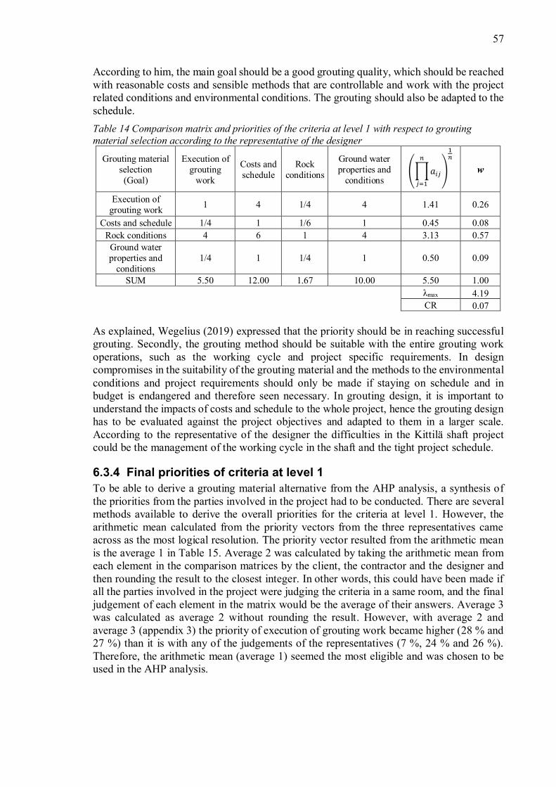
57
According to him, the main goal should be a good grouting quality, which should be reachedwith reasonable costs and sensible methods that are controllable and work with the projectrelated conditions and environmental conditions. The grouting should also be adapted to theschedule.Table 14 Comparison matrix and priorities of the criteria at level 1 with respect to groutingmaterial selection according to the representative of the designer
Grouting materialselection(Goal)
Execution ofgrouting
work
Costs andschedule
Rockconditions
Ground waterproperties and
conditionsw
Execution ofgrouting work 1 4 1/4 4 1.41 0.26
Costs and schedule 1/4 1 1/6 1 0.45 0.08Rock conditions 4 6 1 4 3.13 0.57
Ground waterproperties and
conditions1/4 1 1/4 1 0.50 0.09
SUM 5.50 12.00 1.67 10.00 5.50 1.00max 4.19
CR 0.07
As explained, Wegelius (2019) expressed that the priority should be in reaching successfulgrouting. Secondly, the grouting method should be suitable with the entire grouting workoperations, such as the working cycle and project specific requirements. In designcompromises in the suitability of the grouting material and the methods to the environmentalconditions and project requirements should only be made if staying on schedule and inbudget is endangered and therefore seen necessary. In grouting design, it is important tounderstand the impacts of costs and schedule to the whole project, hence the grouting designhas to be evaluated against the project objectives and adapted to them in a larger scale.According to the representative of the designer the difficulties in the Kittilä shaft projectcould be the management of the working cycle in the shaft and the tight project schedule.
6.3.4 Final priorities of criteria at level 1To be able to derive a grouting material alternative from the AHP analysis, a synthesis ofthe priorities from the parties involved in the project had to be conducted. There are severalmethods available to derive the overall priorities for the criteria at level 1. However, thearithmetic mean calculated from the priority vectors from the three representatives cameacross as the most logical resolution. The priority vector resulted from the arithmetic meanis the average 1 in Table 15. Average 2 was calculated by taking the arithmetic mean fromeach element in the comparison matrices by the client, the contractor and the designer andthen rounding the result to the closest integer. In other words, this could have been made ifall the parties involved in the project were judging the criteria in a same room, and the finaljudgement of each element in the matrix would be the average of their answers. Average 3was calculated as average 2 without rounding the result. However, with average 2 andaverage 3 (appendix 3) the priority of execution of grouting work became higher (28 % and27 %) than it is with any of the judgements of the representatives (7 %, 24 % and 26 %).Therefore, the arithmetic mean (average 1) seemed the most eligible and was chosen to beused in the AHP analysis.

58
Table 15 The final priorities of criteria at level 1Criteria (level 1) Client Contractor Designer Average 1 Average 2 Average 3Execution of grouting 7 % 24 % 26 % 19 % 28 % 27 %Costs and schedule 56 % 16 % 8 % 27 % 24 % 26 %Rock conditions 23 % 36 % 57 % 38 % 34 % 33 %Ground waterproperties and groutreaction to environment
14 % 24 % 9 % 16 % 14 % 13 %
6.4 The priorities of alternatives with respect to the criteriaThe comparison phase of the AHP analysis also included the comparison of alternatives withrespect to the selected criteria. In this chapter also, the criteria itself at levels 2 and 3 areprioritized. The judgements in the comparison matrices were completed with the help ofliterature research and site investigations, in addition to a questionnaire (appendix 2) andinterviews. The interviews were conducted to the aforementioned André van Wageningen,Emil Plomer and Arto Wegelius, as well as to Jari Haapala who provided a designer pointof view considering grouting. Also, a geologist, Joonas Klockars, involved in the project,was interviewed to gain understanding of the rock conditions at the Kittilä shaft site.
6.4.1 Execution of grouting workThe priorities for the criteria of execution of grouting were first obtained from therepresentative of the contractor, Emil Plomer (2019). He filled out a questionnaire (appendix2) remotely, i.e. not in an interview. Since the results from the questionnaire filled by thecontractor did not have an adequate consistency ratio (Table 16), the priorities for executionof grouting were replaced by the answers of a designer, Jari Haapala (2019), in an interviewinstead (Table 17).Table 16 The priorities of execution of grouting work, according to Plomer (2019)
Execution ofgrouting(level 1)
User-friendliness
Safety/Toxicity
Groutingequipment
Groutingmethod w
User-friendliness 1 1/7 7 1 1.00 0.22Safety/Toxicity 7 1 1 1 1.63 0.36
Grouting equipment 1/7 1 1 1/5 0.41 0.09Grouting method 1 1 5 1 1.50 0.33
SUM 9.14 3.14 14.00 3.20 4.53 1.00max 5.56
CR 0.59
Naturally the judgements and final priorities by Haapala (2019) differed from the ones ofPlomer (2019) to some extent since both represent different organizations, the designer andthe contractor. However, as mentioned the priorities from the contractor could not be useddue to the low consistency ratio. Haapala (2019) did not prioritize the toxicity or the user-friendliness/experience as highly as the contractor since according to him these are factorsthat could be influenced in beforehand the execution of grouting by education and training.The grouting method on the other hand must be rationalized with the environmental and rockconditions. The method is not something that could be altered later due to reasons of e.g.
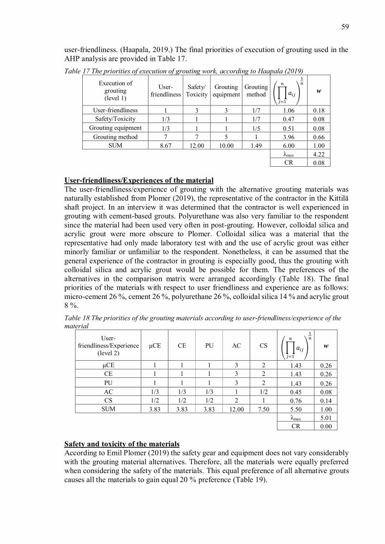
59
user-friendliness. (Haapala, 2019.) The final priorities of execution of grouting used in theAHP analysis are provided in Table 17.Table 17 The priorities of execution of grouting work, according to Haapala (2019)
Execution ofgrouting(level 1)
User-friendliness
Safety/Toxicity
Groutingequipment
Groutingmethod w
User-friendliness 1 3 3 1/7 1.06 0.18Safety/Toxicity 1/3 1 1 1/7 0.47 0.08
Grouting equipment 1/3 1 1 1/5 0.51 0.08Grouting method 7 7 5 1 3.96 0.66
SUM 8.67 12.00 10.00 1.49 6.00 1.00max 4.22
CR 0.08
User-friendliness/Experiences of the materialThe user-friendliness/experience of grouting with the alternative grouting materials wasnaturally established from Plomer (2019), the representative of the contractor in the Kittiläshaft project. In an interview it was determined that the contractor is well experienced ingrouting with cement-based grouts. Polyurethane was also very familiar to the respondentsince the material had been used very often in post-grouting. However, colloidal silica andacrylic grout were more obscure to Plomer. Colloidal silica was a material that therepresentative had only made laboratory test with and the use of acrylic grout was eitherminorly familiar or unfamiliar to the respondent. Nonetheless, it can be assumed that thegeneral experience of the contractor in grouting is especially good, thus the grouting withcolloidal silica and acrylic grout would be possible for them. The preferences of thealternatives in the comparison matrix were arranged accordingly (Table 18). The finalpriorities of the materials with respect to user friendliness and experience are as follows:micro-cement 26 %, cement 26 %, polyurethane 26 %, colloidal silica 14 % and acrylic grout8 %.Table 18 The priorities of the grouting materials according to user-friendliness/experience of thematerial
User-friendliness/Experience
(level 2)CE PU AC CS w
1 1 1 3 2 1.43 0.26CE 1 1 1 3 2 1.43 0.26PU 1 1 1 3 2 1.43 0.26AC 1/3 1/3 1/3 1 1/2 0.45 0.08CS 1/2 1/2 1/2 2 1 0.76 0.14
SUM 3.83 3.83 3.83 12.00 7.50 5.50 1.00max 5.01
CR 0.00
Safety and toxicity of the materialsAccording to Emil Plomer (2019) the safety gear and equipment does not vary considerablywith the grouting material alternatives. Therefore, all the materials were equally preferredwhen considering the safety of the materials. This equal preference of all alternative groutscauses all the materials to gain equal 20 % preference (Table 19).

60
Table 19 The priorities of the grouting materials according to safety/toxicity
Safety/Toxicity(level 2) CE PU AC CS w
1 1 1 1 1 1.00 0.20CE 1 1 1 1 1 1.00 0.20PU 1 1 1 1 1 1.00 0.20AC 1 1 1 1 1 1.00 0.20CS 1 1 1 1 1 1.00 0.20
SUM 5.00 5.00 5.00 5.00 5.00 5.00 1.00max 5.00
CR 0.00
Grouting equipmentThe representative of the contractor, Emil Plomer (2019), also, provided information aboutthe available grouting equipment on the Kittilä shaft construction site. The contractor had onsite the equipment for PU and cement grouting. According to the contractor the equipmentfor PU is quite compact and very easy to handle, therefore it is especially useful withhorizontal spot grouting. The equipment for cement grouting requires slightly more effort toset up. Therefore, the equipment for PU is slightly more user-friendly compared to theequipment used for cement-based grouts. Some additional equipment would be needed to beable to use acrylic grout and colloidal silica effectively. The available packers on site wouldbe suitable for all the materials. The comparison matrix was filled according to the
As a result, PU achieved the highest priority according to groutingequipment on the site reaching the priority of 38 %. Furthermore, CE and23 % priority followed by CS and AC with 8 % priority.
Table 20 The priorities of the grouting materials according to grouting equipment
Grouting equipment(level 2) CE CE PU AC CS w
CE 1 1 1/2 3 3 1.35 0.23CE 1 1 1/2 3 3 1.35 0.23PU 2 2 1 4 4 2.30 0.38AC 1/3 1/3 1/4 1 1 0.49 0.08CS 1/3 1/3 1/4 1 1 0.49 0.08
SUM 4.67 4.67 2.50 12.00 12.00 5.98 1.00max 5.03
CR 0.01
Grouting methodThe grouting material options were also checked to be suitable with Kittilä shaft groutingmethod, the horizontal grouting. In general, cement grout has been used successfully in bothpost- and pre-grouting, thus it can be assumed that the material suits with the shaft groutingmethod. On the other hand, the Finnish Concrete Society instructions, BY 53 (2006), statethat chemical grouting materials can be especially useful in complex grouting situations. Thesetting time of chemical grouting materials can be adjusted to be very short in which casethe materials can be suitable in difficult post-grouting (BY, 2006). The representative of the

61
Kittilä shaft project contractor, Emil Plomer (2019), also verified that e.g. PU is very usefulin horizontal spot grouting. Naturally, the grouting hole diameter and the number of holescould differ between different materials to gain an equal grouting result with all of them.However, these factors were not considered since they would need more accurate design.Furthermore, Haapala (2019) could not find a reason why any of these materials could notperform with the designed horizontal grouting method. Therefore, all the materials wereassumed to have somewhat similar suitability with the shaft grouting method, thus all thematerials in the AHP analysis gained the same 20 % priority according to grouting method(Table 21). Since all the elements of the comparison matrix became one, the consistencyratio CR became zero.Table 21 The priorities of the grouting materials according to grouting method
Grouting method(level 2) CE PU AC CS w
1 1 1 1 1 1.00 0.20CE 1 1 1 1 1 1.00 0.20PU 1 1 1 1 1 1.00 0.20AC 1 1 1 1 1 1.00 0.20CS 1 1 1 1 1 1.00 0.20
SUM 5.00 5.00 5.00 5.00 5.00 5.00 1.00max 5.00
CR 0.00
6.4.2 Costs and scheduleThe priority between the cost of grouting and the schedule influence was determined by therepresentative of the client, André van Wageningen (2019). The schedule influence wasstrongly favored with the weight of 88 % since the impacts on the schedule from the groutingcould become far more expensive than the grouting work itself. Naturally, the mine isstrongly dependent financially that the operations can start on time. Also, Wegelius (2019)emphasized that schedule alterations in the project could cause expenses that could be largerthan the grouting costs itself.Table 22 The priorities of costs and schedule, according to the representative of the client A. vanWageningen (2019)
Costs and schedule(level 1)
Groutingcosts
Scheduleinfluence w
Grouting costs 1 1/7 0.38 0.13Schedule influence 7 1 2.65 0.88
SUM 8.00 1.14 3.02 1max 2.00
CR 0.00
Grouting costsThe costs of grouting include the grouting material, the equipment and the employees neededto conduct the grouting work. Since the equipment and employees are needed in groutingwith all the grouting materials, they were ignored for the purpose of simplification.Therefore, only the costs of the materials were compared in the case Kittilä shaft. Theapproximate costs of the materials compared in the AHP analysis are listed in Table 23.

62
Table 23 Costs of the grouting materials (Babcock, 2016)Material Cost ($/gallon) Revised cost ($/gallon)
3-4 4-5CE 1-2 2PU 60-80 4-5AC 8-10 9-11CS 13-15 14-17
However, the costs of the materials usually cannot be compared directly, since theconsumption of the materials is different in the same type of environment. The first importantnotion is that PU can expand up to 20 times by volume (GCP Applied Technologies, 2018).Therefore, it was assumed that the consumption of the material could be almost 20 times lesscompared to the other materials. The consumption of the grouts with smaller particle sizecould on the other hand be higher than the one of grouts with larger particle size since thesmaller particle size provides for better penetrability. Therefore, it is assumed that therelative consumption of acrylic grout and colloidal silica is minorly higher than the one ofthe other grouting materials. The consumption of cement grout on the other hand could besmaller than the consumption of the other materials, because of the larger particle size.However, due to needed sulfate resistance of the cementitious grouts their price could alsoincrease compared to non-sulfate resistant cements.
In reality, the different grouting materials would have different type of grouting patterns andthe consumption of the materials would depend on the environmental and rock conditions.For the purpose of simplifications, the aforementioned approximations were used in the costanalysis and revised costs (Table 23) were used when comparing the materials in thecomparison matrix (Table 24). The priorities of the materials according to grouting costsbecame as follows: CE 43 %, and PU 22 %, AC 8 % and CS 5 %.Table 24 The priorities of the grouting materials according to grouting costs
Grouting costs(level 2) CE PU AC CS w
1 1/2 1 3 4 1.43 0.22CE 2 1 2 5 8 2.76 0.43PU 1 1/2 1 3 4 1.43 0.22AC 1/3 1/5 1/3 1 2 0.54 0.08CS 1/4 1/8 1/4 1/2 1 0.33 0.05
SUM 4.58 2.33 4.58 12.50 19.00 6.49 1.00max 5.02
CR 0.00
Schedule impacts of groutingThe grouting method used in the AHP analysis is the horizontal grouting presented in chapter6.1.3. In the horizontal grouting the grouting is conducted in the shaft either before or afterbolting yet after safety shotcreting. Since the reaction times can be easily adjusted for all thechemical grouting materials (Haapala, 2019), the schedule impacts of these materials wereassumed to be equal. Haapala (2019) pointed out that with cementitious grouts the executionof grouting is slower than with chemical grouts, and furthermore, even larger grouting holeswould be needed. The schedule impact of and CE were assumed equal since the
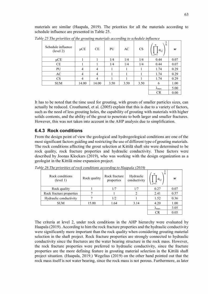
63
materials are similar (Haapala, 2019). The priorities for all the materials according toschedule influence are presented in Table 25.Table 25 The priorities of the grouting materials according to schedule influence
Schedule influence(level 2) CE PU AC CS w
1 1 1/4 1/4 1/4 0.44 0.07CE 1 1 1/4 1/4 1/4 0.44 0.07PU 4 4 1 1 1 1.74 0.29AC 4 4 1 1 1 1.74 0.29CS 4 4 1 1 1 1.74 0.29
SUM 14.00 14.00 3.50 3.50 3.50 6 1.00max 5.00
CR 0.00
It has to be noted that the time used for grouting, with grouts of smaller particles sizes, canactually be reduced. Crouthamel, et al. (2005) explain that this is due to a variety of factors,such as the need of less grouting holes, the capability of grouting with materials with highersolids contents, and the ability of the grout to penetrate to both larger and smaller fractures.However, this was not taken into account in the AHP analysis due to simplification.
6.4.3 Rock conditionsFrom the design point of view the geological and hydrogeological conditions are one of themost significant factors guiding and restricting the use of different type of grouting materials.The rock conditions affecting the grout selection at Kittilä shaft site were determined to berock quality, rock fracture properties and hydraulic conductivity. These factors weredescribed by Joonas Klockars (2019), who was working with the design organization as ageologist in the Kittilä mine expansion project.Table 26 The priorities of rock conditions according to Haapala (2019)
Rock conditions(level 1) Rock quality Rock fracture
propertiesHydraulic
conductivity w
Rock quality 1 1/7 1/7 0.27 0.07Rock fracture properties 7 1 2 2.41 0.57Hydraulic conductivity 7 1/2 1 1.52 0.36
SUM 15.00 1.64 3.14 4.20 1.00max 3.05
CR 0.05
The criteria at level 2, under rock conditions in the AHP hierarchy were evaluated byHaapala (2019). According to him the rock fracture properties and the hydraulic conductivitywere significantly more important than the rock quality when considering grouting materialselection in the shaft project. Rock fracture properties are strongly connected to hydraulicconductivity since the fractures are the water bearing structure in the rock mass. However,the rock fracture properties were preferred to hydraulic conductivity, since the fractureproperties are the more defining feature in grouting material selection in the Kittilä shaftproject situation. (Haapala, 2019.) Wegelius (2019) on the other hand pointed out that therock mass itself is not water bearing, since the rock mass is not porous. Furthermore, as later

64
explained, the rock mass quality at Kittilä shaft construction site is fairly good. This can alsobe seen in the judgements of Haapala (2019). The priorities of Haapala show only a 7 %preference to rock quality in comparison with rock fracture properties with 57 % preferenceand hydraulic conductivity with 36 % preference. The final priorities are presented in Table26.
Rock qualityAccording to Kittilä shaft project geologist, Joonas Klockars (2019), in general the rockmass in the Kittilä shaft area can be described as fair in the rock mass quality system (Q-classification). The rock type is mainly massive pillow lava (MPL) and massive basalt(MML). The rock originates from massive extrusive igneous rock that has underwent sometype of metamorphosis. According to the Finnish RG-classification the rock mass is slightlyfoliated, and massive or mixed composition rock. (Klockars, 2019.)
The rock mass, however, contains weak and fragmented zones. In these types of areas, therock mass is poor or very poor according to Q-classification. Also, the top 5-10 meters ofthe bedrock is very fragmented and weathered, after which the rock type changes drasticallyto solid rock. In the weak zones the jointing is tens of fractures per meter, whereas thejointing in the fairly good rock mass is 3-10 joints per meter. (Klockars, 2019.)
According to Haapala (2019), PU would be the worst material according to rock quality,since its use is preferred in situations with large water ingress that require fast reaction times.This applies especially when PU is considered as the primary grouting material for the fulllength of the shaft. When considering the fragmented zones in the rock, cement could be thebest solution since it could possibly improve the rock characteristics in weak rock. Micro-cement would be the second-best material when considering the idea that Barton et al. (2001,cited in Tolppanen & Syrjänen, 2003) have on rock mass property improvement withgrouting. AC and CS do not have such properties of rock mass improvement, neither doesPU. Therefore, the final priorities of the grouting materials according to rock quality are asfollows: CE 43 %, 27 %, AC and CS 12 %, and PU 6 % (Table 27).Table 27 The priorities of the grouting materials according to rock quality
Rock quality(level 2) CE PU AC CS w
1 1/3 5 3 3 1.72 0.27CE 3 1 5 3 3 2.67 0.43PU 1/5 1/5 1 1/2 1/2 0.40 0.06AC 1/3 1/3 2 1 1 0.74 0.12CS 1/3 1/3 2 1 1 0.74 0.12
SUM 4.87 2.20 15.00 8.50 8.50 6.26 1.00max 5.15
CR 0.03
Haapala (2019) pointed out that the possible strengthening of weak rock mass is notconsidered in the reainforcement design in the shaft. However, the idea of achieving a moremassive rock mass is a convinient addition (Haapala, 2019). Naturally, it is possible tofragment the rock by using high pressures in grouting. Yet Wegelius (2019) remarked thatthe rock mass in Kittilä shaft project is fairly good, thus he would not be concerned of hydro-jacking. The more relevant factors in achieving a dry shaft is the type of rock fractures, their

65
apertures, directions and possible joint fillings, and the volume of water ingress and itspressure.
Rock fracture propertiesIn general, the rock mass at Kittilä shaft site include three to four main orientations of joints,i.e. joint sets. The fracture types can be described as (i) sub-vertically positioned fractures,(ii) sub-horizontally positioned fractures, (iii) low-gradient fractures and (iv) fractures in theorientation of foliation. (Klockars, 2019.)
The sub-vertical fractures are typically graphite filled or coated and can appear as anaccumulation of fractures. This type of areas with many graphite fractures are called graphitefault zones (GFZs). These GFZs are often intersected by perpendicular, sub-horizontal,fractures. The sub-horizontal and low-gradient fractures are often connected with the wateringress zones in the shaft. Besides their water-bearing characteristic, they can also beconnected with weak or weathered rock zones. The rock quality can be especially poor whenthe sub-horizontal and sub-vertical fracture zones intersect with each other. The foliation hastypically an orientation of 45/090 (dip/dip direction). (Klockars, 2019.)
The rock fracture properties were divided into fracture aperture, fracture network propertiesand joint filling. The preferences between these aforementioned properties were evaluatedby Haapala (2019) (Table 28). According to Haapala (2019) the most important feature toconsider from the rock fracture properties was the fracture network by 64 %. The joint fillingwas the next most important factor to take into account by 26 %. The preference of fractureaperture only gained 10 % importance.Table 28 The priorities of rock fracture properties, according to Haapala (2019)
Rock fracture properties(level 2)
Fractureaperture
Fracturenetwork Joint filling w
Fracture aperture 1 1/5 1/3 0.41 0.10Fracture network 5 1 3 2.47 0.64
Joint filling 3 1/3 1 1.00 0.26SUM 9.00 1.53 4.33 3.87 1.00
max 3.02CR 0.01
In order to be able to evaluate the suitability of different grouting materials with the fractureaperture in the first shaft section, the fracture aperture properties of the rock mass had to bedetermined. The drill core sample STEC12009 from ground level to level -763 was logged,and an optical borehole imaging (OBI) was conducted in the borehole. From the OBI thefracture apertures were measured, and fracture types collected. The fracture opening sizes ofopen fractures, fractures with rough-grained filling and cracks inside larger features wereidentified from the first shaft section, levels - -325.1. Figure 17 represents thedifferent types of open fractures and their apertures by borehole depth. The true depth of theshaft in the mine coordinate system is the vertical axis on the right in the figure.
The average determined fracture opening size was 10.45 mm. However, the largest fracturesare part of weakness zones, thus the fracture aperture value of this type of rock zones doesnot describe the aperture of one single fracture. Also, the total amount of this type offracturing is minimal compared to the total amount of fractures. Therefore, the median value

66
of 1.00 mm and the mode value of 0.5 mm better describe the actual aperture of existingfractures. The median is the middle value when the data set is arranged from smallest tolargest and the mode describes the most frequently appearing value in the data set. If singlefractures with the opening size over 5 mm are ignored the average fracture aperture becomes1.12 mm. This value describes the average aperture more accurately since only eightfractures in the section 1 of the shaft were labeled with larger than 5 mm aperture. Theaperture division of fractures of < 5 mm apertures are shown in Figure 18.
Figure 17 Fracture apertures and types by borehole depth in shaft section 1. True depth is anapproximation from borehole data. (Data to table from SRK Consulting Oy, 2017 and DrillconSMOY, 2012.)
10
35
60
85
110
135
160
185
210
235
260
285
310
335
0
25
50
75
100
125
150
175
200
225
250
275
300
3250 20 40 60 80 100 120 140
True
dep
th (m
)
Bore
hole
dep
th (m
)
Fracture aperture (mm)
Shaft: section 1Fracture apertures and types by depth
Open fractures Fracture with rough-grained filling Cracks inside larger feature True_depth

67
Figure 18 Fracture apertures and types of fractures with aperture < 5 mm by borehole depth inshaft section 1. True depth is an approximation from borehole data. (Data to table from SRKConsulting Oy, 2017 and Drillcon SMOY, 2012.)
The rule of thumb in selecting the grouting material is that the d95 should be not more than of the fracture opening size (BY, 2006). Therefore, all of the grouting materials could
be suitable for grouting in Kittilä shaft according to average fracture aperture. However,Haapala (2019) would prefer the use of cement-based grouts. Also, according to Plomer(2019), the fractures in question should not be countable as micro-cracks thus he would notprefer the use of the finer materials. The final priorities of the materials according to thefracture aperture obtained from the judgements of Haapala (2019) are as follows (Table 29):µCE 50 %, CE 25 %, PU 15 %, and AC and CS 5 %.Table 29 The priorities of the grouting materials according to fracture aperture
Fracture aperture(level 3) CE PU AC CS w
1 3 5 7 7 3.74 0.50CE 1/3 1 3 5 5 1.90 0.25PU 1/5 1/3 1 5 5 1.11 0.15AC 1/7 1/5 1/5 1 1 0.36 0.05CS 1/7 1/5 1/5 1 1 0.36 0.05
SUM 1.82 4.73 9.40 19.00 19.00 7.47 1.00max 5.29
CR 0.07
The fracture network at Kittilä shaft site was also investigated for the purpose of groutselection. The network description includes frequency of fissure and the direction of them,that is basically the 3D-network which the fractures create. As mentioned, the rock mass has
10356085110135160185210235260285310335
0255075
100125150175200225250275300325
0 0.5 1 1.5 2 2.5 3
True
dep
th (m
)
Bore
hole
dep
th (m
)
Fracture aperture (mm)
Shaft: section 1Fracture apertures and types by depth
Fracture aperture < 5 mm
Open fractures Fracture with rough-grained filling Cracks inside larger feature True_depth

68
generally 3-4 main orientations of joints and the fairly good to good rock mass includesapproximately 3-10 fractures per meter. According to the Finnish RG-classification the rockmass is therefore described as high-fissured. The most typical type of fracturing is thegraphite filled or coated fractures, which were also connected to the weakness zones in therock (GFZs). In weakness zones also joints with different directions often intersect with eachother. (Klockars, 2019.)
The Figure 17 and Figure 18 also show the general distribution of fracturing in the firstsection of the shaft. The figures show that this stretch of the shaft includes areas with morefractures and some areas with less open of filled fractures. According to Haapala (2019) it isquite hard to judge the material suitability according to the fracture network since it iscomplicated and changes throughout the whole length of the shaft. However, he wouldstrongly prefer to CE since it has better penetrability in less frequently fractured rock.PU would be the second-best material after . The final priorities according to fracturenetwork by Haapala are presented in Table 30.Table 30 The priorities of the grouting materials according to fracture network
Fracture network(level 3) CE PU AC CS w
1 5 5 3 3 2.95 0.49CE 1/5 1 1 2 2 0.96 0.16PU 1/5 1 1 2 2 0.96 0.16AC 1/3 1/2 1/2 1 1 0.61 0.10CS 1/3 1/2 1/2 1 1 0.61 0.10
SUM 2.07 8.00 8.00 9.00 9.00 6.08 1.00max 5.24
CR 0.05
Also, the fracture fillings were analyzed from the drill core sample STEC12009 anddescribed by J. Klockars (2019). The graphite fractures are the most common fracture fillingor coating, even though these types of fractures are not otherwise that common. The graphitecan also emerge as a very slippery coating in the fracture. However, also carbonate, chloriteand asbestos-mineral filled fractures exist. The carbonate filled fractures mostly appear inthe direction of the rock mass foliation where light-colored and a few millimeters thickcarbonate veins exist. (Klockars 2019.)
Klockars (2019) described most of the fractures to have a coating or alteration. Only ahandful of fractures could be described as open fractures without fillings. Some uncertaintiesin the interpretation of joint fillings exist. Some of the filling materials may have washed outwhen the bore hole sample was drilled, and the shaft was reamed. It can also be very difficultto judge filling materials and its existence from the OBI analysis of STEC12009 from whichthese findings stem from. Nevertheless, the interpretation of the OBI analysis showed astrong connection between the fractures labeled with sand or gravel infillings and with wateringress volumes. (Klockars, 2019.)
The grouting materials were evaluated in respect to joint filling by Haapala (2019). Haapala(2019) preferred micro-cement to polyurethane because with fracture fillings the micro-cement has higher probability to penetrate further in the fracture. However, Polyurethanewas preferred to standard cement. Acrylic grout and colloidal silica were found to be second

69
best after micro-cement since these products also provide for better penetrability withfracture fillings. He also added that since the joint filling is not stopping the water flow andthere is still a relatively steady water ingress volume, acrylic grout and colloidal silica couldbe too fine materials for the fractures. This would suggest the use of micro-cement. The finalpriorities of the materials according to joint filling are provided in Table 31.Table 31 The priorities of the grouting materials according to joint filling
Joint filling(level 3) CE PU AC CS w
1 5 3 2 2 2.27 0.39CE 1/5 1 1/2 1/3 1/3 0.41 0.07PU 1/3 2 1 1/2 1/2 0.70 0.12AC 1/2 3 2 1 1 1.25 0.21CS 1/2 3 2 1 1 1.25 0.21
SUM 2.53 14.00 8.50 4.83 4.83 5.86 1.00max 5.02
CR 0.00
Hydraulic conductivityThe flowing of water can also influence the grouting material selection. Some materials andmaterial mixes might need a longer setting time or might leach.
According to Klockars (2019) the sub-vertically positioned fractures are working as thewater-bearing network in the rock mass, and the sub-horizontal fractures work as the water-storages in which the water flow is slower. Since the shaft opening has been reamed, thestored water is now free to flow into the empty shaft hole. This could also have caused thejoint fillings to wash out more. All in all, at this point the horizontally positioned fracturesare mostly bearing the water into the shaft. (Klockars, 2019.)
As mentioned, the leakages in the shaft are mostly connected with horizontal fractures.Klockars (2019) points out that the source of the leakage can be either one single fracturefrom millimeters to a centimeter or a zone of parallel horizontal fractures. Nevertheless, theleakage amount is strongly connected to the fracture aperture. (Klockars, 2019.)
According to Klockars (2019), the pressures of the leaking water are not major. Themeasured estimate of the leakage of the first, approximately 305 m long, section of the shaftis 10 m3/h (Klockars, 2019) which is approximately 55 l/min/100m.
When it comes to the most suitable grouting materials considering the hydraulic conductivityat Kittilä shaft site, Haapala (2019) would prefer cement-based grouting materials. If thewater ingress would be low, he would prefer the use of AC and CS. Also, Plomer (2019)supported this statement. According to him CS would need a longer setting time in groutingthan the cement-based grouts. In the shaft a water flow is already created after the reamingphase of the shaft that could have washed out the grouting material. For pre-groutingpurposes CS would work quite well in the shaft. (Plomer, 2019.) PU reacts with water, thusthe successful grouting with it would need the packer to be set relatively deep in the groutinghole (Haapala, 2019). However, PU would be a good option when large leakages are inquestion (Plomer, 2019). The final priorities judged by Haapala (2019) are presented inTable 32.

70
Table 32 The priorities of the grouting materials according to hydraulic conductivity
Hydraulicconductivity
(level 2)CE PU AC CS w
1 2 5 7 7 3.45 0.49CE 1/2 1 3 4 4 1.89 0.27PU 1/5 1/3 1 2 2 0.77 0.11AC 1/7 1/4 1/2 1 1 0.45 0.06CS 1/7 1/4 1/2 1 1 0.45 0.06
SUM 1.99 3.83 10.00 15.00 15.00 7.00 1.00max 5.03
CR 0.01
6.4.4 Groundwater properties and conditionsThe groundwater conditions at Kittilä shaft site were measured by a groundwater sample(S350KUILU) taken from approximately level -350 from a shaft finger drift on 3.9.2018.Since this is only one sample from one depth in the shaft, the results and interpretation fromthe sample are indicative generalizations. Some of the characteristics of the groundwatersample are presented in Table 33.Table 33 Some of the results from the groundwater sample S350KUILU
Measured variable Measured value UnitTemperature 7.0 °CpH 7.8Sulfate (SO4
2-) 1300 mg/lChlorine (Cl) 41 mg/lCalcium (Ca) 290 mg/lSodium (Na) 34 mg/l
In the AHP hierarchy the criterion of groundwater properties and conditions at criteria level1 were divided into two subcriteria, grout effects on the environment and, on the contrary,groundwater impacts on the grout. It was determined by Arto Wegelius (2019), that thepriority of groundwater impacts on the grout is more important than the grout effects on theenvironment, thus the first mentioned received the priority of 67 % and the latter 33 %respectively from the comparison matrix (Table 34). A. Wegelius (2019) justified thepriorities by reminding that the volumes of grouting conducted in the Kittilä shaft isrelatively small. If massive grouting to the whole mine facility would have been inconsideration, the environmental load would be much larger. In that case, the environmentalloading from the grouting should be considered more profoundly. However, in this shaft casethe groundwater impacts on the grout are more critical.

71
Table 34 The priorities of groundwater properties and conditions, according to the representativeof the designer
Groundwaterproperties and
conditions (level 1)
Grouteffects on
environment
Groundwaterimpacts on
groutw
Grout effects onenvironment 1 1/2 0.71 0.33
Groundwaterimpacts on grout 2 1 1.41 0.67
SUM 3.00 1.50 2.12 1.00max 2.00
CR 0.00
Grout effects on the environmentAs Wegelius (2019) mentioned the scale of the grouting conducted in the shaft is not massivepre-grouting but localized horizontal grouting into leaking areas in the shaft. This knowledgecombined with the rural location of the mine creates a situation in which the environmentalload of the grouting is not substantial, especially compared with e.g. grouting worksconducted in a metro tunnel in a city area. Furthermore, the grouting materials selected tothe AHP analysis are ones without environmentally hazardous features. This minimizes therisks that could be associated with the grouting.
Thereby, the effects of the different grouting materials in the AHP analysis were consideredto be similar to the environment, even though some of the materials may change theproperties of the groundwater in some ways. Hence, the possible local changes in thegroundwater due to shaft grouting were considered insignificant regarding the whole mineenvironment. For example, the pH level in groundwater surrounding the cement-groutedzones is known to increase, yet the impact of that increase is quite negligible considering allthe groundwater without an increase of pH in the mine area. All the materials receivedidentical priorities from the comparison matrix with respect to grout effects on theenvironment (Table 35).Table 35 The priorities of the grouting materials according to grout effects on environment
Grout effects onenvironment (level 2) CE PU AC CS w
1 1 1 1 1 1.00 0.20CE 1 1 1 1 1 1.00 0.20PU 1 1 1 1 1 1.00 0.20AC 1 1 1 1 1 1.00 0.20CS 1 1 1 1 1 1.00 0.20
SUM 5.00 5.00 5.00 5.00 5.00 5.00 1.00max 5.00
CR 0.00
Groundwater impacts on the groutThe main characteristic that could cause concern for successful grouting at Kittilä shaft sitewas detected to be sulfate. In general, the concentration results of the groundwater samplewere quite moderate, and so, the most distinct factor striking from the results was the sulfate(SO4
2-) concentration in the sample. The sulfate concentration in the groundwater sample
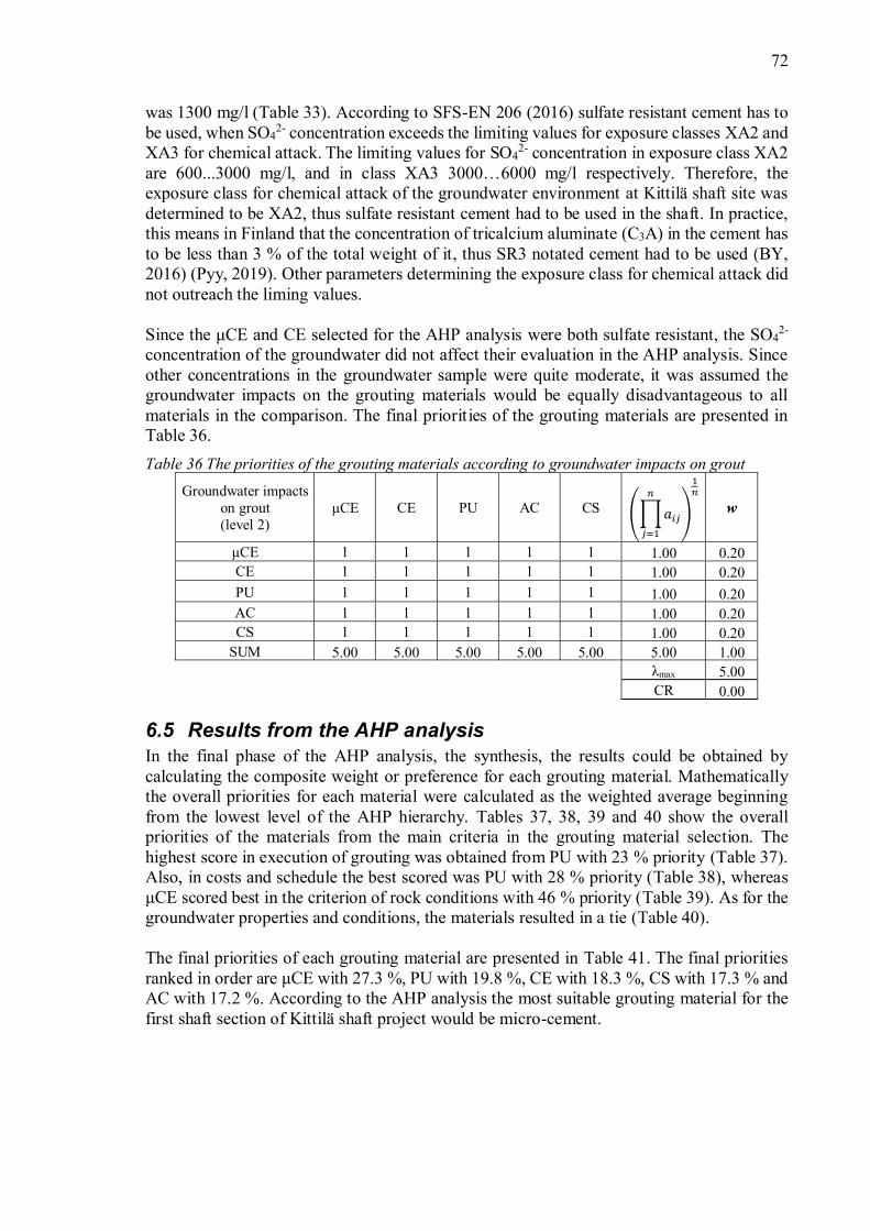
72
was 1300 mg/l (Table 33). According to SFS-EN 206 (2016) sulfate resistant cement has tobe used, when SO4
2- concentration exceeds the limiting values for exposure classes XA2 andXA3 for chemical attack. The limiting values for SO4
2- concentration in exposure class XA2are 600...3000 mg/l, and in class XA3 6000 mg/l respectively. Therefore, theexposure class for chemical attack of the groundwater environment at Kittilä shaft site wasdetermined to be XA2, thus sulfate resistant cement had to be used in the shaft. In practice,this means in Finland that the concentration of tricalcium aluminate (C3A) in the cement hasto be less than 3 % of the total weight of it, thus SR3 notated cement had to be used (BY,2016) (Pyy, 2019). Other parameters determining the exposure class for chemical attack didnot outreach the liming values.
Since the and CE selected for the AHP analysis were both sulfate resistant, the SO42-
concentration of the groundwater did not affect their evaluation in the AHP analysis. Sinceother concentrations in the groundwater sample were quite moderate, it was assumed thegroundwater impacts on the grouting materials would be equally disadvantageous to allmaterials in the comparison. The final priorities of the grouting materials are presented inTable 36.Table 36 The priorities of the grouting materials according to groundwater impacts on grout
Groundwater impactson grout(level 2)
CE PU AC CS w
1 1 1 1 1 1.00 0.20CE 1 1 1 1 1 1.00 0.20PU 1 1 1 1 1 1.00 0.20AC 1 1 1 1 1 1.00 0.20CS 1 1 1 1 1 1.00 0.20
SUM 5.00 5.00 5.00 5.00 5.00 5.00 1.00max 5.00
CR 0.00
6.5 Results from the AHP analysisIn the final phase of the AHP analysis, the synthesis, the results could be obtained bycalculating the composite weight or preference for each grouting material. Mathematicallythe overall priorities for each material were calculated as the weighted average beginningfrom the lowest level of the AHP hierarchy. Tables 37, 38, 39 and 40 show the overallpriorities of the materials from the main criteria in the grouting material selection. Thehighest score in execution of grouting was obtained from PU with 23 % priority (Table 37).Also, in costs and schedule the best scored was PU with 28 % priority (Table 38), whereas
scored best in the criterion of rock conditions with 46 % priority (Table 39). As for thegroundwater properties and conditions, the materials resulted in a tie (Table 40).
The final priorities of each grouting material are presented in Table 41. The final prioritiesranked in order are with 27.3 %, PU with 19.8 %, CE with 18.3 %, CS with 17.3 % andAC with 17.2 %. According to the AHP analysis the most suitable grouting material for thefirst shaft section of Kittilä shaft project would be micro-cement.

73
Table 37 The overall priorities of the grouting materials according to execution of grouting workCriteria level 1 Execution of grouting work
SUM(weightedaverage)Criteria level 2
User-friendliness Safety/Toxicity Grouting
equipmentGroutingmethod
0.18 0.08 0.08 0.660.26 0.20 0.23 0.20 0.21
CE 0.26 0.20 0.23 0.20 0.21PU 0.26 0.20 0.38 0.20 0.23AC 0.08 0.20 0.08 0.20 0.17CS 0.14 0.20 0.08 0.20 0.18
Table 38 The overall priorities of the grouting materials according to costs and scheduleCriteria level 1 Costs and schedule
SUM(weightedaverage)Criteria level 2
Grouting costs Scheduleinfluence
0.13 0.880.22 0.07 0.09
CE 0.43 0.07 0.12PU 0.22 0.29 0.28AC 0.08 0.29 0.26CS 0.05 0.29 0.26
Table 39 The overall priorities of the grouting materials according to rock conditionsCriteria level 1 Rock conditions
SUM(weightedaverage)
Criteria level 2Rock
quality Rock fracture properties Hydraulicconductivity
0.07 0.57 0.36
Criteria level 3 -Fractureaperture
Fracturenetwork
Jointfilling -
0.10 0.64 0.260.27 0.50 0.49 0.39 0.49 0.46
CE 0.43 0.25 0.16 0.07 0.27 0.21PU 0.06 0.15 0.16 0.12 0.11 0.13AC 0.12 0.05 0.10 0.21 0.06 0.10CS 0.12 0.05 0.10 0.21 0.06 0.10

74
Table 40 The overall priorities of the grouting materials according to groundwater properties andconditions
Criteria level 1 Groundwater properties andconditions SUM
(weightedaverage)Criteria level 2
Grout effectson environment
Groundwaterimpacts on grout
0.33 0.670.20 0.20 0.20
CE 0.20 0.20 0.20PU 0.20 0.20 0.20AC 0.20 0.20 0.20CS 0.20 0.20 0.20
Table 41 The final priorities of the grouting materials from the AHP analysisGoal Grouting material selection
SUM(weightedaverage)Criteria level 1
Execution ofgrouting work
Costs andschedule
Rockconditions
Groundwater propertiesand conditions
0.19 0.27 0.38 0.160.21 0.09 0.46 0.20 0.273
CE 0.21 0.12 0.21 0.20 0.183PU 0.23 0.28 0.13 0.20 0.198AC 0.17 0.26 0.10 0.20 0.172CS 0.18 0.26 0.10 0.20 0.173

75
7
7.1 Discussion of the literature review and the AHP hierarchyThe primary objective of this study was to determine the suitability of the AHP for groutingmaterial selection. In other words, it was tested if AHP can deliver the most optimizedgrouting material out of a definite number of alternatives. In this case the most optimizedgrouting material alternative would be the one that would with highest probability create theleast amount of problems in the project conditions and requirements. For the purpose of thestudy the AHP methodology was implemented into grouting material selection bydeveloping an elemental hierarchy for the analysis. The created hierarchy for the AHP wasthen tested in a real-life case study, the Kittilä shaft project.
The objective of the literature research was to support the objective of determining the AHPsuitability for grouting material selection. In the literature research it was established that awide range of both cementitious and chemical grouting materials are available on themarkets. Usually, the cheaper cement-based materials are selected for pre-grouting purposesand in post-grouting the chemical materials are used to complement the pre-grouting byhigher penetrability capacities. The modern-day chemical grouts are polyurethane, colloidalsilica and acrylics (Halls, 2016, cited in Hänninen, 2017). Based on the literature study, themost common grouting material, i.e. cement, and the aforementioned modern-day chemicalgrouting materials were selected for the AHP analysis in the case study.
The basic concept of the hierarchy needed for the grouting material optimization was createdin chapter 5. In the end the hierarchy was divided into four main criteria: (i) Execution ofgrouting work, (ii) costs and schedule, (iii) rock conditions and (iv) groundwater propertiesand conditions. These criteria were then divided further into subcriteria to enable pairwisecomparison of grouting materials at the lowest level needed.
The generated hierarchy (Figure 10) is only a subjective proposal that could be implementedinto grouting material selection. Naturally, not all of the existing criteria for the selection ofa grouting material could be added to the hierarchy developed for the purpose of AHPanalysis. It is very likely that another decision-maker would have constructed the hierarchydifferently. Even Saaty (2008) describes the construction of the hierarchy being the mostcreative part of the AHP method. However, it can be assumed that the created hierarchyincludes references of the important criteria needed for an accurate AHP analysis in groutingmaterial selection. Opinions and views of various grouting designers were gathered alongthe process of developing the hierarchy to ensure the functionality of it. Also, literature wasanalyzed to ensure that the most valuable criteria needed for grout selection was added tothe hierarchy.
It must be noted that the functionality of the hierarchy has to be checked according to therequirements and needs of the underground construction projects it is implemented into. Thedeveloped hierarchy was also only constructed for the comparison of cementitious groutsand environmentally friendly chemical grouting materials; polyurethane, colloidal silica andacrylic grout. If the hierarchy is used to evaluate any other grouting materials a moreprofound evaluation of the criteria in the hierarchy must be made. It is possible that othergrouting materials outside of the scope could e.g. have different environmental restrictionthan the aforementioned materials.

76
7.2 Analysis of the case studyThe results of the AHP analysis of the case study show that micro-cement would be the mostoptimized material for the grouting purposes of the first shaft section in Kittilä shaft project.This micro-cement was also the material that was selected for grouting purposes of theproject by the design organization before the AHP analysis was made. This suggests that theAHP analysis can give reliable results when it is implemented into grouting materialselection. Also, current experiences from the contractor in the project support the resultsfrom the AHP analysis. According to the contractor grouting has been conductedsuccessfully with both micro-cement and polyurethane in the shaft (Plomer, 2019).Polyurethane has been used to spot-grouting purposes in zones with large volumes of wateringress (Plomer, 2019). The other alternative grouting materials have not been tested in theshaft.
The case example used for the evaluation of the suitability of the AHP method for groutingmaterial selection was not the most traditional one. Tunnel construction in general is morecommon in Finland than deep hoisting shaft construction. Therefore, the results from thecase analysis cannot be entirely functional with more traditional tunnel grouting. Also, theanalysis was conducted for post-grouting material selection and as such it cannot be expectedto give absolutely similar results when implemented into pre-excavation grouting.Furthermore, the number of grouting material alternatives was limited in the AHP analysis.The analysis was only conducted to five different grouting materials, since the analysis oflarger numbers of materials would have been more time-consuming. A larger number ofalternatives could also have caused the probability of higher inconsistencies to occur in thejudgements.
The AHP analysis in the case study was conducted for the first section of the shaft betweenlevels -analysis can only be assumed to function for the shaft section in question. For example, thedensity of the rock fracturing can vary according to depth. Furthermore, it is known that thegroundwater properties can change according to depth, e.g. salinity increases by depth(Gustafson, et al., 2008). In the end, the changing properties of the environment could meanthat another material could be more suitable to the other parts of the shaft. However, also thefirst ranked micro-cement could be a suitable option. An AHP analysis could be conductedto the deeper parts of the shaft to see whether micro-cement would be the first rankedmaterial also there.
In the AHP analysis, the materials sometimes scored a tie with respect to some criteria. Thisoccurred with grouting method and safety/toxicity at criteria level 2 and the groundwaterproperties and conditions at criteria level 1 and further with the subcriteria below it. Thissuggests that these aforementioned criteria were of no use in the grouting material selectionfor Kittilä shaft project. These criteria were, however, kept in the analysis since it could havenot been predicted in advance in the beginning of the case study without the expertinterviews and analysis. For example, the suitability of the materials with the utilizedhorizontal grouting method had to be evaluated by a designer. Furthermore, withoutprofound understanding of all the aspects affecting to the grout selection in the Kittilä shaftproject, the selection of only necessary criteria would have been challenging. One of thegreat advantages of the AHP analysis, is that an excess number of criteria can be used in thebeginning of the analysis, and later in the analysis unnecessary criteria can be excluded.

77
As mentioned, the result of the AHP analysis in the case suggest that micro-cement wouldbe the best suitable material for the grouting purposes of Kittilä shaft project. The other fourmaterials all scored within 2.6 percentage units (Table 41), thus their ranking was very even.The problem with very even ranking of the materials is that even small changes in any of thejudgements made along the AHP analysis could change their ranking. If there would nothave been one material, micro-cement, outranking the other materials, the results would havebeen rather inconclusive. Therefore, the secondly ranked material could be as wellperforming material in the Kittilä shaft project as the latter three, at least according to theAHP analysis.
Also, the primary suggestion of micro-cement from the AHP analysis cannot be taken tooliterally. Naturally, a MCDM-tool as the AHP cannot guarantee that the primarily scoredmaterial would work smoothly in grouting at Kittilä shaft site. The AHP analysis cannotensure that the grouting in the shaft will be adequate according to the waterproofingrequirements. The analysis can only suggest for the most suitable or optimal material for thepurpose of grouting. Furthermore, the analysis can only rank the materials chosen for theanalysis according to the criteria used in the analysis. If any criteria in the analysis would bedetermined as irrelevant or any criteria outside of the analysis would need to be added to theAHP hierarchy, the ranking of the materials could change. Any errors in the judgementscould also provide for different results from the analysis. Also, it is not given that no othermaterial outside of the materials used in the analysis could not work as well as the firstranked material. Logically, very similar materials to micro-cement used in the analysis(Injektering 30) could be as suitable for the shaft grouting.
The judgments in the AHP analysis were made carefully with the help of literature, siteinvestigation results and expert interviews. However, many simplifications had to be madeand not all of the judgements made in the analysis can be perfectly absolute. For, example,the costs of the materials were taken from a literature source, and they were modified torevised costs (Table 23) according to assumptions of the material consumptions. In allprobability the most accurate way of analyzing the cost could have been made by modifyingthe grouting design accurately to each material need and requesting for tender offers for eachmaterial from contractors. However, this would have been exaggerated and a needless effortwhen considering the overall accuracy of the AHP analysis. Also e.g. the groundwaterimpacts on grout had to be made with the available experience. For instance, only onegroundwater sample from the Kittilä shaft site was analyzed. In reality, to get more detailedoverall knowledge of the chemical properties of the groundwater, multiple groundwatersamples would have been needed for the analysis. The only evident factor defined from thesample that could affect the grouting material selection was the sulfate concentration.Nevertheless, once again the results from the groundwater sample provided for sufficientimpression of the general quality of the groundwater for the AHP.
The uppermost observation from the expert interviews, in which the client representative,the contractor representative and the two designers evaluated the chosen alternatives andcriteria with the AHP method, was that all of the interviewees experienced the evaluation ofelements somewhat challenging. The first observed problem for the interviewees was tojudge the alternative grouting materials only according to one criterion at a time. The reasonfor this was the connections found within the chosen criteria. For example, the hydraulicconductivity of the rock mass is strongly connected with the fracture network properties andthe fracture aperture. Traditionally, in design work the grouting materials are not evaluated

78
according to these attributes individually but as a whole. The second observations in theinterviews was the difficulty of attaining consistent results. Consistent results were moreeasily collected when the interviewee understood the basic mathematics behind the AHPmethod. Independently and remotely filled AHP questionnaires provided for weakerinconsistencies in results than judgements made in an interview type of situation. Collectingconsistent results remotely could have become troublesome.
The interviews of the different parties in the project showed that the client, the contractorand the designer can have diverse concepts of what type of criteria should be mostemphasized in the AHP analysis, possibly in construction projects in general too. Thisphenomenon was somewhat expected and can be viewed in Figure 19. As it can be seen therepresentative of the client strongly preferred cost and schedule, whereas the representativeof the designer preferred the importance of rock conditions in the grouting material selection.The preferences of the representative of the contractor were more even between the differentcriteria. In the end it was chose to use the arithmetic mean of the preferences of the differentparties, i.e. average 1 in the figure. Averages 2 and 3 in the figure are explained in moredetail in chapter 6.3.4.
Figure 19 Preferences of the criteria (level 1) by different parties in the project.
It must also be noted that the grouting material alternatives and the criteria were onlyevaluated by one expert at a time and not a group of them. This could cause that the madejudgements do not represent the general views of the different parties involved in the project.It could even be possible that these interviewed individuals with their views represent onlya minority of the represented parties. However, a more extensive set of interviews couldhave become time-consuming within the timetable of this study. On the other hand, creatinga larger group of decision-makers by using remotely assigned questionnaires could havepossibly only provided for unacceptable inconsistencies in judgements. In the end it wasdecided that the best way of completing the AHP analysis was to request for the most suitableand available expert to provide for the judgements. In this case it meant that the importance
7
56
23
14
24
16
36
2426
8
57
9
19
27
38
16
2824
34
14
27 2633
13
0
10
20
30
40
50
60
Execution of groutingwork
Costs and schedule Rock conditions Ground waterproperties and
conditions
Prio
rity
(%)
Criteria (level 1)
Preferences of the criteria (level 1) by different parties
Client Contractor Designer Average 1 Average 2 Average 3

79
of cost and schedule was made by the representative of the client, who most likely of thethree mainly involved parties would be mostly considered of them. Further, the evaluationof the rock and groundwater conditions were conducted by the designer and for exampleexperiences of the grouting material were asked from the contractor who would then be usingthe grouting materials in the shaft.
An approximation method, the geometric mean method, was used to approximate the priorityvectors and the principal eigenvalues in the case study. The approximation methodwas used due to its simplicity. It was determined that the geometric mean method wouldbring a sufficient accuracy for the purpose of this study, since the approximation method inquestion is also approved by the developer of the AHP method, Thomas L. Saaty (Saaty,1990b, pp. 19-21). It cannot be assumed that the results of the AHP analysis could be overlydistorted due to the use of the geometric mean method.
7.3 Reliability of the APH method in grout selectionIn general, it is hard to evaluate the success rate of the AHP analysis in grouting materialselection since it requires qualitative and not quantitative analysis. The AHP has gathered awide acceptance, however users should interpret the results from the analysis with cautionas with any other MCDM tool (Triantaphyllou & Mann, 1995). As described in the analysisof the case study (previous chapter), the analysis with AHP can require simplifications andinclude uncertainties. Since design work is detailed throughout the project lifecycle, thecriteria for the grouting materials could also get more accurate and change during the project.
In general, it can be hard to predict whether a material will work in the grouting in newprojects. Usually, materials that have previously worked in similar projects andenvironmental conditions are chosen again for the grouting purposes. With these materialsthere is at least knowledge of the advantages and disadvantages. Therefore, also the resultsfrom the AHP analysis of grouting material alternatives has to be evaluated carefully. If anunfamiliar material is ranked highly in the analysis, the ranking could also stem from theunfamiliarity or lack of knowledge of the material. For example, in the expert interviews itwas discovered that the most unfamiliar materials were acrylics and colloidal silica. Thiscould be e.g. due to their low usage rates in Finland (Wegelius, 2019). Nevertheless, theanalysis could in some cases bring attention to a more rarely used grouting material, whichin fact could even provide for a more successful grouting success than a more traditionalmaterial chosen according to old experiences.
When the AHP is implemented to grouting material optimization, it is important to also payattention to all the comparisons made throughout the analysis. It has to be noted that in theAHP analysis no material is automatically excluded from the alternative grouting materials.It could be possible that some grouting material alternatives, could even be rated with arelatively good priority, even though they would not suit for the grouting purposes of theproject. Let us consider the possible sulfate concentration in the groundwater. If thegroundwater at an underground construction site contains sulfate as the Kittilä shaft site, thenon-sulfate resistant grouting materials should naturally receive low rankings according togroundwater impacts on the grouting materials. However, if these unsuitable materialsaccording to the groundwater conditions are not deleted from the analysis when theirunsuitability is discovered, they could yet be ranked high in the other categories of criteria.This could lead to even a good ranking of the non-sulfate cement-grouts in the overallscoring, even though they would not be suitable with the groundwater properties at the site.

80
Naturally, this would not be desired and careful rationalization of the results of the AHPresults is always required. The best option to avoid this problem would be to deselect all theunsuitable materials from the finite set of alternatives before the AHP analysis. However, ifsome unsuitable materials would remain in the analysis, they should be found within theAHP analysis by the criteria selected to the analysis and removed.
If some grouting materials would need to be removed from the analysis due to e.g. reasonsdescribed above, the possibility of rank reversal would exist. The rank reversal means thatthe alternative solutions would change in order of ranking. In short, the rank reversal couldoccur when an alternative is either added or removed from the analysis (Pérez, et al., 2006).Even though the legitimacy of the phenomenon has not been agreed upon (Farkas, 2007),the existence of this phenomenon has to be acknowledged. However, it cannot be assumedthat this phenomenon would affect the results of the analysis negatively.
7.4 Usability of the AHP in grout selectionAs being a widely accepted MCDM tool, the AHP has found a great number of applications(Vargas, 1990). Based on the results from the case study in which the AHP methodologywas tested, the AHP can also be implemented to grouting material selection. The usabilityof the method in the design work in an underground project is another question. However,the AHP analysis of grouting materials could be used as a design support tool, especially toexplore material options and to ensure accurate decisions.
The AHP analysis enables the ranking of grouting materials into a numerical order ofpreference. However, the method only ranks the materials according to the criteria used inthe analysis. The analysis can, therefore, only give reliable results if all the required criteriaare implemented. Additionally, it can only compare grouting material alternatives used inthe analysis.
One of the most useful features of the AHP method is the fact that both qualitative andquantitative attributes, i.e. data, knowledge and experience, can be used in the analysis. Also,the transparency of the method is advantageous, since the made judgements and the decision-making process can later be reviewed. The analysis also enables decomposing the decision-making process into more easily controlled subproblems; thus, the decision-making processis simplified. This could better ensure that no requirement or property in the materialselection is overseen.
The pairwise comparison is rather easy if the user has experience and knowledge in groutingand grouting materials. To gain consistent judgements some understanding of themathematical background of the AHP analysis would be recommended. Also, when a largernumber of alternatives or elements are compared in the comparison matrix the consistencyof judgements can decrease. Therefore, unnecessary or excessive amounts of alternatives orelements in general should be avoided, and the criteria and alternatives should be criticallyevaluated before the analysis is started. Naturally, unnecessary criteria and alternatives canalso be later dropped during the analysis process.
In situations where several materials would need to be compared, the AHP analysis could bea functional method for this purpose. Furthermore, if the grouting material selection wouldneed considering of a wide range of criteria, the AHP method could be an advantageousoption for the analysis. However, caution in the interpretation of the results of the analysis

81
has to be used. This applies especially in situations where two or more alternatives scoreevenly in the AHP analysis (Triantaphyllou & Mann, 1995).
In general, the hardest part in the whole implementation of the AHP theory into groutingmaterial selection was the construction of the hierarchy. This decomposition phase of theAHP was determined to be the most time-consuming element in the whole process. Aprofound understanding of the subject and project is needed to create a hierarchy that couldprovide for accurate results from the analysis. It was also found that the criteria generatedfor the AHP analysis was sometimes rather connected to each other. This can createproblems when the alternatives are evaluated with respect to the different criteria. Forexample, in the case study the representatives of different parties in the Kittilä shaft projecthad some problems in evaluating the alternatives with respect to one criterion at a time.
The method could actually be further developed into selecting more specific properties forthe grout. For example, if cement grout is used, there are many possible grout mixes withdifferent admixture possibilities that could be used. The analysis could be a benefit analysisof the different aggregates, w/c-ratios, additives and admixtures of the cementitious groutand as a result the benefit of each component would be evaluated. Additionally, the materialscould be evaluated more specifically, i.e. only different micro-cements with differentfeatures could be evaluated, hence the most suitable could be found with the AHP evaluationprocess. One problem is that many times in grouting two or more types of grouting materialsare used in one underground project. The AHP hierarchy created can only suggest for theprimary material to be used. After the primary material has been selected a new AHP analysiswould be needed to determine the secondary material to be used. It cannot be assumed thatthe secondly ranked material from the first analysis should be used as the second groutingmaterial in the project. For example, if the AHP analysis included two very similar micro-cements it could be possible these two materials could be ranked first and second in theanalysis. In grouting, however, the secondary material or materials are usually very differentby their properties compared to the primary material. For example, micro-cement could bethe primary material, and polyurethane could be used as the secondary material in locationswith large water ingress. Naturally, the alternative solutions in the AHP analysis can also bepairs of materials, in which case also the result would be two materials.
7.5 ProposalsA proposal based on the study would be that the AHP can be used as a supporting designtool in the grouting material selection. The method could provide for a more systematic andtransparent way of defining the primary grouting material. However, the decision of thegrouting material to be used should not only be based on the AHP analysis. The method issuggested to be used in situation where the decision-making process between alternativeshas become complex or when the possibilities of different material options could be usefulto be explored. It could also be used to ensure the material that has already been selected forthe project by traditional methods. Furthermore, the AHP could be used in situations inwhich the primary selected material does not provide for expected waterproofing. The AHPanalysis provides for a systematical method to critically analyze the more traditionalgrouting material alternatives to newer ones. The possible benefit of the AHP analysis ingrout mix design could also be studied.
In engineering the AHP is a practical tool for solving complex problems, thus it has found agreat number of applications (Triantaphyllou & Mann, 1995). However, the AHP in not by

82
far the only MCDM tool existing. Also, other similar tools could be tested for the purposeof generating a more standardized grouting material selection process, which could be usedas a supportive tool in the design work or as a controlling tool in the decision-makingprocess.
When the AHP methodology was implemented into grouting material selection, it wasdetermined that establishing comprehensive criteria that would bring accurate results fromthe AHP analysis is rather difficult. One of the problems in defining the criteria was thatmost of the available information considers only the properties and environmental effects ofcementitious grouting materials. This is naturally, due to the longer history of use of thecement-based grouting materials compared to the newer chemical grouting materials. Thereare no national instructions for grouting with chemical grouting materials, especially one asprofound as Rock space grouting, BY 53 by Finnish Concrete Association (2006) which,naturally, mostly considers the grouting with cementitious grouting materials. Moreavailable instructions of the use of chemical grouting materials could have eased theselection of the criteria and further, even ease the design process with these materials.Moreover, the requirements of waterproofing have only become stricter throughout therecent years, thus the use of the chemical grouting materials with their lower viscosities haveincreased. National grouting instructions for chemical grouting materials could be a valuableaddition to the safe and correct use of these materials. Even though colloidal silica andacrylic grouts are in use in grouting it was determined that the knowledge of the intervieweeswith these materials were very mediocre. Also, the national instructions mostly cover onlytunnel grouting, thus available information on shaft grouting is somewhat limited and tunnelgrouting instructions need to be adapted in to shaft design.

83
8The main objective of this study was to determine whether the analytical hierarchy processcan be used to select the most optimized grouting material for an underground constructionproject. For this purpose, a literature study was conducted, and different type of groutingmaterials were researched. Based on the literature it was found that the most commongrouting material is cement, and the modern-day chemical grouting materials arepolyurethane, colloidal silica and acrylics.
Also, the theory behind the AHP was studied and presented in the literature research. Thisknowledge was then used to implement the AHP theory into practice, and an elementalhierarchy for grouting material selection was created. Naturally, the hierarchy presented forthe AHP analysis is only one suggestion, and a different decision-maker would likelyconstruct the problem somewhat differently. In the end, it was determined that the maincriteria in the AHP hierarchy should consider execution of the grouting work, costs andschedule, and the rock and groundwater conditions of the site. The subcriteria suggested forthe AHP analysis need to be evaluated and modified according to the specific needs andenvironmental requirements before implementation into any other underground constructionproject.
In the case study part of the thesis, the created hierarchy was then tested in a real-lifeconstruction project, the Kittilä shaft project. The comparison of different grouting materialalternatives was conducted with the help of expert interviews, literature research and siteinvestigation results. According to the conducted AHP analysis in the case study the firstranked material was micro-cement, thus the analysis would suggest the aforementionedmaterial to be used in the Kittilä shaft project. Even though some simplifications had to bemade, it was determined that the accuracy of the analysis was at an acceptable levelconsidering the level of accuracy needed for the analysis.
The successful implementation of the AHP tool into the case study suggests that the methodwould work in grouting material selection, even though grouting in general is a complexentity. The method can process both qualitative and quantitative attributes, enablesnumerical ranking, provides for transparency in the decision-making process and simplifiesthe decision-making process by pairwise comparison of alternatives. However, also somecaution is needed in the interpretation of results. The method cannot guarantee a successfulgrouting outcome; it can only provide for the alternative with the highest probability to causethe least amount of problems. Additionally, the method can only prioritize alternativesselected to the analysis with respect to the criteria used in the analysis. It was also discoveredthat the prioritization of the main criteria can differ to a great extent between the differentparties the client, the contractor and the designer involved in the project. A proposalbased on the study would be that the AHP could be used as a supporting design tool in thegrouting material selection.

84
Agnico Eagle. 2019. Kittilä, Operations & Development Projects. [Online]. Available at:https://www.agnicoeagle.com/English/operations-and-development- projects/operations/kittila/default.aspx. [Accessed: 31st January 2019].
Axelsson, M. 2009. Prevention of Erosion of Fresh Grout in Hard Rock. Doctoraldissertation. Department of Civil and Environmental Engineering. Division ofGeoEngineering. Goteborg, Sweden: Chalmers University of Technology. 88 p. ISBN 978-91-7385-234-0.
Babcock, B. N. 2016. Cement Grout vs. Chemical Grout: Which One to Use, When, andWhy. Tunnel Business Magazine. [Online]. [Accessed: 17th January 2019]. Available at:https://tunnelingonline.com/cement-grout-vs-chemical-grout-one-use/.
Boström, L., Ewertson, C., Melander, R., Stripple, H., Solberg, A., Lund, P., Ellison, T.2013. Rockdrain - A Field and Laboratory study of a New Drainage System for Tunnels.[Online]. SP report. Borås, Sweden: SP, Technical Research Institute of Sweden. [Accessed:23rd April 2019]. Available at: http://ri.diva-portal.org/smash/get/diva2:962775/FULLTEXT01.pdf. ISBN 978-91-87461-45-3.
Brunelli, M. 2015. Introduction to the Analytic Hierarchy Process. [ebook]. SpringerPublishing. 83 p. DOI 10.1007/978-3-319-12502-2. ISBN 978-3-319-12502-2.
BY. 2006. Kalliotilojen injektointi, BY 53. Helsinki, Finland: BY, Suomen betoniyhdistys ry(Finnish Concrete Association). ISBN 952-5075-73-7.
BY. 2016. Betoninormit, BY 65. Helsinki, Finland: BY, Suomen betoniyhdistys ry (FinnishConcrete Association). ISBN 978-952-68068-4-6.
2010. Using the Analytic Hierarchy Process in Evaluating Decision Alternatives.Operations Research and Decisions. [Online]. Vol. 20:1. pp. 5-23. [Accessed 9th July 2019].Available at:https://www.researchgate.net/publication/227653945_Using_the_Analytic_Hierarchy_Process_in_Evaluating_Decision_Alternatives. ISSN 2081-8858 (print).
Cementa AB. 2018. Injektering 30, CEM I 52,5 N - SR 3 LA. [Online]. Stockholm, Sweden:CEMENTA AB. [Accessed: 22nd March 2018]. Available at:https://www.cementa.se/sv/injektering-30. (technical data sheet).
Chu, P., Liu, J. K.-H. 2002. Note on Consistency Ratio. Mathematical and ComputerModelling. [Online]. Vol. 35:1. pp. 1077-1080. [Accessed: 29th June 2019]. DOI10.1016/S0895-7177(02)00072-9. ISSN 0895-7177.
Crouthamel, D., Farmer, D. W., Klein, S., Phillips, S. H. 2005. Pre-Excavation GroutingDesign Guidelines for Hard Rock Excavations. Proceedings of the 17th Rapid Excavationand Tunneling Conference. [Online]. Littleton, Colorado, USA: Society of Mining,Metallurgy and Exploration. pp. 408-417. [Accessed: 9th July 2019]. Available at:

85
https://www.researchgate.net/profile/Steve_Klein5/publication/265043622_PRE-EXCAVATION_GROUTING_DESIGN_GUIDELINES_FOR_HARD_ROCK_EXCAVATIONS/links/564c9ec908ae635cef2a7706.pdf. ISBN 978-0-87335-243-7.
Dalmalm, T. 2004. Choice of Grouting Method for Jointed Hard Rock based on SealingTime Predictions. [Online]. Doctoral dissertation. Stockholm, Sweden: Royal Institute ofTechnology, Division of Soil and Rock Mechanics, Department of Civil and ArchitecturalEngineering. 250 p. [Accessed: 9th July 2019].Available at: http://www.diva-portal.org/smash/get/diva2:9644/FULLTEXT01.pdfbeen.
Doucet, D. Girard, D., Grondin, L., Matte, P., 2010. Technical Report on the December 31,2009, Mineral Resource and Mineral Reserve Estimate and the Suuri Extension Project,Kittila Mine, Finland. [Online]. Toronto, Canada: Agnico-Eagle Mines Limited. [Accessed:9th July 2019]. Available at:https://s21.q4cdn.com/374334112/files/doc_downloads/operations/kittila/March4-KittilaMine-Technical-Report-2010_v001_d1j74l.pdf.
Drillcon SMOY. 2012. Fracture investigation in Suurikuusikko pilot hole, Further analysis.Internal report. Unpublished.
Farkas, A. 2007. The Analysis of the Principal Eigenvector of Pairwise ComparisonMatrices. Acta Polytechnica Hungarica. [Online]. Vol. 4:2. pp. 99-115. [Accessed: 9th July2019]. Available at: https://uni-obuda.hu/journal/Farkas_10.pdf. ISSN 1785-8860.
Farkas, A. 2010. The Use of the AHP in Civil Engineering Projects. Proceedings of the 8thInternational Conference on Management, Enterprise and Benchmarking (MEB 2010).[Online]. Budapest, Hungary: Óbuda University, Keleti Faculty of Business andManagement. [Accessed: 10th July 2019]. Available at:https://core.ac.uk/download/pdf/6359699.pdf.
Forman, E. H. 1993. Facts and Fictions about the Analytic Hierarchy Process. Mathematicaland Computer Modelling. [Online]. Vol. 17:4. pp. 19-26. [Accessed: 9th July 2019]. DOI10.1016/0895-7177(93)90172-U. ISSN 0895-7177.
Franek, J., Kresta, A. 2014. Judgment Scales and Consistency Measure in AHP. ProcediaEconomics and Finance. [Online]. Vol. 12. pp 164-173. [Accessed: 9th July 2019]. DOI10.1016/S2212-5671(14)00332-3. ISSN 2212-567.
Funehag, J. 2012. Guide to Grouting With Silica Sol - For Sealing in Hard Rock. BeFoReport 118. [Online]. Stockholm, Sweden: BeFo. [Accessed: 9th July 2019]. Available at:http://www.befoonline.org/UserFiles/Archive/275/BeFo_Rapport_118_skyddad.PDF.ISSN 1104-1773.
Gao, S., Zhang, Z., Cao, C. 2010. Calculating Weights Methods in Complete Matrices andIncomplete Matrices. Journal of Software. [Online]. Vol. 5:3. pp. 304-311. [Accessed: 9th
July 2019]. Available at: http://www.jsoftware.us/vol5/jsw0503-7.pdf. ISSN 1796-217X.

86
Garshol, K. F. 2011. Pre-Excavation Grouting in Rock Tunneling. 4th ed. ExpandingHorizons Underground. BASF Construction Chemicals Europe Ltd. 209 p. [Accessed: 9thJuly 2019] Available at:https://www.tugraz.at/fileadmin/user_upload/Institute/IAG/Files/11_Pre_Exc_Grouting_BASF.pdf.
Gascoyne, M. 2002. Influence of grout and cement on groundwater composition. [Online].Working Report 2002-07. Helsinki, Finland: Posiva Oy. [Accessed 9th July 2019]. Availableat: http://www.posiva.fi/files/2129/POSIVA-2002-07_Working-report_web.pdf.
GCP Applied Technologies. 2018. . Product data sheets.[Online]. Cambridge, USA: GCP Applied Technologies. [Accessed 9th July 2019].Available at:https://gcpat.id/sites/id.gcpat.com/files/pdf/current/resource/11541__ha_cut_cat_fxfsxf_af_en-gb.pdf.
Gustafson, G., Hagström, M., Abbas, Z. 2008. Beständighet av cementinjektering, FoU-Väst, Underhåll av berganläggningar. [Online]. Gothenburg, Sweden: Chalmers TekniskaHögskola, Geoavdelningen. 64 p. [Accessed: 9th July 2019]. Available at:http://vpp.sbuf.se/Public/Documents/ProjectDocuments/42cb43dd-525a-463a-b219-6e9b43264642/FinalReport/SBUF%2011844%20Bilaga%206.pdf.
Hakapää, A., Lappalainen, P. 2009. Kaivos- ja louhintatekniikka. Helsinki, Finland:Kaivannaisteollisuusyhdistys Oy, Opetushallitus. 388 p. ISBN 978-952-13-3488-7.
Hatakka, L., Salminen, N., Nuijten, G., Lehmusjärvi, R., Mustonen, S. 2013. Silica groutingin deep underground saline conditions in Onkalo underground research facility, Olkiluoto.Proceedings of the 7th Nordic Grouting Symposium. Gothenburg, Sweden: BeFo. pp. 147-152. ISBN 978-91-637-0878-7.
Ho, D., Newell, G., Walker, A. 2005. The importance of property-specific attributes inassessing CBD office building quality. Journal of Property Investment & Finance. [Online].Vol. 23:5. pp. 424-444. [Accessed: 9th July 2019]. DOI 10.1108/14635780510616025.ISSN 1463-578X.
Hollmén, K., Sievänen, U., Funahag, J., Syrjänen, P., Säippä, J. 2013. Colloidal SilicaGrouting in Demonstration Tunnel 2 in ONKALO. Working Report 2012-84. [Online].Finland: Posiva Oy. [Accessed: 9th July 2019]. Available at:http://www.posiva.fi/files/3452/WR_2012-84.pdf.
Hänninen, T. 2017. Sprayable membranes and thin support liners for waterproofingfacilities in hard rock. Master's thesis. Espoo, Finland: Aalto University, School ofEngineering, Structural Engineering and Building Technology. 81 p.
Jamshidi, M., Ataei, M., Sereshki, F., Jalali, S. E. 2008. The Application of AHP Approachto Selection of Optimum Underground Mining Method, Case Study: Jajarm Bauxite Mine(Iran). Journal- South African Institute of Mining and Metallurgy. [Online]. Vol. 54:1. pp.103-117. [Accessed: 9th July 2019]. Available at:https://www.researchgate.net/publication/257928907_The_Application_of_AHP_Approac

87
h_to_Selection_of_Optimum_Underground_Mining_Method_Case_Study_JAJARM_Bauxite_Mine_IRAN. ISSN 0860-7001.
Kumar, S., Parashar, N., Haleem, A. 2009. Analytical Hierarchy Process Applied to VendorSelection Problem: Small Scale, Medium Scale and Large Scale Industries. BusinessIntelligence Journal. [Online]. Vol. 2:2. pp. 355-362. [Accessed 9th July 2019]. Availableat: https://pdfs.semanticscholar.org/b224/8c4f841eabda72e6b40cb04b927735e2781c.pdf.
Le Fong Building Services PTE LTD. 2016-2018. PU Grouting / PU Injection. [Online].[Accessed 4th June 2019]. Available at: https://lefong.sg/services/grouting/pu-grouting-and-injection/.
Lidén, P. 2012. Groundwater chemistry and its influence on the selection of constructionmaterials A review of four traffic tunnels in Sweden and evaluation of technicalrequirements. [Online]. Master's Thesis. Göteborg, Sweden: Chalmers University ofTechnology, Department of Civil and Environmental Engineering, Division ofGeoengineering. 53 p. [Accessed: 9th July 2019]. Available at:http://publications.lib.chalmers.se/records/fulltext/172133/172133.pdf.
Lombardi, G. 2002. Grouting of Rock Masses. Proceedings of the 3rd InternationalConference on Grouting and Grout Treatment. [Online]. Reston, VA, Canada: AmericanSociety of Civil Engineers. Vol. 1. pp. 164-197. [Accessed 9th July 2019]. Available at:https://www.lombardi.ch/es-es/SiteAssets/Publications/1181/Pubb-0361-L-Grouting%20of%20rock%20masses.pdf.
Mu, E., Pereyra-Rojas, M. 2017. Practical Decision Making, An Introduction to the AnalyticHierarchy Process (AHP) Using Super Decisions V2. [ebook]. Springer Publishing. 111 p.DOI 10.1007/978-3-319-33861-3. ISBN 978-3-319-33861-3.
Norwegian Tunneling Society. 2011. Rock mass grouting in Norwegian tunneling,Publication No. 20. [Online]. Oslo, Norway: Norwegian Tunneling Society. 108 p.[Accessed: 9th July 2019]. Available at: http://nff.no/wp-content/uploads/2014/01/Publication_20.pdf. ISBN 978-82-92641-21-7.
Pérez, J., Jimeno, J. L., Mokotoff, E. 2006. Another Potential Strong Shortcoming of AHP.Sociedad de Estadística e Investigación Operativa. [Online]. Vol. 14:1. pp. 99-111.[Accessed: 9th July 2019]. Available at: https://link-springer-com.libproxy.aalto.fi/content/pdf/10.1007%2FBF02579004.pdf.
Posiva. n.d. Multiple barriers helps to ensure that no nuclear waste will be released to livingnature. [Online]. [Accessed: 23rd April 2019]. Available at:http://www.posiva.fi/en/final_disposal/basics_of_the_final_disposal#.XL7_-vkzZaQ.
Pyy, H. 2019. Betonirakenteiden kemialliset vauriot, Betonirakenteiden korjaaminen 2019.[Online]. Espoo, Finland: Suomen betoniyhdistys ry (Finnish Concrete Association).[Accessed: 9th July 2019]. Available at:http://www.betoniyhdistys.fi/media/kurssimateriaalia/bkr-2019/hannu-pyy-betonin-korjauskurssi-2019.pdf.

88
Rafi, J. Y. 2013. Design Approaches for Grouting of Rock Fractures; Theory and Practice.BeFo Report 124. [Online]. Stockholm, Sweden: BeFo. [Accessed: 9th July 2019]. Availableat: http://www.befoonline.org/UserFiles/Archive/286/BeFo_Rapport_124_web.pdf. ISSN1104-1773.
Ritola, J. & Vuopio, J. 2002. Kalliotilojen vesitiiveyden hallinta. [Online]. Espoo, Finland:VTT. 124 p. [Accessed: 9th July 2019]. Available at:https://www.vtt.fi/inf/pdf/tiedotteet/2002/T2147.pdf. ISBN 951-38-6059-0.
Saaty, T. L. 1990a. How to make a decision: The Analytic Hierarchy Process. EuropeanJournal of Operational Research. [Online]. Vol. 48:1. pp. 9-26. [Accessed: 3rd January2019]. DOI 10.1016/0377-2217(90)90057-I. ISSN 0377-2217.
Saaty, T. L. 1990b. The analytic hierarchy process: Planning, priority setting, resourceallocation. 2nd ed. Pittsburgh, PA, USA: RWS Publications. 287 p. ISBN 0-9620317-2-0.
Saaty, T. L. 1994. How to Make a Decision: The Analytic Hierarchy Process. Interfaces.[Online]. Vol. 24:6. pp. 19-43. [Accessed: 19th December 2018]. DOI 10.1287/inte.24.6.19.ISSN 0092-2102.
Saaty, T. L. 2003. Decision-making with the AHP: Why is the principal eigenvectornecessary. European Journal of Operational Research. [Online]. Vol. 145:1. pp. 85-91.[Accessed: 3rd January 2019]. Available at:https://www.sciencedirect.com/science/article/abs/pii/S0377221702002278. ISSN 0377-2217.
Saaty, T. L. 2008. Decision making with the analytic hierarchy process. InternationalJournal of Services Sciences. [Online]. Vol. 1:1. pp. 83-98. [Accessed: 9th July 2019]. DOI10.1504/IJSSCI.2008.017590. ISSN 1753-1446.
Saaty, T. L., Vargas, L. G. 2012. Models, Methods, Concepts & Applications of the AnalyticHierarchy Process. International Series in operations Research & Management Science. 2nded. [ebook]. New York, USA: Springer Publishing. 345 p. DOI 10.1007/978-1-4614-3597-6. ISBN 978-1-4614-3596-9.
Sabaei, D. Erkoyuncu, J., Roy, R. 2015. A review of multi-criteria decision making methodsfor enhanced maintenance delivery. CIRPe 2015 - Understanding the life cycle implicationsof manufacturing. United Kingdom: CIRP (The International Academy for ProductionEngineering). Procedia CIRP. [Online]. Vol. 37. pp. 30-35. [Accessed: 9th July 2019]. DOI10.1016/j.procir.2015.08.086. ISSN 2212-8271.
Sauna-Aho, S. 2008. Alihankintaverkoston palvelustrategiat globaalissatoimintaympäristössä. [Online] Master's thesis. Vaasa, Finland: University of Vaasa,Department of Industrial Management. [Accessed 4th April 2019]. Available at:https://www.tritonia.fi/fi/e-opinnaytteet/tiivistelma/2693/Alihankintaverkoston+palvelustrategiat+globaalissa+toimintaymp%C3%A4rist%C3%B6ss%C3%A4.

89
SFS-EN 12715. 2000. Execution of special geotechnical work. Grouting. Helsinki, Finland:Suomen standardisointiliitto SFS. 72 p.
SFS-EN 197-1. 2011. Cement. Part 1: Composition, specifications and conformity criteriafor common cements. Helsinki, Finland: Suomen standardisoimisliitto SFS. 38 p.
SFS-EN 206. 2016. Concrete. Part 1: Specification, performance, production andconformity. 2nd ed. Helsinki, Finland: Suomen standardisoimisliitto SFS. 68 p.
Sievänen, U., Hagros, A. 2002. Water inflow into underground facilities and rock grouting- Experiences from Finland. Working report 2002-26. [Online]. Helsinki, Finland: PosivaOy. 124 p. [Accessed: 9th July 2019]. Available at:http://www.posiva.fi/files/2146/POSIVA-2002-26_Working-report_web.pdf.
Silvakumar Babu, G. L. 2018. Ground improvement, ground treatment using grouting.NPTEL Course, Lecture 20. [Online]. Bangalore, India: Department of Civil Engineering,Indian Institute of Science. [Accessed: 9th July 2019]. Available at:https://nptel.ac.in/courses/105108075/module6/Lecture20.pdf.
SRK Consulting Oy. 2017. Kittilä Shaft Geotechnical Assessment. Internal report.Unpublished.
Tolppanen, P., Syrjänen, P. 2003. Hard Rock Tunnel Grouting Practice in Finland, Sweden,and Norway - Literature Study. Finland: Finnish Tunneling Association. MTR Publications,no: 1, Report 08/2003. ISBN 951-96180-4-X.
Triantaphyllou, E., Mann, S. H. 1995. Using the Analytic Hierarchy Process for DecisionMaking in Engineering Applications: Some Challenges. ournal of IndustrialEngineering: Applications and Practice. [Online]. Vol. 2:1. pp. 35-44. [Accessed: 9th July2019]. DOI 10.1179/037178404225004274. ISSN 1474-9009.
Vaidya, O. S. & Kumar, S. 2004. Analytic hierarchy process: An overview of applications.European Journal of Operational Research. [Online]. Vol. 169:1. pp. 1-29. [Accessed: 9th
July 2019]. DOI 10.1016/j.ejor.2004.04.028. ISSN 0377-2217.
Vargas, L. G. 1990. An overview of the Analytic Hierarchy Process and its applications.European Journal of Operational Research. [Online]. Vol. 48:1. pp. 2-8. [Accessed: 19th
December 2018]. DOI 10.1016/0377-2217(90)90056-H. ISSN 0377-2217.
Velasquez, M., Hester, P. T. 2013. An Analysis of Multi-Criteria Decision Making Methods.International Journal of Operations Research. [Online]. Vol. 10:2. pp. 56-66. [Accessed: 9th
July 2019]. Available at:https://www.orstw.org.tw/ijor/vol10no2/ijor_vol10_no2_p56_p66.pdf.
Winberg, A., Andersson, P., Hermanson, J., Byegård, J., Cvetkovic, V., Birgersson, L. 2000.Äspö Hard Rock Laboratory, Final report of the first stage of the tracer retentionunderstanding experiments. Technical report TR-00-07. [Online]. SKB Swedish NuclearFuel and Waste Management Co. [Accessed: 7th July 2019]. Available at:https://inis.iaea.org/collection/NCLCollectionStore/_Public/31/044/31044892.pdf.

90
Zhang, C., Liu, N., Chu, W. 2016. Key technologies and risk management of deep tunnelconstruction at Jinping II hydropower station. Journal of Rock Mechanics and GeotechnicalEngineering. [Online]. Vol. 8:4. pp. 499-512. [Accessed: 9th July 2019]. DOI10.1016/j.jrmge.2015.10.010. ISSN 1674-7755.
INTERVIEWS AND OTHER SOURCES
Haapala, J. 2019. Project Manager, Tunnels and Underground Spaces, Pöyry Finland Oy.Interview, 29th May 2019, 31th May 2019, 3rd June 2019.
Karstila, J. 2019. Designer, Tunnels and Underground Spaces, Pöyry Finland Oy. Email,29th March 2019.
Klockars, J. 2019. Geologist, Tunnels and Underground Spaces, Pöyry Finland Oy.Interview, 28th May 2019.
Plomer, E. 2019. Site Manager, Bergteamet AB. Interview, 19th March 2019.
van Wageningen, A. 2019. Engineering Manager, Agnico Eagle Finland Oy. Interview, 5th
March 2019.
Wegelius, A. 2019. Design Manager, Tunnels and Underground Spaces, Pöyry Finland Oy.Interview, 25th March 2019.

91
List of Appendices
Appendix 1. Questionnaire for the AHP, criteria level 1. 3 pages.Appendix 2. Questionnaire for the AHP, criteria level 2. 3 pages.Appendix 3. Comparison matrices for averages 2 & 3 for criteria at level 1. 1 page.

Appendix 1 (1/3)
Analytic Hierarchy ProcessQUESTIONNAIRE
Date:Respondent:
When answering consider only the Kittilä expansion project (especially the shaftproject).
1. Which alternative has higher importance? Circle the more important factor.a. Execution of grouting workb. Costs and schedule
How much more do you prefer the selected alternative?1 2 3 4 5 6 7 8 9
Why do you prefer this alternative to the other?
2. Which alternative has higher importance? Circle the more important factora. Execution of grouting workb. Rock conditions
How much more do you prefer the selected alternative?1 2 3 4 5 6 7 8 9
Why do you prefer this alternative to the other?
3. Which alternative has higher importance? Circle the more important factora. Execution of grouting workb. Ground water properties and grout reaction to environment
How much more do you prefer the selected alternative?1 2 3 4 5 6 7 8 9
Why do you prefer this alternative to the other?
4. Which alternative has higher importance? Circle the more important factora. Costs and scheduleb. Rock conditions
How much more do you prefer the selected alternative?1 2 3 4 5 6 7 8 9
Why do you prefer this alternative to the other?

Appendix 1 (2/3)
5. Which alternative has higher importance? Circle the more important factora. Costs and scheduleb. Ground water properties and grout reaction to environment
How much more do you prefer the selected alternative?1 2 3 4 5 6 7 8 9
Why do you prefer this alternative to the other?
6. Which alternative has higher importance? Circle the more important factora. Rock conditionsb. Ground water properties and grout reaction to environment
How much more do you prefer the selected alternative?1 2 3 4 5 6 7 8 9
Why do you prefer this alternative to the other?

Appendix 1 (3/3)
See table below for explanations of the alternatives.Criterion Explanation
Execution of grouting work The importance of selecting a safe and user-friendly grout that suitswell with the grouting equipment and the grouting method.
Costs and schedule The importance of keeping costs as low as possible and theconstruction on schedule
Rock conditionsThe importance of the grouting material to suit to the rock conditionsin the project which provides for better probability of successfulgrouting
Ground water properties andgrout reaction to environment
The importance of the grouting material to suit to the groundwaterconditions in the project which provides for better probability ofsuccessful grouting
See table below to choose the intensity of preference between one alternative to another.Intensity ofimportance Definition Explanation
1 Equal importance Two activities contribute equally to the objective.
3 Moderate importance of one overanother
Experience and judgment slightly favor oneactivity over another.
5 Essential or strong importance Experience and judgment strongly favor oneactivity over another.
7 Very strong importance An activity is strongly favored and its dominancedemonstrated in practice.
9 Extreme importance The evidence favoring one activity over anotheris of the highest possible order of affirmation.
2, 4, 6, 8 Intermediate values between thetwo adjacent judgments When compromise is needed.
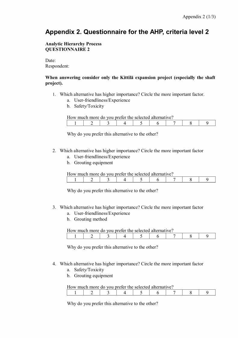
Appendix 2 (1/3)
Analytic Hierarchy ProcessQUESTIONNAIRE 2
Date:Respondent:
When answering consider only the Kittilä expansion project (especially the shaftproject).
1. Which alternative has higher importance? Circle the more important factor.a. User-friendliness/Experienceb. Safety/Toxicity
How much more do you prefer the selected alternative?1 2 3 4 5 6 7 8 9
Why do you prefer this alternative to the other?
2. Which alternative has higher importance? Circle the more important factora. User-friendliness/Experienceb. Grouting equipment
How much more do you prefer the selected alternative?1 2 3 4 5 6 7 8 9
Why do you prefer this alternative to the other?
3. Which alternative has higher importance? Circle the more important factora. User-friendliness/Experienceb. Grouting method
How much more do you prefer the selected alternative?1 2 3 4 5 6 7 8 9
Why do you prefer this alternative to the other?
4. Which alternative has higher importance? Circle the more important factora. Safety/Toxicityb. Grouting equipment
How much more do you prefer the selected alternative?1 2 3 4 5 6 7 8 9
Why do you prefer this alternative to the other?

Appendix 2 (2/3)
5. Which alternative has higher importance? Circle the more important factora. Safety/Toxicityb. Grouting method
How much more do you prefer the selected alternative?1 2 3 4 5 6 7 8 9
Why do you prefer this alternative to the other?
6. Which alternative has higher importance? Circle the more important factora. Grouting equipmentb. Grouting method
How much more do you prefer the selected alternative?1 2 3 4 5 6 7 8 9
Why do you prefer this alternative to the other?

Appendix 2 (3/3)
See table below for explanations of the alternatives.Criterion Explanation
User-friendliness/ExperienceThe importance of selecting a user-friendly grout with which thecontractor has experience in grouting i.e. the material is familiar tothe contractor.
Safety/Toxicity The importance of selecting an environmentally safe groutingmaterial, which does not cause health concerns to the human either.
Grouting equipmentThe importance of selecting a grouting material that suits well withthe available grouting equipment and does not need special/newequipment in the grouting.
Grouting method The importance of the grouting method to be suitable with thegrouting material.
See table below to choose the intensity of preference between one alternative to another.Intensity ofimportance Definition Explanation
1 Equal importance Two activities contribute equally to the objective.
3 Moderate importance of one overanother
Experience and judgment slightly favor oneactivity over another.
5 Essential or strong importance Experience and judgment strongly favor oneactivity over another.
7 Very strong importance An activity is strongly favored and its dominancedemonstrated in practice.
9 Extreme importance The evidence favoring one activity over anotheris of the highest possible order of affirmation.
2, 4, 6, 8 Intermediate values between thetwo adjacent judgments When compromise is needed.

Appendix 3 (1/1)
Average 2Grouting material
selection(Goal)
Execution ofgrouting
work
Costs andschedule
Rockconditions
Ground waterproperties and
conditionsw
Execution ofgrouting work 1 2 1/2 2 1.19 0.28
Costs and schedule 1/2 1 1 2 1.00 0.24Rock conditions 2 1 1 2 1.41 0.34
Ground waterproperties and
conditions1/2 1/2 1/2 1 0.59 0.14
SUM 4.00 4.50 3.00 7.00 4.20 1.00max 4.18
CR 0.07
Average 3Grouting material
selection(Goal)
Execution ofgrouting
work
Costs andschedule
Rockconditions
Ground waterproperties and
conditionsw
Execution ofgrouting work 1 1.73 0.53 1.78 1.13 0.27
Costs and schedule 0.58 1 1.12 2.33 1.11 0.26Rock conditions 1.89 0.89 1 2.33 1.41 0.33
Ground waterproperties and
conditions0.56 0.43 0.43 1 0.57 0.13
SUM 4.03 4.05 3.08 7.44 4.21 1.00max 4.16
CR 0.06