copyright © 2017 makerinme technologies private...
TRANSCRIPT

Page 1
Copyright © 2017 MakerInMe Technologies Private Limited
Cretile™ ProLogic is a programmable module. Cretile ProLogic can be programmed with the help of ArduBlocks* or by writing C/C++ code.
With ArduBlocks you can program Cretile ProLogic without having to write code in C or C++. ArduBlocks provides simple drag and drop blocks to build a programming Logic. The ArduBlocks environment looks like below:
ArduBlock* is an open source OpenBlocks* based visual programming environment. It is extended to work with
Cretile ProLogic and can be downloaded from here
If you know how to program in C/C++ language, you can choose to program using these programming languages instead of using ArduBlock.
*Registered third party trademarks brand/product names

Page 2
Copyright © 2017 MakerInMe Technologies Private Limited
Let’s get started
1 First step is to install the ArduBlock
Download ArduBlock from here and run ArduinoCretile.exe file on your Windows based computer/tablet. Current software is supported only for Microsoft Windows* 7 & above computer/tablets. Once installed, Arduino* will appear in your program list of Windows “Start Menu”. On Windows 10, it should look similar to below.
Click on Arduino icon to open the application. Below is how it looks like
Click on ‘Tools’ menu item and Choose ’ArduBlock’ option
*Registered third party trademarks brand/product names

Page 3
Copyright © 2017 MakerInMe Technologies Private Limited
ArduBlock opens up and looks like
below
2
Now setup ArduBlock to work with Cretile ProLogic Choose the Board
a. Open the Arduino b. Use ‘Tools’ menu c. Choose ‘Board’ menu
item d. Select ‘Arduino Nano w/
ATmega 328’ board from the list
Choose the how Cretile ProLogic
will talk to your PC a. Connect Cretile ProLogic
to your computer using a micro-USB cable
b. Open the Arduino Editor c. Use ‘Tools’ menu d. Choose ‘Serial Port menu
item. e. Generally you should see
one of COM port (Communication Port) selected here. In case, there are more than one ports mentioned in this list, you will have to try out each of the ports to check which port works for your setup.

Page 4
Copyright © 2017 MakerInMe Technologies Private Limited
Program #1: Let’s now write the very first Blinking Light Program
1 What you need 1. Cretile Battery or Cretile Power 2. Cretile Light 3. Cretile ProLogic 4. A micro-USB Cable
2
Now make connections as shown
3
Logic that we need to implement
1. Switch ON the Cretile Light 2. Wait for 1 Sec 3. Switch OFF the Cretile Light 4. Wait for 1 Sec 5. Start from Step #1 So, if you carry our step 1, 2, 3 & 4 again and again, you will observe a Cretile Light starts to blink. Cretile light shall remain ON for one second and OFF for the next one second. This is happen indefinitely.
4
Writing ArduBlock Blinking Light Program 1. Open Arduino application. 2. Click on ‘Tools’ menu option&
choose ‘ArduBlock’ option 3. ArduBlock editor opens up as
shown here

Page 5
Copyright © 2017 MakerInMe Technologies Private Limited
From the left side menu items, choose ‘Cretile ProLogic’ option. You will see all Cretile ProLogic function as shown here. Similarly other functions are grouped under various categories of options. Explore each of those.
Drag ‘START ProLogic without remote’ function and drop it in the ‘setup’ slot of the ‘program’ as shown. This step makes Cretile ProLogic ready to perform further tasks. It is like a doctor getting ready by wearing his uniform & gathering all the required equipment for the surgery that needs to be done.
Now drag ‘Write ProgLogic local output’ and drop it in the loop section. This step will send ‘99’ value to Cretile Light connected at Output-1. You can send values from 0 to 99. Zero being lowest and 99 being the highest. With ‘99’ Cretile Light will be switch ON with full brightness. If value ‘50’ used instead of ‘99’, Cretile Light will be switched ON but with 50% brightness. This will complete step #1 of our logic.

Page 6
Copyright © 2017 MakerInMe Technologies Private Limited
Now drag ‘delay SECONDS‘ from ‘Time’ and drop it after ‘WRITE ProLogic’ block. This is the second step of our logic in which we wait for one second. Note that you can also use delay MILLIS milliseconds’ from ‘Time’. In this case you will have to use value 1000 instead of 1. (One second = 1000 milliseconds) This will complete step #2 of our logic
Next drag ‘Write ProgLogic local output’ and drop it after the ‘delay’. Click on the ‘99’ and change it to ‘0’. This will send ‘0’ value to Cretile Light connected at Output-1 making it switch OFF. This will complete step #3 of our logic
Now drag ‘delay SECONDS‘ from ‘Time’ and drop it after ‘WRITE ProLogic’ block. This is fourth step of our logic in which we wait for one second after the Cretile Light is switched OFF
Note that all the four instructions are written inside ’loop’ section of ‘program’. So, when the fourth instruction is completed the loop starts again from the first step. This is how the four step logic will get performed again and again until the circuit switched OFF.

Page 7
Copyright © 2017 MakerInMe Technologies Private Limited
For future use, save the program by using ‘Save’ or ‘Save As’ option from the menu bar and give a suitable name.
Program we just wrote is written on your computer and needs to be sent to Cretile ProLogic. Once sent to Cretile ProLogic the program will start working on Cretile ProLogic immediately. To send the program to Cretile ProLogic click on ‘Upload to Cretile ProLogic. As soon as the program is successfully sent to Cretile ProLogic the program start to execute and you will find that the Cretile Light connected at output-1 starts to blink
You may now remove the USB cable connected between your computer and Cretile ProLogic. The power will be taken from the Cretile Battery and your program will continue to run

Page 8
Copyright © 2017 MakerInMe Technologies Private Limited
Program #2: Control Blinking Speed with Cretile Dimmer
1
What you need
1. Cretile Battery or Cretile Power 2. Cretile Light Cretile 3. Cretile Dimmer 4. Cretile ProLogic 5. A micro-USB Cable
2
Now make connection
3
Logic that we need to implement
1. Read Cretile Dimmer Value; let’s call it ‘dVal’ 2. Switch ON the Cretile Light 3. Wait for dVal milliseconds 4. Switch OFF the Cretile Light 5. Wait for dVal milliseconds 6. Start from Step #1 So, if you carry our step 1, 2, 3, 4 & 5 again and again, you will observe a Cretile Light blinking. As you increase the dimmer value the blinking speed reduces. When you decrease the dimmer value the speed of blinking increases.
4
Writing ArduBlock Program Dimmer Controlled Blinking of Light
Page 9
Copyright © 2017 MakerInMe Technologies Private Limited
Cretile ProLogic with Remote Capability
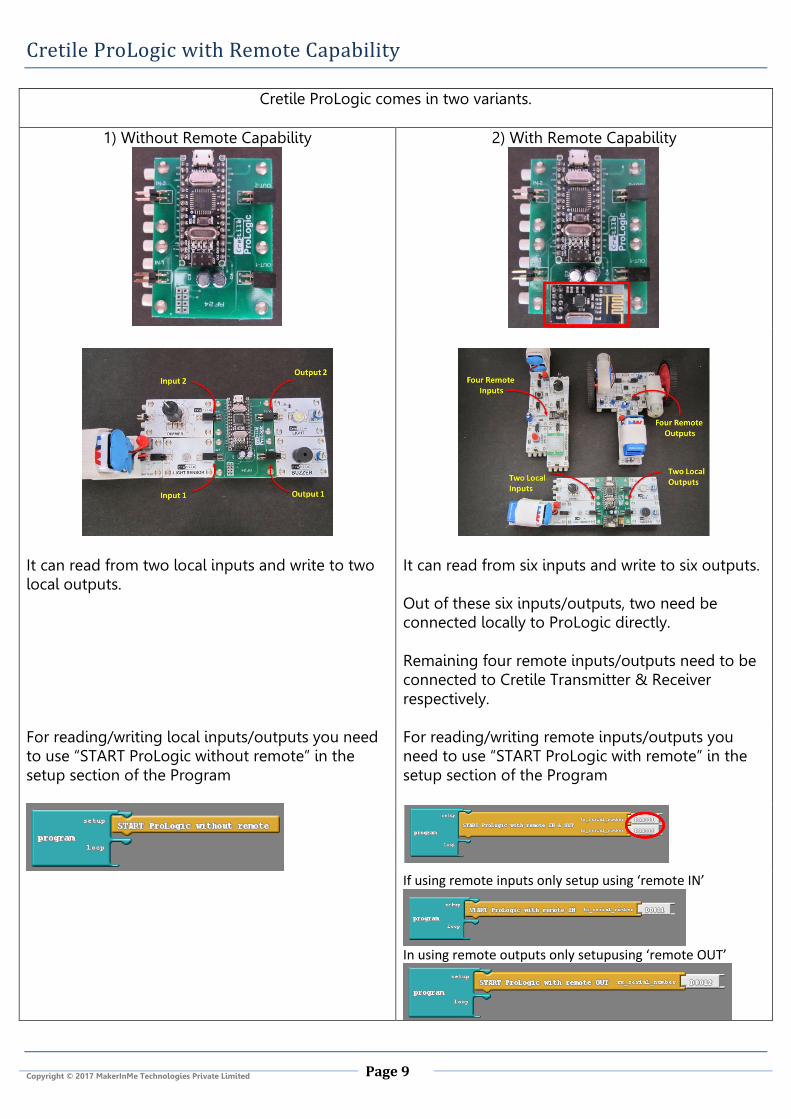
Cretile ProLogic comes in two variants.
1) Without Remote Capability 2) With Remote Capability
It can read from two local inputs and write to two local outputs.
It can read from six inputs and write to six outputs. Out of these six inputs/outputs, two need be connected locally to ProLogic directly. Remaining four remote inputs/outputs need to be connected to Cretile Transmitter & Receiver respectively.
For reading/writing local inputs/outputs you need to use “START ProLogic without remote” in the setup section of the Program
For reading/writing remote inputs/outputs you need to use “START ProLogic with remote” in the setup section of the Program
If using remote inputs only setup using ‘remote IN’
In using remote outputs only setupusing ‘remote OUT’

Page 10
Copyright © 2017 MakerInMe Technologies Private Limited
Program #3: Remotely Control Speed of Blinking Light
GOAL: The goal is to Remotely change speed of Cretile Light blinking 1
What you need
1. Two Cretile Batteries 2. Cretile Receiver 3. Cretile Transmitter 4. Cretile ProLogic 5. Cretile Dimmer 6. Cretile Light 7. A micro-USB Cable
2
Now make the connections
3
Logic that we need to implement The Logic of this program remains the same as that of blink program that we have already written. The Dimmer and Light however are not directly connected to ProLogic. They are remotely connected. 1. Read Cretile Dimmer Value; let’s call it ‘dVal’ 2. Switch ON the Cretile Light 3. Wait for dVal milliseconds 4. Switch OFF the Cretile Light 5. Wait for dVal milliseconds 6. Start from Step #1
So, if you carry our step 1, 2, 3, 4 & 5 again and again, you will observe a Cretile Light blinking. As you increase the dimmer value the blinking speed reduces. When you decrease the dimmer value the speed of blinking increases.
ArduBlock Program to control the vehicle remotely 1
First step is set-up Communication between ProLogic, Receiver & Transmitter Use ‘START ProLogic with remote IN & OUT’ block and put it in ‘setup’ section of ‘Program’
Page 11
Copyright © 2017 MakerInMe Technologies Private Limited
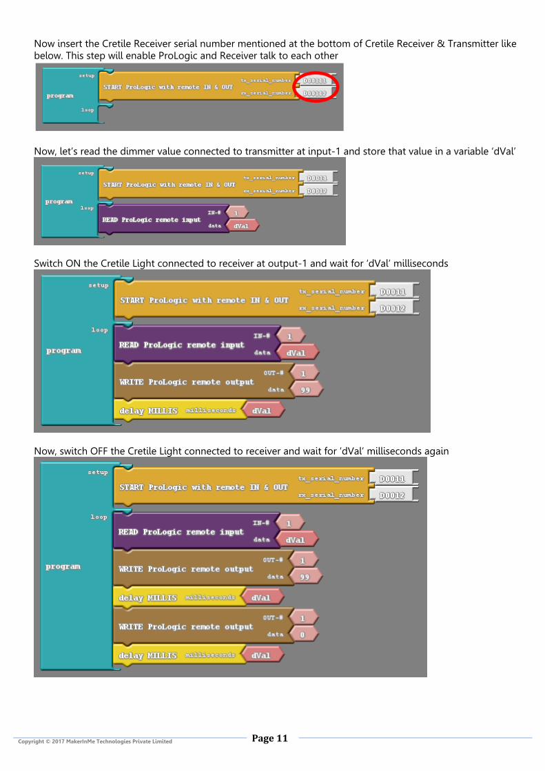
Now insert the Cretile Receiver serial number mentioned at the bottom of Cretile Receiver & Transmitter like below. This step will enable ProLogic and Receiver talk to each other
Now, let’s read the dimmer value connected to transmitter at input-1 and store that value in a variable ‘dVal’
Switch ON the Cretile Light connected to receiver at output-1 and wait for ‘dVal’ milliseconds
Now, switch OFF the Cretile Light connected to receiver and wait for ‘dVal’ milliseconds again

Page 12
Copyright © 2017 MakerInMe Technologies Private Limited
Program #4: Remotely Control a Vehicle Remotely
GOAL: The goal is to move a Vehicle on a rectangular path remotely from a program 1 2
What you need 8. Two Cretile
Batteries 9. Two Cretile Motors 10. Cretile Receiver 11. Cretile ProLogic A micro-USB Cable Now make the connections
3
Logic that we need to implement 1. Start Motor 1 in forward direction 2. Start Motor 2 in reverse direction (Note that two motor when connected to Cretile Receiver is heading in
opposite direction) 3. Wait for some time say three seconds. During these time period the vehicle will move in the forward
direction as both motors are moving in one direction. 4. Now for vehicle to take turn, change the direction of one of the motors 5. Wait for some time say one second. During this time period the vehicle will take a turn as the two motors
are moving in opposite direction. 6. Start over with step 1
So, if you carry our step 1 to 5 again and again, you will observe that vehicle made with Cretiles will move forward for three second and take turn. This will continue indefinitely. By adjusting the time of turn you can make the car to move in a rectangular path. How to control Cretile Motor Cretile Motor has two inputs: Speed and Direction. If ‘99’ is assigned to speed input, Cretile motor will move at full speed. To reduce the speed this number has to be reduced. Zero will stop the motor fully. If ‘99’ assigned to direction input, it will maintain one direction. Assigning ‘0’ and it will reverse its direction. Connections

Page 13
Copyright © 2017 MakerInMe Technologies Private Limited
ArduBlock Program to control the vehicle remotely 1 First step is set-up Communication between ProLogic & Receiver
Use ‘START ProLogic with remote OUT’ block and put it in ‘setup’ section of ‘Program’
Now insert the Cretile Receiver serial number mentioned at the bottom of Cretile Receiver like below. This step will enable ProLogic and Receiver talk to each other
Now, let’s move the vehicle forward
And finally make the vehicle to take a turn

Page 14
Copyright © 2017 MakerInMe Technologies Private Limited
Blank Page

Page 15
Copyright © 2017 MakerInMe Technologies Private Limited
Troubleshooting Guide
Below are some of the common problems that you may face and their solutions.
1 COM port not found error Reason: This will happen if you have more than one instances of ArduBlock open on your computer. Solution: Close the other instance and again use the option ‘Upload to Cretile ProLogic’ to proceed.
2 Upload to Cretile ProLogic
just keeps waiting Reason: This will happen if you have chosen wrong serial port Solution: Chose a different serial port from the Tools->Serial Port menu and again try to ‘Upload to Cretile ProLogic’
3 COM port already in use error Reason: This will happen if you have chosen wrong serial port Solution: Chose a different serial port from the ‘Tools->Serial Port’ menu and again try to ‘Upload to Cretile ProLogic’

Page 16
Copyright © 2017 MakerInMe Technologies Private Limited
Blank Page

Page 17
Copyright © 2017 MakerInMe Technologies Private Limited
Thank you for purchasing Cretile. Please read the instruction manual carefully before using the product. Please ensure that the product is used under adult supervision.
BASIC INSTRUCTIONS
Always assemble or de-assemble Cretiles in power-off mode
Always ensure that the product is used under adult supervision and not left unattended.
Always ensure that the circuit does not come in contact with any metal objects or liquids.
Always ensure that the product is utilized along with a high quality ISI/ISO certified 9V 2A adapter with a compatible DC PIN for the power jack in Power module.
Always ensure that the product is utilized with two 9V PP3 battery only when using Battery module.
Always ensure that the battery is connected to the correct electrical polarity. Caution should be taken not to short-circuit battery terminals to each other which can damage the product and generate heat that may result in burns.
Always take maximum precaution while plugging in batteries so that they are not connection to any wrong electrical polarity. Wrong electrical polarity can cause fire or burns.
Always ensure that the product is used within 0 (zero) to 50 (fifty) degree temperature range only. Exposure to direct sunlight should be avoided.
Never recharge a non-rechargeable battery.
IMPORTANT: PLEASE READ CAREFULLY
Please ensure that you have read and complied with all the details provided on the brochure/instruction manual placed. Please ensure safe and supervised usage of the entire product. In the event that any of the components of the product are dropped, the product may not function as desired. We do not make any express or implied warranties of any kind with respect to the product and we expressly disclaim any warranties of merchantability or fitness for a particular purpose. By using this product, you acknowledge and understand that the battery and the adapter provided separately have not been manufactured by us and we shall in no event be held liable for any loss or damage that may arise as a result of the use of such battery and the adapter. Kindly ensure that you have read and complied with all the instructions provided for the use of the battery and the adapter by the manufacturer. We shall not be held responsible for any incidental, indirect, consequential, or special damages that may arise as a result of the use of the product. Your use of the product implies your acceptance of these terms. If there are any defects or defaults in the product, kindly contact [email protected] within 10 (ten) days from the date of purchase of the product and the same would be replaced.
Any dispute which may arise as a result of the use of this product shall be subject to the jurisdiction of the Courts situated in Bangalore.
Kindly keep the instruction manual and package for reference as they contain important information.
A Product of
www.MakerInMe.com