copyright 2008-2014 kenneth m. chipps ph.d. cisco ccna exploration ccna 2 routing protocols and...
TRANSCRIPT
Copyright 2008-2014 Kenneth M. Chipps Ph.D. www.chipps.com
Cisco CCNA ExplorationCCNA 2
Routing Protocols and ConceptsChapter 1
Introduction to Routing and Packet ForwardingLast Update 2014.01.30
1.9.0
1

Objectives
• Learn what routers do and how they do it
Copyright 2008-2014 Kenneth M. Chipps Ph.D. www.chipps.com
2

A Computer as a Router
• A router is just a special purpose computer• Indeed the first router called an IMP –
Interface Message Processor was a minicomputer
• This first router was used in the first non-proprietary network of networks called APRANET
Copyright 2008-2014 Kenneth M. Chipps Ph.D. www.chipps.com
3

Copyright 2008-2014 Kenneth M. Chipps Ph.D. www.chipps.com
4
Development of Routers
• To see how the need for a device such as a router developed we must look at how ARPANET developed into the Internet
• The original concept of the ARPANET was for a relatively few computers to be connected to a single network
• This slowly changed as it grew into a collection of multiple, independent networks joined together

Copyright 2008-2014 Kenneth M. Chipps Ph.D. www.chipps.com
5
Development of Routers
• This produced the question of how to ensure that computers attached to different networks, and running on different platforms, would be able to communicate with each other
• The main protocol originally used was NCP - Network Control Protocol
• This protocol did not have the ability to handle this function
Copyright 2008-2014 Kenneth M. Chipps Ph.D. www.chipps.com
6
Development of Routers
• One option was to modify the NCP• The design of NCP as more of a device
driver than a true protocol made this difficult
• So, it was decided to develop a new protocol stack, TCP/IP
• It was also seen that additional functionality outside of just software would be needed

Copyright 2008-2014 Kenneth M. Chipps Ph.D. www.chipps.com
7
Development of Routers
• Four ground rules for these functions were specified– Any network should be able to connect to the
Internet without making internal changes– If a packet fails to reach its destination, it will
be retransmitted by the source– No global control should exist at the
operational level– The independent networks will be connected
by black boxes

Development of Routers
• These black boxes became routers
Copyright 2008-2014 Kenneth M. Chipps Ph.D. www.chipps.com
8

What Does a Router Look Like
Copyright 2008-2014 Kenneth M. Chipps Ph.D. www.chipps.com
9

Copyright 2008-2014 Kenneth M. Chipps Ph.D. www.chipps.com
10
This is a Router

Copyright 2008-2014 Kenneth M. Chipps Ph.D. www.chipps.com
11
What Does a Router Look Like
• You may be thinking, this is not a router, this is an old telephone switchboard
• Well it is, but it illustrates exactly what a router does
• So, what does a router do

Copyright 2008-2014 Kenneth M. Chipps Ph.D. www.chipps.com
12
What Does a Router Do
• A router is a simple device• It does exactly what a telephone
switchboard operator does– Path Determination– and– Switching
• For example

Copyright 2008-2014 Kenneth M. Chipps Ph.D. www.chipps.com
13
Doing Path Determination

Copyright 2008-2014 Kenneth M. Chipps Ph.D. www.chipps.com
14
Doing Path Determination
• The preceding is a perfect picture of path determination
• You can see it in the look on the router’s face – I mean the telephone operator’s face
• Someone has called in and said, “Get me New York” or some such place
• The router I mean operator is thinking, ok to connect this call I need to take the cable in my right hand and plug it into …

Copyright 2008-2014 Kenneth M. Chipps Ph.D. www.chipps.com
15
Doing Switching
Copyright 2008-2014 Kenneth M. Chipps Ph.D. www.chipps.com
16
Doing Switching
• How does a router do switching, in other words complete the call
• By plugging the wire into the correct hole or by sending the packet out the correct interface
• Just like the preceding photograph showed

Copyright 2008-2014 Kenneth M. Chipps Ph.D. www.chipps.com
17
What Does a Router Do
• These photographs showing a switchboard operator at an old style telephone switchboard illustrate the operation of a router perfectly
• What is the person doing• A call has come in• The person talking to the operator has
asked to speak to someone

Copyright 2008-2014 Kenneth M. Chipps Ph.D. www.chipps.com
18
What Does a Router Do
• The operator is the intermediary in this transaction
• Based on who the person making the call wants to talk to the operator makes a determination as to which plug on the switchboard the connector must go into to make the connection - path determination
Copyright 2008-2014 Kenneth M. Chipps Ph.D. www.chipps.com
19
What Does a Router Do
• Then the operator completes the circuit by plugging the connector into the switchboard - switching
• This is all there is to it• This is all a router does• What complicates the picture, just as what
complicates the human operator above, is how the routing table is built and maintained, which we will discuss later

Copyright 2008-2014 Kenneth M. Chipps Ph.D. www.chipps.com
20
Routers and Intersections
• How about another way of looking at what a router does
• A router is like an intersection• Just as an intersection allows you to get
from one street to another, a router allows you to get from one network to another
• Lets look at an example

Copyright 2008-2014 Kenneth M. Chipps Ph.D. www.chipps.com
21
Routers and Intersections
INTERSECTION
DEVRY BUILDING AT 4800 REGENT
REGENT
FREEPORT

Copyright 2008-2014 Kenneth M. Chipps Ph.D. www.chipps.com
22
Routers and Intersections
• In this example the building we are in is located at 4800 Regent
• This means the street is Regent and the building number on that street is 4800
• In the city of Irving there can only be one street named Regent
• But there could be many buildings with the 4800 number

Copyright 2008-2014 Kenneth M. Chipps Ph.D. www.chipps.com
23
Routers and Intersections
`
ROUTER
192.168.1.0 NETWORK
10.1.1.0 NETWORK
`
WORKSTATIONON ONE
NETWORK AT BUILDING
NUMBER 23
SERVER ON ANOTHER
NETWORK AT BUILDING NUMBER 3
Copyright 2008-2014 Kenneth M. Chipps Ph.D. www.chipps.com
24
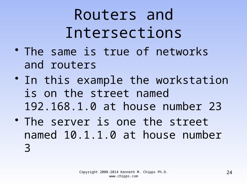
Routers and Intersections
• The same is true of networks and routers• In this example the workstation is on the
street named 192.168.1.0 at house number 23
• The server is one the street named 10.1.1.0 at house number 3
Copyright 2008-2014 Kenneth M. Chipps Ph.D. www.chipps.com
25
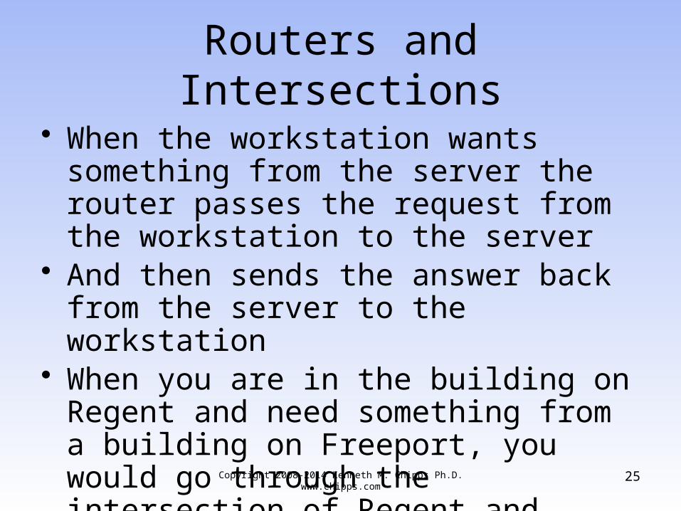
Routers and Intersections
• When the workstation wants something from the server the router passes the request from the workstation to the server
• And then sends the answer back from the server to the workstation
• When you are in the building on Regent and need something from a building on Freeport, you would go through the intersection of Regent and Freeport

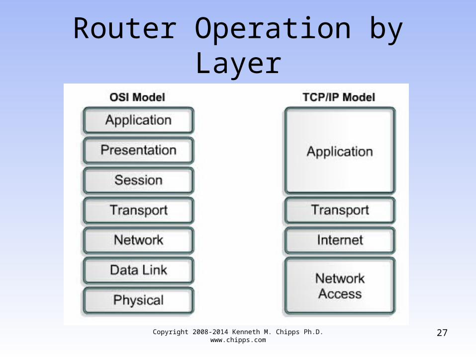
Router Operation by Layer
• Recall that the OSI model is made-up of seven layers and the commonly used TCP/IP routed protocol is made-up of four layers
• In both cases the bottom layers are the same
• These layers are
Copyright 2008-2014 Kenneth M. Chipps Ph.D. www.chipps.com
26
Router Operation by Layer
Copyright 2008-2014 Kenneth M. Chipps Ph.D. www.chipps.com
27

Router Operation by Layer
• A router operates at the bottom layers as it does its two functions of– Path Determination– Switching
• The first step in router operation occurs at layer 3 in the OSI model called the Internet or Network Layer in the TCP/IP model
• This is where the router determines in which network a packet belongs
Copyright 2008-2014 Kenneth M. Chipps Ph.D. www.chipps.com
28

Router Operation by Layer
• Based on this determination at layer 2 in the OSI model the Data Link layer the packet is changed to a frame in whatever format is required for the type of connection that is used at the Physical layer
• At the Physical layer or layer 1 in the OSI model the frame is switched out of the router onto a link for it to exit the router
Copyright 2008-2014 Kenneth M. Chipps Ph.D. www.chipps.com
29
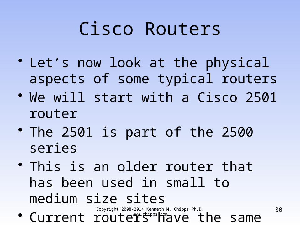
Cisco Routers
• Let’s now look at the physical aspects of some typical routers
• We will start with a Cisco 2501 router• The 2501 is part of the 2500 series• This is an older router that has been used
in small to medium size sites• Current routers have the same
characteristics
Copyright 2008-2014 Kenneth M. Chipps Ph.D. www.chipps.com
30
Copyright 2008-2014 Kenneth M. Chipps Ph.D. www.chipps.com
31
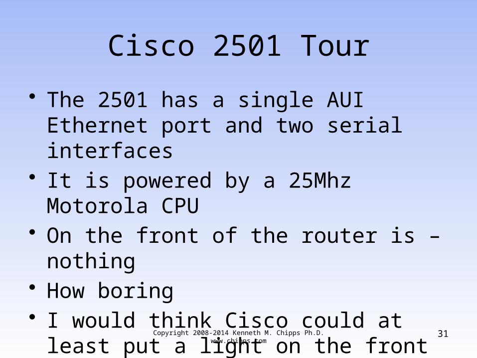
Cisco 2501 Tour
• The 2501 has a single AUI Ethernet port and two serial interfaces
• It is powered by a 25Mhz Motorola CPU• On the front of the router is – nothing• How boring• I would think Cisco could at least put a
light on the front to blink and keep us amused

Copyright 2008-2014 Kenneth M. Chipps Ph.D. www.chipps.com
32
Cisco 2501 Front
Copyright 2008-2014 Kenneth M. Chipps Ph.D. www.chipps.com
33
Cisco 2501 Tour
• At least the back is a little more interesting
Copyright 2008-2014 Kenneth M. Chipps Ph.D. www.chipps.com
34
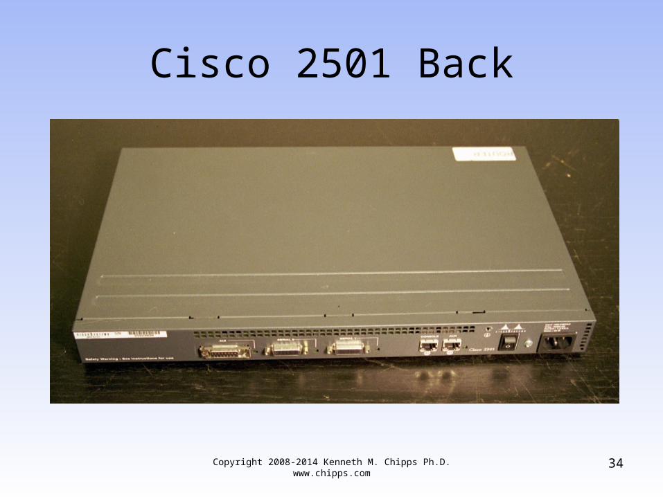
Cisco 2501 Back

Copyright 2008-2014 Kenneth M. Chipps Ph.D. www.chipps.com
35
Cisco 2501 Back
• On the back of the router, in the case of the 2501 we have– Ethernet AUI port– Serial port number 0– Serial port number 1– Console port– Auxiliary port– Power switch– Plug for the power cord

Copyright 2008-2014 Kenneth M. Chipps Ph.D. www.chipps.com
36
Cisco 2501 Back
EthernetPort
SerialPort
SerialPort
ActivityLight
ActivityLight
ActivityLight

Copyright 2008-2014 Kenneth M. Chipps Ph.D. www.chipps.com
37
Cisco 2501 Back
HardwareFailureLight
AuxiliaryPort
PowerSwitch
Power Cord Plug
ConsolePort

Copyright 2008-2014 Kenneth M. Chipps Ph.D. www.chipps.com
38
Cisco 2501 Back
• On the back we have at least a few lights• Next to the Ethernet and serial ports is an
activity light for each one• Next to the Auxiliary Port is a hardware
failure light• If this light does not come on when the
router is powered up, the router has a bad memory card or chip most likely

Copyright 2008-2014 Kenneth M. Chipps Ph.D. www.chipps.com
39
Cisco 2501 Back
• The Ethernet port is an AUI style• This was designed for a 10Base5 network• No one has used such a network in twenty
years• Why Cisco has used this port for so long is
beyond me

Copyright 2008-2014 Kenneth M. Chipps Ph.D. www.chipps.com
40
Cisco 2501 Back
• To actually use this port a transceiver will have to be attached to it to convert the port to an RJ-45 connector as is used in the real world
• This is the device shown next

Copyright 2008-2014 Kenneth M. Chipps Ph.D. www.chipps.com
41
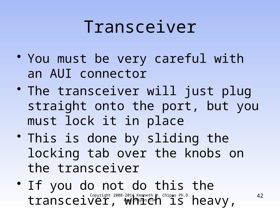
Transceiver
Copyright 2008-2014 Kenneth M. Chipps Ph.D. www.chipps.com
42
Transceiver
• You must be very careful with an AUI connector
• The transceiver will just plug straight onto the port, but you must lock it in place
• This is done by sliding the locking tab over the knobs on the transceiver
• If you do not do this the transceiver, which is heavy, may come loose

Copyright 2008-2014 Kenneth M. Chipps Ph.D. www.chipps.com
43
AUI Interface Locking Tab
Locking tab

Copyright 2008-2014 Kenneth M. Chipps Ph.D. www.chipps.com
44
Transceiver
• Fortunately the newer routers use a standard RJ-45 connector

Copyright 2008-2014 Kenneth M. Chipps Ph.D. www.chipps.com
45
Serial Ports
• The next two ports over are used for the serial – WAN connections
• In the case of a 2501 router these are high-density 60-pin connectors
• This is where the V.35 cable attaches as it comes over from the CSU/DSU
• These connectors are called fixed interface connectors because they are attached directly to the router motherboard

Copyright 2008-2014 Kenneth M. Chipps Ph.D. www.chipps.com
46
Serial Ports
• In the newer style routers these are modular interfaces
• These plug into a bus on the motherboard• As such they may be changed for others• For example

Copyright 2008-2014 Kenneth M. Chipps Ph.D. www.chipps.com
47
T Carrier Modular Interface

Copyright 2008-2014 Kenneth M. Chipps Ph.D. www.chipps.com
48
ISDN Modular Interface

Copyright 2008-2014 Kenneth M. Chipps Ph.D. www.chipps.com
49
Cisco Modular Interface

Copyright 2008-2014 Kenneth M. Chipps Ph.D. www.chipps.com
50
2600 Module Cover

Copyright 2008-2014 Kenneth M. Chipps Ph.D. www.chipps.com
51
2600 Module Slot Open

2600 External Connections
Copyright 2008-2014 Kenneth M. Chipps Ph.D. www.chipps.com
52

Copyright 2008-2014 Kenneth M. Chipps Ph.D. www.chipps.com
53
External Router Connections

Copyright 2008-2014 Kenneth M. Chipps Ph.D. www.chipps.com
54
More Serial Ports
• When two serial ports are not enough a larger router is called for
• In this case a Cisco 7000 is shown• The serial ports are on a slide-in board
called a blade• As more ports are needed, another blade
is put into the 7000’s chassis

Copyright 2008-2014 Kenneth M. Chipps Ph.D. www.chipps.com
55
Cisco 7000

Copyright 2008-2014 Kenneth M. Chipps Ph.D. www.chipps.com
56
Cisco 7000 Multiple Ports

Copyright 2008-2014 Kenneth M. Chipps Ph.D. www.chipps.com
57
Cisco 7000 Multiple Ports

Copyright 2008-2014 Kenneth M. Chipps Ph.D. www.chipps.com
58
Router Interfaces
• When buying a router be sure to specify the correct interface based on the type of access line that will be used
• In other words, an ISDN line cannot connect to an interface designed for a T Carrier line
• Although a Frame Relay line can use the T Carrier interface, since Frame Relay is provided over a T Carrier line usually

Copyright 2008-2014 Kenneth M. Chipps Ph.D. www.chipps.com
59
Router Interfaces
• This is easier to do with the newer model routers that use the modular interfaces
• These newer model routers just have slots as shown above
• Any access line interface – that the manufacturer makes – can be plugged in
• If the line is changed, there is no need to change the entire router

Copyright 2008-2014 Kenneth M. Chipps Ph.D. www.chipps.com
60
Router Interfaces
• The point is to be sure everything will connect properly to everything else being used
Lab
• Start Packet Tracer• Do Packet Tracer Activity 1.1.5.3
Copyright 2008-2014 Kenneth M. Chipps Ph.D. www.chipps.com
61

Lab
• Start Packet Tracer• Do Packet Tracer Activity 1.1.5.4
Copyright 2008-2014 Kenneth M. Chipps Ph.D. www.chipps.com
62
Copyright 2008-2014 Kenneth M. Chipps Ph.D. www.chipps.com
63
Inside the Box
• The only thing inside the router is a single circuit board
• The only thing that can be done here is to add or change the memory or ROM chips

Copyright 2008-2014 Kenneth M. Chipps Ph.D. www.chipps.com
64
Inside the Box

Copyright 2008-2014 Kenneth M. Chipps Ph.D. www.chipps.com
65
Router Internal Components

Copyright 2008-2014 Kenneth M. Chipps Ph.D. www.chipps.com
66
Router Internal Components

Copyright 2008-2014 Kenneth M. Chipps Ph.D. www.chipps.com
67
2600 Internal Components

Copyright 2008-2014 Kenneth M. Chipps Ph.D. www.chipps.com
68
The Cisco IOS
• The Cisco IOS in all its forms is the main asset of Cisco
• The hardware upon which the various IOSs run are fairly unremarkable
• What makes Cisco the market leader in many segments of the market is the quality and scope of the IOS
Copyright 2008-2014 Kenneth M. Chipps Ph.D. www.chipps.com
69
Forms of the Cisco IOS
• The Cisco IOS is used in– Switches– Routers– Firewalls– Wireless Access Points– and so on
• Each version is specific to its use

Copyright 2008-2014 Kenneth M. Chipps Ph.D. www.chipps.com
70
Forms of the Cisco IOS
• One of the problems with this is as Cisco buys companies, which they often do to expand market share, the operating system it comes with is different from those developed by Cisco
• An example is the menu driven switch IOS• Over time it has been migrated to the
more common Cisco command line style

IOS Versions
• There are many versions of the Cisco IOS• I will let Wendell Odom explain the
simplified version of this• It is more complicated than this, but here
are the basics
Copyright 2008-2014 Kenneth M. Chipps Ph.D. www.chipps.com
71

IOS Versions
– Cisco produces a legion of IOS images, although over time, they've been reducing the number of different images
– For instance, each model series has a different IOS image
– In fact, inside one model series, they may be more than one image for different subsets of the model series
Copyright 2008-2014 Kenneth M. Chipps Ph.D. www.chipps.com
72

IOS Versions
– To make bug fixes, Cisco fixes the code, compiles the IOS into an image file, gives it a new release number, and posts it
– For every model series that has a different IOS image, and every subset in that series that has a different IOS, Cisco then has to create a new IOS image for that next minor bug fix release
Copyright 2008-2014 Kenneth M. Chipps Ph.D. www.chipps.com
73
IOS Versions
– On top of that, Cisco maintains different major versions of software, as you would expect, so a single bug fix may need to roll out into multiple major versions - all of which means different IOS images are recompiled
– Cisco also produces different trains of IOS, using a suffix on the main version number to identify the train
Copyright 2008-2014 Kenneth M. Chipps Ph.D. www.chipps.com
74
IOS Versions
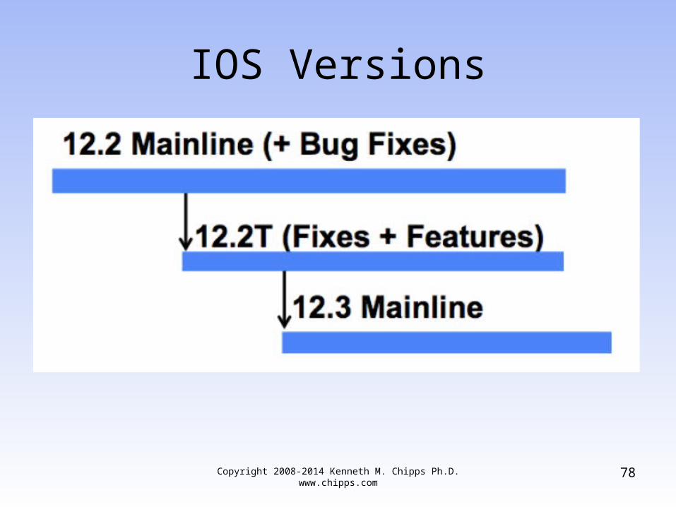
– A train is a series of IOS images that Cisco updates either with an eye towards safety, adding new features (which isn't as safe), or some compromise between the two
– Some trains are build to reduce risk, at the expense of adding less features; some have more features, but at the risk that those features cause other problems
– For example, 12.2, with no suffix, is the core train, called "mainline“
Copyright 2008-2014 Kenneth M. Chipps Ph.D. www.chipps.com
75
IOS Versions
– It is the most stable train, with no new features added
– The T-train, named 12.2T, has the same bug fixes as 12.2 mainline, plus some new features when Cisco completes them, so it's potentially less stable, but it may give you a feature you need
Copyright 2008-2014 Kenneth M. Chipps Ph.D. www.chipps.com
76
IOS Versions
– Other suffixes identify other trains, sometimes with newer features that are riskier, sometimes with newer features meant for a particular market
• Here is a chart on this
Copyright 2008-2014 Kenneth M. Chipps Ph.D. www.chipps.com
77
IOS Versions
Copyright 2008-2014 Kenneth M. Chipps Ph.D. www.chipps.com
78

IOS Versions
• In addition to the version numbers each one has one or more feature sets
Copyright 2008-2014 Kenneth M. Chipps Ph.D. www.chipps.com
79

IOS Versions
• Jessie Pagan in a presentation from the 2011 Cisco Academy Conference titled Cisco Tools, Online Resources and IOS Fundamentals expands on this
• He says
Copyright 2008-2014 Kenneth M. Chipps Ph.D. www.chipps.com
80

IOS Versions
Copyright 2008-2014 Kenneth M. Chipps Ph.D. www.chipps.com
81

IOS Versions
• A Cisco IOS image is a binary executable file of a feature set for a specific platform
• Multiple different images exist of any one release
• The Cisco IOS software image name represents the hardware, feature set, format, and other information about the image file
Copyright 2008-2014 Kenneth M. Chipps Ph.D. www.chipps.com
82

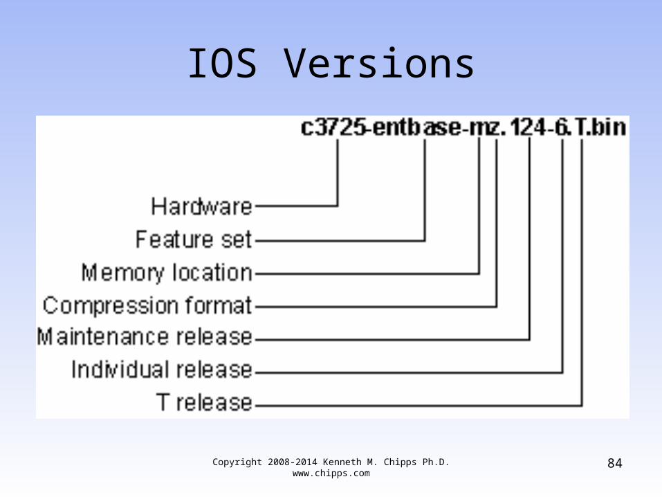
IOS Versions
• The figure below shows the image name of a 12.4(6)T Release with the Enterprise Base feature set for the Cisco 3725
Copyright 2008-2014 Kenneth M. Chipps Ph.D. www.chipps.com
83
IOS Versions
Copyright 2008-2014 Kenneth M. Chipps Ph.D. www.chipps.com
84

IOS Version 15
• Although you will use the 12 version of the Cisco IOS for a long time you need to also know that Cisco has moved on to version 15
• It has several major differences• Kevin Hamilton and Dwight Hughes
discussed version 15 at the 2011 Cisco Academy conference
• They say the first change isCopyright 2008-2014 Kenneth M. Chipps Ph.D.
www.chipps.com85

IOS Version 15
– There is only a single universal IOS image that contains all Cisco IOS features
– A single universal IOS image is shipped with the devices
– The IOS functionality is determined by licenses applied to the devices
Copyright 2008-2014 Kenneth M. Chipps Ph.D. www.chipps.com
86
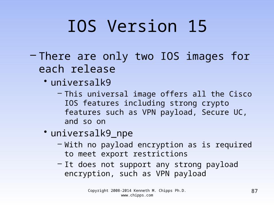
IOS Version 15
– There are only two IOS images for each release• universalk9
– This universal image offers all the Cisco IOS features including strong crypto features such as VPN payload, Secure UC, and so on
• universalk9_npe– With no payload encryption as is required to meet export
restrictions– It does not support any strong payload encryption, such
as VPN payload
Copyright 2008-2014 Kenneth M. Chipps Ph.D. www.chipps.com
87

IOS Version 15
• For example for the 2901 router– c2900-universalk9-mz.SPA.151-4.M.bin– c2900-universalk9_npe-mz.SPA.151.4-M.bin
Copyright 2008-2014 Kenneth M. Chipps Ph.D. www.chipps.com
88

IOS Version 15
• Within each of these images are multiple feature sets
• For example for the 2901 router the feature sets or technology packages are– IP Base– Security– UC– Data
Copyright 2008-2014 Kenneth M. Chipps Ph.D. www.chipps.com
89

IOS Version 15
• The IP Base Technology Package is enabled by default
• Security, UC and Data Technology Package licenses activate more features
Copyright 2008-2014 Kenneth M. Chipps Ph.D. www.chipps.com
90

IOS Version 15
Copyright 2008-2014 Kenneth M. Chipps Ph.D. www.chipps.com
91

IOS Version 15
• Here is the naming scheme for 15
Copyright 2008-2014 Kenneth M. Chipps Ph.D. www.chipps.com
92

IOS Version 15
Copyright 2008-2014 Kenneth M. Chipps Ph.D. www.chipps.com
93

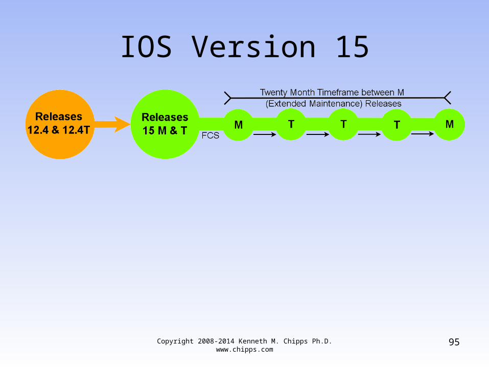
IOS Version 15
• To allow some stability between releases there will be about 20 months between mainline M releases
• So if the new technology added in a T release is not needed, then these Ts can be ignored
Copyright 2008-2014 Kenneth M. Chipps Ph.D. www.chipps.com
94
IOS Version 15
Copyright 2008-2014 Kenneth M. Chipps Ph.D. www.chipps.com
95

IOS 15 Licensing
• Now let’s look at the new licensing method• Here are the main licenses
– Permanent Licenses– Temporary Licenses– Features Licenses
• Software Activation Feature Licenses• Right to Use Feature Licenses
Copyright 2008-2014 Kenneth M. Chipps Ph.D. www.chipps.com
96

Permanent License
• A Permanent License never expires• Once a permanent license is installed on a
router, it is good for that particular feature set for the life of the router even across IOS versions
• A permanent license is the most common license type used when a feature set is purchased for a device
Copyright 2008-2014 Kenneth M. Chipps Ph.D. www.chipps.com
97
Temporary License
• A Temporary License is good for a limited amount of time
• For example an ISR G2 includes a full set of 60 day Temporary Licenses for the Data, UC and Security feature sets
• These can be activated and deactivated at any time to evaluate a feature set before making the decision to convert to a Permanent License
Copyright 2008-2014 Kenneth M. Chipps Ph.D. www.chipps.com
98

Temporary License
• Once a Temporary License expires, it cannot be extended
Copyright 2008-2014 Kenneth M. Chipps Ph.D. www.chipps.com
99

Feature License
• A Feature License typically upgrades to one or more Technology Package licenses
• This can be delivered with new router or upgraded at a later time
• Licenses are enforced through Cisco Software Licensing framework
Copyright 2008-2014 Kenneth M. Chipps Ph.D. www.chipps.com
100

License Management
• There are several ways to manage these licenses including commands and web based tools on the Cisco site
Copyright 2008-2014 Kenneth M. Chipps Ph.D. www.chipps.com
101

Versions 12 and 15
• So the mainstream versions are currently 12 and 15
• What happened to 13 and 14• Cisco is superstitious or at least they think
their customers are• What are they afraid of• Todd Lammle explains it this way in an article
from his website• Part of which is below
Copyright 2008-2014 Kenneth M. Chipps Ph.D. www.chipps.com
102
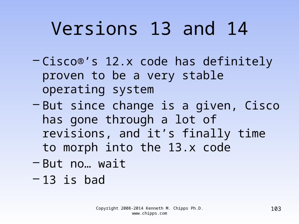
Versions 13 and 14
– Cisco®’s 12.x code has definitely proven to be a very stable operating system
– But since change is a given, Cisco has gone through a lot of revisions, and it’s finally time to morph into the 13.x code
– But no… wait– 13 is bad
Copyright 2008-2014 Kenneth M. Chipps Ph.D. www.chipps.com
103

Versions 13 and 14
– Buildings don’t have a 13th floor, and even if they do, elevators don’t go there!13 is a superstitiously cursed, unlucky number here in the U.S.
– Friday the 13th has been cursed since the 16th Century because that’s the day that the King of France attacked and attempted to jail all of the members of the secretive society, the Knights Templar
Copyright 2008-2014 Kenneth M. Chipps Ph.D. www.chipps.com
104

Versions 13 and 14
– Cisco appears to feel a bit superstitious too… they skipped the 13.x code and went to… 14.x code
– Nope– Not 14 either, because 14 happens to be a
really nasty number in parts of Asia– So to keep anyone from getting the willies,
Cisco jumped to the new 15.x code
Copyright 2008-2014 Kenneth M. Chipps Ph.D. www.chipps.com
105

Versions 13 and 14
– The actual reason for skipping versions 13 and 14 code is of course, nothing but a rumor, but it it’s a fun way to start to this blog
Copyright 2008-2014 Kenneth M. Chipps Ph.D. www.chipps.com
106
Copyright 2008-2014 Kenneth M. Chipps Ph.D. www.chipps.com
107
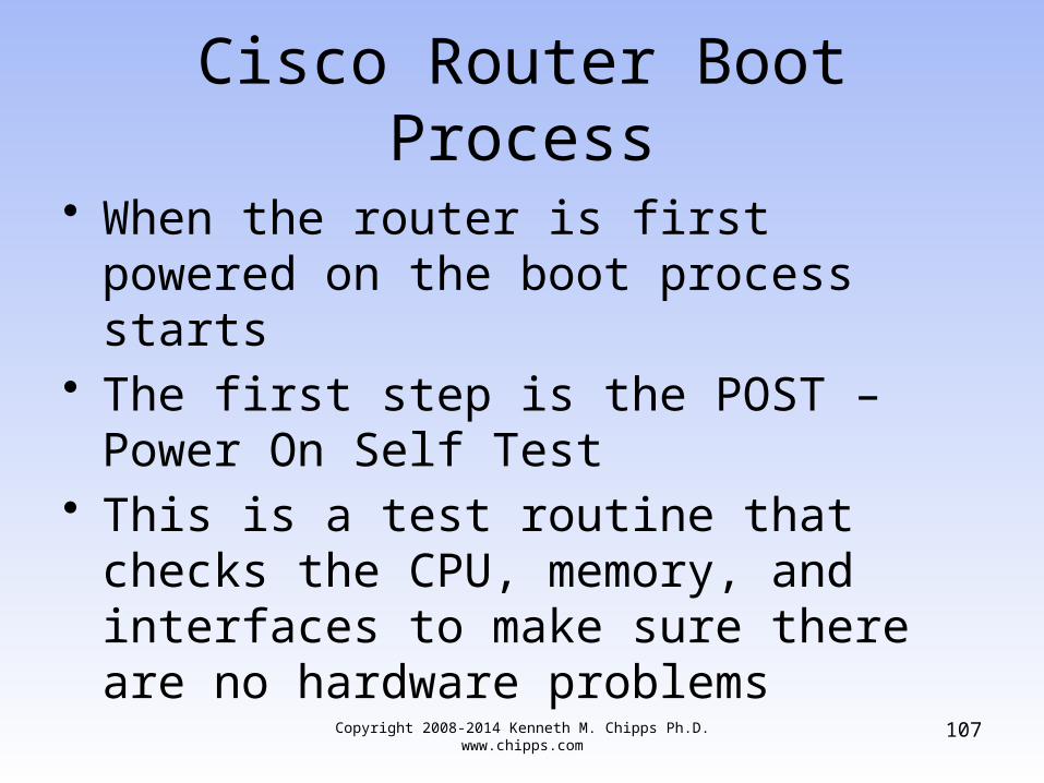
Cisco Router Boot Process
• When the router is first powered on the boot process starts
• The first step is the POST – Power On Self Test
• This is a test routine that checks the CPU, memory, and interfaces to make sure there are no hardware problems
Copyright 2008-2014 Kenneth M. Chipps Ph.D. www.chipps.com
108
Cisco Router Boot Process
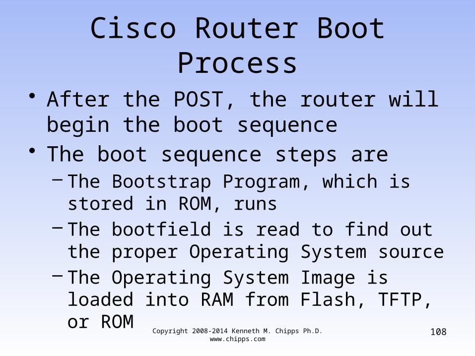
• After the POST, the router will begin the boot sequence
• The boot sequence steps are– The Bootstrap Program, which is stored in
ROM, runs– The bootfield is read to find out the proper
Operating System source– The Operating System Image is loaded into
RAM from Flash, TFTP, or ROM

Copyright 2008-2014 Kenneth M. Chipps Ph.D. www.chipps.com
109
Cisco Router Boot Process
– The Startup Configuration File is read from NVRAM or TFTP server and then loaded into the RAM
– The Configuration File is then executed one line at a time and starts the processes to run the router according to that file
– If no Configuration File is found in NVRAM, the Cisco IOS will offer the chance to use the Initial Configuration Dialog

Copyright 2008-2014 Kenneth M. Chipps Ph.D. www.chipps.com
110
Cisco Router Boot Process
– If the Initial Configuration Dialog is refused, then the router must be configured by hand from the command line
Copyright 2008-2014 Kenneth M. Chipps Ph.D. www.chipps.com
111
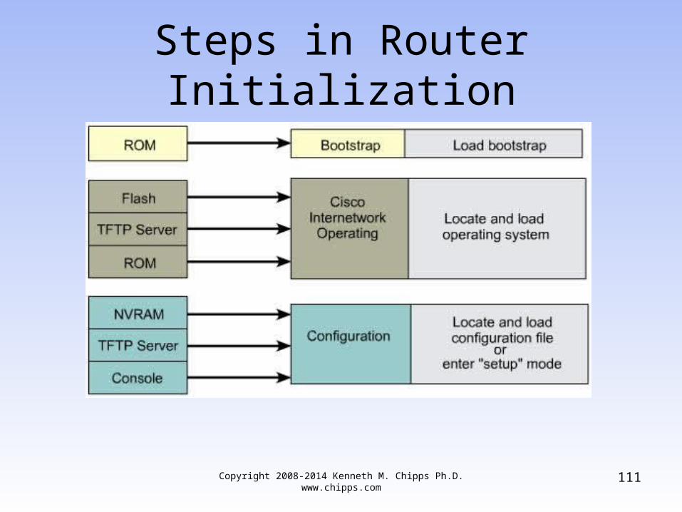
Steps in Router Initialization

Lab
• Let’s see this in action• Start Packet Tracer• Bring a router into the workspace• Double click the router• Select the Config tab• Turn off the router, then turn it back on• Click on the CLI tab to watch the bootup• Select another router and do this again
Copyright 2008-2014 Kenneth M. Chipps Ph.D. www.chipps.com
112

Initial Router Output
• The process of doing the overhead work to make the computer ready to use is called booting, or the boot process, or rebooting the computer
• When booting, the router generates messages about the boot process and sends them out the console port
Copyright 2008-2014 Kenneth M. Chipps Ph.D. www.chipps.com
113

Initial Router Output
• Router output during the boot process– The version of IOS being loaded– The number of interfaces– The types of interfaces– The amount of NVRAM– The amount of flash memory
Copyright 2008-2014 Kenneth M. Chipps Ph.D. www.chipps.com
114

Initial Router Output
Copyright 2008-2014 Kenneth M. Chipps Ph.D. www.chipps.com
115

Router Operation Layers
• A router does its work at layers 1, 2, and 3• For the path determination function the
work is on layer 3• For the switching function the frames
move on layers 1 and 2
Copyright 2008-2014 Kenneth M. Chipps Ph.D. www.chipps.com
116

Routers at Layers 1 2 3
• Routers make decisions at layer 3• But they also carry out functions at layers
1 and 2• At layer 2 the router must create a frame
appropriate for the connection type attached to the interface, such as Ethernet or PPP
• At layer 1 the frame is encoded onto the media
Copyright 2008-2014 Kenneth M. Chipps Ph.D. www.chipps.com
117

Routers at Layers 1 2 3
Copyright 2008-2014 Kenneth M. Chipps Ph.D. www.chipps.com
118

Command Line Interface
• The router’s user interface is called the command-line
• It is not a GUI as Cisco believes the use of the command line is superior to a GUI
• The command line is accessed through a terminal emulator
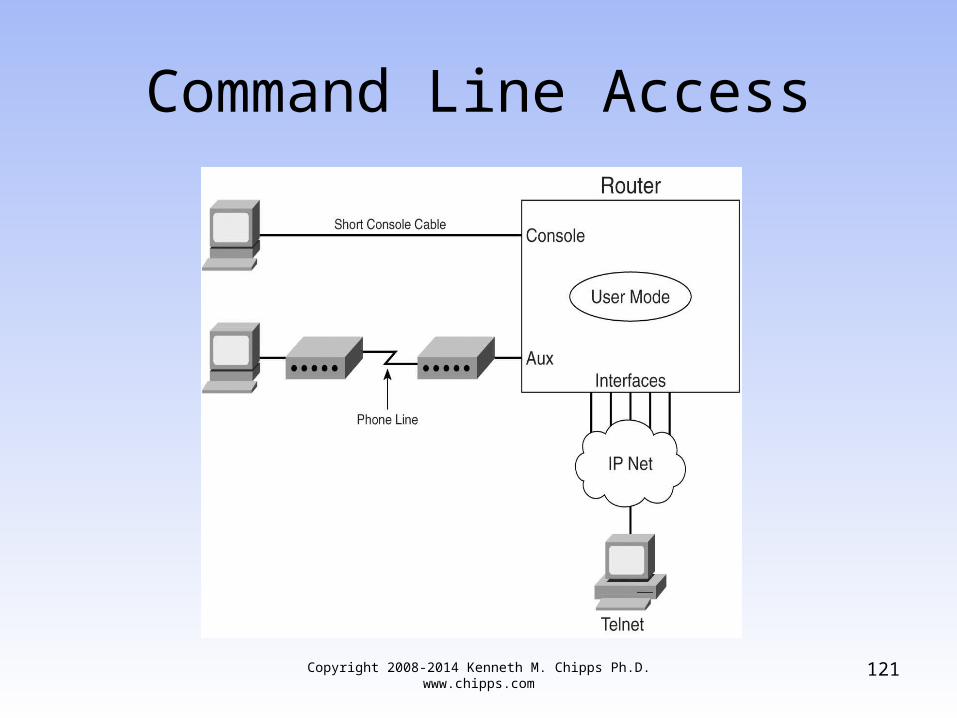
• There are three main methods to reach the command line
Copyright 2008-2014 Kenneth M. Chipps Ph.D. www.chipps.com
119

Command Line Access
• Console Port– Uses the rollover or USB cable to make a
local connection• SSH or Telnet
– Use a data line to make a remote connection • Auxiliary Port
– Uses a modem to make a remote connection
Copyright 2008-2014 Kenneth M. Chipps Ph.D. www.chipps.com
120
Command Line Access
Copyright 2008-2014 Kenneth M. Chipps Ph.D. www.chipps.com
121

Copyright 2008-2014 Kenneth M. Chipps Ph.D. www.chipps.com
122
Console Port
• Some hardware and software is required to configure a Cisco router through the console port
• You must also have direct physical access to the device
• There is an old style and a new style console port
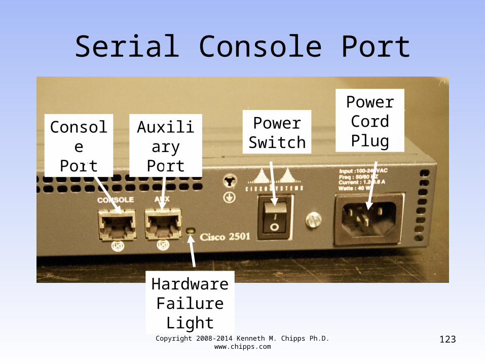
Copyright 2008-2014 Kenneth M. Chipps Ph.D. www.chipps.com
123
Serial Console Port
HardwareFailureLight
AuxiliaryPort
PowerSwitch
Power Cord Plug
ConsolePort

Serial Console Port
• For the serial console port the hardware required includes– Rollover cable
• There are three types of these
– USB to serial port adaptor• If the computer does not have a serial port as is
very common these days a USB must be used
Copyright 2008-2014 Kenneth M. Chipps Ph.D. www.chipps.com
124

Serial Console Port
• A Rollover Cable has the wires on one end reversed in order at the other end
• The newest version is a single cable with the adaptor built as part of it
• The older version of this cable must be used with an adaptor that changes the connection for the serial port from a 9 pin D connector to a RJ-45 jack
Copyright 2008-2014 Kenneth M. Chipps Ph.D. www.chipps.com
125

Copyright 2008-2014 Kenneth M. Chipps Ph.D. www.chipps.com
126
Serial Console Port
• The are also adaptors that will turn a standard patch cable into a rollover cable
• The cable is then attached to this connector with the other end in the Console Port on the back of the router
• Cisco provides the cable with the router

Copyright 2008-2014 Kenneth M. Chipps Ph.D. www.chipps.com
127
Rollover Cable

Copyright 2008-2014 Kenneth M. Chipps Ph.D. www.chipps.com
128
Serial Port Adaptor

Copyright 2008-2014 Kenneth M. Chipps Ph.D. www.chipps.com
129
Rollover Cable and Adaptor

Rollover Cable
Copyright 2008-2014 Kenneth M. Chipps Ph.D. www.chipps.com
130

Rollover Cable Adaptor
Copyright 2008-2014 Kenneth M. Chipps Ph.D. www.chipps.com
131

USB Console Port
• Starting with the G2 hardware version of the ISR – Integrated Services Routers which includes the 1941, 2901, and 2911 routers the console port is now a USB port
• For example
Copyright 2008-2014 Kenneth M. Chipps Ph.D. www.chipps.com
132
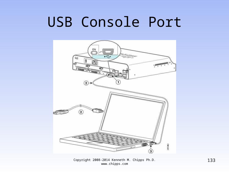
USB Console Port
Copyright 2008-2014 Kenneth M. Chipps Ph.D. www.chipps.com
133
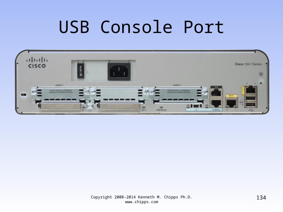
USB Console Port
Copyright 2008-2014 Kenneth M. Chipps Ph.D. www.chipps.com
134

USB Console Port
• You need the USB console driver from Cisco as well
• It only took Cisco about as long as it did to replace the AUI port on the routers to do this
• USB has only been the dominate port on PCs for years
Copyright 2008-2014 Kenneth M. Chipps Ph.D. www.chipps.com
135
Copyright 2008-2014 Kenneth M. Chipps Ph.D. www.chipps.com
136
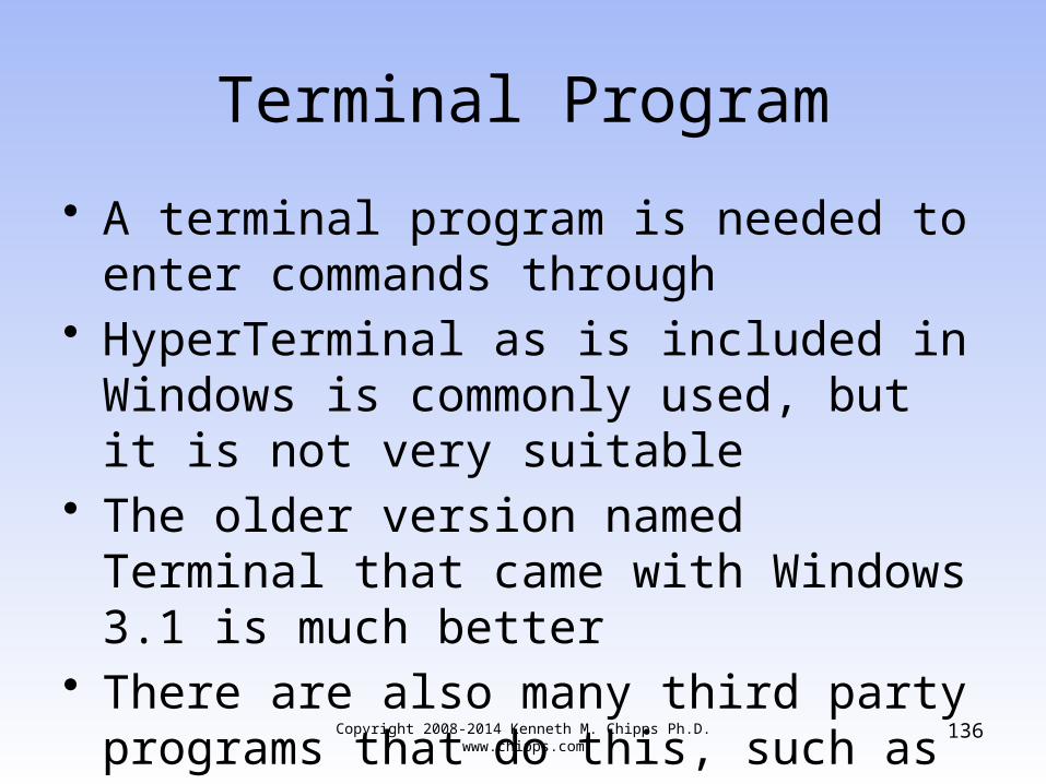
Terminal Program
• A terminal program is needed to enter commands through
• HyperTerminal as is included in Windows is commonly used, but it is not very suitable
• The older version named Terminal that came with Windows 3.1 is much better
• There are also many third party programs that do this, such as Putty

Copyright 2008-2014 Kenneth M. Chipps Ph.D. www.chipps.com
137
Terminal Program
• Set the communications parameters to– 9600 baud– 8 data bits– No parity– 1 stop bits– No flow control
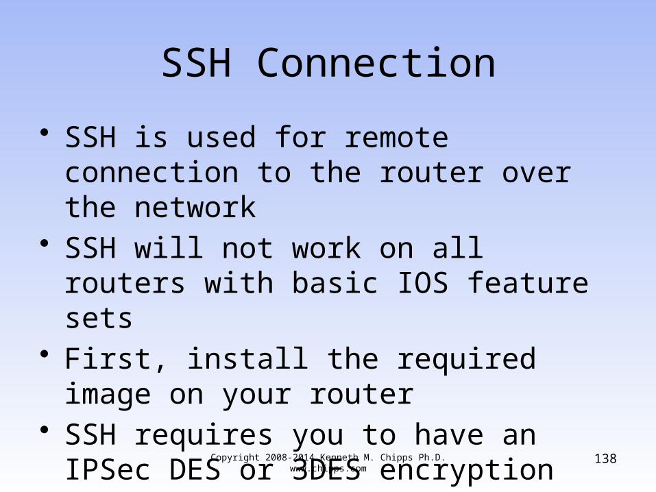
SSH Connection
• SSH is used for remote connection to the router over the network
• SSH will not work on all routers with basic IOS feature sets
• First, install the required image on your router
• SSH requires you to have an IPSec DES or 3DES encryption software image from Cisco IOS Release 12.1(1)
Copyright 2008-2014 Kenneth M. Chipps Ph.D. www.chipps.com
138

SSH Connection
• To configure SSH– Router(config)# hostname hostname – Router(config)# ip domain-name domainname – Router(config)# crypto key generate rsa
• To disable telnet– Router(config)# line vty 0 4– Router(config)# transport input ssh
Copyright 2008-2014 Kenneth M. Chipps Ph.D. www.chipps.com
139

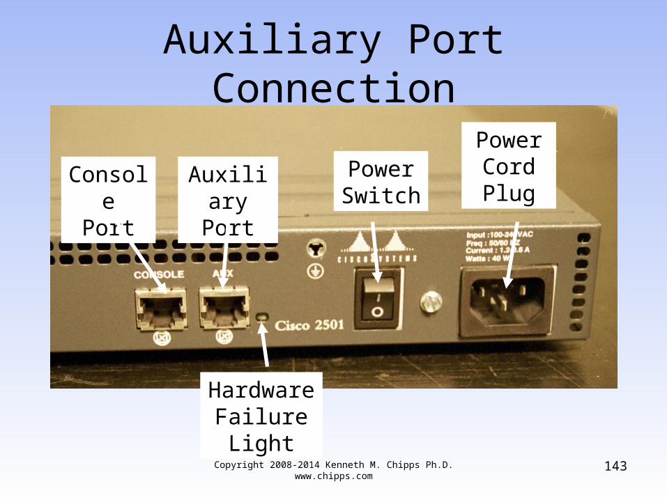
Auxiliary Port Connection
• A connection to a router through the auxiliary port using a modem attached to it is less common these days
• More used is a separate management network of some sort that allows secure remote access
Copyright 2008-2014 Kenneth M. Chipps Ph.D. www.chipps.com
140

Auxiliary Port Connection
• But of course if this network as well as the main network are both down, the onsite access through the console port or remote access through the auxiliary port must be used
Copyright 2008-2014 Kenneth M. Chipps Ph.D. www.chipps.com
141

Auxiliary Port Connection
• To make this type of connection a modem is attached at one end to the auxiliary port and at the other end to a standard PSTN line
Copyright 2008-2014 Kenneth M. Chipps Ph.D. www.chipps.com
142
Copyright 2008-2014 Kenneth M. Chipps Ph.D. www.chipps.com
143
Auxiliary Port Connection
HardwareFailureLight
AuxiliaryPort
PowerSwitch
Power Cord Plug
ConsolePort
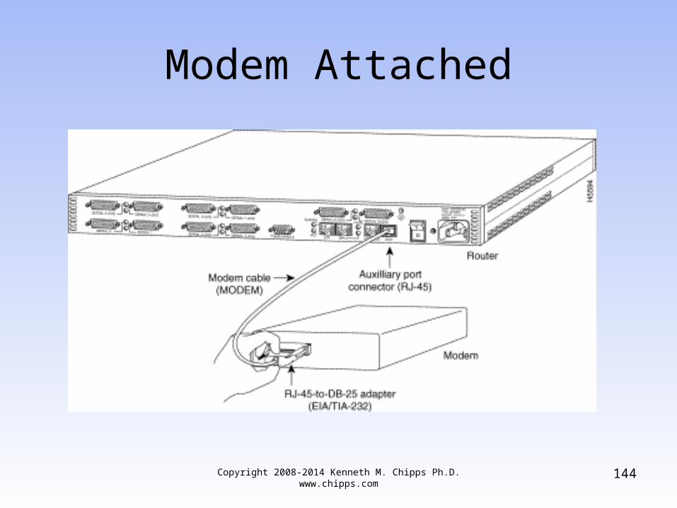
Modem Attached
Copyright 2008-2014 Kenneth M. Chipps Ph.D. www.chipps.com
144

Auxiliary Port Connection
• The configuration on the router is– Router(config)#line 1– Router(config−line)#modem in– Router(config−line)#speed 115200– Router(config−line)#transport input all– Router(config−line)#flowcontrol hardware– Router(config−line)#login– Router(config−line)#password cisco
Copyright 2008-2014 Kenneth M. Chipps Ph.D. www.chipps.com
145
Lab
• Let’s make a console port connection to a router
Copyright 2008-2014 Kenneth M. Chipps Ph.D. www.chipps.com
146

Lab
• Let’s make a telnet connection to a router– Enable telnet by entering
• Router(config)#line vty 0 4• Router(config-line)#login• Router(config-line)#password letmein
– Configure the directly connected interfaces– From a remote router enter
• telnet 192.168.1.2
– or whatever the IP address is of the remote router
Copyright 2008-2014 Kenneth M. Chipps Ph.D. www.chipps.com
147

Copyright 2008-2014 Kenneth M. Chipps Ph.D. www.chipps.com
148
Initial Configuration
• There are three ways to do the initial configuration of a new router or one that has had its configuration wiped out– AutoInstall– System Configuration Dialog– Configuration Mode

Copyright 2008-2014 Kenneth M. Chipps Ph.D. www.chipps.com
149
Auto Install
• The first method of configuring a Cisco router is the Auto Install method
• This process will automatically configure the router after it is connected to the WAN
• This requires that a host on the network be setup to provide the required configuration files

Copyright 2008-2014 Kenneth M. Chipps Ph.D. www.chipps.com
150
Auto Install
• The procedure at the router end is– Attach the WAN cable– Turn on the router– The router will load the IOS from Flash
memory– The AutoInstall process will begin– After the AutoInstall process completes, the
administrator must copy the configuration to NVRAM

Copyright 2008-2014 Kenneth M. Chipps Ph.D. www.chipps.com
151
Auto Install
• With many bootstrap versions if a cable is detected on a WAN port it will attempt the AutoInstall procedure
• The system will spend several minutes determining that no AutoInstall is available
• To avoid this leave the cables unhooked until the IOS load finishes

Copyright 2008-2014 Kenneth M. Chipps Ph.D. www.chipps.com
152
System Configuration Dialog
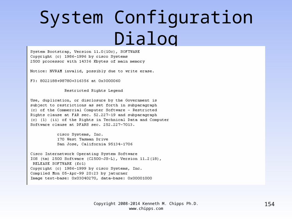
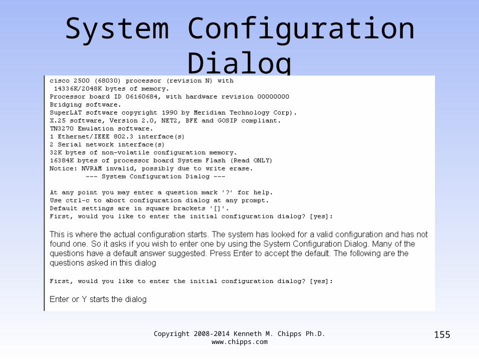
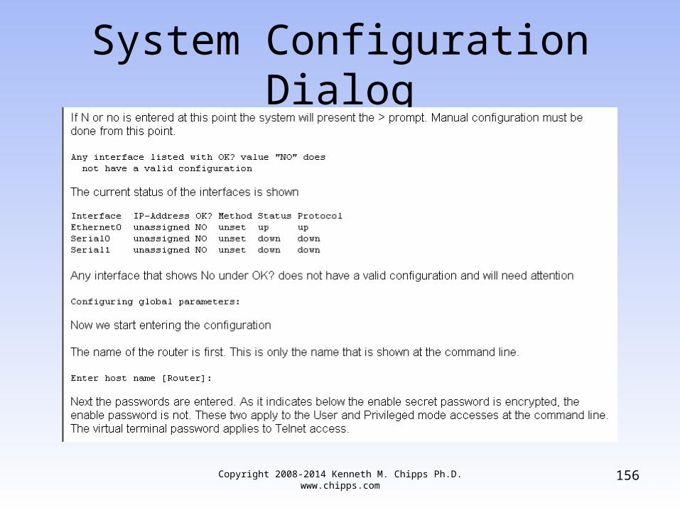
• At bootup when no configuration is found in NVRAM and there is no Auto Install file waiting on some host, the system will ask if it should start the Initial Configuration Dialog, which is also called the System Configuration Dialog
• This is a set of information required by the router for it to function at just a basic level

Copyright 2008-2014 Kenneth M. Chipps Ph.D. www.chipps.com
153
System Configuration Dialog
• In this approach a series of questions are asked by the system
• The user need only supply the answers• When the router is first turned on it
displays the following
Copyright 2008-2014 Kenneth M. Chipps Ph.D. www.chipps.com
154
System Configuration Dialog
Copyright 2008-2014 Kenneth M. Chipps Ph.D. www.chipps.com
155
System Configuration Dialog
Copyright 2008-2014 Kenneth M. Chipps Ph.D. www.chipps.com
156
System Configuration Dialog

Copyright 2008-2014 Kenneth M. Chipps Ph.D. www.chipps.com
157
System Configuration Dialog
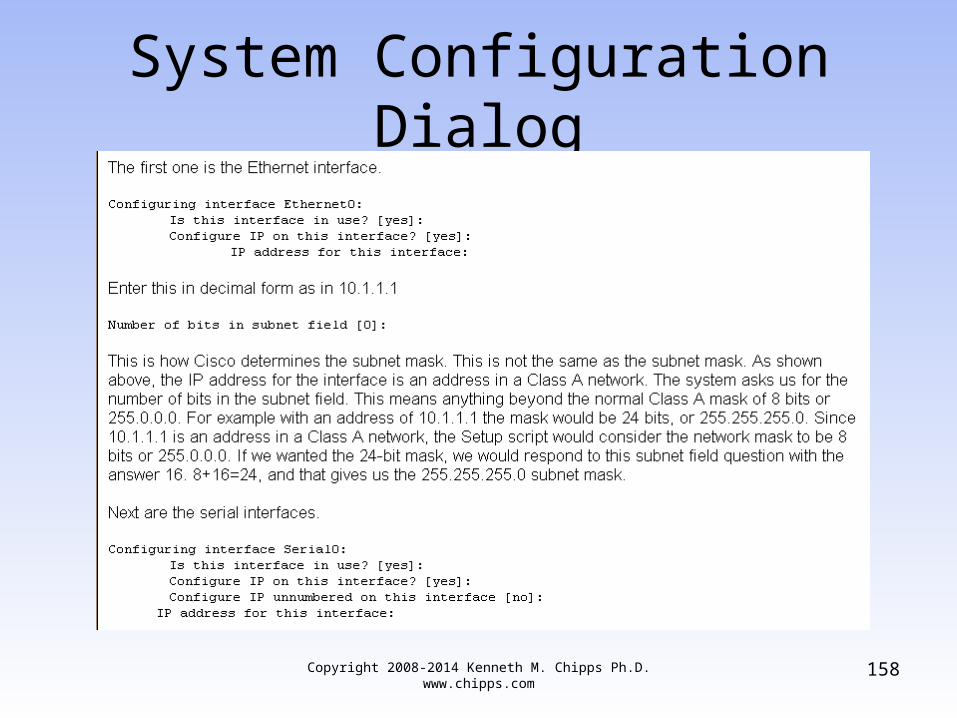
Copyright 2008-2014 Kenneth M. Chipps Ph.D. www.chipps.com
158
System Configuration Dialog

Copyright 2008-2014 Kenneth M. Chipps Ph.D. www.chipps.com
159
System Configuration Dialog
Copyright 2008-2014 Kenneth M. Chipps Ph.D. www.chipps.com
160
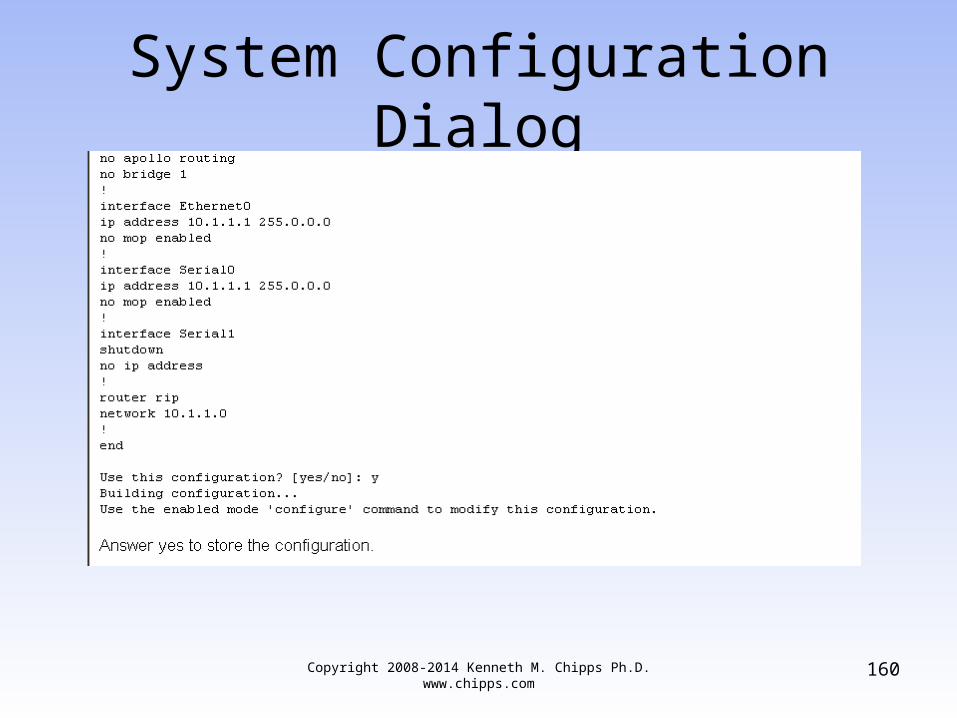
System Configuration Dialog

Copyright 2008-2014 Kenneth M. Chipps Ph.D. www.chipps.com
161
System Configuration Dialog
• This is all there is for basic configuration when it is done using the System Configuration Dialog

Copyright 2008-2014 Kenneth M. Chipps Ph.D. www.chipps.com
162
System Configuration Dialog
Copyright 2008-2014 Kenneth M. Chipps Ph.D. www.chipps.com
163
Command Line Configuration
• The last and most basic method of setting up a Cisco router is to configure it from the command line
• In this method all configuration is done manually from the keyboard
• The keyboard is called the terminal in Cisco talk, just to confuse you

Command Line Configuration
• Enter– config t
• To begin the configuration from the keyboard
Copyright 2008-2014 Kenneth M. Chipps Ph.D. www.chipps.com
164

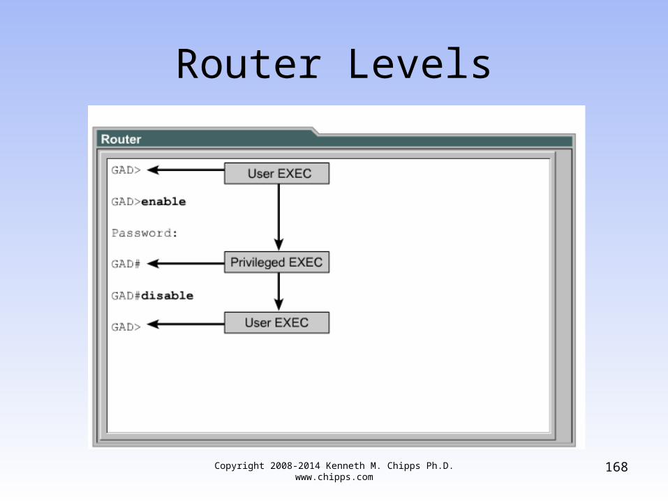
Router Modes
• When the router boots and the IOS loads the IOS stops at a prompt
• At this prompt the router expects the human to do something
• There are two main modes• These are
Copyright 2008-2014 Kenneth M. Chipps Ph.D. www.chipps.com
165

Router Modes
Copyright 2008-2014 Kenneth M. Chipps Ph.D. www.chipps.com
166

Copyright 2008-2014 Kenneth M. Chipps Ph.D. www.chipps.com
167
Router Modes
Copyright 2008-2014 Kenneth M. Chipps Ph.D. www.chipps.com
168
Router Levels

Copyright 2008-2014 Kenneth M. Chipps Ph.D. www.chipps.com
169
Privilege Levels
• At the EXEC level the IOS provides 16 privilege levels ranging from 0 to 15
• Two of these are predefined• User EXEC mode runs at privilege level 1
and enabled mode privileged EXEC mode runs at level 15
• Every IOS command is pre-assigned to either level 1 or level 15
• This assignment can be changed
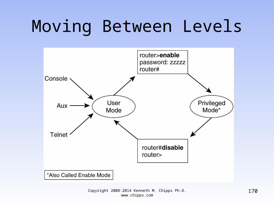
Moving Between Levels
Copyright 2008-2014 Kenneth M. Chipps Ph.D. www.chipps.com
170

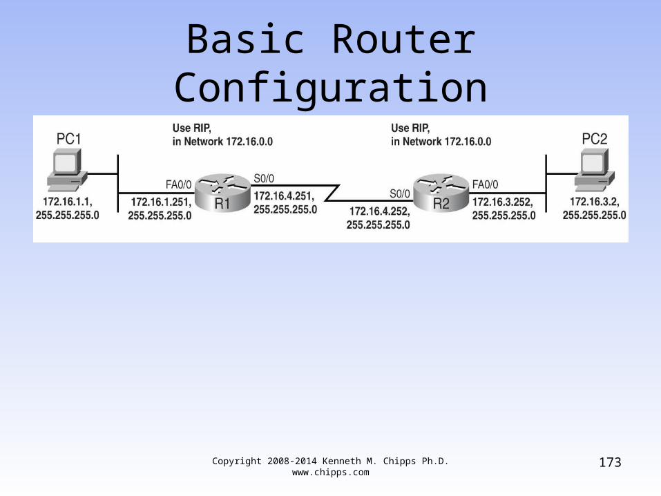
Basic Router Configuration
Copyright 2008-2014 Kenneth M. Chipps Ph.D. www.chipps.com
171
• Basic router configuration is very simple– Plan first
• Decide on the IP addressing scheme to use for the networks that will be connected
• Decide which interfaces will need to be activated to connect those networks
– Next setup the router• Move from user to privileged level• Move to global configuration level• Move to interface configuration level

Basic Router Configuration
Copyright 2008-2014 Kenneth M. Chipps Ph.D. www.chipps.com
172
• Activate the interfaces for the directly connected networks
• Move back to global configuration level• Populate the routing table• Tell the router to put all of this to use
Basic Router Configuration
Copyright 2008-2014 Kenneth M. Chipps Ph.D. www.chipps.com
173

Basic Router Configuration
Copyright 2008-2014 Kenneth M. Chipps Ph.D. www.chipps.com
174

Lab
Copyright 2008-2014 Kenneth M. Chipps Ph.D. www.chipps.com
175
• Start Packet Tracer• Do Packet Tracer Activity 1.2.2.4

The Do Command
Copyright 2008-2014 Kenneth M. Chipps Ph.D. www.chipps.com
176
• If you are running version 12.2(8) or later of the IOS the do command can be used to run privileged level commands in global configuration mode
• For example show run can be issued while entering configuration commands
• Just add do in front of the command• For example
– switch(config-if)#do show run
Copyright 2008-2014 Kenneth M. Chipps Ph.D. www.chipps.com
177
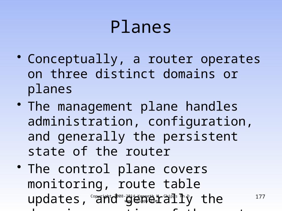
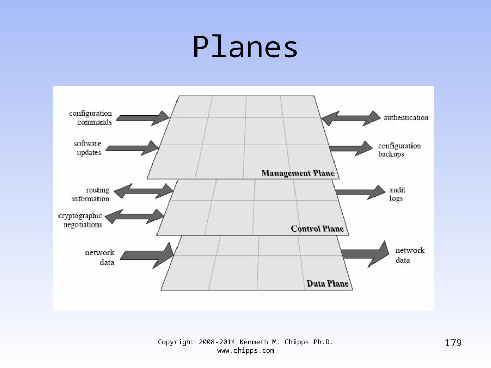
Planes
• Conceptually, a router operates on three distinct domains or planes
• The management plane handles administration, configuration, and generally the persistent state of the router
• The control plane covers monitoring, route table updates, and generally the dynamic operation of the router

Copyright 2008-2014 Kenneth M. Chipps Ph.D. www.chipps.com
178
Planes
• The data or forwarding plane handles the packets transiting the router among the networks it serves
Copyright 2008-2014 Kenneth M. Chipps Ph.D. www.chipps.com
179
Planes

Copyright 2008-2014 Kenneth M. Chipps Ph.D. www.chipps.com
180
Planes
• When traffic is being forwarded from one network to another, it usually does not touch the CPU
• The packets travel across the routing fabric from the incoming interface to the appropriate destination interface
• Only management and control traffic for the router travel to or from the CPU

Copyright 2008-2014 Kenneth M. Chipps Ph.D. www.chipps.com
181
IP Datagram
• The thing that IP uses to carry stuff is the IP datagram
• Like all such devices it has a header and a data area
HEADER DATA

Copyright 2008-2014 Kenneth M. Chipps Ph.D. www.chipps.com
182
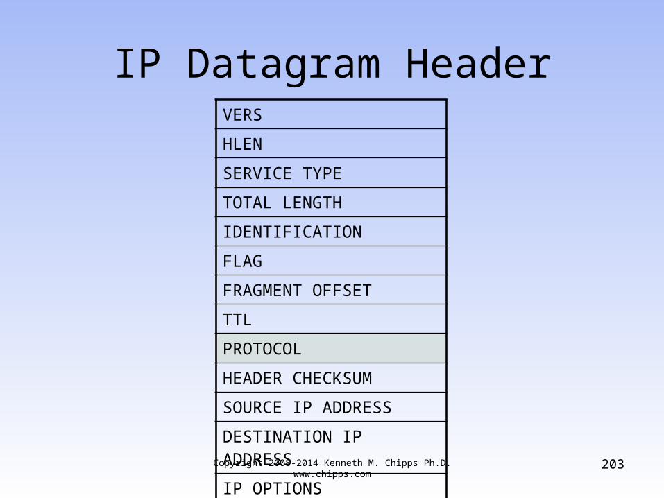
IP Datagram HeaderVERS
HLEN
SERVICE TYPE
TOTAL LENGTH
IDENTIFICATION
FLAG
FRAGMENT OFFSET
TTL
PROTOCOL
HEADER CHECKSUM
SOURCE IP ADDRESS
DESTINATION IP ADDRESS
IP OPTIONS
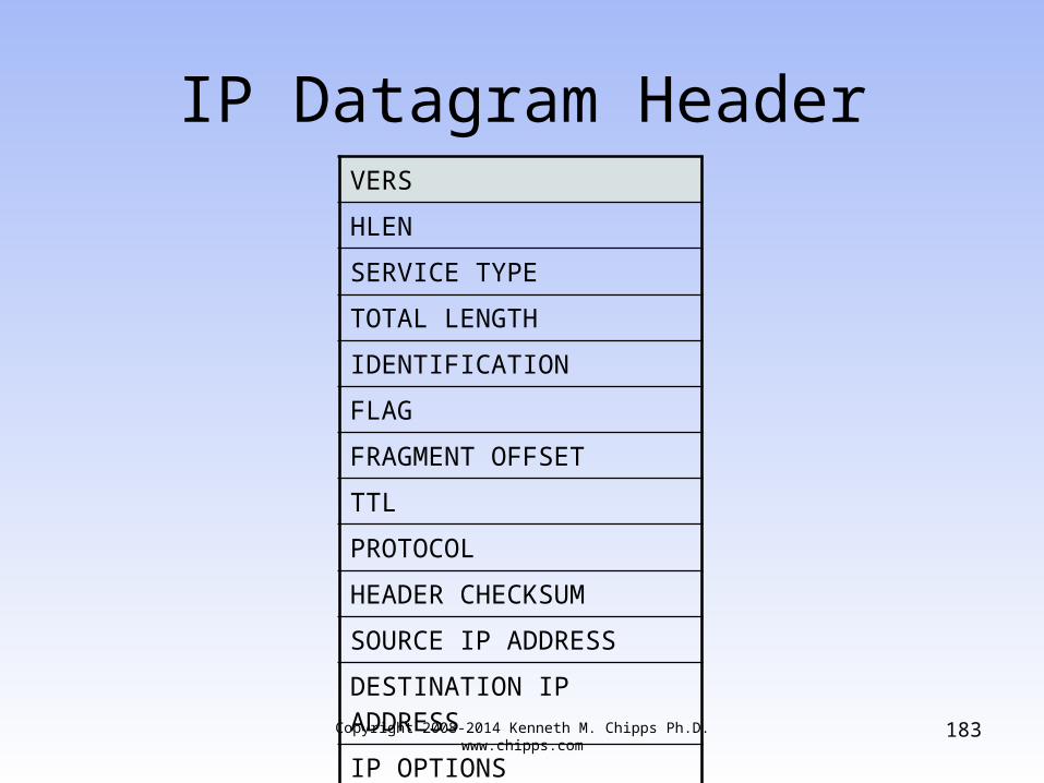
Copyright 2008-2014 Kenneth M. Chipps Ph.D. www.chipps.com
183
IP Datagram HeaderVERS
HLEN
SERVICE TYPE
TOTAL LENGTH
IDENTIFICATION
FLAG
FRAGMENT OFFSET
TTL
PROTOCOL
HEADER CHECKSUM
SOURCE IP ADDRESS
DESTINATION IP ADDRESS
IP OPTIONS

Copyright 2008-2014 Kenneth M. Chipps Ph.D. www.chipps.com
184
IP Datagram Header
• VERS or Version– 4 bits– The version of IP– Always 4 right now– Shows as binary 0100– To ensure everyone agrees on the format of
the datagram

Copyright 2008-2014 Kenneth M. Chipps Ph.D. www.chipps.com
185
IP Datagram HeaderVERS
HLEN
SERVICE TYPE
TOTAL LENGTH
IDENTIFICATION
FLAG
FRAGMENT OFFSET
TTL
PROTOCOL
HEADER CHECKSUM
SOURCE IP ADDRESS
DESTINATION IP ADDRESS
IP OPTIONS
Copyright 2008-2014 Kenneth M. Chipps Ph.D. www.chipps.com
186
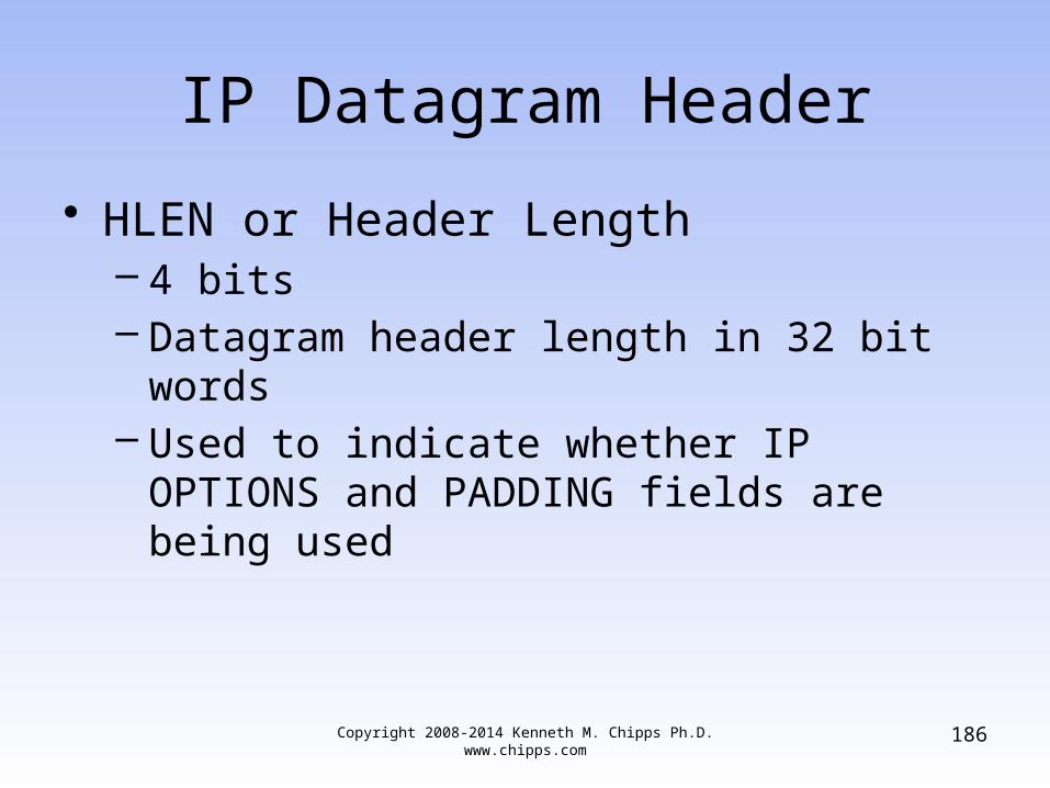
IP Datagram Header
• HLEN or Header Length– 4 bits– Datagram header length in 32 bit words– Used to indicate whether IP OPTIONS and
PADDING fields are being used

Copyright 2008-2014 Kenneth M. Chipps Ph.D. www.chipps.com
187
IP Datagram HeaderVERS
HLEN
SERVICE TYPE
TOTAL LENGTH
IDENTIFICATION
FLAG
FRAGMENT OFFSET
TTL
PROTOCOL
HEADER CHECKSUM
SOURCE IP ADDRESS
DESTINATION IP ADDRESS
IP OPTIONS

Copyright 2008-2014 Kenneth M. Chipps Ph.D. www.chipps.com
188
IP Datagram Header
• SERVICE TYPE– 8 bits– Specifies how the datagram should be
handled– QoS mechanism

Copyright 2008-2014 Kenneth M. Chipps Ph.D. www.chipps.com
189
IP Datagram HeaderVERS
HLEN
SERVICE TYPE
TOTAL LENGTH
IDENTIFICATION
FLAG
FRAGMENT OFFSET
TTL
PROTOCOL
HEADER CHECKSUM
SOURCE IP ADDRESS
DESTINATION IP ADDRESS
IP OPTIONS
Copyright 2008-2014 Kenneth M. Chipps Ph.D. www.chipps.com
190
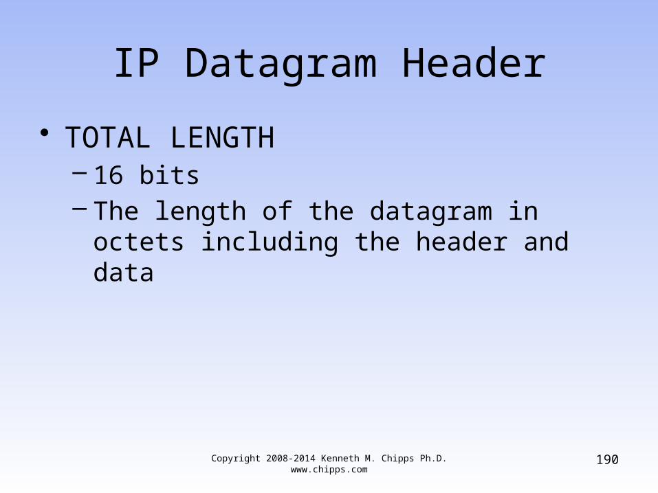
IP Datagram Header
• TOTAL LENGTH– 16 bits– The length of the datagram in octets including
the header and data

Copyright 2008-2014 Kenneth M. Chipps Ph.D. www.chipps.com
191
IP Datagram HeaderVERS
HLEN
SERVICE TYPE
TOTAL LENGTH
IDENTIFICATION
FLAG
FRAGMENT OFFSET
TTL
PROTOCOL
HEADER CHECKSUM
SOURCE IP ADDRESS
DESTINATION IP ADDRESS
IP OPTIONS

Copyright 2008-2014 Kenneth M. Chipps Ph.D. www.chipps.com
192
IP Datagram Header
• IDENTIFICATION or Fragment Identifier– 16 bits– Holds a unique integer that identifies which
datagram a fragment belongs to if the packet has been fragmented, which most are

Copyright 2008-2014 Kenneth M. Chipps Ph.D. www.chipps.com
193
IP Datagram Size
• Minimum datagram size is 576 bytes– With at least 552 bytes of data
• Maximum size for an IP datagram is 65,535 bytes– With at most 65,515 bytes of data
• But Ethernet only handles 1500 bytes of data• So how is a 65,535 byte datagram to go into a
1500 byte data area• By fragmentation
Copyright 2008-2014 Kenneth M. Chipps Ph.D. www.chipps.com
194
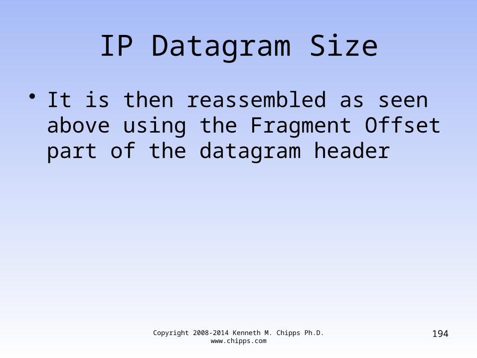
IP Datagram Size
• It is then reassembled as seen above using the Fragment Offset part of the datagram header

Copyright 2008-2014 Kenneth M. Chipps Ph.D. www.chipps.com
195
IP Datagram HeaderVERS
HLEN
SERVICE TYPE
TOTAL LENGTH
IDENTIFICATION
FLAG
FRAGMENT OFFSET
TTL
PROTOCOL
HEADER CHECKSUM
SOURCE IP ADDRESS
DESTINATION IP ADDRESS
IP OPTIONS

Copyright 2008-2014 Kenneth M. Chipps Ph.D. www.chipps.com
196
IP Datagram Header
• FLAG or Fragmentation Flag– 3 bits, but part of the FRAGMENT OFFSET
field– Indicating that the datagram has been
fragmented– Bit 1 is not currently used– Bit 2 is turned on to tell routers to not
fragment a packet• If the router must, but cannot, the packet is
dropped and a message is sent to the receiver

Copyright 2008-2014 Kenneth M. Chipps Ph.D. www.chipps.com
197
IP Datagram Header
– Bit 3 when on indicates more fragments are coming• When set to 0 it indicates this is the last fragment
– All of this information is used to reassemble everything

Copyright 2008-2014 Kenneth M. Chipps Ph.D. www.chipps.com
198
IP Datagram HeaderVERS
HLEN
SERVICE TYPE
TOTAL LENGTH
IDENTIFICATION
FLAG
FRAGMENT OFFSET
TTL
PROTOCOL
HEADER CHECKSUM
SOURCE IP ADDRESS
DESTINATION IP ADDRESS
IP OPTIONS

Copyright 2008-2014 Kenneth M. Chipps Ph.D. www.chipps.com
199
IP Datagram Header
• FRAGMENT OFFSET– 13 bits– This tells the receiver what piece of a
datagram this packet is of a datagram that has been cut up due to the MTU of the underlying method being used to carry the datagram from point-to-point

Copyright 2008-2014 Kenneth M. Chipps Ph.D. www.chipps.com
200
IP Datagram Header
– To distinguish fragments, each has its offset field set to the distance, measured in 8 byte units, between the beginning of the original datagram and the beginning of that particular fragment
– So the first fragment has an offset of 0, the second fragment has an offset value of the payload size of the first fragment, and so on

Copyright 2008-2014 Kenneth M. Chipps Ph.D. www.chipps.com
201
IP Datagram HeaderVERS
HLEN
SERVICE TYPE
TOTAL LENGTH
IDENTIFICATION
FLAG
FRAGMENT OFFSET
TTL
PROTOCOL
HEADER CHECKSUM
SOURCE IP ADDRESS
DESTINATION IP ADDRESS
IP OPTIONS
Copyright 2008-2014 Kenneth M. Chipps Ph.D. www.chipps.com
202
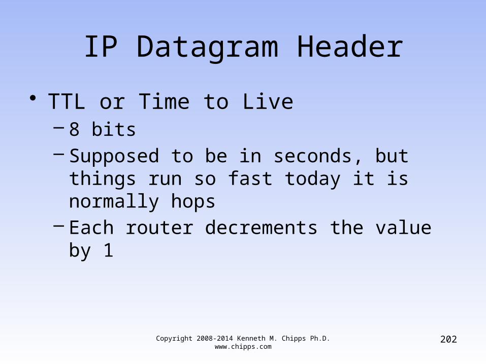
IP Datagram Header
• TTL or Time to Live– 8 bits– Supposed to be in seconds, but things run so
fast today it is normally hops– Each router decrements the value by 1
Copyright 2008-2014 Kenneth M. Chipps Ph.D. www.chipps.com
203
IP Datagram HeaderVERS
HLEN
SERVICE TYPE
TOTAL LENGTH
IDENTIFICATION
FLAG
FRAGMENT OFFSET
TTL
PROTOCOL
HEADER CHECKSUM
SOURCE IP ADDRESS
DESTINATION IP ADDRESS
IP OPTIONS
Copyright 2008-2014 Kenneth M. Chipps Ph.D. www.chipps.com
204
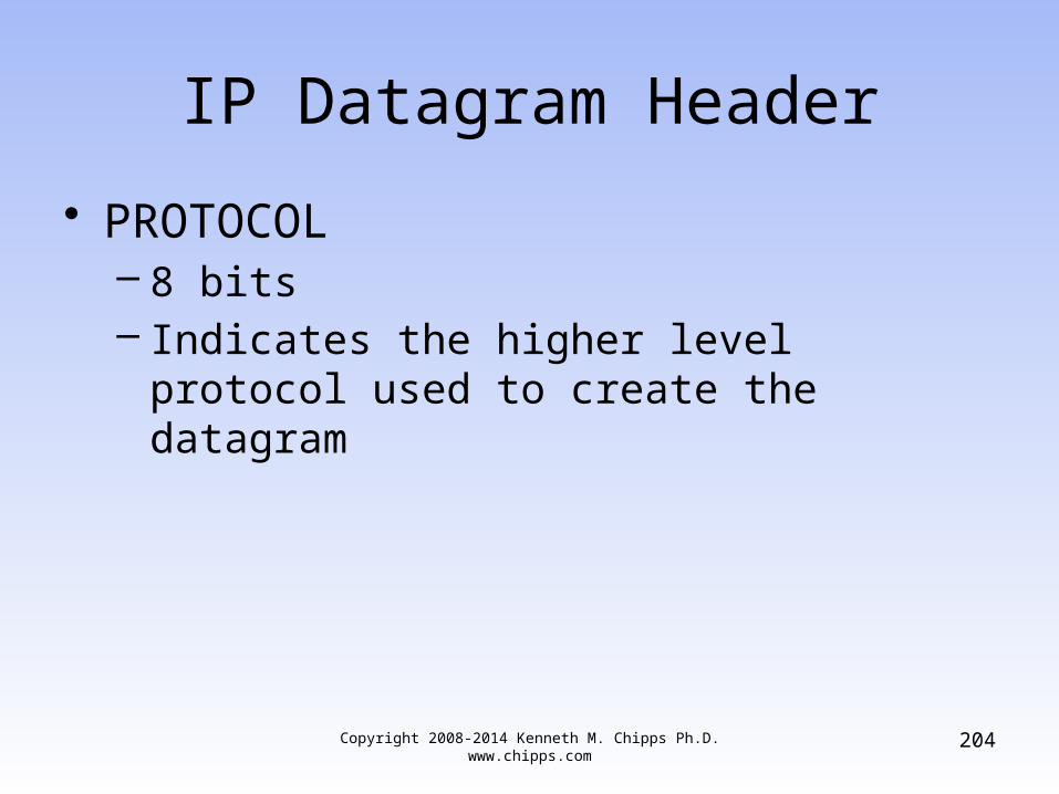
IP Datagram Header
• PROTOCOL– 8 bits– Indicates the higher level protocol used to
create the datagram

Copyright 2008-2014 Kenneth M. Chipps Ph.D. www.chipps.com
205
IP Datagram HeaderVERS
HLEN
SERVICE TYPE
TOTAL LENGTH
IDENTIFICATION
FLAG
FRAGMENT OFFSET
TTL
PROTOCOL
HEADER CHECKSUM
SOURCE IP ADDRESS
DESTINATION IP ADDRESS
IP OPTIONS

Copyright 2008-2014 Kenneth M. Chipps Ph.D. www.chipps.com
206
IP Datagram Header
• HEADER CHECKSUM– 16 bits– Checks the integrity of the header itself– Not the data, the header

Copyright 2008-2014 Kenneth M. Chipps Ph.D. www.chipps.com
207
IP Datagram HeaderVERS
HLEN
SERVICE TYPE
TOTAL LENGTH
IDENTIFICATION
FLAG
FRAGMENT OFFSET
TTL
PROTOCOL
HEADER CHECKSUM
SOURCE IP ADDRESS
DESTINATION IP ADDRESS
IP OPTIONS

Copyright 2008-2014 Kenneth M. Chipps Ph.D. www.chipps.com
208
IP Datagram Header
• SOURCE IP ADDRESS– 32 bits– Where it came from

Copyright 2008-2014 Kenneth M. Chipps Ph.D. www.chipps.com
209
IP Datagram HeaderVERS
HLEN
SERVICE TYPE
TOTAL LENGTH
IDENTIFICATION
FLAG
FRAGMENT OFFSET
TTL
PROTOCOL
HEADER CHECKSUM
SOURCE IP ADDRESS
DESTINATION IP ADDRESS
IP OPTIONS
Copyright 2008-2014 Kenneth M. Chipps Ph.D. www.chipps.com
210
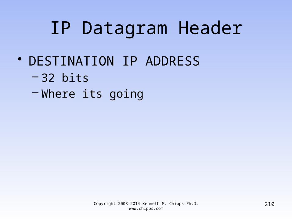
IP Datagram Header
• DESTINATION IP ADDRESS– 32 bits– Where its going

Copyright 2008-2014 Kenneth M. Chipps Ph.D. www.chipps.com
211
IP Datagram HeaderVERS
HLEN
SERVICE TYPE
TOTAL LENGTH
IDENTIFICATION
FLAG
FRAGMENT OFFSET
TTL
PROTOCOL
HEADER CHECKSUM
SOURCE IP ADDRESS
DESTINATION IP ADDRESS
IP OPTIONS

Copyright 2008-2014 Kenneth M. Chipps Ph.D. www.chipps.com
212
IP Datagram Header
• IP OPTIONS– 24 bits– Not used except in testing

Copyright 2008-2014 Kenneth M. Chipps Ph.D. www.chipps.com
213
IP Datagram Header
• PADDING– 8 bits– To bring the datagram up to a minimum size

Copyright 2008-2014 Kenneth M. Chipps Ph.D. www.chipps.com
214
IP Datagram Header
• DATA– Size varies– The important stuff

Copyright 2008-2014 Kenneth M. Chipps Ph.D. www.chipps.com
215
Ethernet II Frame Format
Field Bytes
Preamble 8
Destination Address 6
Source Address 6
Type 2
Data 46-1500
Frame Check Sequence 4
Copyright 2008-2014 Kenneth M. Chipps Ph.D. www.chipps.com
216
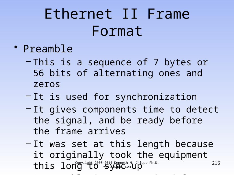
Ethernet II Frame Format
• Preamble– This is a sequence of 7 bytes or 56 bits of
alternating ones and zeros– It is used for synchronization– It gives components time to detect the signal,
and be ready before the frame arrives– It was set at this length because it originally
took the equipment this long to sync up– A preamble is not required for speeds above
10 Mbps
Copyright 2008-2014 Kenneth M. Chipps Ph.D. www.chipps.com
217
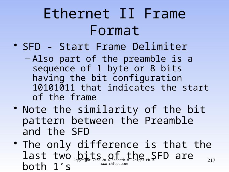
Ethernet II Frame Format
• SFD - Start Frame Delimiter– Also part of the preamble is a sequence of 1
byte or 8 bits having the bit configuration 10101011 that indicates the start of the frame
• Note the similarity of the bit pattern between the Preamble and the SFD
• The only difference is that the last two bits of the SFD are both 1’s
• Many people do not separate the Preamble and Start Frame Delimiter

Copyright 2008-2014 Kenneth M. Chipps Ph.D. www.chipps.com
218
Ethernet II Frame Format
• They consider it to all be the preamble• Because it takes a station an unknowable
amount of time to lock on, it does not know how many bits of the Preamble have gone by
• For this reason, it is said that the Preamble is lost in the synching up process
Copyright 2008-2014 Kenneth M. Chipps Ph.D. www.chipps.com
219
Ethernet II Frame Format
• As such no part of the Preamble ever enters the NIC’s buffer
• This is why the size of the Preamble/SFD is excluded when the minimum and maximum Ethernet frame sizes are discussed

Copyright 2008-2014 Kenneth M. Chipps Ph.D. www.chipps.com
220
Ethernet II Frame Format
• Destination Address– This is the MAC address of the station the
message is for– This address may specify either an individual
address destined for a single station, a multicast address destined for a group of stations, or an address of all 1s bits that refers to all stations on the LAN and is called a broadcast address

Copyright 2008-2014 Kenneth M. Chipps Ph.D. www.chipps.com
221
Ethernet II Frame Format
• Source Address– This is the MAC address of the sending
station• Type
– Type indicates the protocol type that the frame is for at the network layer, such as• 0800 for TCP/IP• 8137 for IPX
– These are hexadecimal numbers

Copyright 2008-2014 Kenneth M. Chipps Ph.D. www.chipps.com
222
Ethernet II Frame Format
• Data– This is the important stuff and has a maximum
size of 1500 bytes– If the size is less than 46 bytes, then bytes
are placed in the Pad field to bring the frame length up to at least 64 bytes
– What goes into this data area is the original message and the headers placed in front of that message at each of those layers
Copyright 2008-2014 Kenneth M. Chipps Ph.D. www.chipps.com
223
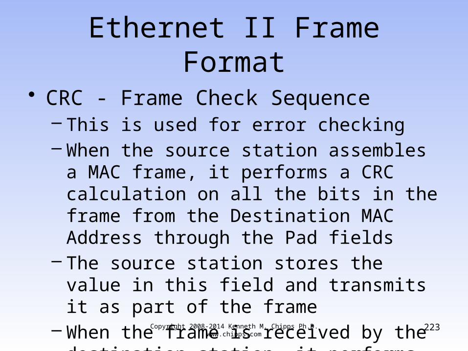
Ethernet II Frame Format
• CRC - Frame Check Sequence– This is used for error checking– When the source station assembles a MAC
frame, it performs a CRC calculation on all the bits in the frame from the Destination MAC Address through the Pad fields
– The source station stores the value in this field and transmits it as part of the frame
– When the frame is received by the destination station, it performs an identical check

Copyright 2008-2014 Kenneth M. Chipps Ph.D. www.chipps.com
224
Ethernet II Frame Format
– If the calculated value does not match the value in this field, the destination station assumes an error has occurred during transmission and discards the frame

Lab
• Start Wireshark• Capture a few frames• Examine the IP header• Examine the Ethernet header
Copyright 2008-2014 Kenneth M. Chipps Ph.D. www.chipps.com
225