controller editor manual english - samash music · pdf filecontroller editor - manual - 10. 1...
TRANSCRIPT

Manual
The information in this document is subject to change without notice and does not represent acommitment on the part of Native Instruments GmbH. The software described by this docu-ment is subject to a License Agreement and may not be copied to other media. No part of thispublication may be copied, reproduced or otherwise transmitted or recorded, for any purpose,without prior written permission by Native Instruments GmbH, hereinafter referred to as NativeInstruments.
“Native Instruments”, “NI” and associated logos are (registered) trademarks of Native Instru-ments GmbH.
Mac, Mac OS, GarageBand, Logic, iTunes and iPod are registered trademarks of Apple Inc.,registered in the U.S. and other countries.Windows, Windows Vista and DirectSound are registered trademarks of Microsoft Corporationin the United States and/or other countries.All other trade marks are the property of their respective owners and use of them does not im-ply any affiliation with or endorsement by them.
Document authored by: Native Instruments GmbH
Software version: 1.5.1 (09/2012)
Special thanks to the Beta Test Team, who were invaluable not just in tracking down bugs, butin making this a better product.
Disclaimer

Germany
Native Instruments GmbHSchlesische Str. 29-30D-10997 BerlinGermanywww.native-instruments.de
USA
Native Instruments North America, Inc.6725 Sunset Boulevard5th FloorLos Angeles, CA 90028USAwww.native-instruments.com
© Native Instruments GmbH, 2012. All rights reserved.
Contact

Table of Contents1 Welcome to the Controller Editor! ...............................................................................11
1.1 About This Manual ...................................................................................................................... 11
1.2 Document Conventions ............................................................................................................... 12
2 Installation ...............................................................................................................14
2.1 Controller Editor as Part of a NI Product Installation .................................................................. 14
2.2 Downloading the Controller Editor from the Native Instruments Website .................................... 15
3 Quick Start ................................................................................................................16
3.1 Switching your NI Controller to MIDI Mode .................................................................................. 17
3.2 Loading MIDI Assignments ......................................................................................................... 19
3.2.1 Select the NI Controller .............................................................................................. 19
3.2.2 Select a Template ...................................................................................................... 21
3.2.3 Select a Knob Page .................................................................................................... 22
3.2.4 Select a Pad Page (MASCHINE Controller Family Only) .............................................. 24
3.2.5 Ready to Go? .............................................................................................................. 26
3.3 Modifying an Assignment ........................................................................................................... 26
3.4 Organizing Your Assignments ..................................................................................................... 28
3.4.1 Displaying the Lists of Templates and Pages ............................................................ 28
3.4.2 Renaming Templates and Pages ............................................................................... 28
3.4.3 Re-ordering Templates and Pages ............................................................................. 29
3.5 Saving and Loading Templates .................................................................................................. 30
4 Basic Concepts .........................................................................................................32
4.1 How the Controller Editor Works .................................................................................................. 32
4.2 Overview of the User Interface .................................................................................................... 32
4.2.1 Application Menu Bar ................................................................................................ 34
4.2.2 Application Control Bar ............................................................................................. 34
4.2.3 Hardware Area ........................................................................................................... 35
Table of Contents
Controller Editor - Manual - 4
4.2.4 Inspector ................................................................................................................... 36
4.3 The Mapping System .................................................................................................................. 42
4.3.1 Assignments .............................................................................................................. 42
4.3.2 Knob Pages ................................................................................................................ 42
4.3.3 Pad Pages (MASCHINE Controller Family Only) .......................................................... 43
4.3.4 Templates .................................................................................................................. 43
4.3.5 Configuration ............................................................................................................ 45
4.4 To sum up… .............................................................................................................................. 45
5 Using Your MASCHINE Controller ...............................................................................46
5.1 Basic Controls ............................................................................................................................ 46
5.2 Assignable Control Elements ...................................................................................................... 48
5.3 Visual Feedback on your Controller ............................................................................................. 51
5.3.1 Buttons ...................................................................................................................... 51
5.3.2 Pads .......................................................................................................................... 52
5.3.3 Knobs ........................................................................................................................ 53
5.4 The Displays ............................................................................................................................... 53
5.4.1 Switching Between Display Modes ............................................................................. 53
5.4.2 Knobs Display Mode ................................................................................................... 54
5.4.3 Pad Pages Display Mode ............................................................................................ 55
5.4.4 Knob Pages Display Mode .......................................................................................... 56
5.4.5 Template Display Mode .............................................................................................. 57
5.4.6 Monitor Display Mode ................................................................................................ 57
5.4.7 Settings Display Mode ............................................................................................... 58
6 Using Your MASCHINE MK2 Controller .......................................................................59
6.1 Basic Controls ............................................................................................................................ 59
6.2 Assignable Control Elements ...................................................................................................... 61
6.3 Visual Feedback on your Controller ............................................................................................. 64
6.3.1 Buttons ...................................................................................................................... 65
Table of Contents
Controller Editor - Manual - 5

6.3.2 Multicolor Pads .......................................................................................................... 66
6.3.3 Knobs ........................................................................................................................ 67
6.3.4 Control Encoder ......................................................................................................... 67
6.4 The Displays ............................................................................................................................... 67
6.4.1 Switching Between Display Modes ............................................................................. 67
6.4.2 Knobs Display Mode ................................................................................................... 68
6.4.3 Pad Pages Display Mode ............................................................................................ 69
6.4.4 Knob Pages Display Mode .......................................................................................... 70
6.4.5 Template Display Mode .............................................................................................. 71
6.4.6 Monitor Display Mode ................................................................................................ 72
6.4.7 Settings Display Mode ............................................................................................... 72
7 Using Your MASCHINE MIKRO Controller ....................................................................74
7.1 Basic Controls ............................................................................................................................ 74
7.2 Assignable Control Elements ...................................................................................................... 76
7.3 Visual Feedback on your Controller ............................................................................................. 78
7.3.1 Buttons ...................................................................................................................... 79
7.3.2 Pads .......................................................................................................................... 79
7.3.3 Control Encoder ......................................................................................................... 80
7.4 The Display ................................................................................................................................. 80
7.4.1 Switching Between Display Modes ............................................................................. 80
7.4.2 Control Display Mode ................................................................................................. 81
7.4.3 Template Display Mode .............................................................................................. 82
7.4.4 Setup Display Mode ................................................................................................... 83
8 Using Your MASCHINE MIKRO MK2 Controller .............................................................84
8.1 Basic Controls ............................................................................................................................ 84
8.2 Assignable Control Elements ...................................................................................................... 86
8.3 Visual Feedback on your Controller ............................................................................................. 88
8.3.1 Buttons ...................................................................................................................... 88
Table of Contents
Controller Editor - Manual - 6

8.3.2 Multicolor Pads .......................................................................................................... 90
8.3.3 Control Encoder ......................................................................................................... 91
8.4 The Display ................................................................................................................................. 91
8.4.1 Switching Between Display Modes ............................................................................. 91
8.4.2 Control Display Mode ................................................................................................. 92
8.4.3 Template Display Mode .............................................................................................. 92
8.4.4 Setup Display Mode ................................................................................................... 93
9 Using Your KORE Controller .......................................................................................95
9.1 Basic Controls ............................................................................................................................ 95
9.2 Assignable Control Elements ...................................................................................................... 98
9.2.1 KORE 2 Controller ...................................................................................................... 98
9.2.2 KORE 1 Controller ...................................................................................................... 100
9.3 Visual Feedback on your Controller ............................................................................................. 100
9.3.1 Buttons ...................................................................................................................... 100
9.3.2 Controller Knobs ........................................................................................................ 101
9.3.3 Scrollwheel ................................................................................................................ 102
9.3.4 Pedal Inputs and Footswitch Ports ............................................................................ 102
9.4 The Display ................................................................................................................................. 102
9.4.1 Switching between Display Modes ............................................................................. 102
9.4.2 Control Display Mode ................................................................................................. 104
9.4.3 Knob Pages Display Mode .......................................................................................... 106
9.4.4 Setup Display Mode ................................................................................................... 107
9.4.5 Options Display Mode ................................................................................................ 107
9.4.6 Templates Display Mode ............................................................................................ 108
10 Using Your TRAKTOR KONTROL X1 ..............................................................................110
10.1 Basic Controls ............................................................................................................................ 110
10.2 Assignable Control Elements ...................................................................................................... 111
10.3 Visual Feedback on your Controller ............................................................................................. 113
Table of Contents
Controller Editor - Manual - 7

10.4 Using Two or More TRAKTOR KONTROL X1 Units ......................................................................... 114
11 Using Your TRAKTOR KONTROL F1 ..............................................................................115
11.1 Basic Controls ............................................................................................................................ 115
11.2 Assignable Control Elements ...................................................................................................... 116
11.3 Visual Feedback on Your Controller ............................................................................................ 118
11.3.1 Buttons and Pads ...................................................................................................... 119
11.3.2 7-segment Display .................................................................................................... 120
11.4 Using Two or More TRAKTOR KONTROL F1 Units .......................................................................... 121
12 Using Your TRAKTOR KONTROL S4 ..............................................................................122
12.1 Basic Controls ............................................................................................................................ 122
12.2 Assignable Control Elements ...................................................................................................... 125
12.2.1 Control Elements on the Left Deck ............................................................................. 125
12.2.2 Control Elements on the Right Deck .......................................................................... 127
12.2.3 Control Elements on the Mixer ................................................................................... 127
12.2.4 Assignment Parameters ............................................................................................ 129
12.3 Visual Feedback on your Controller ............................................................................................. 129
12.3.1 Buttons ...................................................................................................................... 130
12.3.2 LED Chains ................................................................................................................ 131
13 Using Your TRAKTOR KONTROL S2 ..............................................................................132
13.1 Basic Controls ............................................................................................................................ 132
13.2 Assignable Control Elements ...................................................................................................... 133
13.3 Visual Feedback on your Controller ............................................................................................. 134
13.3.1 Buttons ...................................................................................................................... 134
13.3.2 LED Chains ................................................................................................................ 135
14 Using Your RIG KONTROL 3 ........................................................................................136
14.1 Basic Controls ............................................................................................................................ 136
14.2 Assignable Control Elements ...................................................................................................... 137
14.3 Visual Feedback on your Controller ............................................................................................. 138
Table of Contents
Controller Editor - Manual - 8

14.3.1 Footswitches .............................................................................................................. 139
14.3.2 Expression Pedal ....................................................................................................... 139
14.3.3 Pedal Inputs .............................................................................................................. 140
14.4 The Display ................................................................................................................................. 140
15 Using Your AUDIO KONTROL 1 ....................................................................................141
15.1 Basic Controls ............................................................................................................................ 141
15.2 Assignable Control Elements ...................................................................................................... 142
15.3 Visual Feedback on your Controller ............................................................................................. 143
15.3.1 Left Button ................................................................................................................ 143
15.3.2 Controller Knob .......................................................................................................... 143
15.3.3 Middle and Right Buttons .......................................................................................... 144
16 Using Two or More Units of the Same Type .................................................................145
16.1 Renaming the Units .................................................................................................................... 145
16.2 Accessing Templates and Knob Pages of a Particular Unit ......................................................... 147
16.3 Resolving Device Conflicts ......................................................................................................... 148
17 Reference .................................................................................................................150
17.1 The Application Menu Bar ........................................................................................................... 150
17.1.1 File Menu ................................................................................................................... 150
17.1.2 View Menu ................................................................................................................. 151
17.1.3 Help Menu ................................................................................................................. 152
17.2 The Preferences Window ............................................................................................................. 152
17.2.1 General Page ............................................................................................................. 153
17.2.2 Controller Page .......................................................................................................... 154
17.3 The Application Control Bar ........................................................................................................ 160
17.3.1 Device Menu .............................................................................................................. 161
17.3.2 Connect Button .......................................................................................................... 162
17.3.3 Template Select Menu ............................................................................................... 163
17.3.4 Minimize/Expand View Button ................................................................................... 163
Table of Contents
Controller Editor - Manual - 9
17.3.5 MIDI Activity Indicator ............................................................................................... 166
17.3.6 NI Logo ...................................................................................................................... 166
17.4 The Hardware Area ..................................................................................................................... 167
17.4.1 Label Fields ............................................................................................................... 167
17.4.2 Selection Frame ......................................................................................................... 168
17.4.3 Knob Page Area and Knob Page Menu ....................................................................... 168
17.4.4 Page Buttons (MASCHINE Controllers Only) and Left/Right Arrow Buttons (MA-
SCHINE MIKRO Controllers Only) ................................................................................ 170
17.4.5 Pad Page Area and Pad Page Menu (MASCHINE and MASCHINE MIKRO Controllers
Only) .......................................................................................................................... 171
17.5 The Inspector .............................................................................................................................. 173
17.5.1 Templates Page ......................................................................................................... 174
17.5.2 Pages Page ................................................................................................................ 180
17.5.3 Assign Page ............................................................................................................... 187
17.6 MIDI Message Parameters .......................................................................................................... 190
17.6.1 MIDI Message Types – Type Menu .............................................................................. 191
17.6.2 Assignments for Buttons and the Like ....................................................................... 194
17.6.3 Assignments for the Pads – Hit Action ...................................................................... 199
17.6.4 Assignments for Knobs and the Like .......................................................................... 199
17.6.5 Assignments for the Pads – Press Action .................................................................. 200
17.6.6 Assignments for Digital Encoders and the Like ......................................................... 201
17.6.7 Assignments for Analog Encoders and the Like ......................................................... 203
17.6.8 Assignments for the LED Chains and 7-segment Displays ........................................ 205
Table of Contents
Controller Editor - Manual - 10

1 Welcome to the Controller Editor!
This powerful tool turns your Native Instruments hardware controller device into a versatile andefficient MIDI remote control for your studio and/or live setup.
With the Controller Editor, you can precisely define which MIDI message has to be sent uponany action you do on your NI controller. This way, you can put your whole music setup right atyour fingertips and remote control every MIDI-capable software or hardware from your NI con-troller. After having prepared your MIDI assignments with the Controller Editor, you can focuson what it’s all about: making music!
Yours sincerely,
The team at Native Instruments
1.1 About This Manual
This manual is divided into four parts:
▪ The first part introduces you to the Controller Editor: after a short description of the in-stallation procedure (chapter ↑2, Installation), we will start with a brief tutorial (chapter↑3, Quick Start).
▪ The second part illustrates the software’s user interface, the Controller Editor’s mappingscheme and the various ways to interact with the software (chapter ↑4, Basic Concepts).This will familiarize you with Controller Editor’s workflow.
▪ The third part shows you how to use your particular NI controller(s):
◦ chapter ↑5, Using Your MASCHINE Controller,
◦ chapter ↑6, Using Your MASCHINE MK2 Controller,
◦ chapter ↑7, Using Your MASCHINE MIKRO Controller,
◦ chapter ↑8, Using Your MASCHINE MIKRO MK2 Controller,
◦ chapter ↑9, Using Your KORE Controller,
◦ chapter ↑10, Using Your TRAKTOR KONTROL X1,
Welcome to the Controller Editor!
About This Manual
Controller Editor - Manual - 11
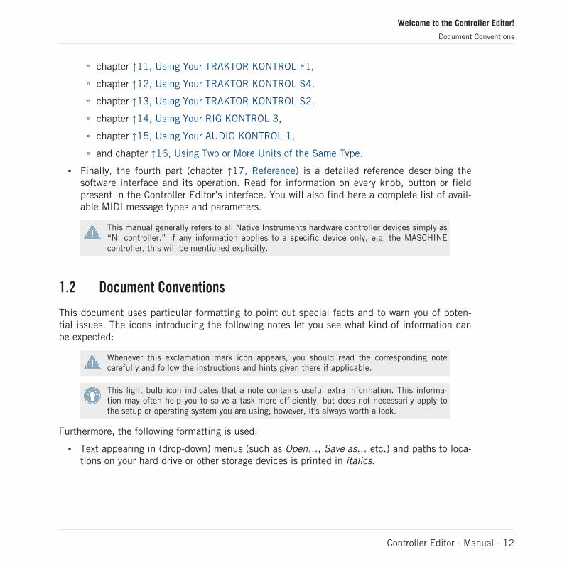
◦ chapter ↑11, Using Your TRAKTOR KONTROL F1,
◦ chapter ↑12, Using Your TRAKTOR KONTROL S4,
◦ chapter ↑13, Using Your TRAKTOR KONTROL S2,
◦ chapter ↑14, Using Your RIG KONTROL 3,
◦ chapter ↑15, Using Your AUDIO KONTROL 1,
◦ and chapter ↑16, Using Two or More Units of the Same Type.
▪ Finally, the fourth part (chapter ↑17, Reference) is a detailed reference describing thesoftware interface and its operation. Read for information on every knob, button or fieldpresent in the Controller Editor’s interface. You will also find here a complete list of avail-able MIDI message types and parameters.
This manual generally refers to all Native Instruments hardware controller devices simply as“NI controller.” If any information applies to a specific device only, e.g. the MASCHINEcontroller, this will be mentioned explicitly.
1.2 Document Conventions
This document uses particular formatting to point out special facts and to warn you of poten-tial issues. The icons introducing the following notes let you see what kind of information canbe expected:
Whenever this exclamation mark icon appears, you should read the corresponding notecarefully and follow the instructions and hints given there if applicable.
This light bulb icon indicates that a note contains useful extra information. This informa-tion may often help you to solve a task more efficiently, but does not necessarily apply tothe setup or operating system you are using; however, it's always worth a look.
Furthermore, the following formatting is used:
▪ Text appearing in (drop-down) menus (such as Open…, Save as… etc.) and paths to loca-tions on your hard drive or other storage devices is printed in italics.
Welcome to the Controller Editor!
Document Conventions
Controller Editor - Manual - 12

▪ Text appearing elsewhere on the screen (labels of buttons, controls, text next to checkbox-es etc.) is printed in light blue. Whenever you see this formatting applied, you will findthe same text appearing on the screen.
▪ Important names and concepts are printed in bold.
▪ References to keys on your computer’s keyboard you’ll find put in square brackets (e.g.,“Press [Shift] + [Return]”).
1. Sequences of ordered instructions are introduced by numbers.
► Single instructions are introduced by this play button type arrow.
→ Results of actions are introduced by this smaller arrow.
Welcome to the Controller Editor!
Document Conventions
Controller Editor - Manual - 13
2 Installation
This chapter describes how to install the Controller Editor in various situations.
2.1 Controller Editor as Part of a NI Product Installation
Whether you own a NI product consisting of a hardware controller and its dedicated software(e.g. MASCHINE, TRAKTOR KONTROL S4, GUITAR RIG KONTROL, KORE 2) or a NI control-ler sold as hardware-only product (e.g. RIG KONTROL 3, or AUDIO KONTROL 1), the Control-ler Editor is included in the product software package and was automatically installed duringthe installation procedure for your NI product. Therefore, normally it does not need any specif-ic installation.
We assume here that your NI product (hardware-software system or hardware-only) is al-ready installed on your computer. For a detailed description of this installation procedure,please refer to the Setup Guide provided with your NI product.
You should find the Controller Editor at the following locations:
▪ Mac OS X: Applications/Native Instruments/Controller Editor
▪ Windows: Program Files\Native Instruments\Controller Editor
If for any reason the Controller Editor is not installed on your computer, please check that yourNI product is up to date. You can do this easily via the Service Center or via the Native Instru-ments website. If updates are available for your product, download and install them.
You can also download a stand-alone installer for the Controller Editor from the Native Instru-ments website — see next section for more info.
Installation
Controller Editor as Part of a NI Product Installation
Controller Editor - Manual - 14

2.2 Downloading the Controller Editor from the Native InstrumentsWebsite
Apart from being included in the software package of supported NI products, the ControllerEditor is also available for download, both as part of the hardware driver installer and as stand-alone installer.
It is strongly recommended to download and install the hardware driver installer rather thanthe Controller Editor stand-alone installer — besides installing the Controller Editor, thisensures that the drivers for your NI controller are both correctly installed and up-to-date.
If your NI controller is already installed on your computer, use the Service Center to downloadthe last driver updates. The driver packages include the Controller Editor.
If your NI controller is not installed on your computer yet, you can manually download thehardware drivers for your NI controller along with the Controller Editor. To do this:
1. Open your favorite internet browser and go to the following URL:http://www.native-instruments.com/updates
2. On this page, follow the link to the unprotected updates, drivers and the Service Center.3. In the list of available downloads, follow the link to your specific NI controller.4. Download the installer file for your operating system (Windows or Mac OS X) and save it to
your hard disk.5. Navigate to the directory where you saved the installer file and double-click it.
This launches the installer.6. The installation process is straightforward: follow the instructions on the screen and
you’re done.
Installation
Downloading the Controller Editor from the Native Instruments Website
Controller Editor - Manual - 15
3 Quick Start
This chapter provides a hands-on introduction to the Controller Editor.
We assume here that the Controller Editor is already installed on your computer. See chap-ter ↑2, Installation for more info.
The use of the Controller Editor is straightforward. Most actions can be done either from yourNI controller or via the Controller Editor interface, and this in various ways — you can choosethe one that best fits your needs.
In this chapter, we will successively show you how to:
1. Switch your NI controller to MIDI mode.2. Load MIDI assignments for a specific task: Select a whole set of assignments (known as a
Template) for your controller; Select a particular subset of assignments (known as a KnobPage) for specific control elements on your controller; MASCHINE (MIKRO) controller on-ly: Select an additional subset of assignments (known as a Pad Page) for the pads.
3. Modify assignments to make them perfectly fit your own needs.4. Organize your customized assignments.5. Save and recall the whole set of assignments as a Template.
In this chapter, we will often focus on the Controller Editor interface. But the actions pre-sented here can also be done from most NI controllers — and for a few of them, even invarious ways. Notably, this is very handy in live situations. For each task, we provide here alittle summary table with the corresponding shortcuts on the different NI controllers. Formore info on all you can do from your controller, please refer to the respective controller-specific chapters, later in this manual.
For details about each and every element in the Controller Editor user interface, please re-fer to chapter ↑17, Reference.
For details about each and every element in the Controller Editor user interface, please re-fer to chapter ↑17, Reference.
Preparations
At this point, we assume that:
Quick Start
Controller Editor - Manual - 16

▪ Your computer is up and running.
▪ You have already installed your NI controller and the Controller Editor (see chapter ↑2, In-stallation).
▪ Your NI controller is physically connected to your computer via the USB 2.0 cable.
3.1 Switching your NI Controller to MIDI Mode
First of all, let’s switch your NI controller to MIDI mode.
Indeed, your NI controller can run in two different and mutually exclusive modes:
▪ In Application mode, it controls its dedicated software (e.g. MASCHINE software) via theNative Instruments’ ultra fast high-resolution proprietary NHL protocol. Depending on therespective software, this mode will be called MASCHINE mode, TRAKTOR mode, or KOREmode.
▪ In MIDI mode, it can control any MIDI target(s) available (software or hardware) via theMIDI protocol.
Switch to MIDI Mode Directly from your NI Controller
It is not necessary to start the Controller Editor software in order to switch your NI controller toMIDI mode: you can do it directly from your controller (except for the RIG KONTROL 3).
For each NI controller, the following table shows you how to switch to/from MIDI mode andhow to quickly see whether your controller currently is in MIDI mode or not:
NI Controller Switching to/from MIDI mode Checking that MIDI mode is on
AUDIO KONTROL 1 n/a (always in MIDI mode)
KORE 1 Controller VIEW, then CONTROL Pressing VIEW displays the list of MIDITemplates
KORE 2 Controller F1, then CONTROL Pressing F1 displays the list of MIDI Tem-plates
MASCHINE MK2 SHIFT + CONTROL SHIFT button dimly lit
MASCHINE SHIFT + CONTROL SHIFT button dimly lit
Quick Start
Switching your NI Controller to MIDI Mode
Controller Editor - Manual - 17

NI Controller Switching to/from MIDI mode Checking that MIDI mode is on
MASCHINE MIKRO MK2 SHIFT + F1 SHIFT button dimly lit
MASCHINE MIKRO SHIFT + F1 SHIFT button dimly lit
RIG KONTROL 3 n/a (via the Controller Editor only) LED Display reading “con”
TRAKTOR KONTROL S2 SHIFT + SHIFT (on both Decks) Both SHIFT buttons dimly lit
TRAKTOR KONTROL S4 SHIFT + BROWSE button Loop Size Displays reading “ON”
TRAKTOR KONTROL X1 SHIFT + HOTCUE HOTCUE button lit in green
TRAKTOR KONTROL F1 SHIFT + BROWSE SHIFT button lit
AUDIO KONTROL 1: The MIDI mode is the only available mode and it is always active.Hence, there is no need for any kind of mode switching.
RIG KONTROL 3: There is no way for switching to MIDI mode from your RIG KONTROL 3.To switch your controller to MIDI mode, use the Controller Editor as described in the nextsection.
More info on this in the respective controller-specific chapters, later in this manual.
Switch to MIDI Mode by Starting the Controller Editor
You can also switch all your connected NI controllers to MIDI mode by starting the ControllerEditor:
► Start the Controller Editor by selecting Start > All Programs > Native Instruments > Con-troller Editor > Controller Editor (Windows) or Applications > Native Instruments > Con-troller Editor (Mac OS X).
→ This not only opens the Controller Editor, but also automatically switches any connectedcontroller(s) to MIDI mode.
If the Controller Editor is already open, you can check at any time whether your NI control-ler is in MIDI mode or not, and if not, switch it back to MIDI mode via the Device menuand the Connect button nearby — see ↑3.2.1, Select the NI Controller below.
Quick Start
Switching your NI Controller to MIDI Mode
Controller Editor - Manual - 18

Whichever method you have used, when switching your controller(s) to MIDI mode, the lastused MIDI assignments are automatically loaded along with their last state of use. If you arestarting the Controller Editor for the first time, the default MIDI assignments for your control-ler(s) are loaded instead.
You can start right away using your NI controller as a MIDI remote control!
3.2 Loading MIDI Assignments
In order to load other MIDI assignments for your NI controller, we will use the Controller Edi-tor.
As already mentioned, this can also be done from most NI controllers — see the controller-specific chapters, later in this manual.
At the top of the Controller Editor window, you see a horizontal bar with a series of controlsending in the NI logo at the far right. We call this bar the Application Control Bar:
The Application Control Bar, at the top of the Controller Editor window.
We will use the Application Control Bar to start loading new MIDI assignments.
3.2.1 Select the NI Controller
We first have to select the NI controller for which we want to load the MIDI assignments.
To select a controller:
► Click the Device menu (the first control from the left in the Application Control Bar), andselect the desired controller in the menu.
Quick Start
Loading MIDI Assignments
Controller Editor - Manual - 19
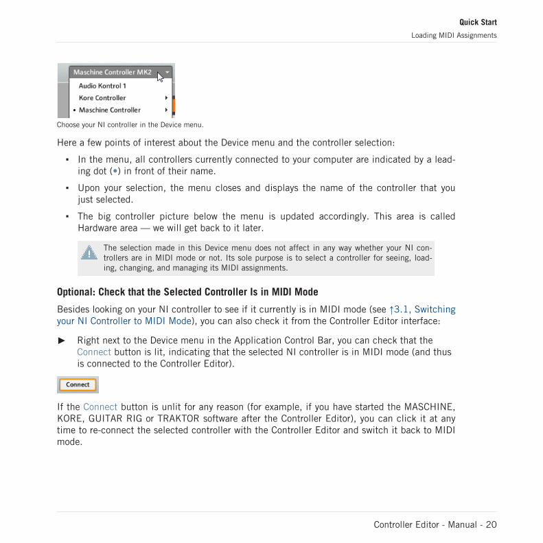
Choose your NI controller in the Device menu.
Here a few points of interest about the Device menu and the controller selection:
▪ In the menu, all controllers currently connected to your computer are indicated by a lead-ing dot (•) in front of their name.
▪ Upon your selection, the menu closes and displays the name of the controller that youjust selected.
▪ The big controller picture below the menu is updated accordingly. This area is calledHardware area — we will get back to it later.
The selection made in this Device menu does not affect in any way whether your NI con-trollers are in MIDI mode or not. Its sole purpose is to select a controller for seeing, load-ing, changing, and managing its MIDI assignments.
Optional: Check that the Selected Controller Is in MIDI Mode
Besides looking on your NI controller to see if it currently is in MIDI mode (see ↑3.1, Switchingyour NI Controller to MIDI Mode), you can also check it from the Controller Editor interface:
► Right next to the Device menu in the Application Control Bar, you can check that theConnect button is lit, indicating that the selected NI controller is in MIDI mode (and thusis connected to the Controller Editor).
If the Connect button is unlit for any reason (for example, if you have started the MASCHINE,KORE, GUITAR RIG or TRAKTOR software after the Controller Editor), you can click it at anytime to re-connect the selected controller with the Controller Editor and switch it back to MIDImode.
Quick Start
Loading MIDI Assignments
Controller Editor - Manual - 20
If the Connect button is grayed out and inactive, your NI controller might be disconnectedfrom your computer. Check the USB connection — if your controller is connected, ensurethat its drivers are properly installed (for more info, see chapter ↑2, Installation).
Your NI controller does not have necessarily to be in MIDI mode or even connected to yourcomputer in order to work on its MIDI assignments. This notably allows you to work on theMIDI assignments even if your controller is not to hand at the moment.
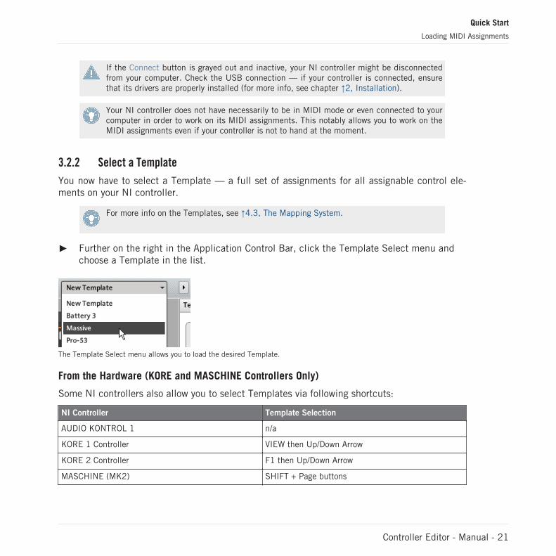
3.2.2 Select a Template
You now have to select a Template — a full set of assignments for all assignable control ele-ments on your NI controller.
For more info on the Templates, see ↑4.3, The Mapping System.
► Further on the right in the Application Control Bar, click the Template Select menu andchoose a Template in the list.
The Template Select menu allows you to load the desired Template.
From the Hardware (KORE and MASCHINE Controllers Only)
Some NI controllers also allow you to select Templates via following shortcuts:
NI Controller Template Selection
AUDIO KONTROL 1 n/a
KORE 1 Controller VIEW then Up/Down Arrow
KORE 2 Controller F1 then Up/Down Arrow
MASCHINE (MK2) SHIFT + Page buttons
Quick Start
Loading MIDI Assignments
Controller Editor - Manual - 21

NI Controller Template Selection
MASCHINE MIKRO (MK2) SHIFT + Left/Right Arrow buttons
RIG KONTROL 3 n/a
TRAKTOR KONTROL S4 n/a
TRAKTOR KONTROL S2 n/a
TRAKTOR KONTROL X1 n/a
TRAKTOR KONTROL F1 n/a
More info on this in the respective controller-specific chapters, later in this manual.
Either way, the Template will automatically be loaded upon selection and its assignments willbe displayed. You can now control the new target from your NI controller.
Each assignment is recalled at the last state of use: the software remembers the last value foreach of the control elements assigned in this Template. If it’s the first time that you load aTemplate, all assignments are at their default value.
RIG KONTROL 3 and TRAKTOR KONTROL S2: You can skip the following sections and di-rectly go to ↑3.2.5, Ready to Go?.
3.2.3 Select a Knob Page
RIG KONTROL 3 and TRAKTOR KONTROL S2: There are no Knob Pages available forthese controllers. Hence, you can skip this section.
Within each Template, some (or all) of the control elements of your NI controller can have mul-tiple assignments, organized into Knob Pages. In the Hardware area, these control elements areindicated by an orange frame surrounding them.
Quick Start
Loading MIDI Assignments
Controller Editor - Manual - 22

The orange frame representing the Knob Page in the Hardware area for the MASCHINE controller (detail).
At any time there is one active Knob Page, i.e. one active subset of assignments for these spe-cific control elements.
For more info on the Knob Pages, see ↑4.3, The Mapping System.
Thus, let’s select a particular Knob Page of assignments for loading:
► To select a Knob Page, click the Knob Page menu (the orange menu above the orangeframe in the picture above) and select the desired Knob Page in the list.
TRAKTOR KONTROL S4: the S4 Overview
Due to its great size and number of control elements, the TRAKTOR KONTROL S4 is dividedinto three parts in the Controller Editor: left Deck, Mixer, and right Deck. Thus, before select-ing any Knob Page on this controller, you first have to choose a specific part for displaying.This is done via the S4 Overview, at the top left corner of the Hardware area:
Use the little S4 Overview to select the desired Deck.
You have two Knob Pages at your disposal for each Deck A–D. To select a specific Knob Page:
Quick Start
Loading MIDI Assignments
Controller Editor - Manual - 23

1. Click the left or right Deck in the S4 Overview.2. Click the Knob Page menu (the orange menu above the orange frame) and select the de-
sired Knob Page in the list.
There is a similar Overview available for the TRAKTOR KONTROL S2, which however doesnot offer any Knob Pages. Nevertheless, we will make use of the S2 Overview when select-ing particular control elements (see ↑3.3, Modifying an Assignment).
From the Hardware
You can also select Knob Pages from your NI controller:
NI Controller # of Available Knob Pages Knob Page Switch/Selection
AUDIO KONTROL 1 2 Left button
KORE Controllers Unlimited Up and Down Arrow buttons
MASCHINE (MK2) Unlimited Page buttons
MASCHINE MIKRO (MK2) Unlimited Left/Right Arrow buttons
RIG KONTROL 3 n/a
TRAKTOR KONTROL S4 2 for each Deck A–D DECK C/D then SHIFT
TRAKTOR KONTROL S2 n/a
TRAKTOR KONTROL X1 2 SHIFT
TRAKTOR KONTROL F1 2 SHIFT
More info on this in the controller-specific chapters, later in this manual.
3.2.4 Select a Pad Page (MASCHINE Controller Family Only)
The sixteen pads of your MASCHINE (MK2) or MASCHINE MIKRO (MK2) controller can op-tionally have multiple assignments, too. These are as well organized into pages: the Pad Pages.The Pad Page feature can be activated at the Template level: you can have some Templateswithout Pad Pages (i.e. with one assignment each pad) and some other with Pad Pages (i.e.with several assignments for each pad).
Quick Start
Loading MIDI Assignments
Controller Editor - Manual - 24
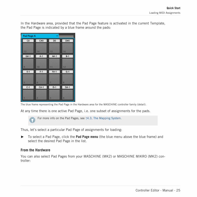
In the Hardware area, provided that the Pad Page feature is activated in the current Template,the Pad Page is indicated by a blue frame around the pads:
The blue frame representing the Pad Page in the Hardware area for the MASCHINE controller family (detail).
At any time there is one active Pad Page, i.e. one subset of assignments for the pads.
For more info on the Pad Pages, see ↑4.3, The Mapping System.
Thus, let’s select a particular Pad Page of assignments for loading:
► To select a Pad Page, click the Pad Page menu (the blue menu above the blue frame) andselect the desired Pad Page in the list.
From the Hardware
You can also select Pad Pages from your MASCHINE (MK2) or MASCHINE MIKRO (MK2) con-troller:
Quick Start
Loading MIDI Assignments
Controller Editor - Manual - 25

NI Controller # of Available Pad Pages Pad Page Selection
MASCHINE (MK2) 8 (if feature activated) Group buttons A–H
MASCHINE MIKRO (MK2) 8 (if feature activated) GROUP + pads 9–16
Fore more info on the available commands on your controller, see chapter ↑5, Using YourMASCHINE Controller, ↑7, Using Your MASCHINE MIKRO Controller, ↑7, Using Your MA-SCHINE MIKRO Controller, or ↑8, Using Your MASCHINE MIKRO MK2 Controller.
3.2.5 Ready to Go?
If you only plan to use this Template (and Knob Page / Pad Page) as it is, i.e. without modify-ing any of its MIDI assignments, you’re done! As you may have noticed, you can do all thisfrom within your MASCHINE (MK2), MASCHINE MIKRO (MK2) or KORE Controller — this be-ing of course the preferred way for any live situation. If you used the Controller Editor, you canclose the application now: the corresponding NI background service will take care of everythingand you can start using your NI controller as a MIDI remote control right away!
3.3 Modifying an Assignment
Now, if you want to modify some of the assignments stored in the selected Template (and pos-sibly one of its Knob Pages and/or Pad Pages), continue with these few more steps:
1. TRAKTOR KONTROL S2/S4 only: In the S2/S4 Overview at the top left, click the part ofthe controller (left Deck, Mixer, or right Deck) containing the control element whose as-signment you want to edit.
2. Select the desired control element. You can do this in two ways: In the Controller Editor,click the control element within the hardware representation (a double-click on the con-trol element directly brings the Inspector’s Assign page to the front for faster editing, seenext step). You can also [Shift]-click several control elements of the same type (or clickand drag a rectangle) to select them. Or, on your NI controller, touch the control element
Quick Start
Loading MIDI Assignments
Controller Editor - Manual - 26

(for this, the Touch Select option must be enabled in File > Preferences > General — thisis the case by default).Either way, the control elements selected for editing get surrounded by the red SelectionFrame in the Controller Editor window:
3. In the Inspector (the right part of the Controller Editor interface), click the Assign tab:
The Assign page opens up and displays all assignments’ properties for the selected con-trol element(s).
4. Modify the assignment’s properties according to your needs: at the top, you can edit thename of the assignment, and below, all MIDI properties like the type of MIDI message tobe sent, the MIDI channel to use, and so on. The assignment’s details will differ depend-ing on the type of MIDI message you choose.
→ That’s it! Now the corresponding control element on your NI controller triggers the MIDImessage that you just defined.
Quick Start
Modifying an Assignment
Controller Editor - Manual - 27
3.4 Organizing Your Assignments
Thanks to its powerful mapping system, the Controller Editor lets you organize your assign-ments as you like. You can define various Knob Pages, Pad Pages and Templates to addressvarious situations: For example, you could define different Knob Pages to control different in-struments in your setup. Furthermore, you could prepare different Templates for differentsongs in your live performance, with all necessary Pad Pages and Knob Pages inside.
3.4.1 Displaying the Lists of Templates and Pages
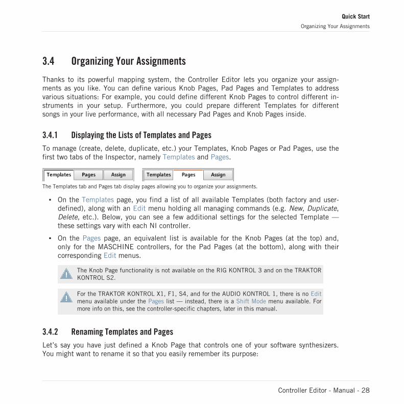
To manage (create, delete, duplicate, etc.) your Templates, Knob Pages or Pad Pages, use thefirst two tabs of the Inspector, namely Templates and Pages.
The Templates tab and Pages tab display pages allowing you to organize your assignments.
▪ On the Templates page, you find a list of all available Templates (both factory and user-defined), along with an Edit menu holding all managing commands (e.g. New, Duplicate,Delete, etc.). Below, you can see a few additional settings for the selected Template —these settings vary with each NI controller.
▪ On the Pages page, an equivalent list is available for the Knob Pages (at the top) and,only for the MASCHINE controllers, for the Pad Pages (at the bottom), along with theircorresponding Edit menus.
The Knob Page functionality is not available on the RIG KONTROL 3 and on the TRAKTORKONTROL S2.
For the TRAKTOR KONTROL X1, F1, S4, and for the AUDIO KONTROL 1, there is no Editmenu available under the Pages list — instead, there is a Shift Mode menu available. Formore info on this, see the controller-specific chapters, later in this manual.
3.4.2 Renaming Templates and Pages
Let’s say you have just defined a Knob Page that controls one of your software synthesizers.You might want to rename it so that you easily remember its purpose:
Quick Start
Organizing Your Assignments
Controller Editor - Manual - 28

1. In the Pages list, double-click the Knob Page that you just defined (let’s say Knob Page3). Its name gets highlighted.
2. Type a new name for this Knob Page (for example, “Absynth Lead”) and press [Enter] onyour computer keyboard to confirm the change:
3.4.3 Re-ordering Templates and Pages
You may want to put this Knob Page at the top of the list, e.g. if you plan to use this synthesiz-er at first in your song and want to have direct access to its parameters from your Controller:
1. Click the Knob Page Absynth Lead in the list, hold the mouse button depressed and dragyour mouse toward the top of the list. An insertion line appears to show you the positionwhere the Knob Page is going to be moved to.
2. When the insertion line reaches the top of the list (or the desired insertion position, wher-ever it is), release the mouse button. The Knob Page “Absynth Lead” takes its new posi-tion in the list.
The Knob Pages for the TRAKTOR KONTROL X1, F1, S4, and for the AUDIO KONTROL 1cannot be reordered.
This way-of-doing can also be applied to the Pad Pages (at the bottom of this Pages page, onlyfor the MASCHINE controllers) as well as to the Templates (on the Templates page). The Editmenus offer more managing features — you will find all details later in this manual (mainlysections ↑4.2.4, Inspector, ↑17.5, The Inspector, and ↑17.6, MIDI Message Parameters). Fora detailed description of the mapping system, please refer to section ↑4.3, The Mapping Sys-tem.
Quick Start
Organizing Your Assignments
Controller Editor - Manual - 29
3.5 Saving and Loading Templates
Once you have defined a set of assignments that fits your needs, you have the possibility tosave it.
Actually, you don’t necessarily need to save it, since the Controller Editor automatically savesany changes made to the Template on which you are working (and its included Knob Pages,Pad Pages and single assignments). So if you only plan to use this Template later on the samecomputer, you can quit the Controller Editor, the Template will be recalled with all modifica-tions next time you switch your NI controller to MIDI mode and select this Template again (ifyou switched to another Template in the meanwhile).
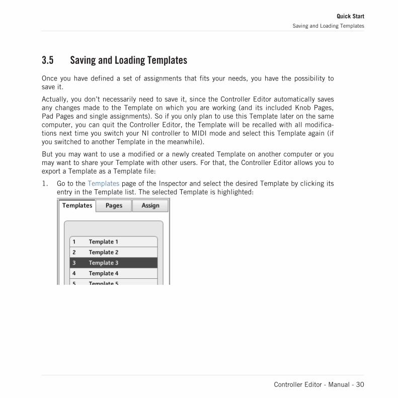
But you may want to use a modified or a newly created Template on another computer or youmay want to share your Template with other users. For that, the Controller Editor allows you toexport a Template as a Template file:
1. Go to the Templates page of the Inspector and select the desired Template by clicking itsentry in the Template list. The selected Template is highlighted:
Quick Start
Saving and Loading Templates
Controller Editor - Manual - 30

2. Below the list, click the Edit menu and select Save As:
3. In the Save template dialog that opens, choose the destination and type the name of theTemplate file to be exported. Please note that the filename that you choose can be differ-ent from the Template’s name inside the Controller Editor. Once this is done, click Saveto export the file and you’re done.
Template filenames have various extensions depending on the affected NI controller.Please see ↑4.3.4, Templates for a list of filename extensions.
You can now transfer this Template file to another computer, share it with a friend, etc.
On the other hand, as you would expect, the Controller Editor also allows you to load a Tem-plate file. To do this:
1. In the Templates page of the Inspector, click the Edit menu, select Append and chooseOpen. An Open template dialog appears that lets you navigate through your file system onyour computer and choose a Template file to import.
2. Select the desired Template file and click Open. The Template is loaded and appended toyour Template list.
The Controller Editor provides many factory Templates for use with various MIDI targets.Please refer to the Controller Editor Template Documentation to know how to use them!
Quick Start
Saving and Loading Templates
Controller Editor - Manual - 31

4 Basic Concepts
In this chapter we will introduce you to the basics of the Controller Editor. You might have al-ready checked the previous chapter, which gives you a first idea of how to use the ControllerEditor. Here, we will approach the system in a more general way.
4.1 How the Controller Editor Works
The Controller Editor allows you to define the links between your NI controller and the audioapplications running on your computer or your external MIDI devices. It lets you decide howyour actions on the NI controller will be interpreted. For this purpose, the Controller Editor im-plements a powerful mapping system allowing you to define as many MIDI assignments as youwant for each knob, pad, encoder, fader, or button available on your NI controller.
The Controller Editor works in conjunction with a small background service installed on yourcomputer during the Controller Editor installation procedure. This background service takescare of all communication matters between your NI controller and your MIDI-capable targets,both on the software side and on the hardware side. It stays alive even if you close the Control-ler Editor application. This especially means that you don’t necessarily need to have the Con-troller Editor open on your computer to use your NI controller as a MIDI remote control! Youcan select and/or tweak your assignments in the Controller Editor and then quit the application— the assignments (and Templates / Knob Pages / Pad Pages, see below) stay active thanks tothis small background service. Thus, the Controller Editor can be seen as an assignment editor:use it to check or edit your assignments.
4.2 Overview of the User Interface
Let us have a closer look at the Controller Editor user interface now. When you start the Con-troller Editor, you can see something like this:
Basic Concepts
How the Controller Editor Works
Controller Editor - Manual - 32

The Controller Editor user interface: the big view (Windows version pictured, with the MASCHINE MK2 controller in theHardware area)
The user interface is divided into four main areas, namely:
(1) Application Menu Bar
(2) Application Control Bar
(3) Hardware area
(4) Inspector
Basic Concepts
Overview of the User Interface
Controller Editor - Manual - 33

In the following sections you will find a brief introduction to all areas of the software and theircorresponding control elements. For a detailed description of each of these elements, pleaserefer to chapter ↑17, Reference.
4.2.1 Application Menu Bar
At the top of the Controller Editor window (or at the top of your computer screen on Mac OS X),the Application Menu Bar is similar to the one found with most applications on your operatingsystem. Here it consists of three menus (File, View, and Help) controlling the general functionsof the software:
The Application Menu Bar (Windows version pictured)
4.2.2 Application Control Bar
Right under the Application Menu Bar, the Application Control Bar holds menus and buttonscontrolling the overall mapping system:
The Application Control Bar
From left to right, we have the following controls:
(1) Device menu: Allows you to switch to another Controller and states which Controller you arecurrently working with.
(2) Connect button: Allows you to “call” your hardware — in other words, to switch it to MIDImode and connect it to the Controller Editor, in case it is currently connected to its dedicatedsoftware.
(3) Template Select menu: Allows to select the desired Template (Templates are explained inthe next section, ↑4.3, The Mapping System).
(4) Minimize/Expand View button (the little arrow): Switches between two views of the ControllerEditor, by hiding/showing the Hardware area.
Basic Concepts
Overview of the User Interface
Controller Editor - Manual - 34

(5) MIDI Activity indicator: Shows any incoming/outgoing MIDI data.
(6) NI Logo: Opens the About screen.
4.2.3 Hardware Area
Below the previous two bars, the left (and biggest) part of the user interface holds the Hard-ware area. The Hardware area basically represents your NI controller and all its control ele-ments — most of them are freely assignable to MIDI messages.
If the Controller Editor is reduced to a small column on your screen, it means that theHardware area is hidden. To show it, click the Minimize/Expand View button (the little ar-row) in the Application Control Bar above.
The Controller depicted in the Hardware area depends on the device selected in the Devicemenu located in the Application Control Bar (see above).
► Click an assignable control element in the Hardware area to edit its assignment.
Compared to your real NI controller, the Hardware area holds a few additional graphical ele-ments:
▪ Every control element that can be assigned to a MIDI message comes with a Label Fieldwhich displays a name describing by default its current assignment).
Pairs of mini buttons in the Hardware area: If mini buttons are not selected when you clickthem, click their Label Field instead!
▪ A red Selection Frame highlights the currently selected control element(s).
▪ An orange Knob Page menu allows you to select a particular Knob Page of assignments(see section ↑4.3, The Mapping System for more info on this). The Knob Page area, de-noted by an orange frame, holds the control elements affected by the Knob Page selectionin the Knob Page menu.
The Knob Page feature is not available on the RIG KONTROL 3 and on the TRAKTOR KON-TROL S2.
Basic Concepts
Overview of the User Interface
Controller Editor - Manual - 35

▪ MASCHINE controllers only: If the Pad Page feature is activated, an additional blue PadPage menu allows you to select a particular page of assignments for the pads. The blueframe highlights the Pad Page area, which holds the control elements included in the PadPages — namely the pads. Please refer to section ↑4.3.3, Pad Pages (MASCHINE Con-troller Family Only) for more info on this.
▪ TRAKTOR KONTROL S2/S4 only: At the upper left corner, the little S2/S4 Overview al-lows you to select a specific part of your controller for displaying and editing (left Deck,Mixer, or right Deck). The Hardware area displays the part of the S2/S4 that you selectedhere.
You will find a detailed description of each Hardware area / NI controller and its assignablecontrol elements in the respective controller-specific chapters, later in this manual.
4.2.4 Inspector
At the right of the Hardware area, the Inspector is the control tower of your mapping system.There, you can precisely define what has to be done on your target when you press, turn, ormove anything on your NI controller. Moreover, you can organize all your assignments intoKnob Pages, Pad Pages (on the MASCHINE controllers) and Templates. Section ↑17.5, The In-spector will give you a detailed description of all what you can do with the Inspector.
The Inspector is divided into three pages, each of them controlling a specific part of the map-ping scheme: the Templates page, the Pages page, and the Assign page.
The Templates Page
The Templates page allows you to manage your Templates. It shows a list of available Tem-plates along with a few editing functions.
A Template holds a whole mapping configuration for all control elements of your NI control-ler. For more info, see ↑4.3.4, Templates below.
Basic Concepts
Overview of the User Interface
Controller Editor - Manual - 36

The Templates page in the Inspector (here for the MASCHINE controller)
The Templates page holds the following elements, from top to bottom:
(1) Template list: Shows all available Templates with, for each Template, an index number (noteditable) and a name (editable). There, you can select a Template for editing by clicking itsname, and modify its name by double-clicking it (you can also select a Template via the Tem-plate Select menu in the Application Control Bar, or possibly from your NI controller).
(2) Template Edit menu and Factory Templates menu: The Edit menu provides you with editingfunctions like New, Save As, etc. The Factory Templates menu allows you to load factory Tem-plates.
(3) Template Properties area: Gives you access to the properties of the Template that is current-ly selected in the upper Template list.
There is no Template Properties area for the TRAKTOR KONTROL X1/F1/S2.
Basic Concepts
Overview of the User Interface
Controller Editor - Manual - 37
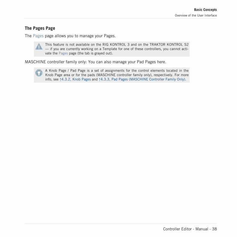
The Pages Page
The Pages page allows you to manage your Pages.
This feature is not available on the RIG KONTROL 3 and on the TRAKTOR KONTROL S2— if you are currently working on a Template for one of these controllers, you cannot acti-vate the Pages page (the tab is grayed out).
MASCHINE controller family only: You can also manage your Pad Pages here.
A Knob Page / Pad Page is a set of assignments for the control elements located in theKnob Page area or for the pads (MASCHINE controller family only), respectively. For moreinfo, see ↑4.3.2, Knob Pages and ↑4.3.3, Pad Pages (MASCHINE Controller Family Only).
Basic Concepts
Overview of the User Interface
Controller Editor - Manual - 38

The Pages page in the Inspector for the MASCHINE controller.
The Pages page holds the following elements:
(1) Page list: Shows a list with all available Knob Pages with, for each of them, an index num-ber (not editable) and a name (editable). There, you can select a Knob Page for editing byclicking its name, and modify its name by double-clicking it. On the MASCHINE controllersand KORE Controllers, you can rearrange the page order via drag&drop. You can also select aKnob Page via the orange Knob Page menu in the Hardware area, or possibly from your NI con-troller.
Basic Concepts
Overview of the User Interface
Controller Editor - Manual - 39

(2) Knob Page Edit menu: Provides you with editing functions like New, Duplicate, etc.
For the TRAKTOR KONTROL X1/F1/S4 and the AUDIO KONTROL 1, this Edit menu is re-placed with a Shift Mode menu with the two options Gate and Toggle allowing you to choosethe behavior of the SHIFT button when switching between Knob Pages from your controller.For more info on this, see the controller-specific chapters, later in this manual.
(3) Enable Pad Pages button: Activates/deactivates the Pad Page feature. If the Pad Page fea-ture is deactivated, the rest of the area is grayed out and won’t react to user action.
(4) Pad Page list: Shows a list with all available Pad Pages with, for each of them, an indexnumber (not editable) and a name (editable). There, you can select a Pad Page for editing byclicking its name, and modify its name by double-clicking it. You can rearrange the page ordervia drag&drop. You can also select a Pad Page via the Pad Page menu above the pads in theHardware area, or with the Group buttons labeled A to H, both in the Hardware area and onyour MASCHINE controller.
(5) Pad Page Edit menu: Provides you with editing functions like New, Duplicate, etc.
Elements 3 to 5 are available if you are working on the assignments for either of the MA-SCHINE controllers.
The Assign Page
The last page in the Inspector is the Assign page. This is where you specify all details of theassignment for a particular control element. This page shows the properties of the currently se-lected control element:
Basic Concepts
Overview of the User Interface
Controller Editor - Manual - 40

The Assign page in the Inspector.
The Assign page shows different properties depending on the type of element currently select-ed.
(1) Description area: This area is common to all control elements. It shows the following infor-mation about the currently selected control element: The index number and the name of theKnob Page or Pad Page of the selected control element (this is empty for the elements not in-cluded in a Knob Page / Pad Page). The element description (not editable) and its name (edit-able).
(2) Definition area: Defines the MIDI assignment properties for the current control element.Please refer to section ↑17.5.3, Assign Page in the reference chapter for more info.
Basic Concepts
Overview of the User Interface
Controller Editor - Manual - 41

4.3 The Mapping System
Whatever you do on your NI controller, the Controller Editor translates it into a MIDI messagethat is then sent to the desired MIDI port — this is what the Controller Editor is all about:mapping human actions to MIDI events.
The Controller Editor’s mapping system is structured in a way that allows you to efficiently or-ganize your assignments. This makes the whole mapping process a lot easier and informs youabout what will happen whenever you actuate a control element on your NI controller. The nextparagraphs will introduce you to some basic concepts.
4.3.1 Assignments
An assignment defines which MIDI event is triggered by a particular control element. AvailableMIDI event types are “MIDI Note,” “MIDI CC,” etc. Every action on a control element is trans-lated into one MIDI event, the corresponding assignment defines the rules of that translation.
Depending on the type of control element (button, knob, pad, fader, encoder, pedal input,footswitch…), the available assignments differ. For more details about all available assign-ments for each type of control, please refer to section ↑17.6, MIDI Message Parameters.
4.3.2 Knob Pages
Knob Pages are not available on the RIG KONTROL 3 and on the TRAKTOR KONTROL S2.
For some of the control elements, you can have multiple assignments, organized in pagescalled Knob Pages. Those particular control elements are located in the Knob Page area (theorange frame in the Hardware area, see section ↑4.2.3, Hardware Area above). A Knob Page isa set of assignments for all control elements in this Knob Page area. One Knob Page can beselected (and loaded) at a time.
On the KORE Controller, the Knob Pages are the MIDI equivalent to the Control Pages inthe KORE 2 software.
Basic Concepts
The Mapping System
Controller Editor - Manual - 42
You can switch the available Knob Pages (either built-in or user-defined) via the Knob Pagemenu in the Hardware area or via the Pages list in the Inspector (see section ↑4.2, Overview ofthe User Interface above for a brief description of the interface). You can do it as well fromyour NI controller — more on this in the respective chapters describing the use of each NI con-troller.
When you select another Knob Page, all assignments for the control elements in the KnobPage area are updated accordingly. All Knob Pages are stored as an editable list on the Pagespage of the Inspector (for detailed information about the Inspector, see ↑17.5, The Inspector).
4.3.3 Pad Pages (MASCHINE Controller Family Only)
On the MASCHINE (MK2) and MASCHINE MIKRO (MK2) controllers, you also have access toa similar (but optional) paging system dedicated to the pads: the Pad Pages. The Pad Pageswork like the Knob Pages explained above, but they affect the sixteen pads instead of the con-trol elements in the Knob Page area.
The number of Pad Pages is limited to eight. One Pad Page can be selected at a time.
The Pad Pages can be activated or deactivated, depending on your needs, via the Enable PadPages button in the Inspector’s Assign page. If activated, you can switch the available Pad Pa-ges via the Pad Page menu or the eight Group buttons in the Hardware area, or via the PadPage list in the Inspector. Again, you can do it as well from your NI controller, via the sameGroup buttons (labeled from A to H).
When you select another Pad Page, all assignments for the sixteen pads are updated accord-ingly. The eight available Pad Pages are stored as an editable list on the Pages page in theInspector (you will find all details about the Inspector in section ↑17.5, The Inspector).
4.3.4 Templates
A Template holds a mapping configuration for all control elements on your NI controller, in-cluding the Knob Pages and Pad Pages that might exist. One Template can be selected at atime. The Template also determines if the generated MIDI events have to be sent to the inter-nal MIDI port (to access an application listening to MIDI on your computer) or to the externalMIDI port (to access an external MIDI-capable device) — only for Controllers that are equippedwith MIDI ports of course. Switching between different Templates can be used, for example, toaddress different applications on your computer or different hardware instruments.
Basic Concepts
The Mapping System
Controller Editor - Manual - 43

The Template contains all Knob Page/Pad Page data, the list of Knob Pages/Pad Pages and theindex of the last selected Knob Page/Pad Page. The Template also stores the last state of eachcontrol element.
The Templates can be stored as distinct files on your computer. These files have the followingextensions:
NI Controller Template file extension
MASCHINE .ncm
MASCHINE MK2 .ncm2
MASCHINE MIKRO .ncmm
MASCHINE MIKRO MK2 .ncmm2
KORE Controllers .nck
TRAKTOR KONTROL X1 .nckx1
TRAKTOR KONTROL F1 .nckf1
TRAKTOR KONTROL S4 .ncks4
TRAKTOR KONTROL S2 .ncks2
RIG KONTROL 3 .ncg
AUDIO KONTROL 1 .ncak1
You can switch among the available Templates (either built-in or user-defined) via the Tem-plate Select menu in the Application Control Bar or via the Template list in the Inspector. Thiscan also be done from some NI controllers — more on this in the respective chapters describ-ing the use of each NI controller.
When you select another Template, all assignments for all control elements of the interface areupdated accordingly, including the Knob/Pad Pages. All Templates are stored as an editablelist on the Templates page in the Inspector (see section ↑17.5, The Inspector).
The Controller Editor provides many factory Templates for use with various MIDI targets.Please refer to the Controller Editor Template Documentation to know how to use them!
Basic Concepts
The Mapping System
Controller Editor - Manual - 44
4.3.5 Configuration
For each NI controller, the working set of data contains the current list of Templates, all dataof the Templates in the list, and the index of the currently selected Template.
The group of all data sets can be stored as a single Configuration file on your computer. Thistype of file has the extension “.ncc.”
4.4 To sum up…
By utilizing your NI controller and the Hardware Service (the Controller Editor and the NI back-ground service) you can remote-control any MIDI target. The Hardware Service was designed ina way that allows you to forget its presence in a live situation: after having configured your as-signments, you can rely on your NI controller to control everything you need during your per-formance. Triggering MIDI hardware devices and applications in various ways, switching in realtime to other sets of assignments (except for the RIG KONTROL 3)… all this can be done di-rectly from your NI controller.
Actually, the only thing that you can not do from the Controller is modify your assignments…For that, you will need to use the Controller Editor! But thanks to the powerful mappingscheme using Templates, Knob Pages and Pad Pages, which is partly mirrored on your NI con-troller, you can prepare as many assignments as you want and recall them instantly during yourlive performance.
In the next chapters, we will show you how to use your NI controller(s) with the assignmentsdefined within the Controller Editor.
Basic Concepts
The Mapping System
Controller Editor - Manual - 45

5 Using Your MASCHINE Controller
In this chapter, we will focus on what’s happening on your MASCHINE controller. By readingthis, you will learn:
▪ How to use the basic controls on your controller for navigating through the MIDI mappingsystem.
▪ The list of all assignable control elements on your controller.
▪ How the various luminous elements give you some important information about theirstate.
▪ How to use the powerful displays of your MASCHINE controller in MIDI mode.
To enjoy full functionality of your NI controller as a MIDI remote control, especially con-cerning some control elements’ state and LED behavior, you need to tell your NI controllerwhat is the current state of the parameter in the MIDI target. You can do this by setting upMIDI feedback channels coming from your MIDI target back to your NI controller. This way,your controller will always stay up-to-date with the current parameter values in your targetsoftware/hardware. For more info on how to configure these MIDI feedback channels,please refer to your target software/hardware’s documentation.
5.1 Basic Controls
This section shows you the commands available on your MASCHINE controller for basic tasks:switching between MIDI mode and MASCHINE mode, and selecting sets (Templates) and sub-sets (Knob Pages, Pad Pages) of MIDI assignments.
All these actions can of course be done via the Controller Editor user interface — see chap-ter ↑3, Quick Start for example. Nevertheless, using your NI controller instead can be veryhandy in a live situation!
Using Your MASCHINE Controller
Basic Controls
Controller Editor - Manual - 46

Selection Command
MIDI/MA-SCHINE mode
SHIFT +CONTROL
Templates SHIFT +Page but-tons
Knob Pages Page but-tons
Pad Pages
(if activated)
Groupbuttons
Display mode SHIFT +Buttons1–8
For more info on Templates, Knob Pages, and Pad Pages, see ↑4.3, The Mapping System.
Using Your MASCHINE Controller
Basic Controls
Controller Editor - Manual - 47

For more info on the display modes, see ↑5.4, The Displays. There you will also learn an-other way to select and load Templates and Knob Pages from your controller.
When your MASCHINE controller is in MIDI mode, its SHIFT button is dimly lit.
Adjusting Settings for your Controller
You can adjust various settings for your MASCHINE controller by entering its Settings displaymode or by going to File > Preferences > Controller. See ↑5.4.7, Settings Display Mode formore info.
5.2 Assignable Control Elements
If you selected the MASCHINE controller in the Device menu of the Application Control Bar,this is what the Hardware area looks like:
Using Your MASCHINE Controller
Assignable Control Elements
Controller Editor - Manual - 48

The Hardware area representing the MASCHINE controller.
In this Hardware area, you will notice the Knob Page menu and its associated Knob Page area(orange frame), the Pad Page menu and its associated Pad Page area (blue frame), and the redSelection Frame on the currently selected control element (pad 10 in the picture above).
The MASCHINE controller holds the following areas:
The names that you see on many control elements only refer to their original function in theMASCHINE software. We use these names here only to describe the interface!
Using Your MASCHINE Controller
Assignable Control Elements
Controller Editor - Manual - 49

(1) Page buttons and buttons around: In the top left part, you find a set of eight buttons arrangedinto four rows of two buttons. From these eight buttons, six are freely assignable (CONTROLand STEP, BROWSE and SAMPLING, SNAP (F1), and AUTO WRITE (F2)) and two have spe-cial functions: the left and right Page buttons (see previous section).
(2) MASTER area: The MASTER area holds four freely assignable control elements (three knobsand one button).
(3) GROUPS area: The GROUPS area contains eight buttons labeled from A to H: the Group but-tons. If you activated the Enable Pad Pages button in the Pages page of the Inspector, thesebuttons allow you to select the desired page of assignments for the pads (see ↑4.3.3, Pad Pa-ges (MASCHINE Controller Family Only)). If you didn’t activate the Pad Pages, these eight but-tons are freely assignable to MIDI events.
(4) TRANSPORT area: The TRANSPORT area contains eight buttons. Seven of them are freelyassignable: RESTART (LOOP), Previous, Next, GRID, PLAY, REC, and ERASE. The last one,SHIFT, is a special button (see previous section). Therefore, this button cannot be assigned inthe Controller Editor.
(5) Knob Page area: The Knob Page area holds a set of eight buttons and eight knobs, with thebuttons being placed above and the knobs below the two displays, respectively. These sixteencontrol elements are freely assignable. The Knob Page area is indicated by an orange frameand headed by the Knob Page menu.
The buttons and knobs in the Knob Page area can also have other functions according tothe display mode that is currently active. See ↑5.4, The Displays for more on this.
(6) PADS area: The PADS area shows a column of eight freely assignable buttons (namelySCENE, PATTERN, PAD MODE (KEYBOARD), NAVIGATE, DUPLICATE, SELECT, SOLO, andMUTE) as well as a square of sixteen freely assignable pads. If you activated the Enable PadPages button in the Pages page of the Inspector, a Pad Page area (indicated by the blueframe) groups the pads together and is headed by the Pad Page menu.
To Sum Up…
All control elements on your MASCHINE controller are freely assignable to MIDI events (withthe limitations due to the type of control element), with the following exceptions:
▪ The Page buttons and the SHIFT button have a predefined function (see previous sec-tion).
Using Your MASCHINE Controller
Assignable Control Elements
Controller Editor - Manual - 50

▪ The Group buttons, labeled A to H, are not assignable if you use the Pad Page feature —they’re used for selecting Pad Pages, see previous section. If you deactivate the Pad Pa-ges, the Group buttons are freely assignable like any other.
You can also split the controls of your controller between MIDI mode and MASCHINE modein order to control a MASCHINE plug-in instance while sending MIDI messages to the hostwith the transport controls! See ↑17.5.1, Templates Page for more info.
Assignment Parameters
The following table summarizes where to find all assignment details for each type of controlelement on your controller:
Type of Control Element Assignment Parameters
Buttons ↑17.6.2, Assignments for Buttons and the Like
Pads – Hit action ↑17.6.3, Assignments for the Pads – Hit Action
Pads – Press action ↑17.6.5, Assignments for the Pads – Press Action
Knobs ↑17.6.7, Assignments for Analog Encoders and the Like
5.3 Visual Feedback on your Controller
The fast bidirectional communication between your MASCHINE controller and the HardwareService on the software side allows status indications on your controller to be made in realtime.
Your MASCHINE controller provides you visual feedback in various ways:
▪ All buttons and pads are equipped with LEDs that inform you about the assignment stateof the control element at any time.
▪ The displays show you additional info about the assignments.
5.3.1 Buttons
The LEDs below each button can have three states: off, dimmed and bright. Their lighting be-havior depends on the type and state of the control element.
The following table indicates you the possible states for the LEDs:
Using Your MASCHINE Controller
Visual Feedback on your Controller
Controller Editor - Manual - 51

Button State LED State
Not assigned Off
Assigned – Off state Dimmed
Assigned – On state Bright
For buttons in Increment mode, the Off state corresponds to the zero value, while the Onstate corresponds to a value greater than zero. See section ↑17.6.2, Assignments for But-tons and the Like for more info on the various button modes.
Controlling the Button State
The On/Off state of each button can be controlled in two ways — internally via your actions onthe button, or remotely via MIDI feedback:
▪ In Toggle mode, both controls are enabled: both your actions on the button and the possi-bly incoming MIDI messages are taken into account to update the button and LED state.
▪ In Trigger, Gate, and Increment mode, you can choose which control mode (internal or re-mote via MIDI) you want to use. This is done via the LED On menu in the Assign page ofthe Inspector.
For more info on the button modes, LED On menu, and MIDI feedback mode, see ↑17.6.2,Assignments for Buttons and the Like.
Moreover, for the Buttons 1–8 above the displays, the particular assignment is shown withinthe displays in Knobs display mode (see section ↑5.4.2, Knobs Display Mode).
5.3.2 Pads
Here are the rules for the pads. Since the pads have two functions (they are pressure-sensi-tive), the states are indicated as follows:
▪ If the pad is not assigned, it is off.
▪ If there is an assignment for the Hit action, the pad’s LED behaves like that of a button(see previous section).
Using Your MASCHINE Controller
Visual Feedback on your Controller
Controller Editor - Manual - 52

▪ If the Hit action is not assigned but the Press action is assigned to the Note messagetype, the LED has a low brightness to show the Off state and a high brightness to showthe On state. For all other message types, the LED stays at low brightness.
5.3.3 Knobs
The assignments for the eight Knobs under the displays are indicated within the displays inKnobs display mode. If a Knob is not assigned, the display reads “OFF.”
The VOLUME, TEMPO and SWING knobs in the MASTER area have no display, but, like for allother controls, their value is shown in the displays in the Event line of the Monitor displaymode.
For more info on the various display modes on your MASCHINE controller, see next section.
5.4 The Displays
The displays on your MASCHINE controller can show different parts of your mapping configu-ration, depending on the display mode that is activated. Each display mode modifies the behav-ior of Buttons 1–8 above the displays and Knobs 1–8 below them. Learn more about the differ-ent display modes available for the MASCHINE controller in the following sections.
5.4.1 Switching Between Display Modes
First of all, to switch between display modes, press the SHIFT button on your MASCHINE con-troller and hold it. On the displays, you see something like this:
The displays on your MASCHINE controller in MIDI mode, when the SHIFT button is depressed.
Using Your MASCHINE Controller
Visual Feedback on your Controller
Controller Editor - Manual - 53

This screen allows you to select the desired display mode. On the top, you find six fields repre-senting the six display modes, from left to right: MONITOR, SETTINGS, KNOBS, PADS, PAGE,and TEMPLATE.
► To switch to any of the display modes, hold the SHIFT button and press the correspond-ing Button 3–8 above the displays.
At any time, you can press the SHIFT button again and switch to another display mode.
In the middle part of the left display, you see the name of the current Template. This is com-mon to all display modes (except the Settings display mode), so that you can always be sureabout which Template is currently selected.
Below, a message reminds you that you can switch to another Template simply by pressing thePage buttons, since you are already holding SHIFT (see ↑5.1, Basic Controls).
5.4.2 Knobs Display Mode
The Knobs display mode is probably the one you will use the most. In this mode, the displaysshow the currently loaded Knob Page, with its eight button assignments on the top row and itseight knob assignments on the bottom row:
The Knobs display mode mirrors the currently loaded Knob Page.
This display mode allows you to see which MIDI message is currently assigned to each controlelement in the loaded Knob Page. In this mode, the 16 control elements around the displays(Buttons 1–8 above and Knobs 1–8 below) trigger the MIDI messages assigned to them.
Each field mirrors the Label Field as defined in the Inspector’s Assign page for the correspond-ing control element: the name you defined there appears here — if you haven’t defined anyname for that control element yet, its label is simply its assigned MIDI message.
In the lower row, the displays additionally show the current value for each Knob. These valuescan be displayed in two views: either via numerical values (like in the picture above), or viasmall bars:
Using Your MASCHINE Controller
The Displays
Controller Editor - Manual - 54

The Knobs display mode with bars instead of numerical values.
You can switch between the two views by holding the SHIFT button and turning Knob 5:
1. Hold SHIFT (thus getting to the switching screen explained ↑5.4.1, Switching BetweenDisplay Modes).You can see the option “SHOW BARS” or “SHOW VALUES” above Knob 5 (depending onwhich view is currently selected).
2. Turn Knob 5 to select the desired view.3. Release SHIFT.
→ The new view is displayed.
Note that depending on the assignment properties for each of the Knobs, its displayed value(or bar) can either be going from 0 to 127 or from -63 to 64 (bipolar) — this second settingcan be useful for some types of controls (e.g. a stereo balance). This only affects the value/barshown on the displays — the real MIDI value will go from 0 to 127 anyway. Please refer tosection ↑17.6.7, Assignments for Analog Encoders and the Like for more info on this.
5.4.3 Pad Pages Display Mode
The Pad Pages display mode (labeled “PADS” on the displays) allows you to check the currentassignations for the pads of your MASCHINE controller, by mirroring the current Pad Page:
The Pad Pages display mode mirrors the Pad Page currently loaded.
On the left display, you find some general info about the loaded Template, Knob Page and PadPage. The right display summarizes the pads’ assignments stored in the active Pad Page.
Using Your MASCHINE Controller
The Displays
Controller Editor - Manual - 55

5.4.4 Knob Pages Display Mode
The Knob Pages display mode allows you to switch between Knob Pages:
The Knob Pages display mode allows you to switch between Knob Pages.
On the left display, you find the usual general info about the currently loaded Template, KnobPage and Pad Page.
On the right display, you see the list of your Knob Pages, as defined in the Pages list of theInspector’s Pages page.
1. Use Buttons 5 and 6 above the up and down arrows to scroll through the list and find theKnob Page you wish to load next. You can also turn Knob 5.
2. When you have it, press Button 8 (“LOAD”) to load the selected Knob Page.Actually, this functionality is already available in many ways: in the Controller Editor, you canuse the Knob Page menu (in the Hardware area) or the Pages list (in the Inspector’s Pagespage), and on the MASCHINE controller you have the Page buttons at your disposal. But theKnob Pages display mode allows you a greater control over the Knob Page selection from theMASCHINE controller:
▪ Unlike the Knob Page menu and Pages list, you don’t have to open the Controller Editorto switch to another Knob Page.
▪ Unlike the Page buttons on your controller, you can quietly choose the next Knob Page tobe loaded, even if it’s not the one right after/before the Knob Page currently loaded. Youcan check its name to remember its assignments, and you can scroll the entire list to findthe page you want.
When you reach the end of a list while scrolling, you can choose whether the selection hasto jump at the other end of the list or stay on this last item. This can be set in Preferences> General > Wrap Template and Page Lists.
Using Your MASCHINE Controller
The Displays
Controller Editor - Manual - 56
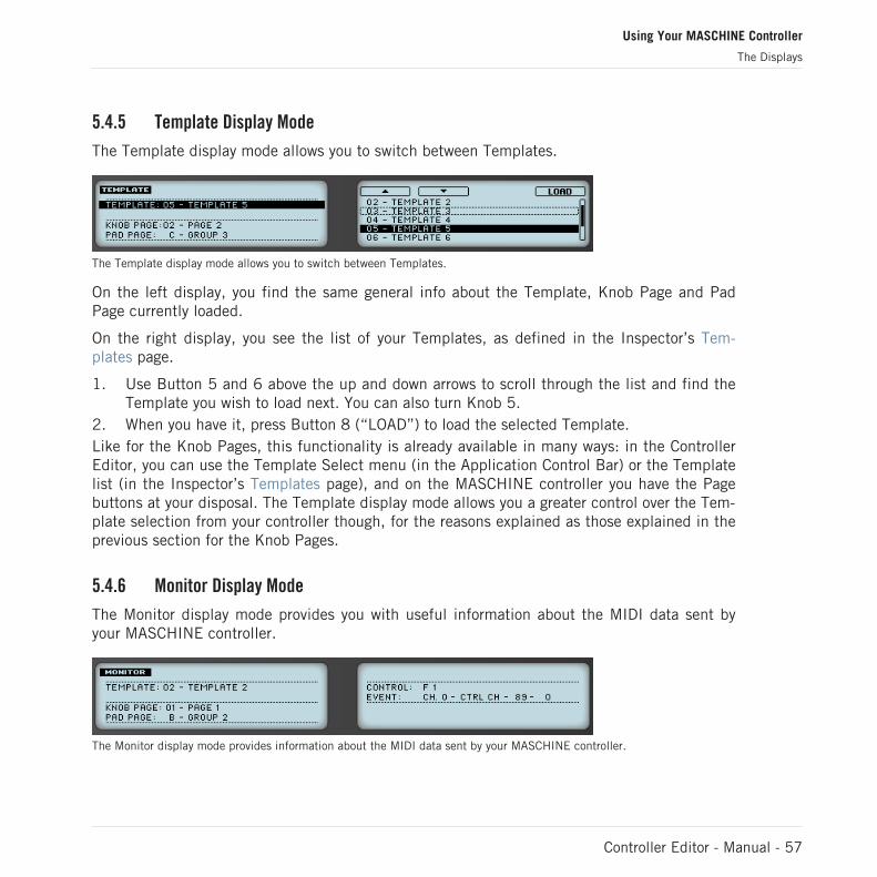
5.4.5 Template Display Mode
The Template display mode allows you to switch between Templates.
The Template display mode allows you to switch between Templates.
On the left display, you find the same general info about the Template, Knob Page and PadPage currently loaded.
On the right display, you see the list of your Templates, as defined in the Inspector’s Tem-plates page.
1. Use Button 5 and 6 above the up and down arrows to scroll through the list and find theTemplate you wish to load next. You can also turn Knob 5.
2. When you have it, press Button 8 (“LOAD”) to load the selected Template.Like for the Knob Pages, this functionality is already available in many ways: in the ControllerEditor, you can use the Template Select menu (in the Application Control Bar) or the Templatelist (in the Inspector’s Templates page), and on the MASCHINE controller you have the Pagebuttons at your disposal. The Template display mode allows you a greater control over the Tem-plate selection from your controller though, for the reasons explained as those explained in theprevious section for the Knob Pages.
5.4.6 Monitor Display Mode
The Monitor display mode provides you with useful information about the MIDI data sent byyour MASCHINE controller.
The Monitor display mode provides information about the MIDI data sent by your MASCHINE controller.
Using Your MASCHINE Controller
The Displays
Controller Editor - Manual - 57

The left display shows the usual info about the current Template, Knob Page and Pad Page.
The right display shows two lines:
▪ The Control line indicates the control element that you are currently actuating.
▪ The Event line shows the details of the MIDI event being currently sent by this control el-ement.
This display mode is very useful to monitor what’s going out of your controller, for example fordebugging purpose: if something goes wrong somewhere in your MIDI chain, you can checkhere what is actually sent by your MASCHINE controller.
5.4.7 Settings Display Mode
The Settings display mode allows you to adjust relevant parameters and provides informationabout your MASCHINE controller.
The Settings display mode provides access to parameters for your MASCHINE controller.
The settings are grouped in the left display. They are the same as in File > Preferences > Con-troller (when the MASCHINE controller is selected in the Controller menu at the top, ofcourse). The settings are:
▪ Brightness: Changes the backlight of the displays.
▪ Pad Sensitivity: Changes the sensitivity of the pads.
▪ Contrast L: Sets the contrast for the left display.
▪ Contrast R: Sets the contrast for the right display.
The right display provides you with some important information about your MASCHINE control-ler and the Hardware Service:
▪ In the upper part, you find the firmware version of your MASCHINE controller along withits serial number.
▪ Below, you see the version numbers of the NI Hardware Service and hardware drivers.
Using Your MASCHINE Controller
The Displays
Controller Editor - Manual - 58

6 Using Your MASCHINE MK2 Controller
In this chapter, we will focus on what’s happening on your MASCHINE MK2 controller. Byreading this, you will learn:
▪ How to use the basic controls on your controller for navigating through the MIDI mappingsystem.
▪ The list of all assignable control elements on your controller.
▪ How the various luminous elements give you some important information about theirstate.
▪ How to use the powerful displays of your MASCHINE MK2 controller in MIDI mode.
To enjoy full functionality of your NI controller as a MIDI remote control, especially con-cerning some control elements’ state and LED behavior, you need to tell your NI controllerwhat is the current state of the parameter in the MIDI target. You can do this by setting upMIDI feedback channels coming from your MIDI target back to your NI controller. This way,your controller will always stay up-to-date with the current parameter values in your targetsoftware/hardware. For more info on how to configure these MIDI feedback channels,please refer to your target software/hardware’s documentation.
6.1 Basic Controls
This section shows you the commands available on your MASCHINE MK2 controller for basictasks: switching between MIDI mode and MASCHINE mode, and selecting sets (Templates)and subsets (Knob Pages, Pad Pages) of MIDI assignments.
All these actions can of course be done via the Controller Editor user interface — see chap-ter ↑3, Quick Start for example. Nevertheless, using your NI controller instead can be veryhandy in a live situation!
Using Your MASCHINE MK2 Controller
Basic Controls
Controller Editor - Manual - 59
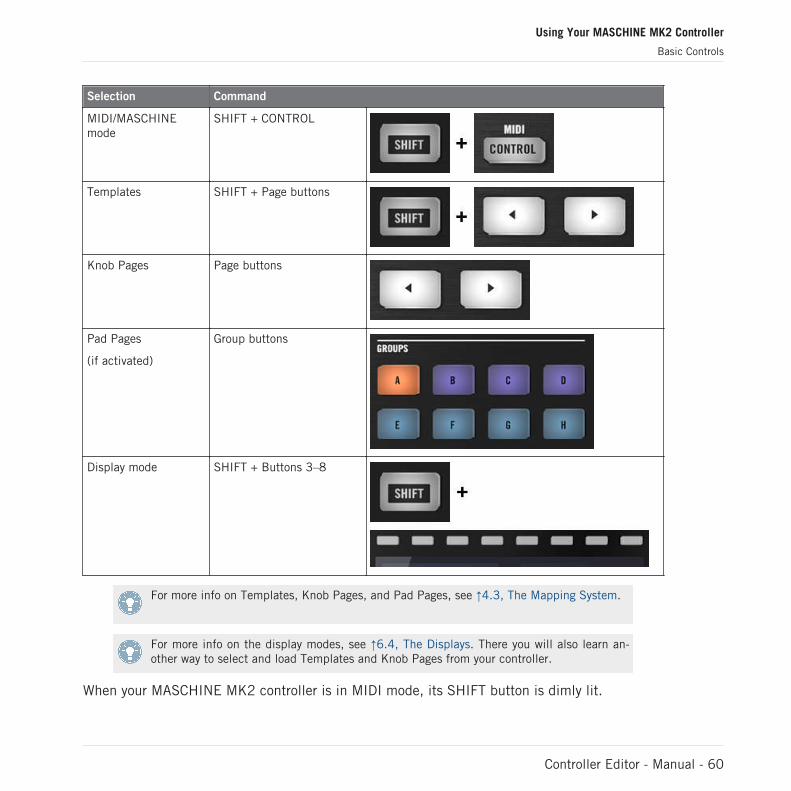
Selection Command
MIDI/MASCHINEmode
SHIFT + CONTROL
Templates SHIFT + Page buttons
Knob Pages Page buttons
Pad Pages
(if activated)
Group buttons
Display mode SHIFT + Buttons 3–8
For more info on Templates, Knob Pages, and Pad Pages, see ↑4.3, The Mapping System.
For more info on the display modes, see ↑6.4, The Displays. There you will also learn an-other way to select and load Templates and Knob Pages from your controller.
When your MASCHINE MK2 controller is in MIDI mode, its SHIFT button is dimly lit.
Using Your MASCHINE MK2 Controller
Basic Controls
Controller Editor - Manual - 60

Adjusting Settings for your Controller
You can adjust various settings for your MASCHINE MK2 controller by entering its Settingsdisplay mode or by going to File > Preferences > Controller. See ↑6.4.7, Settings Display Modefor more info.
6.2 Assignable Control Elements
If you selected the MASCHINE MK2 controller in the Device menu of the Application ControlBar, this is what the Hardware area looks like:
Using Your MASCHINE MK2 Controller
Assignable Control Elements
Controller Editor - Manual - 61

The Hardware area representing the MASCHINE MK2 controller.
In this Hardware area, you will notice the Knob Page menu and its associated Knob Page area(orange frame), the Pad Page menu and its associated Pad Page area (blue frame), and the redSelection Frame on the currently selected control element (pad 1 in the picture above).
The MASCHINE MK2 controller holds the following areas:
The names that you see on many control elements only refer to their original function in theMASCHINE software. We use these names here only to describe the interface!
Using Your MASCHINE MK2 Controller
Assignable Control Elements
Controller Editor - Manual - 62

(1) Page buttons and buttons around: In the top left part, you find a set of eight buttons arrangedinto four rows of two buttons. From these eight buttons, six are freely assignable (CONTROLand STEP, BROWSE and SAMPLING, ALL, and AUTO WR.) and two have special functions:the left and right Page buttons (see previous section).
(2) MASTER area: The MASTER area holds eight freely assignable control elements (seven but-tons and the Control encoder).
(3) GROUPS area: The GROUPS area contains eight buttons labeled from A to H: the Group but-tons. If you activated the Pad Pages button in the Pages page of the Inspector, these buttonsallow you to select the desired page of assignments for the pads (see ↑4.3.3, Pad Pages (MA-SCHINE Controller Family Only)). If you didn’t activate the Pad Pages, these eight buttons arefreely assignable to MIDI events.
(4) TRANSPORT area: The TRANSPORT area contains eight buttons. Seven of them are freelyassignable: RESTART, Previous, Next, GRID, PLAY, REC, and ERASE. The last one, SHIFT, isa special button (see previous section). Therefore, this button cannot be assigned in the Con-troller Editor.
(5) Knob Page area: The Knob Page area holds a set of eight buttons and eight knobs, with thebuttons being placed above and the knobs below the two displays, respectively. These sixteencontrol elements are freely assignable. The Knob Page area is indicated by an orange frameand headed by the Knob Page menu.
The buttons and knobs in the Knob Page area can also have other functions according tothe display mode that is currently active. See ↑6.4, The Displays for more on this.
(6) PADS area: The PADS area shows a column of eight freely assignable buttons (namelySCENE, PATTERN, PAD MODE, NAVIGATE, DUPLICATE, SELECT, SOLO, and MUTE) as wellas a square of sixteen freely assignable pads. If you activated the Enable Pad Pages button inthe Pages page of the Inspector, a Pad Page area (indicated by the blue frame) groups thepads together and is headed by the Pad Page menu.
To Sum Up…
All control elements on your MASCHINE MK2 controller are freely assignable to MIDI events(with the limitations due to the type of control element), with the following exceptions:
▪ The Page buttons and the SHIFT button have a predefined function (see previous sec-tion).
Using Your MASCHINE MK2 Controller
Assignable Control Elements
Controller Editor - Manual - 63
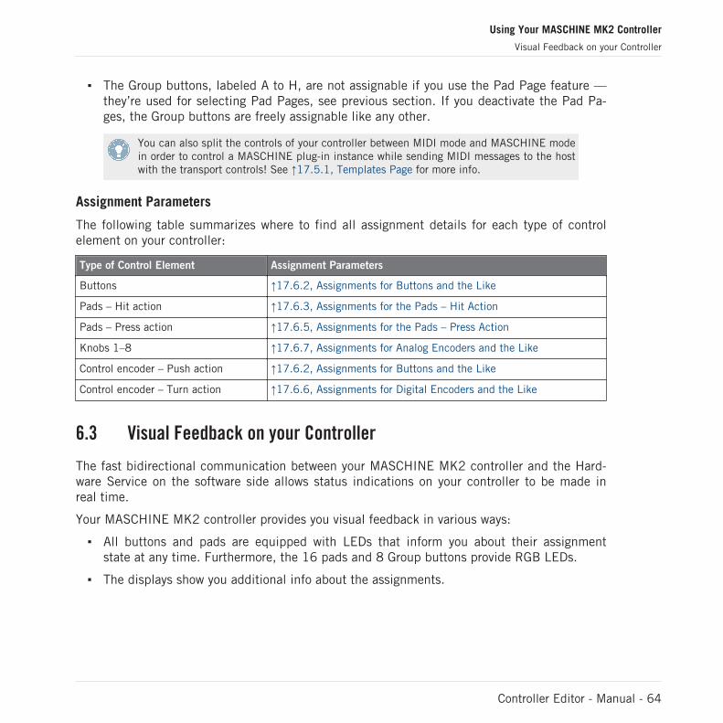
▪ The Group buttons, labeled A to H, are not assignable if you use the Pad Page feature —they’re used for selecting Pad Pages, see previous section. If you deactivate the Pad Pa-ges, the Group buttons are freely assignable like any other.
You can also split the controls of your controller between MIDI mode and MASCHINE modein order to control a MASCHINE plug-in instance while sending MIDI messages to the hostwith the transport controls! See ↑17.5.1, Templates Page for more info.
Assignment Parameters
The following table summarizes where to find all assignment details for each type of controlelement on your controller:
Type of Control Element Assignment Parameters
Buttons ↑17.6.2, Assignments for Buttons and the Like
Pads – Hit action ↑17.6.3, Assignments for the Pads – Hit Action
Pads – Press action ↑17.6.5, Assignments for the Pads – Press Action
Knobs 1–8 ↑17.6.7, Assignments for Analog Encoders and the Like
Control encoder – Push action ↑17.6.2, Assignments for Buttons and the Like
Control encoder – Turn action ↑17.6.6, Assignments for Digital Encoders and the Like
6.3 Visual Feedback on your Controller
The fast bidirectional communication between your MASCHINE MK2 controller and the Hard-ware Service on the software side allows status indications on your controller to be made inreal time.
Your MASCHINE MK2 controller provides you visual feedback in various ways:
▪ All buttons and pads are equipped with LEDs that inform you about their assignmentstate at any time. Furthermore, the 16 pads and 8 Group buttons provide RGB LEDs.
▪ The displays show you additional info about the assignments.
Using Your MASCHINE MK2 Controller
Visual Feedback on your Controller
Controller Editor - Manual - 64

6.3.1 Buttons
Basically, each button on your controller can have three states:
▪ Not assigned.
▪ Assigned, in Off state.
▪ Assigned, in On state.
The following paragraphs describe how the LED under each button keeps you informed on thebutton states.
Single-Color Buttons
For all buttons except the Group buttons, the LEDs can have three states: off, dimmed andbright. All are white except for the PLAY button (green) and the REC button (red). The LEDstates directly indicate the button states:
Button State LED State
Not assigned Off
Assigned – Off state Dimmed
Assigned – On state Bright
For buttons in Increment mode, the Off state corresponds to the zero value, while the Onstate corresponds to a value greater than zero. See section ↑17.6.2, Assignments for But-tons and the Like for more info on the various button modes.
Multicolor Buttons
The eight Group buttons of your controller are equipped with RGB LEDs. This by far extendsthe monitoring possibilities of these control elements. Their lighting behavior directly dependson whether the Pad Pages are enabled or not.
▪ Pad Pages enabled: Each Group button mirrors the color defined for its Pad Page (theColor setting for Pad Pages is described in ↑17.5.3, Assign Page). All Group buttons aredimmed except the button corresponding to the selected Pad Page.
▪ Pad Pages disabled: The Group buttons can be freely assigned. For each of them, you canchoose which from the 16 available colors should be used for the On and Off states.
Using Your MASCHINE MK2 Controller
Visual Feedback on your Controller
Controller Editor - Manual - 65
With Pad Pages disabled, the Group buttons offer you three Color modes:
▪ Single mode: You can choose a color that will be used bright and dimmed for the On andOff states, respectively. In this mode, the button’s lighting behaves like that of single-col-or buttons (see table above).
▪ Dual mode: You can choose a color for the On state and another color for the Off state.Both colors will be used at full brightness.
▪ HSB mode: This mode is only available when the button’s state is controlled via MIDIfeedback (see below). In HSB mode, you can precisely define from within your MIDI tar-get which color the button will use.
Controlling the Button State
The On/Off state of each single-color or multicolor button can be controlled in two ways — in-ternally via your actions on the button, or remotely via MIDI feedback:
▪ In Toggle mode, both controls are enabled: both your actions on the button and the possi-bly incoming MIDI messages are taken into account to update the button and LED state.
▪ In Trigger, Gate, and Increment mode, you can choose which control mode (internal or re-mote via MIDI) you want to use. This is done via the LED On menu in the Assign page ofthe Inspector.
For more info on the button modes, LED On menu, and MIDI feedback mode, see ↑17.6.2,Assignments for Buttons and the Like.
Moreover, for the Buttons 1–8 above the displays, the particular assignment is shown withinthe displays in Knobs display mode (see section ↑6.4.2, Knobs Display Mode).
6.3.2 Multicolor Pads
The sixteen pads of your controller are equipped with RGB LEDs. Their lighting behavior isclose to that of multicolor buttons — but since the pads have two functions (Hit and Press),their states are indicated as follows:
▪ If the pad is not assigned, it is off.
▪ If there is an assignment for the Hit action, the pad’s LED behaves like that of a multicol-or Group button (see previous section).
Using Your MASCHINE MK2 Controller
Visual Feedback on your Controller
Controller Editor - Manual - 66

▪ If the Hit action is not assigned but the Press action is assigned to the Note messagetype, the LED has a low brightness to show the Off state and a high brightness to showthe On state. For all other message types, the LED stays at low brightness.
6.3.3 Knobs
The assignments for the eight Knobs under the displays are indicated within the displays inKnobs display mode. If a Knob is not assigned, the display reads “OFF.”
For more info on the various display modes on your MASCHINE MK2 controller, see section↑6.4, The Displays.
6.3.4 Control Encoder
The Control encoder has no direct visual feedback, but like all other controls its assignmentand value are indicated on the right display when the displays are in Monitor display mode. Ifthe Control encoder is not assigned, the display reads “NONE.”
For more info on the various display modes on your MASCHINE MK2 controller, see nextsection.
6.4 The Displays
The displays on your MASCHINE MK2 controller can show different parts of your mapping con-figuration, depending on the display mode that is activated. Each display mode modifies thebehavior of Buttons 1–8 above the displays and Knobs 1–8 below them. Learn more about thedifferent display modes available on the MASCHINE MK2 controller in the following sections.
6.4.1 Switching Between Display Modes
First of all, to switch between display modes, press the SHIFT button on your MASCHINE MK2controller and hold it. On the displays, you see something like this:
Using Your MASCHINE MK2 Controller
Visual Feedback on your Controller
Controller Editor - Manual - 67

The displays on your MASCHINE MK2 controller in MIDI mode, when the SHIFT button is depressed.
This screen allows you to select the desired display mode. On the top, you find six fields repre-senting the six display modes, from left to right: MONITOR, SETTINGS, KNOBS, PADS, PAGE,and TEMPLATE.
► To switch to any of the display modes, hold the SHIFT button and press the correspond-ing Button 3–8 above the displays.
At any time, you can press the SHIFT button again and switch to another display mode.
In the middle part of the left display, you see the name of the current Template. This is com-mon to all display modes (except the Settings display mode), so that you can always be sureabout which Template is currently selected.
Below, a message reminds you that you can switch to another Template simply by pressing thePage buttons, since you are already holding SHIFT (see ↑6.1, Basic Controls).
6.4.2 Knobs Display Mode
The Knobs display mode is probably the one you will use the most. In this mode, the displaysshow the currently loaded Knob Page, with its eight button assignments on the top row and itseight knob assignments on the bottom row:
The Knobs display mode mirrors the currently loaded Knob Page.
This display mode allows you to see which MIDI message is currently assigned to each controlelement in the loaded Knob Page. In this mode, the 16 control elements around the displays(Buttons 1–8 above and Knobs 1–8 below) trigger the MIDI messages assigned to them.
Using Your MASCHINE MK2 Controller
The Displays
Controller Editor - Manual - 68

Each field mirrors the Label Field as defined in the Inspector’s Assign page for the correspond-ing control element: the name you defined there appears here — if you haven’t defined anyname for that control element yet, its label is simply its assigned MIDI message.
In the lower row, the displays additionally show the current value for each Knob. These valuescan be displayed in two views: either via numerical values (like in the picture above), or viasmall bars:
The Knobs display mode with bars instead of numerical values.
You can switch between the two views by holding the SHIFT button and turning Knob 5:
1. Hold SHIFT (thus getting to the switching screen explained in ↑6.4.1, Switching BetweenDisplay Modes).You can see the option “SHOW BARS” or “SHOW VALUES” above Knob 5 (depending onwhich view is currently selected).
2. Turn Knob 5 to select the desired view.3. Release SHIFT.
→ The new view is displayed.
Note that depending on the assignment properties for each of the Knobs, its displayed value(or bar) can either be going from 0 to 127 or from -63 to 64 (bipolar) — this second settingcan be useful for some types of controls (e.g. a stereo balance). This only affects the value/barshown on the displays — the real MIDI value will go from 0 to 127 anyway. Please refer tosection ↑17.6.7, Assignments for Analog Encoders and the Like for more info on this.
6.4.3 Pad Pages Display Mode
The Pad Pages display mode (labeled “PADS” on the displays) allows you to check the currentassignations for the pads of your MASCHINE MK2 controller, by mirroring the current PadPage:
Using Your MASCHINE MK2 Controller
The Displays
Controller Editor - Manual - 69

The Pad Pages display mode mirrors the Pad Page currently loaded.
On the left display, you find some general info about the loaded Template, Knob Page and PadPage. The right display summarizes the pads’ assignments stored in the active Pad Page.
6.4.4 Knob Pages Display Mode
The Knob Pages display mode allows you to switch between Knob Pages:
The Knob Pages display mode allows you to switch between Knob Pages.
On the left display, you find the usual general info about the currently loaded Template, KnobPage and Pad Page.
On the right display, you see the list of your Knob Pages, as defined in the Pages list of theInspector’s Pages page.
1. Use Buttons 5 and 6 above the up and down arrows to scroll through the list and find theKnob Page you wish to load next. You can also turn Knob 5 or the Control encoder.
2. When you have it, press the Button 8 (“LOAD”) to load the selected Knob Page.Actually, this functionality is already available in many ways: in the Controller Editor, you canuse the Knob Page menu (in the Hardware area) or the Pages list (in the Inspector’s Pagespage), and on the MASCHINE MK2 controller you have the Page buttons at your disposal. Butthe Knob Pages display mode allows you a greater control over the Knob Page selection fromthe MASCHINE MK2 controller:
▪ Unlike the Knob Page menu and Pages list, you don’t have to open the Controller Editorto switch to another Knob Page.
Using Your MASCHINE MK2 Controller
The Displays
Controller Editor - Manual - 70

▪ Unlike the Page buttons on your controller, you can quietly choose the next Knob Page tobe loaded, even if it’s not the one right after/before the Knob Page currently loaded. Youcan check its name to remember its assignments, and you can scroll the entire list to findthe page you want.
When you reach the end of the list, you can choose whether the selection has to jump tothe other list end or stay on this last item. This can be set in Preferences > General > WrapTemplate and Page Lists.
6.4.5 Template Display Mode
The Template display mode allows you to switch between Templates.
The Template display mode allows you to switch between Templates.
On the left display, you find the same general info about the Template, Knob Page and PadPage currently loaded.
On the right display, you see the list of your Templates, as defined in the Inspector’s Tem-plates page.
1. Use Button 5 and 6 above the up and down arrows to scroll through the list and find theTemplate you wish to load next. You can also turn Knob 5 or the Control encoder.
2. When you have it, press Button 8 (“LOAD”) to load the selected Template.Like for the Knob Pages, this functionality is already available in many ways: in the ControllerEditor, you can use the Template Select menu (in the Application Control Bar) or the Templatelist (in the Inspector’s Templates page), and on the MASCHINE MK2 controller you have thePage buttons at your disposal. The Template display mode allows you a greater control over theTemplate selection from your controller though, for the reasons already explained in the previ-ous section for the Knob Pages.
When you reach the end of the list, you can choose whether the selection has to jump tothe other list end or stay on this last item. This can be set in Preferences > General > WrapTemplate and Page Lists.
Using Your MASCHINE MK2 Controller
The Displays
Controller Editor - Manual - 71

6.4.6 Monitor Display Mode
The Monitor display mode provides you with useful information about the MIDI data sent byyour MASCHINE MK2 controller.
The Monitor display mode provides information about the MIDI data sent by your MASCHINE MK2 controller.
The left display shows the usual info about the current Template, Knob Page and Pad Page.
The right display shows two lines:
▪ The Control line indicates the control element that you are currently actuating.
▪ The Event line shows the details of the MIDI event being currently sent by this control el-ement.
This display mode is very useful to monitor what’s going out of your controller, for example fordebugging purpose: if something goes wrong somewhere in your MIDI chain, you can checkhere what is actually sent by your MASCHINE MK2 controller.
6.4.7 Settings Display Mode
The Settings display mode allows you to adjust relevant parameters and provides informationabout your MASCHINE MK2 controller.
The Settings display mode provides access to parameters for your MASCHINE MK2 controller.
The settings are grouped in the left display. They are the same as in File > Preferences > Con-troller (when the MASCHINE MK2 controller is selected in the Controller menu at the top, ofcourse). The settings are:
Using Your MASCHINE MK2 Controller
The Displays
Controller Editor - Manual - 72

▪ Brightness: Changes the backlight of the displays.
▪ Pad Sensitivity: Changes the sensitivity of the pads.
▪ Contrast L: Sets the contrast for the left display.
▪ Contrast R: Sets the contrast for the right display.
The right display provides you with some important information about your MASCHINE MK2controller and the Hardware Service:
▪ In the upper part, you find the firmware version of your MASCHINE MK2 controller alongwith its serial number.
▪ Below, you see the version numbers of the NI Hardware Service and hardware drivers.
Using Your MASCHINE MK2 Controller
The Displays
Controller Editor - Manual - 73

7 Using Your MASCHINE MIKRO Controller
In this chapter, we will focus on what’s happening on your MASCHINE MIKRO controller. Byreading this, you will learn:
▪ How to use the basic controls on your controller for navigating through the MIDI mappingsystem.
▪ The list of all assignable control elements on your controller.
▪ How the various luminous elements give you some important information about theirstate.
▪ How to use the powerful display of your MASCHINE MIKRO controller in MIDI mode.
To enjoy full functionality of your NI controller as a MIDI remote control, especially con-cerning some control elements’ state and LED behavior, you need to tell your NI controllerwhat is the current state of the parameter in the MIDI target. You can do this by setting upMIDI feedback channels coming from your MIDI target back to your NI controller. This way,your controller will always stay up-to-date with the current parameter values in your targetsoftware/hardware. For more info on how to configure these MIDI feedback channels,please refer to your target software/hardware’s documentation.
7.1 Basic Controls
This section shows you the commands available on your MASCHINE MIKRO controller for ba-sic tasks: switching between MIDI mode and MASCHINE mode, and selecting sets (Templates)and subsets (Knob Pages, Pad Pages) of MIDI assignments.
All these actions can of course be done via the Controller Editor user interface — see chap-ter ↑3, Quick Start for example. Nevertheless, using your NI controller instead can be veryhandy in a live situation!
Using Your MASCHINE MIKRO Controller
Basic Controls
Controller Editor - Manual - 74
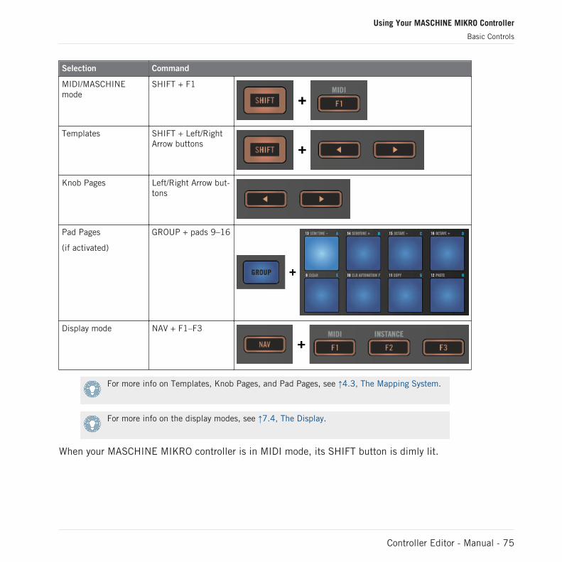
Selection Command
MIDI/MASCHINEmode
SHIFT + F1
Templates SHIFT + Left/RightArrow buttons
Knob Pages Left/Right Arrow but-tons
Pad Pages
(if activated)
GROUP + pads 9–16
Display mode NAV + F1–F3
For more info on Templates, Knob Pages, and Pad Pages, see ↑4.3, The Mapping System.
For more info on the display modes, see ↑7.4, The Display.
When your MASCHINE MIKRO controller is in MIDI mode, its SHIFT button is dimly lit.
Using Your MASCHINE MIKRO Controller
Basic Controls
Controller Editor - Manual - 75
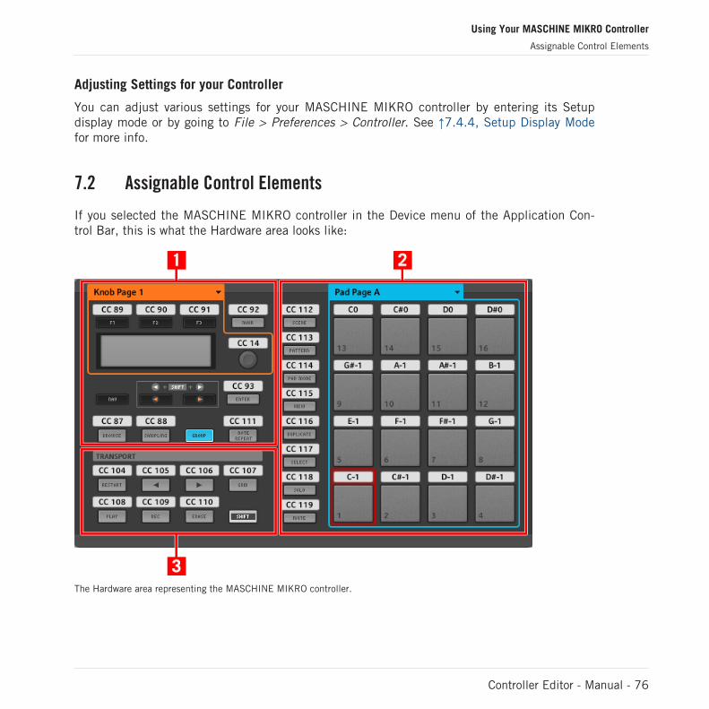
Adjusting Settings for your Controller
You can adjust various settings for your MASCHINE MIKRO controller by entering its Setupdisplay mode or by going to File > Preferences > Controller. See ↑7.4.4, Setup Display Modefor more info.
7.2 Assignable Control Elements
If you selected the MASCHINE MIKRO controller in the Device menu of the Application Con-trol Bar, this is what the Hardware area looks like:
The Hardware area representing the MASCHINE MIKRO controller.
Using Your MASCHINE MIKRO Controller
Assignable Control Elements
Controller Editor - Manual - 76

In this Hardware area, you will notice the Knob Page menu and its associated Knob Page area(orange frame), the Pad Page menu and its associated Pad Page area (blue frame), and the redSelection Frame on the currently selected control element (pad 1 in the picture above).
The MASCHINE MIKRO controller holds the following areas:
The names that you see on many control elements only refer to their original function in theMASCHINE software. We use these names here only to describe the interface!
(1) CONTROL area: In the top left part, twelve buttons and the Control encoder are arrangedaround the display. From these control elements, eight buttons are freely assignable (F1, F2,F3, MAIN, ENTER, BROWSE, SAMPLING, and NOTE REPEAT) as well as the Control encoder.The remaining four buttons (NAV, Left/Right Arrow, and GROUP) have special functions (seeprevious section).
The CONTROL area also holds the Knob Page area, indicated by an orange frame and headedby the Knob Page menu. The Knob Page area includes the F1, F2, and F3 buttons along withthe Control encoder.
The control elements in the Knob Page area can also have other functions according to thedisplay mode that is currently active. This is also the case for the ENTER button. See ↑7.4,The Display for more on this.
If the Pad Page feature is deactivated, the GROUP button becomes freely assignable aswell.
(2) PADS area: The PADS area shows a column of eight freely assignable buttons (namelySCENE, PATTERN, PAD MODE, VIEW, DUPLICATE, SELECT, SOLO, and MUTE) as well as asquare of sixteen freely assignable pads. If you activated the Enable Pad Pages button in thePages page of the Inspector, a Pad Page area (indicated by the blue frame) groups the padstogether and is headed by the Pad Page menu.
(3) TRANSPORT area: The TRANSPORT area contains eight buttons. All of them are freely as-signable except the last one, SHIFT, which has a special function (see previous section).
To Sum Up…
All control elements on your MASCHINE MIKRO controller are freely assignable to MIDI events(with the limitations due to the type of control element), with the following exceptions:
Using Your MASCHINE MIKRO Controller
Assignable Control Elements
Controller Editor - Manual - 77

▪ The NAV, Left/Right Arrow and SHIFT buttons have a predefined function (see ↑7.1, Ba-sic Controls).
▪ The GROUP button is not assignable if you use the Pad Page feature — it is used for se-lecting Pad Pages (see ↑7.1, Basic Controls). If you deactivate the Pad Pages, the GROUPbutton is freely assignable like any other button.
You can also split the controls of your controller between MIDI mode and MASCHINE modein order to control a MASCHINE plug-in instance while sending MIDI messages to the hostwith the transport controls! See ↑17.5.1, Templates Page for more info.
Assignment Parameters
The following table summarizes where to find all assignment details for each type of controlelement on your controller:
Type of Control Element Assignment Parameters
Buttons ↑17.6.2, Assignments for Buttons and the Like
Pads – Hit action ↑17.6.3, Assignments for the Pads – Hit Action
Pads – Press action ↑17.6.5, Assignments for the Pads – Press Action
Control encoder – Push action ↑17.6.2, Assignments for Buttons and the Like
Control encoder – Turn action ↑17.6.6, Assignments for Digital Encoders and the Like
7.3 Visual Feedback on your Controller
The fast bidirectional communication between your MASCHINE MIKRO controller and theHardware Service on the software side allows status indications on your controller to be madein real time.
Your MASCHINE MIKRO controller provides you visual feedback in various ways:
▪ All buttons and pads are equipped with LEDs that inform you about the assignment stateof the control element at any time.
▪ The display shows you additional info about the assignments.
Using Your MASCHINE MIKRO Controller
Visual Feedback on your Controller
Controller Editor - Manual - 78
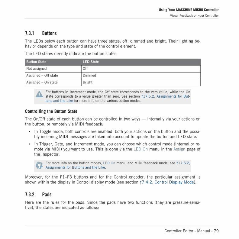
7.3.1 Buttons
The LEDs below each button can have three states: off, dimmed and bright. Their lighting be-havior depends on the type and state of the control element.
The LED states directly indicate the button states:
Button State LED State
Not assigned Off
Assigned – Off state Dimmed
Assigned – On state Bright
For buttons in Increment mode, the Off state corresponds to the zero value, while the Onstate corresponds to a value greater than zero. See section ↑17.6.2, Assignments for But-tons and the Like for more info on the various button modes.
Controlling the Button State
The On/Off state of each button can be controlled in two ways — internally via your actions onthe button, or remotely via MIDI feedback:
▪ In Toggle mode, both controls are enabled: both your actions on the button and the possi-bly incoming MIDI messages are taken into account to update the button and LED state.
▪ In Trigger, Gate, and Increment mode, you can choose which control mode (internal or re-mote via MIDI) you want to use. This is done via the LED On menu in the Assign page ofthe Inspector.
For more info on the button modes, LED On menu, and MIDI feedback mode, see ↑17.6.2,Assignments for Buttons and the Like.
Moreover, for the F1–F3 buttons and for the Control encoder, the particular assignment isshown within the display in Control display mode (see section ↑7.4.2, Control Display Mode).
7.3.2 Pads
Here are the rules for the pads. Since the pads have two functions (they are pressure-sensi-tive), the states are indicated as follows:
Using Your MASCHINE MIKRO Controller
Visual Feedback on your Controller
Controller Editor - Manual - 79
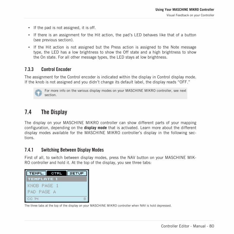
▪ If the pad is not assigned, it is off.
▪ If there is an assignment for the Hit action, the pad’s LED behaves like that of a button(see previous section).
▪ If the Hit action is not assigned but the Press action is assigned to the Note messagetype, the LED has a low brightness to show the Off state and a high brightness to showthe On state. For all other message types, the LED stays at low brightness.
7.3.3 Control Encoder
The assignment for the Control encoder is indicated within the display in Control display mode.If the knob is not assigned and you didn’t change its default label, the display reads “OFF.”
For more info on the various display modes on your MASCHINE MIKRO controller, see nextsection.
7.4 The Display
The display on your MASCHINE MIKRO controller can show different parts of your mappingconfiguration, depending on the display mode that is activated. Learn more about the differentdisplay modes available for the MASCHINE MIKRO controller’s display in the following sec-tions.
7.4.1 Switching Between Display Modes
First of all, to switch between display modes, press the NAV button on your MASCHINE MIK-RO controller and hold it. At the top of the display, you see three tabs:
The three tabs at the top of the display on your MASCHINE MIKRO controller when NAV is hold depressed.
Using Your MASCHINE MIKRO Controller
Visual Feedback on your Controller
Controller Editor - Manual - 80

These tabs allow you to select the desired display mode from the three modes available: Tem-plate, Control, and Setup:
► To switch to any of the display modes, hold the NAV button and press the desired F1–F3button above the display.
At any time, you can press the NAV button again and switch to another display mode.
7.4.2 Control Display Mode
The Control display mode is probably the one you will use the most.
► To switch to the Control display mode, press NAV + F2.
In this mode, the display shows the assignments for the currently loaded Knob Page, with itsthree button assignments on the top row for the F1–F3 buttons, and its Control encoder as-signment on the bottom row:
The Control display mode mirrors the loaded Knob Page.
In this mode, the F1–F3 buttons and the Control encoder trigger their assigned MIDI messag-es.
Each field mirrors the Label Field as defined in the Inspector’s Assign page for the correspond-ing control element: the name you defined there appears here — if you haven’t defined anyname yet for that control element, its label is simply its assigned MIDI message.
In the middle of the display, you can see the Template, Knob Page and (possibly) Pad Pagethat are currently active. You can switch these at any time using the usual shortcuts (see ↑7.1,Basic Controls).
Using Your MASCHINE MIKRO Controller
The Display
Controller Editor - Manual - 81

7.4.3 Template Display Mode
The Template display mode allows you to switch between Templates.
► To switch to the Template display mode, press NAV + F1.
The Template display mode gives you a greater control over Template switching.
In this mode, you see the list of your Templates as defined in the Inspector’s Templates page.The active Template is highlighted.
1. Turn the Control encoder to scroll through the list and find the Template you wish to loadnext.The selected Template is indicated by a dotted frame.
2. When you have it, press the Control encoder to load the selected Template.
Instead of the Control encoder, you can also use the Left/Right Arrow buttons to select an-other Template, then the ENTER button to load it.
This functionality is already available in many ways: in the Controller Editor, you can use theTemplate Select menu (in the Application Control Bar) or the Template list (in the Inspector’sTemplates page), and on the MASCHINE MIKRO controller you have the shortcut NAV + Left/Right Arrow at your disposal. The Template display mode, though, allows you a greater controlover the Template selection from your controller:
▪ Unlike the Template list in the Controller Editor interface, you don’t have to open theController Editor to switch to another Template.
▪ Unlike using the shortcut NAV + Left/Right Arrow on your controller, you can quietlychoose the next Template to be loaded, even if it’s not the one right after/before the Tem-plate currently loaded. You can check its name to remember its assignments, and you canscroll the entire list to find the Template you want.
Using Your MASCHINE MIKRO Controller
The Display
Controller Editor - Manual - 82

7.4.4 Setup Display Mode
The Setup display mode allows you to adjust relevant parameters and provides informationabout your MASCHINE MIKRO controller.
The Setup display mode provides access to parameters for your MASCHINE MIKRO controller.
The settings appear on the bottom row of the display:
1. Press the Left/Right Arrow buttons repeatedly to scroll through the available settings.2. Turn the Control encoder to change the value for a particular setting.The settings are the same as in File > Preferences > Controller (when the MASCHINE MIKROcontroller is selected in the Controller menu at the top, of course). These are:
▪ Brightness: Adjusts the brightness of the display.
▪ Contrast: Adjusts the contrast of the display.
▪ Pad Sensitivity: Changes the sensitivity of the pads.
The middle part of the display provides you with some important information about your MA-SCHINE MIKRO controller and the Hardware Service:
▪ In the upper part, you find the firmware version of your MASCHINE MIKRO controlleralong with its serial number.
▪ Below, you see the version number of the NI Hardware Service.
Using Your MASCHINE MIKRO Controller
The Display
Controller Editor - Manual - 83

8 Using Your MASCHINE MIKRO MK2 Controller
In this chapter, we will focus on what’s happening on your MASCHINE MIKRO MK2 controller.By reading this, you will learn:
▪ How to use the basic controls on your controller for navigating through the MIDI mappingsystem.
▪ The list of all assignable control elements on your controller.
▪ How the various luminous elements give you some important information about theirstate.
▪ How to use the powerful display of your MASCHINE MIKRO MK2 controller in MIDImode.
To enjoy full functionality of your NI controller as a MIDI remote control, especially con-cerning some control elements’ state and LED behavior, you need to tell your NI controllerwhat is the current state of the parameter in the MIDI target. You can do this by setting upMIDI feedback channels coming from your MIDI target back to your NI controller. This way,your controller will always stay up-to-date with the current parameter values in your targetsoftware/hardware. For more info on how to configure these MIDI feedback channels,please refer to your target software/hardware’s documentation.
8.1 Basic Controls
This section shows you the commands available on your MASCHINE MIKRO MK2 controller forbasic tasks: switching between MIDI mode and MASCHINE mode, and selecting sets (Tem-plates) and subsets (Knob Pages, Pad Pages) of MIDI assignments.
All these actions can of course be done via the Controller Editor user interface — see chap-ter ↑3, Quick Start for example. Nevertheless, using your NI controller instead can be veryhandy in a live situation!
Using Your MASCHINE MIKRO MK2 Controller
Basic Controls
Controller Editor - Manual - 84

Selection Command
MIDI/MASCHINEmode
SHIFT + F1
Templates SHIFT + Left/RightArrow buttons
Knob Pages Left/Right Arrow but-tons
Pad Pages
(if activated)
GROUP + pads 9–16
Display mode NAV + F1–F3
For more info on Templates, Knob Pages, and Pad Pages, see ↑4.3, The Mapping System.
For more info on the display modes, see ↑8.4, The Display.
When your MASCHINE MIKRO MK2 controller is in MIDI mode, its SHIFT button is dimly lit.
Using Your MASCHINE MIKRO MK2 Controller
Basic Controls
Controller Editor - Manual - 85

Adjusting Settings for your Controller
You can adjust various settings for your MASCHINE MIKRO MK2 controller by entering its Set-up display mode or by going to File > Preferences > Controller. See ↑8.4.4, Setup DisplayMode for more info.
8.2 Assignable Control Elements
If you selected the MASCHINE MIKRO MK2 controller in the Device menu of the ApplicationControl Bar, this is what the Hardware area looks like:
The Hardware area representing the MASCHINE MIKRO MK2 controller.
Using Your MASCHINE MIKRO MK2 Controller
Assignable Control Elements
Controller Editor - Manual - 86

In this Hardware area, you will notice the Knob Page menu and its associated Knob Page area(orange frame), the Pad Page menu and its associated Pad Page area (blue frame), and the redSelection Frame on the currently selected control element (pad 11 in the picture above).
The MASCHINE MIKRO MK2 controller holds the following areas:
The names that you see on many control elements only refer to their original function in theMASCHINE software. We use these names here only to describe the interface!
(1) CONTROL area: In the top left part, twelve buttons and the Control encoder are arrangedaround the display. From these control elements, eight buttons are freely assignable (F1, F2,F3, CONTROL, MAIN, BROWSE, SAMPLING, and NOTE REPEAT) as well as the Control en-coder. The remaining four buttons (NAV, Left/Right Arrow, and GROUP) have special functions(see previous section).
The CONTROL area also holds the Knob Page area, indicated by an orange frame and headedby the Knob Page menu. The Knob Page area includes the F1, F2, and F3 buttons along withthe Control encoder.
The control elements in the Knob Page area can also have other functions according to thedisplay mode that is currently active. See ↑8.4, The Display for more on this.
If the Pad Page feature is deactivated, the GROUP button becomes freely assignable aswell.
(2) PADS area: The PADS area shows a column of eight freely assignable buttons (namelySCENE, PATTERN, PAD MODE, VIEW, DUPLICATE, SELECT, SOLO, and MUTE) as well as asquare of sixteen freely assignable pads. If you activated the Enable Pad Pages button in thePages page of the Inspector, a Pad Page area (indicated by the blue frame) groups the padstogether and is headed by the Pad Page menu.
(3) TRANSPORT area: The TRANSPORT area contains eight buttons. All of them are freely as-signable except the last one, SHIFT, which has a special function (see previous section).
To Sum Up…
All control elements on your MASCHINE MIKRO MK2 controller are freely assignable to MIDIevents (with the limitations due to the type of control element), with the following exceptions:
▪ The NAV, Left/Right Arrow and SHIFT buttons have a predefined function (see ↑7.1, Ba-sic Controls).
Using Your MASCHINE MIKRO MK2 Controller
Assignable Control Elements
Controller Editor - Manual - 87

▪ The GROUP button is not assignable if you use the Pad Page feature — it is used for se-lecting Pad Pages (see ↑8.1, Basic Controls). If you deactivate the Pad Pages, the GROUPbutton is freely assignable like any other button.
You can also split the controls of your controller between MIDI mode and MASCHINE modein order to control a MASCHINE plug-in instance while sending MIDI messages to the hostwith the transport controls! See ↑17.5.1, Templates Page for more info.
Assignment Parameters
The following table summarizes where to find all assignment details for each type of controlelement on your controller:
Type of Control Element Assignment Parameters
Buttons ↑17.6.2, Assignments for Buttons and the Like
Pads – Hit action ↑17.6.3, Assignments for the Pads – Hit Action
Pads – Press action ↑17.6.5, Assignments for the Pads – Press Action
Control encoder – Push action ↑17.6.2, Assignments for Buttons and the Like
Control encoder – Turn action ↑17.6.6, Assignments for Digital Encoders and the Like
8.3 Visual Feedback on your Controller
The fast bidirectional communication between your MASCHINE MIKRO MK2 controller andthe Hardware Service on the software side allows status indications on your controller to bemade in real time.
Your MASCHINE MIKRO MK2 controller provides you visual feedback in various ways:
▪ All buttons and pads are equipped with LEDs that inform you about their assignment atany time. Furthermore, the 16 pads and the GROUP button provide RGB LEDs.
▪ The display shows you additional info about the assignments.
8.3.1 Buttons
Basically, each button on your controller can have three states:
Using Your MASCHINE MIKRO MK2 Controller
Visual Feedback on your Controller
Controller Editor - Manual - 88
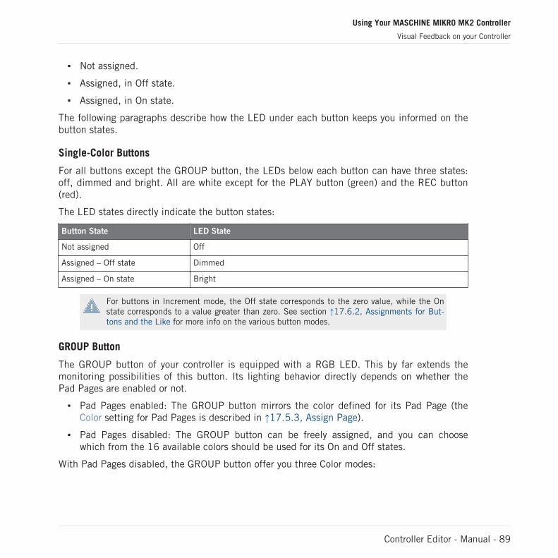
▪ Not assigned.
▪ Assigned, in Off state.
▪ Assigned, in On state.
The following paragraphs describe how the LED under each button keeps you informed on thebutton states.
Single-Color Buttons
For all buttons except the GROUP button, the LEDs below each button can have three states:off, dimmed and bright. All are white except for the PLAY button (green) and the REC button(red).
The LED states directly indicate the button states:
Button State LED State
Not assigned Off
Assigned – Off state Dimmed
Assigned – On state Bright
For buttons in Increment mode, the Off state corresponds to the zero value, while the Onstate corresponds to a value greater than zero. See section ↑17.6.2, Assignments for But-tons and the Like for more info on the various button modes.
GROUP Button
The GROUP button of your controller is equipped with a RGB LED. This by far extends themonitoring possibilities of this button. Its lighting behavior directly depends on whether thePad Pages are enabled or not.
▪ Pad Pages enabled: The GROUP button mirrors the color defined for its Pad Page (theColor setting for Pad Pages is described in ↑17.5.3, Assign Page).
▪ Pad Pages disabled: The GROUP button can be freely assigned, and you can choosewhich from the 16 available colors should be used for its On and Off states.
With Pad Pages disabled, the GROUP button offer you three Color modes:
Using Your MASCHINE MIKRO MK2 Controller
Visual Feedback on your Controller
Controller Editor - Manual - 89

▪ Single mode: You can choose a color that will be used bright and dimmed for the On andOff states, respectively. In this mode, the button’s lighting behaves like the single-colorbuttons described above.
▪ Dual mode: You can choose a color for the On state and another color for the Off state.Both colors will be used at full brightness.
▪ HSB mode: This mode is only available when the button’s state is controlled via MIDIfeedback (see below). In HSB mode, you can precisely define from within your MIDI tar-get which color the button will use.
Controlling the Button State
The On/Off state of each button can be controlled in two ways — internally via your actions onthe button, or remotely via MIDI feedback:
▪ In Toggle mode, both controls are enabled: both your actions on the button and the possi-bly incoming MIDI messages are taken into account to update the button and LED state.
▪ In Trigger, Gate, and Increment mode, you can choose which control mode (internal or re-mote via MIDI) you want to use. This is done via the LED On menu in the Assign page ofthe Inspector.
For more info on the button modes, LED On menu, and MIDI feedback mode, see ↑17.6.2,Assignments for Buttons and the Like.
Moreover, for the F1–F3 buttons, the particular assignment is shown within the display in Con-trol display mode (see section ↑8.4.2, Control Display Mode).
8.3.2 Multicolor Pads
The sixteen pads of your controller are equipped with RGB LEDs. Their lighting behavior isclose to that of the GROUP button — but since the pads have two functions (Hit and Press),their states are indicated as follows:
▪ If the pad is not assigned, it is off.
▪ If there is an assignment for the Hit action, the pad’s LED behaves like that of a multicol-or Group button (see previous section).
Using Your MASCHINE MIKRO MK2 Controller
Visual Feedback on your Controller
Controller Editor - Manual - 90

▪ If the Hit action is not assigned but the Press action is assigned to the Note messagetype, the LED has a low brightness to show the Off state and a high brightness to showthe On state. For all other message types, the LED stays at low brightness.
8.3.3 Control Encoder
The assignment for the Control encoder is indicated within the display in Control display mode.If the knob is not assigned and you didn’t change its default label, the display reads “OFF.”
For more info on the various display modes on your MASCHINE MIKRO MK2 controller, seenext section.
8.4 The Display
The display on your MASCHINE MIKRO MK2 controller can show different parts of your map-ping configuration, depending on the display mode that is activated. Learn more about the dif-ferent display modes available for the MASCHINE MIKRO MK2 controller’s display in the fol-lowing sections.
8.4.1 Switching Between Display Modes
First of all, to switch between display modes, press the NAV button on your MASCHINE MIK-RO MK2 controller and hold it. At the top of the display, you see three tabs:
The three tabs at the top of the display on your MASCHINE MIKRO MK2 controller when NAV is hold depressed.
These tabs allow you to select the desired display mode from the three modes available: Tem-plate, Control, and Setup:
Using Your MASCHINE MIKRO MK2 Controller
Visual Feedback on your Controller
Controller Editor - Manual - 91

► To switch to any of the display modes, hold the NAV button and press the desired F1–F3button above the display.
At any time, you can press the NAV button again and switch to another display mode.
8.4.2 Control Display Mode
The Control display mode is probably the one you will use the most.
► To switch to the Control display mode, press NAV + F2.
In this mode, the display shows the assignments for the currently loaded Knob Page, with itsthree button assignments on the top row for the F1–F3 buttons, and its Control encoder as-signment on the bottom row:
The Control display mode mirrors the loaded Knob Page.
In this mode, the F1–F3 buttons and the Control encoder trigger their assigned MIDI messag-es.
Each field mirrors the Label Field as defined in the Inspector’s Assign page for the correspond-ing control element: the name you defined there appears here — if you haven’t defined anyname yet for that control element, its label is simply its assigned MIDI message.
In the middle of the display, you can see the Template, Knob Page and (possibly) Pad Pagethat are currently active. You can switch these at any time using the usual shortcuts (see ↑7.1,Basic Controls).
8.4.3 Template Display Mode
The Template display mode allows you to switch between Templates.
► To switch to the Template display mode, press NAV + F1.
Using Your MASCHINE MIKRO MK2 Controller
The Display
Controller Editor - Manual - 92

The Template display mode gives you a greater control over Template switching.
In this mode, you see the list of your Templates as defined in the Inspector’s Templates page.The active Template is highlighted.
1. Turn the Control encoder to scroll through the list and find the Template you wish to loadnext.The selected Template is indicated by a dotted frame.
2. When you have it, press the Control encoder to load the selected Template.
Instead of turning the Control encoder, you can also use the Left/Right Arrow buttons to se-lect another Template, then press the Control encoder to load it.
This functionality is already available in many ways: in the Controller Editor, you can use theTemplate Select menu (in the Application Control Bar) or the Template list (in the Inspector’sTemplates page), and on the MASCHINE MIKRO MK2 controller you have the shortcut NAV +Left/Right Arrow at your disposal. The Template display mode, though, allows you a greatercontrol over the Template selection from your controller:
▪ Unlike the Template list in the Controller Editor interface, you don’t have to open theController Editor to switch to another Template.
▪ Unlike using the shortcut NAV + Left/Right Arrow buttons on your controller, you can qui-etly choose the next Template to be loaded, even if it’s not the one right after/before theTemplate currently loaded. You can check its name to remember its assignments, and youcan scroll the entire list to find the Template you want.
8.4.4 Setup Display Mode
The Setup display mode allows you to adjust relevant parameters and provides informationabout your MASCHINE MIKRO MK2 controller.
Using Your MASCHINE MIKRO MK2 Controller
The Display
Controller Editor - Manual - 93
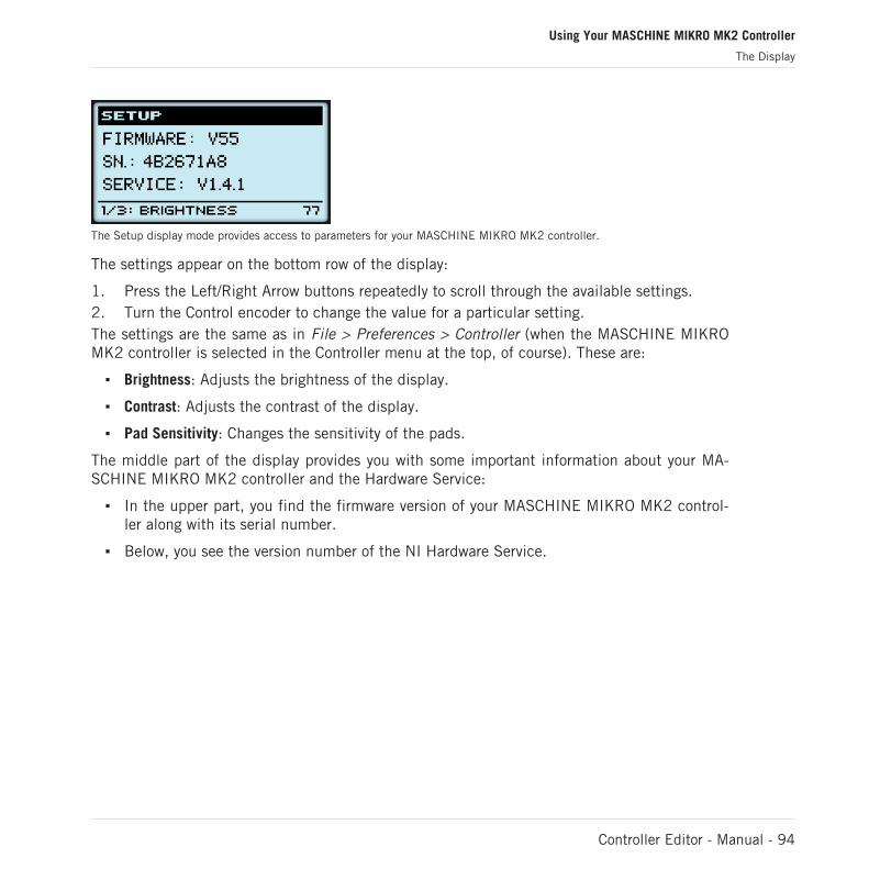
The Setup display mode provides access to parameters for your MASCHINE MIKRO MK2 controller.
The settings appear on the bottom row of the display:
1. Press the Left/Right Arrow buttons repeatedly to scroll through the available settings.2. Turn the Control encoder to change the value for a particular setting.The settings are the same as in File > Preferences > Controller (when the MASCHINE MIKROMK2 controller is selected in the Controller menu at the top, of course). These are:
▪ Brightness: Adjusts the brightness of the display.
▪ Contrast: Adjusts the contrast of the display.
▪ Pad Sensitivity: Changes the sensitivity of the pads.
The middle part of the display provides you with some important information about your MA-SCHINE MIKRO MK2 controller and the Hardware Service:
▪ In the upper part, you find the firmware version of your MASCHINE MIKRO MK2 control-ler along with its serial number.
▪ Below, you see the version number of the NI Hardware Service.
Using Your MASCHINE MIKRO MK2 Controller
The Display
Controller Editor - Manual - 94

9 Using Your KORE Controller
In this chapter, we will focus on what’s happening on your KORE Controller. By reading this,you will learn:
▪ How to use the basic controls on your controller for navigating through the MIDI mappingsystem.
▪ The list of all assignable control elements on your controller.
▪ How the various luminous elements give you some important information about theirstate.
▪ How to use the Display of your KORE Controller in MIDI mode.
To enjoy full functionality of your NI controller as a MIDI remote control, especially con-cerning some control elements’ state and LED behavior, you need to tell your NI controllerwhat is the current state of the parameter in the MIDI target. You can do this by setting upMIDI feedback channels coming from your MIDI target back to your NI controller. This way,your controller will always stay up-to-date with the current parameter values in your targetsoftware/hardware. For more info on how to configure these MIDI feedback channels,please refer to your target software/hardware’s documentation.
9.1 Basic Controls
This section shows you the commands available on your KORE Controller for basic tasks:switching between MIDI mode and KORE mode, and selecting sets (Templates) and subsets(Knob Pages) of MIDI assignments.
All these actions can of course be done via the Controller Editor user interface — see chap-ter ↑3, Quick Start for example. Nevertheless, using your NI controller instead can be veryhandy in a live situation!
Using Your KORE Controller
Basic Controls
Controller Editor - Manual - 95
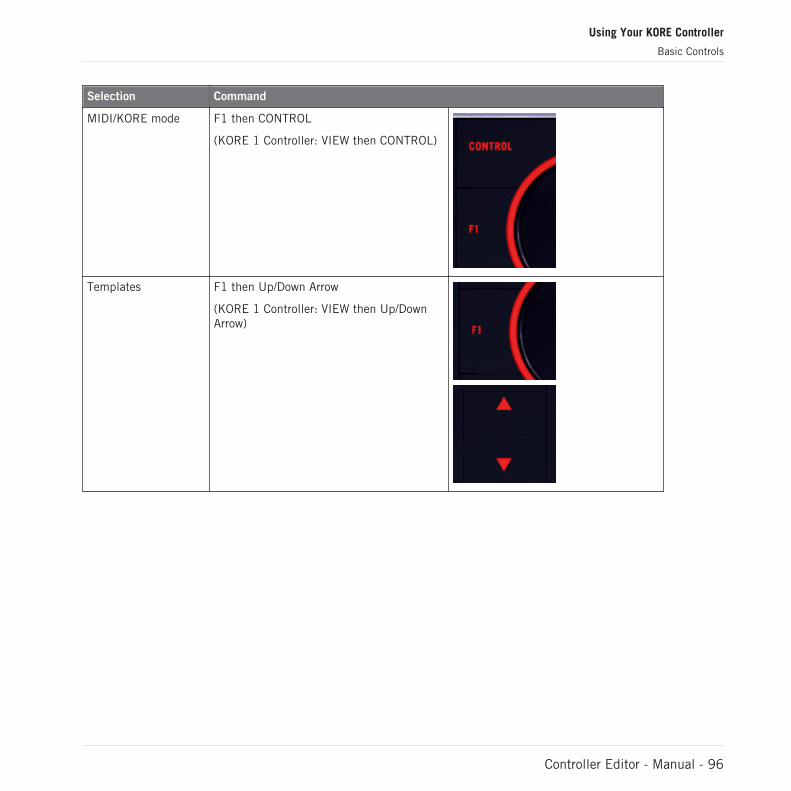
Selection Command
MIDI/KORE mode F1 then CONTROL
(KORE 1 Controller: VIEW then CONTROL)
Templates F1 then Up/Down Arrow
(KORE 1 Controller: VIEW then Up/DownArrow)
Using Your KORE Controller
Basic Controls
Controller Editor - Manual - 96
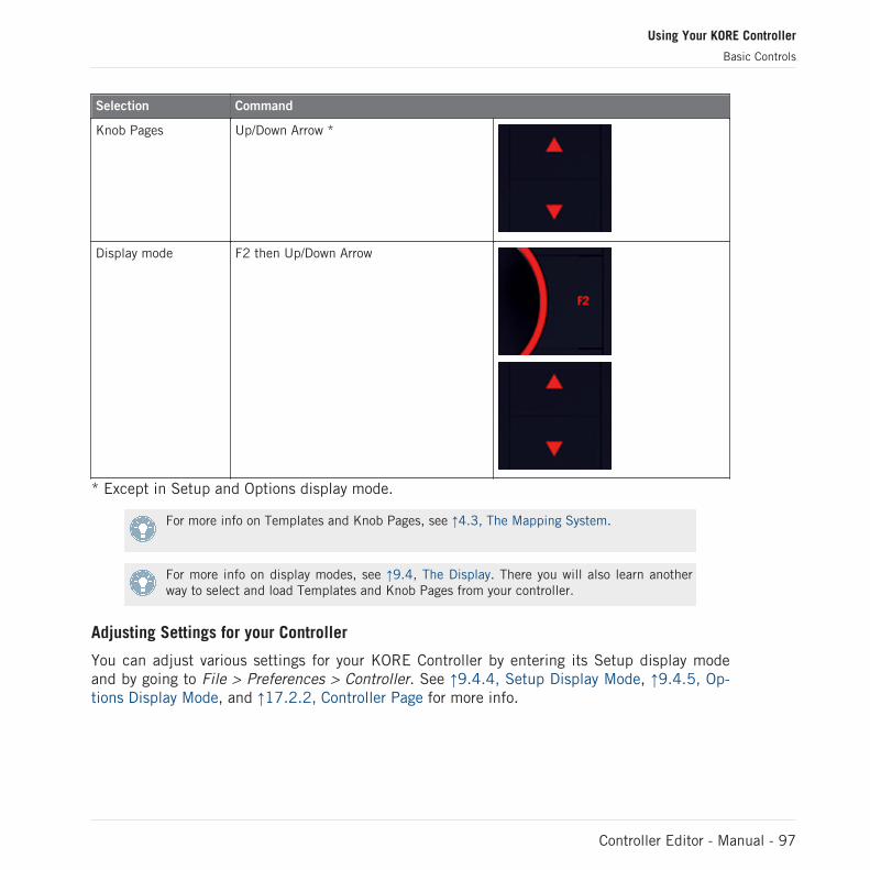
Selection Command
Knob Pages Up/Down Arrow *
Display mode F2 then Up/Down Arrow
* Except in Setup and Options display mode.
For more info on Templates and Knob Pages, see ↑4.3, The Mapping System.
For more info on display modes, see ↑9.4, The Display. There you will also learn anotherway to select and load Templates and Knob Pages from your controller.
Adjusting Settings for your Controller
You can adjust various settings for your KORE Controller by entering its Setup display modeand by going to File > Preferences > Controller. See ↑9.4.4, Setup Display Mode, ↑9.4.5, Op-tions Display Mode, and ↑17.2.2, Controller Page for more info.
Using Your KORE Controller
Basic Controls
Controller Editor - Manual - 97

9.2 Assignable Control Elements
9.2.1 KORE 2 Controller
If you selected the KORE 2 Controller in the Device menu of the Application Control Bar, thisis what the Hardware area looks like:
The Hardware area representing the KORE 2 Controller.
In this Hardware area, you will notice the Knob Page menu and its associated Knob Page area(orange frame), and the red Selection Frame on the currently selected control element (Con-troller Knob #1 in the picture above).
The KORE 2 Controller holds the following areas:
The names that you see on many control elements only refer to their original function in theKORE 2 software.
Using Your KORE Controller
Assignable Control Elements
Controller Editor - Manual - 98

(1) Knob Page area: The Knob Page area holds a set of eight buttons and eight knobs, repre-senting the eight Controller Buttons and eight Controller Knobs of your KORE Controller. Thesesixteen control elements are freely assignable. The Knob Page area is headed by the KnobPage menu.
(2) Pedal area: The Pedal area holds four freely assignable control elements corresponding tothe two Pedal Inputs and the two Footswitch Ports.
Before you can use any external pedal, you need to calibrate it. This is done via the Con-troller page of the Preferences window. See ↑17.2.2, Controller Page for more info.
(3) Left/Right and Up/Down Arrow buttons: In the central part of the KORE 2 Controller view, thefour Arrow buttons have specific functions (see previous section and ↑9.4, The Display).
(4) Scrollwheel and surrounding buttons: In the right part, the Scrollwheel and the surroundingfour buttons (namely CONTROL, SOUND, ESC and ENTER on your KORE 2 Controller) definefive freely assignable control elements. The two other buttons, F1 and F2, have predefinedfunctions and therefore cannot be assigned to any MIDI command (see previous section and↑9.4, The Display).
(5) Transport area: The Transport area contains four buttons (Stop, Start, Record and Pre-Lis-ten). All of them are freely assignable.
To Sum Up…
All control elements of the KORE 2 Controller are freely assignable to any MIDI event (with thelimitations due to the type of control element), with the following exceptions:
▪ The four Arrow buttons.
▪ The F1 and F2 buttons.
Assignment Parameters
The following table summarizes where to find all assignment details for each type of controlelement on your controller:
Type of Control Element Assignment Parameters
Buttons ↑17.6.2, Assignments for Buttons and the Like
Controller Knobs – Touch action ↑17.6.2, Assignments for Buttons and the Like
Using Your KORE Controller
Assignable Control Elements
Controller Editor - Manual - 99
Type of Control Element Assignment Parameters
Controller Knobs – Turn action ↑17.6.7, Assignments for Analog Encoders and the Like
Scroll Wheel ↑17.6.6, Assignments for Digital Encoders and the Like
Footswitch inputs ↑17.6.2, Assignments for Buttons and the Like
Pedal inputs ↑17.6.4, Assignments for Knobs and the Like
9.2.2 KORE 1 Controller
The KORE 1 Controller is very similar to the KORE 2 Controller. Regarding MIDI remote con-trol, these are the differences:
▪ In the Pedal area, there is only one pedal input instead of two.
▪ The buttons around the Scrollwheel have slightly different layout and names: If the fourfreely assignable buttons are exactly the same as on the KORE 2 Controller, the two func-tion buttons are called VIEW (instead of F1) and MENU (instead of F2) and laid out verti-cally instead of horizontally around the Scrollwheel. But since these buttons are not as-signable, it won’t change much for us. If you own a KORE 1 Controller, simply think“VIEW” when we say “F1” and “MENU” when we say “F2.”
9.3 Visual Feedback on your Controller
The fast bidirectional communication between your KORE Controller and the Hardware Serviceon the software side allows status indications on your controller to be made in real time.
Your KORE Controller provides you visual feedback in various ways:
▪ All assignable control elements (apart from the pedal/footswitch inputs) are equipped withLEDs that inform you about the assignment state of the control element at any time.
▪ The Display shows you additional info about the assignments.
9.3.1 Buttons
The LEDs below each button can have three states: off, dimmed and bright. Their lighting be-havior depends on the state of the control element.
Using Your KORE Controller
Assignable Control Elements
Controller Editor - Manual - 100

The following table indicates you the possible states for the LEDs:
Button State LED State
Not assigned Off
Assigned – Off state Dimmed
Assigned – On state Bright
For buttons in Increment mode, the Off state corresponds to the zero value, while the Onstate corresponds to a value greater than zero.
Controlling the Button State
The state of each button can be controlled in two ways — internally via your actions on thebutton, or remotely via MIDI feedback:
▪ In Toggle mode, both controls are enabled: both your actions on the button and the possi-bly incoming MIDI messages are taken into account to update the button state.
▪ In Trigger, Gate, and Increment mode, you can choose which control mode you want touse via the LED On menu located in the Assign page of the Inspector.
For more info on the button modes, LED On menu, and MIDI feedback mode, see ↑17.6.2,Assignments for Buttons and the Like.
Furthermore, the assignments for the Controller Buttons (i.e. the buttons arranged in two linesabove and below the Controller Knobs) are indicated within the Display of your KORE Control-ler in Control display mode (see section ↑9.4.2, Control Display Mode). If one of these buttonsis not assigned, the Display reads “Off.”
9.3.2 Controller Knobs
The LED ring around each Controller Knob informs you about the state of the Turn action ofthis knob:
▪ If the Controller Knob is not assigned, its LED ring is off.
▪ If the Controller Knob is assigned, the LED ring’s brightness reflects the MIDI value, rela-tively to the range of values defined for this Controller Knob.
Using Your KORE Controller
Visual Feedback on your Controller
Controller Editor - Manual - 101

The assignments for the Controller Knobs along with their current value are indicated withinthe Display of your KORE Controller in Control display mode (see section ↑9.4.2, Control Dis-play Mode). If a Controller Knob is not assigned, the Display reads “Off.”
9.3.3 Scrollwheel
Regarding its LED ring’s behavior, the Scrollwheel of the KORE Controller behaves like theTurn action on the Controller Knobs (see previous section).
It is not possible to see the assignment for the Scrollwheel on your hardware: you need to lookat the Controller Editor window.
9.3.4 Pedal Inputs and Footswitch Ports
Obviously, Pedal inputs and Footswitch ports don’t have any LED!
There is no way to see their assignment on your hardware: to do this, you have to check theController Editor window.
9.4 The Display
On your KORE Controller, the Display can show useful information, thus allowing you to adjustdifferent parameters. In this way you do not have to open the Controller Editor on your comput-er while working with your KORE Controller.
The Display can show different parts of your mapping configuration, depending on the displaymode that is activated. The five available display modes are: Control, Knob Pages, Templates,Setup and Options. In each display mode, the Display Header (at the top of the Display) alwaysreminds you of the current display mode.
The following sections describe each of these display modes.
9.4.1 Switching between Display Modes
The selection of a particular display mode is mainly done via the F2 button.
► Press the F2 button to show the Overview Screen on your Display.
Using Your KORE Controller
Visual Feedback on your Controller
Controller Editor - Manual - 102

The Overview Screen on the Display of your KORE Controller
This screen allows you to select the desired display mode. The available display modes are pre-sented in a matrix with two rows of four cells each, similar to the Sound Variations in theKORE Software. The four display modes available here are:
▪ Knob Page (labeled “PAGE”)
▪ Control (labeled “CTL”)
▪ Setup (labeled “SET”)
▪ Options (labeled “OPTN”)
To switch to any of them, you can:
► Navigate with the four Arrow buttons (Up, Down, Left and Right) to put the target frameon the desired cell and press the ENTER button to confirm your choice.
or
► Press the corresponding Controller Button on your KORE Controller for a direct access tothat display mode. You will notice that the Controller Buttons activating a particular dis-play mode are judiciously lit, whereas those not doing anything stay dark.
From this Overview Screen, you can also switch back to the previously selected display mode:
► Press the ESC button on your KORE Controller to switch back to the previously selecteddisplay mode.
At any time, you can press the F2 button again to get to the Overview Screen and switch toanother display mode.
Exception: the Templates Display Mode
To activate the Templates display mode:
Using Your KORE Controller
The Display
Controller Editor - Manual - 103

► Press the F1 button (see section ↑9.4.6, Templates Display Mode below for more info onthis mode).
9.4.2 Control Display Mode
The Control display mode is probably the one you will use the most.
► To activate the Control display mode, press F2 (to show the Overview Screen) then theButton 2 or the CONTROL button.
You can also press F2 and use the Arrow buttons to select the cell “CTL” on the OverviewScreen, and subsequently press the ENTER button.
In this mode, the Display shows the currently loaded Knob Page. By default, it displays theassignments for the eight Controller Buttons on the top and bottom rows, and the eight assign-ments for the Controller Knobs on the two middle rows:
The Control display mode mirrors the currently loaded Knob Page. This display mode allows you to see which MIDI messageis currently assigned to each control element in the loaded Knob Page. In this mode, the 8 Controller Buttons and 8 Control-ler Knobs of your KORE Controller trigger their assigned MIDI messages.
The Display Header first shows “CTL” (to remind you that you are in the Control display mode),followed by the name of the currently loaded Knob Page.
The Control display mode has three views, similar to those of the Control display mode whenusing the KORE Controller with the KORE 2 Software.
Using Your KORE Controller
The Display
Controller Editor - Manual - 104
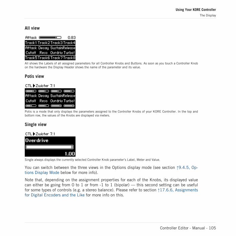
All view
All shows the Labels of all assigned parameters for all Controller Knobs and Buttons. As soon as you touch a Controller Knobon the hardware the Display Header shows the name of the parameter and its value.
Potis view
Potis is a mode that only displays the parameters assigned to the Controller Knobs of your KORE Controller. In the top andbottom row, the values of the Knobs are displayed via meters.
Single view
Single always displays the currently selected Controller Knob parameter’s Label, Meter and Value.
You can switch between the three views in the Options display mode (see section ↑9.4.5, Op-tions Display Mode below for more info).
Note that, depending on the assignment properties for each of the Knobs, its displayed valuecan either be going from 0 to 1 or from -1 to 1 (bipolar) — this second setting can be usefulfor some types of controls (e.g. a stereo balance). Please refer to section ↑17.6.6, Assignmentsfor Digital Encoders and the Like for more info on this.
Using Your KORE Controller
The Display
Controller Editor - Manual - 105

9.4.3 Knob Pages Display Mode
The Knob Pages display mode allows you to switch between Knob Pages.
► To activate the Knob Pages display mode, press F2 (to show the Overview Screen) thenthe Button 1.
You can also press F2 and use the Arrow buttons to select the “PAGE” cell on the OverviewScreen, and subsequently press the ENTER button.
On the Display, you see the list of your Knob Pages, as defined in the Pages list of the Inspector’s Pages page.
1. Use the Scrollwheel to scroll through the list and find the Knob Page you wish to loadnext.
2. Press the ENTER button on your KORE Controller to load the selected Knob Page.
The current assignments for the 8 Controller Buttons and 8 Controller Knobs stay activewhen the Knob Pages display mode is activated.
Actually, this functionality is already available in many ways: in the Controller Editor, you canuse the Knob Page menu (in the Hardware area) or the Pages list (in the Inspector’s Pagespage), and on the KORE Controller in Control display mode you have the Page buttons at yourdisposal (the Up and Down Arrow buttons). But the Knob Pages display mode provides exten-sive control over the Knob Page selection from within the KORE Controller:
▪ Unlike the Knob Page menu and Pages list, you don’t have to open the Controller Editorto switch to another Knob Page.
▪ Unlike the Page buttons on your KORE Controller, you can quietly choose the next KnobPage to be loaded, even if it’s not the one right after/before the currently loaded KnobPage. You can check its name to remember its assignments, and you can scroll the entirelist to find the page you want before to load any.
Using Your KORE Controller
The Display
Controller Editor - Manual - 106

9.4.4 Setup Display Mode
The Setup display mode allows you to tweak settings for your KORE Controller.
► To activate the Setup display mode, press F2 (to show the Overview Screen) then theButton 7.
You can also press F2 and use the Arrow buttons to select the “SET” cell on the OverviewScreen, and subsequently press the ENTER button.
The settings are the same as in File > Preferences > Controller (when the KORE Controller is selected in the Controller menuat the top, of course). You will find these three parameters:
▪ Contrast: Changes the contrast of the Display.
▪ Backlight: Changes the background lighting of the Display.
▪ Touch Sens: Adjusts the touch sensitivity of the eight Controller Knobs on your Controller.
You can use the four Arrow buttons to select a particular parameter and modify its value.
The current assignments for the 8 Controller Buttons and 8 Controller Knobs stay activewhen the Setup display mode is activated.
9.4.5 Options Display Mode
► To activate the Options display mode, press F2 (to show the Overview Screen), then But-ton 8.
You can also press F2 and use the Arrow buttons to select the “OPTN” cell on the OverviewScreen, and subsequently press the ENTER button.
Using Your KORE Controller
The Display
Controller Editor - Manual - 107
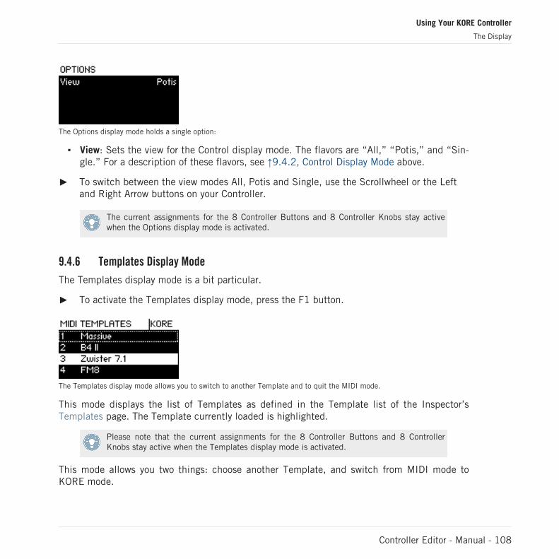
The Options display mode holds a single option:
▪ View: Sets the view for the Control display mode. The flavors are “All,” “Potis,” and “Sin-gle.” For a description of these flavors, see ↑9.4.2, Control Display Mode above.
► To switch between the view modes All, Potis and Single, use the Scrollwheel or the Leftand Right Arrow buttons on your Controller.
The current assignments for the 8 Controller Buttons and 8 Controller Knobs stay activewhen the Options display mode is activated.
9.4.6 Templates Display Mode
The Templates display mode is a bit particular.
► To activate the Templates display mode, press the F1 button.
The Templates display mode allows you to switch to another Template and to quit the MIDI mode.
This mode displays the list of Templates as defined in the Template list of the Inspector’sTemplates page. The Template currently loaded is highlighted.
Please note that the current assignments for the 8 Controller Buttons and 8 ControllerKnobs stay active when the Templates display mode is activated.
This mode allows you two things: choose another Template, and switch from MIDI mode toKORE mode.
Using Your KORE Controller
The Display
Controller Editor - Manual - 108
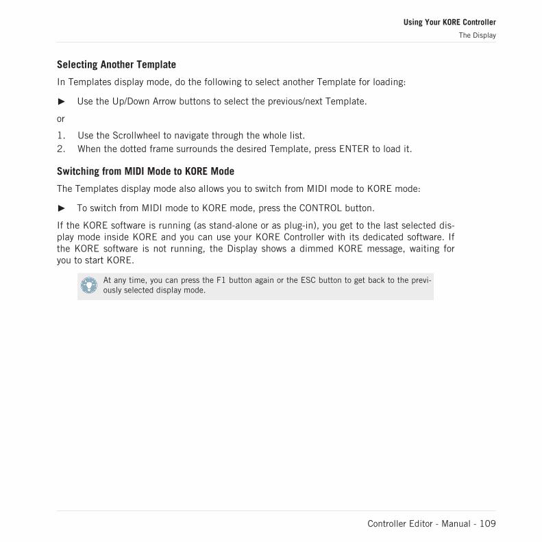
Selecting Another Template
In Templates display mode, do the following to select another Template for loading:
► Use the Up/Down Arrow buttons to select the previous/next Template.
or
1. Use the Scrollwheel to navigate through the whole list.2. When the dotted frame surrounds the desired Template, press ENTER to load it.
Switching from MIDI Mode to KORE Mode
The Templates display mode also allows you to switch from MIDI mode to KORE mode:
► To switch from MIDI mode to KORE mode, press the CONTROL button.
If the KORE software is running (as stand-alone or as plug-in), you get to the last selected dis-play mode inside KORE and you can use your KORE Controller with its dedicated software. Ifthe KORE software is not running, the Display shows a dimmed KORE message, waiting foryou to start KORE.
At any time, you can press the F1 button again or the ESC button to get back to the previ-ously selected display mode.
Using Your KORE Controller
The Display
Controller Editor - Manual - 109

10 Using Your TRAKTOR KONTROL X1
In this chapter, we will focus on what’s happening on your TRAKTOR KONTROL X1. By read-ing this, you will learn:
▪ How to use the basic controls on your controller for navigating through the MIDI mappingsystem.
▪ The list of all assignable control elements on your controller.
▪ How the various luminous elements give you some important information about theirstate.
▪ How to configure more than one X1 unit for use as MIDI remote controls.
10.1 Basic Controls
This section shows you the commands available on your TRAKTOR KONTROL X1 for basictasks: switching between MIDI mode and TRAKTOR mode, and selecting subsets (Knob Pages)of MIDI assignments.
All these actions can of course be done via the Controller Editor user interface — see chap-ter ↑3, Quick Start for example. Nevertheless, using your NI controller instead can be veryhandy in a live situation!
Selection Command
MIDI/TRAKTOR mode SHIFT + HOTCUE
Knob Pages SHIFT
Using Your TRAKTOR KONTROL X1
Basic Controls
Controller Editor - Manual - 110
For more info on the Knob Pages, see ↑4.3, The Mapping System.
You cannot switch between Templates from the TRAKTOR KONTROL X1. To do this, youhave to use the Controller Editor interface (see ↑3.2, Loading MIDI Assignments).
When your X1 is in MIDI mode, the HOTCUE button is lit in green.
Switching Between Knob Pages: Gate vs. Toggle
The SHIFT button can have two operating modes:
▪ Gate mode: The Knob Page is activated for the time the button is hold depressed.
▪ Toggle mode: The Knob Page is activated until the next time you press the button again.
You can choose the desired mode for the SHIFT button in the Controller Editor. To do this:
1. Check that the TRAKTOR KONTROL X1 is selected in the Device menu.2. On the Pages page of the Inspector, click the Shift Mode menu and select the desired
mode Gate or Toggle.
Adjusting Settings for your Controller
You can adjust various settings for your TRAKTOR KONTROL X1 in File > Preferences > Con-troller. See ↑17.2.2, Controller Page for more info.
10.2 Assignable Control Elements
If you selected the TRAKTOR KONTROL X1 in the Device menu of the Application Control Bar,this is what the Hardware area looks like:
Using Your TRAKTOR KONTROL X1
Assignable Control Elements
Controller Editor - Manual - 111
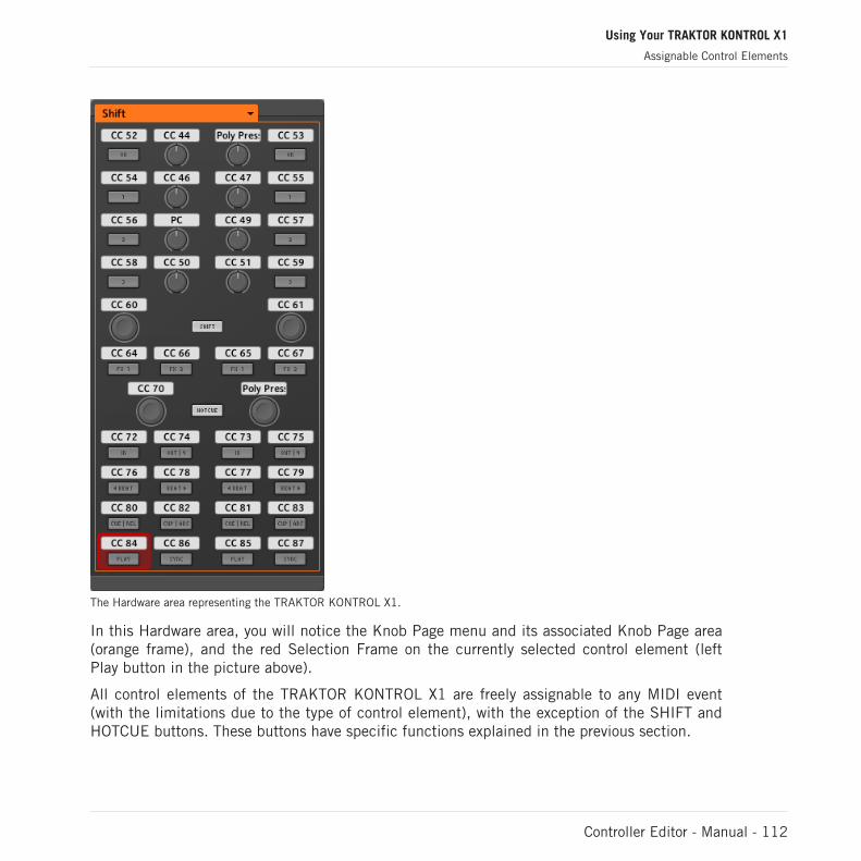
The Hardware area representing the TRAKTOR KONTROL X1.
In this Hardware area, you will notice the Knob Page menu and its associated Knob Page area(orange frame), and the red Selection Frame on the currently selected control element (leftPlay button in the picture above).
All control elements of the TRAKTOR KONTROL X1 are freely assignable to any MIDI event(with the limitations due to the type of control element), with the exception of the SHIFT andHOTCUE buttons. These buttons have specific functions explained in the previous section.
Using Your TRAKTOR KONTROL X1
Assignable Control Elements
Controller Editor - Manual - 112
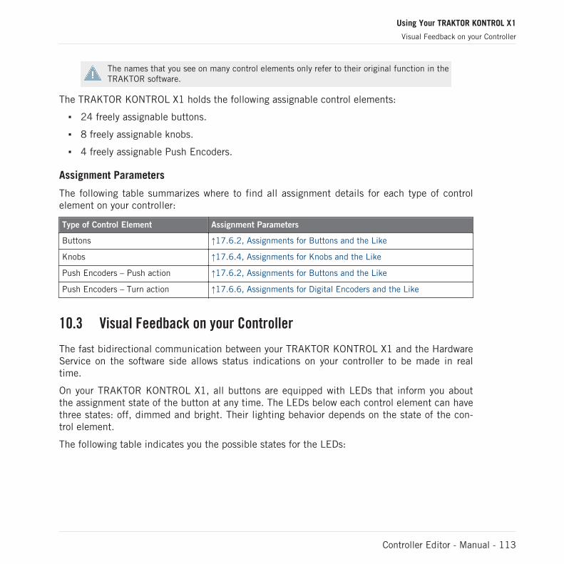
The names that you see on many control elements only refer to their original function in theTRAKTOR software.
The TRAKTOR KONTROL X1 holds the following assignable control elements:
▪ 24 freely assignable buttons.
▪ 8 freely assignable knobs.
▪ 4 freely assignable Push Encoders.
Assignment Parameters
The following table summarizes where to find all assignment details for each type of controlelement on your controller:
Type of Control Element Assignment Parameters
Buttons ↑17.6.2, Assignments for Buttons and the Like
Knobs ↑17.6.4, Assignments for Knobs and the Like
Push Encoders – Push action ↑17.6.2, Assignments for Buttons and the Like
Push Encoders – Turn action ↑17.6.6, Assignments for Digital Encoders and the Like
10.3 Visual Feedback on your Controller
The fast bidirectional communication between your TRAKTOR KONTROL X1 and the HardwareService on the software side allows status indications on your controller to be made in realtime.
On your TRAKTOR KONTROL X1, all buttons are equipped with LEDs that inform you aboutthe assignment state of the button at any time. The LEDs below each control element can havethree states: off, dimmed and bright. Their lighting behavior depends on the state of the con-trol element.
The following table indicates you the possible states for the LEDs:
Using Your TRAKTOR KONTROL X1
Visual Feedback on your Controller
Controller Editor - Manual - 113

Button State LED State
Not assigned Off
Assigned – Off state Dimmed
Assigned – On state Bright
For buttons in Increment mode, the Off state corresponds to the zero value, while the Onstate corresponds to a value greater than zero.
Controlling the Button State
The state of each button can be controlled in two ways — internally via your actions on thebutton, or remotely via MIDI feedback:
▪ In Toggle mode, both controls are enabled: both your actions on the button and the possi-bly incoming MIDI messages are taken into account to update the button state.
▪ In Trigger, Gate, and Increment mode, you can choose which control mode you want touse via the LED On menu located in the Assign page of the Inspector.
For more info on the button modes, LED On menu, and MIDI feedback mode, see ↑17.6.2,Assignments for Buttons and the Like.
Adjusting the LED Brightness
You can adjust the LED brightness for both On and Off button states in File > Preferences >Controller > Traktor Kontrol X1 - x > LEDs (see ↑17.2, The Preferences Window for more infoon the Preferences window).
10.4 Using Two or More TRAKTOR KONTROL X1 Units
You can use up to four TRAKTOR KONTROL X1 units simultaneously. This allows you to fur-ther extend the number of parameters you can control in your target(s). For more info on howto set up more than one TRAKTOR KONTROL X1 for use with the same computer, please referto chapter ↑16, Using Two or More Units of the Same Type.
Using Your TRAKTOR KONTROL X1
Using Two or More TRAKTOR KONTROL X1 Units
Controller Editor - Manual - 114

11 Using Your TRAKTOR KONTROL F1
In this chapter, we will focus on what’s happening on your TRAKTOR KONTROL F1. By read-ing this, you will learn:
▪ How to use the basic controls on your controller for navigating through the MIDI mappingsystem.
▪ The list of all assignable control elements on your controller.
▪ How the various luminous elements give you some important information about theirstate.
▪ How to configure more than one F1 unit for use as MIDI remote controls.
11.1 Basic Controls
This section shows you the commands available on your TRAKTOR KONTROL F1 for basictasks: switching between MIDI mode and TRAKTOR mode, and selecting subsets (Knob Pages)of MIDI assignments.
All these actions can of course be done via the Controller Editor user interface — see chap-ter ↑3, Quick Start for example. Nevertheless, using your NI controller instead can be veryhandy in a live situation!
Selection Command
MIDI/TRAKTOR mode SHIFT + BROWSE
Knob Pages SHIFT
Using Your TRAKTOR KONTROL F1
Basic Controls
Controller Editor - Manual - 115
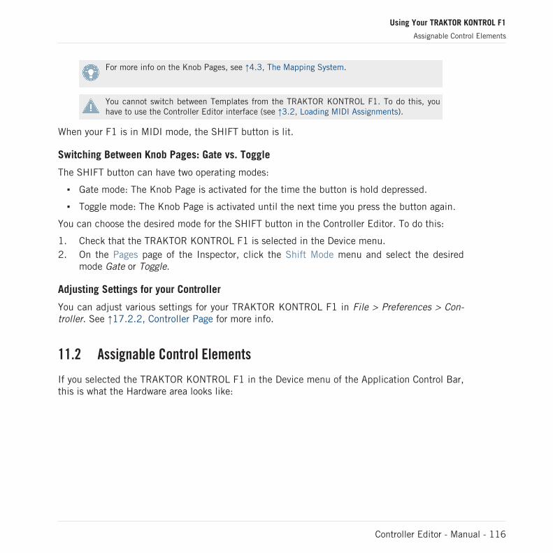
For more info on the Knob Pages, see ↑4.3, The Mapping System.
You cannot switch between Templates from the TRAKTOR KONTROL F1. To do this, youhave to use the Controller Editor interface (see ↑3.2, Loading MIDI Assignments).
When your F1 is in MIDI mode, the SHIFT button is lit.
Switching Between Knob Pages: Gate vs. Toggle
The SHIFT button can have two operating modes:
▪ Gate mode: The Knob Page is activated for the time the button is hold depressed.
▪ Toggle mode: The Knob Page is activated until the next time you press the button again.
You can choose the desired mode for the SHIFT button in the Controller Editor. To do this:
1. Check that the TRAKTOR KONTROL F1 is selected in the Device menu.2. On the Pages page of the Inspector, click the Shift Mode menu and select the desired
mode Gate or Toggle.
Adjusting Settings for your Controller
You can adjust various settings for your TRAKTOR KONTROL F1 in File > Preferences > Con-troller. See ↑17.2.2, Controller Page for more info.
11.2 Assignable Control Elements
If you selected the TRAKTOR KONTROL F1 in the Device menu of the Application Control Bar,this is what the Hardware area looks like:
Using Your TRAKTOR KONTROL F1
Assignable Control Elements
Controller Editor - Manual - 116

The Hardware area representing the TRAKTOR KONTROL F1.
In this Hardware area, you will notice the Knob Page menu and its associated Knob Page area(orange frame), and the red Selection Frame on the currently selected control element (firstFILTER knob in the picture above).
All control elements of the TRAKTOR KONTROL F1 are freely assignable to any MIDI event(with the limitations due to the type of control element), with the exception of the SHIFT but-ton. This button has a specific function explained in the previous section.
Using Your TRAKTOR KONTROL F1
Assignable Control Elements
Controller Editor - Manual - 117
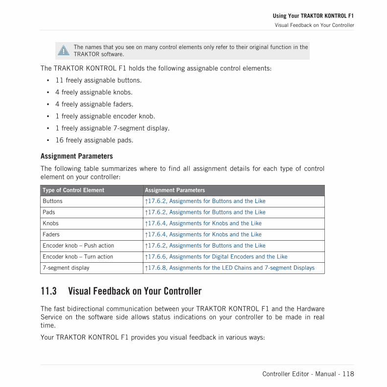
The names that you see on many control elements only refer to their original function in theTRAKTOR software.
The TRAKTOR KONTROL F1 holds the following assignable control elements:
▪ 11 freely assignable buttons.
▪ 4 freely assignable knobs.
▪ 4 freely assignable faders.
▪ 1 freely assignable encoder knob.
▪ 1 freely assignable 7-segment display.
▪ 16 freely assignable pads.
Assignment Parameters
The following table summarizes where to find all assignment details for each type of controlelement on your controller:
Type of Control Element Assignment Parameters
Buttons ↑17.6.2, Assignments for Buttons and the Like
Pads ↑17.6.2, Assignments for Buttons and the Like
Knobs ↑17.6.4, Assignments for Knobs and the Like
Faders ↑17.6.4, Assignments for Knobs and the Like
Encoder knob – Push action ↑17.6.2, Assignments for Buttons and the Like
Encoder knob – Turn action ↑17.6.6, Assignments for Digital Encoders and the Like
7-segment display ↑17.6.8, Assignments for the LED Chains and 7-segment Displays
11.3 Visual Feedback on Your Controller
The fast bidirectional communication between your TRAKTOR KONTROL F1 and the HardwareService on the software side allows status indications on your controller to be made in realtime.
Your TRAKTOR KONTROL F1 provides you visual feedback in various ways:
Using Your TRAKTOR KONTROL F1
Visual Feedback on Your Controller
Controller Editor - Manual - 118

▪ All buttons and pads are equipped with LEDs that inform you about the assignment stateof the control element at any time.
▪ The 7-segment display shows you additional info about the assignment of your choice.
11.3.1 Buttons and Pads
The LEDs below each button can have three states: off, dimmed and bright. Their lighting be-havior depends on the state of the control element.
The following table indicates you the possible states for the LEDs:
Button State LED State
Not assigned Off
Assigned – Off state Dimmed
Assigned – On state Bright
For buttons in Increment mode, the Off state corresponds to the zero value, while the Onstate corresponds to a value greater than zero.
Multicolor Pads
As for the pads, they are equipped with RGB LEDs. This by far extends the monitoring possibil-ities of these control elements. Indeed, you can choose which from the 16 available colors youwant to use for the On and Off states — and this, for each pad individually!
The pads offer you three Color modes:
▪ Single mode: You can choose a color that will be used bright and dimmed for the On andOff states, respectively. In this mode, the pad’s lighting behaves like the buttons (see ta-ble above).
▪ Dual mode: You can choose a color for the On state and another color for the Off state.Both colors will be used at full brightness.
▪ HSB mode: This mode is only available when the pad’s state is controlled via MIDI feed-back (see below). In HSB mode, you can precisely define from within your MIDI targetwhich color the pad will use.
Using Your TRAKTOR KONTROL F1
Visual Feedback on Your Controller
Controller Editor - Manual - 119

Controlling the State of the Control Elements
The state of each button/pad can be controlled in two ways — internally via your actions on it,or remotely via MIDI feedback:
▪ In Toggle mode, both controls are enabled: both your actions on the control element andthe possibly incoming MIDI messages are taken into account to update the button state.
▪ In Trigger, Gate, and Increment mode, you can choose which control mode you want touse via the LED On menu located in the Assign page of the Inspector.
For more info on the modes, LED On menu, and MIDI feedback mode, see ↑17.6.2, As-signments for Buttons and the Like.
Adjusting the LED Brightness
You can adjust the LED brightness for both On and Off states in File > Preferences > Controller> Traktor Kontrol F1 - x > LEDs (see ↑17.2, The Preferences Window for more info on the Pref-erences window).
11.3.2 7-segment Display
The 7-segment display next to the encoder knob can display any MIDI Note’ velocity or anyMIDI CC value. The displayed value depends on the display’s assignment settings as defined inthe Assign page of the Inspector. See ↑17.6.8, Assignments for the LED Chains and 7-seg-ment Displays for more info on the possible assignments.
Since the 7-segment display holds two digits and possible values range from 0 to 127, valuesare displayed as follows:
▪ Values within 0–99 are displayed as 0–99.
▪ Values within 100–127 are displayed as 0–27 with an additional dot (•) at the top leftcorner of the display (meaning “+100”).
The 7-segment display reading 82 (left) and 126 (right).
Using Your TRAKTOR KONTROL F1
Visual Feedback on Your Controller
Controller Editor - Manual - 120

11.4 Using Two or More TRAKTOR KONTROL F1 Units
You can use up to four TRAKTOR KONTROL F1 units simultaneously. This allows you to fur-ther extend the number of parameters you can control in your target(s). For more info on howto set up more than one TRAKTOR KONTROL F1 for use with the same computer, please referto chapter ↑16, Using Two or More Units of the Same Type.
Using Your TRAKTOR KONTROL F1
Using Two or More TRAKTOR KONTROL F1 Units
Controller Editor - Manual - 121
12 Using Your TRAKTOR KONTROL S4
In this chapter, we will focus on what’s happening on your TRAKTOR KONTROL S4. By read-ing this, you will learn:
▪ How to use the basic controls on your controller for navigating through the MIDI mappingsystem.
▪ The list of all assignable control elements on your controller.
▪ How the various luminous elements give you some important information about theirstate.
To enjoy full functionality of your NI controller as a MIDI remote control, especially con-cerning some control elements’ state and LED behavior, you need to tell your NI controllerwhat is the current state of the parameter in the MIDI target. You can do this by setting upMIDI feedback channels coming from your MIDI target back to your NI controller. This way,your controller will always stay up-to-date with the current parameter values in your targetsoftware/hardware. For more info on how to configure these MIDI feedback channels,please refer to your target software/hardware’s documentation.
12.1 Basic Controls
This section shows you the commands available on your TRAKTOR KONTROL S4 for basictasks: switching between MIDI mode and TRAKTOR mode, selecting the desired Deck on eachside, and selecting subsets (Knob Pages) of MIDI assignments.
All these actions can of course be done via the Controller Editor user interface — see chap-ter ↑3, Quick Start for example. Nevertheless, using your NI controller instead can be veryhandy in a live situation!
Using Your TRAKTOR KONTROL S4
Basic Controls
Controller Editor - Manual - 122
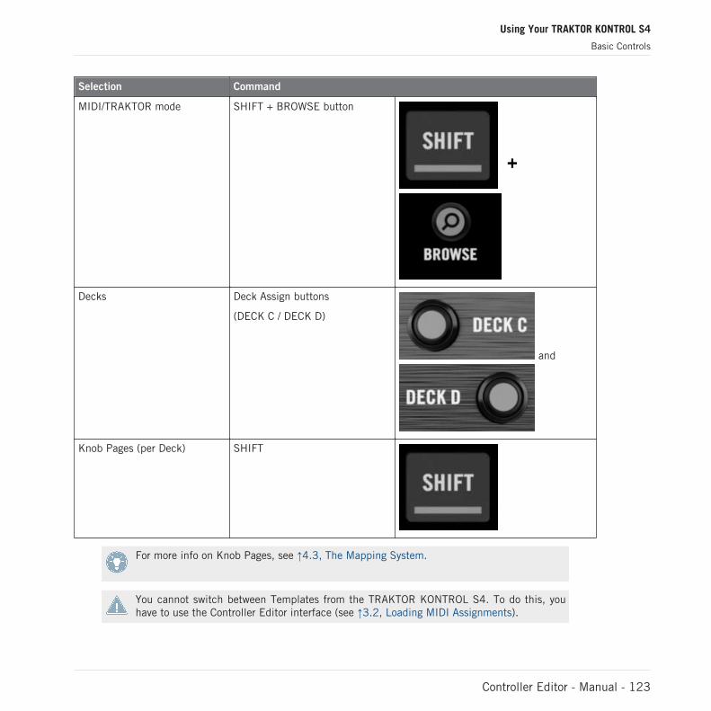
Selection Command
MIDI/TRAKTOR mode SHIFT + BROWSE button
Decks Deck Assign buttons
(DECK C / DECK D)
and
Knob Pages (per Deck) SHIFT
For more info on Knob Pages, see ↑4.3, The Mapping System.
You cannot switch between Templates from the TRAKTOR KONTROL S4. To do this, youhave to use the Controller Editor interface (see ↑3.2, Loading MIDI Assignments).
Using Your TRAKTOR KONTROL S4
Basic Controls
Controller Editor - Manual - 123

When your S4 is in MIDI mode, both Loop Size Displays on your S4 read “ON” (meaning thatMIDI mode is on).
Switching Between Decks and Knob Pages
In MIDI mode, the S4 takes up TRAKTOR’s 4-Deck scheme. In other terms, the available KnobPages are organized per Deck, Decks A to D providing two Knob Pages each (whose defaultnames are “Basic” and “Shift”). Thus, to load any of these Knob Pages, do the following:
1. Switch to the desired Deck using the Deck Assign buttons (DECK C on the left Deck,DECK D on the right Deck).When you switch to the lower Deck (C on the left, D on the right), the DECK C (or DECKD) indicator lights up in the Deck Display while the DECK A (or DECK B) indicator turnsoff — this to remind you which Deck is currently active.
2. Switch to the desired Knob Page for that Deck using the SHIFT button of that Deck.Please keep in mind that the DECK C and DECK D buttons are always in Toggle mode: Whenyou press one of them, the Deck controls switch to the alternate Deck until you press the but-ton again.
Switching Between Knob Pages: Gate vs. Toggle
The SHIFT buttons can have two operating modes:
▪ Gate mode: The Knob Page is activated for the time the button is hold depressed.
▪ Toggle mode: The Knob Page is activated until the next time you press the button again.
You can choose the desired mode for the SHIFT button in the Controller Editor. To do this:
1. Check that the TRAKTOR KONTROL S4 is selected in the Device menu.2. On the Pages page of the Inspector, click the Shift Mode menu and select the desired
mode Gate or Toggle.
Adjusting Settings for your Controller
You can adjust various settings for your TRAKTOR KONTROL S4 in File > Preferences > Con-troller. See ↑17.2.2, Controller Page for more info.
Using Your TRAKTOR KONTROL S4
Basic Controls
Controller Editor - Manual - 124

12.2 Assignable Control Elements
If you selected the TRAKTOR KONTROL S4 in the Device menu of the Application Control Bar,depending on the part of the S4 that you selected in the S4 Overview (in the top left corner),this is what the Hardware area looks like:
In this Hardware area, you will notice the Knob Page menu and its associated Knob Page area(orange frame) when the left or right Deck is displayed, and the red Selection Frame on thecurrently selected control element.
The names that you see on some control elements only refer to their original function in theTRAKTOR software.
12.2.1 Control Elements on the Left Deck
Here is the list of all assignable control elements on the Left Deck of your S4.
Using Your TRAKTOR KONTROL S4
Assignable Control Elements
Controller Editor - Manual - 125

The Left Deck on the TRAKTOR KONTROL S4.
The Left Deck of the TRAKTOR KONTROL S4 holds the following areas:
(1) Knob Page area: The Knob Page area holds all Deck controls. Apart from the Deck Assign(DECK C) and SHIFT buttons, all these control elements are freely assignable: 17 buttons, 2encoders, 1 fader, and 1 jog wheel. The Knob Page area is headed by the Knob Page menu.
(2) FX area: This area holds 5 buttons and 4 knobs, all of them freely assignable.
Using Your TRAKTOR KONTROL S4
Assignable Control Elements
Controller Editor - Manual - 126

(3) Footswitch input: The footswitch input of your S4 can also be freely assigned to any MIDIevent.
You will find all details concerning the assignment parameters for the control elements in↑17.6, MIDI Message Parameters.
12.2.2 Control Elements on the Right Deck
The Right Deck of the TRAKTOR KONTROL S4 is very similar to the Left Deck describedabove. It holds the same control elements, with the following exceptions:
▪ There is no footswitch input.
▪ There are two additional knobs (CUE MIX and MIC VOL) located on the front panel of yourS4. These knobs are freely assignable.
12.2.3 Control Elements on the Mixer
Here is the list of all assignable control elements on the Mixer of your S4.
Using Your TRAKTOR KONTROL S4
Assignable Control Elements
Controller Editor - Manual - 127
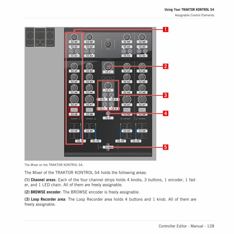
The Mixer on the TRAKTOR KONTROL S4.
The Mixer of the TRAKTOR KONTROL S4 holds the following areas:
(1) Channel areas: Each of the four channel strips holds 4 knobs, 3 buttons, 1 encoder, 1 fad-er, and 1 LED chain. All of them are freely assignable.
(2) BROWSE encoder: The BROWSE encoder is freely assignable.
(3) Loop Recorder area: The Loop Recorder area holds 4 buttons and 1 knob. All of them arefreely assignable.
Using Your TRAKTOR KONTROL S4
Assignable Control Elements
Controller Editor - Manual - 128

(4) BROWSE button: The BROWSE button is freely assignable.
(5) Crossfader: The crossfader is freely assignable as well.
On the Mixer, the Main section (with the MAIN LEVEL knob and MAIN LEVEL meters), theMaster Display (with the Alert, USB, and Preview Play indicators along with the SNAP,MASTER, and QUANT buttons), and the Deck Assignment indicators are excluded from theMIDI mapping scheme. In other terms, you cannot assign MIDI events to any of these con-trol elements.
12.2.4 Assignment Parameters
The following table summarizes where to find all assignment details for each type of controlelement on your controller:
Type of Control Element Assignment Parameters
Buttons ↑17.6.2, Assignments for Buttons and the Like
Footswitch input ↑17.6.2, Assignments for Buttons and the Like
Knobs ↑17.6.4, Assignments for Knobs and the Like
Faders and crossfader ↑17.6.4, Assignments for Knobs and the Like
Encoders – Push action ↑17.6.2, Assignments for Buttons and the Like
Encoders – Turn action ↑17.6.6, Assignments for Digital Encoders and the Like
LED chains ↑17.6.8, Assignments for the LED Chains and 7-segment Displays
12.3 Visual Feedback on your Controller
The fast bidirectional communication between your TRAKTOR KONTROL S4 and the HardwareService on the software side allows status indications on your controller to be made in realtime.
Using Your TRAKTOR KONTROL S4
Assignable Control Elements
Controller Editor - Manual - 129
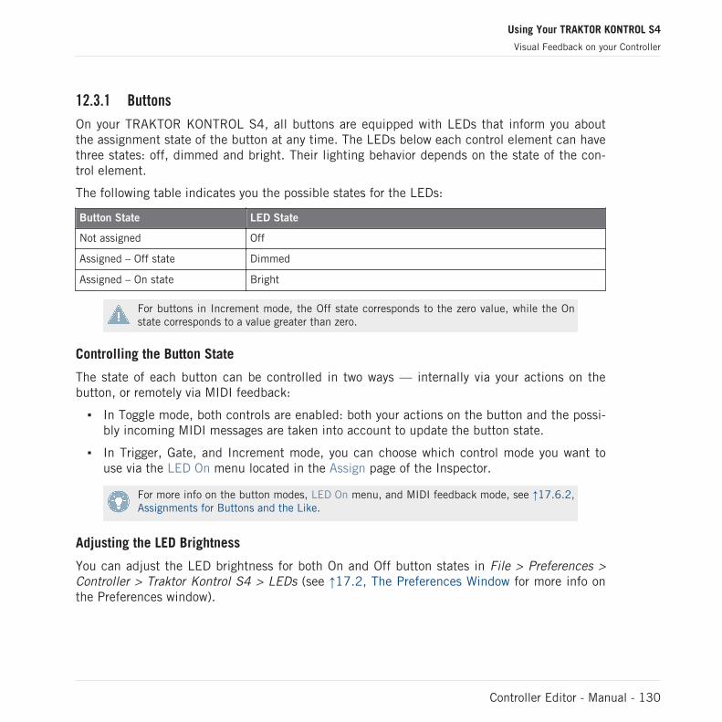
12.3.1 Buttons
On your TRAKTOR KONTROL S4, all buttons are equipped with LEDs that inform you aboutthe assignment state of the button at any time. The LEDs below each control element can havethree states: off, dimmed and bright. Their lighting behavior depends on the state of the con-trol element.
The following table indicates you the possible states for the LEDs:
Button State LED State
Not assigned Off
Assigned – Off state Dimmed
Assigned – On state Bright
For buttons in Increment mode, the Off state corresponds to the zero value, while the Onstate corresponds to a value greater than zero.
Controlling the Button State
The state of each button can be controlled in two ways — internally via your actions on thebutton, or remotely via MIDI feedback:
▪ In Toggle mode, both controls are enabled: both your actions on the button and the possi-bly incoming MIDI messages are taken into account to update the button state.
▪ In Trigger, Gate, and Increment mode, you can choose which control mode you want touse via the LED On menu located in the Assign page of the Inspector.
For more info on the button modes, LED On menu, and MIDI feedback mode, see ↑17.6.2,Assignments for Buttons and the Like.
Adjusting the LED Brightness
You can adjust the LED brightness for both On and Off button states in File > Preferences >Controller > Traktor Kontrol S4 > LEDs (see ↑17.2, The Preferences Window for more info onthe Preferences window).
Using Your TRAKTOR KONTROL S4
Visual Feedback on your Controller
Controller Editor - Manual - 130

12.3.2 LED Chains
The Mixer of the S4 proposes you four assignable LED chains that give you an additional visualfeedback on your target’s parameters. The feedback provided by each LED chain depends onits assignment settings as defined in the Assign page of the Inspector. See ↑17.6.8, Assign-ments for the LED Chains and 7-segment Displays for more info on the possible assignments.
Using Your TRAKTOR KONTROL S4
Visual Feedback on your Controller
Controller Editor - Manual - 131

13 Using Your TRAKTOR KONTROL S2
In this chapter, we will focus on what’s happening on your TRAKTOR KONTROL S2. By read-ing this, you will learn:
▪ How to use the basic controls on your controller for switching your controller to/from MIDImode.
▪ The list of all assignable control elements on your controller.
▪ How the various luminous elements give you some important information about theirstate.
To enjoy full functionality of your NI controller as a MIDI remote control, especially con-cerning some control elements’ state and LED behavior, you need to tell your NI controllerwhat is the current state of the parameter in the MIDI target. You can do this by setting upMIDI feedback channels coming from your MIDI target back to your NI controller. This way,your controller will always stay up-to-date with the current parameter values in your targetsoftware/hardware. For more info on how to configure these MIDI feedback channels,please refer to your target software/hardware’s documentation.
13.1 Basic Controls
Here is how to switch between MIDI mode and TRAKTOR mode from your TRAKTOR KON-TROL S2.
This can of course be done via the Controller Editor user interface — see chapter ↑3, QuickStart for example. Nevertheless, using your NI controller instead can be very handy in a livesituation!
Selection Command
MIDI/TRAKTOR mode SHIFT + SHIFT (on both Decks)
Using Your TRAKTOR KONTROL S2
Basic Controls
Controller Editor - Manual - 132

When your S2 is in MIDI mode, both SHIFT buttons are dimly lit (meaning that MIDI mode ison).
You cannot switch between Templates from the TRAKTOR KONTROL S2. To do this, youhave to use the Controller Editor interface (see ↑3.2, Loading MIDI Assignments).
Adjusting Settings for your Controller
You can adjust various settings for your TRAKTOR KONTROL S2 in File > Preferences > Con-troller. See ↑17.2.2, Controller Page for more info.
13.2 Assignable Control Elements
If you selected the TRAKTOR KONTROL S2 in the Device menu of the Application Control Bar,depending on the part of the S2 that you selected in the S2 Overview (in the top left corner),this is what the Hardware area looks like:
In this Hardware area, you will notice the red Selection Frame on the currently selected controlelement.
The names that you see on some control elements only refer to their original function in theTRAKTOR software.
On your TRAKTOR KONTROL S2, almost every control element is freely assignable to a MIDIevent. The few exceptions are the following:
Using Your TRAKTOR KONTROL S2
Assignable Control Elements
Controller Editor - Manual - 133
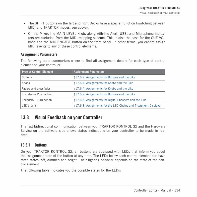
▪ The SHIFT buttons on the left and right Decks have a special function (switching betweenMIDI and TRAKTOR modes, see above).
▪ On the Mixer, the MAIN LEVEL knob, along with the Alert, USB, and Microphone indica-tors are excluded from the MIDI mapping scheme. This is also the case for the CUE VOLknob and the MIC ENGAGE button on the front panel. In other terms, you cannot assignMIDI events to any of these control elements.
Assignment Parameters
The following table summarizes where to find all assignment details for each type of controlelement on your controller:
Type of Control Element Assignment Parameters
Buttons ↑17.6.2, Assignments for Buttons and the Like
Knobs ↑17.6.4, Assignments for Knobs and the Like
Faders and crossfader ↑17.6.4, Assignments for Knobs and the Like
Encoders – Push action ↑17.6.2, Assignments for Buttons and the Like
Encoders – Turn action ↑17.6.6, Assignments for Digital Encoders and the Like
LED chains ↑17.6.8, Assignments for the LED Chains and 7-segment Displays
13.3 Visual Feedback on your Controller
The fast bidirectional communication between your TRAKTOR KONTROL S2 and the HardwareService on the software side allows status indications on your controller to be made in realtime.
13.3.1 Buttons
On your TRAKTOR KONTROL S2, all buttons are equipped with LEDs that inform you aboutthe assignment state of the button at any time. The LEDs below each control element can havethree states: off, dimmed and bright. Their lighting behavior depends on the state of the con-trol element.
The following table indicates you the possible states for the LEDs:
Using Your TRAKTOR KONTROL S2
Visual Feedback on your Controller
Controller Editor - Manual - 134
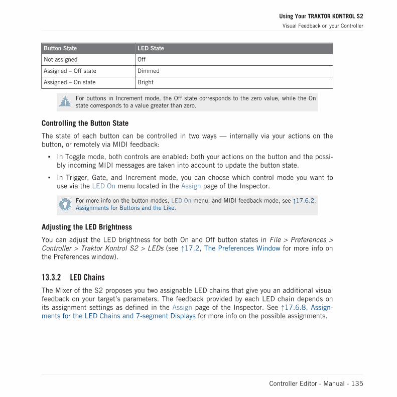
Button State LED State
Not assigned Off
Assigned – Off state Dimmed
Assigned – On state Bright
For buttons in Increment mode, the Off state corresponds to the zero value, while the Onstate corresponds to a value greater than zero.
Controlling the Button State
The state of each button can be controlled in two ways — internally via your actions on thebutton, or remotely via MIDI feedback:
▪ In Toggle mode, both controls are enabled: both your actions on the button and the possi-bly incoming MIDI messages are taken into account to update the button state.
▪ In Trigger, Gate, and Increment mode, you can choose which control mode you want touse via the LED On menu located in the Assign page of the Inspector.
For more info on the button modes, LED On menu, and MIDI feedback mode, see ↑17.6.2,Assignments for Buttons and the Like.
Adjusting the LED Brightness
You can adjust the LED brightness for both On and Off button states in File > Preferences >Controller > Traktor Kontrol S2 > LEDs (see ↑17.2, The Preferences Window for more info onthe Preferences window).
13.3.2 LED Chains
The Mixer of the S2 proposes you two assignable LED chains that give you an additional visualfeedback on your target’s parameters. The feedback provided by each LED chain depends onits assignment settings as defined in the Assign page of the Inspector. See ↑17.6.8, Assign-ments for the LED Chains and 7-segment Displays for more info on the possible assignments.
Using Your TRAKTOR KONTROL S2
Visual Feedback on your Controller
Controller Editor - Manual - 135
14 Using Your RIG KONTROL 3
In this chapter, we will focus on what’s happening on your RIG KONTROL 3. We will first listall assignable control elements on your controller, then describe how the various luminous ele-ments inform you about their state.
14.1 Basic Controls
The RIG KONTROL 3 does not hold any function-specific control elements: you are free to as-sign each and every control found on your controller.
There are no Knob Pages available for the RIG KONTROL 3.
You cannot switch between Templates from the RIG KONTROL 3. To do this, you have touse the Controller Editor interface (see ↑3.2, Loading MIDI Assignments for example).
Switching Between MIDI Mode and GUITAR RIG Mode
You cannot switch between MIDI mode and GUITAR RIG mode from the RIG KONTROL 3. Toswitch the RIG KONTROL 3 to MIDI mode:
► Simply start the Controller Editor.
Or, if the Controller Editor is already running:
► Use the Connect button in the Application Control Bar (see ↑3.1, Switching your NI Con-troller to MIDI Mode).
Inversely, if you want the RIG KONTROL 3 to control the GUITAR RIG software again (or oneof its instances), you need to re-connect it. To do this:
► Simply start GUITAR RIG.
Or, if GUITAR RIG is already running:
Using Your RIG KONTROL 3
Basic Controls
Controller Editor - Manual - 136

1. Show the Virtual Rig Kontrol in the GUITAR RIG window by activating its button in theToolbar, at the top of the Rack:
2. In the Virtual Rig Kontrol that appears at the bottom of the Rack, click the CONNECTLED in the top left corner:
14.2 Assignable Control Elements
If you selected the RIG KONTROL 3 in the Device menu of the Application Control Bar, this iswhat the Hardware area looks like:
The Hardware area representing the RIG KONTROL 3.
In this Hardware area, you will notice the red Selection Frame on the currently selected controlelement (Footswitch 8 in the picture above).
Using Your RIG KONTROL 3
Assignable Control Elements
Controller Editor - Manual - 137

All control elements of the RIG KONTROL 3 are freely assignable to any MIDI event (with thelimitations due to the type of control element).
The RIG KONTROL 3 holds the following areas:
(1) Footswitches: In the left and main part, the Footswitches are a set of eight buttons repre-senting the eight Footswitches of your RIG KONTROL 3. These eight control elements are free-ly assignable.
(2) Pedal area: On the top, the Pedal area holds two freely assignable control elements corre-sponding to the two Pedal Inputs.
(3) Expression Pedal: In the right part, the Expression Pedal holds two freely assignable controlelements: the Expression Pedal itself and the Expression Pedal Switch, located under the ped-al on your RIG KONTROL 3.
Before you can use any pedal (Expression Pedal or external pedal), you need to calibrate it.This is done via the Controller page of the Preferences window. See ↑17.2.2, ControllerPage for more info.
Assignment Parameters
The following table summarizes where to find all assignment details for each type of controlelement on your controller:
Type of Control Element Assignment Parameters
Footswitches ↑17.6.2, Assignments for Buttons and the Like
Expression Pedal Switch ↑17.6.2, Assignments for Buttons and the Like
Expression Pedal ↑17.6.4, Assignments for Knobs and the Like
Pedal inputs ↑17.6.4, Assignments for Knobs and the Like
14.3 Visual Feedback on your Controller
Most control elements on your RIG KONTROL 3 are equipped with LEDs that inform you aboutthe assignment status of the control elements at any time. The fast bidirectional communica-tion between your RIG KONTROL 3 and the Hardware Service on the software side allows sta-tus indications on your controller to be made in real time.
Using Your RIG KONTROL 3
Visual Feedback on your Controller
Controller Editor - Manual - 138

The LEDs on each control element can have two states: on or off. Their lighting behavior de-pends on the type and state of the control element.
14.3.1 Footswitches
The following table indicates you the possible states for the LEDs of the eight Footswitches onyour RIG KONTROL 3:
Footswitch State LED State
Not assigned Off
Assigned – Off state Off
Assigned – On state On
For Footswitches in Increment mode, the Off state corresponds to the zero value, while theOn state corresponds to a value greater than zero.
Controlling the Footswitch State
The state of each Footswitch can be controlled in two ways — internally via your actions on theFootswitch, or remotely via MIDI feedback:
▪ In Toggle mode, both controls are enabled: both your actions on the Footswitch and thepossibly incoming MIDI messages are taken into account to update the Footswitch state.
▪ In Trigger, Gate, and Increment mode, you can choose which control mode you want touse via the LED On menu located in the Assign page of the Inspector.
For more info on the various button modes, LED On menu, and MIDI feedback mode, see↑17.6.2, Assignments for Buttons and the Like.
14.3.2 Expression Pedal
The assignment for the Expression Pedal itself is not shown by any LED: just look at the pedaland you will know its state!
The assignment for the Expression Pedal Switch is shown by the Pedal Switch LED (labelledPEDAL, in the upper row of indicators on your RIG KONTROL 3): Its behavior is the same asfor Footswitches (see above).
Using Your RIG KONTROL 3
Visual Feedback on your Controller
Controller Editor - Manual - 139
14.3.3 Pedal Inputs
Obviously, the Pedal inputs don’t have any LED! There is no way to see their assignment onyour hardware: to do this, you have to check the Controller Editor window.
14.4 The Display
The LED Display of your RIG KONTROL 3 simply informs you about the current mode of yourController:
▪ In GUITAR RIG mode (i.e. if your Controller is connected to an instance of its dedicatedsoftware), the LED Display shows you the number of the preset currently loaded.
▪ In MIDI mode (i.e. if your Controller is connected to the Controller Editor / NI HardwareService), the LED Display shows the letters “con” (for “Controller Editor”).
Using Your RIG KONTROL 3
Visual Feedback on your Controller
Controller Editor - Manual - 140
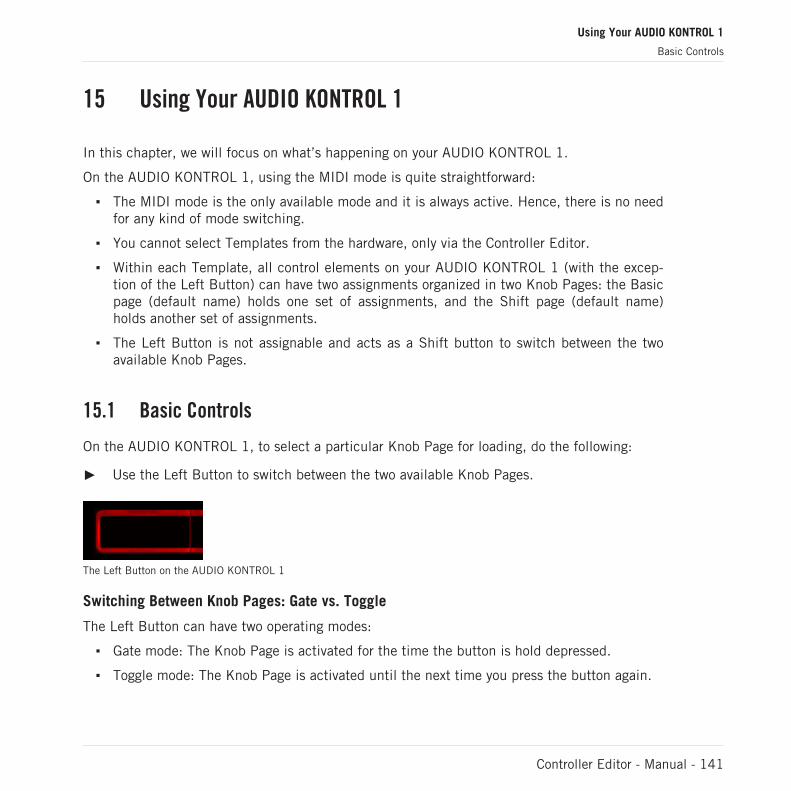
15 Using Your AUDIO KONTROL 1
In this chapter, we will focus on what’s happening on your AUDIO KONTROL 1.
On the AUDIO KONTROL 1, using the MIDI mode is quite straightforward:
▪ The MIDI mode is the only available mode and it is always active. Hence, there is no needfor any kind of mode switching.
▪ You cannot select Templates from the hardware, only via the Controller Editor.
▪ Within each Template, all control elements on your AUDIO KONTROL 1 (with the excep-tion of the Left Button) can have two assignments organized in two Knob Pages: the Basicpage (default name) holds one set of assignments, and the Shift page (default name)holds another set of assignments.
▪ The Left Button is not assignable and acts as a Shift button to switch between the twoavailable Knob Pages.
15.1 Basic Controls
On the AUDIO KONTROL 1, to select a particular Knob Page for loading, do the following:
► Use the Left Button to switch between the two available Knob Pages.
The Left Button on the AUDIO KONTROL 1
Switching Between Knob Pages: Gate vs. Toggle
The Left Button can have two operating modes:
▪ Gate mode: The Knob Page is activated for the time the button is hold depressed.
▪ Toggle mode: The Knob Page is activated until the next time you press the button again.
Using Your AUDIO KONTROL 1
Basic Controls
Controller Editor - Manual - 141

You can choose the desired mode for the Left Button in the Controller Editor. To do this:
1. Check that the AUDIO KONTROL 1 is selected in the Device menu.2. On the Pages page of the Inspector, click the Shift Mode menu and select the desired
mode Gate or Toggle.
15.2 Assignable Control Elements
If you selected the AUDIO KONTROL 1 in the Device menu of the Application Control Bar, thisis what the Hardware area looks like:
The Hardware area representing the AUDIO KONTROL 1.
In this Hardware area, you will notice the orange Knob Page menu at the top, and the red Se-lection Frame on the currently selected control element (Right Button in the picture above).
Using Your AUDIO KONTROL 1
Assignable Control Elements
Controller Editor - Manual - 142
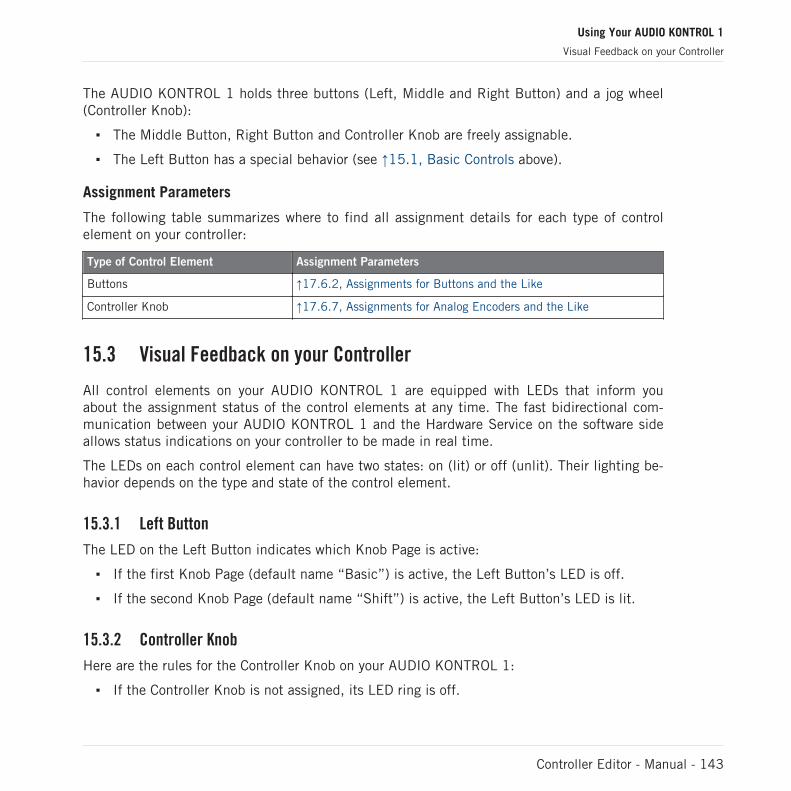
The AUDIO KONTROL 1 holds three buttons (Left, Middle and Right Button) and a jog wheel(Controller Knob):
▪ The Middle Button, Right Button and Controller Knob are freely assignable.
▪ The Left Button has a special behavior (see ↑15.1, Basic Controls above).
Assignment Parameters
The following table summarizes where to find all assignment details for each type of controlelement on your controller:
Type of Control Element Assignment Parameters
Buttons ↑17.6.2, Assignments for Buttons and the Like
Controller Knob ↑17.6.7, Assignments for Analog Encoders and the Like
15.3 Visual Feedback on your Controller
All control elements on your AUDIO KONTROL 1 are equipped with LEDs that inform youabout the assignment status of the control elements at any time. The fast bidirectional com-munication between your AUDIO KONTROL 1 and the Hardware Service on the software sideallows status indications on your controller to be made in real time.
The LEDs on each control element can have two states: on (lit) or off (unlit). Their lighting be-havior depends on the type and state of the control element.
15.3.1 Left Button
The LED on the Left Button indicates which Knob Page is active:
▪ If the first Knob Page (default name “Basic”) is active, the Left Button’s LED is off.
▪ If the second Knob Page (default name “Shift”) is active, the Left Button’s LED is lit.
15.3.2 Controller Knob
Here are the rules for the Controller Knob on your AUDIO KONTROL 1:
▪ If the Controller Knob is not assigned, its LED ring is off.
Using Your AUDIO KONTROL 1
Visual Feedback on your Controller
Controller Editor - Manual - 143

▪ If the Controller Knob is assigned, its LED ring is lit.
15.3.3 Middle and Right Buttons
The following table indicates you the possible states for the LEDs of the Middle and Right But-ton on your AUDIO KONTROL 1:
Button State LED State
Not assigned Off
Assigned – Off state Off
Assigned – On state On
For buttons in Increment mode, the Off state corresponds to the zero value, while the Onstate corresponds to a value greater than zero.
Controlling the Button State
The state of each button can be controlled in two ways — internally via your actions on thebutton, or remotely via MIDI feedback:
▪ In Toggle mode, both controls are enabled: both your actions on the button and the possi-bly incoming MIDI messages are taken into account to update the button state.
▪ In Trigger, Gate, and Increment mode, you can choose which control mode you want touse via the LED On menu located in the Assign page of the Inspector.
For more info on the various button modes, LED On menu, and MIDI feedback mode, see↑17.6.2, Assignments for Buttons and the Like.
Using Your AUDIO KONTROL 1
Visual Feedback on your Controller
Controller Editor - Manual - 144

16 Using Two or More Units of the Same Type
For some NI controllers, the Controller Editor allows you to connect more than one device tothe same computer and use them simultaneously for controlling various MIDI targets. This canbe useful if you wish to control virtual decks of a DJ software or any other application requiringan instant access to many parameters.
The affected NI controllers are listed in the following table:
NI Controller Maximum Number of Devices Used Simultaneously
TRAKTOR KONTROL X1 4
TRAKTOR KONTROL F1 4
Using the Controller Editor, you can create and manage individual Templates, Knob Pages andassignments for each unit. For better distinction of multiple devices, it is necessary to assign aspecific name to each device by choosing from a list of four predefined names (e.g., TraktorKontrol X1 - 1 .. Traktor Kontrol X1 - 4).
By default, all devices have the same name. Therefore you will need to change the names of alldevices except one as soon as you want to use two or more devices simultaneously.
In the following sections, we will use the TRAKTOR KONTROL X1 as example. All instruc-tions also apply to the other controllers in the table above.
16.1 Renaming the Units
We assume here that only one TRAKTOR KONTROL X1 unit is currently connected to yourcomputer. We will rename this unit before connecting an additional one. To rename the con-nected unit, proceed as follows:
1. If the Controller Editor is not currently open, start it.2. In the File menu, select Preferences….
This opens the Preferences window.3. Click the Controller tab on the left to open the Controller page.
Using Two or More Units of the Same Type
Renaming the Units
Controller Editor - Manual - 145

4. In this page, check that the Controller menu at the very top reads Traktor Kontrol X1 - 1.If not, click this menu and select Traktor Kontrol X1 - 1 in the list. The Controller pagenow displays the settings for the connected TRAKTOR KONTROL X1:
The Controller page of the Preferences window showing the settings for the connected TRAKTOR KONTROL X1.
At the bottom of the page, the Device Name menu reads the current name assigned to yourTRAKTOR KONTROL X1. By default, you see the name Traktor Kontrol X1 - 1.
Using Two or More Units of the Same Type
Renaming the Units
Controller Editor - Manual - 146

1. Click the Device Name menu and select another name from the available entries (for ex-ample Traktor Kontrol X1 - 2). Upon your selection, a dialog warns you that you changedthe device name:
2. Follow the instructions in the warning dialog: unplug the unit, then reconnect it. Thewarning dialog disappears.
3. Click OK at the bottom right corner of the Preferences window to close it.4. Connect the second TRAKTOR KONTROL X1 to your computer.
→ You now have your two TRAKTOR KONTROL X1 devices connected to your computer. Youcan switch both to MIDI mode and use them simultaneously as MIDI remote controls.
As you can see, the second TRAKTOR KONTROL X1 still has its factory name. We onlychanged the name of the first TRAKTOR KONTROL X1.
To connect further X1 devices to your computer, please repeat the steps described above (youcan use up to four X1 devices simultaneously).
16.2 Accessing Templates and Knob Pages of a Particular Unit
To see or edit the Templates, Knob Pages and assignments of any TRAKTOR KONTROL X1 de-vice, select its name in the Device menu of the Application Control Bar:
Using Two or More Units of the Same Type
Accessing Templates and Knob Pages of a Particular Unit
Controller Editor - Manual - 147

The Device menu.
You can change the name of your Controllers in the Controller Editor, provided that the rel-evant units are connected. If a unit is not connected to your computer, the settings in theController page of the Preferences window for that unit are grayed out and inactive.
16.3 Resolving Device Conflicts
If you connect an additional TRAKTOR KONTROL X1 with the same name as one of the al-ready connected unit(s), a warning dialog will inform you about the device (name) conflict:
This message will appear if you connect at least two TRAKTOR KONTROL X1 without having renamed your devices before-hand.
Using Two or More Units of the Same Type
Resolving Device Conflicts
Controller Editor - Manual - 148

Please follow the instructions in the dialog: unplug the additional device, rename the originaldevices as described above and then connect the new unit again.
When selecting a name that is already occupied by another TRAKTOR KONTROL X1 unit, Con-troller Editor asks to swap the device name between the device you want to rename and theone that is currently assigned to the selected name. Should the selected name be used by adevice that is currently not connected or the name is not used by another device at all, thechosen name is assigned to the selected controller. If a device name is currently in use, i.e.the device is connected, this is reflected by a leading dot (•) in front of the device name forvisual disctinction. To rename a controller, repeat the actions described above.
Using Two or More Units of the Same Type
Resolving Device Conflicts
Controller Editor - Manual - 149

17 Reference
This chapter systematically describes all the user interface elements of the Controller Editor.The Controller Editor is the “control tower” of your NI controller’s remote control system. Itstores the links between hardware actions (what you do on your NI controller) and MIDI events(what you want to be done within a specific piece of MIDI-capable software or hardware).
17.1 The Application Menu Bar
The Controller Editor menu bar contains three menus: the File menu, the View menu and theHelp menu.
The Application Menu Bar, with its three menus (Windows depicted).
17.1.1 File Menu
The File menu allows you to manage the Configuration files, to tweak the overall behavior ofthe application, and to quit the Controller Editor. The menu contains the following entries:
▪ Open Configuration: Opens a dialog allowing you to select the Configuration file you want toload. The Configuration file contains all data sets used by the Controller Editor. For oneNI controller, the data set contains the list of all Templates, all data in the Templates inthe list, and the index of the currently selected Template — to sum up, the Configurationfile contains everything you can store for use with the Controller Editor. To load a Configu-ration file, select Open Configuration from the File menu, navigate to the desired Configu-ration file in the dialog that appears, and double-click it (or click it, then click Open). Itwill replace the currently loaded configuration.
▪ Save Configuration…: Opens a dialog allowing you to save the current Configuration fileunder another name. In the dialog, type the desired name for the new Configuration file,then click Save.
You can also use the Save Configuration… command as a backup function: Save your Con-figuration file somewhere else (hard drive, USB key…), and you will be able to load itagain.
Reference
The Application Menu Bar
Controller Editor - Manual - 150

There is no Save entry in the File menu. The Controller Editor will remember the currentconfiguration the next time you open the software. Be aware that loading another Configu-ration file will overwrite the current configuration!
▪ Open Template…: Opens a dialog allowing you to select a Template file for loading for thecurrently selected NI controller. The Template will be appended to the Template list inthe Inspector. This command mirrors the command Append located in the Template Editmenu (see ↑17.5.1, Templates Page for more info on the Template list and the TemplateEdit menu).
▪ Preferences…: Opens the Preferences window. This window allows you to tune some glob-al parameters of the Controller Editor. See ↑17.2, The Preferences Window for a descrip-tion of the available parameters.
▪ Exit: Quits the Controller Editor application. Note that all assignments stay active thanksto the NI Hardware Service running in background.
17.1.2 View Menu
The View menu controls the layout of the Controller Editor interface. This menu contains twoentries:
▪ Select Device: This submenu lists all NI controllers currently activated as MIDI remotecontrols. By selecting an entry in this submenu, you choose the NI controller from whichyou want to see/modify the MIDI assignments. The Hardware area along with all Tem-plates / Knob Pages / Pad Pages / assignments are updated accordingly. You can also se-lect a NI controller via the Device menu located on the left in the Application Control Bar(see section ↑17.3.1, Device Menu).
▪ Hide/Show Hardware Device: Hides/shows the Hardware area in the Controller Editor inter-face. This command is equivalent to the Minimize/Expand View button in the ApplicationControl Bar. Showing the Hardware area is useful if you prefer to use the mouse to selecteach control element, in order to see or modify its assignments. The downside is thatshowing the complete user interface requires quite a lot of space on your computerscreen. You can reduce the amount of space Controller Editor requires: select this com-mand to hide the Hardware area and most of the Application Control Bar. With these partsof the user interface hidden, you can still manage your Templates, Knob Pages and PadPages via the Templates and Pages pages of the Inspector. You can even continue work-ing on each assignment by selecting the corresponding control element directly on your NI
Reference
The Application Menu Bar
Controller Editor - Manual - 151

controller, provided that you activated the Touch Select option in File > Preferences >General (see ↑17.2, The Preferences Window). Moreover, you can switch to another NIcontroller via the Select Device entry in this same View menu.
17.1.3 Help Menu
The Help menu gives you access to information that might help you in the use of the ControllerEditor. The menu contains five entries:
▪ Open Manual…: Opens the PDF version of this manual, located in the Controller Editor in-stallation folder.
▪ Open Template Documentation…: Opens the PDF documentation which explains you how touse predefined factory Templates for use with specific Native Instruments and Third Partyproducts.
▪ Launch Service Center…: Launches the NI Service Center. The NI Service Center helps youto activate your Native Instruments product (if activation is required) and afterwards letsyou access product updates. Find more information about the NI Service Center in theseparate Quick Start Guide, located in the Service Center installation folder.
▪ Visit the Knowledge Base…: Opens the Knowledge Base on the Native Instruments websitein your web browser. This web page provides you with useful information about NI prod-ucts, among them the Controller Editor.
▪ Visit Native Instruments on the web…: Opens the Native Instruments home page in yourweb browser.
▪ About…: Opens the About screen (like clicking the Native Instruments logo). This dialogcontains valuable information about the software such as its version number.
17.2 The Preferences Window
The Preferences window holds parameters for the Controller Editor and for the various NI con-trollers.
► To open the Preferences window, click the File menu in the Application Menu Bar andselect Preferences….
Reference
The Application Menu Bar
Controller Editor - Manual - 152

The Preferences window contains two pages, the General page and the Controller page, dis-played by clicking the corresponding tabs:
The Preferences window and its General and Controller tabs on the left (General page displayed).
17.2.1 General Page
The General page offers two options:
▪ Touch Select: If this option is activated, you can select the desired control element direct-ly from your NI controller, the selection of any control element becoming more intuitive.This can be useful to quickly assign the control elements: you don’t need to move yourmouse back and forth repeatedly between the Hardware area (where you select control el-ements) and the Inspector’s Assign page (where you can see or modify the correspondingassignments) — instead, as soon as you touch the desired control element on your NIcontroller, it is automatically selected in the Controller Editor (the red Selection Frame fo-cuses on it) and its assignment is automatically shown in the Assign page of the Inspec-tor. You can now focus on this Assign page on your computer screen, making all selec-tions from your hardware. This can be for example a very efficient way to work on largeseries of assignments. Moreover, this ensures you that you’re really dealing with the con-trol element you plan to use for that particular task. This feature can be also used togeth-er with the Minimize/Expand View button (see section ↑17.3.4, Minimize/Expand ViewButton).
▪ Wrap Template and Page Lists: If activated, the selection jumps to the other end of theTemplate or Pages list whenever you press the Up (or Down) arrow key on your computerkeyboard or the corresponding shortcuts on your controller while the first (or last) entry isselected in the list — in other terms, you “loop” the lists by joining both ends.
Reference
The Preferences Window
Controller Editor - Manual - 153

MASCHINE and KORE controller families: This is also true when using your controller’sshortcuts for selecting Templates and Knob Pages. Note however that the Wrap Templateand Page Lists option does not affect the lists appearing in the corresponding displaymodes of your controller.
17.2.2 Controller Page
The Controller page of the Preferences window allows you to adjust the settings for your variousNI controllers:
The Controller page of the Preferences window, here showing the settings for the MASCHINE MK2 controller.
1. Click the Controller menu at the top. This menu lists all NI controllers installed on yourcomputer.
2. In the drop-down list, select the NI controller whose parameters you want to adjust.
→ Upon your selection, the rest of the Controller page displays the available settings for thatparticular NI controller.
Reference
The Preferences Window
Controller Editor - Manual - 154
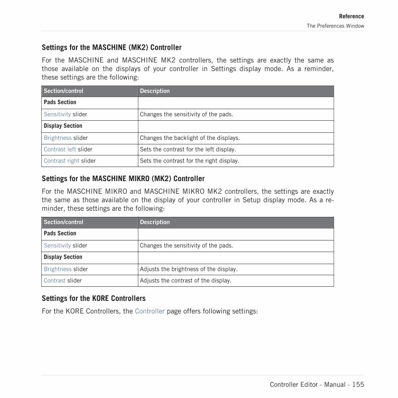
Settings for the MASCHINE (MK2) Controller
For the MASCHINE and MASCHINE MK2 controllers, the settings are exactly the same asthose available on the displays of your controller in Settings display mode. As a reminder,these settings are the following:
Section/control Description
Pads Section
Sensitivity slider Changes the sensitivity of the pads.
Display Section
Brightness slider Changes the backlight of the displays.
Contrast left slider Sets the contrast for the left display.
Contrast right slider Sets the contrast for the right display.
Settings for the MASCHINE MIKRO (MK2) Controller
For the MASCHINE MIKRO and MASCHINE MIKRO MK2 controllers, the settings are exactlythe same as those available on the display of your controller in Setup display mode. As a re-minder, these settings are the following:
Section/control Description
Pads Section
Sensitivity slider Changes the sensitivity of the pads.
Display Section
Brightness slider Adjusts the brightness of the display.
Contrast slider Adjusts the contrast of the display.
Settings for the KORE Controllers
For the KORE Controllers, the Controller page offers following settings:
Reference
The Preferences Window
Controller Editor - Manual - 155
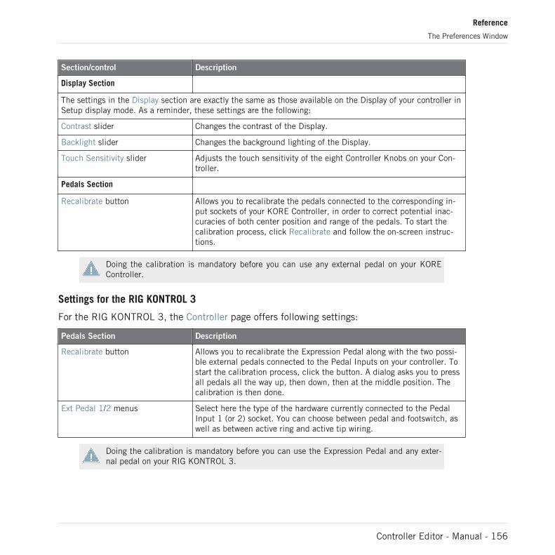
Section/control Description
Display Section
The settings in the Display section are exactly the same as those available on the Display of your controller inSetup display mode. As a reminder, these settings are the following:
Contrast slider Changes the contrast of the Display.
Backlight slider Changes the background lighting of the Display.
Touch Sensitivity slider Adjusts the touch sensitivity of the eight Controller Knobs on your Con-troller.
Pedals Section
Recalibrate button Allows you to recalibrate the pedals connected to the corresponding in-put sockets of your KORE Controller, in order to correct potential inac-curacies of both center position and range of the pedals. To start thecalibration process, click Recalibrate and follow the on-screen instruc-tions.
Doing the calibration is mandatory before you can use any external pedal on your KOREController.
Settings for the RIG KONTROL 3
For the RIG KONTROL 3, the Controller page offers following settings:
Pedals Section Description
Recalibrate button Allows you to recalibrate the Expression Pedal along with the two possi-ble external pedals connected to the Pedal Inputs on your controller. Tostart the calibration process, click the button. A dialog asks you to pressall pedals all the way up, then down, then at the middle position. Thecalibration is then done.
Ext Pedal 1/2 menus Select here the type of the hardware currently connected to the PedalInput 1 (or 2) socket. You can choose between pedal and footswitch, aswell as between active ring and active tip wiring.
Doing the calibration is mandatory before you can use the Expression Pedal and any exter-nal pedal on your RIG KONTROL 3.
Reference
The Preferences Window
Controller Editor - Manual - 156
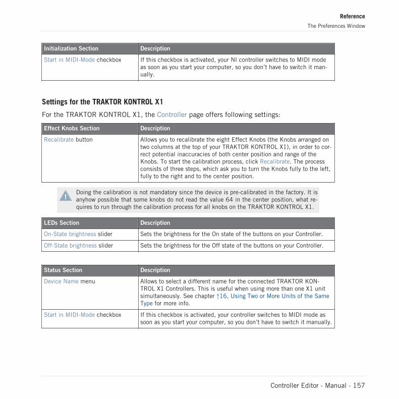
Initialization Section Description
Start in MIDI-Mode checkbox If this checkbox is activated, your NI controller switches to MIDI modeas soon as you start your computer, so you don’t have to switch it man-ually.
Settings for the TRAKTOR KONTROL X1
For the TRAKTOR KONTROL X1, the Controller page offers following settings:
Effect Knobs Section Description
Recalibrate button Allows you to recalibrate the eight Effect Knobs (the Knobs arranged ontwo columns at the top of your TRAKTOR KONTROL X1), in order to cor-rect potential inaccuracies of both center position and range of theKnobs. To start the calibration process, click Recalibrate. The processconsists of three steps, which ask you to turn the Knobs fully to the left,fully to the right and to the center position.
Doing the calibration is not mandatory since the device is pre-calibrated in the factory. It isanyhow possible that some knobs do not read the value 64 in the center position, what re-quires to run through the calibration process for all knobs on the TRAKTOR KONTROL X1.
LEDs Section Description
On-State brightness slider Sets the brightness for the On state of the buttons on your Controller.
Off-State brightness slider Sets the brightness for the Off state of the buttons on your Controller.
Status Section Description
Device Name menu Allows to select a different name for the connected TRAKTOR KON-TROL X1 Controllers. This is useful when using more than one X1 unitsimultaneously. See chapter ↑16, Using Two or More Units of the SameType for more info.
Start in MIDI-Mode checkbox If this checkbox is activated, your controller switches to MIDI mode assoon as you start your computer, so you don’t have to switch it manually.
Reference
The Preferences Window
Controller Editor - Manual - 157

Settings for the TRAKTOR KONTROL F1
For the TRAKTOR KONTROL F1, the Controller page offers following settings:
Knobs Section Description
Recalibrate button Allows you to recalibrate the four FILTER knobs at the top of the F1. Tostart the calibration process, click Recalibrate. The process consists ofthree steps, which ask you to turn the knobs fully to the left, fully to theright and to the center position.
Doing the calibration is not mandatory since the device is pre-calibrated in the factory. It isanyhow possible that some knobs do not read the value 64 in the center position, what re-quires to run through the calibration process for all knobs on the TRAKTOR KONTROL F1.
Faders Section Description
Recalibrate button Allows you to recalibrate the vertical faders. Click Recalibrate to startthe calibration process, then follow the on-screen instructions.
LEDs Section Description
On-State brightness slider Sets the brightness for the On state of the buttons on your Controller.
Off-State brightness slider Sets the brightness for the Off state of the buttons on your Controller.
Status Section Description
Device Name menu Allows to select a different name for the connected TRAKTOR KON-TROL F1 Controllers. This is useful when using more than one F1 unitsimultaneously. See chapter ↑16, Using Two or More Units of the SameType for more info.
Start in MIDI-Mode checkbox If this checkbox is activated, your controller switches to MIDI mode assoon as you start your computer, so you don’t have to switch it manually.
Settings for the TRAKTOR KONTROL S2/S4
For the TRAKTOR KONTROL S2/S4, the Controller page offers following settings:
Reference
The Preferences Window
Controller Editor - Manual - 158

Knobs Section Description
FX Recalibrate button Allows you to recalibrate the FX knobs. Click Recalibrate to start the cal-ibration process, then follow the on-screen instructions.
EQs & Filters Recalibrate button Allows you to recalibrate the EQ and FILTER knobs. Click Recalibrate tostart the calibration process, then follow the on-screen instructions.
Faders Section Description
Vertical Faders Recalibrate button Allows you to recalibrate the vertical faders. Click Recalibrate to startthe calibration process, then follow the on-screen instructions.
Crossfader Recalibrate button Allows you to recalibrate the crossfader. Click Recalibrate to start thecalibration process, then follow the on-screen instructions.
Jogwheels Section Description
Left Recalibrate button Allows you to recalibrate the left jog wheel. Click Recalibrate to start thecalibration process, then follow the on-screen instructions.
Right Recalibrate button Allows you to recalibrate the right jog wheel. Click Recalibrate to startthe calibration process, then follow the on-screen instructions.
Doing the calibration (especially for the jog wheels) is recommended before the first use ofyour S2/S4, as well as after carrying your S4 to another location.
LEDs Section Description
On-State brightness slider Sets the brightness for the On state of the buttons on your Controller.
Off-State brightness slider Sets the brightness for the Off state of the buttons on your Controller.
Footswitch Section (S4 only) Description
Active menu Select here the type of wiring used by the footswitch currently connect-ed to the FOOTSWITCH socket. You can choose between active ring(Ring) and active tip (Tip) wiring.
Reference
The Preferences Window
Controller Editor - Manual - 159
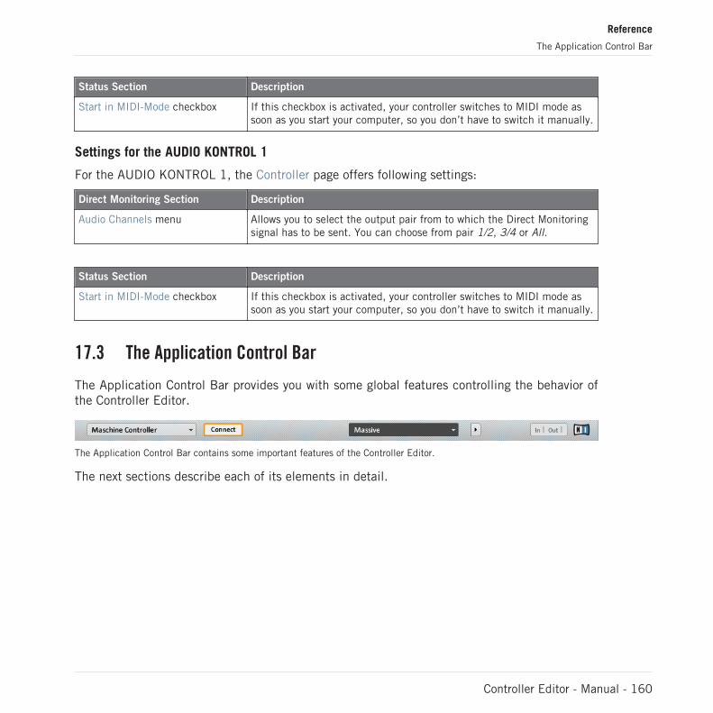
Status Section Description
Start in MIDI-Mode checkbox If this checkbox is activated, your controller switches to MIDI mode assoon as you start your computer, so you don’t have to switch it manually.
Settings for the AUDIO KONTROL 1
For the AUDIO KONTROL 1, the Controller page offers following settings:
Direct Monitoring Section Description
Audio Channels menu Allows you to select the output pair from to which the Direct Monitoringsignal has to be sent. You can choose from pair 1/2, 3/4 or All.
Status Section Description
Start in MIDI-Mode checkbox If this checkbox is activated, your controller switches to MIDI mode assoon as you start your computer, so you don’t have to switch it manually.
17.3 The Application Control Bar
The Application Control Bar provides you with some global features controlling the behavior ofthe Controller Editor.
The Application Control Bar contains some important features of the Controller Editor.
The next sections describe each of its elements in detail.
Reference
The Application Control Bar
Controller Editor - Manual - 160

17.3.1 Device Menu
The Device menu.
The Device menu informs you which NI controller’s assignments you are working on. Further-more, it allows you to switch to another NI controller in order to see and edit its assignments.It is an alternative to the Select Device submenu located in the View menu of the ApplicationMenu Bar. Moreover, all NI controllers currently connected are marked with a leading dot (•)for visual disctinction.
To switch to another NI controller, do the following:
1. Click the Device menu to open a drop-down list containing all MIDI-capable NI control-lers.
2. In the list, select the desired NI controller.The Hardware area is updated accordingly and all Templates / Knob Pages / Pad Pages / as-signments are recalled for the newly selected NI controller.
All parameters and settings displayed in the Controller Editor’s interface refer to the NI con-troller currently selected in this Device menu, with the exception of the MIDI Activity indicatorand the NI Logo, at the far right of the Application Control Bar.
Worth to note is that all NI controllers currently in MIDI mode are still active, no matterwhich controller is displayed in the Controller Editor.
Reference
The Application Control Bar
Controller Editor - Manual - 161
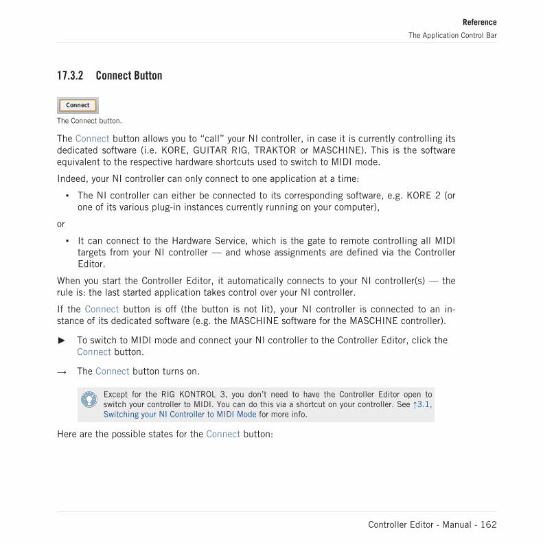
17.3.2 Connect Button
The Connect button.
The Connect button allows you to “call” your NI controller, in case it is currently controlling itsdedicated software (i.e. KORE, GUITAR RIG, TRAKTOR or MASCHINE). This is the softwareequivalent to the respective hardware shortcuts used to switch to MIDI mode.
Indeed, your NI controller can only connect to one application at a time:
▪ The NI controller can either be connected to its corresponding software, e.g. KORE 2 (orone of its various plug-in instances currently running on your computer),
or
▪ It can connect to the Hardware Service, which is the gate to remote controlling all MIDItargets from your NI controller — and whose assignments are defined via the ControllerEditor.
When you start the Controller Editor, it automatically connects to your NI controller(s) — therule is: the last started application takes control over your NI controller.
If the Connect button is off (the button is not lit), your NI controller is connected to an in-stance of its dedicated software (e.g. the MASCHINE software for the MASCHINE controller).
► To switch to MIDI mode and connect your NI controller to the Controller Editor, click theConnect button.
→ The Connect button turns on.
Except for the RIG KONTROL 3, you don’t need to have the Controller Editor open toswitch your controller to MIDI. You can do this via a shortcut on your controller. See ↑3.1,Switching your NI Controller to MIDI Mode for more info.
Here are the possible states for the Connect button:
Reference
The Application Control Bar
Controller Editor - Manual - 162

NI Controller Connect Button
MIDI mode active Lit
MIDI mode inactive Off (click it to switch your controller to MIDI mode)
Not connected / not installed Grayed out (inactive)
To sum up, the Connect button always shows you the state of your NI controller.
17.3.3 Template Select Menu
The Template Select menu allows you to select the desired Template.
The Template Select menu allows you to choose a Template from the list of all available Tem-plates for the NI controller selected in the Device menu. The menu contains all Templates ofyour Template list (in the Inspector’s Templates page).
See ↑4.3.4, Templates for more info on Templates and what they are for.
► To load a particular Template, click the Template Select menu and select the desired en-try from the list.
→ The selected Template is automatically loaded. It replaces the current Template, alongwith all its Knob Pages, Pad Pages (MASCHINE controllers only), and assignments.
For more info on how to create and manage Templates, please refer to ↑17.5.1, TemplatesPage.
17.3.4 Minimize/Expand View Button
The Minimize/Expand View button.
Reference
The Application Control Bar
Controller Editor - Manual - 163

The Minimize/Expand View button shows a little arrow pointing either to the right or to the left.This button allows you to show or hide the Hardware area (and a part of the Application ControlBar) in order to save space on your screen. By reducing the size of the Controller Editor windowon your screen, you get a better overview of other applications.
This button is equivalent to the Hide/Show Hardware Device command found in the Applica-tion Menu Bar’s View menu.
► When the Hardware area is visible, click the Minimize/Expand View button to hide it.
→ The Controller Editor interface shrinks to one single column: The Hardware area disap-pears, the Application Menu Bar and the Inspector remain untouched, whereas the Appli-cation Control Bar only shows this same Minimize/Expand View button, the Template Se-lect menu, a minimized version of the MIDI Activity indicator and the NI Logo.
Reference
The Application Control Bar
Controller Editor - Manual - 164

The Controller Editor in minimized view.
► To show the Hardware area again, click the Minimize/Expand View button again (nowshowing a little arrow to the left).
This feature is very useful in any situation where you do not need the Hardware area, for exam-ple:
▪ If you only want to manage your Templates and Knob Pages / Pad Pages, you only needthe Templates and Pages pages of the Inspector.
Reference
The Application Control Bar
Controller Editor - Manual - 165
▪ If you activated the Touch Select option in Preferences > General > Global Controller Op-tions (see ↑17.2.1, General Page), you can select all control elements directly from yourNI controller; thus, you don’t need the Hardware area anymore and you can continueworking on your assignments in the Inspector.
You can still switch to another NI controller when the Controller Editor is minimized bycalling the Select Device entry in the View menu of the Application Menu Bar!
17.3.5 MIDI Activity Indicator
The MIDI Activity indicator
The MIDI Activity indicator displays incoming (In) and/or outgoing (Out) MIDI data. This canbe useful to check if everything is fine between the Controller Editor and its hardware and soft-ware environment in your setup, and more generally, for any MIDI debugging purpose.
On the MASCHINE and MASCHINE MK2 controllers, you can use the Monitor display modeto see the detailed MIDI message being sent. See ↑5.4.6, Monitor Display Mode (MA-SCHINE) or ↑6.4.6, Monitor Display Mode (MASCHINE MK2) for more info.
17.3.6 NI Logo
The NI Logo
When you click the NI Logo, located on the far right of the Application Control Bar, the Aboutscreen opens.
This About screen provides you with some interesting information about your Controller Editorinstallation, including the version number and the credits.
The About screen can also be opened by selecting the About… entry in the Help menu ofthe Application Menu Bar.
Reference
The Application Control Bar
Controller Editor - Manual - 166

17.4 The Hardware Area
When shown (see ↑17.3.4, Minimize/Expand View Button above), the Hardware area basicallyrepresents the NI controller that you have selected in the Device menu above. The Hardwarearea has two main purposes:
▪ It provides you with a graphical representation of your NI controller, for ease of use.
▪ It allows you to select the Template, Knob Page (except for the RIG KONTROL 3 and theTRAKTOR KONTROL S2), Pad Page (MASCHINE and MASCHINE MIKRO controllers on-ly), and control element(s) that you wish to load or edit. For example, this can be particu-larly useful if your NI controller is not currently connected to your computer. That way,you can prepare your assignments even if the hardware is not currently there.
Pairs of mini buttons in the Hardware area: If mini buttons are not selected when you clickthem, click their Label Field instead!
In addition to the exact representation of your NI controller, the Hardware area holds a few ex-tra graphical elements that extend its usability: the Label Fields, the Selection Frame, theKnob Page area / Knob Page menu (except for the RIG KONTROL 3 and the TRAKTOR KON-TROL S2) and the Pad Page area / Pad Page menu (MASCHINE controllers only). Let’s de-scribe each of these.
17.4.1 Label Fields
Some Label Fields next to control elements in the Hardware area.
For every control element of the Hardware area that can be assigned to some MIDI message,you find a Label Field above or below it. This field mirrors the Label Field located in the upperpart of the Assign page in the Inspector, so that you can see all control elements along withtheir names.
Reference
The Hardware Area
Controller Editor - Manual - 167

If no name has been defined yet for a control element, its Label Field displays by default theMIDI message assigned to that control element.
Like all other assignments properties, these names are of course saved within the Knob Pages /Pad Pages / Templates.
Many of the control elements already have a name on them in the Hardware area: thisname only refers to their original function in their dedicated software (MASCHINE, KORE,TRAKTOR or GUITAR RIG).
17.4.2 Selection Frame
The Selection Frame highlights the control element that is currently focused.
The Selection Frame is a red frame highlighting the currently selected control element. When-ever you select another control element in the Hardware area (or, with the Touch Select optionactivated in the Preferences, on your NI controller), the Selection Frame highlights this controlelement. At the same time, the Assign page in the Inspector shows the assignment propertiesfor that element.
You can select two or more control elements of the same type in the Hardware area forbatch editing: Simply hold [Shift] on your computer keyboard and click the desired controlelements! You can also click and drag your mouse to draw a selection rectangle around sev-eral control elements (only control elements of the same type will be included in the selec-tion).
17.4.3 Knob Page Area and Knob Page Menu
The Knob Page area and Knob Page menu are not available for the RIG KONTROL 3 nor forthe TRAKTOR KONTROL S2.
Reference
The Hardware Area
Controller Editor - Manual - 168

Knob Page Area
The Knob Page area holds all control elements included in a Knob Page (here on the MASCHINE controller).
Inside the Hardware area, an orange frame highlights some of the control elements. This framedefines the Knob Page area, which holds all control elements included in the Knob Pages sys-tem.
As a short reminder: The control elements located in the Knob Page area can have multipleassignments, which are grouped on so-called Knob Pages — with, on each Knob Page, oneassignment for one control element (for a general explanation of the Controller Editor’smapping system, see section ↑4.3, The Mapping System).
Reference
The Hardware Area
Controller Editor - Manual - 169
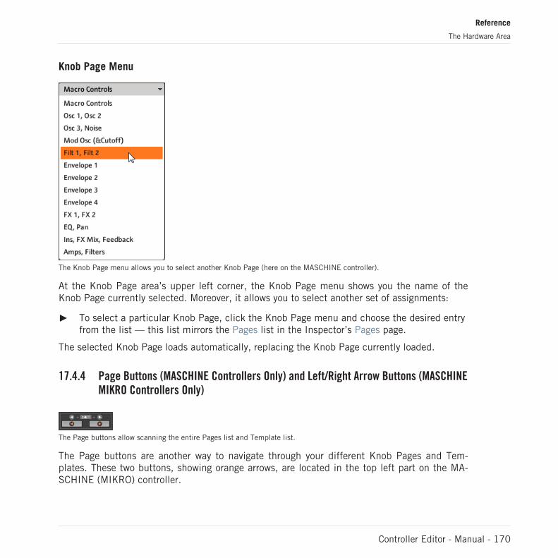
Knob Page Menu
The Knob Page menu allows you to select another Knob Page (here on the MASCHINE controller).
At the Knob Page area’s upper left corner, the Knob Page menu shows you the name of theKnob Page currently selected. Moreover, it allows you to select another set of assignments:
► To select a particular Knob Page, click the Knob Page menu and choose the desired entryfrom the list — this list mirrors the Pages list in the Inspector’s Pages page.
The selected Knob Page loads automatically, replacing the Knob Page currently loaded.
17.4.4 Page Buttons (MASCHINE Controllers Only) and Left/Right Arrow Buttons (MASCHINEMIKRO Controllers Only)
The Page buttons allow scanning the entire Pages list and Template list.
The Page buttons are another way to navigate through your different Knob Pages and Tem-plates. These two buttons, showing orange arrows, are located in the top left part on the MA-SCHINE (MIKRO) controller.
Reference
The Hardware Area
Controller Editor - Manual - 170
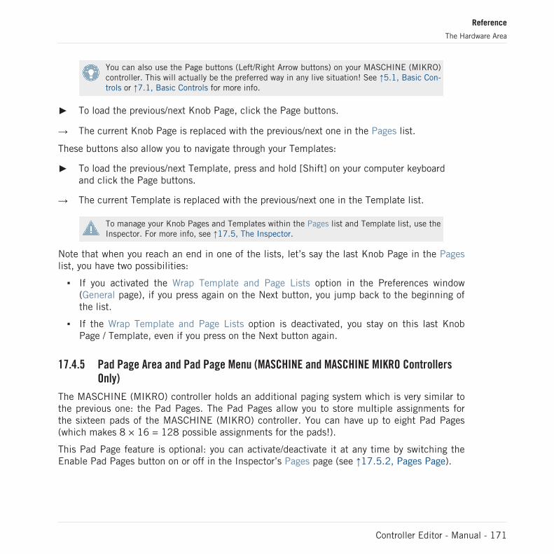
You can also use the Page buttons (Left/Right Arrow buttons) on your MASCHINE (MIKRO)controller. This will actually be the preferred way in any live situation! See ↑5.1, Basic Con-trols or ↑7.1, Basic Controls for more info.
► To load the previous/next Knob Page, click the Page buttons.
→ The current Knob Page is replaced with the previous/next one in the Pages list.
These buttons also allow you to navigate through your Templates:
► To load the previous/next Template, press and hold [Shift] on your computer keyboardand click the Page buttons.
→ The current Template is replaced with the previous/next one in the Template list.
To manage your Knob Pages and Templates within the Pages list and Template list, use theInspector. For more info, see ↑17.5, The Inspector.
Note that when you reach an end in one of the lists, let’s say the last Knob Page in the Pageslist, you have two possibilities:
▪ If you activated the Wrap Template and Page Lists option in the Preferences window(General page), if you press again on the Next button, you jump back to the beginning ofthe list.
▪ If the Wrap Template and Page Lists option is deactivated, you stay on this last KnobPage / Template, even if you press on the Next button again.
17.4.5 Pad Page Area and Pad Page Menu (MASCHINE and MASCHINE MIKRO ControllersOnly)
The MASCHINE (MIKRO) controller holds an additional paging system which is very similar tothe previous one: the Pad Pages. The Pad Pages allow you to store multiple assignments forthe sixteen pads of the MASCHINE (MIKRO) controller. You can have up to eight Pad Pages(which makes 8 × 16 = 128 possible assignments for the pads!).
This Pad Page feature is optional: you can activate/deactivate it at any time by switching theEnable Pad Pages button on or off in the Inspector’s Pages page (see ↑17.5.2, Pages Page).
Reference
The Hardware Area
Controller Editor - Manual - 171
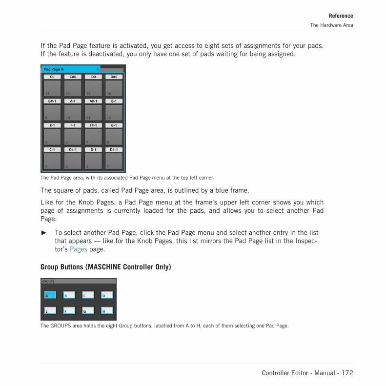
If the Pad Page feature is activated, you get access to eight sets of assignments for your pads.If the feature is deactivated, you only have one set of pads waiting for being assigned.
The Pad Page area, with its associated Pad Page menu at the top left corner.
The square of pads, called Pad Page area, is outlined by a blue frame.
Like for the Knob Pages, a Pad Page menu at the frame’s upper left corner shows you whichpage of assignments is currently loaded for the pads, and allows you to select another PadPage:
► To select another Pad Page, click the Pad Page menu and select another entry in the listthat appears — like for the Knob Pages, this list mirrors the Pad Page list in the Inspec-tor’s Pages page.
Group Buttons (MASCHINE Controller Only)
The GROUPS area holds the eight Group buttons, labelled from A to H, each of them selecting one Pad Page.
Reference
The Hardware Area
Controller Editor - Manual - 172

Like for the Knob Pages with the Page buttons, there is an alternative way of selecting any par-ticular Pad Page: the Group buttons. These buttons are labeled from A to H, and they are lo-cated in the GROUPS area, in the middle left part of the Hardware area.
► Click the desired Group button to select the corresponding Pad Page.
You can also use the Group buttons on your MASCHINE controller. This will actually be thepreferred way in any live situation!
If the Enable Pad Pages button is deactivated in the Pages page of the Inspector, theseeight Group buttons behave like any other control button of the hardware: they are freelyassignable. For more info, please refer to chapter ↑17.5.2, Pages Page in this manual.
17.5 The Inspector
Located on the right of the Controller Editor’s window, the Inspector is THE definitive place toedit and organize your Templates and its possible Knob Pages / Pad Pages, and all your controlassignments. For that reason, the Inspector is always visible.
If you are not sure about the terms “Template,” “Knob Page,” “Pad Page,” etc., read sec-tion ↑4.3, The Mapping System again, where these basic concepts are explained.
As we already mentioned, the basic mapping workflow practically dives into the assignment hi-erarchy. Let’s quickly look at it again, focusing on the Controller Editor window:
1. From the Application Control Bar’s Device menu, select the NI controller which you wantto work with. If you have only one Controller installed, it is automatically selected.
2. Choose a Template. This can be done for example via the Template Select menu in theApplication Control Bar or via the Templates page of the Inspector (see below). As theTemplate loads, all its included (possible) Knob Pages, (possible) Pad Pages and assign-ments are loaded.
3. If the control element that you want to edit is located within the Knob Page area, you alsohave to select the desired Knob Page; if your control element is a pad on the MASCHINEcontrollers and if the Pad Pages feature is activated, you have to select the desired Pad
Reference
The Inspector
Controller Editor - Manual - 173

Page. This can be done either via the Knob Page (or Pad Page) menu, or via the Previous/Next (or Group) buttons, or via the Pages page of the Inspector (see below). If the controlelement is somewhere else on the NI controller, skip this step.
If you only want to use the assignments as they are, that’s all. But if you want to check theassignments or modify them, you then follow the next steps:
1. Put the focus on the control element that you want to edit. This can be done either in theHardware area or directly on your Controller (if the Touch Select option is activated in theGeneral page of the Preferences window) by clicking/touching the desired control ele-ment.
2. Go to the Assign page of the Inspector (see below) and tweak the assignment propertiesfor this control element.
Pages in the Inspector
The Inspector is divided into three pages, each of them taking care of a specific level in theController Editor’s mapping system:
▪ The Templates page allows you to manage your Templates.
▪ The Pages page allows you to organize your Knob Pages. This page is not available for theRIG KONTROL 3 nor for the TRAKTOR KONTROL S2. When working with the MASCHINEcontrollers, this Pages page also allows you to activate and organize the Pad Pages.
▪ Last but not least, the Assign page allows you to edit very precisely the MIDI assignmentfor the control element currently selected in the Hardware area.
Let’s describe each of these three pages thoroughly. We will follow the usual workflow, startingwith the Templates, then look at the Knob Pages (and Pad Pages), and finally describing alldetails of the assignments.
17.5.1 Templates Page
The Templates page allows you to select and manage your Templates. The Templates can beused to store a whole set of assignments, Knob Pages and Pad Pages, for example for a specif-ic use: a particular hardware instrument, a particular software configuration for a live set, aparticular song of your set, etc.
► To show the Templates page, click the Templates tab at the top of the Inspector.
Reference
The Inspector
Controller Editor - Manual - 174
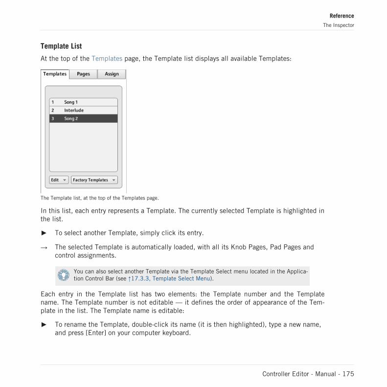
Template List
At the top of the Templates page, the Template list displays all available Templates:
The Template list, at the top of the Templates page.
In this list, each entry represents a Template. The currently selected Template is highlighted inthe list.
► To select another Template, simply click its entry.
→ The selected Template is automatically loaded, with all its Knob Pages, Pad Pages andcontrol assignments.
You can also select another Template via the Template Select menu located in the Applica-tion Control Bar (see ↑17.3.3, Template Select Menu).
Each entry in the Template list has two elements: the Template number and the Templatename. The Template number is not editable — it defines the order of appearance of the Tem-plate in the list. The Template name is editable:
► To rename the Template, double-click its name (it is then highlighted), type a new name,and press [Enter] on your computer keyboard.
Reference
The Inspector
Controller Editor - Manual - 175

For your convenience, you can reorder the Templates in the list by drag and drop. Reorderingyour Templates can be useful if you plan to use several Templates for a live performance andyou need to have them available in a specific order. On the MASCHINE and KORE controllers,you can even switch to the previous/next Template using the following methods:
► MASCHINE controller: Use the Page buttons while holding SHIFT depressed, or switch tothe Template display mode (see ↑5.4.4, Knob Pages Display Mode).
► KORE Controller: Switch to the Templates display mode (see ↑9.4.6, Templates DisplayMode).
On the RIG KONTROL 3, TRAKTOR KONTROL X1/F1, TRAKTOR KONTROL S2/S4, andAUDIO KONTROL 1, there is no way to switch between Templates from your controller.
If the number of Templates is too big to fit in the displayed Template list, a scrollbar appearson the right to navigate through the list.
Edit Menu
Located below the Template list, the Edit menu gives you access to important managementfunctions. To access any of these functions, click the menu and select the desired entry:
The Edit menu below the Template list.
The following commands are available:
▪ New: Creates a new default Template. This new Template is appended at the end of thelist. You can have as many Templates as you want in your list.
▪ Append: Opens a dialog allowing you to navigate to the desired Template file on your harddrive to load it. Select the Template file and click OK (or double-click the Template file):the Template will be appended at the end of the list and will automatically be loaded ascurrent Template.
Reference
The Inspector
Controller Editor - Manual - 176

▪ Replace: Opens a dialog allowing you to navigate to the desired Template file on your harddrive to load it. Select the Template file and click OK (or double-click the Template file):the Template will be loaded and replace the currently selected Template in the Templatelist.
▪ Save As: Opens a dialog allowing you to store the selected Template as a file on your harddrive. The original Template remains untouched, while the newly created Template is ap-pended to the Template list and gets automatically selected.
▪ Duplicate: Duplicates the selected Template and insert it into the list at the position be-low.
▪ Delete: Removes the selected Template. The entries below are moved up to fill the gap.
Factory Templates Menu
Next to the Edit menu, the Factory Templates menu allows you to load factory Templates pro-vided with the Controller Editor. To load any Template, click the menu and select the desiredentry:
The Factory Templates menu below the Template list.
The Templates selected in the Factory Templates menu are loaded into your Template listabove. If you modify or delete the Template once it is loaded in the Template list, the fac-tory Template will stay untouched, ready to be loaded again later!
Reference
The Inspector
Controller Editor - Manual - 177

Furthermore, if new factory Templates are available since the last use of the Controller Editor,a little bubble will appear at the upper right corner of the menu indicating the number of newTemplates:
The menu contains two new factory Templates.
Template Properties
There is no Template Properties area for the TRAKTOR KONTROL X1/F1/S2.
The Template Properties area contains settings for the Template selected in the Template list:
The Template Properties on the Templates page (here for the MASCHINE controller).
Depending on the selected controller, you will find in the Template Properties up to three ele-ments: the Pad Velocity Curve menu, the MIDI Port menu and the Host Transport Controlcheckbox. These elements are described in the following paraphraphs.
Pad Velocity Curve menu (MASCHINE Controller Family Only)
The Pad Velocity Curve menu allows you to choose from a list of seven velocity curves that af-fect the behavior of the pads on your controller. A velocity curve defines how the pressure onthe pads will be translated into velocity values. In the Pad Velocity Curve menu, you canchoose between three soft, three hard and one linear curve. The soft curves are boosting lowerpressure values and damping higher pressure values (logarithmic response), the hard curvesare damping lower pressure values and boosting higher pressure values (exponential response).The linear curve will translate pressure values into velocity values proportionally.
Reference
The Inspector
Controller Editor - Manual - 178

MIDI Port menu
For the NI controllers equipped with a MIDI In/Out socket, the MIDI Port menu allows you tospecify whether you want to send the MIDI messages to the internal (virtual) MIDI port or tothe external (physical) MIDI port of your NI controller. When you click this menu, you see twooptions:
▪ Internal: The MIDI messages are routed through the internal MIDI port. This way, they cantarget other MIDI-capable applications running on your computer (provided that these ap-plications are listening to this MIDI port — this has to be set in the target application’spreferences).
▪ External: The MIDI messages are routed through the MIDI output of your NI controller.That way, your Template can target other MIDI-capable hardware devices connected tothe MIDI output socket of your controller.
There is no MIDI Port menu for the MASCHINE MK2 controller. All MIDI messages arerouted through the internal MIDI port.
Host Transport Control (MASCHINE Controller Family Only)
Host Transport Control is a special feature to be used when the MASCHINE software is runningas plug-in in a host environment. It allows you to split the controls on your MASCHINE (MK2)or MASCHINE MIKRO (MK2) controller so that some controls have the regular MASCHINEfunctions, while others control your host. The controls are split as follows:
▪ On one hand, the PLAY, RESTART, Step Backwards, Step Forwards, and ERASE buttonsin the TRANSPORT section of your controller will send MIDI messages as defined in theTemplate.
▪ On the other hand, all other control elements will control the MASCHINE plug-in loadedin your host.
This notably allows you to control the transport functions of your sequencer via MIDI while youcontrol the MASCHINE plug-in with the rest of your controller!
The Host Transport Control feature works only if MASCHINE is running as a plug-in in ahost environment.
Reference
The Inspector
Controller Editor - Manual - 179

The Host Transport Control checkbox.
► Click the Host Transport Control checkbox to enable/disable the Host Transport Controlfeature for the selected Template.
Keep in mind that the Host Transport Control option belongs to the Template Properties,thus you can enable/disable it for each Template individually.
When Host Transport Control is active and your controller is focused on a MASCHINE plug-ininstance in your host enrivonment, the following happens:
▪ On your controller, the PLAY, RESTART, Step Backwards, Step Forwards, and ERASE but-tons are dimmed to indicate that they are in MIDI mode.
▪ All other control elements on your controller have their usual MASCHINE behavior, includ-ing the display(s).
▪ In the Controller Editor, the affected buttons are highlighted in the Hardware area:
Note that if you modify any of the assignments for the affected buttons, your entire con-troller will switch to MIDI mode — simply press SHIFT + MIDI to switch it back to the(split) MASCHINE mode.
17.5.2 Pages Page
The Pages page is not available for the RIG KONTROL 3 nor for the TRAKTOR KON-TROL S2.
The Pages page allows you to select and manage your Knob Pages and Pad Pages.
Reference
The Inspector
Controller Editor - Manual - 180

► To show the Pages page, click the Pages tab at the top of the Inspector.
Remember that, according to the Controller Editor’s mapping system, all operations madein the Pages page affect the Knob Pages or Pad Pages located in the Template that is cur-rently loaded!
The Knob Pages are sets of assignments for the control elements located in the Knob Pagearea of the Hardware area. For example, the Knob Pages can be used to store the assignmentsfor particular patches of your target instrument, or for specific sections (filter section, effectsection, etc.) of your instrument, or for different instruments in your setup.
Pages List
The Pages page has some similarities with the Templates page explained above. Similarly tothe Templates page, the upper part of the Pages page holds a Pages list. This list displays allKnob Pages available in the current Template:
The Pages list, at the top of the Pages page.
In this list, each entry represents a Knob Page. The Knob Page currently loaded is highlighted.
► To select another Knob Page, simply click its entry.
Reference
The Inspector
Controller Editor - Manual - 181

→ The selected Knob Page is automatically loaded, with all its control assignments.
You can also select another Knob Page via the Knob Page menu on the top of the KnobPage area in the Hardware area, or possibly via the Page buttons, both in the Hardwarearea or on your NI controller. See sections ↑17.4.3, Knob Page Area and Knob Page Menuand ↑17.4.4, Page Buttons (MASCHINE Controllers Only) and Left/Right Arrow Buttons(MASCHINE MIKRO Controllers Only) for more info on this.
Each entry in the Pages list consists of a number and a name. The Knob Page’s number is noteditable — it defines the order of appearance of the Knob Page in the list. The Knob Page’sname is editable:
► To rename the Knob Page, double-click its name (it is then highlighted), type a newname, and press [Enter] on your computer keyboard.
Like in the Template list, you can reorder the Knob Pages in the list by drag and drop:
► To move a Knob Page in the list, click its entry, move your mouse vertically while holdingthe mouse button depressed, and release the mouse button at the desired location.
→ The Knob Page takes its new place in the list.
This can be useful in a live situation, for example if you plan to use several Knob Pages fordifferent parts of a song, and you need to have them in a specific order: When they are wellordered, you can easily switch to the previous/next one by using the Page buttons on your NIcontroller (if available).
You cannot reorder Knob Pages for the TRAKTOR KONTROL X1/F1/S4 nor for the AUDIOKONTROL 1.
If the number of Knob Pages is too big to fit in the displayed list, a scrollbar appears on theright to navigate through the list.
Edit Menu (MASCHINE Controller Family and KORE Controllers Only)
Right under the Pages list, the Edit menu grants access to management functions.
► To access any of these functions, click the Edit menu and select the desired entry.
Reference
The Inspector
Controller Editor - Manual - 182

The Edit menu, below the Pages list.
The following commands are available:
▪ New: Creates a new default Knob Page. This new Knob Page is appended at the end ofthe list. You can have as many Knob Pages as you want in your Template.
▪ Duplicate: Duplicates the selected Knob Page and insert it at the next lower position inthe list. This can be useful to generate several Knob Pages with only a few differences,without having to start from scratch each time.
▪ Copy: Stores the selected Knob Page into your operating system’s clipboard. This is veryuseful to move or copy a particular Knob Page to another Template: after having selectedthe desired Knob Page, choose this Copy command, then switch to another Template (us-ing one of the methods described in this manual), go back to the Inspector’s Pages page,in the Pages list select the entry below which you want to insert the copied Knob Page,and use the Paste command (see below).
▪ Paste: Inserts the Knob Page stored in the clipboard below the Knob Page currently se-lected in the list. The inserted Knob Page is then automatically loaded. You can use thiscommand in conjunction with the Copy command described above to transfer Knob Pagesbetween Templates.
▪ Delete: Removes the selected Knob Page. The lower entries will move up and fill the gap.
Shift Mode Menu (TRAKTOR KONTROL X1/F1/S4 and AUDIO KONTROL 1 Only)
Right under the Pages list, the Shift Mode menu allows you to adapt the behavior of the SHIFTbutton used to switch between both Knob Pages available on your controller. Two settings areavailable:
▪ Gate: The Knob Page is activated for the time the button is hold depressed.
▪ Toggle: The Knob Page is activated until the next time you press the button again.
Reference
The Inspector
Controller Editor - Manual - 183

The Pad Pages Functionality (MASCHINE Controller Family Only)
For the MASCHINE (MK2) and MASCHINE MIKRO (MK2) controllers, the lower part of thePages page offers an additional area that allows you to manage your optional Pad Pages.
The Pad Pages are sets of assignments for the sixteen pads of your controller. For example, thePad Pages can be used to store the assignments for various patches of your target instrument,or for different instruments in your setup.
Please refer to section ↑4.3.3, Pad Pages (MASCHINE Controller Family Only) for more infoon the Pad Pages.
The Enable Pad Pages button on the right allows you to activate/deactivate the Pad Pages functionality.
At the top right of this area, you first see the Enable Pad Pages button. This button allows you toactivate/deactivate the Pad Page feature for your controller.
► To activate the Pad Pages, click the Enable Pad Pages button to enable it.
→ The button switches on (blue) and the lower part of the Pages page is activated.
► To deactivate the Pad Pages, click the Enable Pad Pages button again.
→ The button switches off and the lower part of the Pages page becomes grayed out.
While describing the rest of this area we assume that this Enable Pad Pages button is activat-ed…
Below the Enable Pad Pages button, you see the Pad Pages list. This list shows all Pad Pagesavailable in the current Template:
Reference
The Inspector
Controller Editor - Manual - 184

The Pad Pages list, at the bottom of the Pages page.
In this list, each entry represents a Pad Page. The Pad Page currently loaded is highlighted inthe list.
► To select another Pad Page, simply click its entry.
→ The selected Pad Page is automatically loaded, along with its control assignments for thesixteen pads.
You can also select another Pad Page via the Pad Page menu on the top of the Pad Pagearea, as well as via the Group buttons labeled A to H, in the Hardware area or on your MA-SCHINE (MK2) controller. On the MASCHINE MIKRO (MK2) controller, you can hold theGROUP button and press one of the pads 9–16. See section ↑17.4.5, Pad Page Area andPad Page Menu (MASCHINE and MASCHINE MIKRO Controllers Only) for more info onthis.
Each entry in the Pad Pages list has two elements: the Pad Page letter and the Pad Pagename. The Pad Page letter is not editable — it defines the order of appearance of the PadPage in the list. Moreover, it links the Pad Page to the corresponding button on your controller:
▪ The corresponding Group button in the Hardware area and on your MASCHINE (MK2)controller.
▪ The corresponding pad 9–16 in the Hardware area and on your MASCHINE MIKRO (MK2)controller (used together with the GROUP button).
Reference
The Inspector
Controller Editor - Manual - 185

The Pad Page name is editable:
► To rename the Pad Page, double-click its name (it is then highlighted), type a new name,and press [Enter] on your computer keyboard.
Like in the other lists, you can reorder the Pad Pages in the list via drag and drop:
► Click the desired Pad Page in the list, move your mouse vertically while holding themouse button depressed, and release the mouse button at the desired location.
→ The Pad Page takes its new place in the list.
This can be useful in a live situation, for example if you plan to use several Pad Pages for ad-dressing different parts of a song or sequence, and you need to have them in a specific order.
The number of Pad Pages is limited to eight. You’ll notice that your controller mirrors the num-ber of existing Pad Pages: if some slots in the list are empty, the corresponding Group buttons(or pads) are off:
Pad Pages A–G are assigned, Pad Page A is loaded, and there is no Pad Page H (here on the MASCHINE controller).
The Edit menu below the Pad Pages list.
The Edit menu is very similar to the Edit menu found under the Pages list:
Reference
The Inspector
Controller Editor - Manual - 186

▪ New: Creates a new default Pad Page. This new Pad Page is appended at the end of thelist. As mentioned, you can have up to eight Pad Pages in your Template.
▪ Duplicate: Duplicates the selected Pad Page and insert it at the next lower position in thelist. If there are already eight Pad Pages in the Pad Page list, the Duplicate entry is disa-bled.
▪ Copy: Stores the selected Pad Page into your operating system’s clipboard. This is veryuseful to move or copy a particular Pad Page to another Template: after having selectedthe desired Pad Page, choose this Copy command, then switch to another Template (us-ing one of the methods described in this manual), go back to the Inspector’s Pages page,in the Pad Pages list select the Pad Page below which you want to insert the copied PadPage, and use the Paste command (see below).
▪ Paste: Inserts the Pad Page stored in the clipboard below the Pad Page currently selectedin the list. The inserted Pad Page is then automatically loaded. You can use this com-mand in conjunction with the Copy command described above to transfer Pad Pages be-tween Templates. If there are already 8 Pad Pages in the Pad Pages list, the Paste entryis disabled.
▪ Delete: Removes the selected Pad Page. The lower entries will move up and fill the gap. Ifthere is only one Pad Page, it cannot be deleted.
17.5.3 Assign Page
The Assign page allows you to define all necessary MIDI assignment attributes for a particularcontrol element.
► To show the Pages page, click the Pages tab at the top of the Inspector.
Indeed, it displays and allows to modify the assignment attributes for the control element thatis currently selected in the Hardware area — the one on which the red Selection Frame focus-es.
As a reminder, to select a particular control element for editing, do the following:
1. Select a Template.2. Select a Knob/Pad Page if the desired element is located in a Knob/Pad Page.3. Click the control element in the Hardware area or touch it on your NI controller — provid-
ed that the Touch Select option is activated.
Reference
The Inspector
Controller Editor - Manual - 187
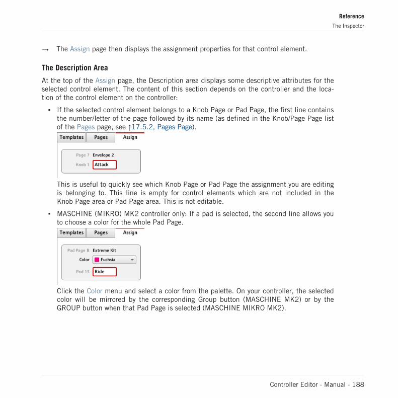
→ The Assign page then displays the assignment properties for that control element.
The Description Area
At the top of the Assign page, the Description area displays some descriptive attributes for theselected control element. The content of this section depends on the controller and the loca-tion of the control element on the controller:
▪ If the selected control element belongs to a Knob Page or Pad Page, the first line containsthe number/letter of the page followed by its name (as defined in the Knob/Page Page listof the Pages page, see ↑17.5.2, Pages Page).
This is useful to quickly see which Knob Page or Pad Page the assignment you are editingis belonging to. This line is empty for control elements which are not included in theKnob Page area or Pad Page area. This is not editable.
▪ MASCHINE (MIKRO) MK2 controller only: If a pad is selected, the second line allows youto choose a color for the whole Pad Page.
Click the Color menu and select a color from the palette. On your controller, the selectedcolor will be mirrored by the corresponding Group button (MASCHINE MK2) or by theGROUP button when that Pad Page is selected (MASCHINE MIKRO MK2).
Reference
The Inspector
Controller Editor - Manual - 188

▪ The last (or only) line displays on the left the element description, its “name” referring toits original function in its dedicated software, which is for info only. On the right, it dis-plays the Label Field, which holds its user-definable name.
► To modify the name in the Label Field, click it, type a new name and press [Enter] onyour computer keyboard.
→ Both Label Fields (in the Assign page and in the Hardware area) are updated accordingly.For particular control elements of some NI controllers, the name will also appear in thecontroller’s hardware display(s).
If no name has been defined yet for a control element, its Label Field displays by default theMIDI message assigned to this control element.
To reset a Label Field to its default name, clear the field, then press the [Enter] key onyour computer keyboard.
The Definition Area
Below the Description area, the assignment properties explicitly define what has to be sentwhen you actuate the control element on your NI controller: this is called the Definition area.
The properties in the Definition area differ according to the type of control element currentlyselected: since a button, a knob, and a pad don’t have the same physical properties and be-havior, they won’t be able to trigger the same types of MIDI events.
Furthermore, some control elements on certain NI controller can respond to two different ac-tions:
▪ MASCHINE Controller Family: The pads can be hit, but they can also be pressed. Further-more, on the MASCHINE MIKRO, MASCHINE MK2, and MASCHINE MIKRO MK2 con-trollers, the Control encoder can be both turned and pushed.
▪ KORE Controllers: The Controller Knobs are touch-sensitive: they can be turned like anyusual knob, but they can also be touched.
Reference
The Inspector
Controller Editor - Manual - 189

▪ TRAKTOR KONTROL X1: The Push Encoders can be both turned and pushed.
▪ TRAKTOR KONTROL F1: The encoder knob can be both turned and pushed.
▪ TRAKTOR KONTROL S2/S4: The encoders (LOOP MOVE and LOOP SIZE on the Decks,BROWSE on the Mixer) and the jog wheels can be both turned and pushed.
For these double function elements, the two possible actions lead to two possible MIDI mes-sages. Hence, the Definition area displays two corresponding Action tabs, each of them allow-ing to define the MIDI event for one specific action.
For control elements with only one function, the Definition area does not display any tabs, butdirectly displays the assignment properties for the unique MIDI assignment of this control ele-ment.
The top of the Definition area differs if the control element has one or two functions.
In the picture above, on the left you see the assignment for a button, and on the right you seethe two Action tabs (labelled Hit and Press) for a pad on the MASCHINE controller.
The label on each tab indicates the particular hardware action that will trigger the MIDI mes-sage specified in that page: for example, for a Controller Knob on the KORE Controller, you willfind the Turn tab and the Touch tab instead.
The next section will describe each and every settings available for the assignments of MIDImessages.
17.6 MIDI Message Parameters
You will find here the description of all possible parameters to be found within the Definitionarea of the Inspector’s Assign page, for all kinds of control elements and all NI controllers.
We will first give a few general rules valid for various sorts of control elements.
We will then detail the MIDI messages settings for each sort of control elements.
Reference
MIDI Message Parameters
Controller Editor - Manual - 190

17.6.1 MIDI Message Types – Type Menu
For all control elements, the assignment definition starts with the same menu: the Type menu,at the very top of the Definition area.
The Type menu specifies the type of MIDI message that has to be sent upon action on this control element. Depending onthe type of hardware control element, the entries in this menu will differ (for example, sending a “play” command from aknob wouldn’t make much sense).
The Type menu allows you to choose from various MIDI message types.
► To select a MIDI message type, click the Type menu and select the desired entry fromthe list.
All other parameters displayed in the Assign page’s Definition area depend both on the type ofcontrol element that you are working on, and on the MIDI message type selected in this Typemenu.
Below is a list of all possible MIDI message types to be found in the Type menu.
Keep in mind that depending on the selected control element, some of them are not availa-ble in its Type menu. In the next sections, we will explain the particularities for each con-trol element available on your NI controller.
Reference
MIDI Message Parameters
Controller Editor - Manual - 191

▪ Note: Sends a MIDI Note On/Off message. This message is sent over a specific MIDI chan-nel set by the Channel parameter (range from 1 to 16, 1 by default). It tells your target toplay or stop the MIDI Note specified via the Note parameter (range from C-2 to G8). Themessage also defines the velocity at which the note is played. This velocity is specified invarious ways, depending on the type of the selected control element (see next sections).
▪ Note (Relative): Sends a MIDI Note On message. This message type is actually made forspecific situations where some function in the target software must be triggered by an in-coming Note On event. This can be the case, for example, for scrolling through lists,where the target software only offers a trigger control for selecting the “next” or the “pre-vious” item in the list. With this Note (Relative) message type, you can use for example ajog wheel on your TRAKTOR KONTROL S4 or a Push Encoder on your TRAKTOR KON-TROL X1 to scroll through the list in the target software. The message is sent over a spe-cific MIDI channel set by the Channel parameter (range from 1 to 16, 1 by default). Twoadditional Note parameters define the MIDI note numbers triggered when turning the con-trol counter-clockwise and clockwise, respectively (both ranges from 0 to 127, that isfrom MIDI Note C-1 to G9).
▪ Control Change: Sends a MIDI Control Change message. This message is sent over a spe-cific MIDI channel set by the Channel parameter (range from 1 to 16, 1 by default). Thismessage tells your target to change the value of a specific continuous controller — con-trolling for example some effect’s depth in your music application. The continuous con-troller (CC) number is specified via the Number parameter (range from 0 to 127). The val-ues to be sent for that controller are specified in various ways, depending on the type ofthe selected control element (see next sections).
▪ Poly Pressure: Sends a MIDI Poly Pressure message (also called Polyphonic Aftertouch).This message is sent over a specific MIDI channel set by the Channel parameter (rangefrom 1 to 16, 1 by default). It specifies the pressure at which a particular MIDI note isheld down. The MIDI note is specified via the Note parameter. The pressure values to besent are specified in various ways, depending on the type of the selected control element(see next sections).
▪ Channel Pressure: Sends a MIDI Channel Pressure message (also called Channel After-touch). This message is sent over a specific MIDI channel set by the Channel parameter(range from 1 to 16, 1 by default). It specifies a common pressure at which all notes ofthe MIDI channel are held down. The pressure values to be sent are specified in variousways, depending on the type of the selected control element (see next sections).
Reference
MIDI Message Parameters
Controller Editor - Manual - 192

▪ Program Change: Sends a MIDI Program Change message. This message is sent over aspecific MIDI channel set by the Channel parameter (range from 1 to 16, 1 by default). Ittells the target to switch to another program (or patch, preset…). The program number tobe sent can be specified in various ways, depending on the type of the selected controlelement (see next sections).
▪ Pitchbend: Sends a MIDI Pitchbend message. This message is sent over a specific MIDIchannel set by the Channel parameter (range from 1 to 16, 1 by default). It is used tocontrol the Pitchbend Wheel (and anything that would respond to the MIDI Pitchbendmessage in your target). This is quite similar to a Control Change message, but for histori-cal and practical reasons (on most hardware controllers/keyboards, the Pitchbend wheel isa very specific control element), the Pitchbend is a distinct message in the MIDI specifi-cations.
▪ Start: Sends a MIDI Start Song message. As its name implies, this message should be un-derstood by your sequencer as a Start command. This message tells your sequencer tostart playback of the song/sequence from the beginning. There is no parameter needed forthis message.
▪ Stop: Sends a MIDI Stop Song message. This should be understood by your sequencer asa Stop command. This message tells your sequencer to pause the playback of the song/sequence at its current position. There is no parameter needed for this message.
▪ Continue: Sends a MIDI Continue Song message. As its name implies, this messageshould be understood by your sequencer as a Continue command. This message tells yourtarget to start playback of the song/sequence from the current position. There is no pa-rameter needed for this message.
▪ Song Position: Sends a MIDI Song Position message. This message tells your target to cuethe playback to a specific position in the song/sequence. Note that it does not start theplayback itself. The message is implemented in a specific way that allows you to switchbetween 2 positions in the song or sequence. The position(s) in the song or sequence canbe specified in various ways, depending on the type of control element (see below). Theposition in the song is counted in MIDI beats.
▪ MCU V-Pot: Emulates one of the Mackie Control’s 8 V-Pots.
▪ MCU Channel: Emulates one of the Mackie Control’s 8 channel faders.
▪ MCU Master: Emulates the master fader of the Mackie Control.
Reference
MIDI Message Parameters
Controller Editor - Manual - 193
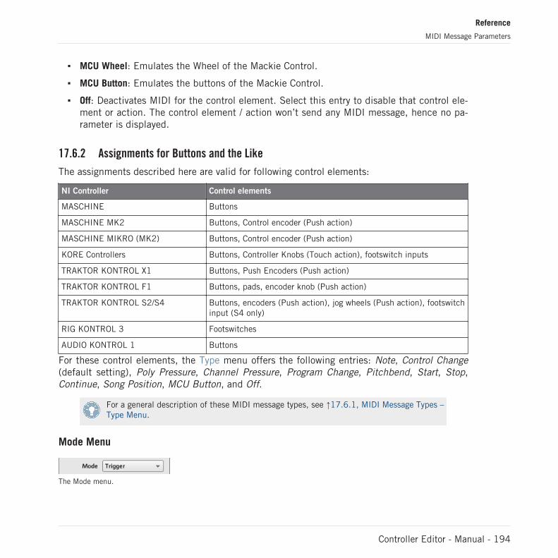
▪ MCU Wheel: Emulates the Wheel of the Mackie Control.
▪ MCU Button: Emulates the buttons of the Mackie Control.
▪ Off: Deactivates MIDI for the control element. Select this entry to disable that control ele-ment or action. The control element / action won’t send any MIDI message, hence no pa-rameter is displayed.
17.6.2 Assignments for Buttons and the Like
The assignments described here are valid for following control elements:
NI Controller Control elements
MASCHINE Buttons
MASCHINE MK2 Buttons, Control encoder (Push action)
MASCHINE MIKRO (MK2) Buttons, Control encoder (Push action)
KORE Controllers Buttons, Controller Knobs (Touch action), footswitch inputs
TRAKTOR KONTROL X1 Buttons, Push Encoders (Push action)
TRAKTOR KONTROL F1 Buttons, pads, encoder knob (Push action)
TRAKTOR KONTROL S2/S4 Buttons, encoders (Push action), jog wheels (Push action), footswitchinput (S4 only)
RIG KONTROL 3 Footswitches
AUDIO KONTROL 1 Buttons
For these control elements, the Type menu offers the following entries: Note, Control Change(default setting), Poly Pressure, Channel Pressure, Program Change, Pitchbend, Start, Stop,Continue, Song Position, MCU Button, and Off.
For a general description of these MIDI message types, see ↑17.6.1, MIDI Message Types –Type Menu.
Mode Menu
The Mode menu.
Reference
MIDI Message Parameters
Controller Editor - Manual - 194

For the button-like control elements listed in the above table, and only for some of the MIDImessage types available for these control elements, you can choose from different behaviorsfor the way the data is sent. This is controlled by the Mode menu. This menu can have up tofour entries, depending on the message type that you have selected in the Type menu. Here isthe list of all possible entries:
▪ Toggle: In this mode, the control element has two states, On and Off. If you press once, itswitches to the On state — if you press again, it switches to the Off state. This can beuseful for example for activating some effect, then deactivating it later. This is usually thedefault mode. In this mode, you find two numeric fields: Off Value defines the value forthe Off state (from 0 to 127, 0 by default), and On Value defines the value for the Onstate (0 to 127, 127 by default).
▪ Gate: In this mode, the element switches to the On state for the time it is held depressed.As soon as you release it, it switches back to the Off state. It is similar to the behavior ofa key on a keyboard: the note is played when you hold the key depressed, and the note isswitched off when you release the key. Like in Toggle mode, you find two numeric fields:Value Off defines the value for the Off state (from 0 to 127, 0 by default), and Value Ondefines the value for the On state (0 to 127, 127 by default).
▪ Trigger: In this mode, only one message is sent when you hit the control element. Thereare no On or Off states. For example, this can be useful for switching to another program(preset, patch…) or for triggering one-shot samples (e.g. drum sounds or any other enve-lope-controlled sounds). In this mode, you thus find only one numeric field called Value,defining the value to be sent when you hit the control element. It goes from 0 to 127(127 by default).
▪ Inc (Increment): In Increment mode, each action on the control element increases/de-creases the parameter value. Two numeric fields Range From and To define the min andmax values of the interval, respectively, each of them going from 0 to 127 (by default, 0for the min and 127 for the max). Below, another numeric field called Step defines theincrement to add (or to subtract if negative) each time that you press the button (it goesfrom -127 to 127, with 1 as default value). Finally, the Wrap button allows you to “cycle”the interval: If this button is activated, once the parameter reaches one of its limits, itjumps to the other one upon the next time you hit the control element. If the Wrap buttonis deactivated, the message sent upon the next hit keeps the maximal (or minimal) valuefor the parameter.
Reference
MIDI Message Parameters
Controller Editor - Manual - 195

LED On Menu
The LED On menu.
For all control elements with LEDs and in Trigger, Gate, or Increment mode, a LED On menuallows you to choose from two LED lighting behaviors:
▪ For MIDI In (default): Selects the MIDI feedback mode. In this mode, the LED behavior iscontrolled by the MIDI target via a MIDI feedback channel. The MIDI target sends a MIDImessage back to the controller to define the LED’s state. This control mode notably allowsthe button LED to be always reflecting the current state of the target’s parameter, even ifyou changed this parameter via another way (e.g. with your mouse or via a keyboard short-cut in the target software). For this to work, you have to define in your target the MIDImessage to be sent accordingly.
▪ For MIDI Out: Selects the internal control mode. In this mode, the LED behavior solely de-pends on your actions on the button.
When the control element is set to Toggle mode, the LED On menu is not available becauseboth behaviors are used — the LED reacts both to your actions and to the (possibly) incom-ing MIDI feedback messages.
Action On Menu
For the Toggle, Trigger, and Increment modes, an Action on menu at the bottom of the Defini-tion area allows you to choose when the message has to be sent.
The Action on menu.
The two options proposed by the Action on menu are:
▪ Down (default setting): The message is sent when the button is switched to the Downstate (i.e. when you hit the button)
▪ Up: The message is sent when the button is switched to the Up state (i.e. when you re-lease the button).
Reference
MIDI Message Parameters
Controller Editor - Manual - 196

When the control element is set to Gate mode, this menu is not available — it wouldn’tmake sense, since both Down and Up state already define the Values On and Off to besent.
Color Control
The parameters described here are valid for following control elements only:
NI Controller Control elements
TRAKTOR KONTROL F1 Pads
MASCHINE MK2 Pads, Group buttons (A–H)
MASCHINE MIKRO MK2 Pads, GROUP button
For these control elements, you can define which color(s) should be used for the On and Offstates. This is done via the menus located at the bottom of the Definition area.
The Color Mode menu allows you to choose from three coloring modes:
The Color Mode menu.
These modes are available:
▪ Single: You can choose a color that will be used bright and dimmed for the On and Offstates, respectively. The Color Value menu below allows you to choose this color from thesixteen colors available in the picker.
Reference
MIDI Message Parameters
Controller Editor - Manual - 197

▪ Dual: You can choose a color for the On state and another color for the Off state. Bothcolors will be used at full brightness. The Color On and Color Off menus allow you tochoose both colors from color pickers.
▪ HSB (Hue, Brightness, Saturation): This mode is only available when the pad’s state iscontrolled via MIDI feedback — in other terms, when the pad is in Toggle mode or whenFor MIDI In is selected in the LED On menu (see above). In HSB mode, you can preciselydefine from within your MIDI target which color the pad will use. Hence, in this modethere is no color picker available in the Assign tab.
When the pad is in HSB mode, the Hue, Brightness, and Saturation levels are sent via MIDI tothe controller using the pad’s assigned CC or Note. The MIDI channel used to transmit thosemessages will determine its intent. For example, for a pad assigned to MIDI CC 9, you could:
▪ Send the CC 9 value 127 on channel 3 to set the pad to full brightness.
▪ Send the CC 9 value 16 on channel 1 to set the pad’s color to yellow.
For the TRAKTOR KONTROL F1, the following table lists the MIDI channels used to define thepads’ colors on the four simultaneously available F1 devices:
Parameter MIDI Values Device 1 (default) Device 2 * Device 3 * Device 4 *
Hue 0–127 Channel 1 Channel 4 Channel 7 Channel 10
Saturation 0–127 Channel 2 Channel 5 Channel 8 Channel 11
Brightness 0–127 Channel 3 Channel 6 Channel 9 Channel 12
* These channels will be used when two or more devices are connected to your computer. Forexample, if two TRAKTOR KONTROL F1 units are connected, the unit named “Traktor KontrolF1 - 2” will receive HSB parameters on channels 4–6.
For more info on using two or more F1 simultaneously, please refer to chapter ↑16, UsingTwo or More Units of the Same Type.
▪ For the MASCHINE MK2 and MASCHINE MIKRO MK2 controllers, only channels 1–3 areused in the table above.
Reference
MIDI Message Parameters
Controller Editor - Manual - 198

Please note that updating the control elements’ colors via HSB mode at a very high ratecan lead to MIDI bus overload, making your controller temporarily unresponsive! This is alimitation of the MIDI protocol architecture. If this happens, decrease the amount of HSBmessages sent to your controller.
17.6.3 Assignments for the Pads – Hit Action
The assignments described here are valid for the pads of the whole MASCHINE controller fami-ly (MASCHINE, MASCHINE MK2, MASCHINE MIKRO, MASCHINE MIKRO MK2). The Hit ac-tion on a pad is very similar to actuating a button (see ↑17.6.2, Assignments for Buttons andthe Like above).
The only differences between hitting a pad and pressing a button are the following:
▪ The Pitchbend entry is not available in the Type menu.
However, you can control the Pitchbend via the Press action of the same pad. This allowsyou to create a very intuitive tuning control: With the Hit action of the pad triggering aMIDI Note, you can then detune this note by varying the pressure that you’re applying tothe pad!
▪ There is no Action on menu.
Additionally, the pads of the MASCHINE MK2 and MASCHINE MIKRO MK2 controllers areequipped with multicolor LEDs. You can define which color will be used for each pad state.Please refer to section ↑17.6.2, Assignments for Buttons and the Like above for more info onthis.
17.6.4 Assignments for Knobs and the Like
These virtually continuous control elements are characterized by a physically limited range.
The assignments described here are valid for following control elements:
NI Controller Control elements
KORE Controllers Pedal input(s)
TRAKTOR KONTROL X1 FX Knobs
TRAKTOR KONTROL F1 FILTER knobs, vertical faders
Reference
MIDI Message Parameters
Controller Editor - Manual - 199

NI Controller Control elements
TRAKTOR KONTROL S2/S4 Knobs (FX, Mixer), vertical faders (TEMPO, channels), crossfader
RIG KONTROL 3 Expression Pedal, pedal inputs
For these control elements, the Type menu offers the following entries: Control Change (defaultsetting), Poly Pressure, Channel Pressure, Program Change, Pitchbend, MCU Channel, MCUMaster, and Off.
For a general description of these MIDI message types, see ↑17.6.1, MIDI Message Types –Type Menu.
For Control Change, Poly Pressure, Channel Pressure, Program Change, and Pitchbend, twonumeric fields labeled Range From and To define the min and max values of the interval, re-spectively. Both numeric fields go from 0 to 127 (by default, 0 for the min and 127 for themax), except for the type Pitchbend, for which they go from -100.0 % to 100.0 %.
17.6.5 Assignments for the Pads – Press Action
The assignments described here are valid for the pads of the whole MASCHINE controller fami-ly (MASCHINE, MASCHINE MK2, MASCHINE MIKRO, MASCHINE MIKRO MK2). The Pressaction on a pad (i.e. maintaining a continuous pression on the pad) is quite similar to actuat-ing a knob (see ↑17.6.4, Assignments for Knobs and the Like above).
The Type menu offers the following entries: Note, Control Change, Poly Pressure (default set-ting), Channel Pressure, Pitchbend (very useful for bending the tuning of sounds by pressure!),and Off.
For a general description of these MIDI message types, see ↑17.6.1, MIDI Message Types –Type Menu.
The types Control Change, Poly Pressure, Channel Pressure, and Pitchbend provide the sameparameters as with knobs: two numeric fields labeled Range From and To define the min andmax values of the interval, respectively. Both numeric fields go from 0 to 127 (by default, 0for the min and 127 for the max), except for the type Pitchbend, for which they go from-100.0 % to 100.0 %.
For the type Note, you have instead following parameters:
▪ Value: Sets the velocity of the note to be played.
Reference
MIDI Message Parameters
Controller Editor - Manual - 200

▪ Threshold Off and On: Define the pressure threshold above (below) which the Note On (Off)message is sent. The Threshold Off value should always be smaller than the Threshold Onvalue (have you ever considered stopping a note before playing it?). Both parametersrange from 0 % to 100 % (as a ratio with the maximum pressure).
As you can see, the settings for the Press action on a pad are quite similar to those of the usu-al knobs. Here is a list of the differences:
▪ The Note type is added — and, for that, the on and off thresholds are needed.
▪ Program Change is not available because it would not be controllable.
17.6.6 Assignments for Digital Encoders and the Like
With “encoder” we mean a rotary, virtually continuous control element characterized by anendless range.
The assignments described here are valid for following control elements:
NI Controller Control elements
MASCHINE MK2 Control encoder
MASCHINE MIKRO (MK2) Control encoder
KORE Controllers Scrollwheel
TRAKTOR KONTROL X1 Push Encoders (Turn action)
TRAKTOR KONTROL F1 Encoder knob (Turn action)
TRAKTOR KONTROL S2/S4 Encoders (Turn action), jog wheels (Turn action)
For these control elements, the Type menu offers the following entries: Note (Relative), ControlChange (default setting), Poly Pressure, Channel Pressure, Program Change, Song Position,MCU Wheel, and Off.
For a general description of these MIDI message types, see ↑17.6.1, MIDI Message Types –Type Menu.
For all types except Note (Relative), Control Change and MCU Wheel, you find following pa-rameters:
Reference
MIDI Message Parameters
Controller Editor - Manual - 201

▪ Two numeric fields labeled Range From and To define the min and max values of the in-terval, respectively. Both numeric fields go from 0 to 127 (by default, 0 for the min and127 for the max).
▪ A numeric field Step defines the increment to add (or to subtract if negative) for eachstep of control element (it goes from -128 to 127, with 1 as default value).
▪ The Wrap button allows you to “cycle” the interval: If this button is activated, once theparameter reaches one of its limits, it jumps to the other one upon the next movement ofthe encoder. If the Wrap button is deactivated, the message sent upon the next movementkeeps the maximal (or minimal) value for the parameter.
▪ S2/S4 jog wheels only: A Tick numeric field allows you to reduce the transmission sensi-tivity in order to counterbalance the high number of counts per revolution, which is spe-cific to this control element. This parameter goes from 20 to 1000.
For the S2/S4 jog wheels, the Step parameter ranges from -32 to 31 only.
Control Change
For the type Control Change, a Mode menu allows you to select between three operatingmodes:
▪ Absolute: In this mode the control element sends absolute values. Its parameters are thesame as those described above: two numeric fields Range From and To, a numeric fieldStep and a Wrap button (see above).
▪ Relative: In this mode, the sent message is in a +1/-1 fashion — actually 1/127, which isthen understood by the target software as +1/-1 in that case. This allows the control ele-ment to set the new Control Change value relatively to its current value. There is only oneparameter called Step which defines the increment to use. Increase the Step value to trig-ger greater jumps in the target parameter value. If you choose a negative value for Step,the control will be inverted.
▪ Relative (Offset): This mode is similar to the Relative mode explained above, with the dif-ference that here the values sent for the “+1” and “-1” messages are 65 and 63, respec-tively — in other terms, they are centered around 64 instead of 0. This is well suited forsome particular software implementations. As in Relative mode, a Step parameter definesthe increment to use.
Reference
MIDI Message Parameters
Controller Editor - Manual - 202

The appropriate mode mostly depends on the requirements of your target! Please refer toyour target’s documentation to know which mode is best suited.
Note (Relative)
For the type Note (Relative), two Note parameters define the MIDI note numbers triggeredwhen turning the control counter-clockwise and clockwise, respectively (both ranges from 0 to127, that is from MIDI Note C-1 to G9). See section ↑17.6.1, MIDI Message Types – TypeMenu for more info on this message type.
Display Menu (KORE Controllers Only)
For the types Control Change (Absolute mode only), Poly Pressure, and Channel Pressure, theScrollwheel on the KORE Controllers shows a Display menu: this lets you decide how the pa-rameter should appear on the Display of your controller: with the zero in the middle (bipolar) orat the beginning (unipolar, by default) of the interval. This is up to you, since it depends onwhat you plan to control with this assignment.
The Display menu is only available for the Scrollwheel of the KORE Controllers — since theTRAKTOR KONTROL X1, F1, S2, and S4 do not have any extended display, such a Displaymenu would not make much sense. The same applies for the Control encoder on the MA-SCHINE MIKRO (MK2) and MASCHINE MK2 controllers.
The Program Change type does not offer this parameter, since it is always unipolar (youwouldn’t switch to a negative Program number…). The same applies to the Song Positiontype.
17.6.7 Assignments for Analog Encoders and the Like
In opposition to the digital encoders described above, analog encoders output analog values.The available MIDI message types are slightly different.
The assignments described here are valid for following control elements:
NI Controller Control elements
MASCHINE (MK2) Knobs 1–8 (under the displays)
KORE Controllers Controller Knobs (Turn action)
AUDIO KONTROL 1 Controller Knob
Reference
MIDI Message Parameters
Controller Editor - Manual - 203
For these control elements, the Type menu offers the following entries: Control Change (defaultsetting), Poly Pressure, Channel Pressure, Program Change, Pitchbend, MCU V-Pot, MCUChannel, MCU Master, and Off.
For a general description of these MIDI message types, see ↑17.6.1, MIDI Message Types –Type Menu.
For all types except Control Change and the MCU types, you find following parameters:
▪ Two numeric fields labeled Range From and To define the min and max values of the in-terval, respectively. Both numeric fields go from 0 to 127 (by default, 0 for the min and127 for the max), except for the type Pitchbend, for which they go from -100.0 % to100.0 %.
▪ A numeric field labeled Resolution defines the physical angle on your encoder that isneeded to reach both limits of the interval (as defined by the Range From and To values).Its values go from 30 to 3600 degrees (360 by default, i.e. one full revolution). For exam-ple, if you choose 3600 (degrees), you will need to turn your knob ten times in order to gofrom the minimum value to the maximum value defined by Range.
Control Change
For the type Control Change, a Mode menu allows you to select between three operatingmodes:
▪ Absolute: In this mode the control element sends absolute values. The Range From, To,and Resolution parameters are the same as for the other message types (see above).
▪ Relative: In this mode the sent message is in a +1/-1 fashion — actually 1/127, which isthen understood by the target software as +1/-1 in that case. This allows the control ele-ment to set the new Control Change value relatively to its current value. Two parametersare available:
◦ Step: Defines the increment to use. Increase the Step value to trigger greater jumps inthe target parameter value. If you choose a negative value for Step, the control will beinverted.
◦ Response: Adjusts the sensitivity of the control element to your actions. At high Re-sponse values, a little movement of the control element will be enough to trigger themessage. At lower Response values, you will have to move it more frankly to triggerthe message.
Reference
MIDI Message Parameters
Controller Editor - Manual - 204

▪ Relative (Offset): This mode is similar to the Relative mode explained above, with the dif-ference that here the values sent for the “+1” and “-1” messages are 65 and 63, respec-tively — in other terms, they are centered around 64 instead of 0. This is well suited forsome particular software implementations. The Step and Response parameters are thesame as in Relative mode (see above).
The appropriate mode mostly depends on your target’s requirements! Please refer to thedocumentation of your target to know which mode is best suited.
Display Menu (KORE and MASCHINE Controllers Only)
For the types Control Change (Absolute mode only), Poly Pressure, Channel Pressure, andPitchbend, the knobs on the MASCHINE and KORE Controllers show a Display menu: this letsyou decide how the parameter should appear on the display(s) of your controller: with the zeroin the middle (bipolar) or at the beginning (unipolar, by default) of the interval. This is up toyou, since it depends on what you plan to control with this assignment.
The Display menu is not available for the Controller Knob of the AUDIO KONTROL 1 —since this device hasn’t any extended display, such a Display menu would not make muchsense.
The Program Change type does not offer this parameter, since it is always unipolar.
17.6.8 Assignments for the LED Chains and 7-segment Displays
The assignments described here are valid for following control elements:
NI Controller Control elements
TRAKTOR KONTROL S2/S4 LED chains
TRAKTOR KONTROL F1 7-segment display
The LED chains and 7-segment displays are a bit particular. They actually don’t send any MIDImessage, but are used for MIDI feedback instead: the Assign page allows you to define theMIDI message they should react to.
For these control elements, the Type menu offers the following entries: Note, Control Change,and Off.
Reference
MIDI Message Parameters
Controller Editor - Manual - 205

▪ For the Note type, use the Note numeric field to select the desired MIDI Note. The controlelement will then display the velocity at which this MIDI Note is played.
▪ For the Control Change type, use the Number numeric field to select the desired ControlChange. The control element will then display the value of that Control Change.
Reference
MIDI Message Parameters
Controller Editor - Manual - 206