control systems hm, hs, hs4 and eo - airline hydraulics systems hm, hs, hs4 and eo technical data...
TRANSCRIPT

Industrial Hydraulics
Electric Drivesand Controls
Linear Motion andAssembly Technologies Pneumatics
ServiceAutomation
MobileHydraulics
Control systemsHM, HS, HS4 and EO
Technical Data Sheet
for the variable displacement pumpsA4VSO, A4VSH and A4VSG series 1 and 3A4CSG series 3open, semi closed and closed circuits
RE 92 076/03.05 1/32Replaces: 02.97
Features– Basic system to control the displacement of variable piston
pumps A4VSO, A4VSH, A4VSG und A4CSG– Control with servo or proportional valve– In conjunction with amplifier and PC-program BODAC
freeprogrammable (HS4)– High precision control of displacement, pressure and po-
wer (HS4P)– Mechanical limitation of Vg min and Vg max – Electrical control system for oil immersed mounting inside
the reservoir (HS4M)– Special version for mooring, over centre operation and
decompression by means of the pump.
Further information:
Variable pump A4VSO Size 40...1000 RE 92050
Variable pump A4VSH Size 40...250 RE 92110
Variable pump A4VSG Size 40...1000 RE 92100
Variable pump A4CSG Size 250...750 RE 92105
ContentsOrdering code /Standard program 2HM1 / HM2 – hydraulic control, control volume dependent 3Unit dimensions HM1 / HM2 5HS – displacement control system with servo valve 7Technical data HS 8Schematics and components HS 9Unit dimensions HS 10HS4(P) – hydraulic control system with proportional valve 11Technical data HS4(P) 12Schematics and components HS4(P) 13Unit dimensions HS4(P) 14HS4M – for oil immersed (under oil level) operation 17Technical data HS4M 17Unit dimensions HS4M 18EO1 / EO2 – hydr. control system with proportional valve 19Technical data EO1 20Schematics and components EO1 21Unit dimensions EO1 22Technical data EO2 23Schematics and components EO2 24Unit dimensions EO2 25Version E without valve 27K – short circuit valve 28Z – sandwich plate filter 31Safety information 32
2/32 Bosch Rexroth AG | Industrial Hydraulics HM, HS, HS4 and EO | RE 92 076/03.05
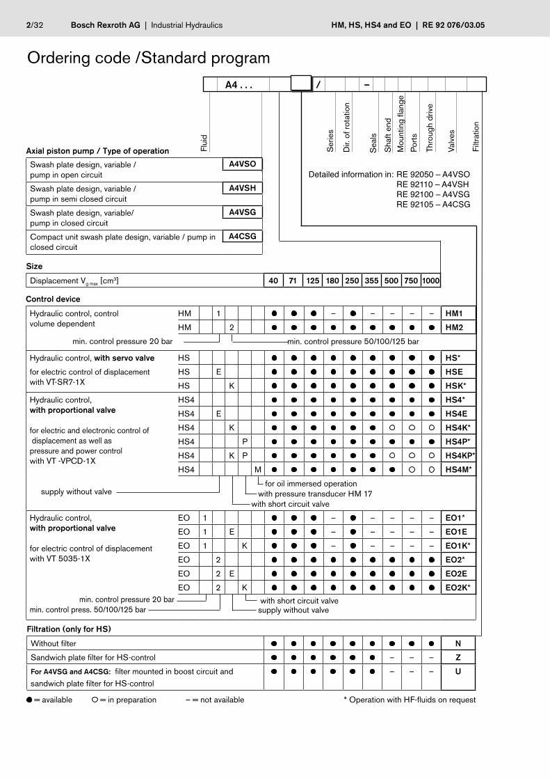
Control device
Hydraulic control, controlvolume dependent
min. control pressure 20 bar
HM 1 – – – – – HM1
HM 2 HM2
min. control pressure 50/100/125 bar
Hydraulic control, with servo valve
for electric control of displacementwith VT-SR7-1X
HS HS*
HS E HSE
HS K HSK*
Hydraulic control, with proportional valve
for electric and electronic control of displacement as well as pressure and power controlwith VT -VPCD-1X
supply without valve
HS4 HS4*
HS4 E HS4E
HS4 K HS4K*
HS4 P HS4P*
HS4 K P HS4KP*
HS4 M HS4M*
for oil immersed operation with pressure transducer HM 17 with short circuit valve
Hydraulic control, with proportional valve
for electric control of displacementwith VT 5035-1X
min. control pressure 20 barmin. control press. 50/100/125 bar
EO 1 – – – – – EO1*
EO 1 E – – – – – EO1E
EO 1 K – – – – – EO1K*
EO 2 EO2*
EO 2 E EO2E
EO 2 K EO2K*
with short circuit valve supply without valve
Ordering code /Standard program
Axial piston pump / Type of operation
Swash plate design, variable /pump in open circuit
A4VSO
Swash plate design, variable / pump in semi closed circuit
A4VSH
Swash plate design, variable/ pump in closed circuit
A4VSG
Compact unit swash plate design, variable / pump in closed circuit
A4CSG
A4 . . . / –
Dir.
of r
otat
ion
Ser
ies
Sha
ft en
d
Sea
ls
Mou
ntin
g fla
nge
Por
ts
Thro
ugh
driv
e
Valv
es
Filtr
atio
n
Flui
d
Detailed information in: RE 92050 – A4VSO RE 92110 – A4VSH RE 92100 – A4VSG RE 92105 – A4CSG
Size
Displacement Vg max [cm3] 40 71 125 180 250 355 500 750 1000
Filtration (only for HS)
Without filter N
Sandwich plate filter for HS-control – – – Z
For A4VSG and A4CSG: filter mounted in boost circuit and sandwich plate filter for HS-control
– – – U
= available = in preparation – = not available * Operation with HF-fluids on request

RE 92 076/03.05 | HM, HS, HS4 and EO Industrial Hydraulics | Bosch Rexroth AG 3/32
15°
0° 1
5°
rechtslinks
K3 K2 R(L)TX1U X2
MB
B
MA
A
EB1 MBBX1X2
K1 K2 R(L)TMSU S
HM1 / HM2 – hydraulic control, control volume dependentThe HM 1/2-control adjusts the pump displacement, dependent on the control oil volume.This control is used for 2-point control systems or as a base unit for controls wit proportional valves (in addition an electric feed-back device is required).The mechanical swivel angle limiting stop screws can be adjusted on both sidesof centre within the range of Vg max down to 50 % Vg max , with the size 500 (HM2) from Vg max to 70% Vg max.
Spring centering of the control cylinder is standard. It is used for settings and adjustments in the unpressurized zero (centre) posi-tion, however without a defined reset during high pressure operation.
2 versions are available:HM1 Min. control pressure 20 bar for sizes 40, 71, 125 and 250HM2 min. control pressure 50/100/125 bar for sizes 40...1000 see page 4
Please note:The Vgmin-stop for the variable displacement pump A4VSO for open circuits is to be adjusted, so that with blocked pressure port B a minimum pressure of appox.. 20 bar is eached.
HM1For pump A4CSG with HM1 control, the necessary control pressure can be taken out of the boost circuit (Port ME3) . Recom-mended setting of the boost pressure relief valve: 25 bar.The control pressure relief valve is not needed, and is replaced by a plug.
Technical dataSize 40 71 125 250
Control press.(in X1, X2) pmin bar 20
pmax bar 100
Control stroke smax mm 14,2 17,1 20,7 25,9
Control area A cm2 16,6 24,6 36,3 56,7
Control volume VS max cm3 23,6 42,1 75,2 147
Weight approx. (A4VSO...HM1...N00) kg 38 55 92 194
Schematic size 125 and 250Example: closed circuit A4VSG
Schematic size 40 and 71Example: open circuit A4VSO
Ports and direction of flow X1 Control pressure port for pressure in B with direction of rotation clockwise, swivel range* left
for pressure in A with direction of rotation ccw., swivel range* left
X2 Control pressure port for pressure in A with direction of rotation clockwise, swivel range* rightfor pressure in B with direction of rotation ccw.., swivel range* right
Example schematic with proportional valve see page17 * compare swivel angle indicatorrightleft

4/32 Bosch Rexroth AG | Industrial Hydraulics HM, HS, HS4 and EO | RE 92 076/03.05
B1 MBBX1X2
K1 K2 R(L)TMSU S
R5R6R7 R2R3R4U X2X1 R(L)K2K3 T
SASB
MB MA
B A
X2
MX2MX1
X1
R5 R6 R7 R2R3R4U R(L)TK2K3
E
MAMB
AB
MX
15°
0° 1
5°
rechtslinks
Technical dataSize 40 71 125 180 250 355 500 750 1000
Control pressure (in X1, X2) pmin bar 50 50 50 100 100 100 125 125 125
pmax bar 350
Control stroke smax mm 14,2 17,1 20,7 20,7 25,9 25,9 32,6 37,0 41,4
Control area A cm2 8,1 12,6 18,1 18,1 28,3 28,3 38,2 56,8 63,6
Control volume VS max cm3 11,4 21,5 37,5 37,5 73,2 73,2 124,5 210 263,3
Weight approx. (A4VSO...HM2...N00) kg 38 55 92 106 194 214 327 470 600
Schematic size 125...355Example: semi closed circuit A4VSH
Schematic size 500...1000Example: closed circuit A4VSG
Schematic size 40 and 71Example: open circuit A4VSO
HM2Pump A4CSG with HM2-control does not need the control pressure relief valve and the cavity is plugged.
In order to minimize the control fluid consumption the control chambers on the sizes 125...1000 are sealed and can be bled through ports R2-R7
Ports and direction of flow X1 Control pressure port for pressure in B with direction of rotation clockwise, swivel range* left
for pressure in A with direction of rotation ccw., swivel range * left
X2 Control pressure port for pressure in A with direction of rotation clockwise, swivel range* rightfor pressure in B with direction of rotation ccw., swivel range* right
MX; MX1; MX2 Gauging ports control pressure (NG 500...1000)
R2-R7 Bleeding ports control chamber (Size 125...1000)
Example schematic with proportional valve see page 17 * compare swivel angle indicatorrightleft

RE 92 076/03.05 | HM, HS, HS4 and EO Industrial Hydraulics | Bosch Rexroth AG 5/32
R(L)
B
R(L)
X1
X2
15°
15°
0LR
A5
A4
A2
A3
A1
Einschraubloch M33
R(L)
B
X1
X2
R(L)
R5
R6
R2
R3
R 4/R7
A4 A
2
A3
A 1
A3
A 5
15°
15°
0LR
Einschraubloch M33
Size 40 und 71
Unit dimensions HM1 / HM2Dimensions valid for A4VSO, A4VSH, A4VSG and A4CSG
Size 125...355
Unit dimensions
Size A1 A2 A3 A4 A5
40 296 136 24 102 217
For detailed dimensions and technical data of the variable pumps see the technical data sheetsA4VSO RE 92050, A4VSH RE 92110, A4VSG RE 92100 or A4CSG RE 92105
71 332 157 28 120 245
125 402 191 67 186,5 251
1801) 402 191 67 186,5 251
250 485 238 71 233 311
3551) 485 238 71 233 3111) only HM2 Dimensions size 500...1000 see page 6 2) see safety information
to mounting flange surface
to mounting flange surface
Mounting flange acc. to DIN 24 340 A6
Before finalising your design please request certified installation drawing
Ports max. tightening torque 2)
X1; X2 Control pressure ports DIN 3852 M14x1,5; 12 deep (Size 40...180) 80 Nm
M18x1,5; 12 deep (Size 250 u. 355) 140 Nm
R2-R7 Bleed port control chamber DIN 3852 M10x1; 8 deep; plugged (Size 125...355) 30 Nm

6/32 Bosch Rexroth AG | Industrial Hydraulics HM, HS, HS4 and EO | RE 92 076/03.05
R(L)
X2
MX1
MX2
X1, X2 MX
B
X1
MX1
A1
A4 A
2
15°
15°
0LR A
3
A5
Einschraubloch M33
RR6
R2
3
R 4/R7
5
R
Unit dimensions HM2Dimensions valid for A4VSO, A4VSG and A4CSG
Unit dimensions
Size A1 A2 A3 A4 A5
500 555 283 50 274 388 For detailed dimensions and technical data of the variable pumps see technical data sheets A4VSO RE 92050, A4VSG RE 92100 oder A4CSG RE 92105
750 630 320 50 304 420
1000 670 347 50 327 4861) see safety information
Ports max. tightening torque 1)
X1; X2 Control pressure port DIN 3852 M27x2; 16 deep 330 NmMX; MX1; MX2 Gauging ports control pressure DIN 3852 M14x1,5; 12 deep; plugged 80 Nm
R2-R7 Bleed ports control chamber DIN 3852 M14x1,5; 12 deep; plugged 80 Nm
to mounting flange surfaceMounting flange acc. to DIN 24 340 A10
Size 500...1000
Before finalising your design pleaserequest certified installation drawing

RE 92 076/03.05 | HM, HS, HS4 and EO Industrial Hydraulics | Bosch Rexroth AG 7/32
15°
0° 1
5°
rechtslinks
HS – displacement control system with servo valvefor electric control of displacement with VT-SR7-1X
The HS- control adjusts the pump displacement with a servo valve proportional to a setpoint value.
The feed back of the actual pump swivel angle (pump displacement) is accomplished with a built on positional transducer. In con-junction with the compatible amplifier VT-SR7-1X we have a very accurate control of pump displacement.
This amplifier VT-SR7-1X does not belong to the supply of the HS-control. Please order separately acc. to RE 29993.
Spring centering in the control cylinder is standard. It is used for settings and adjustments in the unpressurized zero position, however without a defined reset during high pressure operation.
Mechanical swivel angle limiting stops on both sides of centre between Vg max and 50 % Vg max (with size 500 to 70 % Vg max) are standard.
In order to minimize the control fluid consumption the control chambers in the sizes 125...1000 are sealed and can be bled
through the ports R2 - R7 .
In order to protect the servo valve the pump is supplied with a sandwich flushing plate (see schematic) . After the flushing process the flushing plate must be removed and the servo valve must be screwed directly onto the subplate (using the screws supplied). Please observe the commissioning and flushing instructions in RE 07700 and RE 29583.
Optional: HSE without servo valve or HSK with short circuit valve
A4VSO - open circuitPlease note: On the A4VSO pump for open circuit applications (swivel to one side only) the Vgmin-stop is set so that, when port B is plugged a pressure of approx. 20 bar is reached.
Characteristic Direction of flow S to B
Direction of rotation Swivel range*
clockwise left
counter clockwise right
Direction of flow
Direction of rotationclockwise counter clockwise
Swivel range*
B to A A to B right
A to B B to A left
*compare swivel angle indicator
A4VSH - semi closed circuit
Characteristic Direction of flow
Direction of rotationclockwise counter clockwise
Swivel range*
B(SB) to A A(SA) to B right
A(SA) to B B(SB) to A left
A4VSG and A4CSG - semi closed circuitOn pump A4CSG with HS-control the control pressure relief valve is not needed and replaced by a plug.
Characteristic
Vg
Vgmax
UUmax
+UUmax
_ Vg
Vgmax+Vg
Vgmax
–UUmax
+UUmax
_ Vg
Vgmax+
Vg
Vgmax
–UUmax
rightleft

8/32 Bosch Rexroth AG | Industrial Hydraulics HM, HS, HS4 and EO | RE 92 076/03.05
Technical data HSSize 40 71 125 180 250 355 500 750 1000
Control press. in P pmin bar 100 100 100 125 125 125 150 150 150
pmax1) bar 315
Control stroke smax mm 14,2 17,1 20,7 20,7 25,9 25,9 32,6 37,0 41,4
Control area A cm2 8,1 12,6 18,1 18,1 28,3 28,3 38,2 56,8 63,6
Control volume VS max cm3 11,4 21,5 37,5 37,5 73,2 73,2 124,5 210 263,3
Control time tmin2) s 0,04 0,06 0,09 0,09 0,12 0,12 0,15 0,2 *
Weight approx. (A4VSO...HS...N00) kg 42 59 98 112 200 220 333 476 606
Quality of control loop hysteresis ≤ 0,2 %
repeating accuracy ≤ 0,2 %
swivel angle linearity deviation
≤ 1,0 %
1) conditional upon permissible data of servo valve2) at min. control pressure* on request

RE 92 076/03.05 | HM, HS, HS4 and EO Industrial Hydraulics | Bosch Rexroth AG 9/32
U
BB1 MB
R(L)TK2K1
1.1
MSS
SPP
RKV
3
2
6
5
S
MPP
MA2MB2
R5 R6 R7 R2R3R4U R(L)TK2K3
E
MA1MB1
AB
US
AB PT
1.33
2
6
54.2RKV
B SB
MB
R(L)TK2
1.2
M1U
SPP
RKV
3
2
6
5
US
MA
R4 R3R2 M2K1
SA A 4.1
R5 R6 R7
PortsP; SP Control pressure ports
RKV Return line control fluid
MA2; MB2; MP Gauging port control pressure (plugged), size 500...1000
M1; M2 Gauging ports control pressure (plugged), size 125...355
R2 - R7 Bleed port control chamber (plugged), size 125...1000
Components1 Pump with hydraulic control device
1.1 A4VSO (see RE 92050)
1.2 A4VSH (see RE 92110)
1.3 A4VSG (see RE 92100)
2 4/3-way servovalve (see RE 29583)
Size Type
40 and 71 4WS2EM10-5X/20B11ET315K31EV
with cable box to DIN EN 175.201-804for cable diameter 8...13,5mm
125 and 180 4WS2EM10-5X/30B11ET315K31EV
250 and 355 4WS2EM10-5X/45B11ET315K31EV
500...1000 4WS2EM10-5X/75B11ET315K31EV
3 Inductive positional transducer IW9-03-01 with plug to DIN EN 175 301-803-A / ISO 4400 cable connection M16x1,5 cable diameter 4,5...10mm
4.1 Anti cavitation valve (A4VSH)
4.2 boost inlet check valves (A4VSG)
5 Sandwich plate
6 Flushing plate
Schematic size 125...355Example: semi closed circuit A4VSH
Schematic size 500....1000Example: closed circuit A4VSG
Schematic size 40 and 71Example: open circuit A4VSO
Schematics and components HS

10/32 Bosch Rexroth AG | Industrial Hydraulics HM, HS, HS4 and EO | RE 92 076/03.05
M6(x1
)M6
(x1)M 6
( x 1)
M 6(x1
)
M4(x0
.7)
M4(x0
. 7 )
B
R(L)RKV
P
R(L)
P
M1
M2
1
32
6
5
A5
A2
A3
A4
A7
A1A
9 A10
A6
WA
8
15°
15°
0LR
Einschraubloch M33
SPRKV
P
RKV
A11
RR6
R2
3
R 4/R7
5
R
Unit dimensions
Size A1 A2 A3 A4 A5 A6 A7 A8 A9 A10 A11
40 296 269 254 222 108 43 273 128 35 53 246
71 332 287 272 249 123 48 300 143 30 48 263
125 / 180 402 304 289 309 148 39 350 148 0 39 298
250 / 355 485 341 326 371 184 39 412 184 0 39 3451) SP plugged 2) see safety information
For detailed unit dimensions and technical data on the variable pumps see technical data sheets A4VSO RE 92050, A4VSH RE 92110, A4VSG RE 92100 or A4CSG RE 92105
Components see page 9
Ports max. tightening torques 2)
P; Sp Control pressure port DIN 3852 M22x1,5; 14 deep 1) 210 Nm
RKV Return line control fluid DIN 3852 M22x1,5; 14 deep 210 Nm
M1; M2 Gauging port control pressure DIN 3852 M14x1,5; 12 deep; pluggedM18x1,5; 12 tief; plugged
(Size 125 and 180)(Size 250 and 355)
80 Nm140 Nm
R2-R7 Bleed port control chamber DIN 3852 M10x1; 8 deep; plugged (Size 125...355) 30 Nm
Part view W
Size 40...355
Unit dimensions HSDimensions valid for A4VSO, A4VSH, A4VSG and A4CSG
to mounting flange surfaceto mounting flange surface
with
flus
hing
pla
tew
ithou
t flus
hing
pla
te
Before finalising your design pleaserequest certified installation drawing

RE 92 076/03.05 | HM, HS, HS4 and EO Industrial Hydraulics | Bosch Rexroth AG 11/32
0
HS4(P) – hydraulic control system with proportional valvefor electric and electronic displacement as well as pressure and power control with VT-VPCD-1X
Swivel angelactual (αact) Desired
power
= 100 % Actual power
Actual pressureOperating pressure in bar
Sw
ivel
ang
le in
%
The HS4-control adjusts the pump displacement with a directly controlled proportional valve proportional to a setpoint value.
Actual pump swivel angle (displacement) feedback is provided by means of a position transducer. Control HS4P features a built on pressure transducer HM17 which serves to detect and feed back system pressure, pumps A4VSG aund A4CSG have a pres-sure transducer on each pressure side. In conjunction with the compatible control module VT-VPCD and the operating software BODAC the user has at his disposal a highly accurate and free programmable control, which offers a comfortable operating and diagnostics interface.
The digital control amplifier VT-VPCD-1X to drive the HS4-control does not belong to the scope of supply. It must be ordered separately to RE 30028 .
Programming the digital control amplifier VT-VPCD is executed via the amplifier‘s serial interface with the PC-program BODAC. For more information see RE 30028.
Optional: HS4P with pressure transducer for additional pressure and power control HS4E without proportional valve HS4K, HS4KP with short circuit valve HS4M for operation under oil level
Stop screws to limit the swivel angle between Vg max and 50 % Vg max (for size 500 to 70 % Vg max) for both side of centre are stan-dard.
Spring centering in the control cylinder is standard. It is used for settings and adjustments in the unpressurized zero position, however without a defined reset during high pressure operation.
In order to minimize the control fluid consumption the control chambers in pump sizes 125...1000 are sealed and can be bled via ports R2 - R7 .
A4VSO – open circuitWhen the valve is de-energized and the control pressure is on the pump swivels towards Vg min.The Vg min-stop set so that, when port B is plugged, a pressure of approx. 20 bar is reached.
A4VSH, A4VSG, A4CSG – closed and semi closed circuitFor controls of these pumps without short circuit valve it must be noted, that, when the valve is de-energized and the control pressure is on the pump will stroke towards Vg max (swivel angle range to the right).On pumps A4CSG with HS4-control the control pressure relief valve is not needed and replaced by a plug.

12/32 Bosch Rexroth AG | Industrial Hydraulics HM, HS, HS4 and EO | RE 92 076/03.05
Technical data HS4(P)Size 40 71 125 180 250 355 500 750 1000
Control press. in P pmin bar 100 100 100 125 125 125 150 150 150
pmax1) bar 315
Control stroke smax mm 14,2 17,1 20,7 20,7 25,9 25,9 32,6 37,0 41,4
Control area A cm2 8,1 12,6 19,0 19,0 28,3 28,3 38,2 56,8 63,6
Control volume VS max cm3 11,4 21,5 37,5 37,5 73,2 73,2 124,5 210 263,3
Control time tmin2) s 0,04 0,06 0,09 0,09 0,12 0,12 0,15 0,2 0,25
Weight approx. (A4VSO...HS4...N00) kg 42 59 98 112 200 220 333 476 606
Quality of control loop
hysteresis ≤ 0,2 %
repeating accuracy ≤ 0,2 %
swivel angle linearity deviation
≤ 1,0 %
pressure linearity deviation ≤ 1,5 % of pmax3)
1) limited by the permissible proportional valve data2) at min. control pressure3) Pressure transducer value
RE 92 076/03.05 | HM, HS, HS4 and EO Industrial Hydraulics | Bosch Rexroth AG 13/32
U
BB1 MB
R(L)TK2K1
1.1
MSS R6R5 R7 M2R3R4 R2M1U
SPP
RKV
3
2
5
S
(6)
PI
ab
ab
PT
AB
ab
U
B
MB1
MB2
R(L)TK2K3
1.2
R6R5 R7 R3R4 R2U
MP
MA2
PRKV
3
2
5
S
ab
ab
PT
AB
4
A
E
MA1
U
BB1 MB
R(L)TK2K1
1.1
MSS R6R5 R7 M2R3R4 R2M1U
SPP
RKV
3
2
5
S
(6)
PI
ab
ab
PT
AB
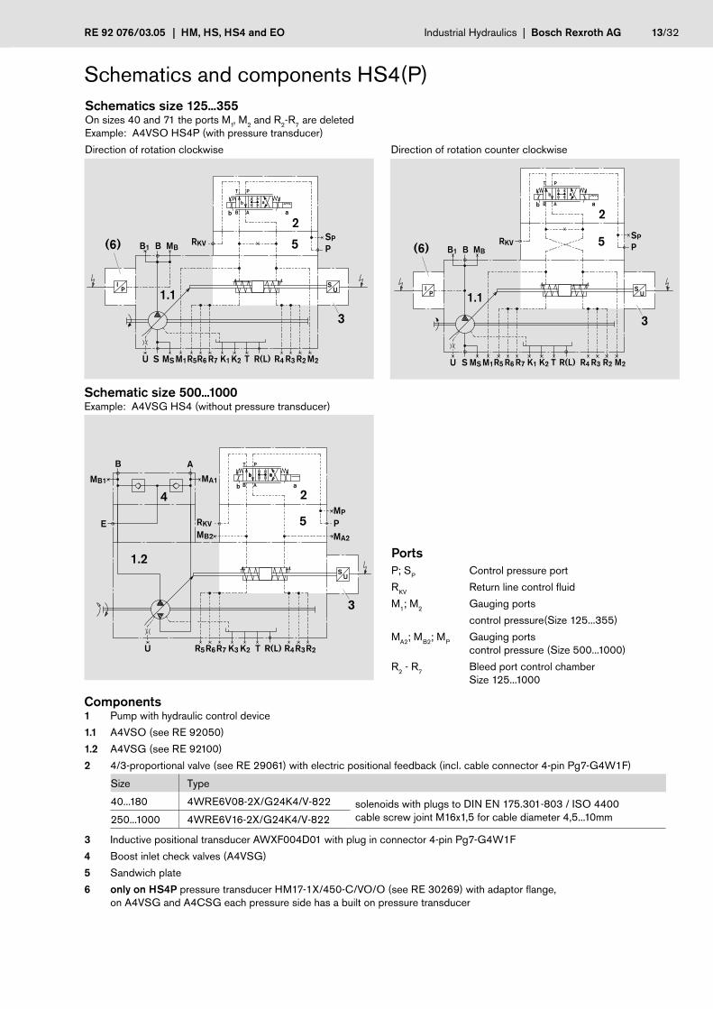
Schematic size 500...1000Example: A4VSG HS4 (without pressure transducer)
Schematics size 125...355 On sizes 40 and 71 the ports M1, M2 and R2-R7 are deletedExample: A4VSO HS4P (with pressure transducer)
Direction of rotation clockwise Direction of rotation counter clockwise
Schematics and components HS4(P)
PortsP; SP Control pressure port
RKV Return line control fluid
M1; M2 Gauging ports
control pressure(Size 125...355)
MA2; MB2; MP Gauging ports control pressure (Size 500...1000)
R2 - R7 Bleed port control chamber Size 125...1000
Components1 Pump with hydraulic control device
1.1 A4VSO (see RE 92050)
1.2 A4VSG (see RE 92100)
2 4/3-proportional valve (see RE 29061) with electric positional feedback (incl. cable connector 4-pin Pg7-G4W1F)
Size Type
40...180 4WRE6V08-2X/G24K4/V-822 solenoids with plugs to DIN EN 175.301-803 / ISO 4400cable screw joint M16x1,5 for cable diameter 4,5...10mm250...1000 4WRE6V16-2X/G24K4/V-822
3 Inductive positional transducer AWXF004D01 with plug in connector 4-pin Pg7-G4W1F
4 Boost inlet check valves (A4VSG)
5 Sandwich plate
6 only on HS4P pressure transducer HM17-1X/450-C/VO/O (see RE 30269) with adaptor flange, on A4VSG and A4CSG each pressure side has a built on pressure transducer

14/32 Bosch Rexroth AG | Industrial Hydraulics HM, HS, HS4 and EO | RE 92 076/03.05
SPRKV
P
A1
A2
A2
A5 A
8
A3
A 4
A7
W
23
1
P(SP)
RKV
(6)
5
A9 A10
A6
30
----
Schl.weite: 36 mm
Schl.weite: 36 mm
Schl.weite: 13 mm
M5 (x0.8)
--a40
--
B
R(L)
15°15
°0LR
Einschraubloch M33
M12 (x1.75)
Unit dimensions HS4(P)On A4VSO for direction of rotation clockwise and ccw. some dimensions are different. For A4VSH, A4VSG and A4CSG the dimensions under„right“ are valid for both directions of rotation
Sizes 40 and 71 Example A4VSO HS4P with a pressure transducer in port B
Unit dimensions
Size A1 A2 left A2 right A3 left A3 right A4 right A4 left A5 A6 A7 right A7 left A8 right A8 left A9 right A9 left A10
40 296 166 174 226 245 222 229,5 108 43 273 253 128 94 35 5 54
71 332 171 169 241 261 249 256,5 123 48 300 280 143 109 30 0 49
Dimensions size 125...1000 see page 15 and 16 1) SP plugged 2) see safety instructions
For detailed unit dimensions and technical data of the variable pumps see technical data sheets of A4VSO RE 92050, A4VSH RE 92110, A4VSG RE 92100 oder A4CSG RE 92105
Components see page 13
Ports max. tightening torque 2)
P; Sp Control pressure ports DIN 3852 M22x1,5; 14 deep 1) 210 Nm
RKV Return line control fluid DIN 3852 M22x1,5; 14 deep 210 Nm
to mounting flange surfaceto mounting flange surface
Valve position on A4VSH, A4VSG, A4CSG and A4VSO direction of rotation clockwise
Part view W
Before finalising your design pleaserequest certified installation drawing
Valve position on A4VSO direction of rotation counter clockwise
with press. transducer item 6:Adapter flange with 30 mm through holes for fixing screws(For thread of fixing screws see relevant data sheets of pumps) Transport protection

RE 92 076/03.05 | HM, HS, HS4 and EO Industrial Hydraulics | Bosch Rexroth AG 15/32
B
R(L)
M1
M2
A
RKV
P
A8 A
5
A3
A6
A6
SP RKV
P
5
R6
R2R3
R 4/R7
R
30
(6)
A4
A7
--a40
--
Einschraubloch M22
M10 (x1.5)
----
f
Schl.weite: 13 mm
A1
1
32
5
EinschraublochM22
W
15°
15°
0LR
Einschraubloch M33
M14 (x2)
Unit dimensions
Size A1 A3 A4 right A4 left A5 A6 A7 A8
125 / 180 402 280 310 318,5 156 39 350 148
250 / 355 485 316 372 380,5 192 39 412 184
Dimensions sizes 40 and 71 see page 14 1) SP plugged 2) see safety information
For detailed unit dimensions and technical data of the variable pumps see the technical data sheets of the pumps A4VSO RE 92050, A4VSH RE 92110, A4VSG RE 92100 oder A4CSG RE 92105
Components see page 13
Ports max. tightening torque 2)
P; Sp Control pressure ports DIN 3852 M22x1,5; 14 deep 1) 210 Nm
RKV Return line control fluid DIN 3852 M22x1,5; 14 deep 210 Nm
M1; M2 Gauging ports control pres-sure
DIN 3852 M14x1,5; 12 deep; pluggedM18x1,5; 12 tief; verschlossen
(Size 125 a. 180)(Size 250 a. 355)
80 Nm140 Nm
R2-R7 Bleed port control chamber DIN 3852 M10x1; 8 deep; plugged 30 Nm
Valve position on A4VSO direction of rotation counter clockwise
to mounting flange surfaceto mounting flange surface
Part view W
Unit dimensions HS4(P) With A4VSO the dimension A4 is different for clockwise and counter clockwise direction of rotation. With A4VSH, A4VSG and A4CSG the dimension A4 right is valid for both directions of rotation.
Size 125...355 Example A4VSG HS4P with a pressure transducer in each of the ports A and B
Before finalising your design please request certified installation drawing
Transport protection
with pressure transducer item 6:Adapter flange with 30 mm through holes for fixing screws (For thread of fixing screws see the relevant data sheet of the pump)
Valve position on A4VSH, A4VSG, A4CSG and A4VSO direction of rotation clockwise

16/32 Bosch Rexroth AG | Industrial Hydraulics HM, HS, HS4 and EO | RE 92 076/03.05
0243
7369
0098
8104
02422845
0243
7369
MP MB2
B
(6)
M12 (x1.75)
15°
15°
0L
Einschraubloch M33
P
Rkv
A6
A2
A4
A 5
A3
A1
R(L)
R
0243
7369
MA
/R4
R2R3
R5R6
R7
30
53
1
2
Unit dimensions
Size A1 A2 A3 A4 A5 A6
500 555 361 392 274 388 50 For detailed unit dimensions and technical data of the variable pumps see the technical data sheets of A4VSO RE 92050, A4VSG RE 92100 oder A4CSG RE 92105
750 630 400 424 304 420 50
1000 670 427 490 327 486 50
Dimensions size 40...355 see page 14 and 15 1) see safety information
Conponents see page 13
Ports max. tightening torque 1)
P Control pressure port DIN 3852 M27x2; 16 deep 330 NmRKV Return line control fluid DIN 3852 M27x2; 16 deep 330 NmMA2; MB2; MP Gauging ports control pressure DIN 3852 M14x1,5; 12 deep; plugged 80 NmR2 - R7 Bleed port control chamber DIN 3852 M14x1,5; 12 deep; plugged 80 Nm
to mounting flange surface
to mounting flange surface
Unit dimensions HS4(P) Dimensions valid for A4VSO, A4VSG and A4CSG
Size 500...1000 Example HS4P with a pressure transducer in port B
Before finalising your design please request certified installation drawing
Valve position on A4VSO direction of rotation ccw.
Valve position on A4VSG, A4CSG and A4VSO direction of rotation clockwise
Transport protection
with pressure transducer item 6:Adapter flange with 30 mm through holes for fixing screws (For thread of fixing screws see relevant data sheet of the pump)

RE 92 076/03.05 | HM, HS, HS4 and EO Industrial Hydraulics | Bosch Rexroth AG 17/32
15°
0° 1
5°
rechtslinks
ab
ab
PT
X2X1
US
R5 R6 R7 R2R3R4U
BB1 MB
R(L)TK2K1MSS
ABab
ab
PT
AB
X2X1
US
R5 R6 R7 R2R3R4U
BB1 MB
R(L)TK2K1MSS
HS4M – for oil immersed (under oil level) operation Control option HS4M corresponds to the HS4 version however without proportional valve, but with control pressure ports X1 and X2.The proportional valve can be mounted separately into the system and be connected to the relevant ports X1 and X2 of the pump. The pump unit together with the attached positional transducer can be mounted inside the reservoir.
Recommended: proportional valve 4WRE6-2X see RE 29061 electronic control VT-VPCD-1X see RE 30028 cable see RE 30028-B
Please note:
On the A4VSO pumps for open circuit applications (swivel to one side only) the Vgmin-stop is set so that, when port B is plugged, a pressure of approx. 20 bar is reached.
On A4CSG with HS4M the control pressure relief valve is not needed and replaced by a plug.
Schematic example open circuit A4VSO size 125...500
Direction of rotation clockwise Direction of rotation counter clockwise
Ports and direction of flow X1 Control pressure port for pressure in B with direction of rotation clockwise, swivel range* left
for pressure in A with direction of rotation ccw., swivel range left* links
X2 Control pressure port for pressure in A with direction of rotation clockwise, swivel range* rightfor pressure in B with direction of rotation ccw., swivel range* right
R2-R7 Bleed port control chamber (Size 125...1000) * compare swivel angle indicator
Technical data HS4MSize 40 71 125 180 250 355 500 750 1000
Control pressure (in X1, X2) pmin bar 50 50 50 100 100 100 125 125 125
pmax bar 350
Control stroke smax mm 14,2 17,1 20,7 20,7 25,9 25,9 32,6 37,0 41,4
Control area A cm2 8,1 12,6 18,1 18,1 28,3 28,3 38,2 56,8 63,6
Control volume VS max cm3 11,4 21,5 37,5 37,5 73,2 73,2 124,5 210 263,3
Weight approx. (A4VSO...HS4M..N00)kg 38 55 92 106 194 214 327 470 600
Induktiv positional transducer AWXF004D01with 4-pin plug in connector Pg7-G4W1F
is not part of the supply of the HS4M
rightleft

18/32 Bosch Rexroth AG | Industrial Hydraulics HM, HS, HS4 and EO | RE 92 076/03.05
B
R(L)
X1
X2
15°
15°
0LR
A4
A2
A3
A1
Einschraubloch M33
A 5
B
X1
X2
A4 A
2
A3
A 1
A3
A 515
°15
°0LR
Einschraubloch M33
R(L)
Unit dimensions
Size A1 A2 A3 A4 A5
40 296 221,5 24 102 217 For detailed unit dimensions and technical data of the variable pumps see the technical data sheets of A4VSO RE 92050, A4VSH RE 92110, A4VSG RE 92100 or A4CSG RE 92105
71 332 243 28 120 245
125/180 402 273 67 186,5 251
250/355 485 309 71 233 311
500 555 361 224 205 399
Sizes 750 and 1000 on request 2) see safety information
Ports max. tightening torque 2)
X1; X2 Control pressure ports DIN 3852 M14x1,5; 12 deep (Size 40...180) 80 Nm
M18x1,5; 12 deep (Size 250 a. 355) 140 Nm
M22x1,5; 14 deep (Size 500) 210 Nm
to mounting flange surface to mounting flange surface
Unit dimensions HS4MDimensions valid for A4VSO, A4VSH, A4VSG and A4CSG
Sizes 40, 71 and 500 Sizes 125...355
Before finalising your design pleaserequest certified installation drawing
Inductive positional trans-ducer size 40

RE 92 076/03.05 | HM, HS, HS4 and EO Industrial Hydraulics | Bosch Rexroth AG 19/32
15°
0° 1
5°
rechtslinks
EO1 / EO2 – hydraulic control system with proportional valvefor electric control of displacement with VT 5035-1X
The EO1/2 control adjusts the pump displacement proportional to a command input value, by means of a built on directly driven proportional directional valve.
The feedback signal for the actual pump swivel angle (displacement ) is provided by a positional transducer.
The max. swivel angle can be adjusted on both sides of centre with stop screws between Vg max and 50 % Vg max for the pump size 500 (EO2) from Vg max to 70 % Vg max.
Spring centering of the control cylinder is standard. It is used for settings and adjustments in the unpressurized zero posi-tion, however without a defined reset during high pressure operation.
The electric amplifier VT 5035-1X to control the pump displacement does not belong to the supply of the EO , it must be orde-red separately acc. to RE 29955 .
2 versions are available:EO1 min. control pressure 20 bar for pump sizes 40...250 see page 20...22EO2 min. control pressure 50/100/125 bar for pump sizes 40...1000 see page 23...26
A4VSO - open circuitPlease note: On the A4VSO pump for open circuit applications (swivel to one side only) the Vgmin-stop is set so that, when port B is plugged a pressure of approx. 20 bar is reached.
Characteristic Direction of flow S to B
Direction of rot. Swivel range* / or solenoid energized
Clockwise left / a
Counterclockwise right / b
Direction of flow
Swivel range* /or solenoid energized
Direction of rot.clockwise c. clockwise
right / b B to A A to B
left / a A to B B to A
* compare swivel angle indicator
A4VSH - semi closed circuitCharacteristic Direction of flow
Swivel range* /or solenoid energized
Direction of rot.clockwise c. clockwise
right / b B(SB) to A A(SA) to B
left / a A(SA) to B B(SB) to A
A4VSG and A4CSG - closed circuitCharacteristic
Vg
Vgmax
UUmax
+UUmax
_ Vg
Vgmax+Vg
Vgmax
–UUmax
+UUmax
_ Vg
Vgmax+
Vg
Vgmax
–UUmax
rightleft

20/32 Bosch Rexroth AG | Industrial Hydraulics HM, HS, HS4 and EO | RE 92 076/03.05
Size 40 71 125 250
Control pressure in P pmin bar 20
pmax bar 100
Control stroke smax mm 14,2 17,1 20,7 25,9
Control area A cm2 16,6 24,6 36,3 56,7
Control volume VS max cm3 23,6 42,1 75,2 147
Control time tmin1) s 0,12 0,20 0,22 0,40
Weight approx. (A4VSO...EO1..N00) kg 42 59 98 200
max. hysteresis ∆ Vg 2) ≤ ± 2 % von Vg max
min. repeating accuracy 2) ≤ ± 1,5 % von Vg max
Linearity deviation 2) ≤ 2,5 % von Vg max
1) at 50 bar control pressure2) Values valid for constant operating temperatue of 50 °C
Technical data EO1

RE 92 076/03.05 | HM, HS, HS4 and EO Industrial Hydraulics | Bosch Rexroth AG 21/32
Us
ab
K2 K3 R(L)TU P
MB
B
MA
A
E
2
3
4
1.1
U
a
s
b
K1 K2MS M1 R(L)TU S M2
B RKVPB1
2
31.2
MBSP5
PortsP; SP Control pressure porte (SP only on sizes 125 and 250)
RKV Return line control fluid (sizes 125 and 250)
M1; M2 Gauging ports control pressure (sizes 125 and 250)
Components1 Pump with hydraulic control device
1.1 A4VSG (see RE 92100)
1.2 A4VSO (see RE 92050)
2 4/3-way proportional valve
Size Type
40 and 71 4WRA6V15-2X/G24N9Z4/V-589 with plug in connector to DIN EN 175 301-803 / ISO 4400Cable joint M16x1,5 for cable diameter 4,5..10mm125 u. 250 4WRA6V30-2X/G24N9Z4/V-589
3 Induktiv positional transducer IW9-03-01 with plug in connector to DIN EN 175 301-803-A / ISO 4400 cable joint M16x1,5 for cable diameter 4,5...10mm
4 Boost inlet check valves (A4VSG)
5 Throttle plate
Schematic sizes 125 and 250Example: open circuit A4VSO
Schematic sizes 40 and 71Example: closed circuit A4VSG
Schematics and components EO1 The control fluid, externally supplied through port P leaves the pump through the case drain ports R(L) .
For pump type A4CSG with EO1- control, the control is fed from the boost circuit (port ME3) , that means port P is piped already . Recommended setting of boost pressure relief valve: 25 bar.

22/32 Bosch Rexroth AG | Industrial Hydraulics HM, HS, HS4 and EO | RE 92 076/03.05
P
B
2
3
1.1
R(L)
P
15°
15°
0LR
Einschraubloch M33
A2
A3
A1
A4
A5
A7 A
5
A2
A6
A6
A1
A8
15°
15°
0LR
Einschraubloch M33
A 4
P
RKVSP
M1
M2
R(L)
1.1
3 2
5
B
P(SP)
RKV
R(L)
5
R6
R2R3
R 4/R7
R
Unit dimensions
Size A1 A2 A3 A4 A5 A6 A7 A8
40 296 246 279 178 135 – – – For detailed unit dimensions and technical data of the variable pumps see the techni-cal data sheets for the A4VSO RE 92050, A4VSH RE 92110, A4VSG RE 92100 or A4CSG RE 92105
71 332 265 306 205 152 – – –
125 402 298 – 312 156 39 148 352
250 485 345 – 372 192 39 184 4121) plugged 2) see safety information
Components see page 21
Ports max. tightening torques 2)
P Control pressure port DIN 3852 M14x1,5; 12 deepM22x1,5; 14 deep
(Size 40 and 71)(Size 125 and 250)
80 Nm210 Nm
SP Control pressure port DIN 3852 M22x1,5; 14 deep 1) (Size 125 and 250) 210 Nm
RKV Return line control fluid DIN 3852 M22x1,5; 14 deep 1) (Size 125 and 250) 210 Nm
M1; M2 Gauging ports control press. DIN 3852 M18x1,5; 12 deep 1) (Size125 and 250) 140 Nm
R2-R7 Bleed port control chamber DIN 3852 M10x1; 8 deep; plugged (Size 125...355) 10 Nm
to mounting flange surface
to mounting flange surfaceto mounting flange surface
to mounting flange surface
Unit dimensions EO1Dimensions valid for A4VSO, A4VSH, A4VSG and A4CSG
Sizes 40 and 71 Sizes 125 and 250
Befor finalising your design please request certified installation drawing
RE 92 076/03.05 | HM, HS, HS4 and EO Industrial Hydraulics | Bosch Rexroth AG 23/32
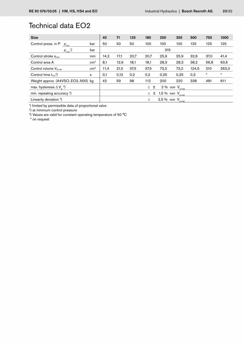
Technical data EO2Size 40 71 125 180 250 355 500 750 1000
Control press. in P pmin bar 50 50 50 100 100 100 125 125 125
pmax1) bar 315
Control stroke smax mm 14,2 17,1 20,7 20,7 25,9 25,9 32,6 37,0 41,4
Control area A cm2 8,1 12,6 18,1 18,1 28,3 28,3 38,2 56,8 63,6
Control volume VS max cm3 11,4 21,5 37,5 37,5 73,2 73,2 124,5 210 263,3
Control time tmin2) s 0,1 0,12 0,2 0,2 0,25 0,25 0,3 * *
Weight approx. (A4VSO..EO2..N00) kg 42 59 98 112 200 220 338 481 611
max. hysteresis ∆ Vg 3) ≤ ± 2 % von Vg max
min. repeating accuracy 3) ≤ ± 1,5 % von Vg max
Linearity deviation 3) ≤ 2,5 % von Vg max
1) limited by permissible data of proportional valve2) at minimum control pressure3) Values are valid for constant operating temperature of 50 °C * on request

24/32 Bosch Rexroth AG | Industrial Hydraulics HM, HS, HS4 and EO | RE 92 076/03.05
ab
SPP
RKV
US
U
BB1 MB
R(L)TK2K1MSS
2
31.1
5
2
31.1
5
ab
SPP
RKV
US
R5R6R7 R2R3R4U M2M1
BB1 MB
R(L)TK2K1MSS
MA1MB1
B A
E
ab
MA3MB3
R5R6 R7 R2R3R4U R(L)TK3K2
US
RKV MPPMA2
MB2
2
31.2
6
5
4
Schematic sizes 125...355Example: open circuit A4VSO
Schematic sizes 500...1000Example: closed circuit A4VSG
Schematic sizes 40 and 71Example: open circuit A4VSO
Ports P; SP Control pressure ports
RKV Return line control fluid
M1; M2 Gauging ports control press. (Size 125...355)
MA2; MB2; MP; MA3; MB3 Gauging ports control press. (Size 500...1000)
R2-R7 Bleed port control chamber (Size 125...1000)
Components1 Pump with hydraulic control device
1.1 A4VSO (see RE 92050)
1.2 A4VSG (see RE 92100)
2 4/3-way proportional valve
Size Type
40 and71 4WRA6V15-2X/G24N9Z4/V-589with plug in connector to DIN EN 175 301-803 / ISO 4400cable joint M16x1,5 for cable diameter 4,5..10mm
125...355 4WRA6V30-2X/G24N9Z4/V-589
500...1000 4WRE10E25-2X/24Z4/V-93
3 Induktiv positional transducer IW9-03-01 with plug in connector DIN EN 175 301-803 / ISO 4400 cable joint M16x1,5 for cable diameter 4,5...10mm
4 Boost inlet check valves (A4VSG)
5 Sandwich plate
6 Throttle plate (Size 500...1000)
Schematics and components EO2 The control fluid, externally supplied through port P leaves the housing through the case drain ports R(L) on pumps up to incl.
size 355 . As of the size 500 the port RKV must be connected to tank to drain this control fluid.
On pump type A4CSG with EO2-control the control pressure relief valve is not needed and replaced by a plug.
In order to minimize the control fluid consumption the control chambers on the sizes 125...1000 are sealed and can be bled via ports R2 - R7 .

RE 92 076/03.05 | HM, HS, HS4 and EO Industrial Hydraulics | Bosch Rexroth AG 25/32
R(L)
P
RKV
B
RKV
P
1.1
3
2
5
M1
M2
5
R6
R2R3
R 4/R7
R
15°
15°
0LR
Einschraubloch M33
A3
A2
A5 A
8
A7A4
A1
A6
A9A9 A10
A6
W
SPRKV
P
to mounting flange surfaceto mounting flange surface
Part view W
Unit dimensions
Size A1 A2 A3 A4 A5 A6 A7 A8 A9 A10
40 296 248 246 222 108 43 273 128 35 53 For detailed dimensions and technical data of the variable pumps see the technical data sheets for the A4VSO RE 92050, A4VSH RE 92110, A4VSG RE 92100 or A4CSG RE 92105
71 332 264 265 249 123 48 300 143 30 48
125/180 402 281 298 310 156 39 350 148 0 39
250/355 485 317 345 372 192 39 412 184 0 39
Dimensions size 500...1000 see page 26 2) see safety information
Components see page 24
Ports max. tightening torque 2)
P; SP Control pressure ports DIN 3852 M22x1,5; 14 deep; SP plugged 210 Nm
RKV Return line control fluid DIN 3852 M22x1,5; 14 deep; plugged 210 Nm
M1; M2 Gauging ports control pressure
DIN 3852 M14x1,5; 12 deep; pluggedM18x1,5; 12 deep; plugged
(Size 125 a. 180)(Size 250 a. 355)
80 Nm140 Nm
R2-R7 Bleed port control chamber DIN 3852 M10x1; 8 deep; plugged (Size 125...355) 10 Nm
Unit dimensions EO2Dimensions valid for A4VSO, A4VSH, A4VSG and A4CSG
Sizes 40...355
Before finalising your design pleaserequest certified installation drawing

26/32 Bosch Rexroth AG | Industrial Hydraulics HM, HS, HS4 and EO | RE 92 076/03.05
A5
R(L)
PRKV
P, RKV
A2
/R4
A3
A4
B
R2R3
R5R6
A6
A1
MP
MB3
MB2
MA2
MA3
1
3
25
6
R7
15°
15°
0LR
Einschraubloch M33
Unit dimensions
Size A1 A2 A3 A4 A5 A6
500 555 559 392 274 388 50 For detailed unit dimensions and technical data of the variable pumps see the technical data sheets for the A4VSO RE 92050, A4VSG RE 92100 or A4CSG RE 92105
750 630 591 427 304 420 50
1000 670 657 456 327 486 50
Dimensions size 40...355 see page 25 2) see safety information
Components see page 24
Ports max. tightening torques 2)
P Control pressure ports DIN 3852 M27x2; 16 deep 330 Nm
RKV Return line control fluid DIN 3852 M27x2; 16 deep 330 Nm
MP; MA2; MB2 Gauging ports control pressure DIN 3852 M14x1,5; 12 deep; plugged 80 Nm
MA3; MB3 Gauging ports control pressure DIN 3852 G 1/4; plugged 70 Nm
R2– R7 Bleed port control chamber DIN 3852 M14x1,5; 12 deep; plugged 80 Nm
to mounting flange surface
to mounting flange surface
Unit dimensions EO2Dimensions valid for A4VSO, A4VSG and A4CSG
Sizes 500...1000
Before finalising your design pleaserequest certified installation drawing

RE 92 076/03.05 | HM, HS, HS4 and EO Industrial Hydraulics | Bosch Rexroth AG 27/32
U
BB1 MB
R(L)TK2K1R2R3R4
1
MSSU
SPP
RKV
3
6
5
S
R7R6R5
Version E without valveThis version is being supplied without the control valve.
Apart from that, this version corresponds to the respective basic execution – technical data, respective schematics and unit dimensions see basic control version.
HSEExecution witout servo valve
The mounting pad for the servo valve corresponds to porting pattern DIN 24340-A10 .
SchematicExample size 125...355
HS4E / EO1E / EO2EExecution without proportional valve
For pump sizes 40 up to incl. 355 the mounting pad on the EO1E and EO2E corresponds to DIN 24340-A6 and for the sizes 500...1000 to DIN 24340-A10 .
For the HS4E-control the porting pattern corresponds to
DIN 24340-A6 on all sizes.
Components1 Pump with hydraulic control device
3 Induktiv positional transducer
Type IW9-03-01 (EO1/2E, HSE) Type AWXF (HS4E)
5 Sandwich plate
6 Flushing plate (only HSE)

28/32 Bosch Rexroth AG | Industrial Hydraulics HM, HS, HS4 and EO | RE 92 076/03.05
ab
SPP
RKV
US
R5R6R7 R2R3R4U M2M1
BB1 MB
R(L)TK2K1MSS
A 4
RKV
R(L)
P
B
A2
50
A3
U
BB1 MB
R(L)TK2K1R2R3R4
1
MSSU
SPP
RKV
3
6
5
S
R7R6R5
K – short circuit valve HSKA solenoid actuated 4/2-way shut-off valve is mounted between the servo valve and the control device.
This short circuit arrangement is used for settings and adjustments in the unpressurized zero position, however without a defined reset during high pressure operation – it is not an emergency shut-down function.
Short circuit valve (4/2-way shut off valve) Type Z4WEH10E68-4X/6EG24N9ETZ4/B10D3 (see RE 24753) with plug in connector DIN EN 175301-803-Acable joint M16x1,5 for cable diameter 4,5...10 mm
SchematicExample: A4VSO size 125...355on sizes 40 and 71 ports R2–R7 deleted
Unit dimensions
Size 40 71 125 180 250 355
A2 318 336 355 355 390 390
A3 303 321 340 340 375 375
A4 403 430 479 479 541 541
with
flus
hing
pla
tew
ithou
t flus
hing
pla
te
to mounting flange surface
Unit dimensions Sizes 40...355
Before finalising your design pleaserequest certified installation drawing
HS4K / EO1K / EO2K size 40...355 see page 29
EO2K size 500...1000 see page 30

RE 92 076/03.05 | HM, HS, HS4 and EO Industrial Hydraulics | Bosch Rexroth AG 29/32
ab
SPP
RKV
US
R5R6R7 R2R3R4U M2M1
BB1 MB
R(L)TK2K1MSS
A2
A 3
50
P
M12 (x1.75)
--a40
--
B
--a40
A7
B
P
A5A
6
50
A4
P
R(L)
50
SchematicExample A4VSO EO2K sizes 125...355
Unit dimensions
Size A2 A3 A4 A5 A6 A7
40 295 296 324 298 246 295
71 311 323 351 314 265 322
125 330 381 – 331 298 379
180 330 381 – 331 298 379
250 365,5 443 – 365 345 443
355 365,5 443 – 365 345 443
EO2K sizes 500...1000 see page 30
Short circuit valve (4/2-way shut off valve)Type Z4WE6E68-3X/EG24N9Z4/V (see RE 23193)
with plug in connector DIN EN 175 301-803-Acable joint M16x1,5for cable diameter 4,5...10 mm
Please observe performance limits to RE 23193 .
K – short circuit valve HS4K / EO1K / EO2K Sizes 40...355A solenoid actuated 4/2-way shut off valve is mounted between the proportional valve and the control device.This short circuit arrangement is used for settings and adjustments in the unpressurized zero position, however without a defined reset during high pressure operation – this is not an emergency shut-down function.
Unit dimensionsHS4K Sizes 40...355
EO1K sizes 125 und 250EO2K sizes 40...355
to mounting flange surface
to mounting flange surface
EO1K sizes 40 and 71
to mounting flange surface
Before finalising your design pleaserequest certified installation drawing

30/32 Bosch Rexroth AG | Industrial Hydraulics HM, HS, HS4 and EO | RE 92 076/03.05
MA1MB1
B A
E
ab
MA3MB3
R5R6 R7 R2R3R4U R(L)TK3K2
US
RKV MPPMA2
MB2
ab
A2A
3
50
A4
B
P
U
BB1 MB
R(L)TK2K1R2R3R4
1
MSSU
SPP
RKV
3
6
5
S
R7R6R5
K – short circuit valveEO2K sizes 500...1000A solenoid actuated 4/2-way shut off valve is mounted between the proportional valve and the control device.
This short circuit arrangement is used for settings and adjustments in the unpressurized zero position, however without a defined reset during high pressure operation – this is not an emergency shut-down function.
Unit dimensions
Size 500 750 1000
A2 386 417 439
A3 392 427 456
A4 609 641 707
Short circuit valve (4/2-way shut off valve)Type Z4WEH10E68-4X/6EG24N9ETZ4/B10D3 (see RE 24753) with plug in connector DIN EN 175301-803-Acable joint M16x1,5for cable diameter 4,5...10 mm
SchematicExample: A4VSG
Unit dimensions
to mounting flange surface
EO2K sizes 40...355 see page 29
Before finalising your design pleaserequest certified installation drawing

RE 92 076/03.05 | HM, HS, HS4 and EO Industrial Hydraulics | Bosch Rexroth AG 31/32
��
�����
��RKV
R4R3R2R7R6R5U
BB1 MB
R(L)TK2K1S ������
�B
RKV
P A2
A3
A 4
R(L)
A1
Z – sandwich plate filterthe digit for the filtration option in the model code
This sandwich plate filter is used to filter the control fluid before entering the servo valve in the HS-control. It is denoted with the letter Z in the pump model code.
HS4 with sandwich plate filter on request.
Schematic
Unit dimensions HS...Z Sizes 40...355
Sandwich plate filterContamination indicator is optical and electrical– indicator lamp voltage 24V
Size Type
40 and 71 DFBH/HC60Z10D2.0/V-L24
125...355 DFBH/HC110Z10D2.0/V-L24
Unit dimensions
Size A1 A2 A3 A4
40 216 342 327 300
71 212 350 335 312
125/180 272 374 359 376
250/355 272 411 396 438to mounting flange surface
Before finalising your design please request certified installation drawing
with
flus
hing
pla
tew
ithou
t flus
hing
pla
te

32/32 Bosch Rexroth AG | Industrial Hydraulics HM, HS, HS4 and EO | RE 92 076/03.05
© This document, as well as the data, specifications and other informations set forth in it, are the exclusive property of Bosch Rexroth AG. Without their consent it may not be reproduced or given to third parties.
The data specified above only serve to describe the product. No statements con-cerning a certain condition or suitability for a certain application can be derived from our information. The given information does not release the user from the obligation of own judgement and verification. It must be remembered that our products are subject to a natural process of wear and aging.
Subject to change.
Bosch Rexroth AG Mobile HydraulicsProduct Segment Axial Piston UnitsPlant Horb An den Kelterwiesen 1472160 Horb a.N., Germany Telefon +49 (0) 74 51 - 92 0 Telefax +49 (0) 74 51 - 82 [email protected] www.boschrexroth.com
Safety information- The control and regulating devices HM, HS, HS4 and EO were designed for the respective pumps as follows: open
circuit(A4VSO), semi closed circuit (A4VSH) or closed circuit (A4VSG, A4CSG) .- Systems design, installation and commissioning requires trained technicians or tradesmen.
- All hydraulic ports can only be used for the fastening of hydraulic service lines.
- Tightening torques: All tightening torques, given in this data sheet are maximum values and may not be exceeded (maximum values for the female threads in the castings). Please comply with the manufacturer‘s information regarding the maximum permissible tightening torques for the used fittings! For fastening screws to DIN 13 we recommend to check the permissible tightening torques in each individual case acc. to VDI 2230 dated 2003.
- During and shortly after operation the valve and the solenoids are extremely hot! Wear always suitable protective clothing!