control systems application guide - carotron · e. multiple drives – coordinated control ----- 13...
TRANSCRIPT
Control Systems Application Guide
Carotron, Inc. • 3204 Rocky River Road • Heath Springs, SC 29058
• 803.286.8614 • 888.286.8614 • Fax 803.286.6063 •
www.carotron.com

Carotron, Inc.
Control Systems Application Guide
2

Carotron, Inc.
Control Systems Application Guide
3
Table of Contents -------------------------------------------------------- 1 A. Transients and Electrical Noise in Drive Applications ---------------------------------- 1
1. Radiated Signals ------------------------------------------------------------------------------------ ------- 3
2. Coupled Signals -------------------------------------------------------------------------------------------- 3
3. Conducted Signals ----------------------------------------------------------------------------------------- 3
4. What To Do ------------------------------------------------------------------------------------------------- 3
B. Isolation ------------------------------------------------------------------------------------------- 4
C. Variable Speed Drive Types ------------------------------------------------------------------ 6 1. DC Drive & Motor Characteristics ---------------------------------------------------------------------- 7
2. AC Drive & Motor Characteristics ---------------------------------------------------------------------- 7
3. OPEN and CLOSED LOOP Control -------------------------------------------------------------------- 7
D. Drive Operating Modes ------------------------------------------------------------------------ 8 1. DC Drives – Torque Control ----------------------------------------------------------------------------- 8
2. AC Drives – Torque Control ----------------------------------------------------------------------------- 9
3. DC Drives – Velocity (Speed) Control ----------------------------------------------------------------- 9
A. AFB – Armature Feedback --------------------------------------------------------------------- 9
B. TFB – Tachometer Feedback ------------------------------------------------------------------- 10
C. EFB – Encoder Feedback ----------------------------------------------------------------------- 11
4. AC Drives – Velocity (Speed) Control ----------------------------------------------------------------- 11
A. V/F Control --------------------------------------------------------------------------------------- 11
B. V/F with Encoder or Tachometer Feedback -------------------------------------------------- 11
C. Open Loop (Sensorless Vector) ---------------------------------------------------------------- 11
D. Closed Loop (Flux Vector) --------------------------------------------------------------------- 12
5. Regeneration ----------------------------------------------------------------------------------------------- 12
E. Multiple Drives – Coordinated Control ---------------------------------------------------- 13
1. Basic Follower --------------------------------------------------------------------------------------------- 13
2. Cascaded Follower ---------------------------------------------------------------------------------------- 14
3. Frequency Follower --------------------------------------------------------------------------------------- 15
4. Follower Mode Negatives -------------------------------------------------------------------------------- 15
5. PID Control ------------------------------------------------------------------------------------------------- 16
6. Process Control Interface --------------------------------------------------------------------------------- 18
7. Transmitter/Receiver Control ---------------------------------------------------------------------------- 20
8. Master Reference (Parallel Control) --------------------------------------------------------------------- 21
9. Inverted Logic Follower ----------------------------------------------------------------------------------- 23
F. Dancer Compensation -------------------------------------------------------------------------- 23
1. Dancer Utilization ------------------------------------------------------------------------------------------ 23
2. Dancer Sensors --------------------------------------------------------------------------------------------- 24
3. Dancer Mechanical Performance ------------------------------------------------------------------------ 24
4. Dancer Control Techniques ------------------------------------------------------------------------------- 24
A. Dancer Trim -------------------------------------------------------------------------------------------- 24
B. Shunt Field Trim by Dancer -------------------------------------------------------------------------- 25
C. PID Trimming ------------------------------------------------------------------------------------------ 25
D. Full PID Control --------------------------------------------------------------------------------------- 26
G. Surface Driving Rolls and Take-ups -------------------------------------------------------- 26

Carotron, Inc.
Control Systems Application Guide
4
H. Center Driven Winders and Unwinders -------------------------------------------------- 27
1. General Characteristics ---------------------------------------------------------------------------------- 27
2. Mechanical Considerations ----------------------------------------------------------------------------- 28
A. Speed Range ------------------------------------------------------------------------------------------ 29
B. Motor and Gear Sizing ------------------------------------------------------------------------------ 29
C. Holdback Requirement ------------------------------------------------------------------------------ 30
3. Constant Torque Control -------------------------------------------------------------------------------- 30
4. Torque/Taper Control ------------------------------------------------------------------------------------ 32
5. Torque Mode Tension Control with Diameter Compensation -------------------------------------- 35
6. Torque Mode Constant Tension Center Wind (CTCW) Control ----------------------------------- 37
7. Torque/Velocity Mode Turret Winders ---------------------------------------------------------------- 39
8. Velocity Mode Only Turret Winders ------------------------------------------------------------------ 40
9. Velocity Mode with Dancer Control -------------------------------------------------------------------- 40
10. Velocity Mode with Divider Control ------------------------------------------------------------------- 42
11. Velocity Mode with Tension Transducer (Load Cell) Control -------------------------------------- 44
12. Constant Horsepower Winders -------------------------------------------------------------------------- 45
A. Constant HP DC Drive Operation ------------------------------------------------------------------- 46
B. Constant HP AC Drive Operation ------------------------------------------------------------------- 47
I. Zone Tension Control -------------------------------------------------------------------------- 47
J. “Non-contact” Loop Control ------------------------------------------------------------------ 49 1. Ultrasonic Loop Control ----------------------------------------------------------------------------------- 50
2. Optical or Proximity Detection Loop Control ---------------------------------------------------------- 52
K. Winder Traverse Drive ------------------------------------------------------------------------ 53
L. Load Regulated Feeder Control ------------------------------------------------------------- 54
M. Proportional Edge Guiding ------------------------------------------------------------------ 55
N. Ramp to Stop Using Zero Speed Detector ------------------------------------------------- 56
O. Line Reactors and Drive Isolation Transformers ---------------------------------------- 58
P. Formulas ------------------------------------------------------------------------------------------ 59

Carotron, Inc.
Control Systems Application Guide
5
A. Transients and Electrical Noise in Drive Applications All electrical and electronic devices can be susceptible to interference by voltage transients and/or electrical noise signals.
Variable speed AC and DC drives can not only be affected by these signals but in many cases may be the primary sources of
such signals.
There are many types of “interference” signals and ways that these signals can invade and adversely affect sensitive
electronics. Some examples follow:
1.) Radiated signals: Radiated signals are usually high frequency RF (radio frequency) signals that like radio waves can radiate through the ether
until they find an antenna to receive them. Just about any length of wire or ungrounded metal mass can act as an antenna.
Problems occur when the amplitude or power level of the received “noise” signal is great enough to overcome a normal low
power signal being carried by a wire or electrical conductor. The noise can distort by adding to or subtracting from the
normal signal level.
2.) Coupled signals: Coupled signals can be connected from the signal source to the receiving circuit via capacitive and/or inductive components.
Capacitors and inductors are commonly used electronic components; what we’re talking about here are instances of these
components being accidentally created or mimicked by improper wiring practices and lack or mis-use of suppression and
filtering components.
3.) Conducted signals: Conducted signals simply follow wire conductors directly from the source to the receiver. All of these signals can be
continuous and repeatable or random and transient – depending on the source.
Some common sources of noise in industrial applications are:
- Welders and DC Drives; Power converters using SCRs to convert AC to DC are switching on and off current flow
through inductive motor and transformer loads. Switching “ON” loads cans create fast dips or notches in the AC
line voltage while switching “OFF” allows the inductive currents to create large voltage spikes or transients reaching
hundreds if not thousands of volts.
- Many AC inverter drives include SCR type power sections in their front end circuitry while their output sections use
power transistors switched at high frequencies that with associated harmonics can radiate like radio transmitters.
Transients in the thousands of volts are created within the motor and on motor lead wires to the degree that inverter
duty motors must use specially insulated wiring and construction techniques to survive.
- Arcing across the contacts of switches, relays, contactors, etc. are miniature lightning bolts – also due to switching
current flow through inductive loads.
4.) What to do? First read and follow the instructions and manufacturer’s recommendations concerning the installation and use of their
product. In general, use the following guidelines.
- For low level signal wiring such as that from potentiometers (pots), tachometers, encoders, etc. , use shielded cable
and run in separate conduit from switched AC logic and power wiring. Always follow the manufacturer’s
guidelines for the shield wire connection but, in general, connect the shield at the signal receiving circuit end only.
Clip off and insulate the other end so that it cannot eventually vibrate around and come in contact with grounded
metal. This is true even if the shield connection at the receiving circuit end is to ground. This can prevent a “ground
loop” type of signal distortion.
- When low level wiring cannot be run in separate conduit, provide as much physical separation from power wiring as
possible. Where the two types of wiring must cross, cross at right angles.
- When possible, transmit low level signals as “process current” signals, i.e. 4 to 20mA levels. This higher power
signal level is less susceptible to interference.
- Use line reactors, isolation transformers and Drive Isolation transformers. Refer to Section B on ISOLATION and
Section O on Reactors and DITs. DIT types are optimized for use with drives to provide fault current limitation and
isolate the distortions caused by the drive from affecting other equipment on the power system. Line reactors also
prevent line distortions and provide fault current limitation but do not provide isolation.

Carotron, Inc.
Control Systems Application Guide
6
- On AC Inverter installations, use output reactors or output filters designed for this purpose. Reactors can be used
between the drives and motors to “filter” high voltage transients and add protection to the motor internal wiring and
connecting wires.
- On AC Inverter installations, use VFD (Variable Frequency Drive) cable in connecting the motors. This cable is
specially designed to withstand and contain the transient energy.
- Use dedicated control voltage (115VAC) transformers instead of taking control voltage from a hot leg and neutral of
a 230 VAC, center tapped drive isolating transformer. Again, this keeps the distortions caused by the drive from
affecting other equipment on the same voltage supply.
B. Isolation One commonly used word encountered in drive applications is “ISOLATION”. Simply speaking with reference to drive
products, ISOLATED refers to circuitry that has no direct low impedance circuit/current path to an A.C. power source,
ground or any other circuit that may have such a path.
Some low cost DC drives and AC inverter drives are not isolated. In these drives, the control circuit may be internally
connected directly to the power section devices via voltage and current sensing circuits. On such drives, grounding the
control circuit can create the same high fault currents that grounding the motor leads would cause except that these currents
are through circuitry not designed to handle such current. The results are usually very noticeable; blown fuses and printed
circuit copper foil traces, burnt components, loud noises, smoke, etc. The fault is usually caused when wiring shields or other
signal level wiring for potentiometers, tachometers and encoders comes into contact with grounded metal.
Similar failures can occur when connecting an un-isolated drive to another un-isolated drive or by connecting more than one
un-isolated drive to the same signal source. The failure is essentially the same as connecting one A.C. line supply to another
A.C. line supply. All power and control circuitry on un-isolated type drives should be considered electrically “HOT” to
ground and to other circuits.
There are several ways to eliminate the potential problems associated with lack of isolation.
One method is to use a drive which by design isolates the voltage and current sensing circuits from the control circuit.
Carotron Choice, Elite, Elite Pro, and Blazer Series drives and many inverter drives have isolated control circuits.
Carotron, Inc.
Control Systems Application Guide
7
APPLICABLE PRODUCTS:
BLAZER; BLAZER IV; ELITE; ELITE PRO
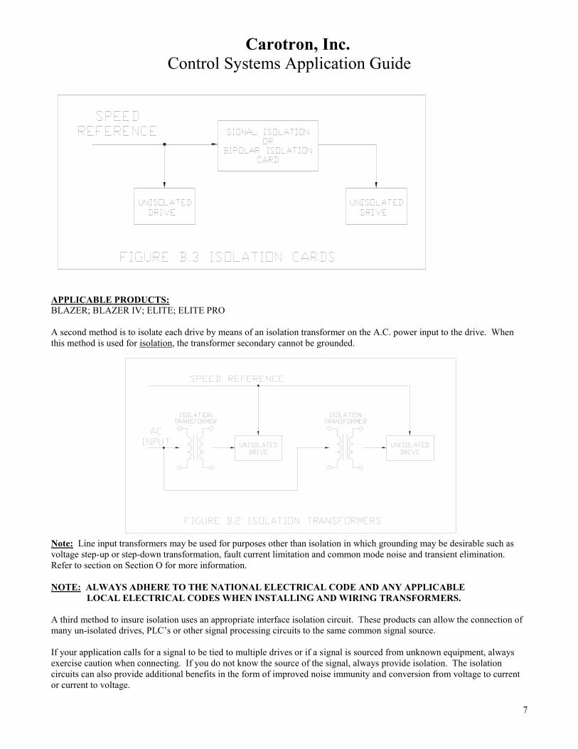
A second method is to isolate each drive by means of an isolation transformer on the A.C. power input to the drive. When
this method is used for isolation, the transformer secondary cannot be grounded.
Note: Line input transformers may be used for purposes other than isolation in which grounding may be desirable such as
voltage step-up or step-down transformation, fault current limitation and common mode noise and transient elimination.
Refer to section on Section O for more information.
NOTE: ALWAYS ADHERE TO THE NATIONAL ELECTRICAL CODE AND ANY APPLICABLE
LOCAL ELECTRICAL CODES WHEN INSTALLING AND WIRING TRANSFORMERS.
A third method to insure isolation uses an appropriate interface isolation circuit. These products can allow the connection of
many un-isolated drives, PLC’s or other signal processing circuits to the same common signal source.
If your application calls for a signal to be tied to multiple drives or if a signal is sourced from unknown equipment, always
exercise caution when connecting. If you do not know the source of the signal, always provide isolation. The isolation
circuits can also provide additional benefits in the form of improved noise immunity and conversion from voltage to current
or current to voltage.
Carotron, Inc.
Control Systems Application Guide
8
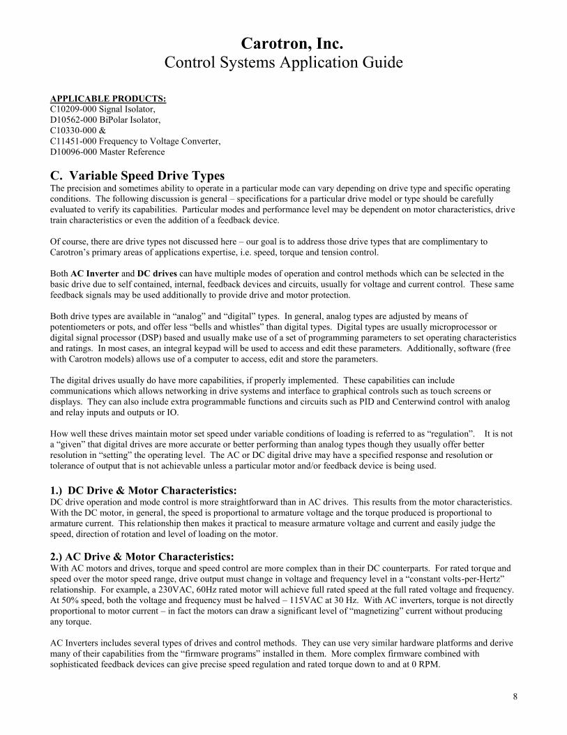
APPLICABLE PRODUCTS: C10209-000 Signal Isolator,
D10562-000 BiPolar Isolator,
C10330-000 &
C11451-000 Frequency to Voltage Converter,
D10096-000 Master Reference
C. Variable Speed Drive Types The precision and sometimes ability to operate in a particular mode can vary depending on drive type and specific operating
conditions. The following discussion is general – specifications for a particular drive model or type should be carefully
evaluated to verify its capabilities. Particular modes and performance level may be dependent on motor characteristics, drive
train characteristics or even the addition of a feedback device.
Of course, there are drive types not discussed here – our goal is to address those drive types that are complimentary to
Carotron’s primary areas of applications expertise, i.e. speed, torque and tension control.
Both AC Inverter and DC drives can have multiple modes of operation and control methods which can be selected in the
basic drive due to self contained, internal, feedback devices and circuits, usually for voltage and current control. These same
feedback signals may be used additionally to provide drive and motor protection.
Both drive types are available in “analog” and “digital” types. In general, analog types are adjusted by means of
potentiometers or pots, and offer less “bells and whistles” than digital types. Digital types are usually microprocessor or
digital signal processor (DSP) based and usually make use of a set of programming parameters to set operating characteristics
and ratings. In most cases, an integral keypad will be used to access and edit these parameters. Additionally, software (free
with Carotron models) allows use of a computer to access, edit and store the parameters.
The digital drives usually do have more capabilities, if properly implemented. These capabilities can include
communications which allows networking in drive systems and interface to graphical controls such as touch screens or
displays. They can also include extra programmable functions and circuits such as PID and Centerwind control with analog
and relay inputs and outputs or IO.
How well these drives maintain motor set speed under variable conditions of loading is referred to as “regulation”. It is not
a “given” that digital drives are more accurate or better performing than analog types though they usually offer better
resolution in “setting” the operating level. The AC or DC digital drive may have a specified response and resolution or
tolerance of output that is not achievable unless a particular motor and/or feedback device is being used.
1.) DC Drive & Motor Characteristics: DC drive operation and mode control is more straightforward than in AC drives. This results from the motor characteristics.
With the DC motor, in general, the speed is proportional to armature voltage and the torque produced is proportional to
armature current. This relationship then makes it practical to measure armature voltage and current and easily judge the
speed, direction of rotation and level of loading on the motor.
2.) AC Drive & Motor Characteristics: With AC motors and drives, torque and speed control are more complex than in their DC counterparts. For rated torque and
speed over the motor speed range, drive output must change in voltage and frequency level in a “constant volts-per-Hertz”
relationship. For example, a 230VAC, 60Hz rated motor will achieve full rated speed at the full rated voltage and frequency.
At 50% speed, both the voltage and frequency must be halved – 115VAC at 30 Hz. With AC inverters, torque is not directly
proportional to motor current – in fact the motors can draw a significant level of “magnetizing” current without producing
any torque.
AC Inverters includes several types of drives and control methods. They can use very similar hardware platforms and derive
many of their capabilities from the “firmware programs” installed in them. More complex firmware combined with
sophisticated feedback devices can give precise speed regulation and rated torque down to and at 0 RPM.

Carotron, Inc.
Control Systems Application Guide
9
Inverters have a large advantage over DC drives and motors when used in “variable” torque applications. Fan and centrifugal
pumps are ideal variable torque loads because their energy consumption varies by the cube of motor speed. For example, a
fan or pump operated at ½ speed will consume only 1/8 the energy of full speed operation. This can result in tremendous
$$$$ savings when applied to HVAC (heating, ventilation and air conditioning) and pumping applications.
3.) Open and Closed Loop Control A “feedback” device in a drive related application refers to a “real time” signal generating device such as an encoder,
tachometer, load cell, photo electric sensor, ultrasonic sensor, dancer pot, current sensor, etc. that provides a return or
feedback signal to the drive system that is used to verify and improve or regulate the process or condition being controlled.
This is known as “closed loop” operation.
AC and DC drives (with associated motors) can usually be operated without an external feedback device. Usually known as
“encoderless” or “open loop” operation in AC drives and AFB or armature feedback in DC drives, these methods of control
usually give lowest performance or regulation.
The feedback device can be specialized to return information on a particular aspect of the system operation. This could be
velocity, torque, tension, position, level, etc. or combinations. For example, a specific type of encoder could provide both
motor velocity and shaft position feedback. With most motor drives, a velocity feedback can be accepted and processed
directly to improve speed regulation by compensating for design inefficiencies or losses in the motor, ambient and motor
temperature change, AC line voltage changes and load change.
Additionally, the same feedback encoder (or other feedback device) signal can be used as a reference signal for another drive
or process in a follower application. Isolation may be an issue to be addressed in this situation.
The function of a tachometer or encoder, i.e. whether it is a feedback or reference supplying device, can cause very diverse
symptoms in the event of device failure. For example, loss or partial loss of a drive velocity feedback signal may be
interpreted by the drive as “motor running too slow”. In this case, the drive could compensate by increasing motor speed or
“run away” in an attempt to raise the feedback to an expected level. Loss of signal from the same device used as a source of
speed reference could cause the follower drive and motor to slow or stop.
Be aware that some analog drives will directly accept velocity feedback from an encoder. The use of “encoder feedback” on
these drives does not imply “digital” accuracy. In these drives, the encoder signal is converted to a voltage signal and then
used in place of a tachometer feedback signal.
D. Drive Operating Modes Control of motor torque and velocity or speed are operating mode selections available to most basic DC drives and to some
flux vector type AC drives. With some products, Velocity mode operation can include capacity for regeneration.
1.) DC Drives – Torque Control: To control motor torque, a DC drive will regulate armature current.

Carotron, Inc.
Control Systems Application Guide
10
The armature voltage is unregulated allowing the motor to operate at whatever speed is necessary to achieve the set current
/torque level. Such a set-up may be used for any constant torque drive rolls and simple winders to adjust approximate tension
for small build ratio centerwind operation. For torque mode center winders and a fixed input reference, torque remains
constant giving a taper tension effect unless the machine operator increases the torque set-point as diameter increases.
Straight torque control can have the undesirable effect of causing run-up to maximum speed in the event of web breakage or
load loss unless the drive includes a “Max speed or voltage limiting” function.. These effects can be compensated for by
optional drive add-on boards and/or external control circuits to give full featured “constant tension center wind”, CTCW,
control with included compensation for friction, inertia, diameter change and more. Some drives such as the Carotron ELITE
PRO, digital DC drive, include CTCW firmware.
APPLICABLE PRODUCTS:
TROOPER SERIES
ADP100 SERIES
BLAZER SERIES
ELITE SERIES
CHOICE SERIES
ELITE PRO SERIES
2.) AC Drives – Torque Control: An AC drive uses complex processing of motor voltage, current, frequency and rotational position to give it torque regulation
capability. TORQUE mode operation usually requires encoder feedback. Even evaluation of an inverter drive’s torque
regulation ability is not a straightforward task. Do not assume that an inverter and motor operating in “torque” mode will
produce a linear and proportional output torque versus reference. Complete torque control may be dependent on the use of an
external torque reference circuit or control that has flexibility and adjustability to compensate for any drive/motor
shortcomings.
3.) DC Drives – Velocity (Speed) Control: To regulate DC motor speed, the drive will normally control the armature voltage. How well it does this depends on what
feedback signal is used to represent the motor speed. Refer to the Section C, “Open Loop and Closed Loop Control”.
Common selections for some DC drives are as follows: A. AFB – Armature feedback
B. TFB – Tachometer feedback
C. EFB – Encoder feedback
A.) AFB – Armature Feedback
The armature voltage feedback method, also called armature feedback, relies on the ability of a DC motor to act as a DC
generator. When a DC motor is rotated, it will generate a voltage level called counter or back emf that is proportional to
the speed of rotation. As on all “generators”, the generated output is also affected by the strength of the field magnetic flux.
Carotron, Inc.
Control Systems Application Guide
11
Since the armature voltage coming from the drive is output in the form of pulses, the counter emf voltage can be measured in
between the pulses. This signal is then introduced to the speed regulation circuit of the drive, the Velocity Loop, to adjust the
drive power section to maintain a constant motor voltage. The primary benefit of armature feedback is that (with Carotron
DC drives) no additional drive or motor components are required.
Some problems associated with Armature Feedback operation are related to certain DC motor characteristics. One problem
is, even with constant armature voltage the motor speed may drop several percent when the motor is loaded. This drop is due
to “internal resistance” losses in the motor armature and is addressed on DC drives by the addition of a “internal resistance
compensation”, IR Comp, pot and signal.
The IR Comp circuit senses load increase and then increases armature voltage to prevent speed droop. Unfortunately, the
effect of IR losses is not usually the same over the motor speed range and a specific IR Comp setting works best at a specific
motor speed.
Another problem with Armature Feedback relates to the motor operation as a “generator” and how that is affected by the field
magnetic flux strength. On the wound electromagnetic field(s) of Shunt Field motors, temperature increase as the motor
warms up (immediately after power up) will cause the field winding resistance to increase. This causes a decrease in field
current and flux strength which in turn causes a decrease in generated voltage which when used as velocity feedback causes
an increase in motor speed as the drive tries to maintain a constant armature voltage feedback.
The influence of shunt field strength on DC motor speed and torque can be used to advantage in some applications –
primarily known as “CONSTANT HORSEPOWER” applications. In these applications, speed can be “swapped” for
torque to deliver high torque at low speed and high speed at low torque. A Velocity Mode Center Winder is an example
application where low torque and high speed are required on a beginning roll and as diameter increases; rotational speed
decrease is accompanied by an increasing torque requirement. In higher HP applications using specially designed motors,
usually > 5 HP, control of the DC motor field can be provided by the drive or by an independent FIELD REGULATOR.
Refer to Section H. Constant Horsepower Winders for more detailed description of this type of operation.
APPLICABLE PRODUCTS:
FR1000 & FR3500 FIELD REGULATOR CONTROL
ELITE PRO SERIES
Permanent magnet, PM, field motors do not experience the “field flux change” phenomena but can still exhibit the IR losses.
So, armature feedback operation is less costly but, the potential associated problems may be prohibitive if precise regulation
over the motor speed range and drift-free operation is required. The way to eliminate these potential problems is to “close the
velocity loop” by use of an external feedback device such as a tachometer or encoder.
B.) TFB –Tachometer Feedback
Tachometers and encoders are devices that give a precise output that is proportional to their speed of rotation. Use of such a
device for feedback is called “closed loop operation”.
Tachometers (also known as Tachs or tach generators) are varied and are rated in Volts-per-1000RPM. Most of them supply
a DC voltage output but, AC voltage rated units are still available and used.
Some standard DC ratings are 7, 50 and 100 VDC/1000RPM. Standard AC ratings are 45 and 90 VAC/1000RPM. The AC
tachometer output changes in frequency and voltage level with speed change.

Carotron, Inc.
Control Systems Application Guide
12
C.) EFB – Encoder Feedback
Encoders come in an even larger variety of ratings and output a signal that increases in frequency with speed increase. They
can be specified with multiple outputs called quadrature outputs and marker pulses which permit them to feed back direction-
of-rotation and rotational position information.
Some encoders are referred to as Pulse Tachs or Pulse Generators. These are usually “ring and gear” or “Hall sensor and
Magnet wheel” arrangements that mount to a “C” face or flange on the motor. All encoders are specified in Pulses-per-
Revolution or PPR and may have output ratings from 1PPR to thousands of PPR.
Tachometers and Encoders include ratings for output accuracy or tolerance, supply requirements, temperature range and load
range. Their main claim to fame is that they ignore most external influences and give an accurate and repeatable output as
long as they’re operated within their defined ratings. This means that drives using them for feedback also can ignore or
compensate for factors including motor losses, line voltage fluctuation, load change and temperature change.
APPLICABLE PRODUCTS:
TCF60 & TCF120 SERIES PULSE TACHS
TAC008-000 XPY FLANGE ENCODER
TAC017-000 QUADRATURE RING ENCODER
4.) AC Drives – Velocity (Speed) Control: AC Inverter drives can have several selectable control methods. Some examples are:
A.) V/F Control
B.) V/F Control with PG or Tachometer Feedback
C.) Open Loop Vector
D.) Closed Loop or Flux Vector
A.) The V/F, voltage/frequency, Control method – also called Volts-per-Hertz control is the most common inverter control
method. Requiring no feedback device, it is suitable for general purpose and multiple motor applications.
B.) V/F Control with PG Feedback gives the better speed regulation of a closed loop system.
C.) Open Loop Vector, sometimes called sensorless vector, utilizes a more complex control algorithm to give precision
speed control, quick response and higher torque at low speed.

Carotron, Inc.
Control Systems Application Guide
13
D.) Flux Vector or closed loop vector requires encoder feedback and gives precise speed and full rated torque control over a
wide speed range – sometimes even at zero RPM.
Inverters and their motors can also be operated in a “Constant Horsepower” profile where motor speed can be extended
beyond the base speed rating with torque capacity de-rating. Refer to Section H.12, “Constant Horsepower Winders” for
more detailed description of this type of operation.
5.) Regeneration: Regeneration relies on the ability of both AC and DC motors to act as generators as well as motors. Regeneration is an
operating mode that is automatically implemented by a REGEN drive’s velocity control section whenever the velocity
feedback is greater than the velocity reference. With regenerative drive capacity, a motor can provide motoring (positive)
torque or braking (negative) torque, usually in either direction of rotation. This is called “four quadrant” operation. Non-
regenerative drives provide only “single quadrant” operation although the addition of reversing contactors with DC drives
can allow motoring operation in the third quadrant.
So with motoring operation, power is taken from the AC line and converted to produce work by the motor. With regen
operation, self generated power is taken from the motor and fed back to the AC line or energy dissipating “brake resistors” to
produce negative or braking torque in the motor. This function is useful when dealing with high inertia or overhauling motor

Carotron, Inc.
Control Systems Application Guide
14
loads. With DC drives, regenerative capability also provides “solid state reversing”. Without regeneration, DC rated
contactors must be used for reversing. Frequent reversing, even at low load levels, can cause short mechanical life
expectancy on contactors. With a regen drive, only a single contactor is recommended for “fail safe stopping”.
“Regen” capability in a DC drive requires a second power section and more control circuitry than in a non-regen type while
most AC Inverter drives inherently include some regeneration capability. Most lower HP rated AC drives also come with the
“braking transistor” circuitry required for expanding regen capability with the addition of only the braking resistor.
Additionally, some AC drives may include “line regen” capability where the excess motor energy is fed back into the line
instead of being dissipated across resistors. DC regenerative drives can typically deliver higher continuous negative torque
than an inverter drive using a braking resistor. The inverter braking transistor and resistor continuous wattage ratings will
determine the operating duty cycle.
APPLICABLE PRODUCTS:
D10425-XXX SERIES
TROOPER IV
RCP200 SERIES
BLAZER IV SERIES
ELITE PRO SERIES
E. Multiple Drives – Coordinated Control: There are several methods for controlling multiple drives and each has inherent advantages and disadvantages. A primary
determining factor for selection concerns whether we’re dealing with a continuous web or length of product as opposed to
individual or “parallel” processes occurring at the same time.
Our discussion will address several methods of coordinated control:
1.) Basic Follower
2.) Cascaded Follower
3.) Frequency Follower
4.) Follower Mode Negatives
5.) PID Control
6.) Process Control Interface
7.) Transmitter/Receiver
8.) Master Reference (Parallel) Control
9.) Inverted Logic Follower
1.) Basic Follower: A Leader/Follower scheme remains one of the most cost effective and adaptable methods for coordinated control of two or
more drives in a continuous web operation. Carotron’s System Interface function products include input capability for
Frequency, Voltage and Process Current signals and all provide external TRIM pot connections and TRIM RANGE setting
adjustments.
Carotron, Inc.
Control Systems Application Guide
15
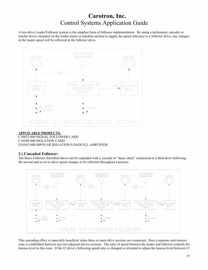
A two drive Leader/Follower system is the simplest form of follower implementation. By using a tachometer, encoder or
similar device mounted on the leader motor or machine section to supply the speed reference to a follower drive, any changes
in the leader speed will be reflected in the follower drive.
APPLICABLE PRODUCTS:
C10032-000 SIGNAL FOLLOWER CARD
C10209-000 ISOLATION CARD
D10562-000 BIPOLAR ISOLATION/LOADCELL AMPLIFIER
2.) Cascaded Follower: The Basic Follower described above can be expanded with a cascade or “daisy chain” connection to a third drive following
the second and so on to allow speed changes to be reflected throughout a process.
This cascading effect is especially beneficial when three or more drive sections are connected. Here a separate web tension
zone is established between any two adjacent driven sections. The ratio of speed between the leader and follower controls the
tension level in this zone. If the #2 drive’s following speed ratio is changed or trimmed to adjust the tension level between #1

Carotron, Inc.
Control Systems Application Guide
16
and #2, the #3 drive will follow the change and the tension level in the zone between #2 and #3 will not be changed. In other
words, the cascading effect allows changes to be reflected “downstream” in the web path without the need to correct all
follower drive trim ratios.
APPLICABLE PRODUCTS:
C10032-000 SIGNAL FOLLOWER CARD
C10209-000 ISOLATION CARD
D10562-000 BIPOLAR ISOLATION/LOADCELL AMPLIFIER
3.) Frequency Follower: As mentioned previously, with some drives, encoders or pulse tachometers can be used in place of DC tachometers. With
some “tachometer feedback only” drive models, one of Carotron’s Frequency to Voltage converter cards can convert
frequency signals to analog voltages suitable for tachometer feedback control and/or speed reference in motor control
systems.
APPLICABLE PRODUCTS:
C10330-000 FREQUENCY TO VOLTAGE CONVERTER
C11451-000 FREQUENCY TO VOLTAGE CONVERTER
4.) Follower Mode Negatives: There are a couple of “negatives” related to follower applications.
First, because any regulation errors by individual drives would be cumulative, multiple steps of cascading may produce more
accumulated error than the process can tolerate. For example; in the three drive system described above, assume 0.5%
regulation error in the two follower drives for a 1% total system error.
Carotron, Inc.
Control Systems Application Guide
17
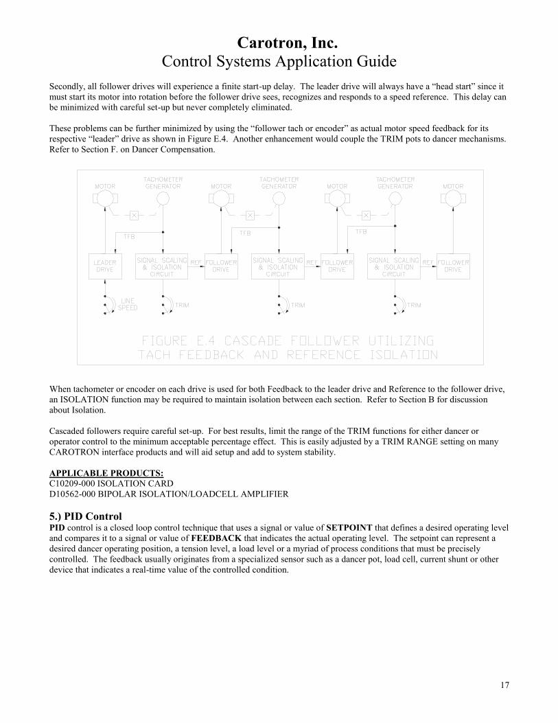
Secondly, all follower drives will experience a finite start-up delay. The leader drive will always have a “head start” since it
must start its motor into rotation before the follower drive sees, recognizes and responds to a speed reference. This delay can
be minimized with careful set-up but never completely eliminated.
These problems can be further minimized by using the “follower tach or encoder” as actual motor speed feedback for its
respective “leader” drive as shown in Figure E.4. Another enhancement would couple the TRIM pots to dancer mechanisms.
Refer to Section F. on Dancer Compensation.
When tachometer or encoder on each drive is used for both Feedback to the leader drive and Reference to the follower drive,
an ISOLATION function may be required to maintain isolation between each section. Refer to Section B for discussion
about Isolation.
Cascaded followers require careful set-up. For best results, limit the range of the TRIM functions for either dancer or
operator control to the minimum acceptable percentage effect. This is easily adjusted by a TRIM RANGE setting on many
CAROTRON interface products and will aid setup and add to system stability.
APPLICABLE PRODUCTS:
C10209-000 ISOLATION CARD
D10562-000 BIPOLAR ISOLATION/LOADCELL AMPLIFIER
5.) PID Control PID control is a closed loop control technique that uses a signal or value of SETPOINT that defines a desired operating level
and compares it to a signal or value of FEEDBACK that indicates the actual operating level. The setpoint can represent a
desired dancer operating position, a tension level, a load level or a myriad of process conditions that must be precisely
controlled. The feedback usually originates from a specialized sensor such as a dancer pot, load cell, current shunt or other
device that indicates a real-time value of the controlled condition.

Carotron, Inc.
Control Systems Application Guide
18
The PID control’s primary function is to provide an output correcting signal or value that minimizes the error or difference
between the SETPOINT and FEEDBACK. The expression PID is derived from Proportional, Integral and Derivative
processing of the error signal. The presence, polarity, amplitude and rate of change of the error signal initiate and direct the
processing techniques. The polarity is determined by the greater of the setpoint or feedback values and determines whether
the corrections are increasing or decreasing or adding or subtracting signals.
In Carotron products, the three correction signals are independently adjusted and then are summed together, sometimes with
other signals, to produce a complete control signal. In set-up these signals should be initially implemented and adjusted in
the “P.I.D.” order with Proportional first, Integral second and Derivative last if at all.
Proportional Processing
Proportional correction is produced immediately from the presence and polarity of an error signal. The level of the
correction is based on an adjustable value of gain. Most basic signal conditioning circuits provide outputs that are
proportional to their inputs.
Integral Processing
The Integral correction signal is also based on the presence and polarity of the error signal. Depending on the product, it
uses an adjustable rate or time of response to produce a signal that will continually increase or decrease (based on the
polarity) until the error returns to a minimum level. The integral signal will then “hold" at this level as long as the error
remains at minimum. It is the only of the three signals present when there is no longer any error.
The change in level is usually produced at a linear rate which provides a predictable and stable response in most process
control applications. Some Carotron PID control products offer a second mode of integral correction where the rate of
change is dependent on the amount of error (the greater the error, the faster the integration rate).
Our PID products also include a Deadband adjustment that sets a + “null level” of error that must be exceeded before the
Integrator will respond. This is helpful for stabilizing operation in applications that are handling out-of-round material rolls
or bent transport rolls.
Derivative Processing The amount of Derivative correction is based on the rate of change of the error signal. A faster rate of change will produce a
greater correction. It is produced only while the error is changing. Care should be used in implementing Derivative
correction because its affect can change with large changes in the dynamics of an application such as with a large diameter
and mass change on a center driven roll.
All Carotron PID function controls include some unique functions utilizing SCALING INPUT and SUMMING INPUT.
These inputs provide ease in combining an optimized PID correction signal with a primary reference signal and even ranging
the effect of the correction by the primary reference. For example: a dancer position correction may be scaled to provide +
10% speed trim when a line is operated at 100% speed but, when the line runs at 10% speed, the same dancer trim equates to
100% trim! In other words, the dancer trim range % (and sensitivity) increases as line speed decreases. This can mean

Carotron, Inc.
Control Systems Application Guide
19
different dancer response and stability at different line speeds. Use of the SCALING function will range the correction
signal so that a constant percentage of SET speed is maintained.
APPLICABLE PRODUCTS: CLT2000-000 CORTEX LT CONTROLLER
D10541-000 DANCER POSITION/PID CARD
MM3000-PID MICROMANAGER PID CONTROL
6.) Process Control Interface: Most applications involving “process control” utilize sensing and monitoring of specific aspects of the process or end
product. In many cases the sensors used provide output in the form of low level millivolt or milliampere signals which will
normally require conversion, amplification, scaling and isolation to a level that is practical for use by a drive or control
circuit.
Devices such as current shunts typically supply only +50 or +100 millivolts full scale output but may be at hundreds of volts
potential to ground or to un-isolated circuit inputs. Load cells or tension transducers are also low output devices commonly
used in process control.
In some cases sensors already supply a “process output” signal such as 4 – 20 milliamps for full range output but, the actual
operating range is only a fraction of the sensor range. For example; a 1000 pound scale may be used to weigh product no
greater than 500 pounds so we only see 12 milliamps maximum.
Carotron offers products providing these input/output capabilities, isolation and bi-polar signal processing. For example, the
Model D10562-000, Bipolar Isolation Card, can accept any of the Input signals and can generate any of the Output signals
listed below.
Typical Input Signals: Typical Output Signals:
0 – 5 mA 0 – 5 mA
1 – 5 mA 1 – 5 mA
0 – 20 mA 0 – 20 mA
4 – 20 mA 4 – 20 mA
0 – +50 mV 0 – +10 VDC
0 – +100 mV +10 – 0 VDC
0 – +10 VDC -10 VDC - +10 VDC
0 – +25 VDC
0 – +100 VDC
0 – +200 VDC
0 – +250 VDC
Since the output of these circuits is proportional to the input, they can sometimes be used as simple controls where a direct
action proportional to the input must take place. Quite often their outputs are used as the feedback to a PID controller to give
precise control of the process variable being sensed. Refer to Section E.5 on PID Control. Some examples follow:

Carotron, Inc.
Control Systems Application Guide
20
APPLICABLE PRODUCTS:
C10209-000 ISOLATION CARD
D10562-000 BIPOLAR ISOLATION/LOADCELL AMPLIFIER

Carotron, Inc.
Control Systems Application Guide
21
6.) Transmitter/Receiver Control: A very specialized form of follower is the Transmitter/Receiver configuration shown in Figure E.9.
This scheme can be used to follow or allow control by a low level voltage signal whose source is too remote to allow the use
of a standard voltage follower. Typically, voltage signals are fed into high input impedance circuits to prevent excess loading
and distortion of the signal. When long wire runs are used to carry these signals, several problems can occur.
1. The long lead wire can act as an antenna which picks up or receives radiated RF or transient energy.
2. The resistance of the lead wire can cause voltage drops in the transmitted signal that distort or alter its true character.
3. The capacitance of the lead wire can cause signal delays or filtering action that distort or alter signal character.
By converting the voltage signal to a process signal of 4 to 20 mA, the reference can be transmitted over much longer
distances through twisted pair cable and be converted back to isolated voltage at the receiving end. By transmitting the signal
as a higher power “process current” level, the effects mentioned above can be minimized or eliminated.
APPLICABLE PRODUCTS:
C10032-000 SIGNAL FOLLOWER CARD
C10209-000 ISOLATION CARD
7.) Master Reference (Parallel Control): In a Master Reference application, a primary control signal such as a master pot., tachometer, process signal or frequency
signal is used to control the speed of two or more motors. The start-up delays associated with the cascade follower systems
are effectively eliminated since the individual drives receive start-up commands and reference signals at the same time while
remaining electrically isolated from each other and the source of reference.
Master Reference control is also appropriate for non-web applications such as metering pumps or feeder controls where
precise mix percentages must be adjustable and maintained over the system speed range. Figure E.10 illustrates shows the
Master Reference control being used to regulate speed and mix ratios for the contents of asphalt in a hot mix plant
application. Here the manually set speed ratios are maintained over the plant operating speed range.

Carotron, Inc.
Control Systems Application Guide
22
Also included are acceleration and deceleration adjustments for use with a master potentiometer input. Using the master
ramp function is very desirable to produce orderly start and ramp-to-stop functions by controlling the acceleration and
deceleration time required by the system. Without this feature it would be necessary to match the acceleration and
deceleration rates of the individual drives which can be difficult.
One shortcoming of the MASTER REFERENCE control scheme for continuous web applications is that any speed trim
initiated for individual drives and any speed change due to load will not be automatically reflected in other “down-stream”
drives of the process.
When handling a continuous web, the MASTER configuration is best applied in applications where one of the following
situations exists.
1. With no other method of compensation; the material being processed must be of sufficient strength that it can withstand
considerable tension due to regulation differences between the individual drives.
2. The objective of the control is in fact pure velocity control of the individual motors and the web is expected to be affected
by the differences - such as in progressive draw applications.

Carotron, Inc.
Control Systems Application Guide
23
APPLICABLE PRODUCTS:
D10096-000 MASTER REFERENCE UNIT
8.) Inverted Logic Follower:
A few applications call for inverted logic. Most signal conditioning circuits will give an increasing output with an increasing
input. Inverted logic will give a decreasing output with increasing input. This capability is available in several standard
Carotron products as an optional calibration set-up. It is generally used as a very simple “proportional” control method for
non-critical applications.
For Example: A drive used for a pump control or feeder control can be set to operate at a maximum speed with light load or
pressure. An increasing signal from a load sensor or pressure transducer, etc. can cause a proportional decrease in motor
speed until a balance is achieved – within the defined operating range.
APPLICABLE PRODUCTS:
C10032-000 SIGNAL FOLLOWER CARD
C10209-000 ISOLATION CARD
F. Dancer Compensation In general, dancer or compensator mechanisms and their position sensors are incorporated into velocity mode drive
applications for several reasons:
They can provide accumulation or storage of material. When located between two driven sections of a process that may
accelerate or decelerate at different rates, the dancer can absorb or store excess material or give up stored material to provide
a more stable operating tension level.
How much material a dancer can store in its acceptable range of movement is “running time storage”. More running time
storage allows longer response times in the controlled drives and motors and usually results in more stable operation.
With a conventional gravity operated “swing arm” type dancer, maximum storage equals the length of web material required
to drop the dancer from its highest possible position to its lowest possible position. This range of movement is rarely
acceptable in real life and would usually cause a dancer “travel limit” fault to occur. True “running time storage” is the
length stored in the range of movement that is acceptable by the person(s) qualifying successful operation. Systems
supplying 0.5 to 1.0 second or greater running time storage seldom encounter set-up difficulties though less storage can still
be successful with careful adjustment and by minimizing the range of the dancer control circuit.
Since the force exerted by a dancer sets the Tension in the zone where it’s located, the dancer can be used as a direct
TENSION controlling device when used with adjustable weights, counter weights or pneumatically controlled actuators.
Electrically controlled pneumatics can be used to provide Taper Tension control.
1.) Dancer Utilization: How dancer compensation can best be utilized depends on the answers to several questions:
A.) What is used as the dancer position sensor and what kind of signal does it provide?
B.) Will the dancer provide 100% of the reference signal to the drive being controlled or will it be used to provide a
lower percentage correction or trim?
C.) What is the material maximum “line” speed and how much running time storage is provided by the dancer
mechanism?
D.) Will the dancer provide a fixed or variable operating tension level and is TAPER tension control required?
The following discussion addresses many of these questions.
2.) Dancer Sensors: The most common sensor used to signal the dancer position is a potentiometer. There are many “pot” types with different
materials and construction features used in their manufacture. Unfortunately, standard pots meant for manual operation are
often used in these applications with several negative results:
Carotron, Inc.
Control Systems Application Guide
24
A.) Limited life expectancy due to excess wear of the resistance element. Dancer pots, unlike manual pots, are
rotated very frequently if not continuously during their operating life. When used successfully with dancer position
or PID circuits, their wear is actually concentrated around a single spot in their rotation range which greatly
increases the equivalent number of rotations.
B.) Limited life expectancy due to excess wear of the shaft bushing. Dancer pots are usually coupled to the pivot
point shaft of the dancer mechanism by a sprocket and chain or gear and timing belt arrangement. Tightening the
belt or chain to prevent “lost motion” causes lateral wearing forces on the bushing not usually seen with a manually
operated knob.
C.) Limited life expectancy due to rotation beyond physical limits. Most conventional pots have a 270 degree
electrical and mechanical rotation. The pots have physical rotation “stops” integrated into their construction – a
good thing with a manual adjustment but very bad when the pot becomes the travel limiter for a dancer mechanism.
Carotron, Inc. addresses and solves each of these problems in our DANCER DUTY POTENTIOMETER series of products
and with our NON-CONTACT SENSOR products.
APPLICABLE PRODUCTS:
WDDC1 & WDDC2 WASHDOWN DUTY DANCER, PROCESS CURRENT SENSOR SERIES
WDDV1 & WDDV2 WASHDOWN DUTY DANCER, VOLTAGE OUTPUT SENSOR SERIES
NCD01 & NCD02 NON-CONTACT DANCER SENSOR SERIES
DDP01 & DDP02 DANCER DUTY POT SERIES
3.) Dancer Mechanical Performance: How the dancer operates mechanically will significantly affect its ability and stability of control. The dancer mechanism
must move freely and track robustly with the material. Pneumatics used to control dancer operating force must not restrict or
dampen movement with a “shock absorber” effect.
The dancer sensor, whether a potentiometer, non-contact sensor, ultrasonic sensor or other, must be driven by the dancer in
an optimum fashion. For example: a pivot type dancer with 30 degrees of movement should not be direct coupled to a dancer
duty potentiometer with 300 degrees electrical range. This would produce only 10% of the possible signal change and will
reduce resolution of the dancer. The pot should be driven by gearing that will maximize sensor output over the dancer range
of travel.
There must be NO movement of the dancer that is not reflected or indicated by signal change from the sensor. Loose
couplings, chains, timing belts, sprockets, gears, etc. used to translate dancer movement to sensor output can result in poor
dancer system performance if not outright instability.
4.) Dancer Control Techniques: The following lists several ways dancers are used to provide control.
A.) Dancer Trim
B.) Shunt Field Trim by Dancer
C.) PID Trim Control
D.) PID 100% Control
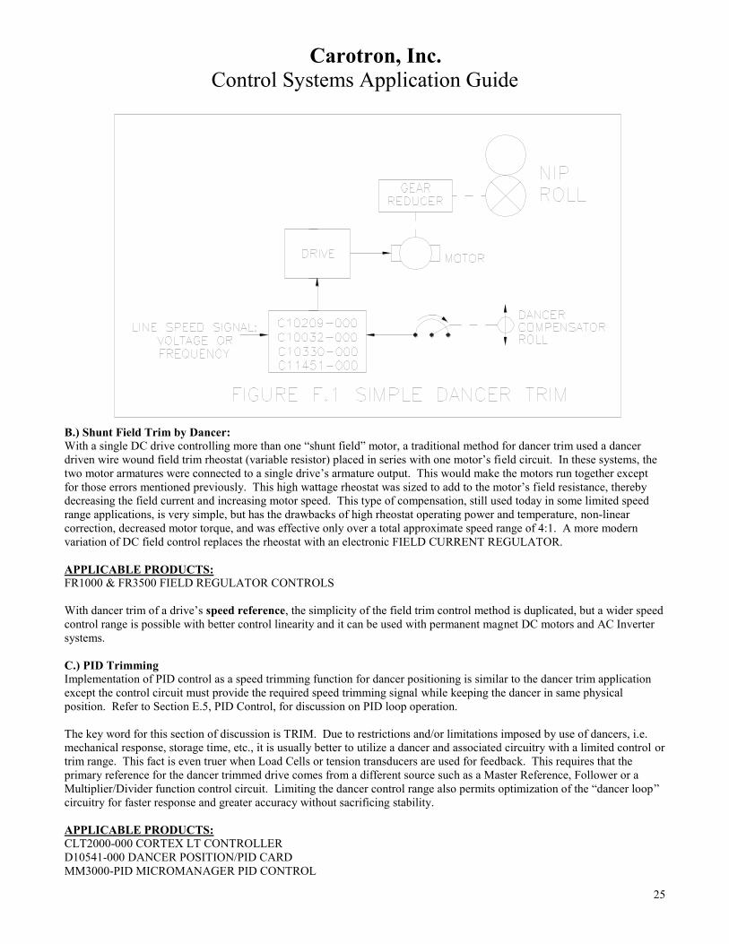
A.) Dancer Trim
The purpose of a Dancer Trim function is to provide a small speed correction between two driven points on a web. An
“actual speed” signal, taken from the leader drive, will be trimmed by the dancer mechanism with its associated position
sensor. Operation is much like a Basic Follower scheme except that the TRIM function is implemented by a mechanical
dancer mechanism instead of manually.
Without dancer compensation, a speed mis-match may result from differences in loading and in acceleration and deceleration
times or may come from individual drive speed regulation errors. In a dancer compensated system, when follower speed
errors occur, the dancer is pulled out of position until it produces a countering and balancing speed trimming signal. The
exact position of the dancer may change at different set speeds but is usually consistent at a given speed.
Carotron, Inc.
Control Systems Application Guide
25
B.) Shunt Field Trim by Dancer:
With a single DC drive controlling more than one “shunt field” motor, a traditional method for dancer trim used a dancer
driven wire wound field trim rheostat (variable resistor) placed in series with one motor’s field circuit. In these systems, the
two motor armatures were connected to a single drive’s armature output. This would make the motors run together except
for those errors mentioned previously. This high wattage rheostat was sized to add to the motor’s field resistance, thereby
decreasing the field current and increasing motor speed. This type of compensation, still used today in some limited speed
range applications, is very simple, but has the drawbacks of high rheostat operating power and temperature, non-linear
correction, decreased motor torque, and was effective only over a total approximate speed range of 4:1. A more modern
variation of DC field control replaces the rheostat with an electronic FIELD CURRENT REGULATOR.
APPLICABLE PRODUCTS:
FR1000 & FR3500 FIELD REGULATOR CONTROLS
With dancer trim of a drive’s speed reference, the simplicity of the field trim control method is duplicated, but a wider speed
control range is possible with better control linearity and it can be used with permanent magnet DC motors and AC Inverter
systems.
C.) PID Trimming
Implementation of PID control as a speed trimming function for dancer positioning is similar to the dancer trim application
except the control circuit must provide the required speed trimming signal while keeping the dancer in same physical
position. Refer to Section E.5, PID Control, for discussion on PID loop operation.
The key word for this section of discussion is TRIM. Due to restrictions and/or limitations imposed by use of dancers, i.e.
mechanical response, storage time, etc., it is usually better to utilize a dancer and associated circuitry with a limited control or
trim range. This fact is even truer when Load Cells or tension transducers are used for feedback. This requires that the
primary reference for the dancer trimmed drive comes from a different source such as a Master Reference, Follower or a
Multiplier/Divider function control circuit. Limiting the dancer control range also permits optimization of the “dancer loop”
circuitry for faster response and greater accuracy without sacrificing stability.
APPLICABLE PRODUCTS: CLT2000-000 CORTEX LT CONTROLLER
D10541-000 DANCER POSITION/PID CARD
MM3000-PID MICROMANAGER PID CONTROL
Carotron, Inc.
Control Systems Application Guide
26
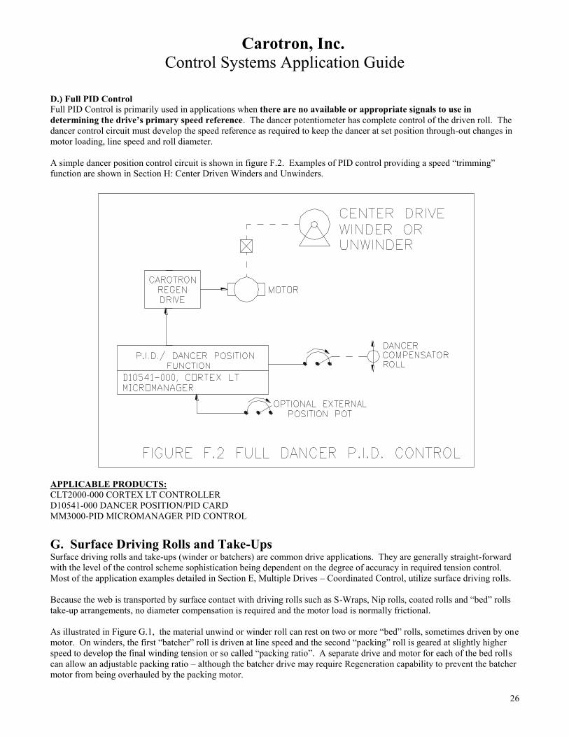
D.) Full PID Control
Full PID Control is primarily used in applications when there are no available or appropriate signals to use in
determining the drive’s primary speed reference. The dancer potentiometer has complete control of the driven roll. The
dancer control circuit must develop the speed reference as required to keep the dancer at set position through-out changes in
motor loading, line speed and roll diameter.
A simple dancer position control circuit is shown in figure F.2. Examples of PID control providing a speed “trimming”
function are shown in Section H: Center Driven Winders and Unwinders.
APPLICABLE PRODUCTS: CLT2000-000 CORTEX LT CONTROLLER
D10541-000 DANCER POSITION/PID CARD
MM3000-PID MICROMANAGER PID CONTROL
G. Surface Driving Rolls and Take-Ups Surface driving rolls and take-ups (winder or batchers) are common drive applications. They are generally straight-forward
with the level of the control scheme sophistication being dependent on the degree of accuracy in required tension control.
Most of the application examples detailed in Section E, Multiple Drives – Coordinated Control, utilize surface driving rolls.
Because the web is transported by surface contact with driving rolls such as S-Wraps, Nip rolls, coated rolls and “bed” rolls
take-up arrangements, no diameter compensation is required and the motor load is normally frictional.
As illustrated in Figure G.1, the material unwind or winder roll can rest on two or more “bed” rolls, sometimes driven by one
motor. On winders, the first “batcher” roll is driven at line speed and the second “packing” roll is geared at slightly higher
speed to develop the final winding tension or so called “packing ratio”. A separate drive and motor for each of the bed rolls
can allow an adjustable packing ratio – although the batcher drive may require Regeneration capability to prevent the batcher
motor from being overhauled by the packing motor.

Carotron, Inc.
Control Systems Application Guide
27
There are many variations on this type of take-up. Reversing is sometimes required in order to allow the web to be processed
“face in” or “face out”. The reverse function is sometimes utilized to Reverse Jog the take-up to remove sections of the web
as in inspection equipment. Note that the “batcher” and “packing” roll functions must swap positions if significant yardage is
wound in the reverse direction.
The illustration depicts a typical surface control scheme. A dancer mechanism sets web tension, provides accumulation and
controls regulation during acceleration and deceleration. With this dancer scheme, a parallel reference system from a master
reference unit is utilized. The Nip rolls set line speed and are not trimmed.
In some cases of relatively low line speed, slow acceleration, and when handling a web not sensitive to tension, the dancers
may be omitted in favor of manual trim pots. These pots should be limited in total range and should be multi-turn types to
prevent the operator from introducing sudden large speed changes.
H. Center Driven Winders and Unwinders
1.) General Characteristics: The older persons among us are familiar with cassette tapes and perhaps even reel-to-reel recorders. These devices both used
a center driven winder and unwinder and included a constant speed capstan drive between the two. The winder or take-up
reel started at a fast speed due to its small diameter and slowed as diameter increased. The unwinder or supply reel of course
started full/slow and ended up small/fast. This operation appeared to be very simple. Recording tape is relatively strong and
requires little tension control.
In industrial center winder/unwinder applications, the web material may not tolerate much change in tension although when
transporting material at Constant Tension, the motor speed and torque must change to keep tension and surface speed
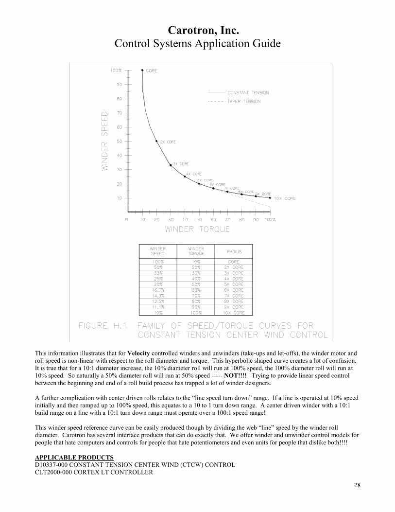
constant. Refer to the Speed/Torque curves and chart in Figure H.1.
Carotron, Inc.
Control Systems Application Guide
28
This information illustrates that for Velocity controlled winders and unwinders (take-ups and let-offs), the winder motor and
roll speed is non-linear with respect to the roll diameter and torque. This hyperbolic shaped curve creates a lot of confusion.
It is true that for a 10:1 diameter increase, the 10% diameter roll will run at 100% speed, the 100% diameter roll will run at
10% speed. So naturally a 50% diameter roll will run at 50% speed ----- NOT!!!! Trying to provide linear speed control
between the beginning and end of a roll build process has trapped a lot of winder designers.
A further complication with center driven rolls relates to the “line speed turn down” range. If a line is operated at 10% speed
initially and then ramped up to 100% speed, this equates to a 10 to 1 turn down range. A center driven winder with a 10:1
build range on a line with a 10:1 turn down range must operate over a 100:1 speed range!
This winder speed reference curve can be easily produced though by dividing the web “line” speed by the winder roll
diameter. Carotron has several interface products that can do exactly that. We offer winder and unwinder control models for
people that hate computers and controls for people that hate potentiometers and even units for people that dislike both!!!!
APPLICABLE PRODUCTS D10337-000 CONSTANT TENSION CENTER WIND (CTCW) CONTROL
CLT2000-000 CORTEX LT CONTROLLER

Carotron, Inc.
Control Systems Application Guide
29
MM3000-CTCW MICROMANAGER CTCW CONTROL
The story changes for Torque controlled center-winders. In general, Torque Mode operation is appropriate when the web is
processed at a finite tension level (as opposed to tensionless). For Constant Tension control, the web “tension setting
torque” delivered by the winder motor must increase directly in proportion to the roll diameter. This is a very linear
relationship.
One problem with all of this is that some materials cannot be wound in nice tight packages with straight edges and constant
width – when tension is held constant!!! The problem becomes visible in the form of distortion in the finished roll. One
phenomenon, called telescoping, causes one side of the roll to be convex shaped and the other side to be concave shaped.
Another problem, called “starring” or “orange peel”, shows up as distortion close to the core of the roll in the form of waves
or folds.
These problems can be prevented by winding with a TAPER TENSION profile. Here, tension will start at its highest level
and decreases or tapers off as diameter decreases. Sometimes best results are given when a roll is wound initially at constant
tension and then tapered later in the diameter increase.
2.) Mechanical Considerations: While there are numerous issues involving the method of tension control, there are just as many issues related to the ability of
the electro-mechanical parts of the system to consistently deliver the proper rotational speed and torque necessary for the
desired tension.
A.) Speed Range
Heating in the Winder motor is one important factor. Since winder motor speed will decrease as roll diameter increases,
winders run at their lowest RPM with their highest torque requirement. Their motors can be limited by their “speed range”.
Speed range refers to the ratio of rated base speed to the lowest speed a motor can be operated at continuously while at full
load – without overheating. Typical full torque speed range for DC motors < 5 HP is 20:1. This means the motor can run
continually at 1/20 of base speed at full torque without overheating. DC Motors larger than 5 HP typically have a
speed/torque range of approximately 2:1 unless auxiliary cooling is added. Blower cooling typically extends the range to at
least 10:1.
Standard AC induction motors, non-inverter duty types, are not designed for “variable speed” applications and can
experience problems due to speed range limitation and insulation break-down. Inverter Duty rated motors though can have
1000:1 speed range and Vector duty motors are good for full rated torque at “0” RPM. These ratings can change with motor
type and manufacturer; check to make sure the motor selected is suitable for the actual operating requirements.
B.) Motor and Gearing Sizing
Also critical to proper tension control with center winders is the sizing of the motor and gearing. When using a control
scheme that incorporates torque control (i.e. Torque Control, Torque/Taper Control, CTCW Control, etc.), the torque
required for web tensioning should be a major portion of the total torque reflected to the motor shaft.
Tensioning with torque control uses the motor/drive load feedback signal to resolve the amount of torque being supplied.
When the torque required to drive the mechanical components of a winder is large compared to the torque required to
properly tension the web, it makes it difficult to achieve good control resolution.
EXAMPLE: Torque resolution is more difficult in old winders that have been retasked to handle lighter tension product.
The oversized mechanical components and their greater associated inertial and frictional torque loads can require a relatively
high “breakaway” torque to start the winder turning. The problem occurs because once started, the breakaway torque is no
longer required to maintain motion and if not removed, the torque is now imparted to the web as too much “tension setting
torque”. “PULSE TORQUE” compensation for this condition is provided in several Carotron controllers.
So then, give careful consideration to the torque requirements for the mechanics in addition to web tensioning. When
winding using TORQUE control mode, use care to gear the winder for sufficient but not excess torque capacity to produce
desired web tension and compensate for mechanical requirements.

Carotron, Inc.
Control Systems Application Guide
30
Gearing practices for a speed controlled center driven winder are more standard. Excess torque margin may be a plus for
added response during acceleration.
Control circuits for center driven winders and unwinders are sometimes viewed as magic. A variety of control techniques
and methods exist. The difficulty is in trying to determine which is best for a given application. We will consider the
following types of control schemes and will point out some of the features, benefits and limitations of each to try to simplify
your selection process. In general, the list starts with the simpler schemes and gains in complexity as the list continues.
C.) Holdback Requirement
Another important consideration with center driven winders concerns how tension is to be developed. A winder imparts
tension to a web by exerting a pulling force between the winder and a hold-back point in the web path. The “hold-back”
force must be greater than the tension setting pulling force exerted by the winder or else desired tension cannot be controlled
or even reached.
The hold-back or braking torque may be provided by the processes taking place on the web. Processes such as slitting,
printing, coating, drying, etc. may provide adequate frictional loading or hold-back. In some cases the hold-back must be
supplied by driven rolls such as NIP rolls or S-Wrap rolls that positively grip the material. When the tension setting torque
supplied by the winder is greater than the braking torque supplied by the processes or driving rolls, the winder may “over
haul” them and pull the web to a higher, uncontrolled speed, at less than desired tension.
In this case, a regenerative controller must be used to control the S-wrap, Nip roll or process driving motor. A “Regen”
drive can functionally convert a motor into a generator that uses the AC line or with inverter drives, a braking resistor, as a
load for producing hold-back torque. Refer to Section “D.5” for discussion on regeneration.
APPLICABLE PRODUCTS
D10425-000 OEM SERIES DC REGEN DRIVE
RCP200 DC REGEN SERIES
BRC700 BLAZER IV DC REGEN SERIES
TRC600 TROOPER IV DC REGEN SERIES
ELITE E12 DC REGEN SERIES
ELITE PRO EPR DC REGEN SERIES
AC INVERTER DRIVES W/LINE REGEN MODULE
3.) Constant Torque Control With Constant Torque control, the winder torque reference signal is usually manually set to a fixed level. Refer to Section
“C” for discussion of drive and motor types and control methods. Constant Torque control can be an effective method for
center driven winder control if most of the following conditions exist:
- Web tension control is not very critical. The web can withstand a wide range of tension without being damaged.
- Diameter change is small, typically 3:1 or less.
- Operator is able to make torque adjustments for different materials or as diameter changes.
- Line speed and acceleration rate is slow.
- No reverse direction operation is required
Remember though, motor torque, not speed, is being controlled. If the web is not connected or breaks in operation, the
winder speed can be uncontrolled and higher than normal motor speed can result. Various protection methods, web break
detection and speed limiting, are available and may be required for safe speed limitation and/or shut down.
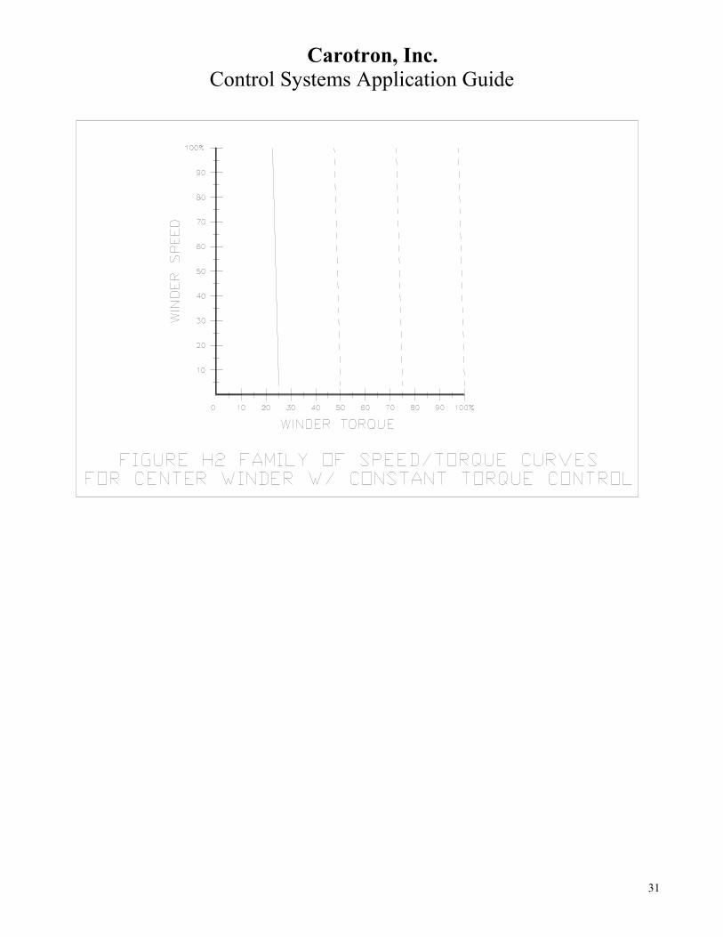
Figure H.2 shows the typical Speed/Torque Curves for a Constant Torque Control. Notice that the speed drops very rapidly
as the torque increases. This is very similar to operation of a standard velocity mode drive when the motor current/torque
level exceeds the “current limit” setpoint. The dashed lines indicate a family of curves produced with increased Torque
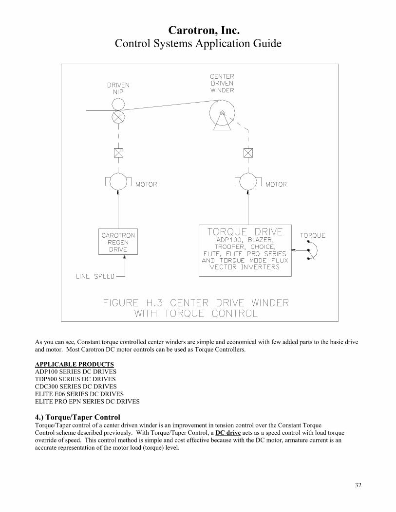
setpoints. Figure H.3 shows a typical machine diagram for a Center Driven Winder with Constant Torque Control.
Carotron, Inc.
Control Systems Application Guide
31
Carotron, Inc.
Control Systems Application Guide
32
As you can see, Constant torque controlled center winders are simple and economical with few added parts to the basic drive
and motor. Most Carotron DC motor controls can be used as Torque Controllers.
APPLICABLE PRODUCTS ADP100 SERIES DC DRIVES
TDP500 SERIES DC DRIVES
CDC300 SERIES DC DRIVES
ELITE E06 SERIES DC DRIVES
ELITE PRO EPN SERIES DC DRIVES
4.) Torque/Taper Control Torque/Taper control of a center driven winder is an improvement in tension control over the Constant Torque
Control scheme described previously. With Torque/Taper Control, a DC drive acts as a speed control with load torque
override of speed. This control method is simple and cost effective because with the DC motor, armature current is an
accurate representation of the motor load (torque) level.

Carotron, Inc.
Control Systems Application Guide
33
Refer to Figure H.4. Here we show the “ideal Constant Tension” hyperbolic shaped speed versus torque curve and a family
of curves for a Torque/Taper controlled center winder. Notice that the Torque/Taper curve, though fairly straight, closely
approximates the first portion (to about 2.5:1 build range) of the constant tension curve. So, for limited diameter change
torque mode center winders, this control method can give fairly constant tension and then taper tension beyond the 2.5:1
range. This is suitable for many limited range winder applications.
Motor maximum speed is adjusted for unloaded core maximum surface speed. This setting should exceed maximum material
feed speed by several percent to assure tension is developed and acts as the motor RPM limit in the event of web breakage.
Then a TORQUE adjustment sets a motor torque loading level at which the increasing torque feedback (armature current)
will start subtracting from the speed reference. This is indicated by the turn-on of an LED. Continuing armature current
increase as roll diameter increases will cause a further decrease in speed. The TAPER potentiometer is essentially a gain
setting that controls the slope or rate of speed decrease versus load/diameter increase. Typically, the TORQUE is set for core
tension and the taper adjustment is set for the full package tension.
With the TAPER set to minimum, full CCW rotation, drive operation is very much like a conventional speed control where
when the load torque (current) reaches and begins to pass the CURRENT LIMIT setpoint, speed falls off very sharply to a
stall level. Increasing the TAPER setting allows speed to be swapped for torque as described above – current can increase
but, only at decreased speed.
Care should be used in sizing the motor and drive so that a balance is achieved in that:
1. The motor and drive are not overloaded for long periods and

Carotron, Inc.
Control Systems Application Guide
34
2. The motor and drive are not oversized so best torque control resolution is given. The key fact here is that this control
method depends on significant motor load change with diameter increase to provide best results.
Torque/taper can be a very economical way to get good tension control for 2:1 diameter change. In this range, tension can be
adjusted to stay very nearly constant without readjusting. Operation is still best on slow line speeds and slow accel/decel
rates so that additional torque requirements are kept to a minimum. Line reverse direction operation is also to be avoided
when Torque/Taper Control is used.
Figure H.5 shows a typical machine diagram using Torque/Taper Control. Also shown is an optional
Speed follower for the Torque/Taper Control to follow line speed. Torque/Taper is a standard feature of
The Blazer BDP400 Series and is offered as an option in the ADP100 and Trooper Series.
APPLICABLE PRODUCTS ADP100 SERIES DC DRIVES
TDP500 SERIES DC DRIVES
BDP400 SERIES DC DRIVES
5.) Torque Mode Tension Control with Diameter Compensation

Carotron, Inc.
Control Systems Application Guide
35
Improvement can be made to a Torque Control or Torque/Taper Control systems by adding Diameter compensation to adjust
winder torque as diameter increases. For constant tension in the web this means that as diameter increases, the winder
rotational torque must increase proportionately. When the diameter doubles, the torque must double. Tension in the web of a
center winder is calculated as follows:
Web tension = (Winder Torque)
(Roll Diameter /2)
The diameter compensation may come from a direct measuring device such as a Carotron Sonictrac or Sonictrac Pro,
Ultrasonic distance measuring device, as shown in Figure H.6 or a simple potentiometer connected to a rider arm touching
the surface of the roll. With the Sonictrac unit, the output is scaled to indicate an increase in diameter. For example: with a
5:1 diameter increase from a 6 inch core building to 30 inches maximum diameter, you could adjust the Sonictrac for a 5:1
signal increase from 2 VDC to 10 VDC. A trim pot on the output of the Sonictrac unit can be used to adjust tension for
winding different materials.
APPLICABLE PRODUCTS D10337-000 CONSTANT TENSION CENTER WIND (CTCW) CONTROL
CLT2000-000 CORTEX LT CONTROLLER
MM3000-CTCW MICROMANAGER CTCW CONTROL

Carotron, Inc.
Control Systems Application Guide
36
MM3000 –CRG MICROMANAGER CENTER REFERENCE GENERATOR
SMU100 SERIES ULTRASONIC SENSOR
When diameter cannot be conveniently measured, there are alternate methods for providing diameter compensation by using
calculation.
Remember the Figure H.1, Winder Speed versus Winder Torque curve? This same curve is shown again in Figure H.7 below
with winder torque replaced by winder diameter. When center winder torque is controlled and limited so that no slippage or
stretching of the web occurs, the winder motor speed will follow the curve as shown.
This characteristic allows us to take a Line (surface) speed signal and divide by the measured winder motor speed signal to
calculate the winder roll diameter and required torque. Carotron offers several products that perform this calculation of
diameter. Some include a “memory” to retain the calculated diameter level when the line is stopped. This allows desired
tension to be maintained at “stop” and can help when rapidly accelerating partially “built” rolls.
APPLICABLE PRODUCTS
D10337-000 CONSTANT TENSION CENTER WIND (CTCW) CONTROL
CLT2000-000 CORTEX LT CONTROLLER
MM3000-CTCW MICROMANAGER CTCW CONTROL
MM3000 –CRG MICROMANAGER CENTER REFERENCE GENERATOR
D11005-000 MULTIPLIER/DIVIDER CARD

Carotron, Inc.
Control Systems Application Guide
37
Two other diameter calculation methods are available from Carotron and require knowledge of the thickness of the material
being wound and use an encoder or pulse generator and a counting function.
The first, roll revolutions, method counts encoder pulses to measure each revolution or rotation of the take-up roll. Each
revolution adds two material thicknesses to the diameter.
The second, line revolutions, method counts revolutions of a material driving roll (or a roll being driven by the material).
When starting with a known diameter core and a measurement of the material yardage from the line revolutions count, a
“spiral” calculation will give the take-up roll diameter.
Though a great improvement over Constant Torque or Torque/Taper control, diameter compensation alone still has
deficiencies in supplying acceleration and static and running friction compensating torque. Care should be taken in applying
its use to slower speed and slow accelerating processes.
APPLICABLE PRODUCTS
CLT2000-000 CORTEX LT CONTROLLER
MM3000-CTCW MICROMANAGER CTCW CONTROL
MM3000 –CRG MICROMANAGER CENTER REFERENCE GENERATOR
6.) Torque Mode Constant Tension Center Winder (CTCW) Constant Tension Center Wind (CTCW) Control is one of the most cost effective ways to accomplish torque mode tension
control in a center driven winder application. A primary benefit results from “open loop” control, i.e. no tension feedback
devices or mechanisms such as load cells or dancers are required. As shown in Fig. H.8, Carotron’s CTCW Controls provide
a complete reference to a torque mode drive to regulate web tension. The following signal components are available as part
of the total torque reference:
Diameter based torque, from an external source or by calculation provides the torque reference required to maintain
constant tension as the roll package builds to maximum diameter. When calculating diameter using winder motor speed, a

Carotron, Inc.
Control Systems Application Guide
38
memory circuit can hold the diameter information until reset so that stopping and restarting a partially built roll is possible
with limited tension disturbances.
A WK –Square, inertia compensation, circuit boosts winder torque during line acceleration to help keep web tension
constant.
Static and Dynamic friction compensation circuits account for friction in the winder mechanism during stalled operation,
startup and resulting from line speed increase.
Pulse torque can provide a controlled “push” to break away the mechanics of an oversized winder mechanism.
A Taper circuit can provide a tapering tension as diameter increases to lessen the chances of product damage due to roll
distortion and/or telescoping.
A Jog control circuit provides constant velocity control of the torque mode drive when threading the winder.
Figure H.7 shows the Speed/Torque characteristics that can be produced by a CTCW control scheme. The main curve shows
the characteristic required for constant tension. The chart shows the relative values for Winder Speed, Winder Torque and
Diameter of the winder roll. The dashed line shows the torque decrease given by a Taper Tension profile.
APPLICABLE PRODUCTS
D10337-000 CONSTANT TENSION CENTER WIND (CTCW) CONTROL
CLT2000-000 CORTEX LT CONTROLLER
MM3000-CTCW MICROMANAGER CTCW CONTROL
ELITE PRO DC DRIVE SERIES
7.) Torque/Velocity Mode Turret Winders Refer to Figure H.9. Here we are illustrating a dual winder arrangement where two individual winders are mounted on a
rotating turret mechanism. This arrangement mechanically enables a continuously fed web to be transferred from a full roll
on one winder to an empty core on another without stopping the web and without large changes in tension. This “transfer-on-
the-fly process” is known as making a “flying transfer” or “flying splice” when occurring on the unwind end of the line.

Carotron, Inc.
Control Systems Application Guide
39
A major difficulty with the transfer process relates to the instantaneous speed difference of the two winders due to their
difference in roll diameter at the time the material transfer is made. Use of a single drive and motor for both winders is
possible but very difficult and requires a web storage mechanism that will accumulate excess web while the motor accelerates
from “full roll” speed to “empty core” speed. For example, a 10:1 diameter change or “build range” means for a constant line
speed, the winder motor RPM at core diameter will be 10 times faster than full roll motor speed.
Better results are seen by independently controlling separate winders - each with its own motor, drive and control circuit.
This gives a “Head-Start” in response by pre-starting the new core and setting its speed a few percent faster than the line.
Then when material is transferred, the core is pulled down to line speed by the web. Winder torque loading would normally
increase with the diameter increase but is Tension regulated by the torque reference profile provided by a CTCW (Constant
tension Center Wind) type control circuit.
The key to the scheme described above is control of the speed and torque of each winder. Speed control is initially utilized
to set the core speed several percent faster than line speed. Encoders could be used for line speed and winder motor speed
sensing instead of tachometers. Torque control is then used to provide open loop tension control as diameter increases.
Carotron offers both AC Vector type inverters and DC drives that include the ability to control torque while limiting or
regulating speed.
APPLICABLE PRODUCTS
CLT2000-000 CORTEX LT CONTROLLER
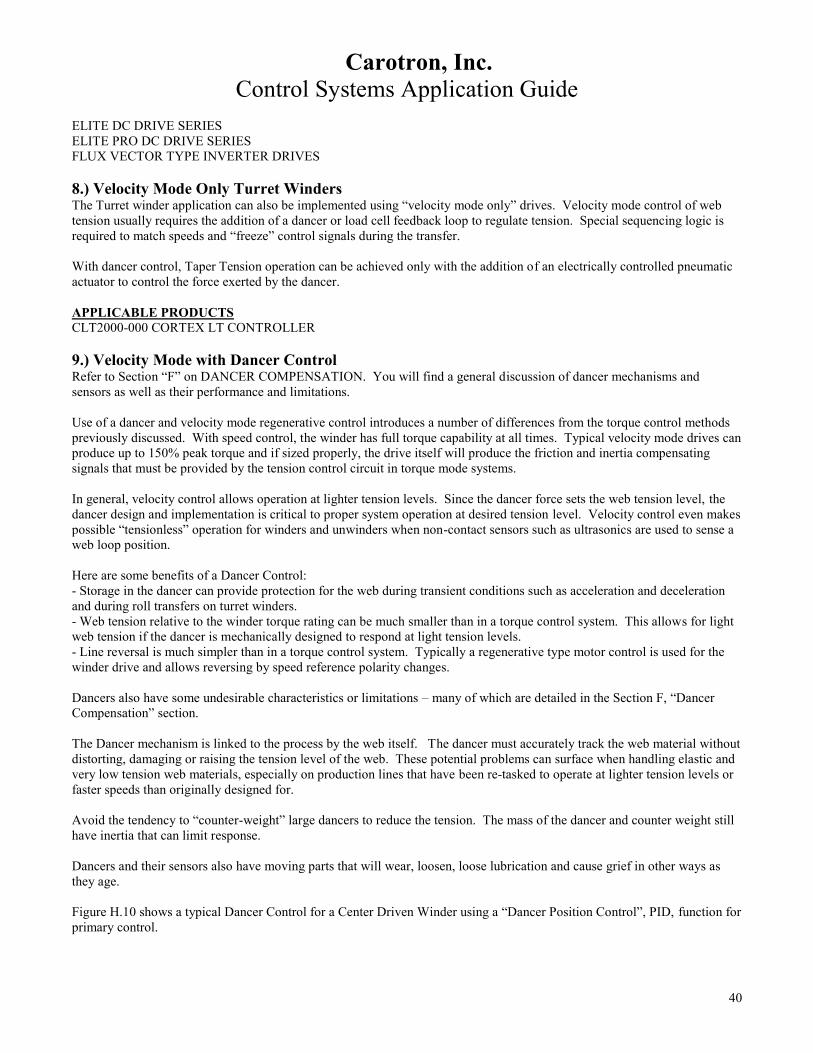
Carotron, Inc.
Control Systems Application Guide
40
ELITE DC DRIVE SERIES
ELITE PRO DC DRIVE SERIES
FLUX VECTOR TYPE INVERTER DRIVES
8.) Velocity Mode Only Turret Winders The Turret winder application can also be implemented using “velocity mode only” drives. Velocity mode control of web
tension usually requires the addition of a dancer or load cell feedback loop to regulate tension. Special sequencing logic is
required to match speeds and “freeze” control signals during the transfer.
With dancer control, Taper Tension operation can be achieved only with the addition of an electrically controlled pneumatic
actuator to control the force exerted by the dancer.
APPLICABLE PRODUCTS
CLT2000-000 CORTEX LT CONTROLLER
9.) Velocity Mode with Dancer Control Refer to Section “F” on DANCER COMPENSATION. You will find a general discussion of dancer mechanisms and
sensors as well as their performance and limitations.
Use of a dancer and velocity mode regenerative control introduces a number of differences from the torque control methods
previously discussed. With speed control, the winder has full torque capability at all times. Typical velocity mode drives can
produce up to 150% peak torque and if sized properly, the drive itself will produce the friction and inertia compensating
signals that must be provided by the tension control circuit in torque mode systems.
In general, velocity control allows operation at lighter tension levels. Since the dancer force sets the web tension level, the
dancer design and implementation is critical to proper system operation at desired tension level. Velocity control even makes
possible “tensionless” operation for winders and unwinders when non-contact sensors such as ultrasonics are used to sense a
web loop position.
Here are some benefits of a Dancer Control:
- Storage in the dancer can provide protection for the web during transient conditions such as acceleration and deceleration
and during roll transfers on turret winders.
- Web tension relative to the winder torque rating can be much smaller than in a torque control system. This allows for light
web tension if the dancer is mechanically designed to respond at light tension levels.
- Line reversal is much simpler than in a torque control system. Typically a regenerative type motor control is used for the
winder drive and allows reversing by speed reference polarity changes.
Dancers also have some undesirable characteristics or limitations – many of which are detailed in the Section F, “Dancer
Compensation” section.
The Dancer mechanism is linked to the process by the web itself. The dancer must accurately track the web material without
distorting, damaging or raising the tension level of the web. These potential problems can surface when handling elastic and
very low tension web materials, especially on production lines that have been re-tasked to operate at lighter tension levels or
faster speeds than originally designed for.
Avoid the tendency to “counter-weight” large dancers to reduce the tension. The mass of the dancer and counter weight still
have inertia that can limit response.
Dancers and their sensors also have moving parts that will wear, loosen, loose lubrication and cause grief in other ways as
they age.
Figure H.10 shows a typical Dancer Control for a Center Driven Winder using a “Dancer Position Control”, PID, function for
primary control.

Carotron, Inc.
Control Systems Application Guide
41
The dancer is shown loaded by an air cylinder to set tension. Tach feedback is shown for the winder drive to give best
response and regulation. A Scale Input utilizing a line speed signal can sensitize the dancer circuit for Line Speed changes.
Refer to Section F, Dancer Compensation, for a more complete explanation of this benefit. An alternate Scale Input signal
for large diameter changes would be to use a Sonictrac unit to monitor roll diameter and scale the dancer control circuit
according to roll size.
APPLICABLE PRODUCTS
D10541-000 DANCER POSITION CARD
CLT2000-000 CORTEX LT CONTROLLER
MM3000-PID MICROMANAGER CONTROLLER
10.) Velocity Mode with Divider Control Velocity Control of a center driven winder or unwinder using Carotron’s Divider function circuitry has proven to be a very
effective control method. This function is especially useful in applications with large build (diameter change) ratios.
Several methods are available for measuring diameter. Refer to section J.1 and Figure H.7 for discussion on using ultrasonics
for diameter sensing and on the relationship between center wind diameter and rotational speed. This Figure illustrates how
center drive motor speed can be used to calculate diameter for torque winding applications and how measured diameter can
be used to calculate the center drive motor speed to give constant surface speed.
Another measuring method would use a “rider” pivot arm device that rests on the surface of the roll and has a potentiometer
connected at the pivot point to rotate and increase signal as the arm is lifted by the increasing diameter of the roll. Non-
contact methods would use ultrasonic sensing or laser sensing to provide the increasing diameter signal. With these methods
logic must be included to translate measured “distance” that decreases with diameter increase to an increasing diameter
signal. This translation capacity is standard within Carotron ultrasonic sensing products.

Carotron, Inc.
Control Systems Application Guide
42
Figure H.11 shows a typical center wind application using a Divider function circuit. The motor drive is operated in a
velocity mode so that the winder has full torque capacity at all times - if sized properly. Key additions in this control scheme
are the Divider function circuit and a roll diameter measurement or calculation means.
A dancer is still used to set the web tension and to provide a + “percentage” trim to the output of the Divider function card.
A further performance improvement can be achieved by including a “Dancer Position – PID” function instead of the dancer
trim function to give improved dancer position accuracy and tension control.
APPLICABLE PRODUCTS
D10541-000 DANCER POSITION CONTROL CARD
D11005-000 MULTIPLIER/DIVIDER FUNCTION CARD
CLT2000-000 CORTEX LT CONTROLLER
MM3000-PID MICROMANAGER CONTROLLER
SMU100-XXX SONICTRAC, ULTRASONIC MEASURING UNIT
STP200-000 SONITRAC PRO, ULTRASONIC MEASURING UNIT

Carotron, Inc.
Control Systems Application Guide
43
Figure H.12 illustrates an application where there is no “surface driving roll” or process to set and control “line speed”. The
winder itself controls the web speed. With no diameter compensation, web speed will increase with diameter increase. Use
of diameter sensing and the “divider” function circuit will give a constant take-up speed with diameter controlled braking
force used to control web tension. This control scheme could be switched around where the “Unwind” is speed controlled
with a regenerative drive and the winder is torque controlled.
APPLICABLE PRODUCTS
D11005-000 MULTIPLIER/DIVIDER FUNCTION CARD
CLT2000-000 CORTEX LT CONTROLLER
MM3000-CRG MICROMANAGER CONTROLLER
SMU100-XXX SONICTRAC, ULTRASONIC MEASURING UNIT
STP200-000 SONITRAC PRO, ULTRASONIC MEASURING UNIT
11.) Velocity Mode with Tension Transducer (Load Cell) Control Load Cell tension transducer control is probably the most expensive approach to tension control in web processing. Load
cells provide a means to directly sense the web tension and control either winder speed or torque. Implemented much like
dancer controlled system, tension transducer feedback can give very accurate control and permit display of tension but,
without some of the benefits of a dancer.
Figure H.13 shows a representative method for using a load cell in a center driven winder application. The low level output
of the load cell(s) can be isolated and amplified by Carotron’s Model D10562-000 Precision Bipolar Isolation Card. The
amplified signal can then be compared to a Tension setpoint within a PID function to trim the center winder speed signal that
is calculated using the diameter signal and the Divider function.

Carotron, Inc.
Control Systems Application Guide
44
At Carotron, we refer to load cells as “zero accumulation dancers”. Obviously, no material storage is provided and range
limitation of the “tension control loop” is even more critical than with dancers. This places greater responsibility for control
with other control functions such as diameter sensing and center drive speed calculation. Carotron does not recommend
100% control of center driven rolls by tension transducer loop alone.
With tension transducers, the physical mounting, web wrap angle, device sizing, machine vibration, and sensor roll balancing
are some of the factors that greatly influence the accuracy and stability of the transducer(s) as a sensing device. Electrical
noise can also be a major concern since some tension transducers, strain gauge types, only produce a few millivolts with full
rated force applied. They usually require interface to the control circuit via a signal conditioning circuit that can provide
excitation, amplification and isolation.
Caution should be taken to address each of these concerns, especially for a center wind application since tension loop control
range must accommodate the “line speed turn-down range” and roll build range.
APPLICABLE PRODUCTS
D11005-000 MULTIPLIER/DIVIDER FUNCTION CARD
CLT2000-000 CORTEX LT CONTROLLER
MM3000-CRG MICROMANAGER CONTROLLER
SMU100-XXX SONICTRAC, ULTRASONIC MEASURING UNIT
STP200-000 SONITRAC PRO, ULTRASONIC MEASURING UNIT
D10562-000 PRECISION BIPOLAR ISOLATION CARD
12.) Constant Horsepower Winders Most “Inverter Duty” and some specially rated DC motors have speed capabilities above the rated base speed specification.
This type of operation above base speed is called “Constant Horsepower” operation where motor torque capability is
swapped for additional speed capability. Several applications including center driven winders, spindle drives and carbide
cutoff saws utilize constant horsepower operation.

Carotron, Inc.
Control Systems Application Guide
45
With constant horsepower operation, the drives are operating as velocity regulators and when used on a center winder
application still require one of the Velocity Mode logic and control schemes previously described. The primary benefit is
that the motor and drive horsepower rating (and associated costs) can be much lower than when using a conventional ~1750
RPM base speed motor.
A.) Constant HP DC Drive Operation
Use of a Field Current Regulator to supply the DC motor shunt field current allows the motor field current to be reduced
above base speed to give the higher speed capability. The DC Motor control will operate in armature voltage control up close
to base speed at which time the field regulator will control from base speed to the extended speed by reducing the field
current. This control method is sometimes referred to as “field crossover” or “field weakening” control. Refer to Figure
H.14.
An important aspect of this control method relates to the fact that the actual armature voltage level is used to control the field
current level. To give full torque capability over most of the base speed range, the field current reduction is usually held off
until armature voltage is greater than 90%. For a 4:1 speed increase by field weakening, about 25% motor speed is reached at
90% armature voltage. The last 75% of the speed range is then achieved with the final ~ 10% armature voltage increase or
within the last 10% of a speed pot adjustment range if the drive was operated in “armature feedback”. For this reason,
tachometer or encoder feedback is always used to keep the speed range linear with respect to the speed reference.
Carotron products include a Field Regulator control series that can control motor fields rated up to 35 amperes. This unit can
be used with any brand of DC drive to give the constant horsepower operation. Carotron’s Elite Pro drive series has the field
regulator “built in” for easier setup and control up to 700 horsepower.
It is important to remember that when a DC Motor is operated above base speed, significant torque capability is lost. A DC
Motor will operate at constant full rated torque up to base speed. Above base speed, the motor must be operated in constant
horsepower mode.
Figure H.15 shows an example of a DC Motor rated at a base speed of 1750 RPM with an extended range of 2300 RPM. A
base speed rating of 500 RPM with maximum extended speed of 3000 RPM is possible in some motor designs. Such wide
speed range motors are built in larger frame sizes since for a given horsepower rating at a lower base speed, the
corresponding torque capacity is much higher.
Carotron, Inc.
Control Systems Application Guide
46
B.) Constant HP AC Drive Operation
With AC Inverter drives and motors, extended speed operation is achieved with different methods but, the results are pretty
much the same as with DC controls and motors. Normally, inverters supply an output voltage to the motor that is applied in
level and frequency in a “constant volts-per-Hertz” ratio. This means that a motor rated at 460 VAC, 60 Hz maximum for
rated base speed would require 230 VAC at 30 Hz at ½ speed or 46 VAC at 6 Hz at 1/10 speed. Full rated motor torque is
available over this range.
To achieve a “constant horsepower” extension of speed, the inverter can be programmed to continue increasing the frequency
of the output above 60 Hz while holding the voltage at the rated maximum. Just as with DC drives and motors, the available
torque must be de-rated. Some inverters have an output frequency range up to 400 Hz to give over a 6:1 speed increase. This
can usually be done with a standard inverter duty motor – the primary limit is that inverter and /or motor full load current
should not be exceeded. Therefore the application load characteristic must adhere to the “constant horsepower” profile where
the motor load does not increase with speed.
APPLICABLE PRODUCTS
FR1000-000 AND FR3500-000 FIELD REGULATOR CONTROLS
ELITE PRO DIGITAL DC DRIVE SERIES
AC INVERTER CONTROLS – CONSULT FACTORY FOR AVAILABLE MODELS
I. Zone Tension Control A “tension controlled zone” can exist between any two adjacent and controlled rolls in a web transporting system.
“Controlled” means having motoring or braking force regulated by a brake, clutch or drive and motor. The web must be
positively gripped by these rolls so that the applied force is completely and evenly imparted as desired tension.

Carotron, Inc.
Control Systems Application Guide
47
All of the Multiple Drive systems and Center Drive control systems we’ve already discussed meet these criteria. Those
velocity controlled drive systems with no active tension controlling or feedback device such as a dancer or load cell must rely
on web compliance and operator attention to Speed Trimming for acceptable operation.
The various Torque control methods provide “open loop” tension control by virtue of internal signal processing within the
drives. The addition of “special function devices for diameter sensing or smart circuits for calculating diameter and other
required torque signals for complete CTCW control gives respectable performance in many applications – without the
addition of active feedback devices.
Then, velocity mode center driven winder and unwinders with active feedback from dancers and load cells use sophisticated
signal processing to compensate for diameter change and transient operating conditions such as speed change, load change
and tension command change.
In some cases an isolated zone of lower or higher than normal tension must be established for special web processing such as
drying with overfeed, coating, sizing, slitting, punching, etc. With the exception of diameter compensation when not
applicable, all of the described control methods can be used for Zone Tension control for surface driving and/or braking rolls.
Some examples are shown in Figures I.1 and I.2.
Figure I.1 illustrates “closed loop” zone tension control with dancer feedback. As in all dancer feedback systems, the tension
is controlled by the force exerted by the dancer or compensator arm. Since the dancer pot here is used as a trimming device,
transient errors in tension may cause a shift in dancer position until a balancing speed correction is produced.

Carotron, Inc.
Control Systems Application Guide
48
Figure I.2 shows zone tension control using load cell feedback. Here the “exit” drive follows the “entry” speed with greater
tension accuracy maintained through the use of a PID function circuit providing a + percentage speed correction.
In both of these examples, proper gearing of the exit roll is important. It must be geared to “greater than line speed” to give
“catch-up” capability when operating at maximum line speed. Again, in both examples, the range of the tension correcting
dancer or load cell circuit should be minimized to only that level required for proper control.
APPLICABLE PRODUCTS
CLT2000-000 CORTEX LT CONTROLLER
MM3000-PID MICROMANAGER
D10541-000 DANCER POSITION (PID) CONTROL
C10209-000 ISOLATION CARD
C10032-000 SIGNAL FOLLOWER CARD
D10562-000 PRECISION BIPOLAR ISOLATION CARD
J. “Non-Contact” Loop Control We’ve encountered a number of applications in which customers want to transport or handle a material web while making
minimal contact with it. These webs still must pass through various processes and operations that require zone tension
control. Where these processes might traditionally be separated by a load cell or dancer controlled loop of material, we have

Carotron, Inc.
Control Systems Application Guide
49
to use alternate methods for non-contact sensing. One popular non-contact sensing method utilizes ultrasonic distance
measurement.
1.) Ultrasonic Loop Control There are a number of “conditions of use” that affect the success of ultrasonic sensing.
A.) TARGET DENSITY:
Since ultrasonics work much like a bat in transmitting an ultrasonic sound and waiting for a reflected echo, the
density of the target material affects how much sound signal is reflected. Traditional sound dampening or
suppressing materials work by dispersing the echo instead of reflecting it back directly to the source. Open cell
foam is a good example of this. Some very sheer fabrics and materials like cotton batting lack the density to
disperse or reflect much echo – the sound passes through them.
B.) TARGET DISTANCE:
The amplitude of a sound echo attenuates greatly with distance. A target at a near distance is more likely to be
detected than the same target further away – especially with low density materials such as mentioned above. When
you have a choice, mount the sensor as close to the target as practical while maintaining any required minimum
distance.
C.) TARGET SIZE, SHAPE & ORIENTATION
Ultrasonic distance measurement depends on processing the round trip travel time of a transmitted sound and its
echo return from the target. Since the transmitted sound is emitted in a direction perpendicular from the face of the
transducer, some portion of the target must be perpendicular to the emitted sound (or parallel to the transducer face)
for the echo to return to the transducer.
In actuality, the transmitted signal is emitted in a cone shape with about 12 degrees beam spread. Greater distance
from the transducer then means a larger diameter “detection cone”. At 5 feet, the cone diameter is between 12 and
18 inches diameter. At 10 feet the diameter is between 24 and 36 inches. This means a target doesn’t have to be
directly in front of the transducer to be detected but, this also means that undesirable targets at the cone perimeter
may be detected. An ideal target shape would be a parabolic or dish shape which would focus the echo back at the
transducer.
When sensing a loop of web material, several things should be considered:
1. The sensor should be positioned directly above the “valley’ or lowest and flattest part of the loop to
assure the reflection of an echo back to the sensor.
2. When viewing across the width of a loop or the length of a roll, the surface should lie flat – again to
create a perpendicular surface to assure the reflection of an echo back to the sensor.
3. Use care in positioning the sensor if one side of the loop is supported by a “center driven” roll. As the
diameter of this roll changes, this side and the valley position of the loop will shift. The sensor can
usually be pointed toward the center of the movement range to provide satisfactory operation.
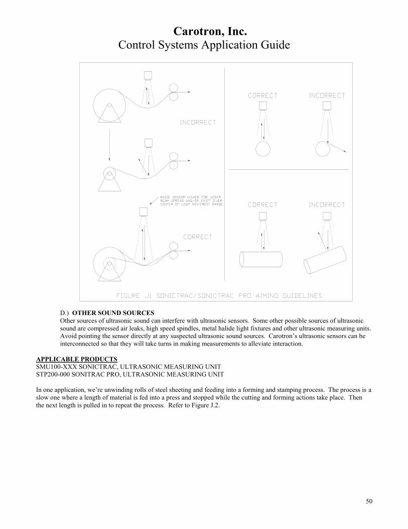
Carotron, Inc.
Control Systems Application Guide
50
D.) OTHER SOUND SOURCES
Other sources of ultrasonic sound can interfere with ultrasonic sensors. Some other possible sources of ultrasonic
sound are compressed air leaks, high speed spindles, metal halide light fixtures and other ultrasonic measuring units.
Avoid pointing the sensor directly at any suspected ultrasonic sound sources. Carotron’s ultrasonic sensors can be
interconnected so that they will take turns in making measurements to alleviate interaction.
APPLICABLE PRODUCTS
SMU100-XXX SONICTRAC, ULTRASONIC MEASURING UNIT
STP200-000 SONITRAC PRO, ULTRASONIC MEASURING UNIT
In one application, we’re unwinding rolls of steel sheeting and feeding into a forming and stamping process. The process is a
slow one where a length of material is fed into a press and stopped while the cutting and forming actions take place. Then
the next length is pulled in to repeat the process. Refer to Figure J.2.

Carotron, Inc.
Control Systems Application Guide
51
The low speed of this application allows simple and direct control of a material loop by an ultrasonic sensor. The ultrasonic
sensor is set up to provide a + DC reference signal to a regenerative drive whose output direction is controlled by the
reference polarity. The regenerative capability is also required to handle the high inertia of the material roll.
The loop sensor outputs zero volts at the desired loop null or parking position. When the nip rolls ahead of the stamping
section starts pulling material, the loop is lifted. The sensor will output a positive reference proportional to the loop distance
- a higher loop closer to the sensor produces higher output. This causes the unwinder to motor forward - paying out material
until the loop drops to the null position. If the loop were to drop below the null position, the sensor will produce a
proportionally increasing negative signal that will tell the unwinder to run reverse until loop null position is again reached.
APPLICABLE PRODUCTS
SMU100-XXX SONICTRAC, ULTRASONIC MEASURING UNIT
STP200-000 SONITRAC PRO, ULTRASONIC MEASURING UNIT
2.) Optical or Proximity Detection Loop Control Other non-contact sensors are available for materials where ultrasonic detection is not appropriate. The following control
scheme utilizes sensors that simply detect the presence or absence of material in a loop control application. Capacitive
proximity sensors or photo-electric sensors – whatever is appropriate for the web material can be used. The control is
operating a drive on the input of the loop – increased speed will lower the loop and decreased speed will raise it.

Carotron, Inc.
Control Systems Application Guide
52
A Carotron MOP (electronic Motor Operated Pot) function is controlled by loop “upper” and “lower” position sensors. A
contact closure from each sensor is used to operate the “increase” or “decrease” inputs of the MOP. The upper sensor contact
closes when not sensing the loop material. This operates the “increase” input which increases motor speed until the loop
again falls in front of the sensor. Presence of the loop in front of the lower sensor operates the “decrease” input to slow the
drive and raise the loop. When either contact is opened, the output voltage freezes at its present level. The rate of output
signal change is controlled by acceleration and deceleration adjustments.
The ability of the electronic MOP circuit to source its output from an external signal, such as the line speed reference, enables
the trim function to be speed proportional. The acceleration adjustment in the circuit allows the rate of the correction to be
optimized for the loop size and desired response.
APPLICABLE PRODUCTS
D10341-000 ELECTRONIC MOP (MOTOR OPERATED POT)
K. Winder Traverse Drive The need often occurs in product winding to control the pitch (spacing between each lay of web) on a traversed winder. This
is especially important with narrow webs such as wire and fiber to prevent the web form over-lapping itself, making it very
difficult to unwind for the following process. In these cases the pitch may be quite wide.
Because many of the winders of this type are center driven, the pitch must be adjustable and corrected for the change in speed
of the winder as its driven core is slowed to compensate for roll build up.
The following diagram Figure K.1 shows a common scheme for this application.

Carotron, Inc.
Control Systems Application Guide
53
The traverse motor is connected to the traverse mechanism and is cycled by travel limits. Use of a DC regenerative drive
allows reversing by switching the polarity of the reference command. The reference is developed by a voltage or frequency
follower circuit, slaving the adjusted pitch to the winder speed by means of a motor mounted tach or encoder on the winder
motor.
APPLICABLE PRODUCTS
C10032-000 SIGNAL FOLLOWER CARD
C10209-000 ISOLATION CARD
D10562-000 PRECISION BIPOLAR ISOLATION CARD
C10330-000 FREQUENCY TO VOLTAGE CONVERTER
C11451-000 PRECISION FREQUENCY TO VOLTAGE CONVERTER
L. Load Regulated Feeder Control Feed belts and conveyers which deliver product to crushers, grinders, shredders and similar processes are excellent
candidates for load regulation of the feed rate to prevent “choking” or overloading of the process. The crusher device is
typically driven by an AC induction motor. The load current of this motor will change in proportion to the volume of
material delivered. In order to maintain the optimum crushing consistency and prevent jam-ups or overloads, the feed rate
must be controlled based on the loading of the motor.
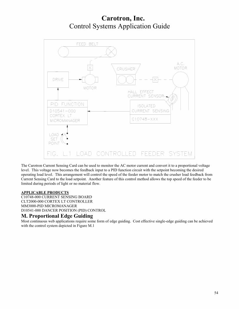
Carotron, Inc.
Control Systems Application Guide
54
The Carotron Current Sensing Card can be used to monitor the AC motor current and convert it to a proportional voltage
level. This voltage now becomes the feedback input to a PID function circuit with the setpoint becoming the desired
operating load level. This arrangement will control the speed of the feeder motor to match the crusher load feedback from
Current Sensing Card to the load setpoint. Another feature of this control method allows the top speed of the feeder to be
limited during periods of light or no material flow.
APPLICABLE PRODUCTS
C10748-000 CURRENT SENSING BOARD
CLT2000-000 CORTEX LT CONTROLLER
MM3000-PID MICROMANAGER
D10541-000 DANCER POSITION (PID) CONTROL
M. Proportional Edge Guiding Most continuous web applications require some form of edge guiding. Cost effective single-edge guiding can be achieved
with the control system depicted in Figure M.1

Carotron, Inc.
Control Systems Application Guide
55
This system must be used in conjunction with a rotary input linear actuator usually driven by a fractional horsepower motor
and regenerative drive. A proportional output photo-electric sensor and reflector provide an isolated output from 0 to 5 VDC
based on percent of reflection. There are several manufacturers of such sensors.
The photo-electric sensor is adjusted to give 2.5 VDC output when blocked 50% by the material edge.
This signal is processed by the EG1000-000 control to drive a motor forward or reverse (left and right actuator operation) at a
speed proportional to the position error – greater error gives higher correction speed. This proportioning feature of the
correction provides a very smooth and effective guiding action when compared to other “on-off” types of guiding often used.
This low cost regenerative control method bridges the gap between the lower performance non-proportional control systems
and the higher performance servo driven systems costing much more.
APPLICABLE PRODUCTS
EG1000-000 PROPORTIONAL EDGE GUIDER CONTROL
N. Ramp to Stop using Zero Speed Detector
Many applications require a drive system that has a controlled stop feature. Controlled stopping allows multiple drives and
motors in a system to decelerate in coordination so that zone tension levels are maintained. Carotron’s model C10334-000
Zero Speed Relay card provides a universal voltage sensitive relay circuit for use in “ramp to stop” logic for DC Motor
Control systems. Armature voltage ranges of 90, 180, 240 or 500 VDC may be sensed for logic control. A voltage input of
any polarity is acceptable.
When the 90/180 VDC input range is used, the zero speed relay de-energizes at approximately 5 VDC from the armature
output of the system “lead” drive. For the 240/500 VDC input range, the switching level is approximately 10 VDC. Four
form-c contacts are available for customer use. When connected as shown in Figure N.1, pressing the STOP button will
cause the lead and system drives to decelerate to zero speed at which the drives will then be stopped.
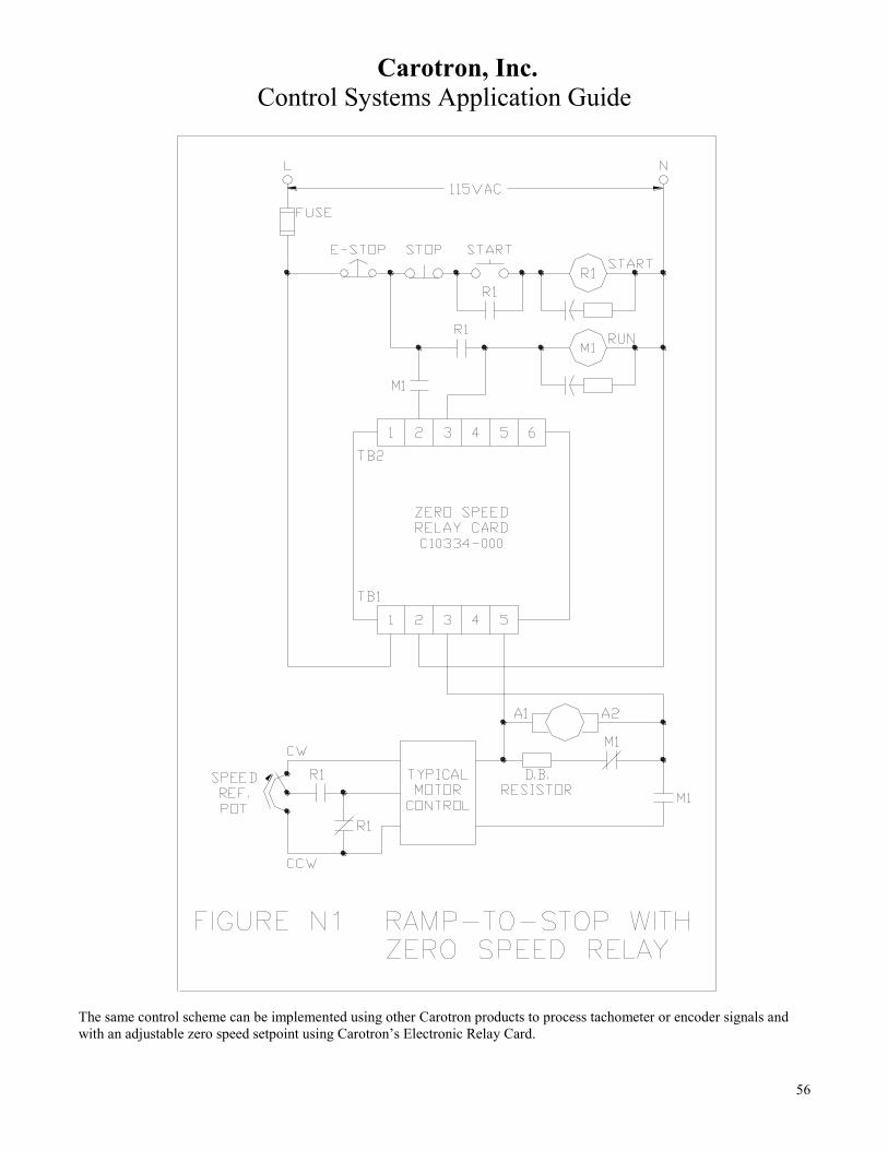
Carotron, Inc.
Control Systems Application Guide
56
The same control scheme can be implemented using other Carotron products to process tachometer or encoder signals and
with an adjustable zero speed setpoint using Carotron’s Electronic Relay Card.
Carotron, Inc.
Control Systems Application Guide
57
APPLICABLE PRODUCTS
C10334-000 ZERO SPEED RELAY CARD
C10472-000 ELECTRONIC RELAY CARD
O. Line Reactors & Drive Isolation Transformers Adjustable speed drives, both AC inverters and DC drive types; convert the AC line voltage to DC by rectification using
diode bridge or SCR rectifiers. With DC drives, the converter output is connected directly to the motors and with inverters it
is fed to a DC bus and inverter power section. The current created by the rectifiers is non-sinusoidal or “nonlinear” and can
cause the power system voltage to become distorted. This harmonic voltage distortion can have adverse effects on other
equipment connected to the same power system.
In addition, when three phase input 6-pulse rectification by SCRs is used on DC drives and on some inverters, there are six
times per power line cycle when current is transferred from one phase to another and a transient “short circuit” occurs. The
associated peak in current can cause “notching” in the voltage waveform which other equipment may not tolerate and may
cause damaging resonant currents in the electrical system.
AC inverters and their motors create a unique situation related to the high frequency switching of transistors in the drive’s
PWM (pulse width modulated) output section. The fast rise and fall times (high dvdt) of the applied voltage during each
cycle can generate very high voltages on wiring to the motor and within the motor windings between phases and to ground.
The problem is more pronounced with long wire runs (> 25 feet) to the motor; transient voltage levels can approach
thousands of volts. This particular phenomenon is the primary reason for the development of “inverter duty motors” and
inverter rated motor lead wire.
Finally, with inverters we sometimes see the effects of the high frequency PWM oscillators and switching of transistors in the
form of high frequency radiated and conducted noise. With some inverters, the RFI (radio frequency interference) noise has
been known to affect other circuitry even when the inverter is just powered and not operating the motor.
1.) LINE REACTORS with INVERTERS
A line reactor is a linear current-limiting inductor that is connected in series with each AC line input to a variable speed drive.
Packaged as a three phase input assembly, these units do not provide isolation from the AC line. When using inverter
drives, reactors can also be used between the drive and motor.
Reactors provide a two-way benefit in that they protect other line connected equipment from ill effects generated by the
inverter and protect the inverter from the negative effects of other line connected equipment. Line input reactors are very
useful and cost effective in reducing the effects of harmonic distortion and line notching described above. They can also
protect the drive from nuisance “bus over-voltage” tripping and provide fault current limitation.
When used between the drive and motor they can filter the high transient voltages and provide motor fault current limitation.
This can extend the life of the output transistors. They will reduce motor noise and operating temperature.
With inverter drives, line reactors are typically sized according to the horsepower or KVA rating and the drive/motor
voltage rating. They’re available in different impedance ratings which relate to the full load voltage drop expressed as a
percentage of the rated voltage. Carotron recommends 5% reactors for use on the AC line inputs and 3% units when used
between the drive and motor.
2.) LINE REACTORS with DC DRIVES DC drives also realize the two way benefit of line reactors. Line voltage distortion and notching caused by the drive is
filtered from the incoming AC line supply and conversely interference imposed on the line by other devices is filtered from
the drive. The available short circuit current from the line is limited.
Sizing of line reactors for DC drives may differ somewhat from inverters because the AC line current versus horsepower can
be higher. Typically the primary ill affect of the drive is line notching and a 3% reactor is usually adequate. One sizing
method looks at the equivalent horsepower inverter reactor size and then uses the next larger size. Another method looks at
the line voltage and actual line current rating of the drive and matches to a reactor with an equivalent current rating.
3.) DRIVE ISOLATION TRANSFORMERS

Carotron, Inc.
Control Systems Application Guide
58
An obvious difference between a transformer and a line reactor is the ability to transform the voltage level of the power
system. DITs, drive isolation transformers, provide this same ability and include several differences that make them more
suitable for three phase input drive applications than conventional transformers or line reactors.
We’ve discussed adjustable speed drives and their negative affects on the AC line in the form of distorted current. The
severe cyclic nature of many drive processes also cause supply current surges that create mechanical stress in the transformer.
The current transients that cause line notching adds to the mechanical stress. DIT type transformers can supply the distorted
current loads without excess heating and are designed to deal with the mechanical stress. DITs, like reactors add reactance in
the AC line that can reduce the current and voltage distortion.
Another major difference from reactors is that the secondary of a drive isolation transformer represents a separately derived
power supply that is electrically isolated from the primary power source. If the secondary is wye connected, it can be
grounded. Grounding prevents the transfer of common-mode noise and transients, both from the primary source to the motor
drive, and from the drive to the power system.
Another benefit of a grounded wye secondary relates to the ability of motor drives to generate large induced ground currents.
This is due to rapid current changes caused by diodes, SCRs, or PWM outputs that couple currents capacitively back to the
source. High-frequency induced ground currents are a major cause of data disruption in digital communication and nuisance
tripping of ground fault systems. Introducing a grounded, drive isolation transformer localizes the ground current effect and
prevents it from extending upstream from the transformer.
P. Formulas
HORSEPOWER CALCULATIONS:
HP = TN Where: T = Torque in (lb-in)
63000 N = Base Speed (RPM)
--------------------------------------------------------------------------------------------
HP = TN Where: T = Torque in (lb-ft)
5250 N = Base Speed (RPM)
HP CALCULATIONS for CENTER DRIVEN WINDERS:
HP = TV x B/U Where: T = Web Tension (lbs)
33000 V = Line Speed (ft/min)
B/U = Build Up Ratio = full roll diameter
core diameter
ACCELERATION TORQUE CALCULATION: When a machine must be accelerated to a given speed in a certain amount of time, the drive system HP
may have to supply additional torque during acceleration to compensate for the load inertia. The
acceleration torque must be added to the normal torque requirements of the machine.
T = WK2 x ΔN Where: T = acceleration Torque (lb-ft)

Carotron, Inc.
Control Systems Application Guide
59
308t ΔN = change in speed (rpm)
t = acceleration time (seconds)
WK² = total system inertia (lb-ft2)
includes motor, reducer & load
INERTIA: Inertia is a measure of a body’s resistance to changes in velocity. The factor WK
2
(inertia) is the weight of a rotating object multiplied by the square of the radius of gyration K.
FOR A SOLID CYLINDER
T = ρ x L x D4 Where: WK
2 = inertia (lb-ft
2)
1467 ρ = density (lb-in³
L = length (in)
D = diameter (in)
------------------------------------------------------------------------------------------------
FOR A GIVEN WEIGHT
WK² = W x D2 Where: WK
2 = inertia (lb-ft
2)
8 W = weight (lbs)
D = diameter (ft)
------------------------------------------------------------------------------------------------
FOR A HOLLOW CYLINDER
WK2 or WR
2 = W x (R2
2 - R1
2 Where: WK
2 = inertia (lb-ft
2)
2 W = weight (lbs)
R2 = outer radius (ft)
R1 = inner radius (ft)
DENSITY VALUES FOR COMMON MATERIALS
MATERIAL DENSITY lbs/in3 (p)
Aluminum 0.0924
Bronze 0.3200
Cast Iron 0.2600
Nylon 0.0510
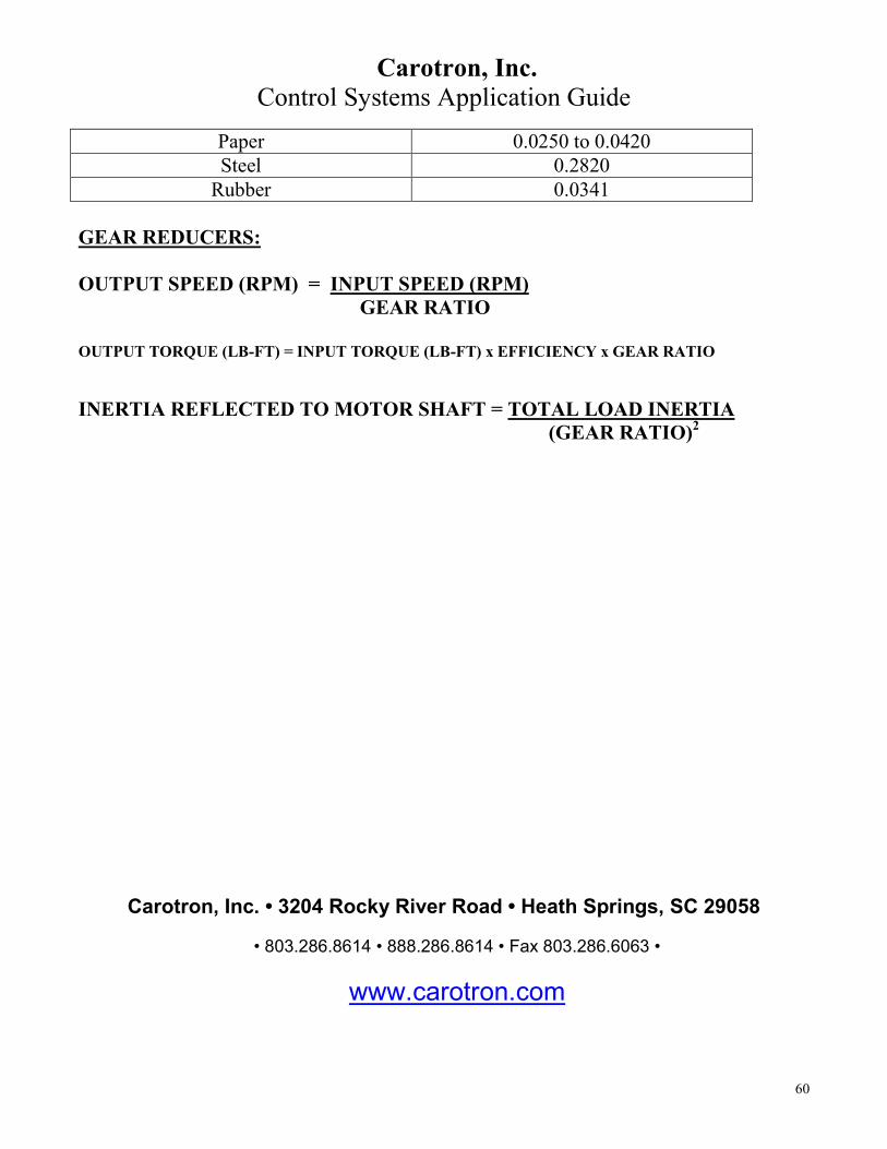
Carotron, Inc.
Control Systems Application Guide
60
Paper 0.0250 to 0.0420
Steel 0.2820
Rubber 0.0341
GEAR REDUCERS:
OUTPUT SPEED (RPM) = INPUT SPEED (RPM)
GEAR RATIO
OUTPUT TORQUE (LB-FT) = INPUT TORQUE (LB-FT) x EFFICIENCY x GEAR RATIO
INERTIA REFLECTED TO MOTOR SHAFT = TOTAL LOAD INERTIA
(GEAR RATIO)2
Carotron, Inc. • 3204 Rocky River Road • Heath Springs, SC 29058
• 803.286.8614 • 888.286.8614 • Fax 803.286.6063 •
www.carotron.com