control of low level wind sher(u air 1/2 coll apr ... · shear hazards must be part of the sifc...
TRANSCRIPT

RD-RI56 568 RECOGNITION AND CONTROL OF LOW LEVEL WIND SHER(U AIR 1/2COMAND AND STAFF COLL MAXUELL AFB AL N G ROGERSAPR 85 RCSC-85-2215
UNCLASSIFEE FG 42 H
Ehhmmomhhhhhhl
I~oo mhmhhmolhmmhmhonhhhhhhmonoh

'IL
1111Q L.0.6L11a o 112.
1111 *18J.2 J1111.4... 1111 16
MICROCOPY RESOLUTION TEST CHARTNATIONAL BUREAU OF STANOAROS-1963-A
MINN"

In
In
OF~
C.Do
luu
OF
LOW LEVE Wzd I ND SHAaD I
__ __ _ _ _ --lo 06 25 061 -
---------------.. c~_t..,

DISCLAIMER
The views and conclusions expressed in thisdocument are those of the author. They arenot intended and should not be thought torepresent official ideas, attitudes, orpolicies of any agency of the United StatesGovernment. The author has not had specialaccess to official information or ideas andhas employed only open-source materialavailable to any writer on this subject.
This document is the property of the UnitedStates Government. It is available fordistribution to the general public. A loancopy of the document may be obtained from theAir University Interlibrary Loan Service(AUL/LDEX, Maxwell AFB, Alabama, 36112) or theDefense Technical Information Center. Requestmust include the author's name and completetitle of the study.
This document may be reproduced for use inother research reports or educational pursuitscontingent upon the following stipulations:
-- Reproduction rights do not extend toany copyrighted material that may be containedin the research report.
-- All reproduced copies must ccatain thefollowing credit line: "Reprinted bypermission of the Air Command and StaffCollege."
-- All reproduced copies must contain thename(s) of the report's author(s).
-- If format modification is necessary tobetter serve the user's needs, adjustments maybe made to this report--this authorizationdoes not extend to copyrighted information ormaterial. The following statement mustaccompany the modified document: "Adaptedfrom Air Command and Staff Rs eirch Report
- , ,,- ,, ,.nu1 r iI I e d it l,, - hI t IaI U i n )
Tnis notice must be included with anyreproduced or adapted portions of thisdocument.

REPORT.. .. .. ....M... .. .. ... .. ... .. ..
RPONSR NUMBER 85-2215IOW SFC
Submitted to the faculty in partial fulfillment ofrequirements for graduation. 4
AIR COMMAND AND STAFF COLLEGE
AIR UNIVERSITY
MAXWELL AFB, AL 36112 -
This v~
distributiou 1-1 u 11'.1ittA

UN% JLASS IFIEDSECURITY CLASSIFICATION OF THIS PAGE
REPORT DOCUMENTATION PAGEi. REPORT SECURITY CLASSIFICATION 1b. RESTRICTIVE MARKINGS
UNCLASSIFIED N/A2. SURITY CLASSIFICATION AUTHORITY 3. OISTRIBUTIONI'AVAI LABILITY OF REPORT
2b. DECLASSIFICATION/DOWNGRADING SCHEDULE
4. PERFORMING ORGANIZATION REPORT NUMBER(S) 5. MONITORING ORGANIZATION REPORT NUMBER(S)
85-2215
6a, NAME OF PERFORMING ORGANIZATION 6b. OFFICE SYMBOL 7a. NAME OF MONITORING ORGANIZATION
ACSC/EDCC I______6c. ADDRESS (City. Slate and ZIP Code) 7b. ADDRESS (City. State and ZIP Code)
* Maxwell AFB, AL 36112
8o. NAME OF FUNDING/SPONSORING 8b. OFFICE SYMBOL 9. PROCUREMENT INSTRUMENT IDENTIFICATION NUMBER*ORGANIZATION (If applicable)
Sc. ADDRESS (City. State aird ZIP Code) 10. SOURCE OF FUNDING NOS.
PROGRAM PROJECT TASK WORK UNITELEMENT NO. NO. NO. NO.
11. TITLE (include Security Classification)
RECOGNITION AND CONTROL OF LOW LEVEL12. PERSONAL AUTHOR(S)
ROGERS, WILLIAMV G., MVAJOR, USAF13. TYE O REORT13b. TIME COVERED 14.. -DATE OF REPORT (Yr. Mo.. Da) 1.PAGE COUNT
FROM ____T ___ 1985 April 10715. SUPPLEMENTARY NOTATION
ITEM 11. vWIND SHEAR
17. COSATI CODES 18. SUBJECT TERMS tContinue on reverse if necessary and identify by block number)
FIELD GROUP SUB. GR.
19. ABSTRACT (Continue on reverse if necessary and iden tify by block number)
This is a two hour lesson plan/handbook and slide presentation onlow level wind shear. The project was developed for the SACInstrument FlightCne ob sdi hi curriculum. Thelesson plar, is designed to enable SAC instructors to effectivelyteach other pilots how to understand, recognize, and cope withlow level winid shear hazards. The lesson plan addresses the effects:,causes, detection, arid control of low level wind shear.
20 DISTRIBUTION/AVAILABILITY OF ABSTRACT 21. ABSTRACT SECURITY CLASSIFICATION
UNCLASSIFIEO,UNLIMI rf: c0 SAME AS RP1' ZD TIC USERS UNCLAS: IFIED22.. NAME OF RlESPONSIBLE INDIVIDUAL 22t, TE I i:PtONE: NUJMBER 22, 1)1 1 CI ' yMII(U
(Iriclud-' -1ria < code',AC3C;/ELICC tiaxweli AFB AL 36112 (0)2328
* DD FORM 1473, 83 APR EDITION OF 1 JAN 73 IS OBSOLETE. UINCLA.SIFIEL ___
-tSECURITY CLASSIF- CATION Of- THIS PAGE

..s
PREFACE
This document will be utilized as a SAC Instrument FlightCourse(SIFC) two hour lesson plan. A slide presentation andhandbook will be included as attachments. The slidepresentation portion of this project may be obtained byordering from the Air University Interlibrary LoanService(AUL/LDEX), Maxwell AFB, AL 36112. (Autovon 875-7223;Commercial 205-293-7223). Requests must include the author'sname and complete title of the study.
Requests for quantity reproduction(more than 10 copies)" should be addressed to Air Command and Staff College(EDCC),
Maxwell AFB, AL 36112. Requests should include a brief*" explanation of intended use and distribution.
Accession For
NTIS G-A&IDTIC TAB
UnannouncodJustifficatio
By 0 °
Distr j J i , 4
Availcbilit'.y CodesAv: 1. ii o /r
Dist Special
iii
S *. . . . . . . . .. . .
.'~ * .. . . . .. . . . . . . . . . . . . . . . . . . . . . ..

__________________________ABOUT THE AUTHOR ______________________
Military Experience Related to Research Topic
1981-1984 Instructor, KC-135: Chief SquadronTraining Flight, 42BMW,Loring AFB, ME
19 76-1979 Instructor/Evaluator: Chief SquadronTraining Flight, KC-135, l9BMW,Robins AFB, GA
1970-1976 Instructor/Evaluator, KC-135: 97BMW,Blytheville AFB, AR
* Education:
1981 JD, University of Mississippi1975 MS, University of Arkansas1967 BS, University of Southern Miss.
* Special Professional Background Experience:
-Academic Instructor, Embry Riddle Aeronautical
University, 1983
-Chief, Base Instrument School, 1977-1979 7
-Graduate, Instrument Pilot Instructor School
1978
iv

____ ____ ____TABLE- OF CONTENTS _ _ _ _ _ _ _
p PAGE#
PREFACE---------------------------------------------------iiABOUT THE AUTHOR------------------------------------------ ivLIST OF ILLUSTRATIONS------------------------------------- viEXECUTIVE SUMMARY----------------------------------------- vii
CHAPTERS
I. Introduction-------------------------------------- 1
Statement of the Problem------------------------- 1Need Assessment for Lesson Plan------------------ 1Objectives of Lesson Plan------------------------ 1Verification of Lesson Plan---------------------- 2
II. Effects of Low Level Wind Shear------------------ 3III. Causes of Low Level Wind Shear Hazards ---- 6
Thunderstorms------------------------------------ 6Frns-----------------------------------------1
Land/Sea Breezes-------------------------------- 13Mountain Waves or Funneling Winds---------------14Low Level Jets Over Radiation Inversions --- 15
IV. Recognition and Detection of LLWS----------------16V. How to Control and Cope With LLWS-----------------28
VI. Summary------------------------------------------- 42
BIBLIOGRAPHY----------------------------------------------- 45r APPENDICES------------------------------------------------- 51
Appendix A - Verification Plan----------------------- 52Appendix B - Handbook-------------------------------- 69Appendix C - Sound-on-Slide Script------------------- 81
V

___ ___ ___ __LIST OF ILLUSTRATIONS _ _ _ _ _ _
F IGURES
PAGE#
FIGURE 1 - Microburst Depiction---------------------------- 9*FIGURE 2 - Increasing Headwind----------------------------- 36
FIGRE3 - Decreasing Headwind-----------------------------3FIGURE 4 - Instrument Approach Procedures chart------------39

EXECUTIVE SUMMARY APart of our College mission is distribution of the .
students' problem solving products to DoD.
7 sponsors and other interested agencies toenhance insight into contemporary, defenserelated issues. While the College has accepted this
product as meeting academic requirements forY-j graduation, the views and opinions expressed or
implied are solely those of the author and should
not be construed as carrying official sanction.
'insights into tomorrow"
REPORT NUMBER 85-2215
ATHOR(S) MAJOR WILLIAM G. ROGERS, USAF
TITLE RECOGNITION AND CONTROL OF LOW LEVEL WIND SHEARTITLE"
I. Purpose: To develop a lesson plan for the SAC InstrumentFlight Center to teach SAC instructor pilots how to effectivelyteach the recognition and control of low level wind shear.
II. Need: SAC Regulation 51-37 requires that low level windshear must be part of the SAC Instrument Flight Centercurriculum. To illustrate the magnitude of the low level windshear(LLWS) problem, from 1962 to 1982, there were 127 U.S. aircarrier accidents in which thunderstorms/LLWS hazards werefound tO be either a cause or a factor. These accidents cost545 lives and 260 injuries. Additionally, the USAF experiencedfrom 1965 to 1974, 41 probable wind shear/vortex relatedaircraft accidents with a total price tag of 18 milliondollars.
III. Contents: The scissor-like action of two air massesmoving in relation to one another can be very hazardous tolarge, heavy jet aircraft. This phenomena is called low levelwind shear when it occurs below 2,000 feet AGL. Factors havinga bearing on the effects of LLWS are: aircraft configuration;
vii .Mi.

CONTINUED_ _ _ _aircraft speed; aerodynamic characteristics; power/weightratio; engine response time; and the ability of the flight crewto respond. The general effect of LLWS is to modify normalpitch and power requirements used in aircraft ascent anddescent profiles. The meteorological phenomena causing LLWS areprimarily: (1) thunderstorms; (2) warm and cold fronts; (3)land/sea breezes; (4) occasionally, mountain waves; and (5)less frequently, low level inversions. Recognition anddetection of LLWS is very important and is a prerequisite tocoping with the hazard. Technology has been developed to -'I
assist the air crew in both ground and airborne detection. New
radars for ground and airborne use are being developed whichwill give the air crew warning of the presence of LLWS.However, at present this new technology is still in thedevelopmental stage. Therefore, the air crew must still relyon pilot judgment with inputs from preflight weather briefs,pilot reports, inflight weather service, air traffic control,and aircraft instruments for LLWS detection. The best way tocope with severe LLWS is to avoid it when possible. However,this is not always possible. Using "ground speed" as areference during approach when wind shear is suspected isimportant because it insures flying airspeed at all times, evenin abrupt wind shear situations. The groundspeed technique isa fairly new concept in airmanship, and may require abruptpower and attitude changes. Also, utilizing minimum dragconfigurations during departure and approach will aid inacceleration should LLWS be encountered. When encounteringmicroburst conditions near the ground, lowering the nose of theaircraft results in a further, more critical reduction inangle-of-attack, a significant loss of altitude, a degradationof climb performance and ground impact. A more favorablealternative would be to apply maximum thrust while smoothlyincreasing pitch attitude until the descent is arrested or astick shaker condition is reached.
IV. Findings: The causes and effects of low level wind shearhave been scientifically derived and must be understood by allpilots. Furthermore, research has shown that both ground andairborne low level wind shear forecast and detection equipmentis feasible. However, this improved equipment at present isnot operational in USAF aircraft.
viii

____________CONTINUED________V. Conclusions: Until improved forecast and detectionequipment for low level wind shear becomes operational, USAFpilots must rely on numerous information sources that areavailable for detecting low level wind shear encounters.These information sources, coupled with the techniques andprocedures available for coping with low level wind shear,should provide the knowledge necessary to successfully copewith this hazard.
i ix
--.-.I- .... . . . . . . . . . . . . . . . ... . . _.

Chapter I
I NTRODUCTIEON
STATEMENT OF THE PROBLEM
Can a two hour lesson plan/handbook be developed whichwill enable SAC instructor pilots to effectively teach otherpilots how to understand, recognize, and cope with low levelwind shear(LLWS) hazards?
NEED ASSESSMENT FOR LESSON PLAN
The SAC Instrument Flight Center(SIFC) has requested atwo hour lesson plan with a slide presentation to teach theirstudent instructors to understand, recognize, and cope withLLWS hazards. SAC Regulation 51-37 prescrib'es that windshear hazards must be part of the SIFC curriculum(29:Al-2).Additionally, SIFC requests a handbook be developed inconjunction with the lesson plan which will be utilized bythe students to take notes and for future reference.
OBJECTIVES OF LESSON PLAN
1. Determine the background information required to enableSIFC students to effectively understand the causes andeffects of LLWS hazards.
2. Determine what ground and airborne equipment is availableto assist in forecasting and detecting LLWS hazards.
3. Determine the instructional techniques and proceduresnecessary to enable SIFC students to effectively teach otherpilots how to cope with LLWS hazards.

VERIFICATION OF LESSON PLAN
A verifiable testing device must be developed to insurevalidation of the lesson plan and provide feedback to theSIFC instructors.
2
.* . . . . .. . .....
U * . .... E . I~ . "..."
Chapter II
EFFECTS OF LOW LEVEL WIND SHEAR
The purpose of this chapter is to give a briefdescription of wind shear and explain how it affects anaircraft's normal flight path. First, a definition of windshear and low level wind shear will be given. Then dataillustrating the damage wind shear has caused to bothcivilian and military aviation will be used to show itscostly effects. Finally, the two basic types of wind shear -horizontal and vertical - will be described. Followingchapters will describe the causes of LLWS and how torecognize and cope with low level wind shear(LLWS) hazards.
The term "wind shear" refers to the "shearing" orscissor-like action of two air masses moving in relation toone another(5:78). One can see this type of motion easily inwater when a rapidly moving current in a stream is contiguouswith a pool of still or slowly eddying water. Their boundaryis a narrow, turbulent shear zone. A trout swimming acrossthe shear zone would have the impression of being shoved toone side, whichever direction it was headed. An airplaneflying across a shear zone in air has the same feeling ofbeing shoved. The pilot terms it hitting, or being hit by, agust. Gusts are sudden and brief, however, while not allwind shears are of short duration. A shear zone may beseveral hundred feet thick and free of turbulence, and thepilot may experience it only as an unexplainable change inhis indicated airspeed or in the vertical speed needed tostay on the glideslope(5:78). The shears encountered incruising flight have their hazards, but being dumped into theground isn't usually one of them. It's when wind shear isencountered close to the ground, during an approach ordeparture, that a crash may be the result. Therefore, thisstudy will only concern itself with low level wind shear."Low level wind shear" is shear occurring between the surfaceand 2,000 feet AGL, where the greatest accident potential fortakeoff and landing exists(8:l).
Although wind shear can occur at any altitude, LLWS isthe most hazardous because the aircraft is usually configured -with gear and flaps. This high drag, low-airspeed condition
3 °*
. . . . . ..

makes the aircraft very vulnerable. Additionally, anaircraft's performance can be critically affected since liftdepends upon the relative airflow over its wings(19:4 - 5).Wind shear can directly and dramatically change this vitaldynamic pressure, and consequently, the amount of lift beingproduced(19:4 - 5). Other factors that have a bearing on theeffects of wind shear are aircraft speed, aerodynamiccharacteristics, power/weight ratio, engine response, andwhat could be the most critical factor - the ability of theflight crew to respond(19: 4 - 5; 6:14 - 21).
Airplanes that are heavily loaded or draggy and thatcan't make rapid airspeed accommodations usually have themost serious problems with LLWS(5:78). These conditions tendpre-eminently to exist in large, heavy jet aircraft(5:78).Faster approach and departure speeds diminish the detrimentaleffects of the downward vector in LLWS. Furthermore, thisprovides an increased buffer above stall and gives theaircraft a greater energy tradeoff(kinetic energy forpotential energy), should it be required(18:10). Lightairplanes normally have no difficulty in making rapidairspeed adjustments, and therefore, have less problems withLLWS. For heavy aircraft and ones that take time toaccelerate to their best climb speed, the greatest hazard ofLLWS is probably not on approach, but on takeoff. (4:92)
The effect of low level wind shear is to modify normalpitch and power requirements used in aircraft ascent anddescent profiles(12:1l-l). Frequently an aircraft accidentis inevitable when the pilot doesn't understand, recognize,and know how to cope with the hazard. The hazards thatresult from LLWS are of great concern in military andcivilian aviation(26:14; 1:10). In the past because of LLWSinsidiousness, many aircraft accidents that were categorizedas pilot error or poor pilot technique may have been causedby severe wind shear. Wind shear as a cause factor wasseldom listed as the primary cause of an accident or incidentuntil the Boeing aircraft accident at New Orleans Airport onJuly 9, 1982(10:32). To illustrate the magnitude of the LLWSproblem, from 1962 to 1982, there were 127 U.S. air carrieraccidents in which thunderstorms/LLWS hazards were found tobe either a cause or a factor(26:14). These accidents cost545 lives and 260 injuries(26:14). The U.S. Air Forceexperienced from 1965 to 1974, 41 probable wind shear/vortexrelated aircraft accidents with a total price tag of 18million dollars(l:10).
Wind shears are of two general classes: horizontal andvertical(5:78). The two types aren't separate andindependent, but from the pilot's standpoint they present
4

different problems and require different reactions.Horizontal shears are present just about everywhere, but theyare not as dangerous because the velocities and rates ofchange are small enough to usually permit pilots andairplanes to adjust safely and in a timely manner(5:78 -79).It sometimes happens, however, that the velocities at thesurface and a thousand feet above it may differ by 40 knotsor more. An airplane descending through this velocitygradient has to adjust its airspeed and vertical speednoticeably to maintain a certain desired approach path(30:ll-1). A groundspeed adjustment of 40 knots over a period of 20seconds, which could easily be required, involves anacceleration as great as that during the takeoff roll(5:78).A greater adjustment may be beyond the airplane's capacity.The situation becomes hazardous only if it occurs so close tothe ground that the proper adjustment to vertical speed can'tbe made quickly enough, or if the airplane is so heavilyloaded or "draggy" that it can't make rapid airspeedadjustments. These conditions tend pre-eminently to exist inheavy jets, and they are the airplanes that have the mostserious problems with wind shear. (5:78 - 79)
So far we've only talked about horizontal shears. Amore serious and only recently appreciated aspect of the LLWSproblem is vertical shears. These occur mostly in thecompany of thunderstorms; but are also common in the vicinityof fronts(5:78 - 79). The terms "downbursts" and"microbursts" refer to sinking air masses of small diameter -less than 12.5 NM in the case of a downburst, and less than2.5 NM in that of a microburst(14:78). The smaller the worst,because the velocity gradients within the burst are steeper,and on encountering the burst, the pilot and airplane haveless time to make adjustments(5:78 - 79). The effects of avertical gust upon an airplane are distinct from those of ahorizontal shear. When a vertical gust causes sudden changesin rate of climb or descent, or in position with respect tothe glideslope, they are unaccompanied by changes in -71airspeed. The only indications are angle-of-attack andvertical velocity changes. (5:78 - 79)
Therefore, LLWS is very hazardous to large, heavy jetaircraft. It modifies their departure and arrival profiles.Because of its hazardous nature, when possible, aviatorsshould avoid LLWS. Next, the most common causes of LLWSwill be covered, which along with the detection chaptershould help in its avoidance.
5N...........................
-o° %° .
• o ..% . o o °,% "% ° .°.° '. " .°°~-o.o,." r '°. . . . . .,°* °..° - . o j °°. ° ° . .. o -. °.-°°,•. .. . °.°

Chapter III
CAUSES OF LOW LEVEL WIND SHEAR HAZARDS
This chapter will provide background information on thecauses of LLWS hazards. Cause cognizance will help inunderstanding hazard recognition and control which will becovered in subseqrent chapters. The meteorological phenomenaproducing low level wind shear are, primarily:
1. thunderstorms;2. fast-moving warm and cold fronts;3. land/sea breezes frontal action;4. on occasion, mountain waves or funneling winds;5. and, less frequently, low level jets over radiationinversions(26:197; 30:11-3).
1. THUNDERSTORMS
Wind shear hazards associated with thunderstorms are themost hazardous due to the severity, complexity, andmultiplicity of the shears produced(8:2). Wind shear canoccur on all sides of the thunderstorm and in the downdraftdirectly beneath the cell. Since gust fronts associated withthunderstorms can precede the actual storm by 15 miles ormore, low level wind shear should be expected wheneverthunderstorms are present. (8:2) Even more complex andunpredictable wind shear patterns can result when there arenumerous mature cells in the vicinity(17:5).
The wind shear hazards associated with thunderstorms canbe grouped into four categories based on size, duration, andeffects. Any thunderstorm may have one or more of thesecategories present, and the grouping is only for explanatorypurposes. The four categories are: (1) high- based cumulus71ouds; (2) "first gusts"; (3) large downbursts or"macrobursts"; and (4) "microbursts."1 The following
-: " -: 2 "= , " -? ' ' .; " -. " -.- -" -" -",- ,- :. " .L -' -.. .;-' -. .. " " J .. " . .- , -Z .' . -Y -"*. .. .r r , _ . .: , , o - -.-.6.

discussion of these categories will proceed from the least tothe most hazardous.
The first type LLWS hazard associated with thunderstormsis "high-based, cumulus-type clouds." High-based innocuous-appearing, cumulus clouds can be the root of severe downdraftand strong wind shear(7:10). This type thunderstorm is acommon problem in the western United States and can havecloud bases above 8,000 feet AGL(18:27). An airlineraccident at Denver in August 1975, was due to this typethunderstorm. Surface winds were light, but after takeoff,the aircraft flew into an outflow segment with tailwindsbetween 60-90 knots. Predictably, a 60-90 knot loss ofindicated airspeed at 200 feet AGL caused the aircraft tostall and fall. (18:26 - 27)
This dangerous phenomenon occurs when rain falling fromhigh -based clouds chills the air causing a down flow. Theextremely dry air into which the rain falls provides furtherrefrigeration because of the evaporation of the waterdroplets. (This evaporation process is the heart of mostrefrigeration systems.) (7:10) The combination of rainchilling and evaporation cools the downdrafts well below thetemperature of the surrounding air. It falls in a greatcascade flowing down below the cloud until it is eitherdissipated by winds, or by other mixing, or until it reachesthe ground to blow outward from the center of the downdraft.If the latter occurs, it will cause brief gusty surfacewinds. Light sprinkles or showers of rain may be reported ifthe evaporation process has not been completed before therain reaches the ground. The rain and strong wind gustsvirtually assure the presence of strong downdrafts andoutflows. The effects of the downdraft and outflow as theaircraft passes through will be brief but they could bedevastating. (7:10) Case histories indicate that thishazard may be expected under high-based cumulus cloudswhenever the following conditions are present:
a. high-based cumulus type clouds with virga;b. very dry surface air with a dew point spread of 35degrees F or more;
* C. weak winds from the ground to the cloud bases -
generally less than 15 knots(any stronger winds wouldcause mixing and the down current would be destroyed);and thed. temperature is warmer than 75 degrees F(7:10 - 11).
7

Reports of gustiness in otherwise light surface windsand brief light showers confirm the existence of strongdowndrafts and the accompanying outflow from these storms. Itis prudent not to be lulled into a false sense of securitybecause of the apparently innocuous appearance of high-basedcumulus clouds. (7:11)
The next category of wind shear hazards associated withthunderstorms is the "first gust." The first gust is a rapidshift and increase in wind just before a thunderstormhits(15:6). The gusty winds are associated with maturethunderstorms and are the result of large downdrafts strikingthe ground and spreading out horizontally. These winds canchange direction by as much as 180 degrees and reachvelocities of 100 knots as far as 15 miles ahead of thestorm(15:7). The gust wind speed may increase as much as 50percent between the surface and 1,500 feet, with most of theincrease occurring in the first 150 feet(15:6 - 7). Theimplications for a shear on approach or takeoff in such acase are obvious.
The third and fourth categories of wind shear hazardsassociated with thunderstorms - "macrobursts" and"microbursts" - are both in the form of "downbursts" frommature thunderstorms(13:78). The only real differencebetween large downbursts(macrobursts), and small ones(microbursts), is their size and duration(13:78). Of all thethunderstorm's hazards, the "downburst" is the most subtle;yet it can be as deadly as a tornado. The downdraft helpsproduce the gust front that spreads out ahead of a maturethunderstorm and the destructive turbulence inside(28:ll-4).
Although a downburst at the upper extreme of intensitycan cause tornado-like damage on the ground, the greaterdanger to aircraft probably comes from downbursts at lowaltitude during takeoff and landing. Since the downburstcovers a relatively small area and doesn't last long, theremay be no warning of its existence until it is too late(3:12- 13). The downburst is an extremely intense localizeddowndraft from a thunderstorm and can exceed 720 feet perminute vertical velocity at 300 feet AGL(13:78).
The "macroburst" ranges from 2.6 to 12.5 NM in width andlasts five to 20 minutes(13:78). Large-scale downdrafts,funneling out of thunderstorms to produce gust fronts, are 12iNM or more across and last much longer(13:78). The power ofthe downburst can actually exceed aircraft climbcapabilities, not only those of light aircraft, but even ahigh performance Air Force jet. The downburst is usuiallymuch closer to the thunderstorm than the "first gust," but
8:ii
. . .. .. . .. . . . . . . . ..
.. , . .

there is no absolutely reliable way to predict theoccurrence. one clue is the presence of dust clouds, or rollclouds, or intense rainfall(15:6 - 7). It would be best toavoid such areas.
The final category of wind shear hazard associated withthunderstorms is the I'microburst." Microbursts were onlyidentified recently - mid 1970s - and present specialproblems because of their insidiousness(3:78). A microburstis an intense, highly localized downburst with velocities of60 knots or more that hits the earth and spreads outhorizontally in a radical burst of violent wind(3:78). itmay originate beneath any type of convective cloud and isjust as likely to develop in a little or no rain situation asin a very heavy rain storm. By definition, "microbursts" are.25 to 2.5 NM in diameter and two to 10 minutes i nduration(3:78). The greatest probability of developmentoccurs during the spring and summer months in the mid to lateafternoon(16:8). (See figure 1 below)
MICROBURST
Iss~L- won,,O
4' OUTBULRST . h
FIGURE 1
threisno aboltey elabe ayto prdit he."9.
occurrence•...................................................... i......................... 56 - .........................
avoi suc ar as "-.'-'-

-°"
Microbursts strike the ground and spread radially,spawning violent, low level wind shears. These wind shearscan strike aircraft quickly, dangerously, and withoutsufficient warning. Its the intensity, compactness, andshort-lived nature of microbursts that make them soinsidiously dangerous. An aircraft encountering a microburstfirst experiences a headwind, increasing lift. Yet onlymoments later it's caught in a tailwind, decreasing lift;sometimes to the point of a stall. (See Figure 1 formicroburst depiction) Small aircraft normally can respondquickly to such abrupt changes. Unfortunately, a heavilyloaded airliner taking off, such as the Boeing 727 whichcrashed at New Orleans in July of 1982(2:34), or a jet makinga final approach at 60 percent power, has more difficulty -six to eight seconds are needed for the engines to reach fullpower(13:78). If the microburst strikes at 500 feet AGL orbelow, there is often not enough time to respond(13:78).
A microburst can create other kinds of havoc, too. Loss P;of lift is probably one of the most critical. Also, there'sthe force of rain water on the plane. Even rain beating onthe wings changes the aerodynamics, adding to the decreasinglift. "As aircraft have grown larger and air traffic volumeheavier, microbursts have become more of a danger," says theman who first identified microbursts, Dr. Tetsuya Fujita ofthe University of Chicago(13:78).
Microbursts of mean intensity produce horizontaldifferential velocities of approximately 55 knots, while thestrongest can produce differentials in excess of 100knots(16:8). In fact, many microbursts are so severe thatbeing hit by one at the right point in space and time, likeduring a takeoff or approach, will almost certainly result indisaster, regardless of aircraft type. In case you'rethinking this phenomenon is a rare occurrence, guess again.The extent of microbursts in nature is far greater thananyone ever expected(16:8).
A microburst has three distinct phases as an aircrafttraverses it. The main force is downward with an associatedgust front that moves outward radially from the focal pointof the microburst as it nears the earth(16:8). Initial signsof a pure headwind burst should include an increase inindicated airspeed(IAS) and a nearly constant angle ofattack(AOA). This increase in dynamic pressure, with arelative constant coefficient of lift, generates additionallift. As a result, aircraft performance incr-,ases an ahigher-than-normal flight path is achiovwd(16:9).
10S0:i!
......................................................... -- - .- - .. =.~ a ..-. . . . . . . . . . . .

The headwind phase begins to develop a downward vectorcomponent as the wind pattern transitions to the downburstphase. During this period, the resultant relative windcontinuously reduces the AOA. As the downburst phase isentered, cockpit indications will register a furtherreduction in AOA, accompanied by decaying lAS. As the flightprofile continues, both IAS and AOA will be continually -reduced, with more critical deterioration in aircraftperformance(16:9). Obviously, some extreme measures may berequired to survive. In many situations, it takes only arelatively small reduction in AOA(less than 10 degrees) tocritically affect the aerodynamic performance of the airfoil. -.Furthermore, a severe reduction toward negative values canresult in near zero generation of lift, with or withoutsignificant losses of indicated airspeed. Rotating theaircraft to a higher deck angle can change the AOA to a morefavorable reference(16:10). The application of maximumthrust will normally serve to accelerate the aircraft mass,thereby generating a new relative wind and AOA, and placingthe aircraft in a safer flight regime. Prior to theencounter, faster approach and departure speeds diminish thedetrimental effects of the downward vector components.Furthermore, this provides an increased buffer above stalland gives the aircraft a greater energy tradeoff, kineticenergy for potential energy, should it be required(16:8 -10).
The discoverer of "microbursts," Dr. Tetsuya Fujita ofthe University of Chicago, is an authority on violentstorms(13:80). Fujita gained prominence for hisinvestigation of the 1975 crash at Kennedy Airport, where aBoeing 727 settled into the ground during an ILS approach ina thunderstorm(5:77). At the time it was generally assumedthat a gust front had brought the plane down. Fujita wassuspicious of that explanation. Gust fronts form the leadingoutflow of thunderstorms and, therefore, are wide spread.Yet, some of the planes landing just prior to Flight 66reported no difficulties, while others reported severe windshear with head and tail winds. Fujita knew that the Boeing727 was less than 500 feet AGL when it lost control. "I feltthat this meant the downdraft was coming down from above andmoving outwardly close to the ground, like water from agarden hose spraying straight down on a concrete sidewalk,"he said(13:80).
Initially, most meteorologists did not accept histheory, but in 1978 he confirmed his suspicions by recordingdownbursts and microbursts on doppler radar at Chicago'sO'Hare International Airport in a study called "The NorthernIllinois Meteorological Research on Downbursts"(13:80).
o-v"'S

Thus, microbursts were born. These investigations and otherstudies lead to the Joint Airport Weather Studies(JAWS)project which is covered in the next chapter indetail(13:80).
Microbursts are a frequent occurrence, but if a planedoes not encounter one below 500 feet AGL, it usually isn't aproblem. However, what may be a fairly common meteoroloqicalevent is a rare event in terms of encounter. The probabilityot getting grabbed by a microburst is low, but theconsequences if you do are high(24:151).
2. FRONTS
In addition to thunderstorms, certain frontal systemsare the most prominent cause of significant LLWS problems ator near airports. Winds can be significantly different inthe two air masses which meet to form a front(23:6). Bothwarm and cold fronts cause wind shears(18:27). However, notall fronts have associated wind shear(15:5). Furthermore,turbulence may or may not exist even if the front containswind shear. But if the surface wind under the front isstrong and gusty, there will be some turbulence associatedwith it(23:7).
In fact, shear is normally a problem only in thosefronts with steep wind gradients(15:5). Like so many thingsin weather, there is no absolute rule, but there are a coupleof clues. Fronts that are most conducive to significantwind shear are fast moving(30 knots or more) and have atleast a 10 degree F(5 degree C) temperature differential(15:5- 6). You can get these two clues in the preflight weatherbriefing, and if they are present, be prepared for thepossibility of shear on takeoff or approach.
While the direction of winds above and below a front canbe accurately determined, existing procedures do not provideprecise, current measurements of the height of the frontabove the airport. The following general guidelines can,however, determine the probability of LLWS in a particulartype front. First, wind shear associated with a warm front
p is more dangerous to aerodrome operations. Data compiled onwind shear conditions indicate the amount of shear in warm"ronts is much greater than in cold fronts(23:6 - 7). Stronqwinds aloft, associated with the warm front, may causo arapid change in wind direction and speed where the warm airoverrides the cold, dense air near the surface. Warm frontal
1
.:-i-2
D

wind shear may persist six hours or more over an airfield* ahead of the front because of the front's shallow slope and*slow movement. Further, low ceilings and visibilities
frequently associated with warm fronts may compound aircrewproblems(30:ll-5). Once the warm front passes the field theproblem ceases to exist(23:7).
Second, LLWS hazards associated with a cold front areusually less dangerous because normally the danger area is of
*shorter duration and no low visibilities are present. LLWSoccurs with a cold front after the front passes the airfield.Because cold fronts have a greater slope and normally movefaster than warm fronts, the duration of LILWS at a station isusually less than two hours(15:5 - 6).
Therefore, the key points to remember about fronts andLLWS are listed below.a. Warm Fronts have:
(1). relatively shallow slopes(about 1/2 degree);(2). their shear reaches the airfield six to 12 hoursbefore warm frontal passage at the surface;(3). with associated restricted visibility being aheadof the frontal passage, and thus, also a problem.
b. Cold Fronts have:
(1). relatively steep slopes(but less than 3 degrees);(2). produce LLWS 30 minutes to one hour after frontalpassage at the field;(3). and associated restricted visibility is behindthe front, and thus, is not a problem.
3. LAND/SEA BREEZES
Large bodies of water can create local winds due to thedifferences in temperature between the land and water.Airfields located adjacent to large lakes, bays, and oceanscan experience LLWS due to these localized winds(8:3). Theflow to or from the water is caused by differential heatingand cooling of land and sea surfaces. The sea breeze is asmall scale frontal boundary and can reach speeds of 15 to.20 knots. It can move inland 10 to 20 miles, reaching itsmaximum penetration in mid to late afternoon(8:3). Landbreezes occur at night because the land becomes cooler thanthe water. The land breeze has less intensity than the sea
13
- - . ..~ - . . . . . . .-.
....... ...... ......ed-adjacent to large laes, bas and2 ceans .. +

breeze, and unless aircraft penetrate it on a long, lowapproach over water, there is little threat to flyingsafety(30:11-6).
4. MOUNTAIN WAVES OR FUNNELING WINDS
Certain airfields located near mountain ranges areinfamous for the treacherous winds that frequently exist.These winds are caused by funneling. The terrain is suchthat the prevailing winds force a large mass of air to bechanneled through a narrow space, such as a canyon or pass,where it is accelerated and then spills into the flight pathof aircraft(30:ll-5). These winds sometimes reach velocitiesof 80 knots(30:ll-6). Strong surface winds blowing throughthese canyons or passes can cause serious localized windshears during departures and approaches. The real problemwith such shear is that it is almost totally unpredictable interms of magnitude or severity. A pilot can expect suchshears whenever strong surface winds are present(15:7).
Contributing to the severity of surface winds atairports near mountain ranges is the phenomenon known asmountain waves. Mountain waves often create LLWS at airportsthat lie downwind of the wave. A strong mountain wave canextend 300 miles downwind of a mountain range(8:3). Thepresence of rotor clouds(roll clouds) and/or lenticular(lensshaped) clouds are good indicators of wind shear. Theabsence of these clouds, however, does not necessarilyindicate no shear or turbulence, just the fact that there maynot be enough moisture available to form a cloud(8:3).Therefore, caution is required when conducting air operationsnear mountains or along straits and channels as LLWS is astrong possibility.
Even small hills or large buildings that lie upwind ofthe approach or departure path when combined with strongwinds can produce localized areas of shear. Observing thelocal terrain and requestinc pilot reports of conditions nearthe runwa,- are the best means of anticipating wind shear fromthis souce. This type LLWS can be particularly hazardous tolight airplanes(23:6). Gusty winds are associated not onlywith the previously mentioned pnenomenon, but also withseveral others, including the Chinook and Foehn winds in thew-stern United States and Europe, respectively, and seabreezes(8:3).
1.4
." . . . -

5. LOW LEVEL JETS OVER RADIATION INVERSIONS
Pilots who have flown in the southwest or in southernCalifornia or Colorado are familiar with this weatherpattern. Overnight cooling creates a temperature inversion afew hundred feet above the ground. This, coupled with highwinds from what is known as the low level jet, can producesignificant wind shears close to the ground(15:7). The lowlevel jet often forms just above a radiation inversion. Itstarts to form at sundown, reaches maximum intensity justbefore sunrise, and is destroyed by daytime heating(usuallyby 10 A.M. local time). The low level jet is observed in allparts of the world at all times of the year(30:li-5).However, it is most common in spring and summer. In theconus, it commonly occurs in the great plains. The easternseaboard from North Carolina to Maine is another favoritelocation(18:27). The cooling of the earth creates a calm,stable dome of cold air 300 to 1,000 feet thick, termed aninversion layer. The low level jet occurs just above the topof the inversion layer, and while speeds of 30 knots arecommon, wind speeds in excess of 65 knots have been reported.(30:11-5) Anytime a radiational inversion is present, thepossibility of low level wind shear exists.
,: . -5

Chapter IV
RECOGNITION AND DETECTION OF LLWS
This chapter will discuss the equipment and proceduresavailable for forecasting and detecting LLWS. First, thedifficulty of forecasting and detecting LLWS will beaddressed. Then, research and development by the FAA andcivilian industry on LLWS forecasting and detection equipmentwill be covered. Finally, the equipment and proceduresavailable to USAF crew members to detect LLWS will bediscussed.
The problems of detecting wind shear, let alonepredicting it, are considerable. It cannot be seen, and ahuge volume of air must be searched if all major airports areto be protected. Nevertheless, technological progress hasbeen made in improvements of forecasting equipment andground-based and airborne detection systems(5:77 - 79). Atthe same time, disagreement and uncertainty persist as to theexact nature and frequency of hazardous wind shears, and whatpilots can do about them.
The current concern over wind shear grew originally outof a 1975 accident at Kennedy Airport, where a Boeing 727crashed during an ILS approach in a thunderstorm(5:77).Simulations of the flight path of the jet led to theconclusion that it had encountered vertical gusts so powerfulthat it could not climb through them to remain on theglideslope. The idea of intense, localized vertical gustsclose to the ground was something new. The discoverer ofthis phenomena, Theodore Fujita of the University of Chicago,coined the glamorous terms "downbursts" and "microbursts" todescribe these intense vertical gusts. (5:77 - 79)
As a result of the Kennedy accident makeshift wind sheardetection systems were installed at many majorairports(10:32). These primitive detection systems.onsisted of nothing more than a few anemometers scatteredabout the airport, and a buzzer in the tower that goes offwhen local differences in wind velocity exceed certainlimits. Towers began issuing warnings of possible wind shearto pilots who, while duly alarmed, weren't too clear about
- .' - 5 ~ , . ~ ~.

what they were supposed to do about them. Once thetheoretical basis for the Kennedy accident was acceptedscientifically, it was possible to explain a number of otherairline accidents. Thus, the development of wind shearprediction techniques and detection equipment became apriority of the Federal Aviation Authority(FAA)(5:77 - 79).
Since 1975, the FAA has been investigating three areasfor possible solutions to wind shear detection problems.These three areas are: improved forecasting and prediction;ground-based sensors; and airborne detection devices(26:30).The recommendations for solution to these three areas will becovered later in this chapter. However, they must be pointedout now because they provide a frame of reference forresearch done on this subject.
One of the most important of these studies was a projectcalled the "Joint Airport Weather Studies(JAWS)"(13:78). Itwas conceived in 1980 as an outgrowth of three otherscientific investigations(13:78). JAWS was a $2.2 million,three-year project conducted by the National Center forAtmospheric Research and the University of Chicago(13:78) Itsprincipal objective was to acquire additional basic knowledge -
on microbursts and their environment to aid in theirdetection and prediction(26:158).
The JAWS project developed what is now the promisingdetection system for wind shear; the late real-time dopplerradar and doppler lidar(13:78). The common name for this 8-:radar is next-generation weather radar system(NEXRAD)(26:30).Unlike conventional weather radar that simply measures theoverall speed and intensity of a storm, doppler radar can seewhat's happening inside a storm. This allows the measuringof internal wind velocities and directions. Operating on thesame principle as police speed-detection radar, doppler radarmeasures the frequency shift of its signal bounced off raindrops being blown about in the storm's winds. The dopplerlidar sends out a laser beam to measure the aerosols such asdust and salt; it can even sense insects borne by a breeze.Its effectiveness is limited in rain, but is extremely usefulwhen the air is clear. t13:78-80) A large collection ofdata-gathering devices were assembled to address LLWS: threepulsed, microwave doppler radars; two pulsed, C02 dopplerlasers; 41 surface automated weather stations; and fiveresearch aircraft(26:159). The research aircraft includedone airborne doppler lidar system for wind shear detection,and one airborne research microwave doppler radarsystem(26:159). Balloon soundings, as well as soundings
17

from 48 automated surface stations(27 of them sonar powered)rounded out the data(13:78).
All research activities were concentrated aroundDenver's Stapleton international Airport. LLWS "warningsystems" that were tested included the low level wind shearalerting system(LLWSAS) of the FAA. A similar National Centerfor Atmospheric Research(NCAR) ground-based wind system of agreater density than the LLWSAS, a pressure jump sensorarray, and three airborne systems were also tested. Theairborne systems included: the airspeed and ground-speedprocedure concept; an airborne laser, detection system; andthe Smith's Industries vertical velocity/energy rate system.Finally, one of the NCAR pulsed microwave doppler radars wasplaced at the airport center as a primary detection andwarning system. (26:159).
The results of the JAWS test showed that microburstswere quite common in Denver and although small and short-lived, can be lethal(26:160). In 91 days of fieldoperations, JAWS recorded 62 microbursts(13:78-80).Accidents involving microbursts are rare because the space-time window is very small when a jet aircraft will encountera microburst below 500 feet AGL. The current FAA LLWSASsystem appears to be inadequate to detect and warn ofmicroburst occurrence primarily because microbursts aresmaller than the LLWSAS detjction scale. It appears thatcurrent training simulators do an inadequate job ofresponding to wind shear gust imputs since the microburstsignal is likely to excite this mode in a manner critical tojet transport safety. Furthermore, it showed that currentwind shear models used in simulation are inadequate becausethey do not provide the microburst scale with sufficientresolution to be accurate and useful. The test showed thatan airport-located pulsed microwave doppler radar can provideincrease in aviation system protection from dangerous windshear. Therefore, while JAWS has yet to answer all themeteorological questions, it has answered about thetechnology necessary for accurately detecting wind shear.(13:78-80)
Wind shear research results were reported to Congress ina technical report by Mr. Peter M. Kuhn, senior researchscientist for Northrop Services, in August of 1982. In ahearing before the Committee on Science and Technology of theU.S. House of Representatives, he addressed the need forimprovement of wind shear detection methods(26:195). Thereport underscored the need for in-cockpit alerts of windshear for takeoffs and landings(26:196).
18
. .". .

II
Mr. Kuhn's report indicated that a C02 molecularspectrum can sense atmospheric temperature at variousdistances ahead of an aircraft. A 13 to 15 micrometer ofthe spectrum can be used by an aircraft to remotely senseLLWS in and around thunderstorms and gust front conditions.This is possible since there is a difference in temperaturebetween peak gust areas and ambient non-sheared areas of thefront or thunderstorm environment. A radiometer in the systemsenses this difference well ahead of penetration. Thisinfrared(IR) band radiometer with several designed forward-looking distances of from 2NM to 6 NM senses an average airtemperature along a forward horizontal path. Any sudden orrapid cooling of the surrounding air indicates the presenceof LLWS. (26:196 - 198) Then the difference between thisforward air temperature and the static air temperature at theaircraft is measured, and alerts the crew of possible windshear forward of the aircraft(26:196).
Therefore, an IR forward-looking, thermal radiometerdetector can be used to detect LLWS. To understand how thisprinciple works requires a scientific explanation of whathappens in a downburst. The technological analysis of adownburst can be explained as follows:
Negative buoyancy, the driving force in the downdraftproducing a downburst, originates from the cooling of thesubsiding air principally through evaporation ofpercipitation. As the downdraft approaches the surface itdecelerates to zero as energy trades between the vertical andhorizontal onponents of the downdraft. As the downdraftspreads out along the surface, horizontal oonponents ofvelocity approach a maximum. Thus, it is shown that thetenperature deficit of the dDwndraft is a good indicator ofits strength and the horizontal wind resulting in shear behindthe gust front.
Behind the gust front the cool horizontal outflow currentcan develop a strong vertical shear near the surface. Theseverity of this vertical shear increases with the magnitudeof the temperature drop or deficit, it therefore is possibleto infer the probable strength of the vertical wind shearbehind the gust front, and above a certain threshold, indicatea warning. An indicator found to be acceptable in theidentification of a warning is the change in temperaturesensed, forward IR radiometer sensed air temperature minus thestatic air teimperature at the aircraft observed over a unittine. (26:198)
The meteorological basis for wind shear alerts is the
19

relation... that the colder the dcwndraft the higher is likelyto be the scale of the outflow wind. Since the relation ofthe wind to the wind shear generated is geometrical, the scaleof the wind shear also increases with the size of the negativetemperature perturbation of the downdraft. The lowerthreshold for severe wind shear corresponds to a negativetemperature perturbation of about 4 degrees C. Fujitaestimates that a negative temperature perturbation of about 4to 9 degrees C can result in hazardous gust front damage. Atthe upper end of this scale wind damage to property andvegetation begins to mount.... (26:199)
The IR warning system displays the gust front temperaturedrop 70 seconds or 3 miles ahead of the shear area....(26:205) As the aircraft approaches sufficiently old outflowthe radiometer system will progressively record a temperaturedepression of increasing magnitude. This will manifest itselfin a changing or upgraded and updated warning of the impendingshear area. This provides the airborne IR system with a degreeof peripheral vision by horizontal scanning to the left andright of the forward direction or by a shaped mosaic ofdetectors utilizing a common optical system thus providing thepilot with avoidance(directional) alternatives (26:210)
The recommendations by Mr. Kuhn in his report consistedof three primary approaches for "forecasting" of wind shearhazardous to safe aircraft operations(26:211). While thesethree approaches were all short-term, each was low-cost. Allof these forecasting approaches can be accomplished in thelong range by the development of NEXRAD. NEXRAD is the next-generation weather radar system. It is a doppler radarsystem that will improve the recognition of wind shear, gust-fronts, downbursts, and other potentially hazardous weatherconditions (26:30).
The first approach was using IR,forward-lookina,thermalradiometer detectors for airborne LLWS detection. Theprevious airborne testing had shown the success of thiscritical cockpit sensing and pre-warning system. Symbolic orcolor display could be used to indicate areas of probable,hazardous wind shear(26:212). Then the spectral IR data takenat a fixed azimuth would be inverted and converted into atemperature grid distribution (26:212). Therefore, a lowcost radiometer would provide a grid distribution of
i. ard() i s sh,,ar condi t. i on., and prov i do th, pi 1l t wil liId ditio na wind shfar information(26:212).
20
.-.-.. '...".". .°... . ..,- ................. .......... . . . ,...

The second approach involves using a ground based IRscanning and ranging thermal radiometer for ground LLWSdetection. A 360 degree circular scan could be made by theqround based IR scanner at low elevation angles. This wouldgive the identical grid and ranging of the airborne IRsystem. This system would be helpful to pilots when makingtakeoff decisions near LLWS producing phenomena. (26:212)
The third approach is a surface network of anemometers.This system would be more expensive as it requires a largenumber of ground units and elaborate uplink communications.Furthermore, present instrument calibration scales smallenough for microburst measurements have not been developed.Therefore, this third approach was discouraged, even thoughit has already been implemented at some major airports.(26:212 - 213)
The results of this Congressional hearing in August of1982 led to another study mandated by Congress in March of1983(10:32). The FAA in March of 1983 awarded a $275,000.contract to the National Academy of Sciences to conduct athree month study of LLWS and its effect on aircraft. Thecontract calls for the establishment of a joint committeecomposed of two panels that will study LLWS variables andaircraft performance and operations. The LLWS panel willreview current techniques used to determine and track windshears and will recommend a series of changes to improve theFAA's ability in predicting the weather phenomenon. Theaircraft performance panel will review the vulnerability ofaircraft operating in wind shear conditions and recommendchanges when necessary in operational procedures. (10:32)
The National Academy of Sciences through the NationalResearch Council Study of 1983 recommended both near andlonger term actions to alleviate the effects of windshear(9:62). The study concluded that most pilots are notadequately trained to cope with wind shear situations andthat "an education campaign directed at all classes ofpilots" offers the nearest term prospect of reducing therisk. Another near term means of easing the threat is toimprove and expand the LLWSAS already installed at 59 majorairports. Other recommendations made by the Study included:(1) development of improved airborne systems to enhanceflight crew ability to recover from wind shear encounters;(2) deployment of special doppler radars at large airports toincrease prospects of de:ecting wind shear conditions in theterminal areas; (3) research on aircraft behavior in windshear conditions, including the effect of heavy rain, whichoften accompanies those conditions; (4) devise optimumcontLol procedures for flight crews: and (5) a dEt'onal
21

L-
research for fuller understanding of wind shear to enablemeteorologists to provide more accurate and timely forecasts.(9:62-63)
The LLWSAS referred to in the 1983 study is installed at58 airports, with 51 more scheduled for installation in 1984-85. It consists of an array of wind speed and directionsensors mounted on towers in the terminal area. A typicalarray consists of one sensor at a mid-airport location andfive outlying ones located about two miles from the centersite. All sensors feed a microcomputer that is programmed todetect a 15 knot vector difference in wind speed between atwo mile average of winds at the center sensor and any of theoutlying sensors. When this occurs, aural and visual alarmsalert controllers in the airport control tower. The cost ofsuch a system is around $200,000. (9:62)
The study reported that an airborne continuous-wavelaser doppler radar(lidar), developed by the British, wastested on a British Aerospace HS-125 during the JAWS programto assess its ability to detect wind shear conditions. Thestudy noted that even though effective sensors weredemonstrated in JAWS, it is stiil necessary to have highspeed data processing and communications to assure that alarmconditions quickly reach traffic controllers and flightcrews. The conclusion of the study was that until moreeffective sensors are developed on the ground or in aircraft,PIREPS may be the single most important safety item inidentifying most hazards to aircraft operations. (9:62-63)
In discussing airborne instruments designed to help aflight crew safely cope with wind shear conditions, the studycited systems being offered by Safe Flight, Britian's SmithsIndustries, and France's Sfena. The latter two displayadditional information on existing instruments while SafeFlight employs a separate cockpit display. The study did notattempt to evaluate the effectiveness of these airbornesystems, noting that "the extent of their individualusefulness for particular aircraft has yet to beestablished." The study did note that AOA sensors long havebeen available commercially. These, it concluded, areconsidered to be an obvious and highly desirable aid inachieving maximum climb performance, so necessary to thesuccessful transit of severe wind shear. (9:62-63)
A general summary of the results from all this researchhas developed three possible solutions to wind sheardetection problems: first, improved forecasting and
22
. .|
. . . . . . . . . . . . . . .. . . . . . . . . . . . . . . . . . . . . . . .

prediction; second, ground-based sensors; and thi rd,airborne detection devices.
First, forecasting and prediction improvements were madeby the work of the National Weather Service and the NationalSevere Storms Laboratory which developed and implementedimprovements in the forecasting of frontal wind shears. Theseforecasts are currently made by the National Weather Servicelocal forecast offices. These offices are now able topredict shear conditions associated with fronts. Forecasts ofthis type are included in weather warnings to airmen. Whilewe are still not able to predict accurately shear conditionsassociated with thunderstorms, this type of forecasting willbe greatly improved by the development and implementation ofthe next-generation weather radar system(NEXRAD)(26:42). TheNEXRAD is a doppler radar system that will improve therecognition of wind shear, gust-fronts, downbursts, and otherpotentially hazardous weather conditions. (26:41 - 42)
NEXRAD implementation will be in four phases. The firstphase, completed November 1982, is called system definition.Its purpose was to determine the capabilities of theoperational system and how best to balance the differentpriorities of air traffic controllers, airport operators, andaviators at minimum cost. The second phase, validationphase, began in June 1983, and in it contractors will design,build, and test two competing pre-production models of theoperational NEXRAD system. The third phase, production, isscheduled to begin in 1986. The final phase, installation,will begin field installation of operational systems in 1987.(26:41 - 42)
The second possible solution to the wind shear detectionproblem is ground-based sensors. Many airports have grounddetectors known as Low Level Wind Shear AlertSystems(LLWSAS). The LLWSAS consists of an array of windsensors distributed about the airport and connected to acentral processor that sounds an alarm to the tower wheneverthe wind vectors at two sensors differ by 15 knots or more.Fifteen knots is not enough of a shear to bother mostairplanes, and so the LLWSAS is more of an alert system thana warning system. Furthermore, its limitations are obvious;it measures only surface winds, cannot access verticalcomponents, and cannot give pilots useful information aboutevents of small extent and short duration, likemicrobursts(4:94 - 95). They are also inadequate to detectand warn of microburst occurrence primariiy becausemicrobursts are smaller than the LLWSAS detectionscale(13:78) To date, a total of 58 systems have beeninstalled. Pending the outcome of Congressional actions on
23
. .q

FAA authorizations and appropriations, current planning isfor 51 add.itional systems to be operational by the end of1985(26:44,.
The third possible solution to wind shear detectionprobiems is airoorne detection devices. Airborne flightsimulations of airborne devices for the detection and displayof wind shear information in the cockpit have been
successfully demonstrated(26:42). The JAWS project utilizedIR forward-looking thermal radiometer detectors whichsuccessfully detected wind shear up to six NM forward of thetest aircraft(26:196). Although, JAWS demonstrated thetechnology to make this feasible, it has not yet becomeoperational.
Today, the USAF does not have the equipment forcontinuous, accurate measurement of LLWS. The anemometersused at Air Force bases measure only surface winds. The mostdangerous shear occurs above the surface. Other devices suchas rawinsonde and pilot balloons are used to obtain weatherdata, but the location and frequency of measurement limittheir effective use in detecting wind shear. Current USAFweather radar can detect precipitation associated withthunderstorm activity, but cannot detect the movement of airassociated with a downburst. We have used PIREPs for manyyears, but they are not consistently available when and where
they are needed. Timely transfer of available information tothe aircrew also presents a problem. The Air Force hasproposed the development of a Low Altitude Wind WarningSystem(LAWWS). The approval, funding and development of theproposed LAWWS have not yet been completed, but positiveaction is being taken to provide an operational system in thefuture. (1:10 - 11).
Even though USAF does not have the equipment necessaryto accurately measure LLWS, there are ways crew members canalert themselves to the possibility cf a wind shear conditionand detect it when encountered. Until the USAF developsbetter equipment for LLWS detection, we must continue to relyon current procedures and techniques for its avoidance(l:ll).Air Force and MAJCOM directives give us broad guidance forweather avoidance(27:5-5). Air Force pilots are directednot to takeoff, depart, or land when thunderstorm activity isproducing local effects at the airfield(27:5-5). Flightmanual technical orders give general aircraft procedures fora2aling with low level wind shear. AFM 51-12, Vol 1, pages11-6 and 11-7 list many indications of LLWS. All of thesedirectives warn us of the dangers of LLWS, but give little0guidance on how to detect it.
24
.,.7.
. "."*°.
S. . . * . . ~ ~ -~. . . .. !.- . .

However, there are numerous information sources readilyavailable which can be helpful in deLecLiny LLWS. r Th, es ?sources include: (1) preflight weather forecasts; (2) PIREPS;(3) PMSV; (4) air traffic control(FAA and tower personnel);and (5) aircraft instruments(2:3). Each of these sourcesprovide useful information for the exercise of sound pilotjudgment in detecting and coping with LLWS.
The best way to anticipate LLWS for departure or at yourdestination is from the preflight weather briefing(8:3).Don't hesitate to ask the forecaster about the possibilitiesof LLWS. If thunderstorms are observed or forecast at ornear the airport, be alert for the possibility of LLWS in thedeparture or arrival areas. Check the surface weather chartsfor frontal activity. Determine the surface temperaturedifference immediately across the front and the speed thefront is moving. A 10 degree(F) or greater temperaturedifferential, or a frontal speed of 30 knots or more, areindications of the possible existence of significantLLWS(30:II-6;II-7). However, the intensity of LLWS is notreadily determinable, because no standards have yet beenderived. Therefore, a LLWS forecast consists only of ayes/no type forecast. As a result, even if you know thatwind shear will be present, there is no standard way tocompensate for it(8:3).
Watch for pilot reports(PIREPS) of wind shear. PIREPSare a major source of weather information; they provide real-time data to the weather forecaster(8:3). The Airman'sInformation Manual recommends that pilots report any windshear encounter to Air Traffic Control. This report shouldbe in specific terms and include the loss or gain of IAS andthe altitude at which it happened. This simple report isextremely important so that the pilot of the next airplane insequence can be forewarned. Reported LLWS that causesairspeed changes in excess of 15 to 20 knots shouli beavoided (30:11-7).
PMSV, FAA, and tower personnel are excellent sources tokeep you updated on both the latest weather information andthe latest PIREPS. Do not hesitate to make contact withthese agencies well in advance of your destination to updateyour weather information, Be sure to ask about the presenceof LLWS. Remember that LLWS can exist even when the sky isclear(8:l - 2). Assume that severe LLWS is present when thefollowing conditions exist in ,ombination: (1) high basedcumulus type clouds with virga resent; (2) the surface airis dry with a dew point spread if 35 degrees F or more; (3)the surface winds are weak - generally less than 15 knots;
25{ A...o...

"" and (4) the surface temperature is warmer than 75 degreesF(7:l0 - 11).
Finally, aircraft instruments provide information ofpossible wind shear problems(8:l - 2). The best indicationto the aircrews that the aircraft is encountering wind shearoccurs on the instrument panel. Fluctuations in the indicatedairspeed(IAS) and the vertical velocity(VVI) always accompanywind shear. Another indication is a large difference betweenIAS and ground speed. Any rapid change in the relationshipbetween the two represents a wind shear. Crews in aircraftequipped with an inertial navigational system(INS) cancompare the wind at the initial approach altitude with thereported runway surface wind to see if there is a wind shearsituation between the aircraft and the runway. Remember, INSwinds are in degrees true, surface winds are reported indegrees magnetic. This will make little difference atairfields where variation is only a few degrees, but it makesa considerable difference when variation is 20 degrees orgreater. (30:11-7).
For airplanes which don't have INS or ground speedreadouts, monitoring aircraft performance can reveal windshear conditions. By observing the aircraft's approachparameters - rate of descent, power setting, and pitchattitude - pilots can obtain a feel for the wind they areencountering. If the runway surface wind is reported as calmbut your indications at the final approach fix(via INS,doppler, or VVI) tell you that a 20 knot headwind exists atyour altitude, then you can expect to lose 20 knots of IASsomewhere on final. Comparing wind direction and velocity atthe initial phases of the approach with the reported surfacewinds provides an excellent clue to the presence of shearbefore it is actually encountered(30:ll-7).
Remember, wind shear is a result of a change indirection and/or velocity of wind. An aircraft is affected
0 by this change because the aircraft motion relative to theground is also changed by the wind. Changes in energy causechanges in aircraft position and speed. In unacceleratedflight an aircraft maintains a certain energy level, balancedagainst the surrounding atmosphere. If this balance isdisturbed, by a wind shear, for example, some compensation
9 must be made. Events in an aircraft are dynamic, and theaircrew is continually reacting to the changing flight -
,
conditions. Changos in wind v,-locity or dir ct ion are part o [thesse dynamic conditions. The crew porceives the need for achange in aircraft energy levels through the instruments andmakes changes. The applied corrections are not, however,instantaneous, and as a result, the reactions of the crew or
26
. .. . . . . . . . . . .

aircraft may not be sufficient. It is possible for theeffects of wind shear to exceed the pilot's capabilities orperformance of the aircraft. (14:8)
The above procedures and equipment developments are.designed to help predict and detect LLWS. However, they can . -
only warn of its dangers, and provide little guidance topilots on how to cope with it. The next chapter is designedto help aircrews control and cope with the LLWS hazard.
27
.. °
"-72
. .. . . .°.
~~~~~~~~~~~~~~.. . ...-.-..:-.......-V'".--.. .. ................... ... •....... .-- ".."

Chapter V
HOW TO CONTROL AND COPE WITH LOW LEVEL WIND SHEAR
This chapter will supply the final missing link in thesolution to the LLWS problem for aviators. This missing linkis the ability to control and cope with LLWS hazards.Chapters two and three provided the information necessary foraviators to understand the effects and causes of LLWS.Chapter four described the scientific research providing thetechnology to better predict and detect LLWS hazards.However, the aviator still must be able to utilize all thisinformation to ensure safety of flight when confronted withLLWS hazards.
First, this chapter will document that both civilian andmilitary agencies have stipulated that this final link isessential for solving the LLWS problem. Then an explanationof why technology alone is not a solution will be given.Only pilots have the ultimate responsibility to ensure safetyof flight, and safety of flight is a product of sound pilotjudgment. Finally, proven techniques and procedures forcoping with LLWS will be given to be used when avoidance isnot possible. Mastering these proven techniques andprocedures will assist pilots in developing sound pilotjudgment for coping with LLWS.
An August 1983 study conducted by the National Academyof Sciences - the study was mandated by the U.S. Congress -
concluded that most pilots are not adequately trained to copewith wind shear situations(9:62). The study also concludedthat "an education campaign directed at all classes ofpilots" offers the nearest-term prospect of reducing the riskof low level wind shear hazards. Finally, the studyrecommended that the FAA develop and implement a coherent andsustained program for coping with the educational,meteorological, technological, and operational aspects ofIWS hazards. (q:62-63)
Th., (Ini t'd Stat s Air Force conlductd ;i wind l,-oarconf4ronco at Travis AFI3, California, in May of 1978(11:8).There were two purposes for the USAF conference: (1)determine the fundamental questions on how to cope with wind
28
. ." ." . .

shear hazards; and (2) develop an Air Force education program-for understanding and coping with wind shear hazards(ll:8).The conference attendees concluded that the hazardsassociated with wind shear during the takeoff and landingphases of flight are not fully understood by USAF crewmembers, and those who do understand the hazards don't knowhow to cope with LLWS hazards(ll:8-9).
That technology alone will not solve the LLWS problemwas demonstrated vividly by the crash of Boeing Flight 759 atthe New Orleans International Airport on 9 July, 1982(10:32).The New Orleans airport had a low level wind shear alertingsystem(LLWSAS) installed at the time of the accident.However, even with warnings of possible LLWS, pilots are notprohibited from taking off or landing. In this case theLLWSAS was malfunctioning and the pilot did not actuallyreceive a warning. However, the pilot was aware of numerousindications that LLWS was probably present on the departurepath. There were reported thunderstorms in the area as wellas reports of shifting winds and heavy rains. Despite thefact he was flying a vulnerable aircraft, being very heavilyloaded and in a very warm temperature, the pilot wasexonerated from blame when he initiated the takeoff. Intimes past the National Transportation Safety Board(NSTB)would most probably have found the cause, or at least acontributing factor, the pilot's decision to takeoff in theconditions that existed. But this one was charged, ineffect, to an act of God. (2:34)
Does the large amounts spent on wind shear andthunderstorm forecasting and detection systems by the Federal.Government relieve pilots from their primary responsibilityfor safety of flight? Some people might answer yes to thisquestion after reading the NSTB findings on the Flight 759crash at New Orleans(2:34). The New Orleans crash of Flight759 could have been avoided. The crew had all the warningsigns of danger from LLWS, but they erred on the side of
optimism in interpreting them. Optimism is habitual inpilots; it is a requirement of the trade(4:92). But somepeople are bound to wonder. If the pilot knew that there wasa risk, would it not have been reasonable to expect him todelay the takeoff until the weather changed? Experiencedpilots are aware that one airplane may encounter a ferociousdowndraft or shear on final approach, and another, 90 secondsbehind it, may find only smooth air. They inevitably developa somewhat casual attitude about hazards that are difficulcto pin down or to avoid. The ruling inclination of pilots isto launch unless the contra-indications are reallyoverwhelminq - which usually means, unless nobody else islaunching. Few pilots have the fortitude to hang back when
29

everybody else is taking off. There is probably an elementof competitive spirit involved, too; if the other guy can doit, I can. (4:95)
The underlying motive is practical. If pilot's didn'tfly when there was bad weather - snow, ice, wind, orthunderstorms - then they couldn't be a professional pilot.Those are ail elements that professional pilots have beencalled upon to deal with ever since airplanes were invented.The military pilot is driven by his mission or fear ofridicule. Perhaps unconsciously, the customers of airlineshave accepted a certain level of risk in exchange for theconvenience of fast travel. This risk is similar to whatcity dwellers accept such as pollution, colision, muggingand murder in exchange for employment, company, or a widerchoice of entertainment(4:95). Pilots are, by and large,people who have adapted to that low , but unavoidable levelof risk-taking, and are neither too cautious nor too bold forthe comfort of their clients or their employers.
However, it is important to recognize that dealing withwind shear, as with so many other things in flying, is anindividual effort. No Government employee "helps" us fly ormake the decisions that lead to a safe flight. They giveinformation and issue clearances that we fly. But they don'tadvance power for takeoff. Anything that is done toencourage a pilot to feel less than fully responsible for thesafe conduct of a flight can only be detrimental to safety.There is self-deception in a finding that a pilot is a victimof something other than his own judgment. The risks ofaviation are very clearly defined. There is no question thatwe are better equipped to deal with thunderstorms and LLWSnow than at any time in the past, thanks to new technology.However, the ultimate responsibility for safety of flightmust still be based on pilot judgment. (2:34)
Therefore, the ultimate solution to control the LLWShazard is to avoid its encounter when possible. Pilots have
* the primary responsibility for making this avoidancedecision. They must be aware of the effects and causes ofLLWS and be ever alert to indications of its presence. Thisknowledge and awareness can provide the tools for sound pilot -
judgment in making avoidance decisions. However, what canbe done in those situations where LLWS must be encountered?
*The answer to this question is the subject of the rest ofthis chapter.
Before describing specific techniques and procedures forcoping with wind shear, a general review of the effects ofwind shear on an aircraft is necessary. Wind shear is a
330

result of a change in direction and/or velocity of wind. Anaircraft is affected by this change because the aircraftmotion relative to the ground is also changed by the wind.Changes in energy cause changes in aircraft position andspeed. In unaccelerated flight an aircraft maintains acertain energy level, balanced against the surroundingatmosphere. If this balance is disturbed, by a wind shear,for example, some compensation must be made. Events in anaircraft are dynamic, and the aircrew is continually reactingto the changing flight conditions. Changes in wind velocityor direction are part of these dynamic conditions. The crewperceives the need for a change in aircraft energy levelsthrough the instruments and makes changes. The appliedcorrections are not, however, instantaneous, and as a result,the reactions of the crew or aircraft may not be sufficient.It is possible for the wind shear to exceed the pilot'scapabilities or performance of the aircraft. (14:8) " "
The techniques or procedures available for coping withLLWS depend on the class of wind shear encountered. Thesetwo classes of wind shear were described in chapter two asvertical and horizontal wind shears. The big differencebetween the two is the time available for the pilot andaircraft to make adjustments. The two types are not separateand independent, but from the pilot's standpoint they presentdifferent problems and require different reactions. Verticalshears are more serious and occur mostly in association withthunderstorms and fronts, The most serious type verticalshear is the microburst because of its violent downburst andinsidiousness. The pilot and aircraft have less time to makeadjustments in a vertical shear encounter. Therefore, firsttechniques and procedures for coping with vertical gusts willbe discussed. Then, finally, the more frequent, but lessdangerous horizontal wind shear encounter will be addressed.
Over the years two distinct schools of thought haveevolved on how to optimize aircraft performance during achance encounter with a microburst. Note that the microburstis only one of several types of vertical shears, but is themost serious. Therefore, even though the techniques andprocedures given here are specifically fcor cooing with -'-'
microbursts, they will suffice for all vertical shears.(16:10)
One technique involves flying out at the minimum dragspeed, while the second is called the "stick shaker" method.The determining factor in choosing which method to employappears to be primarily a function of where the aircraft isin relation to the ground, and whether long or sho-t termclimb performance is required. However, since the second
31

, .- S
method, stick shaker, is the only one recommended by thisanalysis the other method should only be studied tounderstand why its use is dangerous. (16:10)
The first technique is known as flying at minimum dragspeed. Many pilots have been trained to lower the nose topick up airspeed when it is falling off. In a wind shearsituation this could be fatal, because too much potentialenergy was traded for kinetic energy. When the tailwindgenerated by the downdraft is encountered lift will belost(12:42). During microburst conditions, a potentiallydeadly situation exists in which an aircraft may be robbed ofessential indicated airspeed to the point where it's nowbelow the approach, departure or minimum drag speed. Aspilots, we're often more concerned with loss of airspeed thanflight path control. Furthermore, we have little or noawareness of the effects that a dramatic change in AOA canhave. (16:10)
However when encountering microburst conditions near theground, lowering the nose of the aircraft results in afurther, more critical reduction in AOA, a significant lossof altitude, a degradation in climb performance and groundimpact. The favorable alternative would be to apply maximumthrust while smoothly increasing pitch attitude until thedescent is arrested or a stick shaker condition isreached(16:10). By way of explanation, stick shaker speedis indicated in many aircraft by a warning horn or by theyoke or stick actually shaking. This phenomenon is builtinto the aircraft to give the pilot a warning above stallspeed. Other aircraft without this built-in warning systemcan use initial buffet speed as essentially the same speed.These speeds, stick shaker and initial buffet speed, arespeeds some 10 to 15 knots above stall speed and provide asmall margin of safety. (16:10)
In applying the stick shaker method, the pilot must beable to accept the fact that the aircraft will fly safely atspeeds below climb or approach speeds(6:18 - 19). Whenencountering LLWS the pilot must be more concerned withflight path than airspeed. He must apply full thrust andincrease pitch until the the descent is arrested to avoidground impact. Only after safely above the ground with aclimb situation established should airspeed be allowed toaccelerate. (16:19) Pitch during this maneuver may exceedthe maximum pitch attitude normally recommended during amissed approach or takeoff. If this slow speed climb regimeis exercised, however, it may provide the additionalperformance required to avoid ground impact. Airspeed,again, can be traded down to shaker speed(kinetic energy for
32

i T _ w T .. .. / w. . . . . . . . 2.. . r w r. . . _ w . w
potential energy), if available, when short term climbperformance is required. (16:19)
A workshop conducted by National Aeronautics and SpaceAdministration in 1982 recommended the use of this stickshaker flyout method for pilots who encounter low level windshear(12:42). The pilot should use a strategy of flying theaircraft at its optimum performance configuration - maximumlift/drag - until surface impact is imminent(12:42). Then,the pilot will have enough excess energy, between maximumlift/drag and stall, to trade in order to flare and softenground impact(12:42).
The workshop and the FAA propose trading speed off tothe optimum lift/drag position and leaving enough speed abovestall for flare if a crash becomes imminent. Participants inthe workshop also concluded that wind shear is difficult tosimulate because of the differences in size, severity, and -'
duration. They said data on wind shear situations indicatethat some are so severe they cannot be safely penetrated.(12:42)
Under severe microburst flight conditions, IAS is aninferior and invalid parameter for adequately deciphering theentire aerodynamic picture. Consequently, the indiscriminatechasing of IAS as an escape maneuver, without cross-referencing other instrumentation, can, in and of itself,kill(16:ll). Therefore, a more valid indication of stickshaker speed would be to use angle-of-attack(AOA) ifavailable (16:11).
These AOAs should closely correspond to the minimum dragline(AOA, not IAS) where thrust available exceeds thrustrequired by the largest margin, thereby producing thegreatest possible inertial acceleration in the upward plane.This technique should provide positive lift generationslightly in excess of and then nearly equal to weight.Optimizing all the physical forces of flight and precisioncontrol of angle of attack are important keys to successduring this critical phase of flight. This assumes, ofcourse, that the given aerodynamic capability of the aircraftcan exceed the physical forces of the shear or microburst.This is a dynamic condition requiring continuous adjustments
r in attitude until steady flight conditions are regained.(lb: 11)
During microburst flight, there exists a critical limitbeyond which the point of recovery is clearly passed. Whenthe pitch attitude has been reduced(even a few degrees), orthe AOA has been reduced to near zero or some negative value,
33
-. . . . .."

the aircraft experiences less than one G flight. Analysis ofpast mishap flight recorder data reveals that approximately.75 G or less typically exists for several seconds duringthis transition. During this period, any rate of climb thendeteriorates into a rate of descent. This is an indicationthe AOA has been severely reduced and lift generation is nowsignificantly less than weight. These conditions produce an 2unbalanced force with a resultant downward vector componentand in turn, accelerates the aircraft with an increasing,downward vertical velocity. This inevitably results inground impact! During this latter phase, IAS may evenregister an increase due to acceleration. (16:11)
It is imperative to maintain a minimum of one G flightand avoid the development of a descent rate. If a positiveclimb rate can't be initially maintained or achieved, attemptto fly out in at least level flight condition. Once thisdownward acceleration has developed, it requires anextraordinary force to overcome, one which is nearlyimpossible for an energy deficient aircraft to generate,especially when given very limited time and altitudeconstraints. (16:11)
The solution to the wind shear threat can be found inthe precision control of the relative wind through AOA andthe optimizing of all the physical forces of flight. So, if -ever confronted with a microburst near the ground, the bestchance of surviving lies in applying maximum thrust(andexecuting a missed approach), while: (1) rotating to the AOAfor maximum lift generation to discontinue or prevent adownward vector and, once level flight or positive climb rateis attained, then; (2) flying out at AOA for best angle ofclimb until a positive rate of climb is established andobstacles are cleared; and finally (3)accelerating to the AOAfor best rate of climb. (16:11)
Next, the more frequent, but less dangerous horizontalwind wind shear encounter will be addressed. The updrafts
* and downdrafts beneath a thunderstorm produce vertical shearsthat have obvious effects on an aircraft: up and down!However, since flying regulations prohibit takeoffs andlandings beneath thunderstorms, the shear aviators are mostlikely to encounter is a horizontal shear. Its effect on anaircraft may not be so obvious. Generally, there are onlytwo types of horizontal wind shears: an increasing headwind;a-' a decreasing headwind. Many writers refer to these twotypes of shears as headwind to tailwind, and tailwind toheadwind situations. However, the normal situation is onlyto takeoff or land into the wind. Therefore, all cases fit
34

into one of the two categories: an increasing or decreasingheadwind. (5-78 -79)
For pilot purposes, a sudden chanqe in tiv, hcadwind onfinal means a sudden change in indicated airspeed. A suddenchange in the wind over an airfoil causes a sudden change inlift. An increase in the headwind causes an increase inlift, and vice versa. Two examples will show what happenswhen a headwind is suddenly increased or decreased 20 knots.(19:22 - 23)
In the first example an aircraft flying a final approachat 140 knots IAS encounters a 20 knot increase in headwind onfinal. What would happen to this nicely trimmed aircraft?The nose would pitch up, VVI would shallow out, and theaircraft would go above glide slope.
In the second example, the aircraft is flying the samefinal approach at 140 knots IAS, but this time encounters aheadwind decrease of 20 knots. What would happen? Theindicated airspeed would drop 20 knots, the nose would pitchdown, the VVI would increase, and the aircraft would go belowthe glide slope.
What caused each aircraft to react the way it did? Theanswer is that a sudden change in the wind over an airfoilcauses a sudden change in lift. An increase in the headwindcauses an increase in lift and vice versa. But aircraft aredesigned to be stable. An aircraft trimmed for 140 knotsthat experiences change in airspeed will seek 140 knots. Anaircraft trimmed for 140 knots that is suddenly indicating160 knots will pitch up to seek 140 knots. An aircrafttrimmed for 140 knots that now indicates 120 knots will pitchdown to seek 140 knots. (20:14 - 15)
Therefore, an aircraft reaction to horizontal wind shearis summarized below(19:22 - 23 ;20:14 - 15,30).
AIRCRAFT ACTION AND PILOT REACTION TO HORIZONTAL SHEAR:
Increasing Headwind: (See figure 2 on next page)
Aircraft Reaction: When an aircraft flies through ashear where the headwind component increases, this iswhat happens: indicated airspeed increases by the amountof the shear value; lift increases, causing the aircraftto pitch up and go above glide path. (Next text on page37)
35
- -.

. . . . .. . .
INCREASING HEADWIND
lAS ItICOACC-S
FIGURE 2
when an aircraft flies through an increasingheadwind s-iear the indicated airspeed increases by theamount of the shear value, and lift increases whichcauses the aircraft to pitch up and go above glide path.
DECREASING HEADWIND
514EAR__________________ __
LEVEL
~5K
a.IPT Mltf AStS
FIGURE 3
When an aircraft f lies through a decreasingheadwind shear the indicated airspeed decreases by theamount of the shear value, and the lift decreasescausing the aircraft to pitch down and go below theglide path.
36

Pilot Reaction: The pilot sees an increase in airspeedand the aircraft going high on the glide path. Theingrained pilot response is to reduce power and noseover to return to the glide path. When the aircraft'returns to the glide path, new performance requirementsare necessary. So the pilot now needs to make a secondpower change which will be larger than the firstcorrection. The pilot must add more power than waspulled off to restabilize on the glide slope. Theexplanation for this need for a larger power requirementfor the second change is inertia. An aircraft has acertain amount of inertia built up as it moves throughthe air. Indicated airspeed changes instantaneously,but ground speed doesn't. (20:14)
Decreasing Headwind: (See figure 3 on previous page)
Aircraft Reaction: When an aircraft flies through adecreasing headwind shear, this is what happens:indicated airspeed decreases by the amount of the shearvalue; lift decreases, causing the aircraft to pitchdown and go below the glide slope.
Pilot Reaction: The pilot reacts to the drop inairspeed and the aircraft going below the glide path byincreasing pitch and adding power. When the aircraftreturns to the glide path, new performance requirementsare necessary. The second change requires less power tobe pulled off than was added in the first change, onceagain because of inertia. The second correction must belarger than the first one or the aircraft will over-correct. Wind shear is a two act play! You have• tomake one correction to get back on glide path, then makea second, larger correction to stay there. (20:15,30)
The decreasing headwind is a decreasing performancesituation and is therefore the most dangerous. Can yousafely fly through a decreasing performance shear? Theanswer is yes, if you have enough energy. An aircraft cangain kinetic energy by one of three ways: (1) add thrust, butthe problem with this option is spool-up time; (2) tradepotential energy(altitude) for kinetic energy(airspeed), butwhen close to the ground, this may not be a viable option;and (3) pad the airspeed. (19:22)
Using "ground speed" as a reference during an approachwhen wind shear is suspected is important because it insuresflying airspeed at all times, even in abrupt wind shear
37
..................................... . .

situations. Ground speed as a parameter is a radicaldeparture from the school of thought that says a stabilizedand constant IAS with very small power changes will result inthe best precision approach. Under wind shear conditions thelatter technique can result in a severe energy deficiencywith catastrophic results. The ground speed technique is arelatively new concept in airmanship. It may require abruptpower changes, and accepts relatively radical IAS changes,and accompanying aircraft attitude changes to maintain aminimum ground speed; hence, the kinetic energy to allow theaircraft to experience a sudden loss of IAS but still havesufficient flying speed to maintain safe flight. (22:2 - 3)
The technique is to compare an "over the fence" groundspeed using the reported surface winds and then fly theapproach at that ground speed, or faster if required, butnever slower. This means there are now two minimum approachspeeds to worry about: a minimum IAS, and a minimum groundspeed(the computed "over the fence" ground speed). Therefore,the speed to fly on final will be the higher of either theIAS or the "over the fence" ground speed computed. Forpeople who have INS, doppler or other ground speedindicators, the "over the fence" ground speed is simply readoff the indicator. For all others the "over the fence"ground speed must be calculated. This is done by thefollowing formula: VVI readout when stabilized on glideslope divided by descent gradient to maintain a no-windglideslope equals ground speed in nautical miles perminute(NM/Min). (22:2)
There is a direct relationship between ground speed andthe VVI when the aircraft is stabilized on the glide path.Next, this relationship will be examined. A three degreeglide slope descends 318 feet per nautical mile. For everynautical mile we track over the ground, the aircraft mustdescend 318 feet in order to stay on the glide slope. For aground speed of two NM per minute, the VVI will be 2 X 318 =636 feet per minute. So when stabilized on glide slopedivide VVI readout by 318(or 265 for a 2 1/2 degree glideslope) to get ground speed in NM per minute and then multiplyby 60 to get ground speed in knots. Time out! Even thot'ghall of the above may be accurate, it may be too cumbersome tobe useful to the pilot in the cockpit. What he can use is asimple method that will give a good approximation of groundspeed while on the glide slope. (22:2 - 3)
The following is such a method. AFM 51-37 requires thedetermination of an initial descent rate for allapproaches(28:3-4;28:3-8). The easiest way to do that is byusing the Rate of Descent Table in the front of the
. %..... .v*-"..

Instrument Approach Procedures Books. (See figure 4 belowfor table) But looking at the Rate of Descent Table showsthat the table can also be entered with descent angle and VVIto get actual ground speed. Therefore, a three-step approachcan be used to compute "over the fence" ground speed: (1)determine expected VVI using above mentioned table; (2) useactual VVI to get ground speed from the same
INSTRUMENT APPROACH PROCEDURE CHARTSRATE OF DESCENT TABLE
(ft. per min.)
GROUND SPEED(knots)
&un 90 105 120 135 150 165 180
.0 320 370 425 475 530 585 635
.5 395 465 530 595 665 730 795
3.0 480 555 635 715 725 875 955
3.5 555 650 740 835 925 1020 1110
FIGURE 4
table; and (3) adjust airspeed, if required to the newlycomputed required ground speed. (22:2 - 3)
Finally, the following recommended techniques are givento help cope with LLWS situations:
*Increasing Headwind: Performance increasing situation is* created here. (21:19)
**Takeoff Procedures: Takeoff into an increasingheadwind shear is no problem as performance isincreasing.
**Landing Procedures:
39

***Do not pad approach speed. If shear exists,
indicated airspeed and lift will increase.
***If shear is close to the ground(past decisionheight), it might cause a long, hot landing. Goaround, if unable to land in touchdown zone.
***If shear is encountered at a higher altitude,
resist the temptation to make a large powerreduction. Accept higher indicated airspeed anduse pitch and trim to get back to glide path, ifpossible. But avoid large trim changes.
***Avoid high descent rates with the enginesspooled down. If you can't restabilize on glidepath, go around.
*Decreasing Headwind: Decreasing performance situationexists here, as ground speed is lower than reference groundspeed. (21:19)
**Takeoff Procedures:
***Delay takeoff, if possible.
***Pad rotate and climbout airspeeds, runway and
obstacles permitting.
***If unable to delay takeoff, let airspeed build
as soon as possible after takeoff and delay flapretraction until the upper limits of the flapretraction schedule.
**Landinq Procedures:
***Pad approach airspeed by the amount of the shear
potential.
***Be aware of stopping distance. This should
rarely be a limiting factor, considering the lengthof SAC runways and normal landing gross weights.However, watch with low RCRs.
"**Monitor ground speed. If it i ncr ,,
ril-radtna] ly(no shear exists), then anticipato t h
40
. . .. . . . . . . . . .. . . . ,.

need to reduce power and increase descent rate inthe final part of the approach.
***Avoid high descent rates with engines spooled
down.
***If a go around is necessary, use full thrust.
Don't be shy!
Finally, the above procedures and techniques whenapplied with sound pilot judgment should provide guidance forcoping with low level wind shear. However, when possible,low level wind shear should always be avoided because of itsdangerous and unpredictable effects.
i.<
. .. . .. . . . . . . . . . . . . . ..

Chapter VI
SUMMARY
The scissorslike action of two air masses moving inrelation to one another can be very hazardous to large, heavyjet aircraft. This phenomena is called low level wind shearwhen it occurs below 2,000 feet AGL. From 1965 to 1974, theAir Force experienced 41 probable wind shear/vortex relatedaircraft accidents - the total price tag was 18 milliondollars. This illustrates the need for an education prograinfor crew members on low level wind shear(LLWS) hazards. Thepurpose of this lesson plan is to teach crew members tounderstand, recognize, and cope with low level wind sh-arhazards.
Factors having a bearing on the effects of LLWS are:aircraft configuration; aircraft speed; aerodynamiccharacteristics; power/weight ratio; engine response time;and the ability of the flight crew to respond. The generaleffect of LLWS is to modify normal pitch and powerrequirements used in aircraft ascent and descent profiles.The modifications to aircraft profiles caused by LLWS dependon the type shear encountered. Horizontal shears are lessdangerous because the velocities and rates of change areusually small enough to permit aircraft and pilots to adjustsafely. A more serious and only recently appreciated aspectof the LLWS problem is vertical shears. Vertical shears aremuch smaller and more dangerous because the velocitygradients within the burst are steeper, and the aircraft andPilot have less time to make adjustments.
The mewteorological phenomena causing LLWS are primarily:(I) thunderstorms; (2) warm and cold fronts; (3) land seahr-ezes; (4) occasionally, mountain wavs; and (5) lessfreauently, low level inversions. Thunderstorms are by farthe most hazardous due to the sev-rity, complexity, andmultiplicity of the shears produced. Tne wind shear hazardsassociated with thunderstorms can be qroup d into tnurI-
-. togor,-Fi based on ;i z-, duration, and of F et7 . Th.s or-'IL qor ,os ar: () hiqh base(d coiulnu{ c-o, d. ; fir--mits; ( larqe downburs s; and ( micro,rn t s. 1 r
... .. .. ... .. .. ... ... . . . . . . . . . . . .... . . . . "ll I.... " :".. . . .,"

In addition to thunderstorms, certain fronLal systemsare the most prominent cause of significant low level windshear hazards. Winds can be significantly different in thetwo air masses which meet to form a front. Both warm and -cold fronts cause LLWS. Wind shear caused by warm fronts 11more dangerous because of more intense shear and the frequent - jlow ceilings and visibilities associated with warm fronts.Warm frontal wind shear may persist six hours or more over anairfield ahead of the front because of the front's shallowslope and slow movement. Cold fronts are usually lessdangerous because normally the danger area is of shorterduration and no low visibilities are present. Because coldfronts have a greater slope and normally move faster thanwarm fronts, the duration of LLWS is usually less than twohours, and occurs after frontal passage.
The other three causes of LLWS are less frequent, butstill can produce significant hazards. Land/sea breeze LLWSis caused by differences in temperature between land andadjoining water. Mountain wave LLWS is caused by thefunneling effect of high terrain which accelerates the windand spills it into the flight path of aircraft. Finally, lowlevel inversions can cause LLWS when overnight coolingcreates a temperature inversion in conjunction with the lowlevel jet.
Recognition and detection of LLWS is very important andis a prerequisite to coping with the hazard. Technology hasbeen developed to assist the air crew in both ground andairborne detection. New radars for ground and airborne useare being developed which will give the air crew warning ofthe presence of LLWS. However, at present this newtechnology is still in the developmental stage. Therefore,the air crew must still rely on pilot judgment with imputsfrom preflight weather briefs, pilot reports, inflightweather service, air traffic control, and aircraftinstruments for LLWS detection.
The best way to cope with severe LLWS is to avoid itwhen possible. However, this is not always possible. Using"ground speed" as a reference during approach when wind shearis suspected is important because it insures flying airspeedat all times, even in abrupt wind shear situations. Thegroundspeed technique is a fairly new concept in airmanship,and may require abrupt power and attitude changes. Also,utilizing minimum drag configurations during departure andapproach will aid in acceleration should LLWS be encountered.
is 3

When encountering microburst conditions near the ground,lowering the nose of your aircraft results in a further, more -critical reduction in angle-of-attack, a significant loss ofaltitude, a degradation of climb performance and groundimpact. A more favorable alternative would be to applymaximum thrust while smoothly increasing pitch attitude untilthe descent is arrested or a stick shaker condition isreached.
w. .

- - -* ..r i. .- . - . - . , _ , _ : . , - -. ,
- _ __ ___-_ _ BIBLIOGRAPHY "
A. REFERENCES CITED
ARTICLES AND PERIODICALS
1. Blatter, Richard W. "Spearheads and Downbursts,"Combat Crew, March 1977, pp. 8-11
2. Collins, Richard L. "Act of God? or Man?" Flying,
August 1983, p. 34.
3. "Downbursts," The MAC Flyer, April 1978, pp. 12-14.
4. Garrison, Peter. "Aftermath: Dark Day at New Orleans,"Flying, August 1983, pp. 92-95.
5. Garrison, Peter. "Shear Determination," Flying,February 1983, pp. 77-80.
6. Higgins, Paul R. and Donald H. Patterson. "More AboutWind Shear Hazards," Aerospace Safety, March 1979,pp. 14-21.
7. "Hot & Dry Windshear," Aerospace Safety,October 1977, pp. 10-11.
8. Johnson, David E. "Low level Wind Shear,"Aerospace Safety, October 1979, pp. 1-3.
9. Klass, Philip J. "Avionics: Training Key to Wind ShearEffects," Aviation Week & Space Technology,January 2, 1984, pp. 62-63.
45
.. . . .. . ...... ...... . ... . . . i - . :::,._. ..

BIBLIOGRAPHY ....__ ___
10. Kozicharow, Eugene. "NTSB Cites Wind Shear in New
Orleans Accident," Aviation Week & SpaceTechnology, March 28, 1983, p. 32.
11. Lawrence, James J. "USAF Wind Shear Conference,'.
Aerospace Safety, July 1978, pp. 8-9.
12. Mordoff, Keith F. "Aeronautical Engineering:
Researchers Study Methods to Combat," Aviation
Week & Space Technology, February 2, 1983, pp. 40-
42.
13. Most, Bruce W. "On the Track of Deadly Wind Shear,"
Popular Science, May 1983, pp. 78-80.
14. Richardson, John E. "Shear Distress," Aerospace
Safety, April 1978, pp. 8-10.
15. Richardson, John E. "Wind Shear," Flying Safety,
August 1981, pp. 4-7.
16. Towers, Joseph F. "Blueprint for Disaster," The
MAC Flyer, October 1983, pp. 8-11.
17. Towers, Joseph F. "Wind Shear: Mother Nature at HerWorst," The MAC Flyer, June 1982, pp. 4-6.
18. Walters, Tome H., Jr. "Wind Shear for the Line Pilot,"
Combat Crew, March 1980, pp. 26-27.
19. WaIters, 'Tome H., Jr. "Wind Shear: Part I, How
Aircraft React to a Shear," Combat Crew,April 1480, pp. 22-23.
46. . . .. . . . . . .-. -- -
. . .-
--.... ..... -.. --.-..-.-. ... . -,<-".-i,<,-" ....-.-.-. i.. .....-.-. ,., .,,-_< A,-

p.i:
___BIBLIOGRAPHY
20. Walters Tome H., Jr. "Wind Shear: Part III, IncreasingHeadwind and Decreasing Headwind," Combat Crew,May 1980, pp. 14-30.
21. Walters Tome H., Jr. "Wind Shear: Part IV, ReferenceGround Speed," Combat Crew, June 1980, pp. 18-19.
22. White, Dan, et al. "Wind Shear," AerospaceSafety, August 1978, pp. 1-3.
23. "Wind Shear: A Year-round Hazard," The MACFlyer, November 1979, pp. 6-7.
24. "Wind Shear: Progress, But No Solution," ScienceNews, September 3, 1983, p. 151.
OFFICIAL DOCUMENTS
25. National Severe Storm Laboratory. Gust FrontAnalytical Study by R.C. Golf, J.T. Lee and E.A.Brandes. Norman, Oklahoma, December 1977.
26. United States Congress. House. Committee on Scienceand Technology. Subcommittee on Investigations andOversight. Aviation Weather, Hearing before theSubcommittee on Investigations and Oversight and theSubcommittee on Transportation, Aviation, andMaterials of the Committee on Science and TechnologyU.S. House Representatives, Ninety-Seventh Congress,Second Session, August 11, 1982, Washington, D.C.:Government Printing Office, 1982.
27. U.S. Department of the Air Force. GeneralFlight Rules. AF Regulation 60-16, Washington,
4~7

BIBLIOGRAPHY
D.C.: Government Printing Office, 5 December, 1980.
28. U.S. Department of the Air Force. InstrumentFlying. AF Manual 51-37, Washington, D.C.:Government Printing Office, 15 August, 1979.
29. U.S. Department of the Air Force. Strategic AirCommand. SAC Instrument Flight Center CurriculumSAC Regulation 51-37. Washington, D.C.: GovernmentPrinting Office, 21 September, 1984.
30. U.S. Department of the Air Force. Weather forAircrews, AF Manual 51-12, Vol 1. WashingtonD.C.: Government Printing Office,1 January, 1982.
B. RELATED SOURCES
ARTICLES AND PERIODICALS
Allen, Robert H. "Weather Radar," The MAC Flyer,September 1981, pp. 12-13.
Brownfield, Orlen L. "Wind Shear for Pilots," The MACFlyer, May 1978, pp. 4-6.
Bulloch, Chris. "NEXRAD When?" Interavia, September1982, pp. 961-962.
Carter, David C. "Some Comments on Wind Shear," AerospaceSafety, February 1977, pp. 10-12.
48!:

BIBLIOGRAPHY -.-
Christensen, David. "An Inquiry into Wind Shear,"Combat Crew, July 1979, pp. 14-21.
Kopp, Robert W. and John J. Richard. "Plane Facts AboutTakeoffs," Combat Crew, April 1984, pp. 9-11.
Richardson, John E. "Wind Shear, Part II," FlyingSafety, September 1981, pp. 18-20.
"Wind Shear Dangers," Pacific Defense Reporter,August 1982, p. 49.
Walters, Tome H., Jr. "Compensating for Winds," CombatCrew, August 1979, pp. 14-15.
OFFICIAL DOCUMENTS
Air Force Cambridge Research Laboratories. Doppler RadarInvestigation of Flow Patterns Within Thunderstorms byMichael J. Kraus, Hanscom Field, Massachusetts,26 June 1974.
Air Force Geophysics Laboratory. Real Time WarningUtilizing Doppler Velocities From a Color Display byCarlton L. Bjerkaas and Ralph J. Donaldson, Jr.,Hanscom AFB, Massachusetts, 10 March, 1978.
National Transportation Safety Board. Bureau of AviationSafety. Aircraft Accident Report. Allegheny Airlines,Inc. Douglas DC-9, N994VJ, Philadelphia, Pennsylvania,Washington D.C.: Government Printing Office, 19 January,1978.
49
A.%

BIBLIOGRAPHY.""__ _-"
National Transportation Safety Board. Bureau of AviationSafety. Aviation Accident Report. Continental Air
Lines, Inc., Boeing 727-224 N32725. Tucson, Arizona,
June 3, 1977, Washington D.C.: Government Printing
office, 1 August, 1978.
National Transportation Safety Board. Bureau of Aviation
Safety. Aircraft Incident Report. Eastern Airlines,
Inc., Boeing 727-25 N8139. Atlanta Hartsfield
International Airport, Atlanta, Georgia, 22 August,
1979. Washington D.C.: Government PrintingOffice, 28 May 1980.
National Transportation Safety Board. Bureau of Aviation
Safety. Revised Aircraft Accident Report. Pan American
World Airways, Inc., Boeing 707-321B N454PA, Pago Pago,
American Samoa, 30 January, 1974. Washington D.C.:
Government Printing Office, 6 October, 1977.
50
............................... ..................................................................................................... .................................................................
______________APPENDICES_________
PAGE#
APPENDIX A- VERIFICATION PLAN--------------------------- 52
APPENDIX B - HANDBOOK------------------------------------- 69
APPENDIX C - SOUND-ON-SLIDE SCRIPT---------------------- 81
51

APPENDIX '__
APPENDIX A
VERIFICATION PLAN
The following two examinations are designed tovalidate this lesson plan and provide feedback to the SIFCinstructors. The two exams each cover all areas and shouldbe given on a rotating basis to the students. Allexamination questions are taken from the contents of this
lesson plan. Of course, the examinations will need to beupdated on a continuing basis. References and answers forall questions in this verification plan will be found atthe end of each examination.
52
. .. . . . . . .. . . . .... .
52 * *i:

APPENDIX A
rEST # 1
I..
MULTIPLE CHOICE
1. Which of the following is the best definition of "windshear?"
A. The "shearing" or "scissorslike" action of two airmasses moving in relation to one another.
B. The turbulence resulting when a vertical andhorizontal air mass come together.
C. Gusty wind resulting from the interaction of twoor more air masses coming into contact.
D. Shear occurring only between the surface and 1,500feet AGL.
2. Which of the following statements about LLWS is nottrue.
A. Light airplanes normally have no difficulty inmaking rapid airspeed adjustments and, therefore, haveless problems with LLWS.
B. For heavy aircraft and ones that take time toaccelerate to their best climb speed, the greatesthazard of LLWS is during approach.
C. The effect of LLWS is to modify normal pitch andpower requirements used in aircraft ascent and descentprofiles,
D. Airplanes that are heavily loaded or draggy andthat can't make rapid airspeed accommodations usuallyhave the most serious problems with LLWS.
53

9 9
APPENDIX A
3. All of the following,except one, are factors that have
a bearing on the effects of wind shear.
A. Ability of the flight crew to respond.
B. Aircraft speed and engine response.
C. Aircraft aerodynamic characteristics and aircraftconfiguration.
D. Downbursts and microbursts.
4. Wind shears can be divided into which of the followinggeneral classes?
A. Large and small.
B. Steep and shallow.
C. Horizontal and vertical.
D. Updrafts and downdrafts.
5. Which of the meteorological phenomena causing LLWS isconsidered the most dangerous?
A. Warm fronts.
B. Microbursts.
C. Low level inversions.
D. Cold fronts.
54
5d4
"S " " • " " • • " ' " • " ' ' ' i ' '

APPENDIX A
6. All of the following, except one, are good indicationsof LLWS being present from high based cumulus clouds.
A. Very dry surface air with a dew point spread of 35
degrees F or more.
B. Temperature warmer than 75 degrees F.
C. High based cumulus type clouds with Virga present.
D. Strong winds from the ground to the cloud bases.
7. Which of the following is not true concerning "firstgusts?"
A. First gusts are associated with maturethunderstorms and are the result of large updraftswhich spread out vertically.
B. Is a rapid shift and increase in wind just beforea thunderstorm hits.
C. The gust wind speed in first gusts may increase asmuch as 50 percent between the surface and 1,500 feet.
D. First gusts winds can change direction by as muchas 180 degrees and reach velocities of 100 knots asfar as 15 miles ahead of the storm.
8. An extremely intense localized downdraft ranging insize from four to 20 km and lasting from five to 20 minutesis a ______
A. Microburst.
B. Macroburst or large downburst.
C. First gust.
D. Mature thunderstorm.
55
o . .- . . .*

APPENDIX A
9. Which of the following is true concerning a"macroburst"or large downburst?
A. They are usually further from the thunderstormthan the first gust.
B. Dust clouds, roll clouds, or intense rainfall areindications of its presence.
C. Produces downbursts that can exceed aircraft climbcapabilities of light non-jet aircraft only.
D. Are usually .25 to 2.5 miles in diameter and twoto 10 minutes in duration.
10. Which of the following categories of LLWS hazardscaused by thunderstorms is the most insidious?
A. Macrobursts.
B. First Gusts.
C. Frontal winds.
D. Microbursts.
11. Which of the following is not true concerning"microbursts?"
A. Microbursts range in diameter from .25 to 2.5miles.
B. Microburst duration is usually from two to 10minutes.
C. Microbursts have only recently beenidentified(since the mid-1970s).
F. Mirrohursts gre not considered too danoerous sin(-,-thoy ar, a rar(, mteorologica] ,-vr-nt-.
56

I
~APPENDIX A
12. Which of the following are accurate indications ofwarm fronts that indicate the presence of LLWS?
A. Relatively steep slope.
B. Restricted visibility is also usually behind thefrontal passage.
C. Shear will reach the airfield 6-12 hours beforewarm frontal passage at the surface.
D. Shear will reach the airfield 6-12 hours afterwarm frontal passage at the surface.
13. Which of the following are not accurate indications ofLLWS caused by cold fronts?
A. Relative steep slope.
B. LLWS will occur 30 minutes to one hour beforefrontal passage at the field.
C. LLWS will occur 30 minutes to one hour afterfrontal passage at the field.
D. Restricted visibility is behind the front.
14. Which of the following is not a cause of LLWS?
A. Low level jets over radiation inversions.
B. Land/sea breezes.
C. Mountain waves or funneling winds.
D. Turbulence.
57
0 .. -, .. .. . " L .; i - -. i - . ""- .. .

. "'.
APPENDIX A
15. Which of the common causes of LLWS is least likely tobe a problem?
A. Low level inversions.
B. Fronts.
C. Thunderstorms.
D. Turbalence.
TRUE OR FALSE QUESTIONS
49circle the most correct answer of the following questions.
T F 1. Low level wind shear is a problem for smallaircraft, but not- for large jets.
T F 2. Low level wind shear is easy to compensate for ifyou are aware of its existence.
T? F 3. You should suspect LLWS around a frontal zone,eV-1n if there is no weather associated withtlhe front.
F' : . LWS can be associated with rain showers aswell as with thunderstorms.
- 5. The most hazardous LLWS is always preceddhy turbulence.
r F ~6 (. LLWS is normally more hazardous around warmfronts than it is around cold fronts.
52,
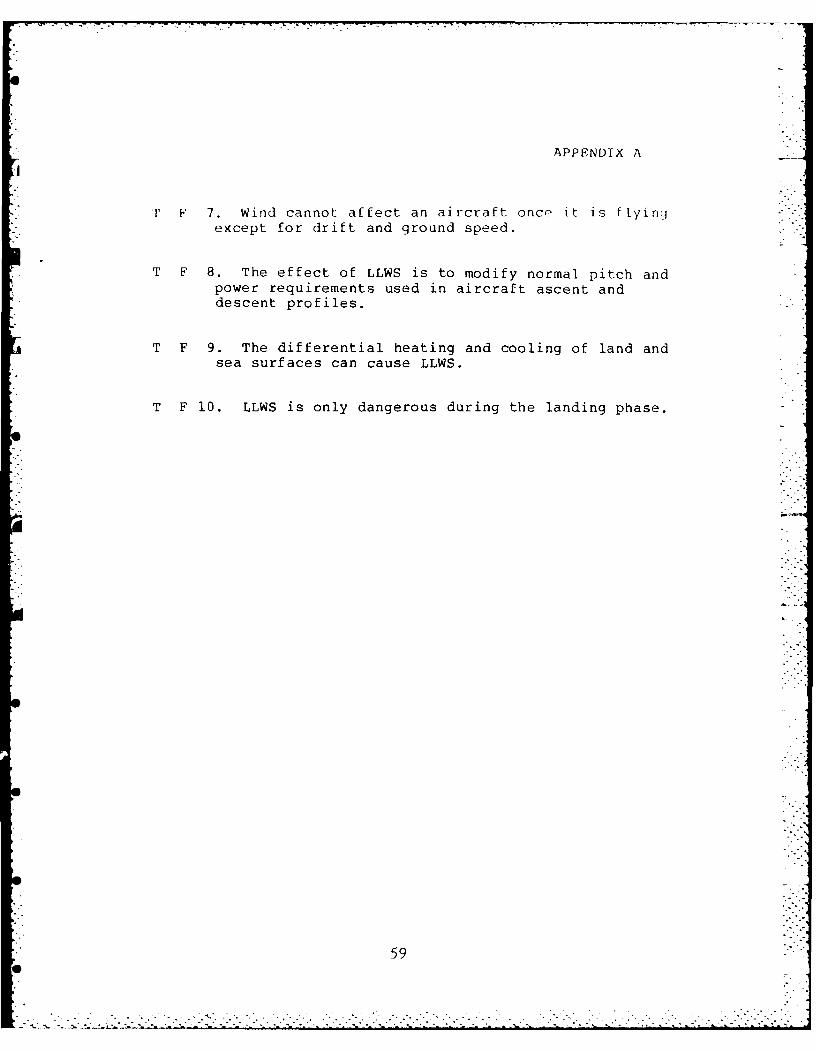
APPENDIX A
F 7. Wind cannot affect an aircraft once it is ftying-except for drift and ground speed.
T F 8. The effect of LLWS is to modify normal pitch andpower requirements used in aircraft ascent anddescent profiles.
T F 9. The differential heating and cooling of land andsea surfaces can cause LLWS.
T F 10. LLWS is only dangerous during the landing phase.
59
0..-

APPENDIX A
ANSWERS TO EXAMINATIONS
EXAM-#I
MULTIPLE CHOICE:
QUESTION # ANSWER REFERENCE PAGE
1.A 32. B 43. D 44. C 4
5.B 96. D 77. A 78. B 89. B 8
10.D 811.D 10
12. C 1213. B 1214. 0 615. A 6
TRUE OR FALSE
QUESTION # ANSWER REFERENCE PAGE
1. F 42. F 53. T 11
4.T 95. F 11
T i7. F 4
H. T 49. T 12
10. F 4
6o

APPENDIX A
TEST # 2
MULTIPLE CHOICE
1. Why is low level wind shear considered the mostdangerous type wind shear?
A. Because the shear at low levels is usually soviolent that aircraft recovery is impossible.
B. Because it is most likely to affect the aircraftin a vulnerable condition of high-drag and lowairspeed.
C. Because shear at low levels will have moreturbulence associated with it.
D. Because thunderstorms are more likely to cause lowlevel wind shear.
2. How does a LLWS-caused change in relative airflow overan aircraft's wings affect the aircraft's performance?
A. It reduces the aircraft's accelerationcapabilities.
B. The aircraft's performance is reduced because liftis reduced.
C. The aircraft's performance is either reduced orincreased because lift is either increased ordecreased.
D. LLWS does not affect the relative airflow of windover an aircraft's wings.
61

APPENDIX A
3. All of the following,except one, are factors that havea bearing on the effects of wind shear.
A. Ability of the flight crew to respond.
B. Aircraft speed and engine response.
C. Aircraft aerodynamic characteristics and aircraftconfiguration.
D. Amount of rain present in the wind shear.
4. For which type aircraft is the greatest hazard of LLWSlikely to be on takeoff, instead of during an approach?
A. Both large and small aircraft.
B. Only small under-powered aircraft
C. Only large aircraft.
D. Heavy aircraft and ones that take time toaccelerate to their best climb speed.
5. Which of the general type clac-ses of LLWS is consideredthe most dangerous?
A. Thunderstorms.
B. Horizontal shears.
C. Low level inversions.
D. Vertical shears.
62

APPENDIX A
6. In which area/areas of a thunderstorm can LLWS b4,-present?
A. On all sides of the thunderstorm..
B. Only on the side of the thunderstorm where
downdrafts are present.
C. Only in the first gusts area of the thunderstorm..
D. In any area of the thunderstorm where strong windsare present.
7. What phenomena in high based cumulus clouds producesLLWS?
A. The combination of rain chilling and evaporationcooling of downdrafts.
B. The first gust phenomena.
C. Strong surface winds in conjunction withturbulence.
D. Cool surface temperatures and wet surface air.
8. Which of the following in not true concerning LLWSassociated with fronts?
A. All fronts have associated wind shear.
B. Both warm and cold fronts can cause LLWS.
C. Warm fronts usually produce the most dangerousLLWS.
D. LLWS associated with cold fronts usually occursafter frontal passage at the airfield.
63
.......................................

APPENDIX A-
9. LLWS associated with land/sea breezes is caused by whichof the following?
A. Heating of the land and sea surfaces.
B. Turbulence found in the cool air coming from the seawhich encounters warm air from the land.
C. Differential heating or cooling of the land and seasurfaces.
D. Breezes coming off the sea are accelerated by therise in terrain as it passes over the land mass.
10. is a doppler radar system that will improve therecognition of wind shear, gust-fronts, downbursts, and otherpotentially hazardous weather conditions.
A. LLWSAS
B. NEXRAD.
C. JAWS.
D. NCAR.
11. Why is the current FAA LLWSAS considered inadequate todetect and warn of microburst occurrence?
A. Because the present LLWSAS system is not installedat all airports that could experience LLWS.
B. Because only airborne detection systems can do thejob.
C. Because microbursts are smaller than the LLWSASdetection scale.
D. Because microbursts are larger than the LLWSAScdtect ion scale.
64
-.. -. "- . .i-

APPENDIX A
12. The infrared(IR) band radiometer has been used tosuccessfully detect LLWS from an airborne platform by:
A. measuring the drop in temperature from the ambientnon-sheared environment to the sheared environment.
B. measuring the difference in wind speed between theshear and non-shear area with C02 molecular spectrumdevice.
C. a shaped mosaic of detectors utilizing a commonoptical system thus providing the pilot with avoidancealternatives.
D. measuring the moisture differential between theshear and non-shear area.
13. Which of the following airspeeds is considered themost reliable indication to the pilot when experiencingLLWS?
A. Indicated airspeed.
B. MACH indicator.
C. Ground speed.
D. True airspeed.
14. Which is the correct aircraft reaction to a horizontalshear which is an increasing headwind?
A. IAS increases, lift decreases, and the aircraftpitchs up.
B. IAS and lift increases, and the aircraft pitchsdown.
C. IAS decreases, lift increases, and the aircraftpitchs up.
D. Indicated airspeed increases, lift increases, andthe aircraft pitchs up.
65
i ¢ -:-: i¢ -•.. . -: --.-.i . ~i .; .;. i ¢ _ _, _ .Lh;% i - i.- i

APPENDIX A
15. Which general type of wind shear is a pilot mostlikely to encounter?
A. Microbursts.
B. Fronts.
C. Land/sea breezes.
D. Horizontal wind shears.
TRUE OR FALSE QUESTIONS
Circle the most correct answer of the following questions.
T F 1. Of the two types of horizontal wind shears, onlythe decreasing headwind is a decreasing performancesituation.
T F 2. When faced with a LLWS encounter, loss ofairspeed is more important than flight path control.
T F 3. Probably the best indication to the pilot thatthe aircraft is encountering LLWS in on theaircraft instruments.
T F 4. Pilots should not be responsible for LLWSavoidance because of its insidiousness.
T F 5. There has been little progress in airborneequipment development which will detect LLWS.
I' F 6. Any time a radiational inversion is present,tVw pw,;;i i l ity of LLW ; oxi "t .
66
.. ".

APPENDIX A
T F 7. The probability of getting grabbed by amicroburst is high, but the consequences
if you do are low.
T F 8. Microbursts have only recently been identified -
during the mid-1970s.
T F 9. The only real difference between macrobursts andmicrobursts is their size and duration.
T F 10. LLWS is shear occurring between the surface and1,500 feet AGL.
67

[i
AF 1 [) L ,
ANSWERS TO EXAMINATIONS
EXAM # 2
MULTIPLE CHOICE:
QUESTION # ANSWER REFERENCE PAGE
1. B 3
2. C 33. D 34. D 45. D 56. A 67. A 7
8. A 12
9. C 1310. B 17
Ii. C 1912. A 2013. C 3214. D 3415. D 33
TRUE OR FALSE
QUESTION # ANSWER REFERENCE PAGE
1. T 362. F 313. T 254. F 285. F 226. T 157. F 128. F 9
9. T 810. F 3
6 ..

___ ___ ___ ___ __ APPENDIX _ _ _ _ _ _ _ _ _
APPENDIX B
HANDBOOK
ON
RECOGNITION AND CONTROL OF LOW LEVEL WIND SHEAR HAZARDS
93BMW/SIFC
CASTLE AFB, CA
69

APPENDIX 2
EFFECTS OF LOW LEVEL WIND SHEAR
1. DEFINITIONS:
*WIND SHEAR: "Wind shear" is a change in wind speed
and/or direction over a short distance, which results ina tearing or shearing action. The term "wind shear"refers to the shearing or scissor-like action of two airmasses moving in relation to one another.
*LOW LEVEL WIND SHEAR(LLWS): "Low level wind shear" is
shear occurring between the surface and 2,000 feet AGL,where the greatest accident potential for takeoff andlanding exist.
2. TWO GENERAL CLASSES OF WIND SHEARS:
*HORIZONTAL: Horizontal wind sheais are present just
about everywhere, but they are not as dangerous asvertical wind shears because the velocities and rates ofchange are smaller. These small changes usually permitpilots and airplanes to adjust safely and in a timelymanner. The effects of horizontal wind shears aresudden changes in rate of climb or descent, or inposition with respect to the glideslope, and are alwaysaccompanied by changes in airspeed.
*VERTICAL: Vertical shears are more serious and onlyrecently discovered(1975). They occur mostly aroundthunderstorms and fronts. Sudden changos in rate ofclimb or d3scent caused by vertical wind shears is notaccompanied by changes in airspeed, only angle of attacki ,rd v, 1. i1 ,1 v,.I (L Ly change.
70
- *. -! S -•f i

APPENDIX B
3. FACTORS HAVING A BEARING ON THE EFFECTS OF LLWS:
*AIRCRAFT CONFIGURATION: Aircraft configuration for
takeoff and landing usually includes gear and flaps.This high drag, low-airspeed condition makes theaircraft very vulnerable to LLWS hazards.
*AIRCRAFT SPEED: In general, the higher the airspeedfor a given configuration, the less LLWS will affect theaircraft's flight path. However, attitude often mustalso be increased to take advantage of the increased
* airspeed.
*AERODYNAMIC CHARACTERISTICS: In general, the more
swept back the wings of an aircraft, the less effectivpthe wings are at producing lift when at slow airspeeds.
*POWER/WEIGHT RATIO: Obviously, the greater the powerto weight ratio an aircraft has the faster it willaccelerate which is an aid in recovery from severe LLWS.
*ENGINE RESPONSE: High performance, jet aircraft havemany advantages over slower propeller aircraft.However, one disadvantage of jet aircraft is longerspool up time for acceleration. This is especially trueof heavy, wide-bodied aircraft.
*FLIGHT CREW RESPONSE: When experiencing LLWS the crewmust first detect the dangerous situation and then makethe proper response. Both these required events taketime. Unfortunately, time may not be available when nearthe ground.
,'.°.
0 : . . . ."• • • - - . • . . - ' ' - - . " - : -

APPENDIX B
CAUSES OF LOW LEVEL WIND SHEAR HAZARDS
1. THUNDERSTORMS: Wind shear hazards associated withthunderstorms are the most hazardous due to the severity,:omplexity, and multiplicity of the shears produced.
*CAUS.-TION CATEGORIES: LLWS hazards associated with
thunderstorms can be grouped into four categories basedon size, duration, and effects.
**HIGH--BASED CUMULUS CLOUDS: High-based innocuous-
appeating, cumulus clouds can be the root of severewind shear. LLWS can be expected under high-basedcumulus clouds when: Virga is present; surface airis ve r dry with dew point spread of 35 degrees For more; surface winds are weak, less than 15knot-s; and surface temperature is warmer than 75doq res F.
IJ*FIRST GUSTS: The first gust is a rapid shift andincrease in wind just before a thunderstorm hits -
jip to 15 miles ahead of storm.
* *LARGE DOWNBURSTS OR "MACROBURSTS": The downburst
is an extremely intense localized downdraft from athunderstorm. The macroburst ranges in width from2.6 NM to 12.5NM and in duration from five to 20minutes.
**"MICROBURSTS": Its the intensity, compactness,
"nd short-live' nature of microbursts that maYthm so insidiously dangerous(most danqrous of allhazards). Microbursts are .25 to 2.5 NM in diameterand two to ton minutes in duration.
2. "ON'YC: Aft-r thundrstorms, certain front al syst,-,s .r
tri mot prominent ca(use of significant LIWS hazards. R'-t hSwarrn cnd cr1 C r_;ts cauce significant wind sIv-ars.
. . .I= _ : . : : : . - -,. : , . . - _ _ - : : : .1 . .- : . - : : - •.,,:, - " " " " "

APPENDIX B
*WARM FRONTS: Wind shear associated with a warm front
is more dangerous than cold front wind shear becausewarm front winds are more severe and low visibilitiesare usually also present. LLWS usually reaches theairfield six to 12 hours before warm frontal passage.
*COLD FRONTS: LLWS hazards associated with a cold frontare usually less dangerous because normally the dangerarea is of shorter duration and no low visibilitiesaccompany the maximum winds. LLWS will occur 30 minutesto one hour after cold frontal passage at the surface.
3. LAND/SEA BREEZE PHENOMENON: Differential heating andcooling of land and sea surfaces can cause severe LLWS. Thesea breeze is a small scale frontal boundary and reaches itsmaximum penetration in mid to late afternoon. Land breezesoccur at night because the land becomes cooler than the " -
water.
4. MOUNTAIN WAVES OR FUNNELING WINDS: Wind passing over orby rising terrain is accelerated and can cause severe LLWSwhen it spills into an aircraft's flight path.
5. LOW LEVEL JETS OVER RADIATION INVERSIONS: Overnightcooling of land can create a temperature inversion a few
* hundred feet above the ground. This, coupled with high windsfrom what is know as the low level jet, can producesignificant LLWS.
7..J.. :.- ---. ,-.--.-....,......2 . . .. "-

APPENDIX B
RECOGNITION AND DETECTION OF LLWS
1. MAGNITUDE OF THE DETECTION PROBLEM: Weather radar had tobe modified to detect wind shear(NEXRAD). Wind shear can notbe seen, and a large volume of air must be searched if allmajor airports are to be protected.
2. RESEARCH FOR POSSIBLE SOLUTIONS TO WIND SHEAR DETECTION:Investigation of a 1975 accident of a Boeing 727 at KennedyAirport led to the conclusion that it had encounteredvertical gusts so powerful that it could not climb throughthem to remain on the glideslope. The idea of vertical gustsso intense that recovery was not possible led to manyGovernment sponsored studies.
*JOINT AIRPORT WEATHER STUDIES(JAWS): A $2.2 million
dollar, three-year project conducted by the NationalCenter for Atmospheric Research and the University ofChicago with principal funding from the National ScienceFoundation. The principle objectives of JAWS was toacquire additional basic knowledge on microbursts andtheir environment to help scientist understand whatcauses them and how they can be detected and predicted.
*HEARING BEFORE U.S. CONGRESS(HOUSE) COMMITTEE ON
SCIENCE & TECHNOLOGY: Hearing was mandated by U.S.Congress to address the need for improvement of windshear detection methods.
3. AREAS OF POSSIBLE SOLUTIONS RESULTING FROM RESEARCH:
*FORECASTING AND PREDICTION IMPROVEMENTS: Studies
called for the development of the Next-GenerationWeather Radar System(NEXRAD). The NEXRAD is a dopplerradar systern that will improve the -ecognition of wind
(4L St fronts, downhursts, a1:.I ot h 1r o nt a l .yhaz, rdous Wlh,'r conditions.
7 h%

APPENDIX B
*GROUND-BASED SENSORS: Many airports have ground
detectors known as Low Level Wind Shear Alert
Systems(LLWSAS). The LLWSAS consists of an array ofwind sensors distributed about the airport and connected
to a central processor that sounds an alarm to the towerwhenever the wind vectors at two sensors differ by 15knots or more.
*AIRBORNE DETECTION DEVICES: Airborne flightsimulations to evaluate airborne devices for thedetection and display of wind shear information in thecockpit have been conducted for transport categoryaircraft over the past several years. Both lidar radarand infrared(IR) forward-looking thermal radiometerdetectors were successful in detecting the presence ofwind shear by measuring temperature differentials.However, the research done thus far has been able toonly give limited warning times and distances. Currentresearch is continuing with the hope of giving from 3 to7 NM warning of impending LLWS.
4. STATUS OF USAF ON STATE-OF-THE-ART DETECTION EQUIPMENT:Today, the Air Force does not have the equipment forcontinuous, accurate measurement or detection of LLWS in thevicinity of its airfields. The Air Force has proposed thedevelopment of a Low Altitude Wind Warning System(LAWWS).The approval, funding and development of the proposed LAWWShave not yet been completed, but positive action is beingtaken to provide an operational system in the future.
5. INFORMATION SOURCES FOR LLWS: There are numerousinformation sources available for LLWS detection.
75

APPENDIX B
*PREFLIGHT WEATHER FORECASTS: The best way toanticipate LLWS for departure or at your destination isfrom the preflight weather briefing. Don't hesitate toask the forecaster about the possibilities of LLWS.
*PIREPS: PIREPS are a major source of weatherinformation; they provide real-time data to the weatherforecaster. When you call in for your landing weatherbe sure to ask if any LLWS has been reported.
*PMSV AND AIR TRAFFIC CONTROL: These are excellent
sources to keep you updated on both the latest weatherinformation and the latest PIREPS.
*AIRCRAFT INSTRUMENTS: Pilots flying aircraft with
ground speed readouts should compare the winds at theinitial approach altitude with reported runway surfacewinds to see if LLWS is likely. For aircraft withoutground speed readouts, monitoring aircraft performancecan reveal the presence of LLWS. By observing theaircraft's approach parameters, the pilot can determineif LLWS is present.
HOW TO CONTROL AND COPE WITH LLWS
1. ULTIMATE RESPONSIBILITY FOR SAFETY RESTS WITH PILOT:There is no question crews are better equipped to deal with
LLWS now than at any time in the past, thanks to newtechnology. However, the ultimate responsibility for safetyof flight must still be based on pilot or aircrew judgment.
2. DIFFERENT TECHNIQUES FOR DIFFERENT TYPES OF WIND SHEAR:Crew response to LLWS depends on whether the wind shear is avef tical or horizontal shear.
76
I-

APPENDIX B
*VERTICAL WIND SHEAR("MICROBURSTS"): An encounter with
a vertical wind shear is less likely, but extremelydangerous. There are two schools of thought on how tooptimize aircraft performance during an encounter with a
vertical shear. One technique involves flying out at
the minimum drag speed, while the second is called the
"stick shaker" method.
**FLYING AT MINIMUM DRAG SPEED: Many pilots have
been trained to lower the nose to pick up airspeedwhen it is falling off. In a LLWS situation, thiscould be fatal. You have traded too much potentialenergy for kinetic energy. When encounteringmicroburst conditions near the ground, lowering thenose of your aircraft results in a further, morecritical reduction in AOA, a significant loss ofaltitude, a degradation in climb performance, andprobably ground impact.
**"STICK SHAKER" METHOD: A more favorable
alternative would be to apply maximum thrust whilesmoothly increasing pitch attitude until thedescent is arrested or a stick shaker condition isreached.
*HORIZONTAL WIND SHEAR: The horizontal wind shear is
more frequent, but less dangerous. This type shear is
usually more gradual and the pilot and aircraft havemore time to make adjustments. Horizontal shears fitinto two categories: increasing headwinds; anddecreasing headwinds.
77

APPENDIX B
**INCREASING HEADWIND: Performance increasingsituation is created here.
***TAKEOFF PROCEDURES: Takeoff into anincreasing headwind shear is no problem asperformance is increasing.
***LANDING PROCEDURES:
****Do not pad approach speed. If shearexists, indicated airspeed and lift willincrease.
****If shear is close to the ground(pastdecision height), it might cause a long,hot landing. Go around, if unable toland in touchdown zone.
****If shear is encountered at a higheraltitude, resist the temptation to make alarge power reduction. Accept higherindicated airspeed and use pitch and trimto get back to glide path, if possible.But avoid large trim changes.
****Avoid high descent rates with theengines spooled down. If you can'trestabilize on glide path, go around.
**DECREASING HEADWIND: Decreasing performance
situation exists here, as ground speed is lowerthan reference ground speed.
78" . . . . . . . . .

APPENDIX B
***TAKEOFF PROCEDURES:
****Delay takeoff, if possible.
****Pad rotate and climbout airspeeds,
runway and obstacles permitting.
****If unable to delay takeoff, let
airspeed build as soon as possible aftertakeoff and delay flap retraction untilthe upper limits of the flap retractionschedule.
***LANDING PROCEDURES:
****Pad approach airspeed by the amount
of the shear potential.
****Be aware of stopping distance. This
should rarely be a limiting factor,considering the length of SAC runways andnormal landing gross weights. However,watch with low RCPs.
****Monitor ground speed. If it
increases gradually(no shear exists),then anticipate the need to reduce powerand increase descent rate in the finalpart of the approach.
****Avoid high descent rates with engines
spooled down.
****If a go around is necessary, use full
thrust. Don't be shy!
79

APPENDIX B
3. REFERENCE GROUND SPEED: Using ground speed as areference during an approach when LLWS is suspected isimportant because it insures flying airspeed at all times,even in abrupt wind shear situations. Ground speed as aparameter is a radical departure from the school of thoughtthat says a stabilized and constant indicated airspeed withvery small power changes will result in the best precisionapproach.
80
___ ___ ___ ___ __APPENDIX _ _ _ _ _ _ _ _ _
APPENDIX C
SOUND-ON-SLIDE SCRIPT
ON
RECOGNITION AND CONTROL OF LOW LEVEL WIND SHEAR HAZARDS
93BMW/SIFC
CASTLE AFB, CA

APPENDIX C
SOUND-ON-SLIDE SCRIPT
-'SLIDE 1 (TITLE OF COURSE)
RECOGNITION AND CONTROL OF LOW LEVEL WIND SHEAR HAZARDS
SLIDE 2 (WHY STUDY LLWS?)
From 1962 to 1982, there were 127 U.S. Air Carrieraccidents in which thunderstorms/LLWS hazards were found tobe either a cause or a factor. These accidents cost 545lives and 260 injuries. From 1965 to 1974, the USAFexperienced 41 probable wind shear/vortex related aircraftaccidents - the total price tag was $18 million dollars.
SLIDE 3 (OUTLINE OF COURSE)
I. EFFECTS OF LOW LEVEL WIND SHEAR
11. CAUSES OF LOW LEVEL WIND SHEAR
III. RECOGNITION AND DETECTION OF LOW LEVEL WIND SIEAR
IV. HOW TO CONTROL AND COPE WITH LOW LEVEL WIND SHEAR
SLIDE 4 (EFFECTS OF LOW LEVEL WIND SHEAR)
I. DEFINITIONS
I. CLASSES OF WIND) SHEAR
III. FACTORS HAVING A BEARING ON EFI.,ECTS OF LLWS
C)').<.

A
APPENDIX C
SLIDE 5 (DEFINITION OF WIND SHEAR)
Wind shear is a change in wind speed and/or direction
over a short distance, which results in a tearing or shearingaction. The term "wind shear" refers to the shearing orscissor-like action of two air masses moving in relation toone another.
* SLIDE 6 (DEFINITION OF LOW LEVEL WIND SHEAR)
"Low level wind shear" is shear occurring between thesurface and 2,000 feet AGL, where the greatest accident
potential for takeoff and landing exist.
SLIDE 7 (TWO GENERAL CLASSES OF WIND SHEAR)
*HORIZONTAL SHEAR
*VERTICAL SHEAR
SLIDE 8 (HORIZONTAL SHEARS)
Horizontal wind shears are present just abouteverywhere, but they are not as dangerous as vertical shearsbecause the velocities and rates of change are smaller.These small changes usually permit pilots and airplanes toadjust safely and in a timely manner. The effects o-horizontal wind shears are sudden chanqes in rate of climb ordescent, or in position with respect to the glideslope, andare always accompanied by changes in indicated/ground speed.
- - - - - - - - - - - - -

APPENDIX C
iSLIDE 9 (VERTICAL SHEARS)
Vertical shears are more serious and only recently havebeen discovered(1975). They occur mostly aroundthunderstorms and fronts. Sudden changes in rate of climb ordescent caused by vertical wind shears is not accompanied bychanges in airspeed, only angle of attack and verticalvelocity change.
SLIDE 10 (FACTORS HAVING A BEARING ON THE EFFECTS OF LLWS)
1. AIRCRAFT CONFIGURATION
2. AIRCRAFT SPEED
3. AERODYNAMIC CHARACTERISTICS
4. POWER/WEIGHT RATIO
5. ENGINE RESPONSE
6. FLIGHT CREW RESPONSE
SLIDE 1l (AIRCRAFT CONFIGURATION)
Aircraft configuration for takeoff and landing usuallyincludcs oear and flaps. This high drag, low-airspeedcondition makes the aircraft very vulnerable to LLWS hazard, -
and inhibits acceleration.
-. 0 l
0

APPENDIX C
SLIDE 12 (AIRCRAFT SPEED)
In general, the higher the airspeed for a givenconfiguration, the less LLWS will affect the aircraft'sflight path - assuming proper corrective actions are taken.
SLIDE 13 (AERODYNAMIC CHARACTERISTICS)
In general, the more swept back the wings of anaircraft, the less effective the wings are at pro-ucing liftwhen at slow airspeeds. Also drag affects accelerationrates.
SLIDE 14 (POWER/WEIGHT RATIO)
Obviously, the greater the power to weight ratio of anaircraft, the faster it will accelerate which is an aid inrecovery from severe LLWS.
SLIDE 15 (ENGINE RESPONSE)
High performance, jet aircraft have many advantages overslower propeller aircraft. However, one disadvantage of jetaircraft is longer spool up time for acceleration. Thi.s isespecially true of heavy, wide-bodied jet aircraft.
SLIDE 16 (FLIGHT CREW RESPONSE)
This is the most important factor. When experiencingLLWS the crew must first detect the dangerous situation andthen make the proper response. Both these required eventstake time. Unfortunately, time may not be available wh: nnear the ground.
---- ---- -- -- --

COMMAND AND STAFF COLL MAXWdELL AFB AL W G ROGERSAPR 85 RCSC-85-2215
UN C L A WIfl-a
IR 1650 RCGIINRDCNRLO O EE IDSER I /

.4
1111 I f I~ 1 1.8 j
1111.25 11111 111 U.6
MICROCOPY RESOLUTION TEST CHART
NATIONAL BUREAU OF~ STANDARDS-1963-A
E4

APPENDIX C
.
SLIDE 17 (CAUSES OF LLWS)
1. THUNDERSTORMS
2. FRONTS
3. LAND/SEA BREEZES
4. MOUNTAIN WAVES OR FUNNELING WINDS
5. LOW LEVEL JETS OVER RADIATION INVERSIONS
SLIDE 18 (THUNDERSTORMS)
Wind shear hazards associated with thunderstorms are themost hazardous due to the severity, complexity, andmultiplicity of the shears produced.
SLIDE 19 (THUNDERSTORM CAUSATION CATEGORIES)
LLWS hazards associated with thunderstorms can begrouped into four categories based on size, duration, andeffects.
1. HIGH-BASED CUMULUS CLOUDS
2. FIRST GUSTS
3. LARGE DOWNBURSTS OR "MACROBURSTS"
4. SMALL DOWNBURSTS OR "MICROBURSTS"
m. . -
86

--.-.- .
APPENDIX C
SLIDE 20 (HIGH-BASED CUMULUS CLOUDS)
High-based, innocuous-appearing cumulus clouds can bethe root of severe wind shear. LLWS can be expected underhigh -based, cumulus clouds when: Virga is present; surfaceair is very dry with dew point spread of 35 degrees F ormore; surface winds are weak, less than 15 knots; and surfacetemperature is warmer than 75 degrees F.
SLIDE 21 (FIRST GUSTS)
The first gust is a rapid shift and increase in windjust before a thunderstorm hits - up to 15 miles ahead.
- - - - - - - - - - - - -
SLIDE 22 (LARGE DOWNBURSTS OR "MACROBURSTS")
The downburst is an extremely intense localizeddowndraft from a thunderstorm. The "macroburst" ranges inwidth from 2.6 NM to 12.5 NM and in duration from five to 20minutes.
SLIDE 23 ("MICROBURSTS")
Its the intensity, compactness, and short-lived natureof microbursts that make them so insidiously dangerous. Theyare the most dangerous of all hazards. Microbursts are .25to 2.5 NM in diameter and two to ten minutes in duration.
SLIDE 24 (FRONTS - WARM AND COLD)
After thunderstorms, certain frontal systems are themost prominent cause of significant LLWS hazards. Both warmand cold fronts cause significant wind shears.
87
. . .. . . . . . . . .. . . . . .
°. . . . . . . . . . . .. .. . ... °- *° . • . . . °

...
APPENDIX C
SLIDE 25 (WARM FRONTS)-
Wind shear associated with a warm front is moredangerous than a cold front wind shear because warm front ',-winds are more severe and low visibilities are usuallypresent. LLWS usually reaches the airfield six to 12 hoursbefore warm frontal passage.
SLIDE 26 (COLD FRONTS)
LLWS hazards associated with a cold front are usuallyless dangerous because normally the danger area is of shorterduration and no low visibilities are present. LLWS willoccur 30 minutes to one hour after cold frontal passage at -5
the surface.
SLIDE 27 (LAND/SEA BREEZE PHENOMENA)
Differential heating and cooling of land and seasurfaces can cause LLWS. The sea breeze is a small scalefrontal boundary and reaches its maximum penetration in midto late afternoon. Land breezes occur at night because theland becomes cooler than the water.
SLIDE 28 (MOUNTAIN WAVES OR FUNNELING WINDS)
Wind passing over or by rising terrain is acceleratedand can cause wind shear when it spills into an aircraft'sflight path.
SLIDE 29 (LOW LEVEL JETS OVER RADIATION INVERSIONS)
Overnight cooling of land can create a temperatureinversion a few hundred feet above the ground. This, coupledwith high winds from what is known as the low level jet, canproduce significant wind shears near the ground.
--- --- --- --- ---
88
............................................ % -:
* *. . . . . . .

r
APPENDIX C,% -..
SLIDE 30 (RECOGNITION AND DETECTION OF LLWS)
1. MAGNITUDE OF THE DETECTION PROBLEM
2. RESEARCH FOR SOLUTIONS TO LLWS DETECTION PROBLEM
3. SOLUTION AREAS RESULTING FROM RESEARCH
4. STATUS OF USAF ON STATE-OF-THE ART DETECTIONEQUIPMENT
5. INFORMATION SOURCES FOR LLWS
---
SLIDE 31 (MAGNITUDE OF DETECTION PROBLEM)
Weather radar had to be modified to detect windshear(NEXRAD). Wind shear can not be seen, and a largevolume of air must be searched if all major airports are tobe protected.
SLIDE 32 (RESEARCH FOR SOLUTIONS TO DETECTION PROBLEM)
1. JOINT AIRPORT WEATHER STUDIES(JAWS)
2. CONGRESSIONAL HEARING
Investigation of a 1975 accident of a Boeing 727 atKennedy Airport led to the conclusion that it had encounteredvertical gusts which caused the crash. The idea of verticalgusts so powerful that recovery was not possible led to manyGovernment sponsored studies.
89

APPENDIX C
SLIDE 33 (JAWS)
A $2.2 million dollar, three-year project conducted bythe National Center for Atmospheric Research and theUniversity of Chicago with principal funding from theNational Science Foundation. The principal objectives of "JAWS was to acquire additional basic knowledge on microburstsand their environment to help scientist understand whatcauses them and how they can be detected and predicted.
SLIDE 34 (CONGRESSIONAL HEARING ON LLWS)
Hearing was mandated by US Congress to address the needfor improvement of wind shear detection methods andequipment.
SLIDE 35 (POSSIBLE SOLUTIONS RESULTING FROM RESEARCH)
1. FORECASTING AND PREDICTION IMPROVEMENTS
2. GROUND-BASED SENSORS
3. AIRBORNE DETECTION DEVICES
SLIDE 36 (FORECASTING AND PREDICTION IMPROVEMENTS)
Studies called for the development of the Next-Generation Weather Radar(NEXRAD). The NEXRAD is a dopplerradar system that will improve the recognition of wind shear,gust-fronts, downbursts, and other potentially hazardousweather conditions.
I0
90 , .
* . ,* *°**. *.-
, ..... .. , .. . . ,. .. , .. .. .. -.- -.. . --. --. . . . ." -- - "-.- -. . . . ..- -'-,,' ."

* '. -. . , - C I- . * ... - .. * ~ .. , - - -
''°.
APPENDIX C
SLIDE 37 (GROUND-BASED SENSORS)
Many airports have ground detectors known as Low LevelWind Shear Alert Systems(LLWSAS). The LLWSAS consists of anarray of wind sensors distributed about the airport andconnected to a central processor that sounds as alarm to thetower whenever the wind vectors at two sensors differ by 15knots or more.
SLIDE 38 (AIRBORNE DETECTION DEVICES)
Airborne flight simulations to evaluate airborne devicesfor the detection and display of wind shear information inthe cockpit have been conducted for transport categoryaircraft over the past several years. Both lidar radar andinfrared(IR) forward-looking thermal radiometer detectors -were successful in detecting the presence of wind shear up tothree miles in front of the test aircraft.
SLIDE 39 (STATUS OF USAF ON STATE-OF-THE ART DETECTIONEQUIPMENT)
Today, the Air Force does not have the equipment forcontinuous, accurate measurement or detection of LLWS in thevicinity of our bases. The Air Force has proposed thedevelopment of a Low Altitude Wind Warning System(LAWWS). Theapproval, funding and development of the proposed LAWWS havenot yet been completed, but positive action is being taken toprovide an operational system in the future.
SLIDE 40 (INFORMATION SOURCES FOR LLWS)
There are numerous information sources available forLLWS detection:
91
°a ° ° * * , °° .. . ° ° . . . . . . . . . ° - . . . . . -...-. . . . ., * --. .* . o- . -.. *.-*

, *. . , . . . . ... . . . . o_ . . . ..r. . ..
APPENDIX C
1. PREFLIGHT WEATHER FORECASTS
2. PIREPS
3. PMSV AND AIR TRAFFIC CONTROL
4. AIRCRAFT INSTRUMENTS
SLIDE 41 (PREFLIGHT WEATHER FORECASTS)
The best way to anticipate LLWS for departure or at your* destination is from the preflight weather briefing. Don't
hesitate to ask the forecaster about the possibilities ofLLWS.
U.-.
" SLIDE 42 (PIREPS)
PIREPS are a major source of weather information; theyprovide real-time data to the weather forecaster. When youcall in for your landing weather be sure to ask if any LLWShas been reported.
SLIDE 43 (PMSV AND AIR TRAFFIC CONTROL)
These are excellent sources to keep you updated on boththe latest weather information and the latest PIREPS.
SLIDE 44 (AIRCRAFT INSTRUMENTS)
Pilots flying aircraft with ground speed readouts shouldcompare the winds at the initial approach altitude withreported runway surface winds to see if LLWS is present. Foraircraft without ground speed readouts, monitoring aircraftperformance can reveal LLWS. By observing the aircraft's.pproach parameters, the pilot can determine if LLWS ispresent.
92
....................................... . .... ... .... ... ...

APPENDIX C
SLIDE 45 (HOW TO COPE WITH LLWS)
1. ULTIMATE RESPONSIBILITY FOR SAFETY RESTS WITH PILOT
2. DIFFERENT TECHNIQUES FOR DIFFERENT TYPES OF LLWS
3. REFERENCE GROUNDSPEED
- - - - - -
SLIDE 46 (PILOT HAS ULTIMATE RESPONSIBILITY)
There is no question crews are better equipped to dealwith LLWS now than at any time in the past, thanks to newtechnology. However, the ultimate responsibility for safetyof flight must still be based on pilot judgment.
3 SLIDE 47 (DIFFERENT TECHNIQUES FOR DIFFERENT TYPE LLWS)
Crew response to LLWS depends on whether the wind shear
is a vertical or horizontal shear.
1. VERTICAL WIND SHEAR
2. HORIZONTAL WIND SHEAR
SLIDE 48 (VERTICAL WIND SHEAR - "MICROBURSTS")
An encounter with a vertical wind shear is less likely,but extremely dangerous. There are two schools of thoughton how to optimize aircraft performance during an encounterwith a vertical shear. One technique involves flying out atthe minimum drag speed, while the second is called the "stickshaker" method.
1. FLYING AT MINIMUM DRAG SPEED
2. STICK SHAKER SPEED
93

APPENDIX C
SLIDE 49 (FLYING AT MINIMUM DRAG SPEED)
Many pilots have been trained to lower the nose to pickup airspeed when it is falling off. In a LLWS situation,this could be fatal. You have traded too much potentialenergy for kinetic energy. When encountering microburstconditions near the ground, lowering the nose of youraircraft results in a further, more critical reduction inAOA, a significant loss of altitude, a degradation in climbperformance and ground impact.
SLIDE 50 (STICK SHAKER METHOD)
A more favorable alternative would be to apply maximumthrust while smoothly increasing pitch attitude until thedescent is arrested or a stick shaker condition is reached.
SLIDE 51 (HORIZONTAL WIND SHEAR)
The horizontal wind shear is more frequent, but lessdangerous. This type shear is usually more gradual and thepilot and aircraft have more time to make adjustments.Horizontal shears fit into two categories: increasingheadwinds; and decreasing headwinds.
1. INCREASING HEADWIND
2. DECREASING HEADWIND
3. REFERENCE GROUNDSPEED
94b'b
"-I
...................................................................
.- %-. - °.. .. . . . . . . . . ..... .,-. .°

* - - - - • -
APPENDIX C
SLIDE 52 (INCREASING HEADWIND)
Performance increasing situation is created here.
1. TAKEOFF PROCEDURES2. LANDING PROCEDURES
SLIDE 53 (TAKEOFF PROCEDURES)
Takeoff into an increasing headwind shear is no problemas performance is increasing.
SLIDE 54 (LANDING PROCEDURES)
1. Do not pad approach speed. If shear exists,indicated airspeed and lift increase.
2. If shear is close to the ground(past decisionheight), it might cause a long, hot landing. Go around,if unable to land in touchdown zone.
3. If shear is encountered at a higher altitude, resistthe temptation to make a large power reduction. Accepthigher indicated airspeed and use pitch and trim to getback to glide path, if possible. But avoid large trimchanges.
4. Avoid high descent rates with engines spooled down;and if you can't restabilize on glide path - go around.
SLIDE 55 (DECREASING HEADWIND)
Decreasing performance results here as ground speed islower than reference ground speed.
1. TAKEOFF PROCEDURES2. LANDING PROCEDURES
95*......t*..*.. . .. . . . .. A. . . . . . . . . .
.---- -~ -- ---- -- ~ - ---- - 7-

APPENDIX C
SLIDE 56 (TAKEOFF PROCEDURES)
1. Delay takeoff, if possible.
2. Pad rotate and climbout airspeeds by shear amount,if runway and obstacles permit.
3. If unable to delay takeoff, let airspeed build assoon as possible after takeoff, and delay flapretraction until the upper limits of the flap retractionschedule.
SLIDE 57 (LANDING PROCEDURES)
1. Pad approach airspeed by the amount of shearpotential.
2. Be aware of stopping distance. This should rarelybe a limiting factor, considering length of SAC runwaysand normal landing weights. (However, watch low RCRs).
3. Monitor ground speed. If it increasesgradually(indicates no shear exists), then anticipatethe need to reduce power and increase descent rate inthe final part of the approach.
4. Avoid high descent rates with engines spooled down.
5. If a go around is necessary, use full thrust.Simulator tests show pilots usually add less power thanthey think they did. Don't be shy.
96
.. ,. ...- .- . . . . . .. . . . . . . . .... . . . . . . . . . . . .

7 7.
APPENDIX C
SLIDE 58 (REFERENCE GROUND SPEED)
Using ground speed as a reference during an approachwhen LLWS is suspected is important because it insures flyingairspeed at all times, even in abrupt wind shear situations.Ground speed as a parameter is a radical departure from theschool of thought that says a stabilized and constantindicated airspeed with very small power changes will resultin the best precision approach.
97
.. .. .. .. . . . .. .. .

1.8.
1.25.
NATION L 2UO TNDRS16-
- ~ 1v