control of concrete cracking in bridgesonlinepubs.trb.org/onlinepubs/webinars/170817.pdf · control...
TRANSCRIPT
Thursday, August 17, 2017
2:00pm to 3:30pm ET
Control of Concrete Cracking in Bridges
TRANSPORTATION RESEARCH BOARD

The Transportation Research Board has met the standards and requirements of
the Registered Continuing Education Providers Program. Credit earned on
completion of this program will be reported to RCEP. A certificate of completion
will be issued to participants that have registered and attended the entire session.
As such, it does not include content that may be deemed or construed to be an
approval or endorsement by RCEP.
Purpose Discuss NCHRP Synthesis 500.
Learning Objectives At the end of this webinar, you will be able to: • Understand the methods used to control concrete cracking in bridge
superstructures and substructures • Understand the influence of cracking on long-term durability
NCHRP Synthesis 500:
Control of Concrete Cracking in Bridges NCHRP Project 20-05, Topic 47-01
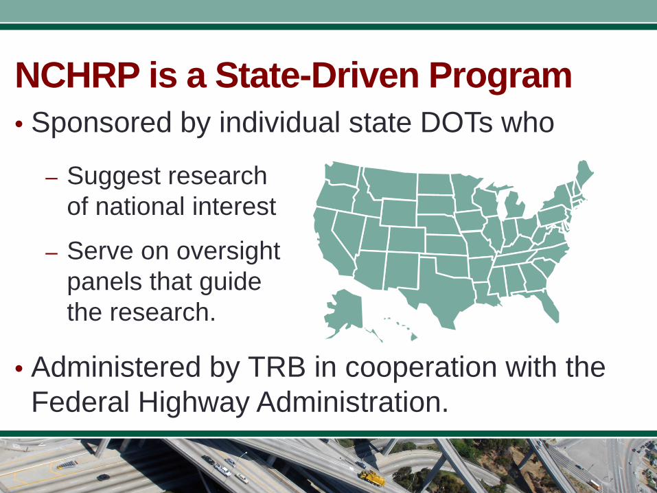
NCHRP is a State-Driven Program
– Suggest research of national interest
– Serve on oversight panels that guide the research.
• Administered by TRB in cooperation with the Federal Highway Administration.
• Sponsored by individual state DOTs who
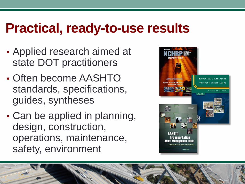
Practical, ready-to-use results • Applied research aimed at
state DOT practitioners • Often become AASHTO
standards, specifications, guides, syntheses
• Can be applied in planning, design, construction, operations, maintenance, safety, environment
Additional Publications Related to this Topic
• NCHRP Report 654: Evaluation and Repair Procedures for Precast/Prestressed Concrete Girders with Longitudinal Cracking in the Web
• NCHRP Project 20-07 Task 234 Report: Guidelines for Selection of Bridge Deck Overlays, Sealers and Treatments
You can learn more about these publications by visiting www.trb.org
Today’s Speakers
• Bijan Khaleghi, Washington State DOT Chair of Synthesis Panel and Today’s Speaker
• Ben Graybeal, Federal Highway Administration Webinar Moderator
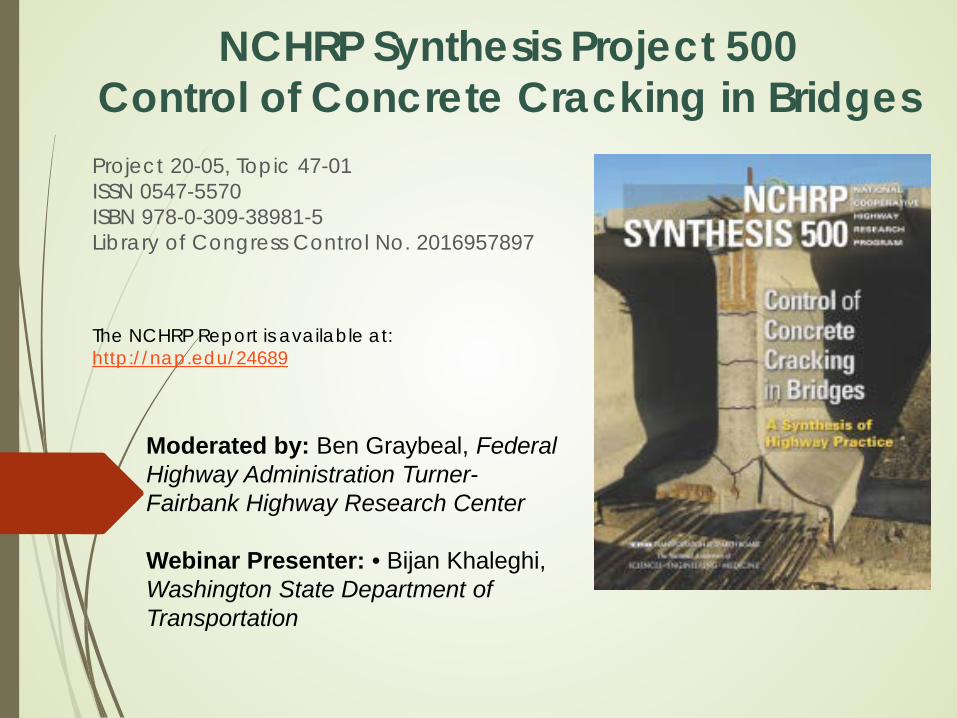
NCHRP Synthesis Project 500 Control of Concrete Cracking in Bridges Project 20-05, Topic 47-01 ISSN 0547-5570 ISBN 978-0-309-38981-5 Library of Congress Control No. 2016957897
The NCHRP Report is available at: http://nap.edu/24689
Moderated by: Ben Graybeal, Federal Highway Administration Turner-Fairbank Highway Research Center Webinar Presenter: • Bijan Khaleghi, Washington State Department of Transportation
NCHRP Program Manager: Mr. Jon Williams
Principal Investigator: Dr. Henry G. Russell
NCHRP Synthesis Panel:
JOHN BELCHER, Michigan Department of Transportation
BIJAN KHALEGHI. Washington State Department of Transportation
WILL LINDQUIST, Kansas Department of Transportation
WILLIAM POTTER, Florida Department of Transportation
CARIN L. ROBERTS-WOLLMANN, Virginia Polytechnic Institute and State University, Blacksburg
AMY E. SMITH, HDR, Austin, TX
BENJAMIN A. GRAYBEAL, Federal Highway Administration (Liaison)
REGGIE H. HOLT, Federal Highway Administration (Liaison)
NCHRP Synthesis Project 500 Control of Cracking in Bridges
NCHRP Synthesis Project 500 - Control of Concrete Cracking in Bridges
CHAPTERS: 1. Introduction 2. Types And Causes Of Concrete Cracking In Bridges 3. Effects Of Concrete Constituent Materials 4. Effects Of Construction Practices On Cracking 5. Effects Of Reinforcement Type On Crack Control 6. Effects Of Cracking On Long-term Performance 7. Case Examples 8. Conclusions and Suggestions for Future Research
APPENDICES: Survey Questionnaire, LRFD Bridge Design Specifications, Research Problem Statement
NCHRP Synthesis Project 500 Study Approach
Information for this synthesis was obtained from a literature review, surveys of state DOTs, provincial agencies in Canada, and input from individuals who have in-depth information.
The literature search provided many references related to concrete cracking.
Information gathered in this synthesis provides a basis for understanding the causes of concrete cracking in bridges and helps to establish the most practical and efficient methods for reducing the occurrence of cracking and controlling cracking when it occurs.
4
Objectives and Scope of the NCHRP Synthesis Project
Objectives of the NCHRP Project: Provide a compilation and discussion of methods
used to control concrete cracking in bridges Present information on the influence of cracking on
long-term durability. Scope: Effect of the following on control of cracking:
• Concrete mix design and performance requirements, • Construction practices, • Structural design requirements, • Steel reinforcement with yield strengths 60 -100 ksi, • Corrosion-resistant reinforcement.
Purpose of this Webinar: Overview of NCHRP Synthesis Project 500: Control of Concrete Cracking in Bridges
Learning Objectives: At the end of this webinar, you will be able to: Understand the Types And Causes Of Concrete
Cracking In Bridges Familiarize with methods used to control concrete
cracking in bridge structures Familiarize with the influence of concrete cracking
on short and long-term durability.
6 Webinar: Purpose and Objective
Selected Topics for this Webinar: Types and Causes of Concrete Cracking Cracking in Concrete Bridge Decks Cracking in prestressed concrete beams Conclusions and Suggestions for Future Research Discussion items:
o Effects of Concrete Constituent Materials o Effects of Construction Practices on Cracking o Effects of Reinf. Type on Crack Control o Influence of Cracking on Long-term Bridge
Performance
Webinar Outline-NCHRP Synthesis Project 500

Causes of Concrete Cracking in Bridges
Concrete Cracking can be classified into two categories: Cracks caused by externally applied loads o This category includes: Flexural and shear
cracks and occur after the concrete has hardened
Cracks that occur independent of the loading conditions. o This category includes: Plastic shrinkage
cracks, settlement cracks, shrinkage cracks, thermal cracks, and map or pattern cracks
Causes of Concrete Cracking in Bridges
Effective Practices for Control of Concrete Cracking
Two approaches for crack control are possible:
o The first approach is to prevent the cracks if Possible
o The second approach is to ensure that adequate reinforcement is present to control crack widths if cracking occurs.
Types and Causes of Concrete Cracking in Bridges
Plastic Shrinkage Cracks Occurs near the surface of freshly placed concrete
when moisture evaporates from the surface. Plastic Settlement Cracks Occur when concrete continues to consolidate under its
own weight after initial placement. Autogenous Shrinkage Cracks Is a reduction in volume caused by the chemical
process of hydration of cement. Drying Shrinkage Cracks Caused by the loss of moisture from the cement paste.
Thermal Cracks Caused by different heats of hydration, different cooling
rates, and ambient temperature changes.

Full-Depth, CIP Concrete Bridge Decks Partial-Depth, Precast Concrete Panels with a
CIP Topping Full-Depth Precast Concrete Panels
Factors Affecting Deck Cracking:
• Bridge design; • Concrete mixture proportions; • Concrete constitutive materials; • Environmental conditions; and • Placing, finishing, and curing practices.
Cracking in Concrete Bridge Decks
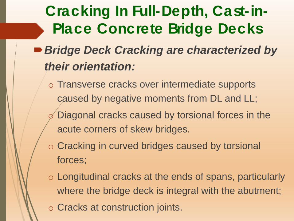
Cracking In Full-Depth, Cast-in-Place Concrete Bridge Decks
Bridge Deck Cracking are characterized by their orientation: o Transverse cracks over intermediate supports
caused by negative moments from DL and LL;
o Diagonal cracks caused by torsional forces in the acute corners of skew bridges.
o Cracking in curved bridges caused by torsional forces;
o Longitudinal cracks at the ends of spans, particularly where the bridge deck is integral with the abutment;
o Cracks at construction joints.
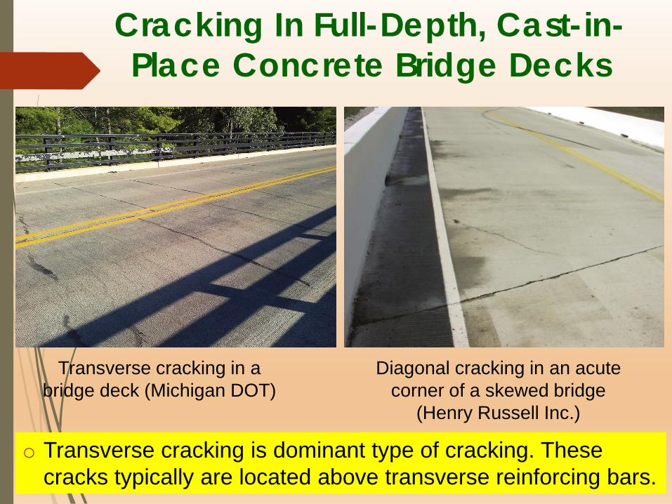
Cracking In Full-Depth, Cast-in-Place Concrete Bridge Decks
Transverse cracking in a bridge deck (Michigan DOT)
Diagonal cracking in an acute corner of a skewed bridge
(Henry Russell Inc.)
o Transverse cracking is dominant type of cracking. These cracks typically are located above transverse reinforcing bars.
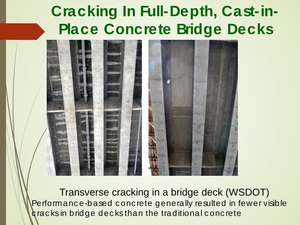
Cracking In Full-Depth, Cast-in-Place Concrete Bridge Decks
Transverse cracking in a bridge deck (WSDOT) Performance-based concrete generally resulted in fewer visible cracks in bridge decks than the traditional concrete
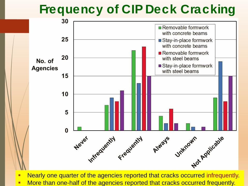
Frequency of CIP Deck Cracking
Nearly one quarter of the agencies reported that cracks occurred infrequently. More than one-half of the agencies reported that cracks occurred frequently.

Partial-Depth, Precast Concrete Panels with a CIP Topping
This bridge deck system consists of precast concrete panels with CIP Topping to make a composite system .
The system is often used to accelerate bridge deck construction.
Frequency of cracking with partial-depth
precast concrete panels.
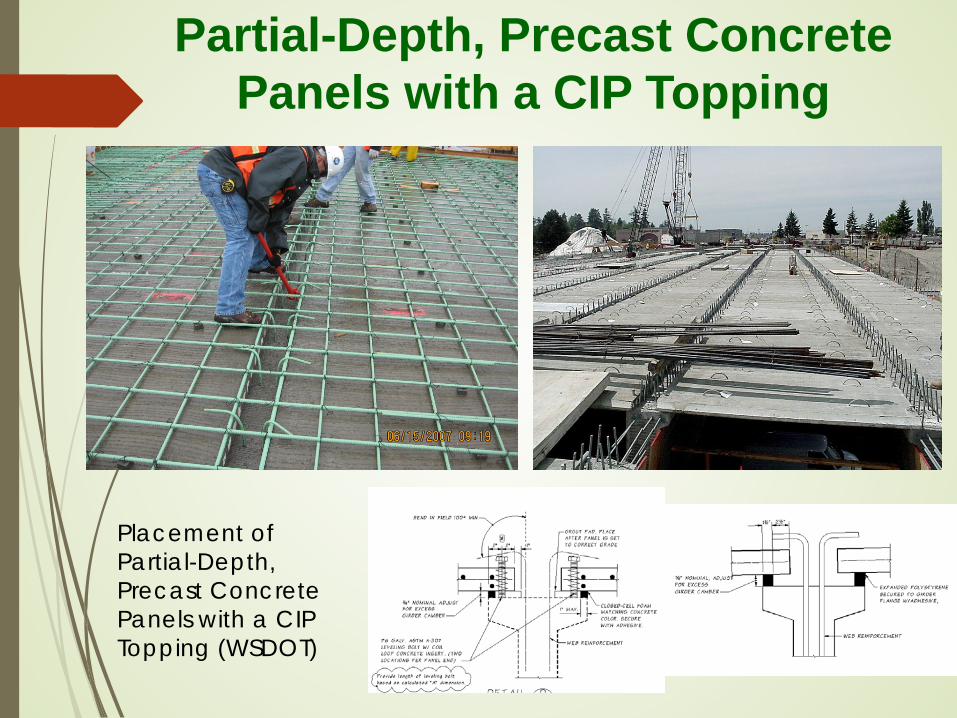
Partial-Depth, Precast Concrete Panels with a CIP Topping
Placement of Partial-Depth, Precast Concrete Panels with a CIP Topping (WSDOT)
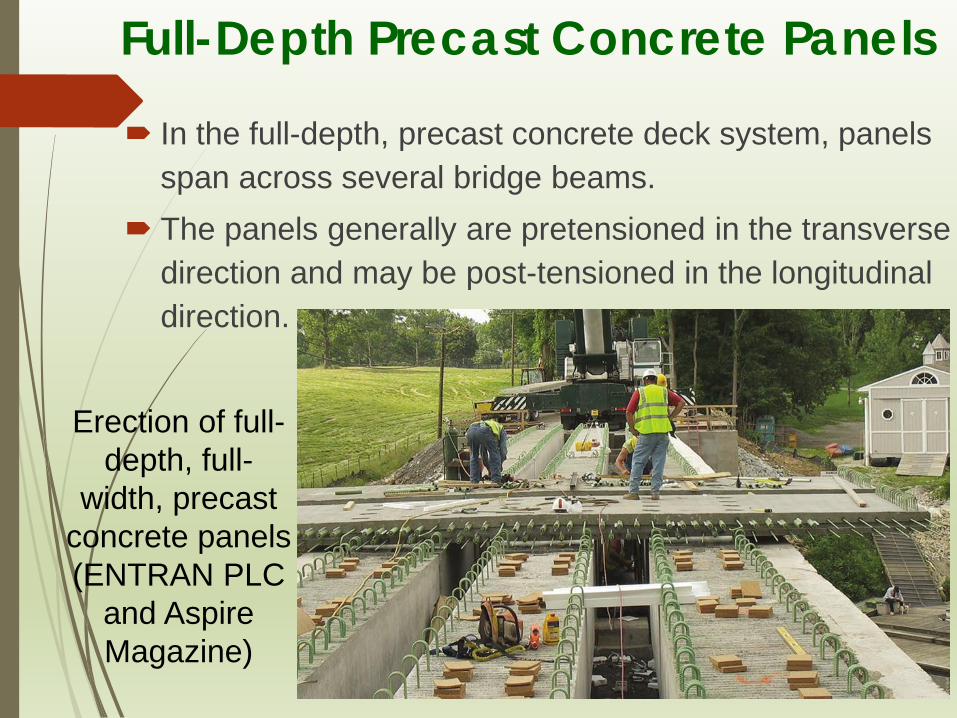
Full-Depth Precast Concrete Panels
In the full-depth, precast concrete deck system, panels span across several bridge beams.
The panels generally are pretensioned in the transverse direction and may be post-tensioned in the longitudinal direction.
Erection of full-depth, full-
width, precast concrete panels (ENTRAN PLC
and Aspire Magazine)
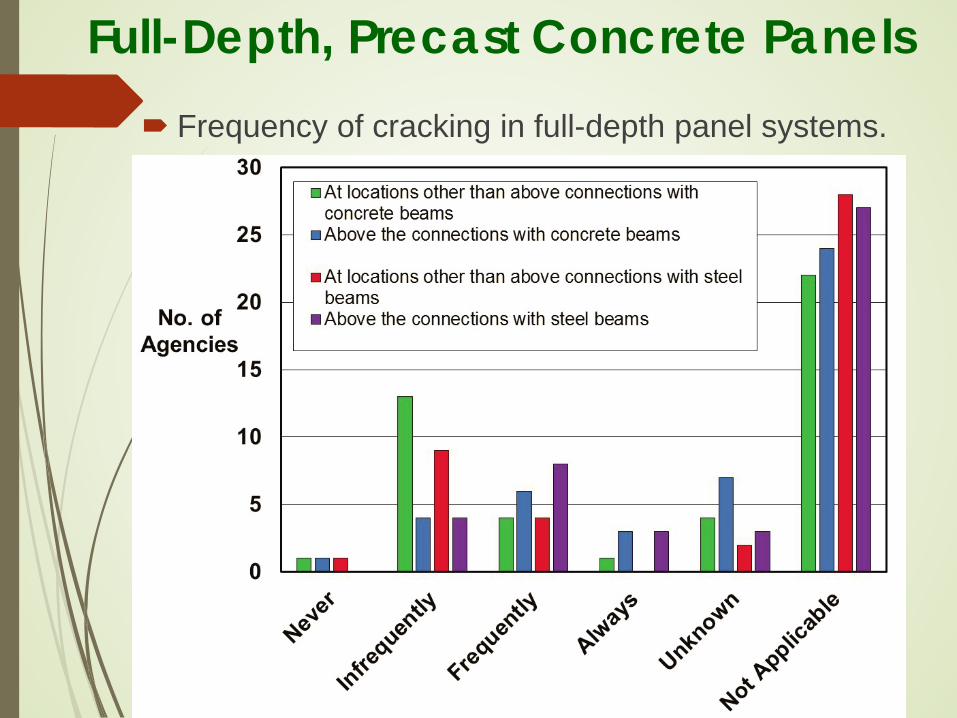
Frequency of cracking in full-depth panel systems.
Full-Depth, Precast Concrete Panels

Effect of Cement Types
The source of cement has a large effect on drying shrinkage.
Slower-setting cements can be expected to have reduced drying shrinkage and cracking.
Type III cements should be used with caution for deck applications. Some agencies restrict the use of Type III cements to precast concrete members.
In an effort to control temperatures, Type II or Type IV cements, with their lower heat of hydration, are used in lieu of Type I cement in warmer ambient conditions.
Decks constructed with Type II cement cracked less than did those constructed with Type I cement.

Shrinkage compensating concrete: A shrinkage-compensating concrete is an expansive
cement that causes the concrete to expand during the first few days.
Slag: Use of slag reduced the free shrinkage compared with
mixtures containing only cement. Combination of slag cement with a porous limestone
coarse aggregate results in an even greater reduction in free shrinkage.
Silica Fume: Concretes containing silica fume had higher
shrinkages at early ages than other concretes.
Effect of Supplementary Cementitious Materials

Effect of Water-Cementitious Materials Ratio
The most important factor affecting drying shrinkage is the amount of water per unit volume of concrete.
Only about half of the water is used in the hydration process. The rest is to provide workability and finishability.
The excess free water that remains in the hardened concrete contributes to the drying shrinkage. Thus, shrinkage can be minimized by keeping the water content as low as possible.
Limit the water-cement ratio to a maximum of 0.40.
Others recommended the use of a water-cement ratio between 0.40 and 0.45 and a cement of 650 to 660 lb/yd3.

Use of Fibers in Bridge Decks
Fiber-Reinforced Concrete classifies into four different categories based on the material type of fiber: steel, glass, synthetic, and natural.
Fibers are beneficial in reducing bleeding and plastic settlement cracking in fresh concrete and increasing energy absorption and load-carrying capacity after cracking.
Several states now require the use of fibers in bridge decks:
o Use of synthetic fibers in all bridge deck concrete, with quantity per manufacturer’s recommendations.
o Use of polymer fibers of at least 1 lb of polymer microfibers (length of 0.5 to 2 in), and at least 3 lb of macrofibers (length of 1.0 to 2.5 in) per cubic yard of deck concrete.
Internal Curing of Deck Concrete
Internal curing is “a process by which the hydration of cement continues because of the availability of internal water that is not part of the mixing water”. Internally cured concrete uses absorptive materials
in the mixture that supplement standard curing practices by supplying moisture to the interior of the concrete. This adds moisture without affecting the w/cm ratio.
LWA for internal curing is often used.
Internal curing has been used in many bridges.
Self-Consolidating Concrete (SCC)
SCC is a highly flowable nonsegregating concrete made with conventional concrete materials except that a viscosity-modifying admixture may be included. SCC has been used in the construction of precast
beams, precast deck panels, and connections. SCC can be prone to plastic shrinkage cracking
because the mixtures exhibit little surface bleeding. The increased paste volume in SCC creates a
potential for increased drying shrinkage.
Use of SCC in CIP decks is limited because the concrete tends to flow downhill, making it difficult to cast sloping elements.
Effects of Curing Practices on Concrete Cracking
Curing Practices – Survey: Range of curing periods if often from 3 to 14 days,
the most frequent time period being 7 days. Percentage of agencies specifying 7 days or fewer
decreased from 87% to 67%, and the percentage specifying 14 days increased from 11% to 24%.
Only two states reported fewer than 7 days of wet curing.
Apply moist curing immediately after concrete
finishing and maintain continuously with curing compound applied thereafter.
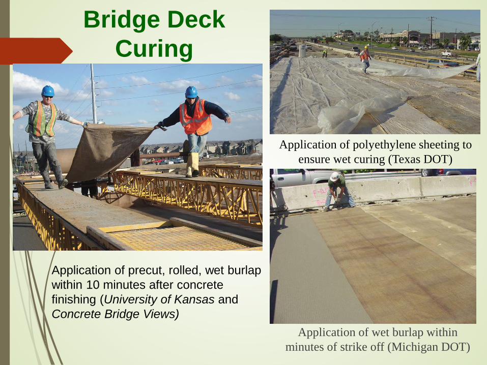
Application of wet burlap within minutes of strike off (Michigan DOT)
Application of polyethylene sheeting to ensure wet curing (Texas DOT)
Bridge Deck Curing
Application of precut, rolled, wet burlap within 10 minutes after concrete finishing (University of Kansas and Concrete Bridge Views)
Effects of Curing Practices on Concrete Cracking
Curing Practices: Plastic shrinkage cracks occur when moisture is removed from the
surface at a faster rate than it is replaced by bleed water.
The rate of evaporation depends on the air and concrete temperatures, relative humidity, and wind speed.
If the rate of evaporation approaches 0.2 lb/ft2/h, precautions against plastic shrinkage cracking are needed.
Plastic shrinkage cracking can be minimized by taking precautionary methods such as fog spraying.
The most effective curing is to keep the concrete continuously wet with a wet cover for at least 7 to 14 days.
Shrinkage cracking in hardened concrete can be prevented by using a curing compound after water curing.
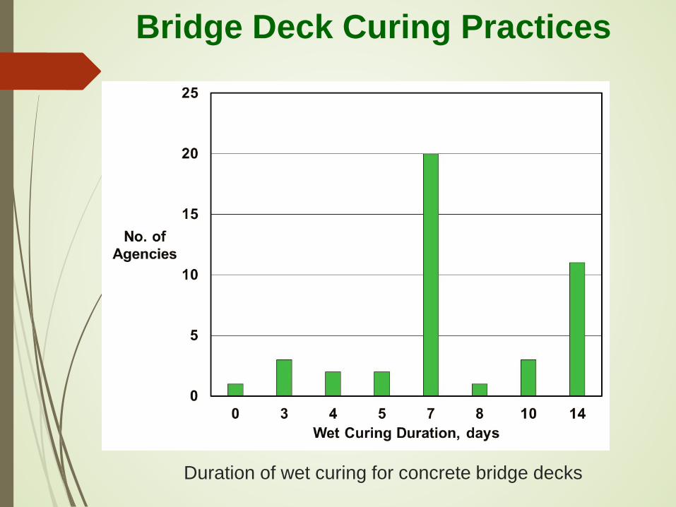
Bridge Deck Curing Practices
Duration of wet curing for concrete bridge decks

Weather Conditions affecting Curing
Factors Affecting Deck Curing: Weather conditions, such as high temperatures
and low humidity, and inadequate curing.
Concrete placement shall cease or protective measures be taken during periods of high evaporation.
Casting concrete decks at night significantly reduced deck cracking.
Increased in wind speed affects the manual fogging operation, making it difficult to keep up with the rate of evaporation.
Fiber-Reinforced Polymer Reinforcement
Fiber-reinforced polymer (FRP) reinforcement consists of a continuous fiber, such as glass, carbon, or aramid, embedded in a resin matrix, such as epoxy, polyester, vinylester, or phenolics.
The advantages of FRP is that it does not corrode and is lighter to ship and install than is steel reinforcement.
The use of FRP was reported beneficial in reducing deck cracking.
Deck constructed with GFRP bars as the top mat showed no differences in the behavior of the deck after 1 year of service, and there was no visible cracking.
Role Of Cracks In Corrosion of Reinforcing Steel
Effect of Cracking: Viewpoints and Facts: Cracks permit deeper and rapid penetration of
chloride ions, moisture, and oxygen. The chloride ions penetrate concrete resulting in
corrosion. Cracks perpendicular to reinforcing bars accelerate
corrosion of the reinforcement. Cracks that follow the line of a reinforcing bar are
more serious because the length of the bar exposed to the moisture, oxygen, and chlorides.
Crack widths of less than 0.01 in. have little effect. Wider cracks may accelerate corrosion over several years
Effect of Reinforcement Types The service life of a bridge deck containing epoxy-
coated reinf is estimated to be approximately 86 years.
The trend for bridge decks with stainless steel reinf is slightly better in the early stages than the trend for bridge decks with epoxy-coated reinforcement.
The trend for bridge decks with FRP reinforcement is not as good in the early years as the trend for bridge decks with epoxy-coated reinforcement. This is attributed to the lower modulus of elasticity of the FRP reinforcement, which may be resulting in increased cracking of the bridge deck surface.
Effect of Reinforcement Type
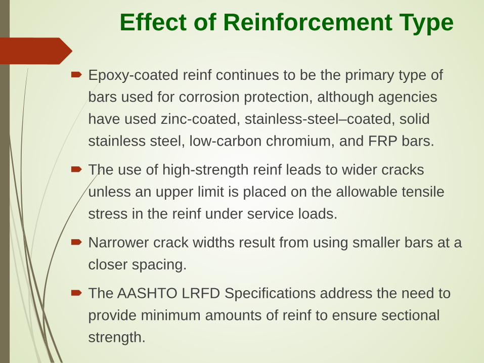
Epoxy-coated reinf continues to be the primary type of bars used for corrosion protection, although agencies have used zinc-coated, stainless-steel–coated, solid stainless steel, low-carbon chromium, and FRP bars.
The use of high-strength reinf leads to wider cracks unless an upper limit is placed on the allowable tensile stress in the reinf under service loads.
Narrower crack widths result from using smaller bars at a closer spacing.
The AASHTO LRFD Specifications address the need to provide minimum amounts of reinf to ensure sectional strength.

Two methods for concrete bridge deck design are provided in Section 9 of the LRFD Specifications:
The empirical method of Article 9.7.2: o Is based on the concept that primary action is internal arching.
o It requires that four layers of reinforcement.
o The minimum amount of reinforcement is 0.27 in.2/ft for each bottom layer and 0.18 in.2/ft for each top layer.
The traditional method of Article 9.7.3: o Is based on the assumption that the primary action is flexural.
o Four layers of reinforcement are required, with transverse reinf at a percentage of the amount of primary reinforcement.
o Checking of bar spacing to control flexural crack widths per Article 5.6.7 is required.
Specifications for Crack Control
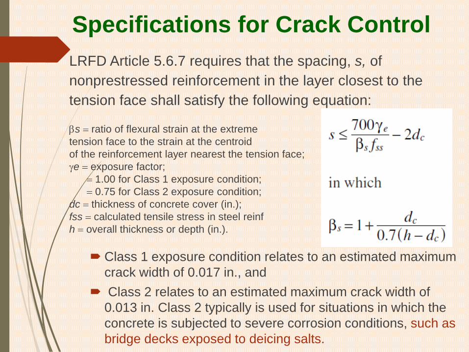
LRFD Article 5.6.7 requires that the spacing, s, of nonprestressed reinforcement in the layer closest to the tension face shall satisfy the following equation:
βs = ratio of flexural strain at the extreme tension face to the strain at the centroid of the reinforcement layer nearest the tension face; γe = exposure factor;
= 1.00 for Class 1 exposure condition; = 0.75 for Class 2 exposure condition;
dc = thickness of concrete cover (in.); fss = calculated tensile stress in steel reinf h = overall thickness or depth (in.).
Class 1 exposure condition relates to an estimated maximum crack width of 0.017 in., and
Class 2 relates to an estimated maximum crack width of 0.013 in. Class 2 typically is used for situations in which the concrete is subjected to severe corrosion conditions, such as bridge decks exposed to deicing salts.
Specifications for Crack Control
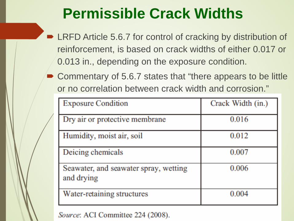
Permissible Crack Widths LRFD Article 5.6.7 for control of cracking by distribution of
reinforcement, is based on crack widths of either 0.017 or 0.013 in., depending on the exposure condition.
Commentary of 5.6.7 states that “there appears to be little or no correlation between crack width and corrosion.”
Determination of Bar Spacing to Control Crack Widths
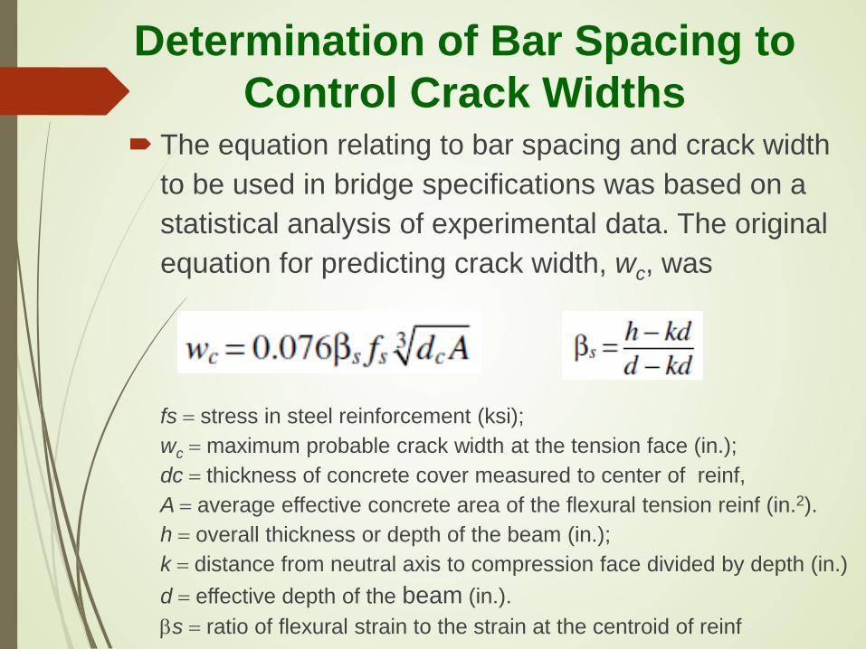
The equation relating to bar spacing and crack width to be used in bridge specifications was based on a statistical analysis of experimental data. The original equation for predicting crack width, wc, was fs = stress in steel reinforcement (ksi); wc = maximum probable crack width at the tension face (in.); dc = thickness of concrete cover measured to center of reinf, A = average effective concrete area of the flexural tension reinf (in.2). h = overall thickness or depth of the beam (in.); k = distance from neutral axis to compression face divided by depth (in.) d = effective depth of the beam (in.). βs = ratio of flexural strain to the strain at the centroid of reinf

The AASHTO STD and the subsequent 1994 LRFD Specs included the crack width equation in terms of allowable stress in a slightly rearranged form.
The crack width variable and the βs factor were consolidated into a single Z-factor, using an approximate limiting crack width of 0.016 in. and an average βs factor of 1.2 resulted in fsa = allowable reinforcement stress (ksi); Z = factor = 170 for moderate exposure conditions
= 130 for severe exposure conditions
Determination of Bar Spacing to Control Crack Widths

Crack widths with FRP reinforcement
The modified version of the Frosch equation could be used to calculate maximum probable crack width:
wcu = maximum probable crack width for FRP reinforcement (in.); ff = stress in FRP reinforcement (ksi); Ef = modulus of elasticity of FRP reinforcing bars (ksi); βs = ratio of distance between the neutral axis and tension face to the distance between the neutral axis and the centroid of the reinforcement; dc = thickness of concrete cover measured from extreme tension fiber to center of the flexural reinforcement located closest thereto (in.); and s = spacing of reinforcement in the layer closest to the tension face (in.). kb = bond quality coefficient;
kb could vary from 0.60 to 1.72, depending on the surface characteristics of the bar. A value of 1.4 was recommended in instances in which the actual value is unknown.

LRFD Specifications for Durability LRFD Article 5.14 addresses durability of concrete structures. The principal aim is the prevention of corrosion of the
reinforcing steel. The design considerations for durability include concrete
quality, protective coatings, minimum cover, distribution and size of reinforcement, details, and crack widths.
Reinforcement prone to corrosion used in concrete exposed to deicing salts or saltwater shall be protected by the use of low-permeability concrete and concrete cover.
The effects of salt intrusion and depassivation caused by carbonation can be mitigated by using corrosion inhibitors, coated reinforcement, bimetallic reinf, stainless steel reinf, or nonmetallic reinf, such as FRP composites.
Bridge Service Life
Service life for bridges is defined by AASHTO as the period of time the bridge is expected to be in operation.
At the present time, there are no U.S. standards or guidelines in place to establish performance criteria for service life design. However, this may change in the future as a result of an AASHTO and FHWA program to promote the use of service life design.
If service lives of 100 years are considered with any degree of reliability, analytical models or design procedures that include the presence of cracks in the concrete are needed.
Bridge Service Life
Major factor that can limit the service life of a bridge is corrosion of steel reinforcement caused by deicing chemicals or saltwater.
Prediction of service life based on corrosion of reinforcement is based on a two-part model:
o Initiation phase: during which chloride ions build up at the level of reinforcement until a critical concentration is reached.
o Propagation phase, during which the reinforcement corrodes.
Practices to reduce Deck cracking: Decrease the volume of water and cementitious paste. Use the largest practical maximum size aggregate. Use aggregates that result in a lower shrinkage. Use smallest transverse bar size and minimize
spacing. Avoid high concrete compressive strengths. Design the concrete mix to produce a low modulus of
elasticity and high creep. Implement surface evaporation requirements and use
windbreaks and fogging equipment. Minimize surface evaporation from fresh concrete.
Summary of Practices to Reduce Deck Cracking

Practices to Reduce Deck Cracking
Specifications Changes that could reduce early-age cracking:
Replace the minimum cement content of 675 lb/yd3 with a maximum cement content of 600 lb/yd3.
Specify a maximum paste content of 27% by volume.
Specify a min compressive strength of 3.5 ksi at 28 days.
Consider a max comp strength of 4.5 ksi at 7 or 14 days.
Reduce max shrinkage from 0.045% to 0.035% at 28 days
Specify an air content of 6% to 8% irrespective of exposure
Avoid the use of silica fume.
Wet cure the deck for 14 days.
Apply a curing membrane after the wet curing period.

Recommended practices for reducing cracking from temperature differences are:
Minimizing the temperature difference between the CIP concrete deck and the supporting beams.
Specifying and ensuring minimum and maximum concrete temperatures at time of placement of 55°F and 75°F, respectively.
Minimizing cement content. Using a Type II cement. Using aggregates with low modulus of elasticity,
low coefficient of thermal expansion, and high thermal conductivity.
Full-Depth, Cast-in-Place Concrete Bridge Decks
Recommended design practices that can reduce and control of cracking are:
Specifying the lowest acceptable concrete compressive strength.
Specifying a minimum shrinkage of 300 to 350 millionths after 28 days of drying when tested in accordance with AASHTO T 160.
Specifying a placement sequence that will minimize tensile stresses in previously placed concrete.
Using the minimum bar sizes and spacings to control crack widths.
Full-Depth, Cast-in-Place Concrete Bridge Decks
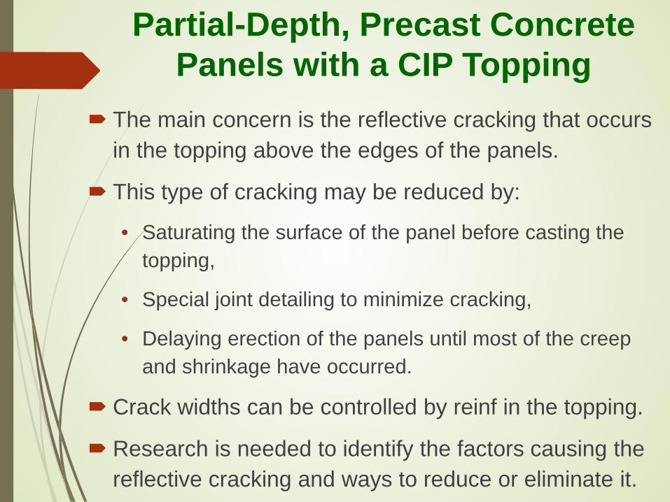
Partial-Depth, Precast Concrete Panels with a CIP Topping
The main concern is the reflective cracking that occurs in the topping above the edges of the panels.
This type of cracking may be reduced by:
• Saturating the surface of the panel before casting the topping,
• Special joint detailing to minimize cracking,
• Delaying erection of the panels until most of the creep and shrinkage have occurred.
Crack widths can be controlled by reinf in the topping.
Research is needed to identify the factors causing the reflective cracking and ways to reduce or eliminate it.
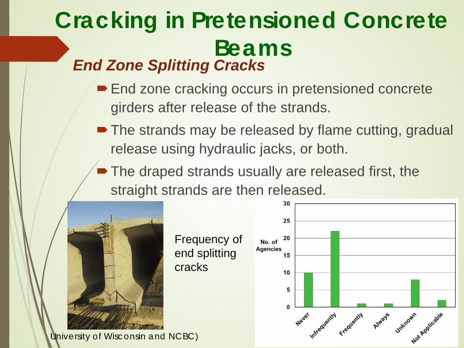
Cracking in Pretensioned Concrete Beams
End Zone Splitting Cracks End zone cracking occurs in pretensioned concrete
girders after release of the strands. The strands may be released by flame cutting, gradual
release using hydraulic jacks, or both. The draped strands usually are released first, the
straight strands are then released.
Frequency of end splitting cracks
University of Wisconsin and NCBC)

Crack Types at the End Zone of Precast Beams: 1. Vertical end cracks: Vertical face of the bottom flange
within a few inches of the end of the beam. 2. Radial cracks: Radial pattern that extends over the full
depth of the web at the end of the beam. 3. Angular cracks: Originate in the sloped part of the
bottom flange a few inches away from the end of the beam, propagate upward at an angle toward the web.
4. Strand cracks: Originate at the end of the prestressing strand and propagate to the outer surface of the beam.
5. Horizontal top flange cracks: Begin at the end face of the upper flange and move inward.
6. Horizontal web cracks: Begins at the end of the beam and extend a short distance into the beam.
End Zone Splitting Cracks
Possible Causes For End Zone Cracking: Method of detensioning: flame cut or hydraulic. Release of draped strands before the bottom strands. Order of release of bottom strands with flame cutting. Length of free strand in the prestressing bed. Friction between the beam end and prestressing bed. Heat concentration from flame cutting. Debonded strands Inadequate design of end zone reinforcement. Concrete type: lightweight or normal weight. Strand distribution: draped or straight. Lifting the beam from the bed.
End Zone Splitting Cracks

End Zone Splitting Cracks
Cracking at the ends of pretensioned girders occur more frequently in girders with draped strands.
The following equation was proposed to control the size of these cracks:
At = total area of stirrups required (in.2); T = effective prestressing force (kip); fs = max allowable stress in stirrups (ksi); h = overall depth of the girder (in.); and lt = strand transfer length (in.).
If h/lt is taken as 2, the equation reduces to designing for about 4% of the prestressing force, which is the amount of splitting reinforcement required by LRFD
Methods Reducing the End zone cracking in pretensioned beams:
Modifying the detensioning sequence. Cut some of the bottom straight strands before all
of the draped strands. Precut one pair of straight strands for every three pairs of draped strands.
Cut the bottom straight strands in alternating from the CL of the cross section. The outer strands should not be the last to be released.
Where debonding is used, cut a few straight strands first.
Proper use of splitting and confinement reinforcement in the end zone region.
End Zone Splitting Cracks
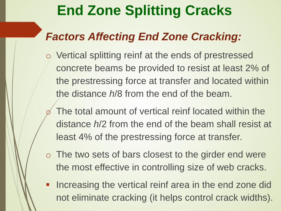
Factors Affecting End Zone Cracking: o Vertical splitting reinf at the ends of prestressed
concrete beams be provided to resist at least 2% of the prestressing force at transfer and located within the distance h/8 from the end of the beam.
o The total amount of vertical reinf located within the distance h/2 from the end of the beam shall resist at least 4% of the prestressing force at transfer.
o The two sets of bars closest to the girder end were the most effective in controlling size of web cracks.
Increasing the vertical reinf area in the end zone did not eliminate cracking (it helps control crack widths).
End Zone Splitting Cracks

Crack width limits for acceptance, repair, or rejection of beams with web splitting cracks: Cracks narrower than 0.012 in. may be left
unrepaired. Cracks ranging in width from 0.012 to 0.025 in.
o should be repaired by filling the cracks and coating the end 4 ft with an approved sealant.
Cracks ranging in width from 0.025 to 0.050 in. o should be filled by epoxy injection and the end 4 ft
of the beam web coated with an approved sealant. Cracks wider that 0.050 in.
o should be rejected unless shown that structural capacity and long-term durability are sufficient.
End Zone Splitting Cracks
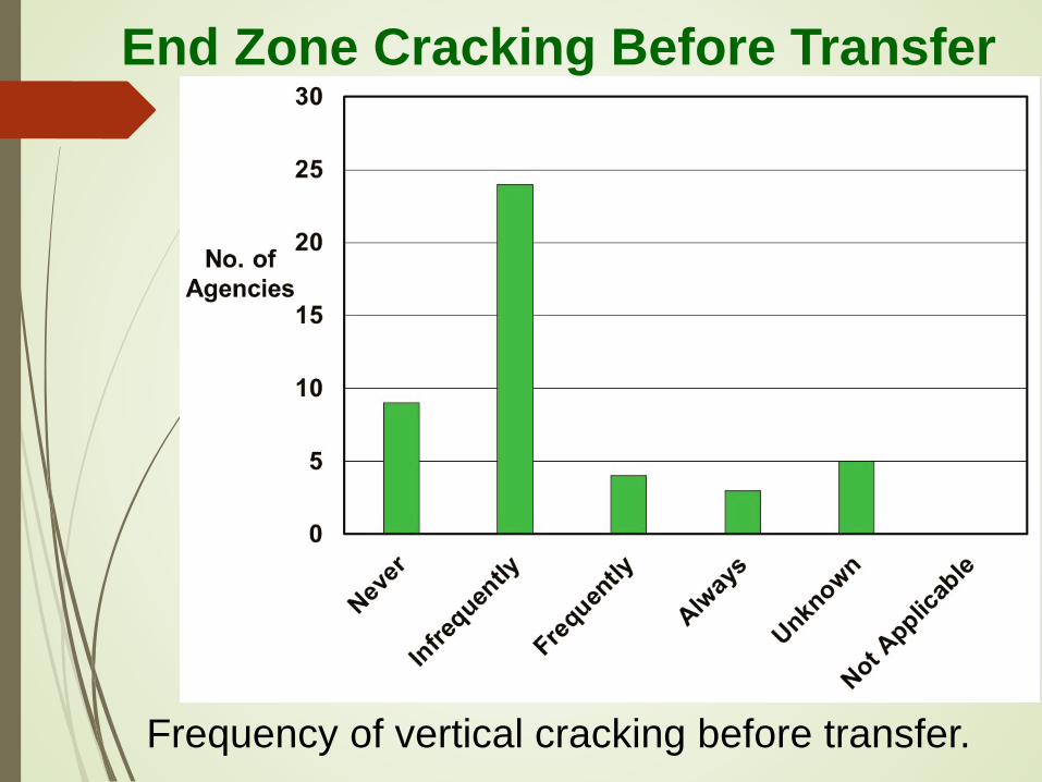
Frequency of vertical cracking before transfer.
End Zone Cracking Before Transfer
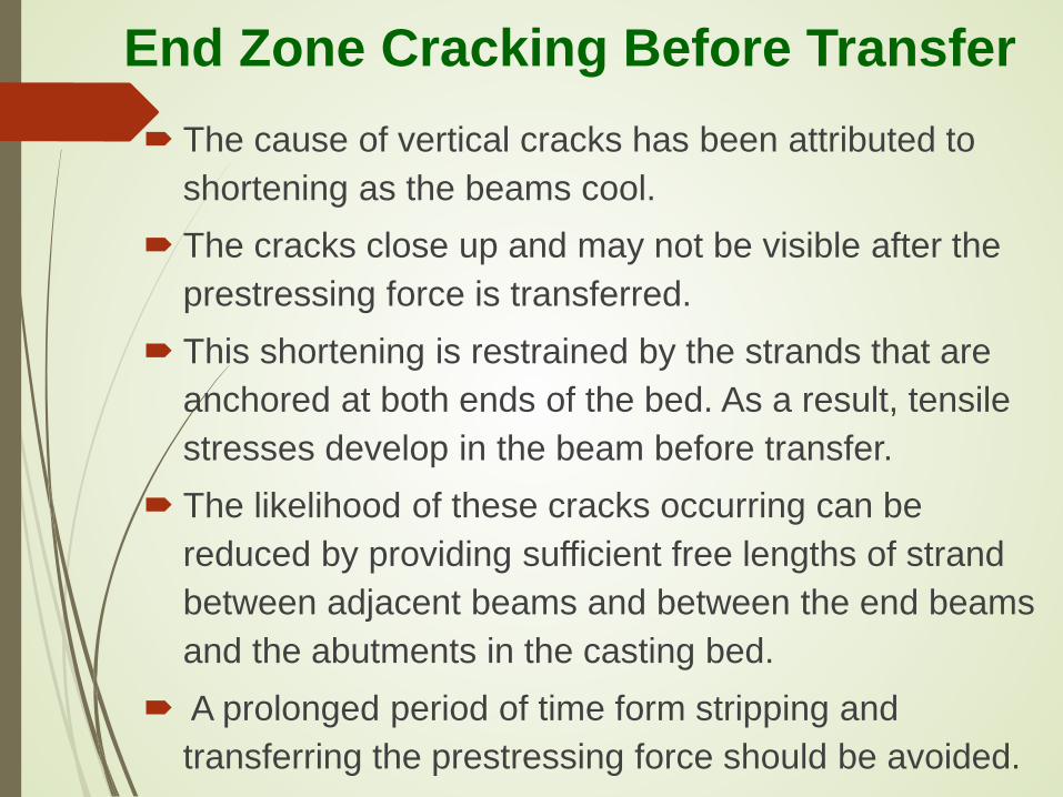
The cause of vertical cracks has been attributed to shortening as the beams cool.
The cracks close up and may not be visible after the prestressing force is transferred.
This shortening is restrained by the strands that are anchored at both ends of the bed. As a result, tensile stresses develop in the beam before transfer.
The likelihood of these cracks occurring can be reduced by providing sufficient free lengths of strand between adjacent beams and between the end beams and the abutments in the casting bed.
A prolonged period of time form stripping and transferring the prestressing force should be avoided.
End Zone Cracking Before Transfer
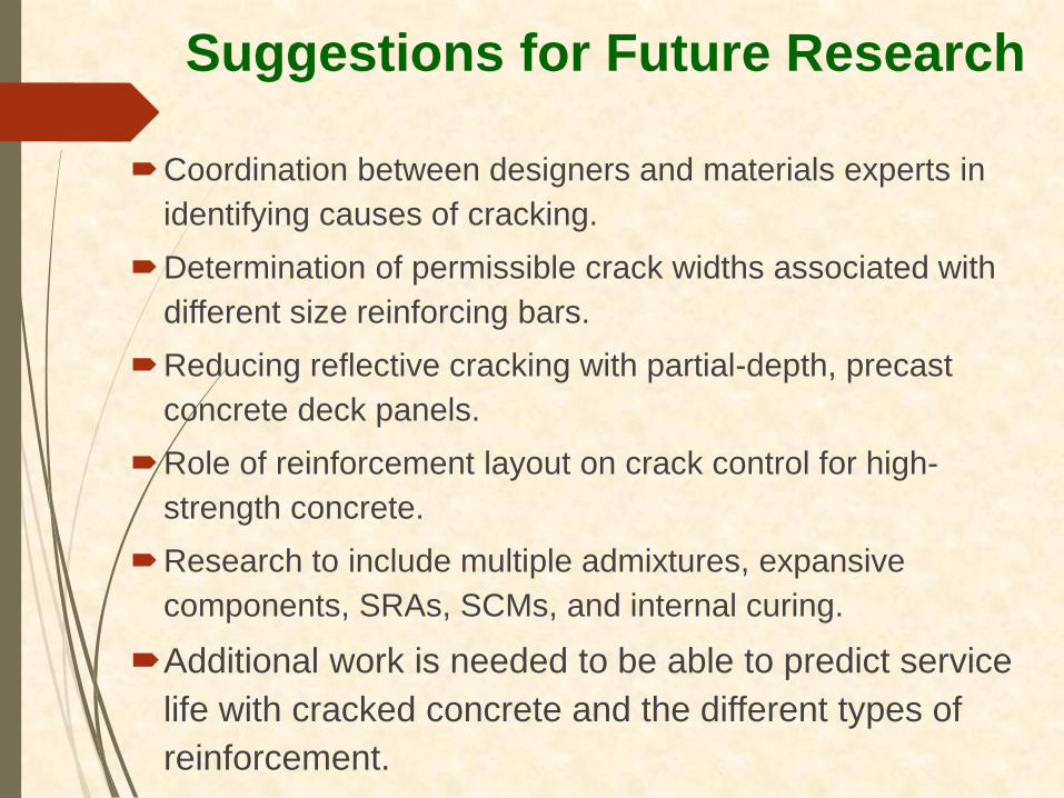
Coordination between designers and materials experts in identifying causes of cracking.
Determination of permissible crack widths associated with different size reinforcing bars.
Reducing reflective cracking with partial-depth, precast concrete deck panels.
Role of reinforcement layout on crack control for high-strength concrete.
Research to include multiple admixtures, expansive components, SRAs, SCMs, and internal curing.
Additional work is needed to be able to predict service life with cracked concrete and the different types of reinforcement.
Suggestions for Future Research
Conclusions
Concrete cracking in bridges is complex and unlikely to be caused by a single effect. In some situations, cracking cannot be avoided.
Nevertheless, crack quantities and widths can be minimized by the careful selection of materials, proper reinforcement design details, and appropriate construction practices.
Control of Concrete Cracking in Bridges
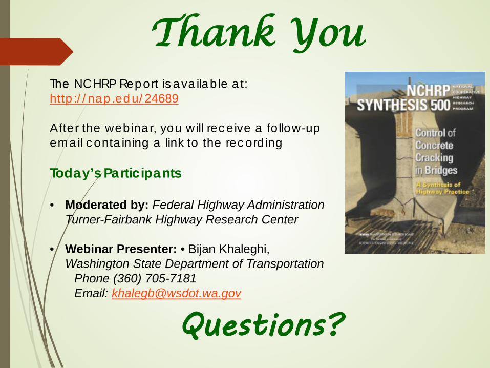
The NCHRP Report is available at: http://nap.edu/24689 After the webinar, you will receive a follow-up email containing a link to the recording Today’s Participants • Moderated by: Federal Highway Administration
Turner-Fairbank Highway Research Center
• Webinar Presenter: • Bijan Khaleghi, Washington State Department of Transportation
Phone (360) 705-7181 Email: [email protected]
Thank You
Questions?
Today’s Participants
• Ben Graybeal – Federal Highway Administration Turner-Fairbank Research
Center, [email protected] • Bijan Khaleghi
– Washington State Department of Transportation, [email protected]
Get Involved with TRB • Getting involved is free! • Join a Standing Committee (http://bit.ly/2jYRrF6) • Become a Friend of a Committee
(http://bit.ly/TRBcommittees) – Networking opportunities – May provide a path to become a Standing Committee
member • For more information: www.mytrb.org
– Create your account – Update your profile 97th TRB Annual Meeting: January 7-11, 2018

Get involved with NCHRP
• Suggest NCHRP research topics • Volunteer to serve on NCHRP panels • Lead pilot projects and other
implementation efforts at your agency • For more information:
http://www.trb.org/nchrp/nchrp.aspx