224r-01 control of cracking in concrete structurescivilwares.free.fr/aci/mcp04/224r_01.pdfcontrol of...
TRANSCRIPT
Control of Cracking in Concrete Structures
ACI 224R-01
Reported by ACI Committee 224
Mohamed Abou-Zeid David W. Fowler* Edward G. Nawy*
John H. Allen Grant T. Halvorsen Randall W. Poston*
James P. Barlow Will Hansen* Royce J. Rhoads
Merle E. Brander* M. Nadim Hassoun Andrew Scanlon
Kathy Carlson Harvey Haynes* Ernest K. Schrader*
David Darwin* Paul Hedli Wimal Suaris*
Fouad H. Fouad* Tony C. Liu Zenon A. Zielinski
Florian BarthChairman
Robert J. Frosch*
Secretary
*Members of ACI 224 who assisted in revisions to this report.
ACI Committee Reports, Guides, Standard Practices,and Commentaries are intended for guidance in planning,designing, executing, and inspecting construction. Thisdocument is intended for the use of individuals who arecompetent to evaluate the significance and limitations ofits content and recommendations and who will accept re-sponsibility for the application of the material it contains.The American Concrete Institute disclaims any and all re-sponsibility for the stated principles. The Institute shallnot be liable for any loss or damage arising therefrom.
Reference to this document shall not be made in con-tract documents. If items found in this document are de-sired by the Architect/Engineer to be a part of the contractdocuments, they shall be restated in mandatory languagefor incorporation by the Architect/Engineer.
The principal causes of cracking and recommended crack-control proce-
dures are presented. The current state of knowledge in microcracking and
fracture of concrete is reviewed. The control of cracking due to drying
shrinkage and crack control in flexural members, overlays, and mass con-
crete construction are covered in detail. Long-term effects on cracking are
considered and crack-control procedures used in construction are pre-
sented. Information is presented to assist in the development of practical
and effective crack-control programs for concrete structures. Extensive ref-
erences are provided.
Keywords: aggregates; anchorage (structural); bridge decks; cement-
aggregate reactions; concrete construction; concrete pavements; concrete
slabs; cooling; corrosion; crack propagation; cracking (fracturing); crackwidth and spacing; drying shrinkage; shrinkage-compensating concrete;
heat of hydration; mass concrete; microcracking; polymer-modified concrete;prestressed concrete; reinforced concrete; restraint; shrinkage; temperature;
tensile stresses; thermal expansion; volume change.
224
ACI 224R-01 supersedes ACI 224R-90 and became effective May 16, 2001.Copyright 2001, American Concrete Institute.All rights reserved including rights of reproduction and use in any form or by any
means, including the making of copies by any photo process, or by electronic ormechanical device, printed, written, or oral, or recording for sound or visual reproduc-tion or for use in any knowledge or retrieval system or device, unless permission inwriting is obtained from the copyright proprietors.
CONTENTSChapter 1—Introduction, p. 224R-2
Chapter 2—Crack mechanisms in concrete, p. 224R-2
2.1—Introduction2.2—Compressive microcracking2.3—Fracture
Chapter 3—Control of cracking due to drying shrinkage, p. 224R-11
3.1—Introduction3.2—Cause of cracking due to drying shrinkage3.3—Drying shrinkage3.4—Factors controlling drying shrinkage of concrete3.5—Control of shrinkage cracking3.6—Shrinkage-compensating concrete
Chapter 4—Control of cracking in flexural members, p. 224R-17
4.1—Introduction4.2—Crack-control equations for reinforced concrete beams4.3—Crack control in two-way slabs and plates4.4—Tolerable crack widths versus exposure conditions inreinforced concrete4.5—Flexural cracking in prestressed concrete4.6—Anchorage-zone cracking in prestressed concrete4.7—Crack control in deep beams4.8—Tension cracking
R-1
224R-2 ACI COMMITTEE REPORT
Chapter 5—Long-term effects on cracking, p. 224R-24
5.1—Introduction5.2—Effects of long-term loading5.3—Environmental effects5.4—Aggregate and other effects5.5—Use of polymers in improving cracking characteristics
Chapter 6—Control of cracking in overlays,p. 224R-25
6.1—Introduction6.2—Fiber-reinforced concrete (FRC) overlays6.3—Latex- and epoxy-modified concrete overlays6.4—Polymer-impregnated concrete (PIC) systems6.5—Epoxy and other polymer concrete overlays
Chapter 7—Control of cracking in mass concrete, p. 224R-28
7.1—Introduction7.2—Methods of crack control7.3—Design7.4—Construction7.5—Operation
Chapter 8—Control of cracking by proper construction practices, p. 224R-34
8.1—Introduction8.2—Restraint8.3—Shrinkage8.4—Settlement8.5—Construction8.6—Specifications to minimize drying shrinkage8.7—Conclusion
Chapter 9—References, p. 224R-399.1—Referenced standards and reports9.2—Cited references9.3—Other references
CHAPTER 1—INTRODUCTIONCracks in concrete structures can indicate major structural
problems and detract from the appearance of monolithicconstruction. There are many specific causes of cracking.
This report presents the principal causes of cracking and adetailed discussion of crack-control procedures. The reportconsists of eight chapters designed to help the engineer andthe contractor in developing crack-control measures.
This report is an update of previous committee reports(ACI Committee 224 1972, 1980, 1990). ACI Bibliogra-phy No. 9 supplemented the original ACI 224R (1971). TheCommittee has also prepared reports on the causes, evaluation,and repair of cracking, ACI 224.1R; cracking of concrete in di-rect tension, ACI 224.2R; and joints in concrete construction,ACI 224.3R.
In this revision of the report, Chapter 2 on crack mechanisms
CHAPTER 2—CRACK MECHANISMS IN CONCRETE
2.1—IntroductionCracking plays an important role in concrete’s response to
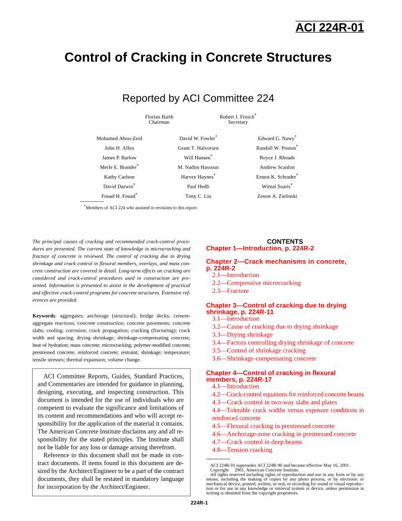
load in both tension and compression. The earliest studies ofthe microscopic behavior of concrete involved the responseof concrete to compressive stress. That early work showedthat the stress-strain response of concrete is closely associatedwith the formation of microcracks, that is, cracks that form atcoarse-aggregate boundaries (bond cracks) and propagatethrough the surrounding mortar (mortar cracks) (Hsu, Slate,Sturman, and Winter 1963; Shah and Winter 1966; Slate andMatheus 1967; Shah and Chandra 1970; Shah and Slate1968; Meyers, Slate, and Winter 1969; Darwin and Slate1970), as shown in Fig. 2.1.
has been revised extensively to reflect the interest and attentiongiven to aspects of fracture mechanics of concrete during the1980s. Chapter 3 on drying shrinkage has been rewritten.
Chapter 4 has been revised to include updated informationon crack-width predictive equations, cracking in partiallyprestressed members, anchorage zone cracking, and flexuralcracking in deep flexural members. Chapter 6 on concrete
overlays has been reorganized and revised in modest detailto account for updated information on fiber reinforcementand on polymer-modified concrete. Chapter 7 on massconcrete has been revised to consider structural consequencesmore extensively.During early microcracking studies, concrete was consideredto be made up of two linear, elastic brittle materials; cementpaste and aggregate; and microcracks were considered to bethe major cause of concrete’s nonlinear stress-strain behaviorin compression (Hsu, Slate, Sturman, and Winter 1963; Shahand Winter 1966). This picture began to change in the1970s. Cement paste is a nonlinear softening material, asis the mortar constituent of concrete. The compressive non-linearity of concrete is highly dependent upon the responseof these two materials (Spooner 1972; Spooner and Dougill1975; Spooner, Pomeroy, and Dougill 1976; Maher and Dar-win 1977; Cook and Chindaprasirt 1980; Maher and Darwin1982) and less dependent upon bond and mortar microcrackingthan originally thought. Research indicates, however, that a sig-nificant portion of the nonlinear deformation of cement pasteand mortar results from the formation of microcracks thatare several orders of magnitude smaller than those observed inthe original studies (Attiogbe and Darwin 1987, 1988). Thesesmaller microcracks have a surface density that is two tothree orders of magnitude higher than the density of bondand mortar microcracks in concrete at the same compres-sive strain, and their discovery represents a significantstep towards understanding the behavior of concrete andits constituent materials in compression.
The effect of macroscopic cracks on the performance andfailure characteristics of concrete has also received considerableattention. For many years, concrete has been considered a brittlematerial in tension. Many attempts have been made to useprinciples of fracture mechanics to model the fracture ofconcrete containing macroscopic cracks.
The field of fracture mechanics was developed by Griffith(1920) to explain the failure of brittle materials. Linear elasticfracture mechanics (LEFM) predicts the rapid propagation of amicrocrack through a homogeneous, isotropic, linear-elasticmaterial. The theory uses the stress-intensity factor K that
CONTROL OF CRACKING IN CONCRETE STRUCTURES 224R-3
Fig. 2.1—Cracking maps and stress-strain curves for concrete loaded in uniaxial compression(Shah and Slate 1968).
represents the stress field ahead of a sharp crack in a struc-tural member which is a function of the crack geometry andstress. K is further designated with subscripts, I, II, and III,depending upon the nature of the deformation at the cracktip. For a crack at which the deformation is perpendicular tothe crack plane, K is designated as KI, and failure occurswhen KI reaches a critical value KIc, known as the criticalstress-intensity factor. KIc is a measure of the fracture tough-ness of the material, which is simply a measure of the resis-tance to crack propagation. Often the region around the cracktip undergoes nonlinear deformation, such as yielding inmetals, as the crack grows. This region is referred to as theplastic zone in metals, or more generally as the fracture processzone. To properly measure KIc for a material, the test specimenshould be large enough so that the fracture process zone issmall compared with the specimen dimensions. For LEFMto be applicable, the value of KIc must be a material property,independent of the specimen geometry (as are other materialproperties, such as yield strength or compressive strength).
Initial attempts to measure KIc in concrete were unsuccessfulbecause KIc depended on the size and geometry of the testspecimens (Wittmann 1986). As a result of the heterogeneityinherent in cement paste, mortar, and concrete, these materialsexhibit a significant fracture-process zone and the criticalload is preceded by a substantial amount of slow crack growth.This precritical crack growth has been studied experimentallyby several researchers (John and Shah 1986; Swartz and Go1984; Bascoul, Kharchi, and Maso 1987; Maji and Shah1987; Castro-Montero, Shah, and Miller 1990). This researchhas provided an improved understanding of the fracture processzone and has led to the development of more rational fracturecriteria for concrete.
This chapter is divided into two sections. The first sectionon compressive microcracking presents the current knowledgeof the response of concrete and its constituent materials undercompressive loading and the role played by the various typesof microcracks in this process. The second section discussesthe applicability of both linear and nonlinear fracture mechanicsmodels to concrete. A more comprehensive treatment of thefracture of concrete can be found in ACI 446.1R.
2.2—Compressive microcrackingDuring early microcracking research, a picture devel-
oped that closely linked the formation and propagation ofmicrocracks to the load-deformation behavior of concrete.Before loading, volume changes in cement paste cause inter-facial cracks to form at the mortar-coarse aggregate bound-ary (Hsu 1963; Slate and Matheus 1967). Under short-termcompressive loads, no additional cracks form until the loadreaches about 30% of the compressive strength of the con-crete (Hsu, Slate, Sturman, and Winter 1963). Above thisvalue, additional bond cracks are initiated throughout thematrix. Bond cracking increases until the load reaches about70% of the compressive strength, at which time the microc-racks begin to propagate through the mortar. Mortar crack-ing continues at an accelerated rate, forming continuouscracks parallel to the direction of compressive load, until theconcrete is no longer able to sustain the load. The onset ofmortar cracking is related to the sustained, or long-term,compressive strength. Derucher (1978) obtained a somewhatdifferent picture of the microscopic behavior of concreteusing the scanning electron microscope (SEM). He subjecteddried concrete specimens to eccentric compressive loadingwithin the SEM. He observed that microcracks that exist

224R-4 ACI COMMITTEE REPORT
Fig. 2.2—Stress-strain curves for cement paste, mortar, and concrete; w/c = 0.5 (Martin,Darwin, and Terry 1991).
before loading are in the form of bond cracks, with exten-sions into the surrounding mortar perpendicular to the bondcracks. Under increasing compression, these bond crackswiden but do not propagate at loads as low as 15% of thestrength. At about 20% of ultimate, the bond cracks begin topropagate, and at about 30%, they begin to bridge betweenone another. The bridging is almost complete at 45% of thecompressive strength. At 75% of ultimate, mortar cracksstart to join one another and continue to do so until failure.
In general, microcracking that occurs before loading has littleeffect on the strength of compressive strength of the concrete.
In studies of high-strength concrete, Carrasquillo, Slate,and Nilson (1981) concluded that it was more appropriate toclassify cracks as simple (bond or mortar) and combined(bond and mortar) and that the formation of combinedcracks consisting of more than one mortar crack signaledunstable crack growth. They observed that the higher theconcrete strength, the higher the strain (relative to the strain atpeak stress) at which this unstable crack growth is observed.They observed less total cracking in high-strength concretethan normal-strength concrete at all stages of loading.
Work by Meyers, Slate, and Winter (1969), Shah andChandra (1970), and Ngab, Slate, and Nilson (1981) demon-strated that microcracks increase under sustained and cyclicloading. Their work indicated that the total amount of micro-cracking is a function of the total compressive strain in theconcrete and is independent of the method in which the strainis applied. Suaris and Fernando (1987) also showed that thefailure of concrete under constant amplitude cyclic loadingis closely connected with microcrack growth. Sturman, Shah,and Winter (1965) found that the total degree of microcrackingis decreased and the total strain capacity in compression isincreased when concrete is subjected to a strain gradient.
Since the early work established the existence of bond andmortar microcracks, it has been popular to attribute most, ifnot all, of the nonlinearity of concrete to the formation ofthese microscopic cracks (Hsu, Slate, Sturman, and Winter1963; Shah and Winter 1966; Testa and Stubbs 1977; Car-rasquillo, Slate, and Nixon 1981). A cause and effect rela-tionship, however, has never been established (Darwin1978). Studies by Spooner (1972), Spooner and Dougill(1975), Spooner, Pomeroy, and Dougill (1976), and Maherand Darwin (1982) indicate that the degree of microcrackingcan be taken as an indication of the level of damage ratherthan as the controlling factor in the concrete’s behavior.
Experimental work by Spooner (1972), Spooner and Dougill(1975), Spooner, Pomeroy, and Dougill (1976), and Martin,Darwin, and Terry (1991) indicates that the nonlinear compres-sive behavior of concrete is strongly influenced by the nonlinearbehavior of cement paste. As illustrated in Fig. 2.2, cementpaste under compression is not an elastic, brittle material asstated in the past, but a nonlinear material with a relatively highstrain capacity. The nonlinear behavior of cement paste can betied to damage sustained by the paste, even at very low stresses.
Using a cyclic loading procedure, Spooner (1972), Spoon-er and Dougill (1975), and Spooner, Pomeroy, and Dougill(1976) demonstrated that both paste and concrete undergo mea-surable damage at strains (0.0004) at which an increase in bondand mortar microcracking cannot be detected. The level ofdamage can be detected at low loads by using an energymethod and by a change in the initial modulus of elasticityfor each load cycle. The process of damage is continuous upto failure.
The physical nature of damage that occurs in cement paste,like that in concrete, appears to be related to cracking. Thispoint was first made by Spooner, Pomeroy, and Dougill(1976) based on volumetric strain measurements and then by
CONTROL OF CRACKING IN CONCRETE STRUCTURES 224R-5
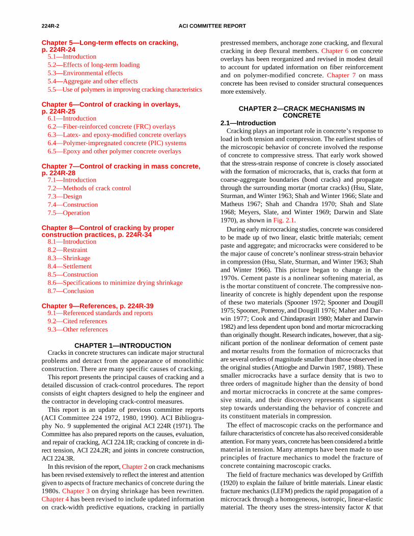
Fig 2.3—Stress-strain curves as influenced by coating aggregates (Darwin and Slate1970).
Yoshimoto et al. (1972) and Yoshimoto, Ogino, andKawakami (1976) who reported the formation of “hair-shaped” and “void-shaped” cracks in paste under flexure andcompressive loading. The relationship between nonlineardeformation and cracking in cement paste is now firmly es-tablished by the work of Attiogbe and Darwin (1987, 1988).
Studies of the stress-strain behavior of concrete under cycliccompressive load (Karsan and Jirsa 1969; Shah and Chandra1970) indicated the concrete undergoes rapid deteriorationonce the peak stress exceeds 70% of the short-term compres-sive strength of the concrete. In their study of cyclic creep,Neville and Hirst (1978) found that heat is generated evenwhen specimens are cycled below this level. They attributedthe heat to sliding at the interfacial boundary. The work ofNeville and Hirst, along with the work of Spooner, suggeststhat it can be possible that the heat measured is due to somemicroscopic sliding within the paste.
Several studies have attempted to establish the importanceof interfacial bond strength on the behavior of concrete incompression. Two studies seemed to indicate a very largeeffect, thus emphasizing the importance of interfacialstrength on concrete behavior in compression (Shah andChandra 1970; Nepper-Christensen and Nielsen 1969).These studies used relatively thick, soft coatings on coarseaggregate to reduce the bond strength. Because these softcoatings isolated the aggregate from the surrounding mortar,the effect was more like inducing a large number of voids inthe concrete matrix.
Two other studies (Darwin and Slate 1970; Perry andGillott 1977) that did not isolate the coarse aggregate fromthe mortar indicated that interfacial strength plays only a minorrole in controlling the compressive stress-strain behavior ofconcrete. Darwin and Slate (1970) used a thin coating ofpolystyrene on natural coarse aggregate. They found that alarge reduction in interfacial bond strength causes no changein the initial stiffness of concrete under short-term compressive
loads and results in about a 10% reduction in the compressivestrength, compared with similar concrete made with aggregatewith normal interfacial strength (Fig. 2.3). Darwin and Slatealso monitored microcracking. In every case, however, theaverage amount of mortar cracking was slightly greater forspecimens made with coated aggregate. This small yetconsistent difference may explain the differences in thestress-strain curves. Perry and Gillott (1977) used glassspheres with different degrees of surface roughness as coarseaggregate. Their results also indicate that reducing the inter-facial strength of the aggregate decreases the compressivestrength by about 10%.
Work by Carino (1977), using polymer-impregnatedconcrete, corroborated these last two studies. Carinofound that polymer impregnation did not increase the inter-facial bond strength but did increase the compressivestrength of concrete. He attributed the increase in strength tothe polymer’s effect on mortar strength, therefore downgradingthe importance of interfacial bond.
The importance of mortar in controlling the stress-strainbehavior of concrete is illustrated by the finite-element workof Buyukozturk (1970) and Maher and Darwin (1976, 1977).Buyukozturk (1970) used a finite-element representation ofa physical model of concrete. The model treated mortar (incompression) and aggregate (in compression and tension) aslinear elastic materials while allowing cracks to form in themortar and at mortar aggregate boundaries. Buyukozturksimulated the overall crack patterns under uniaxial loading.His finite-element model, however, could not duplicate thefull nonlinear behavior of the physical model using the for-mation of interfacial bond cracks and mortar cracks as theonly nonlinear effects. Maher and Darwin (1976, 1977) haveshown that a very close representation of the actual stress-strain behavior can be obtained using a nonlinear representationfor the mortar constituent of the physical model.
224R-6 ACI COMMITTEE REPORT
Maher and Darwin also studied the behavior of the mortarconstituent of concrete under monotonic and cyclic com-pression (1982). Degradation in mortar was shown to be acontinuous process and a function of both total strain andload history. The study indicated that residual strain as wellas the change in the initial modulus of elasticity are goodmeasures of structural change within the material. Accumu-lations of residual strain were obtained for values of maxi-mum strain as low as 0.00027. The work showed that themaximum strain alone does not control the degradation ofmortar in compression and that the total strain range (bothloading and unloading) adds to the degradation in stiffnessand accumulation of residual strain. Their work concludes aswas previously observed (Meyers, Slate, and Winter 1969;Shah and Chandra 1970; Ngab, Slate, and Nilson 1981) thatbond and mortar microcracking in concrete is a function ofthe compressive strain in the concrete and is independent ofthe method in which the strain is applied. Because the maxi-mum strain does not appear to completely control degrada-tion, factors other than bond and mortar cracks can dominatethe degradation of concrete during cyclic loading.
Martin, Darwin, and Terry (1991) studied the behavior ofpaste, mortar, and concrete under cyclic and short-term sus-tained compression. They found a great similarity in the be-havior of concrete and its mortar constituent although thebond and mortar microcracking found in concrete were notobserved in the mortar specimens. Of the three materials stud-ied, cement paste has the greatest strain capacity and strength,followed by mortar and concrete (Fig. 2.2).
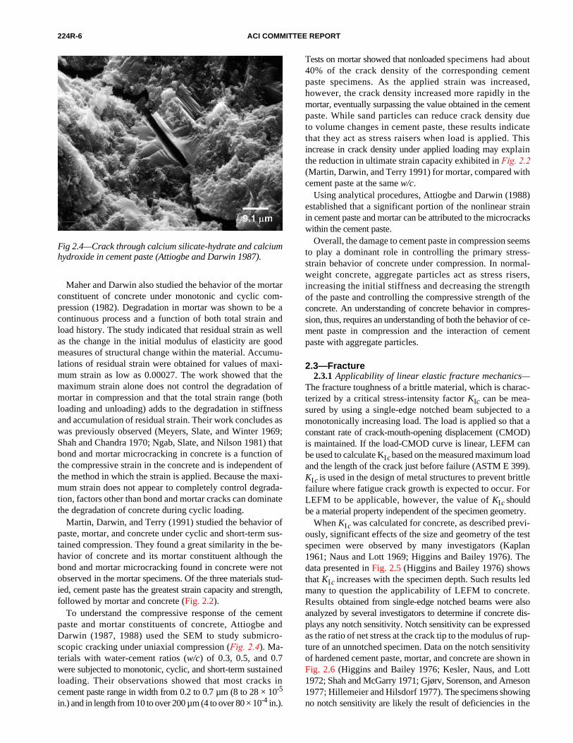
To understand the compressive response of the cementpaste and mortar constituents of concrete, Attiogbe andDarwin (1987, 1988) used the SEM to study submicro-scopic cracking under uniaxial compression (Fig. 2.4). Ma-terials with water-cement ratios (w/c) of 0.3, 0.5, and 0.7were subjected to monotonic, cyclic, and short-term sustainedloading. Their observations showed that most cracks incement paste range in width from 0.2 to 0.7 µm (8 to 28 × 10-5
in.) and in length from 10 to over 200 µm (4 to over 80 × 10-4 in.).
Fig 2.4—Crack through calcium silicate-hydrate and calciumhydroxide in cement paste (Attiogbe and Darwin 1987).
Tests on mortar showed that nonloaded specimens had about40% of the crack density of the corresponding cementpaste specimens. As the applied strain was increased,however, the crack density increased more rapidly in themortar, eventually surpassing the value obtained in the cementpaste. While sand particles can reduce crack density dueto volume changes in cement paste, these results indicatethat they act as stress raisers when load is applied. Thisincrease in crack density under applied loading may explainthe reduction in ultimate strain capacity exhibited in Fig. 2.2(Martin, Darwin, and Terry 1991) for mortar, compared withcement paste at the same w/c.
Using analytical procedures, Attiogbe and Darwin (1988)established that a significant portion of the nonlinear strainin cement paste and mortar can be attributed to the microcrackswithin the cement paste.
Overall, the damage to cement paste in compression seemsto play a dominant role in controlling the primary stress-strain behavior of concrete under compression. In normal-weight concrete, aggregate particles act as stress risers,increasing the initial stiffness and decreasing the strengthof the paste and controlling the compressive strength of theconcrete. An understanding of concrete behavior in compres-sion, thus, requires an understanding of both the behavior of ce-ment paste in compression and the interaction of cementpaste with aggregate particles.
2.3—Fracture2.3.1 Applicability of linear elastic fracture mechanics—
The fracture toughness of a brittle material, which is charac-terized by a critical stress-intensity factor KIc can be mea-sured by using a single-edge notched beam subjected to amonotonically increasing load. The load is applied so that aconstant rate of crack-mouth-opening displacement (CMOD)is maintained. If the load-CMOD curve is linear, LEFM canbe used to calculate KIc based on the measured maximum loadand the length of the crack just before failure (ASTM E 399).KIc is used in the design of metal structures to prevent brittlefailure where fatigue crack growth is expected to occur. ForLEFM to be applicable, however, the value of KIc shouldbe a material property independent of the specimen geometry.
When KIc was calculated for concrete, as described previ-ously, significant effects of the size and geometry of the testspecimen were observed by many investigators (Kaplan1961; Naus and Lott 1969; Higgins and Bailey 1976). Thedata presented in Fig. 2.5 (Higgins and Bailey 1976) shows
that KIc increases with the specimen depth. Such results ledmany to question the applicability of LEFM to concrete.Results obtained from single-edge notched beams were alsoanalyzed by several investigators to determine if concrete dis-plays any notch sensitivity. Notch sensitivity can be expressedas the ratio of net stress at the crack tip to the modulus of rup-ture of an unnotched specimen. Data on the notch sensitivityof hardened cement paste, mortar, and concrete are shown inFig. 2.6 (Higgins and Bailey 1976; Kesler, Naus, and Lott1972; Shah and McGarry 1971; Gjørv, Sorenson, and Arneson1977; Hillemeier and Hilsdorf 1977). The specimens showingno notch sensitivity are likely the result of deficiencies in the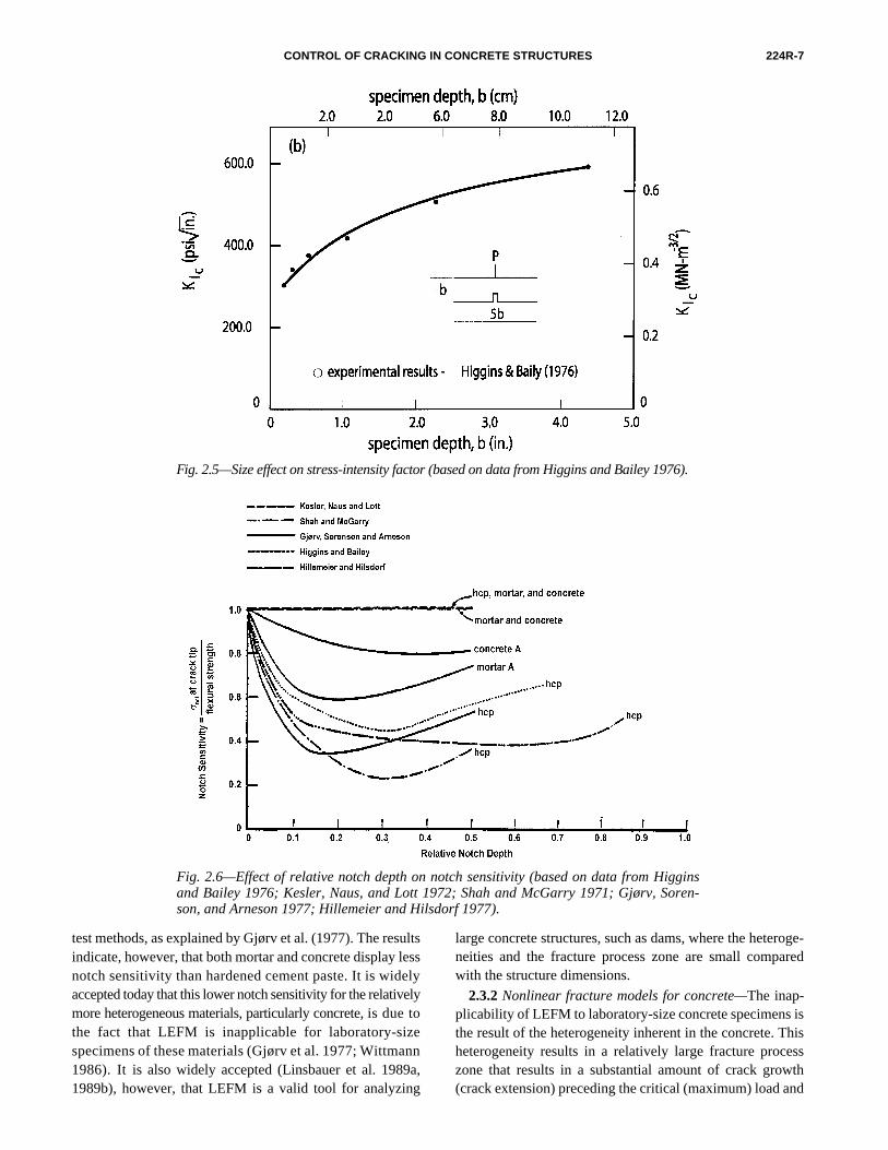
CONTROL OF CRACKING IN CONCRETE STRUCTURES 224R-7
Fig. 2.5—Size effect on stress-intensity factor (based on data from Higgins and Bailey 1976).
Fig. 2.6—Effect of relative notch depth on notch sensitivity (based on data from Higginsand Bailey 1976; Kesler, Naus, and Lott 1972; Shah and McGarry 1971; Gjørv, Soren-son, and Arneson 1977; Hillemeier and Hilsdorf 1977).
test methods, as explained by Gjørv et al. (1977). The resultsindicate, however, that both mortar and concrete display lessnotch sensitivity than hardened cement paste. It is widelyaccepted today that this lower notch sensitivity for the relativelymore heterogeneous materials, particularly concrete, is due tothe fact that LEFM is inapplicable for laboratory-sizespecimens of these materials (Gjørv et al. 1977; Wittmann1986). It is also widely accepted (Linsbauer et al. 1989a,1989b), however, that LEFM is a valid tool for analyzing
large concrete structures, such as dams, where the heteroge-neities and the fracture process zone are small comparedwith the structure dimensions.
2.3.2 Nonlinear fracture models for concrete—The inap-plicability of LEFM to laboratory-size concrete specimens isthe result of the heterogeneity inherent in the concrete. Thisheterogeneity results in a relatively large fracture processzone that results in a substantial amount of crack growth(crack extension) preceding the critical (maximum) load and

224R-8 ACI COMMITTEE REPORT
Fig. 2.7—Precritical crack growth (John and Shah 1986).
Fig. 2.8—Normalized peak stress versus crack width in unaxial tension (Gopalratnam andShah 1986).
is responsible for the strong dependence of KIc on the sizeand geometry of test specimens. Precritical crack growth(crack extension) for a notched beam test is shown in Fig. 2.7,where the crack growth ahead of the notch was continuouslymonitored using a specially developed brittle crack gage (Johnand Shah 1986).
The fracture process zone in concrete is substantially dif-ferent from the plastic zone in metals. For metals, the plasticzone is defined as a zone where the material has yieldedahead of the crack. LEFM is based on the assumption that theplastic zone is substantially smaller than the dimensions of
the test specimen. Laboratory-size specimens satisfy this cri-terion for metals. For concrete, Bažant (1979) stated that thefracture process zone has a negligible effect if the cross-sectional dimensions of a member is at least 100 times themaximum aggregate size, which would lead to prohibitivesize requirements. For instance, concrete with 19 mm (3/4 in.)aggregates would require a beam with a depth of at least of 2 m(6 ft). In view of these specimen size requirements, whenLEFM is not applicable for many of the fracture tests thathave been conducted on concrete. Therefore, if laboratory-sizespecimens are used to evaluate the fracture toughness of
CONTROL OF CRACKING IN CONCRETE STRUCTURES 224R-9
concrete, it is imperative that the effect of the process zoneis considered.
Figure 2.8 shows the results of a uniaxial tensile testconducted by Gopalaratnam and Shah (1986). The average(surface) crack opening displacements during this testwere measured microscopically. The peak of the curve,shown in Fig. 2.8 at zero displacement, is assumed to beequal to the tensile strength of the concrete, and the area un-der the curve is considered to be the fracture energy of theconcrete Gf .
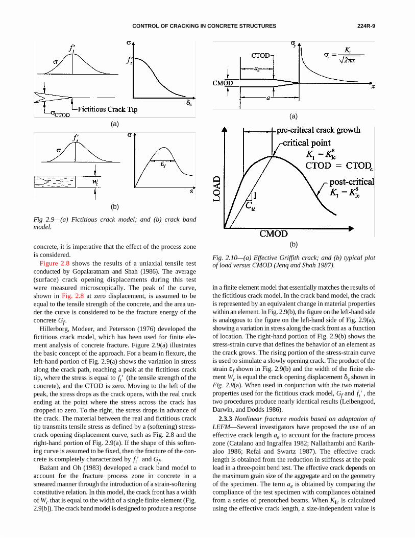
Hillerborg, Modeer, and Petersson (1976) developed thefictitious crack model, which has been used for finite ele-ment analysis of concrete fracture. Figure 2.9(a) illustratesthe basic concept of the approach. For a beam in flexure, theleft-hand portion of Fig. 2.9(a) shows the variation in stressalong the crack path, reaching a peak at the fictitious cracktip, where the stress is equal to (the tensile strength of theconcrete), and the CTOD is zero. Moving to the left of thepeak, the stress drops as the crack opens, with the real crackending at the point where the stress across the crack hasdropped to zero. To the right, the stress drops in advance ofthe crack. The material between the real and fictitious cracktip transmits tensile stress as defined by a (softening) stress-crack opening displacement curve, such as Fig. 2.8 and theright-hand portion of Fig. 2.9(a). If the shape of this soften-ing curve is assumed to be fixed, then the fracture of the con-crete is completely characterized by and Gf.
Bažant and Oh (1983) developed a crack band model toaccount for the fracture process zone in concrete in asmeared manner through the introduction of a strain-softeningconstitutive relation. In this model, the crack front has a widthof Wc that is equal to the width of a single finite element (Fig.2.9[b]). The crack band model is designed to produce a response
ft ′
ft ′
(a)
Fig 2.9—(a) Fictitious crack model; and (b) crack bandmodel.
(b)
in a finite element model that essentially matches the results ofthe fictitious crack model. In the crack band model, the crackis represented by an equivalent change in material propertieswithin an element. In Fig. 2.9(b), the figure on the left-hand sideis analogous to the figure on the left-hand side of Fig. 2.9(a),showing a variation in stress along the crack front as a functionof location. The right-hand portion of Fig. 2.9(b) shows thestress-strain curve that defines the behavior of an element asthe crack grows. The rising portion of the stress-strain curveis used to simulate a slowly opening crack. The product of thestrain εf shown in Fig. 2.9(b) and the width of the finite ele-ment Wc is equal the crack opening displacement δc shown inFig. 2.9(a). When used in conjunction with the two materialproperties used for the fictitious crack model, Gf and , thetwo procedures produce nearly identical results (Leibengood,Darwin, and Dodds 1986).
2.3.3 Nonlinear fracture models based on adaptation ofLEFM—Several investigators have proposed the use of aneffective crack length ae to account for the fracture processzone (Catalano and Ingraffea 1982; Nallathambi and Karih-aloo 1986; Refai and Swartz 1987). The effective cracklength is obtained from the reduction in stiffness at the peakload in a three-point bend test. The effective crack depends onthe maximum grain size of the aggregate and on the geometryof the specimen. The term ae is obtained by comparing thecompliance of the test specimen with compliances obtainedfrom a series of prenotched beams. When KIc is calculatedusing the effective crack length, a size-independent value is
ft ′
Fig. 2.10—(a) Effective Griffith crack; and (b) typical plotof load versus CMOD (Jenq and Shah 1987).
(a)
(b)

224R-10 ACI COMMITTEE REPORT
obtained. Refai and Swartz (1987) developed empiricalequations that relate effective crack length with specimengeometry and material properties.
Jenq and Shah (1987) proposed a method to determine theeffective crack length, which is then used to calculate a crit-ical stress-intensity factor Ks
Ic and a critical crack tip openingdisplacement (CTOD). Figure 2.10 illustrates the effectivecrack-length concept. The effective crack length concept it-self is the sum of a measurable crack, visible on the side of aspecimen, plus the additional crack length represented by thefracture process zone. The effective crack length is evaluatedusing the unloading compliance measurement Cu of theload-CMOD curve at the point of maximum load, as shownin Fig. 2.10(b). Jeng and Shah found that the effective cracklength calculated from compliance measurements is thesame as that obtained using LEFM and assuming that CTODhas a critical value, which was found to be independent of thesize and geometry of the beams tested and may be consideredto be a valid fracture parameter.
2.3.4 Size effect of fracture—The effect of structural sizeon the fracture of concrete is perhaps the most compellingreason for using fracture mechanics (ACI 446.1R).
For blunt fracture (as occurs in a crack with a diffuse fractureprocess zone in materials such as concrete), the total potential-energy release caused by fracture in a given structure dependson the length of the fracture and the area traversed by the frac-ture process zone so that the size of the fracture process zone isconstant and independent of the size of the structure. Dimen-sional analysis then shows that the structural size effectfor geometrically similar specimens or structures is governedby the simple relation (Bažant, Kim, and Pfeiffer 1986)
(2-1)
whereσΝ = P/bd = nominal stress at failure;
σNBft′
1 d d⁄ o+( )------------------------------=
Fig. 2.11—Size-effect law (Bažant, Kim, and Pfeiffer 1986).
P = maximum load (that is, failure load);b = thickness;d = characteristic dimension of the specimen or structure;
= direct tensile strength; andB, do = empirical constants, do being a certain multiple of the
maximum size of inhomogeneities in the material da.The value of B and the ratio of do /da depends only on theshape of the structure, not on its size. Figure 2.11 showsthe relationship between nominal stress at failure and size.
If the structure is very small, the second term in parenthe-ses, d /do of Eq. (2-1), is negligible compared with 1, andσΝ = Β is the failure condition that represents the strengthcriterion and corresponds to the horizontal line in Fig. 2.11.If the structure is very large, 1 is negligible compared with d/doand σΝ = constant / . This is the typical size effect in LEFM;it corresponds to the inclined straight line in Fig. 2.11.According to Eq. (2-1), the size effect in blunt fracturerepresents a gradual transition from the strength criterion tothe energy criterion of LEFM.
The size-effect law has been used by Bažant and Sun(1987); Bažant and Sener (1988); and Bažant, Sener, andPratt (1988) to predict the size effects for shear, torsion, andbond pullout testing of concrete.
2.3.5 Effect of material properties on fracture—Certainmaterial properties, especially w/cm, play an important rolein controlling the compressive strength and durability ofconcrete. The effect of these material properties on thefracture of concrete are not certain; however, some studieshave specifically addressed this question. Early work byNaus and Lott (1969) indicated that the fracture toughness ofcement paste and mortar increases with decreasing w/cm, butw/cm has little effect on the fracture toughness of concrete.Naus and Lott found that KIc increases with age and decreaseswith increasing air content for paste, mortar, and concrete. Thefracture toughness of mortar increases with increasing sandcontent, and the fracture toughness of concrete increaseswith an increase in the maximum size of the coarse aggre-gate. Gettu, Bažant, and Karr (1990), in a study of the frac-ture properties of high-strength concrete, made a number ofobservations that match those obtained in the earlier work.They observed that the fracture toughness and fracture energyobtained with high-strength concrete is not much higher thanthat for lower-strength concrete, and any increase that occursis at a rate less than in proportion to the square root ofcompressive strength. The work by Gettu, Bažant, andKarr (1990) was carried out with mixtures that maintaineda constant maximum-size aggregate. When the results oftheir work are combined with the typical procedure of usingsmaller maximum-size aggregate for high-strength concrete,it becomes clear that improvements in compressive strength,obtained with the use of increased cement contents, mineraladmixtures, high-range water-reducers, and with the ac-companying reduction in total aggregate volume, will notincrease fracture toughness. The result is that structuralmembers made with high-strength concrete will exhibit alower-than-expected capacity when the member strengthdepends on the concrete tensile strength, and the design isbased on . Specific examples are flexural cracking,
ft ′
ft ′
d
fc′
CONTROL OF CRACKING IN CONCRETE STRUCTURES 224R-11
CHAPTER 3—CONTROL OF CRACKING DUE TO DRYING SHRINKAGE
3.1—IntroductionDrying shrinkage of concrete is the reduction in volume
caused by the loss of water. Drying shrinkage can be definedas the time-dependent linear strain at constant temperaturemeasured on an unloaded specimen that is allowed to dry.From a structural point of view, there is no need to separatedrying shrinkage from other kinds of phenomena, such ascarbonation shrinkage and autogenous shrinkage. A typicalvalue for the final shrinkage strain of concrete in structuresis 600 × 10-6. Because the concrete tensile-strain capacitycan be 150 × 10-6 or less, cracking will result if the shrinkageis restrained in a concrete member. There is a high degree ofuncertainty in predicting shrinkage of concrete structures,however, because this property varies considerably withmany parameters, including concrete composition, source ofaggregate, ambient relative humidity, specimen geometry,and more specifically, the ratio of the exposed surface to thevolume of the structural element. Further, the slow developmentof shrinkage over time makes it difficult to obtain an accurateprediction for a given concrete from short-term laboratorymeasurements. As a result, a coefficient variation of 20% ormore can be expected in predicting long-term shrinkage.
Before true moisture equilibrium has been reached withina member cross section, internal shrinkage restraint occursbecause of moisture gradients. Consequently, self-equilibratinginternal stresses are present with tension on the surface andcompression in the interior. This stress condition can causecracking if not relieved by creep.
Shrinkage and creep are often responsible for excessivedeflections and curvature, losses in prestress, and redistribu-tion of internal stresses and reactions in statically indetermi-nate members. If not controlled, drying shrinkage can lead toserviceability problems, such as excessive deflections, anddurability problems, such as freeze-thaw deterioration andcorrosion at cracks.
Good design and construction practices can minimizethe amount of cracking and eliminate or control the visiblelarge cracks by minimizing the restraint using adequatereinforcement and contraction joints. Further informationcan be found in ACI 209R. Cracking due to drying shrinkagecan never be eliminated in most structures. This chapter cov-ers cracking of hardened concrete due to drying shrinkage,factors influencing shrinkage, control of cracking, and theuse of expansive cements to minimize cracking. Construc-tion practices and specifications to minimize drying shrink-age are covered in Chapter 8.
shear strength, and bond strength between concrete andreinforcing steel. The impact of using high-strength concrete onthese load-carrying mechanisms needs additional study.
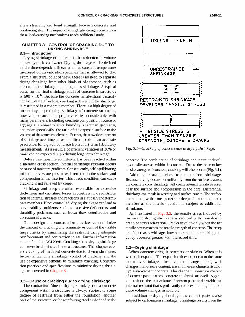
3.2—Cause of cracking due to drying shrinkageThe contraction (due to drying shrinkage) of a concrete
component within a structure is always subject to somedegree of restraint from either the foundation, anotherpart of the structure, or the reinforcing steel embedded in the
concrete. The combination of shrinkage and restraint devel-ops tensile stresses within the concrete. Due to the inherent lowtensile strength of concrete, cracking will often occur (Fig. 3.1).
Additional restraint arises from nonuniform shrinkage.Because drying occurs nonuniformly from the surface towardsthe concrete core, shrinkage will create internal tensile stressesnear the surface and compression in the core. Differentialshrinkage can result in warping and surface cracks. The surfacecracks can, with time, penetrate deeper into the concretemember as the interior portion is subject to additionalshrinkage.
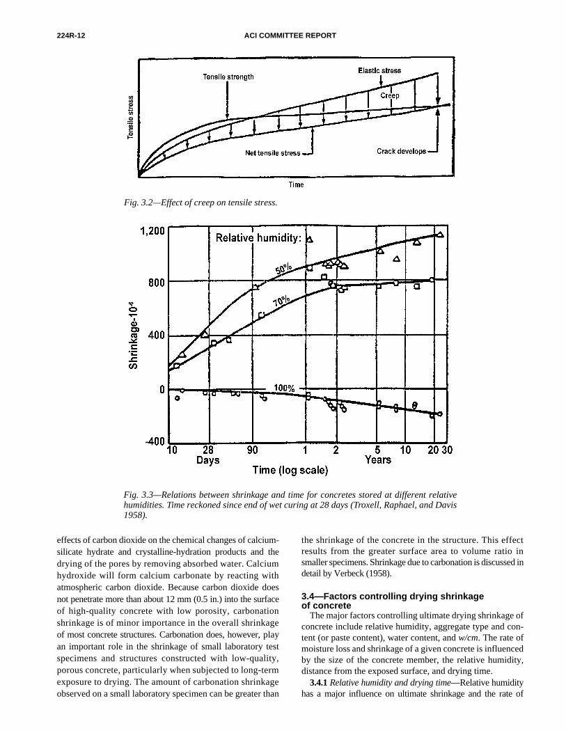
As illustrated in Fig. 3.2, the tensile stress induced by
Fig. 3.1—Cracking of concrete due to drying shrinkage.
restraining drying shrinkage is reduced with time due tocreep or stress relaxation. Cracks develop only when the nettensile stress reaches the tensile strength of concrete. The creeprelief decreases with age, however, so that the cracking ten-dency becomes greater with increased time.
3.3—Drying shrinkageWhen concrete dries, it contracts or shrinks. When it is
wetted, it expands. The expansion does not occur to the sameextent as shrinkage. These volume changes, along withchanges in moisture content, are an inherent characteristic ofhydraulic-cement concrete. The change in moisture contentof cement paste causes concrete to shrink or swell. Aggre-gate reduces the unit volume of cement paste and provides aninternal restraint that significantly reduces the magnitude ofthese volume changes in concrete.
In addition to drying shrinkage, the cement paste is alsosubject to carbonation shrinkage. Shrinkage results from the
224R-12 ACI COMMITTEE REPORT
Fig. 3.2—Effect of creep on tensile stress.
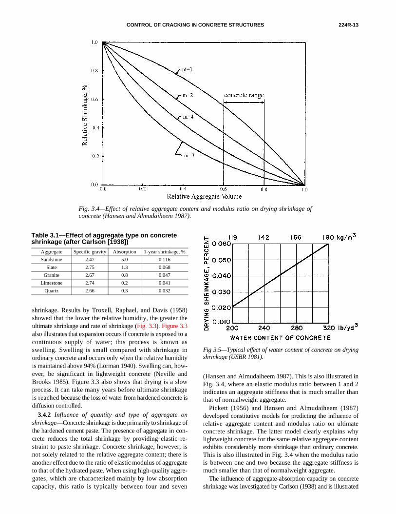
Fig. 3.3—Relations between shrinkage and time for concretes stored at different relativehumidities. Time reckoned since end of wet curing at 28 days (Troxell, Raphael, and Davis1958).
effects of carbon dioxide on the chemical changes of calcium-silicate hydrate and crystalline-hydration products and thedrying of the pores by removing absorbed water. Calciumhydroxide will form calcium carbonate by reacting withatmospheric carbon dioxide. Because carbon dioxide doesnot penetrate more than about 12 mm (0.5 in.) into the surfaceof high-quality concrete with low porosity, carbonationshrinkage is of minor importance in the overall shrinkageof most concrete structures. Carbonation does, however, playan important role in the shrinkage of small laboratory testspecimens and structures constructed with low-quality,porous concrete, particularly when subjected to long-termexposure to drying. The amount of carbonation shrinkageobserved on a small laboratory specimen can be greater than
the shrinkage of the concrete in the structure. This effectresults from the greater surface area to volume ratio insmaller specimens. Shrinkage due to carbonation is discussed indetail by Verbeck (1958).
3.4—Factors controlling drying shrinkage of concrete
The major factors controlling ultimate drying shrinkage ofconcrete include relative humidity, aggregate type and con-tent (or paste content), water content, and w/cm. The rate ofmoisture loss and shrinkage of a given concrete is influencedby the size of the concrete member, the relative humidity,distance from the exposed surface, and drying time.
3.4.1 Relative humidity and drying time—Relative humidityhas a major influence on ultimate shrinkage and the rate of
CONTROL OF CRACKING IN CONCRETE STRUCTURES 224R-13
Fig. 3.4—Effect of relative aggregate content and modulus ratio on drying shrinkage ofconcrete (Hansen and Almudaiheem 1987).
shrinkage. Results by Troxell, Raphael, and Davis (1958)showed that the lower the relative humidity, the greater theultimate shrinkage and rate of shrinkage (Fig. 3.3). Figure 3.3also illustrates that expansion occurs if concrete is exposed to acontinuous supply of water; this process is known asswelling. Swelling is small compared with shrinkage inordinary concrete and occurs only when the relative humidityis maintained above 94% (Lorman 1940). Swelling can, how-ever, be significant in lightweight concrete (Neville andBrooks 1985). Figure 3.3 also shows that drying is a slowprocess. It can take many years before ultimate shrinkageis reached because the loss of water from hardened concrete isdiffusion controlled.
3.4.2 Influence of quantity and type of aggregate onshrinkage—Concrete shrinkage is due primarily to shrinkage ofthe hardened cement paste. The presence of aggregate in con-crete reduces the total shrinkage by providing elastic re-straint to paste shrinkage. Concrete shrinkage, however, isnot solely related to the relative aggregate content; there isanother effect due to the ratio of elastic modulus of aggregateto that of the hydrated paste. When using high-quality aggre-gates, which are characterized mainly by low absorptioncapacity, this ratio is typically between four and seven
Table 3.1—Effect of aggregate type on concrete shrinkage (after Carlson [1938])
Aggregate Specific gravity Absorption 1-year shrinkage, %
Sandstone 2.47 5.0 0.116
Slate 2.75 1.3 0.068
Granite 2.67 0.8 0.047
Limestone 2.74 0.2 0.041
Quartz 2.66 0.3 0.032
(Hansen and Almudaiheem 1987). This is also illustrated inFig. 3.4, where an elastic modulus ratio between 1 and 2indicates an aggregate stiffness that is much smaller thanthat of normalweight aggregate.
Pickett (1956) and Hansen and Almudaiheem (1987)developed constitutive models for predicting the influence ofrelative aggregate content and modulus ratio on ultimateconcrete shrinkage. The latter model clearly explains whylightweight concrete for the same relative aggregate contentexhibits considerably more shrinkage than ordinary concrete.This is also illustrated in Fig. 3.4 when the modulus ratiois between one and two because the aggregate stiffness ismuch smaller than that of normalweight aggregate.
The influence of aggregate-absorption capacity on concreteshrinkage was investigated by Carlson (1938) and is illustrated
Fig 3.5—Typical effect of water content of concrete on dryingshrinkage (USBR 1981).

224R-14 ACI COMMITTEE REPORT
in Table 3.1; the concrete had identical cements and w/cms. Theabsorption of an aggregate, which is a measure of porosity, in-fluences its modulus or compressibility. A low elastic modu-lus is usually associated with high absorption.
Quartz, limestone, dolomite, granite, feldspar, and somebasalts can be classified as higher-modulus aggregates,which result in lower shrinkage properties of concrete. High-shrinkage concrete often contains sandstone, slate, horn-blende, and some types of basalts. Because the rigidity ofcertain aggregates, such as granite, limestone, or dolomite,can vary over a wide range, their effectiveness in restrainingdrying shrinkage varies.
Although compressibility is the most important propertyof aggregate governing concrete shrinkage, the aggregateitself can shrink during drying. This is true for sandstoneand other aggregates of high-absorption capacity. In general,aggregate with a high modulus of elasticity and low absorptionwill produce a concrete with low ultimate shrinkage.
Fig. 3.6—Effect of temperature of fresh concrete on itswater requirement (USBR 1981).
Fig. 3.7—Influence of w/c and aggregate content on shrinkage(Odman 1968).
3.4.3 Paste content and w/cm—Consistency, as measuredby the slump test, is an important parameter in proportioningconcrete. The amount of mixing water needed to achieve agiven slump is dependent on the maximum aggregate sizeused because the maximum size influences the total aggregatesurface area that needs to be covered with cement paste.Decreasing maximum aggregate size increases the totalsurface area to be covered with paste. Therefore, more waterand cement are needed to achieve a given slump. For thesame w/cm, concrete shrinkage increases with increasingwater content because the paste volume increases; thisagrees with the predictions in Fig. 3.4 and results obtained bythe U.S. Bureau of Reclamation (1975) shown in Fig. 3.5.For a constant w/cm, there is an approximately linear rela-tionship between water content (paste content as well) andconcrete shrinkage within the range of water contents listed.Temperature also has an influence on the water requirementsof the fresh concrete for same slump (Fig. 3.6). A reductionin water content, which reduces the paste content, will re-duce the ultimate drying shrinkage of concrete. Therefore,the water content (and paste content) of a concrete mix-ture should be kept to a minimum to minimize potential dry-ing shrinkage and the cracking tendency of the concrete.
Figure 3.7 illustrates that concrete shrinkage increaseswith w/cm for a given aggregate content. This effect is morepronounced with lower aggregate contents (Odman 1968).
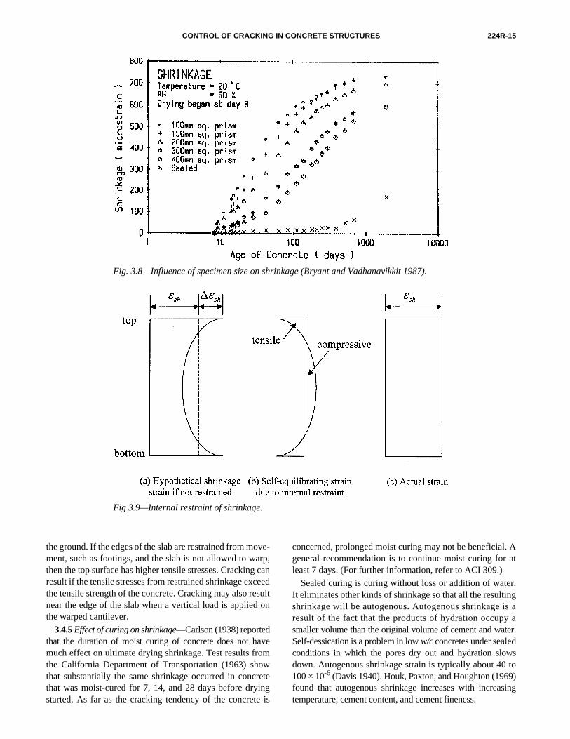
3.4.4 Influence of member size—The size and shape of aconcrete member and the porosity of the cement paste influ-ences the drying rate of concrete and, therefore, influencesthe shrinkage rate. The shape affects the ratio of the surfacearea to volume of the member, and a higher ratio results in ahigher drying rate. For a given concrete, the observed shrinkageat a given time decreases with an increase in the size of thespecimen. This effect is illustrated in Fig. 3.8 (Bryant and
Vadhanavikkit 1987) in which long-term shrinkage resultswere obtained on concrete prisms up to 400 mm (8 in.) thick.Ultimate shrinkage may not be reached for structural membersduring the intended service life.Another consequence of moisture diffusion is that a mois-ture gradient develops from the surface to the interior. For aspecimen that has moisture evaporation from all surfaces,shrinkage strain is greatest at the surface where moisturecontent is lowest, and shrinkage strain decreases toward thecenter where moisture content is highest. Nonuniform self-equilibrating internal stresses develop. Tensile stresses occurat and near the surfaces and compressive stresses develop atand near core, as shown in Fig. 3.9.
Warping occurs if drying takes place in an unsymmetricalmanner, either due to drying from one side or due to a non-symmetrical structure. In slabs-on-grade, the warping mech-anism is a primary cause of cracking. Moisture evaporatesfrom the top surface only, which causes higher shrinkage atthe top. The concrete near the top surface is partially re-strained from shrinking because it is attached to concretelower in the slab that is more moist and does not shrink asmuch as the top surface. This restraint produces tensilestresses at and near the top surface, which results in the slabwarping or curling, and the free edges of the slab can lift off
CONTROL OF CRACKING IN CONCRETE STRUCTURES 224R-15
Fig. 3.8—Influence of specimen size on shrinkage (Bryant and Vadhanavikkit 1987).
Fig 3.9—Internal restraint of shrinkage.
the ground. If the edges of the slab are restrained from move-ment, such as footings, and the slab is not allowed to warp,then the top surface has higher tensile stresses. Cracking canresult if the tensile stresses from restrained shrinkage exceedthe tensile strength of the concrete. Cracking may also resultnear the edge of the slab when a vertical load is applied onthe warped cantilever.
3.4.5 Effect of curing on shrinkage—Carlson (1938) reportedthat the duration of moist curing of concrete does not havemuch effect on ultimate drying shrinkage. Test results fromthe California Department of Transportation (1963) showthat substantially the same shrinkage occurred in concretethat was moist-cured for 7, 14, and 28 days before dryingstarted. As far as the cracking tendency of the concrete is
concerned, prolonged moist curing may not be beneficial. Ageneral recommendation is to continue moist curing for atleast 7 days. (For further information, refer to ACI 309.)
Sealed curing is curing without loss or addition of water.It eliminates other kinds of shrinkage so that all the resultingshrinkage will be autogenous. Autogenous shrinkage is aresult of the fact that the products of hydration occupy asmaller volume than the original volume of cement and water.Self-dessication is a problem in low w/c concretes under sealedconditions in which the pores dry out and hydration slowsdown. Autogenous shrinkage strain is typically about 40 to100 × 10-6 (Davis 1940). Houk, Paxton, and Houghton (1969)found that autogenous shrinkage increases with increasingtemperature, cement content, and cement fineness.
224R-16 ACI COMMITTEE REPORT
3.4.6 Effect of admixtures—The effect of admixtures onconcrete shrinkage is unclear. As an example, early-ageshrinkage appears to increase by about 100% in the presenceof calcium chloride, whereas later-age shrinkage is increasedby about 40% compared with control specimens (ACI 212.3R).
Air-entrainment does not seem to increase shrinkage bymore than 10% for air contents up to about 5% (Carlson 1938).
Results by Ghosh and Malhotra (1979), Brooks, Wain-wright, and Neville (1979), and Feldman and Swenson(1975) indicated that the use of high-range water-reducingadmixtures increases shrinkage. According to Ytterberg (1987),high-range water-reducing admixtures do not necessarilyreduce shrinkage in proportion to their ability to reducewater content.
3.5—Control of shrinkage crackingConcrete tends to shrink due to drying whenever its sur-
faces are exposed to air of low relative humidity or highwinds. Because various kinds of restraint prevent the con-crete from contracting freely, cracking should be expected,unless the ambient relative humidity is kept near 100%. The con-trol of cracking consists of reducing the cracking tendency to aminimum, using adequate and properly positioned reinforce-ment, and using contraction joints. The CEB-FIP ModelCode (1990) gives quantitative recommendations on thecontrol of cracking due to shrinkage by listing various coef-ficients to determine the shrinkage levels that can be expected.Control of cracking by correct construction practices iscovered in Chapter 8.
Cracking can also be minimized by using expansive cementsto produce shrinkage-compensating concrete. This is discussedin Section 3.6.
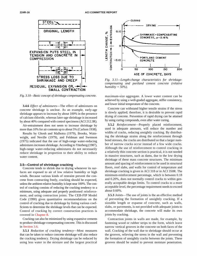
Fig. 3.10—Basic concept of shrinkage-compensating concrete.
3.5.1 Reduction of cracking tendency—Most measuresthat can be taken to reduce concrete shrinkage will also reducethe cracking tendency. Drying shrinkage can be reduced byusing less water in the mixture and the largest practical
maximum-size aggregate. A lower water content can beachieved by using a well-graded aggregate, stiffer consistency,and lower initial temperature of the concrete.
Concrete can withstand higher tensile strains if the stressis slowly applied; therefore, it is desirable to prevent rapiddrying of concrete. Prevention of rapid drying can be attainedby using curing compounds, even after water curing.
3.5.2 Reinforcement—Properly placed reinforcement,used in adequate amounts, will reduce the number andwidths of cracks, reducing unsightly cracking. By distribut-ing the shrinkage strains along the reinforcement throughbond stresses, the cracks are distributed so that a larger num-ber of narrow cracks occur instead of a few wide cracks.Although the use of reinforcement to control cracking ina relatively thin concrete section is practical, it is not neededin massive structures, such as dams, due to the low dryingshrinkage of these mass concrete structures. The minimumamount and spacing of reinforcement to be used in structuralfloors, roof slabs, and walls for control of temperature andshrinkage cracking is given in ACI 318 or in ACI 350R. Theminimum-reinforcement percentage, which is between 0.18and 0.20%, does not normally control cracks to within gen-erally acceptable design limits. To control cracks to a moreacceptable level, the percentage requirement needs to exceedabout 0.60%.
3.5.3 Joints—The use of joints is the an effective methodof preventing the formation of unsightly cracking. If asizeable length or expanse of concrete, such as walls,slabs, or pavements, is not provided with adequate joints toaccommodate shrinkage, the concrete will make its ownjoints by cracking.
Contraction joints in walls are made, for example, byfastening wood or rubber strips to the form, which leavenarrow vertical grooves in the concrete on both faces of thewall. Cracking of the wall due to shrinkage should occur atthe grooves, relieving the stress in the wall and preventingthe formation of unsightly cracks between the joints. Thesegrooves should be sealed to prevent moisture penetration.
Fig. 3.11—Length-change characteristics for shrinkage-compensating and portland cement concrete (relativehumidity = 50%).
CONTROL OF CRACKING IN CONCRETE STRUCTURES 224R-17
CHAPTER 4—CONTROL OF CRACKING IN FLEXURAL MEMBERS
4.1—IntroductionThe control of cracking can be as important as the control
of deflection in flexural members. Cracking in the tension
3.6—Shrinkage-compensating concreteShrinkage-compensating concrete made with expansive
cements can be used to minimize or eliminate shrinkagecracking. The properties and use of expansive cement con-crete are summarized in ACI 223, ACI 223 (1970), ACI SP-38, and ACI SP-64. Of the several expansive cements pro-duced in the past, Type K shrinkage-compensating cement(ASTM C 845) is currently the only one available in theUnited States. Several component materials are available toproduce shrinkage-compensating concrete.
In reinforced shrinkage-compensating concrete, the expan-sion of the cement paste during the first few days of hydrationwill develop a low level of prestress, inducing tensile stresses inthe steel and compressive stresses in the concrete. The level ofcompressive stresses developed in the shrinkage-compensatingconcrete ranges from 0.2 to 0.7 MPa (25 to 100 psi). Normalshrinkage occurs when water starts to evaporate from theconcrete. The contraction of the concrete will result in areduction or elimination of its precompression. The initialexpansion of the concrete reduces the magnitude of anytensile stress that develops due to restrained shrinkage. Thisbasic concept of using expansive cement to produce ashrinkage-compensating concrete is illustrated in Fig. 3.10.To allow for adequate expansion, special details may beneeded at joints.
A typical length-change history of a shrinkage-compensatingconcrete is compared to that of a portland cement concrete inFig. 3.11. The amount of reinforcing steel normally used inreinforced concrete made with portland cements is usually morethan adequate to provide the elastic restraint needed forshrinkage-compensating concrete. To take full advantageof the expansive potential of shrinkage-compensating concretein minimizing or preventing shrinkage cracking of exposedconcrete surfaces, it is important that positive and uninterruptedwater curing (wet covering or ponding) be started immediatelyafter final finishing. For slabs on well-saturated subgrades,curing by sprayed-on membranes or moisture-proof covershas been successfully used. Inadequate curing of shrinkage-compensating concrete can result in an insufficient expansionto elongate the steel and subsequent cracking from dryingshrinkage. Specific recommendations and information onthe use of shrinkage-compensating concrete are containedin ACI 223R.
Sawed joints are commonly used in pavements and slabs-on-grade. Joint location depends on the particulars of place-ment. Each element should be studied individually to deter-mine where the joints should be placed. ACI 224.3Rdiscusses the use of joints in concrete construction. Guidanceon joint sealants and contraction joint location in slabs is avail-able in ACI 504R and ACI 302.1R.
zone of a reinforced beam starts at stress levels as low as20 MPa (3000 psi) in the reinforcement. Crack control isalso important to aesthetics of exposed concrete surfaces.
The role of cracks in the corrosion of reinforcing steel iscontroversial (ACI 222R). One viewpoint is that cracks re-duce the service life of structures by permitting more rapidpenetration of carbonation and allow chloride ions, moisture,and oxygen to reach the reinforcing steel. Another point ofview is that while cracks accelerate the onset of corrosion,the corrosion is localized. With time, chlorides and waterpenetrate uncracked concrete and initiate more widespreadcorrosion. Consequently, after a few years of service, thereis little difference between the amount of corrosion incracked and uncracked concrete. More important parametersfor corrosion protection are concrete cover and concrete quality.
This chapter is concerned primarily with cracks caused byflexural and tensile stresses, but temperature, shrinkage,shear, and torsion can also lead to cracking. Cracking in certainspecialized structures, such as reinforced concrete tanks, bins,silos, and environmental structures is not covered in this re-port. Cracking of concrete in these structures is described byYerlici (1975), and in ACI 313 and ACI 350R.
Extensive research studies on the cracking behavior ofbeams have been conducted over the last 50 years. Most ofthe work conducted before 1970 was reviewed by ACICommittee 224 (1971) in ACI Bibliography No. 9. Additionalwork is referenced in this chapter. Leonhardt (1977 and 1988)presents an extensive review of cracking in reinforced- andprestressed-concrete structures. The CEB-FIP Model Code forConcrete Structures (1990) gives the European approach tocrack width evaluation and permissible crack widths.
The basis for codes of practice, both in the U.S. and Europe,to limit service-load cracking is rooted in equations to predictcrack widths. Several of the most important crack-predictionequations are reviewed in this report. The trend in reinforced-and prestressed concrete design to ensure acceptable crackingat service loads is to provide proper detailing, such as provi-sion of minimum reinforcement and proper selection of bardiameters, bar spacing, and reduction of restraint rather thantrying to make use of a sophisticated crack calculation(Schlaich, Schafer, and Jennewien 1987; Halvorsen 1987).
Fiber-reinforced polymer (FRP) bars have been used as areinforcing material (Nawy and Neuwerth 1977, Dolan1990). Experience is limited, however, and crack control instructures reinforced with these materials is not addressed inthis report.
4.2—Crack-control equations for reinforced concrete beams
A number of equations have been proposed for predictingcrack widths in flexural members; most of them were re-viewed in the original version of this committee report (ACICommittee 224 1972) and in key publications listed in thereferences. Crack control is provided by calculating theprobable crack width and proportioning structural elementsso that the computed width is less than some predefined value.Most equations predict the probable maximum crack width,which usually means that about 90% of the crack widths in

224R-18 ACI COMMITTEE REPORT
the member are below the calculated value. Research, how-ever, has shown that isolated cracks in beams in excess oftwice the computed maximum can occur (Holmberg andLindgren 1970) although generally, the coefficient of varia-tion of crack width is about 40% (Leonhardt 1977). There isevidence that this range in crack width variability can increasewith the size of the member (ACI Committee 224 1972).
Crack-control equations are presented in the sections thatfollow.
4.2.1 ACI approach through ACI 318-95—Requirementsfor flexural crack control in beams and thick one-way slabs(span-depth ratio in the range of 15 to 20) are based on thestatistical analysis (Gergely and Lutz 1968) of maximumcrack-width data from a number of sources. Based on theanalysis, the following general conclusions were reached:• The reinforcing steel stress is the most important variable;• The thickness of the concrete cover is an important
variable but not the only geometric consideration;• The area of concrete surrounding each reinforcing bar
is also an important geometric variable;• The bar diameter is not a major variable; and• The ratio of crack width at the surface to that at the
reinforcement level is proportional to the ratio of thenominal strain at the surface and the reinforcementstrain.
The equations that were considered to best predict theprobable maximum bottom and side crack widths are
(4-1a)
(4-1b)
wherewb = most probable maximum crack width at bottom of
beam, in.;ws = most probable maximum crack width at level of
reinforcement, in.;fs = reinforcing steel stress, ksi;A = area of concrete symmetric with reinforcing steel
divided by number of bars, in.2;tb = bottom cover to center of bar, in.;ts = side cover to center of bar, in.;β = ratio of distance between neutral axis and tension
face to distance between neutral axis and reinforc-ing steel about 1.20 in beams; and
h1 = distance from neutral axis to the reinforcing steel,in.
Simplification of Eq. (4-1a) yielded the following equation
(4-2a)
wherew = most probable maximum crack width, in.; and
wb 0.091 tbA3 β fs 5–( ) 10× 3–=
ws
0.091 tbA3
1 ts h1⁄+-------------------------- fs 5–( ) 10 3–×=
w 0.076βfs dcA3 10×3–
=
dc = thickness of cover from the extreme tension fiber tothe closest bar, in.
When the strain εs in the steel reinforcement is used insteadof stress fs, Eq. (4-2) becomes
(4-2b)
Eq. (4-3) is valid in any system of units.The cracking behavior in thick one-way slabs (span-depth
ratio 15 to 20) is similar to that in shallow beams. For one-way slabs with a clear concrete cover in excess of 25.4 mm(1 in.), Eq. (4-2) can be properly applied if β = 1.25 to 1.35is used.
ACI 318-95 Section 10.6 uses Eq. (4-2) with β = 1.2 in thefollowing form
(4-3)
and permits the calculation of z with fs equal to 60% of thespecified yield strength fy in lieu of exact calculation.
In ACI 318-95 and earlier code versions, the maximum al-lowable z = 175 kips per in. for interior exposure corre-sponds to a probable crack width of 0.41 mm (0.016 in.).This level of crack width may be excessive for aestheticconcerns.
ACI 318 has allowed a value of z = 145 kips per in. for ex-terior exposure based on a crack width value of 0.33 mm(0.013 in.). While application of Eq. (4-2a) ((Eq. 10-4) ofACI 318-95) to beams gives adequate crack-control values,its application to one-way slabs with standard 20 mm (3/4 in.)cover and reinforced with steel of 60 ksi (400 MPa) or loweryield strength results in large reinforcement spacings. Theprovisions of Section 7.6.5 of ACI 318-95, however, directlylimit the spacing of such reinforcement in one-way slabs.
ACI 340R contains design aids for the application ofEq. (4-3).
4.2.2 ACI 318-99 approach—ACI Committee 318 nowbelieves that it can be misleading to purport to effectivelycalculate crack widths, given the inherent variability incracking. The three important parameters in flexural crack-ing are steel stress, cover, and bar spacing. Steel stress is themost important parameter.
A reevaluation of cracking data (Frosch 1999) provided anew equation based on the physical phenomenon for thedetermination of the flexural crack widths of reinforcedconcrete members. This study showed that previous crackwidth equations are valid for a relatively narrow range ofcovers (up to 63 mm [2.5 in.]).
ACI 318-99, Section 10.6, does not make a distinctionbetween interior and exterior exposure. It requires that forcrack control in beams and one-way slabs, the spacing ofreinforcement closest to a surface in tension shall not exceedthat given by
(4-4a)
w 2.2βεs dcA3=
z fs dcA3=
s in.( ) 540 fs⁄( ) 2.5cc–[ ]=
CONTROL OF CRACKING IN CONCRETE STRUCTURES 224R-19
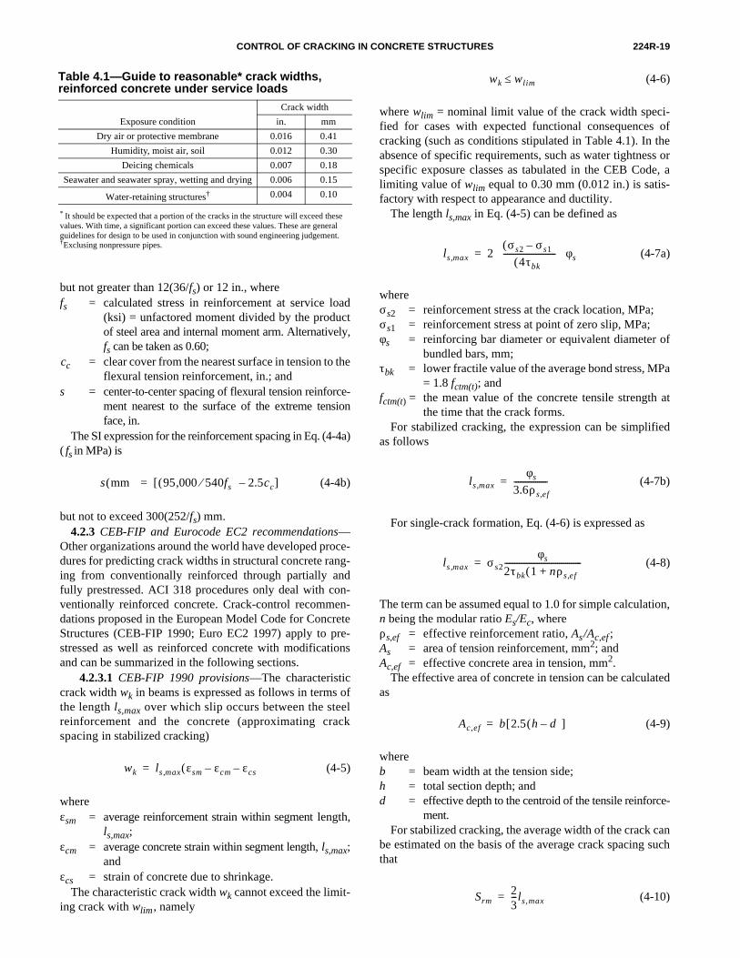
but not greater than 12(36/fs) or 12 in., wherefs = calculated stress in reinforcement at service load
(ksi) = unfactored moment divided by the productof steel area and internal moment arm. Alternatively,fs can be taken as 0.60;
cc = clear cover from the nearest surface in tension to theflexural tension reinforcement, in.; and
s = center-to-center spacing of flexural tension reinforce-ment nearest to the surface of the extreme tensionface, in.
The SI expression for the reinforcement spacing in Eq. (4-4a)( fs in MPa) is
(4-4b)
but not to exceed 300(252/fs) mm.4.2.3 CEB-FIP and Eurocode EC2 recommendations—
Other organizations around the world have developed proce-dures for predicting crack widths in structural concrete rang-ing from conventionally reinforced through partially andfully prestressed. ACI 318 procedures only deal with con-ventionally reinforced concrete. Crack-control recommen-dations proposed in the European Model Code for ConcreteStructures (CEB-FIP 1990; Euro EC2 1997) apply to pre-stressed as well as reinforced concrete with modificationsand can be summarized in the following sections.
4.2.3.1 CEB-FIP 1990 provisions—The characteristiccrack width wk in beams is expressed as follows in terms ofthe length ls,max over which slip occurs between the steelreinforcement and the concrete (approximating crackspacing in stabilized cracking)
(4-5)
whereεsm = average reinforcement strain within segment length,
ls,max;εcm = average concrete strain within segment length, ls,max;
andεcs = strain of concrete due to shrinkage.
The characteristic crack width wk cannot exceed the limit-ing crack with wlim, namely
yf
s mm( ) 95 000, 540fs⁄( ) 2.5cc–[ ]=
wk ls max, εsm εcm– εcs–( )=
* It should be expected that a portion of the cracks in the structure will exceed these values. With time, a significant portion can exceed these values. These are general guidelines for design to be used in conjunction with sound engineering judgement.†Exclusing nonpressure pipes.
Table 4.1—Guide to reasonable* crack widths, reinforced concrete under service loads
Exposure condition
Crack width
in. mm
Dry air or protective membrane 0.016 0.41
Humidity, moist air, soil 0.012 0.30
Deicing chemicals 0.007 0.18
Seawater and seawater spray, wetting and drying 0.006 0.15
Water-retaining structures† 0.004 0.10
(4-6)
where wlim = nominal limit value of the crack width speci-fied for cases with expected functional consequences ofcracking (such as conditions stipulated in Table 4.1). In theabsence of specific requirements, such as water tightness orspecific exposure classes as tabulated in the CEB Code, alimiting value of wlim equal to 0.30 mm (0.012 in.) is satis-factory with respect to appearance and ductility.
The length ls,max in Eq. (4-5) can be defined as
(4-7a)
whereσs2 = reinforcement stress at the crack location, MPa;σs1 = reinforcement stress at point of zero slip, MPa;φs = reinforcing bar diameter or equivalent diameter of
bundled bars, mm;τbk = lower fractile value of the average bond stress, MPa
= 1.8 fctm(t); andfctm(t) = the mean value of the concrete tensile strength at
the time that the crack forms.For stabilized cracking, the expression can be simplified
as follows
(4-7b)
For single-crack formation, Eq. (4-6) is expressed as
(4-8)
The term can be assumed equal to 1.0 for simple calculation,n being the modular ratio Es/Ec, whereρs,ef = effective reinforcement ratio, As/Ac,ef ;As = area of tension reinforcement, mm2; andAc,ef = effective concrete area in tension, mm2.
The effective area of concrete in tension can be calculatedas
(4-9)
whereb = beam width at the tension side;h = total section depth; andd = effective depth to the centroid of the tensile reinforce-
ment.For stabilized cracking, the average width of the crack can
be estimated on the basis of the average crack spacing suchthat
(4-10)
wk wlim≤
ls max, 2σs2 σs1–( )
4τbk( )-------------------------- φs⋅ ⋅=
ls max,φs
3.6ρs ef,
-----------------=
ls max, σs2φs
2τbk 1 nρs ef,+( )--------------------------------------=
Ac,ef b 2.5 h d–( )[ ]=
Srm23---ls ,max=
224R-20 ACI COMMITTEE REPORT
where Srm is the mean crack spacing value (mm) in the beam.4.2.3.2 Eurocode EC2 provisions—The Eurocode
EC2 requires that cracking should be limited to a levelthat does not impair the proper functioning of the structureor cause its appearance to be unacceptable (Euro EC2 1997;Beckett and Alexandrou 1997; Nawy 2001). It limits themaximum design crack width to 0.30 mm (0.012 in.) for sus-tained load under normal environmental conditions. Thisceiling is expected to be satisfactory with respect to ap-pearance and durability. Stricter requirements are stipulatedfor more severe environmental conditions.
The code stipulates that the design crack width be evaluatedfrom the following expression
(4-11)
wherewk = design crack width;srm = average stabilized crack spacing;εsm = mean strain under relevant combination of loads
and allowing for the effect such as tension stiffen-ing or shrinkage; and
β = coefficient relating the average crack width to thedesign value
= 1.7 for load-induced cracking and for restraintcracking in sections with minimum dimension inexcess of 800 mm (32 in.).
The strain εsm in the section is obtained from the followingexpression:
(4-12)
where
wk βsrmεsm=
εsm σs Es⁄ 1 β1β2 σsr σs⁄( )2–[ ]=
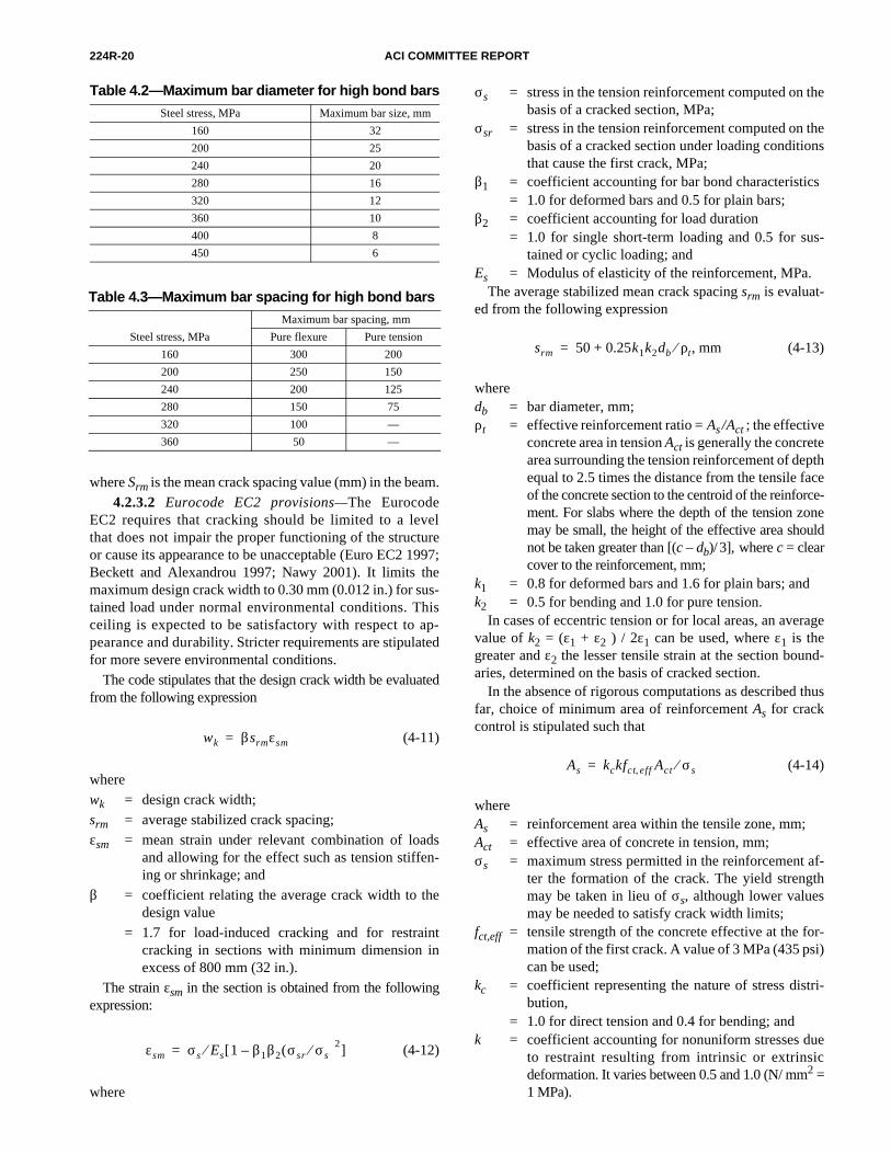
Table 4.2—Maximum bar diameter for high bond barsSteel stress, MPa Maximum bar size, mm
160 32
200 25
240 20
280 16
320 12
360 10
400 8
450 6
Table 4.3—Maximum bar spacing for high bond bars
Steel stress, MPa
Maximum bar spacing, mm
Pure flexure Pure tension
160 300 200
200 250 150
240 200 125
280 150 75
320 100 —
360 50 —
σs = stress in the tension reinforcement computed on thebasis of a cracked section, MPa;
σsr = stress in the tension reinforcement computed on thebasis of a cracked section under loading conditionsthat cause the first crack, MPa;
β1 = coefficient accounting for bar bond characteristics= 1.0 for deformed bars and 0.5 for plain bars;
β2 = coefficient accounting for load duration = 1.0 for single short-term loading and 0.5 for sus-
tained or cyclic loading; andEs = Modulus of elasticity of the reinforcement, MPa.
The average stabilized mean crack spacing srm is evaluat-ed from the following expression
(4-13)
wheredb = bar diameter, mm;ρt = effective reinforcement ratio = As / Act ; the effective
concrete area in tension Act is generally the concretearea surrounding the tension reinforcement of depthequal to 2.5 times the distance from the tensile faceof the concrete section to the centroid of the reinforce-ment. For slabs where the depth of the tension zonemay be small, the height of the effective area shouldnot be taken greater than [(c – db)/ 3], where c = clearcover to the reinforcement, mm;
k1 = 0.8 for deformed bars and 1.6 for plain bars; andk2 = 0.5 for bending and 1.0 for pure tension.
In cases of eccentric tension or for local areas, an averagevalue of k2 = (ε1 + ε2 ) / 2ε1 can be used, where ε1 is thegreater and ε2 the lesser tensile strain at the section bound-aries, determined on the basis of cracked section.
In the absence of rigorous computations as described thusfar, choice of minimum area of reinforcement As for crackcontrol is stipulated such that
(4-14)
whereAs = reinforcement area within the tensile zone, mm;Act = effective area of concrete in tension, mm;σs = maximum stress permitted in the reinforcement af-
ter the formation of the crack. The yield strengthmay be taken in lieu of σs, although lower valuesmay be needed to satisfy crack width limits;
fct,eff = tensile strength of the concrete effective at the for-mation of the first crack. A value of 3 MPa (435 psi)can be used;
kc = coefficient representing the nature of stress distri-bution,
= 1.0 for direct tension and 0.4 for bending; andk = coefficient accounting for nonuniform stresses due
to restraint resulting from intrinsic or extrinsicdeformation. It varies between 0.5 and 1.0 (N/ mm2 =1 MPa).
srm 50 0.25k1k2db ρt⁄ , mm+=
As kckfct eff, Act σs⁄=

CONTROL OF CRACKING IN CONCRETE STRUCTURES 224R-21
The EC2 Code also stipulates that for cracks dominantlycaused principally by flexure, their widths will not usual-ly exceed the standard 0.30 mm (0.012 in.) if the size andspacing of the reinforcing bars are within the range of valuesin Tables 4.2 and 4.3 for bar size and spacing (Euro EC21997; Beckett and Alexandrou 1997; Nawy 2001). For severeexposure conditions, such as those listed in Table 4.1, crackwidth computations become mandatory.
4.3—Crack control in two-way slabs and platesCrack-control equations for beams underestimate the
crack widths developed in two-way slabs and plates (Nawyand Blair 1971) and do not indicate to the designer how tospace the reinforcement. The cracking widths in two-wayslabs and plates are controlled primarily by the steel stresslevel and the spacing of the reinforcement in the two perpen-dicular directions. In addition, the clear concrete cover intwo-way slabs and plates is nearly constant (20 mm [3/4 in.]for most interior structural slabs), whereas it is a major vari-able in the crack-control equations for beams.
Analysis of data on cracking in two-way slabs and plates(Nawy and Blair 1971) has provided the following equationfor predicting the maximum crack width
(4-15)
where the terms inside the radical are collectively termed thegrid index:
k = fracture coefficient with a value k = 2.8 × 10⁻⁵ foruniformly loaded restrained two-way action squareslabs and plates. For concentrated loads or reactionsor when the ratio of short to long span is less than0.75 but larger than 0.5, a value of k = 2.1 × 10⁻⁵ isapplicable. For span aspect ratios less than 0.5, k =1.6 × 10⁻⁵;
β = 1.25 (chosen to simplify calculations, although itvaries between 1.20 and 1.35);
fs = actual average service-load stress level or 40% ofthe specified yield strength fy, ksi;
db1 = diameter of the reinforcement in Direction 1 closestto the concrete outer fibers, in.;
s1 = spacing of the reinforcement in Direction 1, in.;s2 = spacing of the reinforcement in perpendicular Di-
rection 2, in.;ρt1 = active steel ratio, that is, the area of steel As per ft
width/ [12db1 + 2c1], where c1 is clear concrete covermeasured from the tensile face of concrete to thenearest edge of the reinforcing bar in Direction 1;and
w = crack width at face of concrete caused by flexure, in.Direction 1 refers to the direction of reinforcement closest tothe outer concrete fibers; this is the direction for which
w kβfs I=
Idb1s2
ρt1
------------s1s2dc
db1
--------------- 8π---= =
crack-control check should be made. Subscripts 1 and 2 per-tain to the directions of reinforcement.
For simply supported slabs, the value of k should be mul-tiplied by 1.5. Interpolated k values apply for partial restraintat the boundaries. For zones of flat plates where transversesteel is not used or when its spacing s2 exceeds 305 mm (12 in.),use s2 = 305 mm (12 in.) in the equation.
If strain is used instead of stress, Eq. (4-15) becomes
(4-16)
where values of k1 = 29 × 103 times the k values previouslylisted. Nawy (1972) and ACI 340.1R contain design aids forapplying these recommendations.
Tam and Scanlon (1986) present a model for determiningdeflection of two-way slabs subjected to transverse loads.Their model accounts for the net effect on deflection of bothrestraint cracking and flexural cracking.
4.4—Tolerable crack widths versus exposure conditions in reinforced concrete
Table 4.1 presents a general guide for what could beconsidered reasonable crack widths at the tensile face ofreinforced concrete structures for typical conditions.These reasonable crack width values are intended to serveonly as a guide for proportioning reinforcement duringdesign. They are to be used as a general guideline alongwith sound engineering judgment.
The table is based primarily on Nawy (1968), who com-piled information from several sources. It is important tonote that these crack width values are not always a reliableindication of the corrosion and deterioration to be expected.In particular, a larger cover, even if it leads to a larger surfacecrack width, may be preferable for corrosion control in cer-tain environments; therefore, the designer should exerciseengineering judgment on the extent of crack control to beused. When used in conjunction with the recommendationspresented in Sections 4.2.1 and 4.2.3 to limit crack width, itshould be expected that a portion of the cracks in the struc-ture would exceed these values by a significant amount. It isalso noted that time effects, such as creep, will cause an in-crease in crack widths that should be taken into account bythe designer.
Another opinion regarding crack control suggests that inthe long term there is no link between the level of flexuralcracking and corrosion (Beeby 1983). This suggests that in-dependent of exposure conditions, the acceptable level ofcracking is primarily an aesthetic issue. Therefore, in casessuch as liquid-containing structures where the presence ofmoisture is constant or leakage is of concern should morerestrictive (smaller) crack widths be required. Based oninformation in Halvorsen (1987), a case could be made thatcrack widths ranging from 0.15 to 0.3 mm (0.006 to 0.012 in.)could be considered unacceptable for aesthetic reasons as theyare visible to the naked eye, hence generating a sense ofinsecurity or structural failure.
w k1βε I=
224R-22 ACI COMMITTEE REPORT
4.5—Flexural cracking in prestressed concretePartially prestressed members, in which cracks can appear
under working loads, are used extensively. Cracks form inthese members when the tensile stress exceeds the modulusof rupture of the concrete (6 to 9 psi under short-termconditions). The control of these cracks is necessary prima-rily for aesthetic reasons, as they are visible to the naked eye,hence generating a sense of structural insecurity. The resid-ual crack width, after removal of the major portion of the liveload, is small (about 0.03 to 0.09 mm [0.001 in. to 0.003 in.])and therefore, crack control is usually not necessary if thelive load is transient.
There have been studies concerning the calculation ofcrack widths in prestressed concrete members (Meier andGergely 1981; Suzuki and Yoshiteru 1984; Suri and Dilger1986; Nawy 1989a). The complexity of the crack width cal-culations is increased over reinforced concrete members bythe number of variables that should be considered.
4.5.1 Crack-prediction equations—One approach tocrack prediction for bonded prestressed beams has twosteps. First, the decompression moment is calculated, atwhich the stress in the concrete at the prestressing steel levelis zero. Then the member is treated as a reinforced concretemember and the increase in stress in the steel is calculatedfor the additional loading. The expressions given for crackprediction in nonprestressed beams can be used to estimatethe cracks for the load increase above the decompressionmoment. A multiplication factor of about 1.5 is neededwhen strands, rather than deformed bars, are used nearest tothe beam surface in the prestressed member to account forthe differences in bond properties. This approach is compli-cated if most of the parameters affecting cracking are con-sidered (Nilson 1987). An approximate method using thenominal-concrete-stress approach was presented by Meierand Gergely (1982). They proposed the following equationsfor prediction of maximum flexural crack width
(4-17)
(4-18)
whereC1, C2 = bond coefficients that depend on the type of steel
nearest the tension face;fct = nominal tensile stress at the tensile face;Ec = modulus of elasticity of concrete;dc = minimum concrete cover to centroid of steel at the
tensile face; andA = effective concrete area per bar as defined in ACI
318.Equation (4-17) is dimensionally correct and the coeffi-
cient C1 is dimensionless. In in.-lb units, C1 = 12 and C2 = 8.4for reinforcing bars, and C1 = 16 and C2 = 12 for strands. In SIunits, if A is specified in mm2, C1 = 1.39 and C2 = 0.97 forreinforcing bars, and C1 = 1.85 and C2 = 1.39 for strands.
fc′
wmax C1fct
Ec
-----dc=
wmax C2fct
Ec
-----dc A3=
Equation (4-17) had better application for most data exam-ined; however, Eq. (4-18) shows better accuracy for widebeams with large spacing. These equations predict the averageof the maximum crack widths. The scatter is considerable.
The maximum crack width (in in.) at the steel-reinforcementlevel closest to the tensile face of the concrete, accounting forthe stress in the reinforcement in pretensioned and post-tensioned, fully and partially prestressed members can beevaluated from the following simplified expressions (Nawyand Huang 1977; Nawy 1989a):
Pretensioned beams
(4-19)
Post-tensioned unbonded beams
(4-20)
The maximum crack width at the tensile face of the con-crete can be obtained by multiplying the values obtainedfrom Eq. (4-19) and (4-20) by a factor Ri whereRi = ratio h2 / h1;h1 = distance from the neutral axis to the centroid of the
reinforcement, in.;h2 = distance from the neutral axis to the concrete tensile
face;∆fs = the net stress in the prestressed tendon or the mag-
nitude of the tensile stress in the conventional rein-forcement at any load level in which thedecompression load (decompression here means fc = 0at the level of the reinforcing steel) is taken as thereference point, ksi = ( fnt – fd)
fnt = stress in the prestressing steel at any load beyondthe decompression load, ksi;
fd = stress in the prestressing steel corresponding to thedecompression load, ksi;
∑O = sum of reinforcing elements’ circumferences, in.;and
At = the effective concrete area in uniform tension, in.2,as defined by ACI 318.
Recent work by Nawy on cracking in high strength pre-stressed beams of compressive strength in excess of 85MPa (12,000 psi), showed that the factor in Eq. (4.19), (4.20)becomes 2.75 × 10⁻⁵ in U.S. customary units and 4.0 × 10⁻⁵
in SI units (Nawy, 2000).The CEB Model Code has the same equation for predicting
the crack width in prestressed members as in nonprestressedmembers (Section 4.2.2). The increase in steel strain is calcu-lated from the decompression stage. Other equations havebeen proposed (Abeles 1956; Bennett and Dave 1969; Holm-berg and Lindgren 1970; Rao, Gandotra, and Ramazwamy1976; Bate 1958; Bennett and Chandrasekhar 1971; Huttonand Loov 1966; Krishna, Basavarajuiah, and Ahamed 1973;Stevens 1969; Suri and Dilger 1986; Suzuki and Yoshiteru1984; Harajli and Naaman 1989).
wmax 5.85 10 5–×At
ΣO
------ ∆fs( )=
wmax 6.51 10 5–×At
ΣO
------ ∆fs( )=
fc′
CONTROL OF CRACKING IN CONCRETE STRUCTURES 224R-23
Aalami and Barth (1989) discuss the mitigation of restraintcracking in buildings constructed with unbonded tendons.Nonprestressed deformed bars can be used to reduce thewidth of the cracks to acceptable levels.
4.5.2 Crack widths—Some authors state that corrosion is agreater problem in prestressed-concrete members because ofthe smaller area of steel used and because of the possible conse-quences of corrosion on highly stressed steel. Research (Beeby1978a, 1978b) indicates that there is no general relationshipbetween cracking and corrosion in most circumstances. Poston,Carrasquillo, and Breen (1987), however, cites contradictorylaboratory test results on prestressed and nonprestressedexposure specimens in which chloride-ion concentration atthe level of reinforcement due to penetration of chlorides fromexternal sources was proportional to crack width. Poston andSchupack (1990), present results from a field investigation ofpretensioned beams in an aggressive chloride environment inwhich brittle wire failure of a seven-wire strand occurred at aflexural crack, apparently due to corrosion with significantpitting observed on the other wires at the crack location. Thesurface crack widths were 0.13 mm (0.005 in.) or less. Theprestressing strand was generally bright on either side of itscrack with no significant sign of corrosion distress.
As discussed by Halvorsen (1987), provisions for sur-face crack-width control as a means of protecting againstcorrosion should be strongly tied to provisions for high-quality concrete and plenty of cover. The importance ofhaving high-quality (low w/cm) concrete with sufficientcover to provide long-term protection of steel elements,both prestressed and nonprestressed, cannot be overem-phasized. The design should provide more stringent crackcontrol than reinforcement spacing stipulated in ACI 318,for prestressed-concrete members, and particularly thosesubjected to aggressive environments, by providing addi-tional mild steel reinforcement, reducing the allowableextreme fiber tension stresses under service loads to a val-ue below psi, perhaps as low as psi, or both,and to minimize the potential for flexural cracking.
4.6—Anchorage-zone cracking in prestressed concrete
Longitudinal cracks frequently occur in the anchoragezones of prestressed concrete members due to transverse ten-sile stresses set up by the concentrated forces (Gergely 1969;Zielinski and Rowe 1960; Stone and Breen 1984a). Suchcracks can lead to (or in certain cases are equivalent to) thefailure of the member. Transverse reinforcement (stirrups),active reinforcement in the form of lateral prestressing, orboth, should be designed to restrict these cracks.
Two types of cracks can develop: spalling cracks that beginat top and bottom beam ends outside the end anchorage zonesand propagate parallel to the prestressing force, and burstingcracks that develop along the line of the force or forces butaway from the end face.
For many years, stirrups were designed to take the entirecalculated tensile force based on the analysis of the uncrackedsection. Classical and finite-element analyses (Stone andBreen 1984a; Nawy 1989b) show similar stress distributions
6 fc′ 2 fc′
for which the stirrups are to be provided. Because experi-mental evidence shows that higher stresses can result thanthose indicated by these analyses (Zielinski and Rowe 1960),and because the consequences of under-reinforcement can beserious, it is advisable to provide more steel than requiredby this type of analysis. More recently, designs have beenbased on cracked section analyses. A design procedure forpost-tensioned members using a cracked section analysis(Gergely and Sozen 1967) has found acceptance with manydesigners. For pretensioned members, an empirical equationhas proven to be quite useful (Marshall and Mattock 1962).
Stone and Breen (1984b) present a design procedure forpost-tensioned beam anchorage zones. A general equation isgiven for predicting the cracking load in beams without sup-plemental anchorage zone reinforcement along with provi-sions for designing supplementary reinforcement andcalculating the effect it will have on cracking and ultimateload.
Design recommendations for controlling cracking in an-chorage zones of flexural members with closely spaced an-chors, such as in slabs and bridge decks, are provided byBurgess, Breen, and Poston (1989) and Sanders, Breen, andDuncan (1987).
Spalling cracks form between anchorages and propa-gate parallel to the prestressing forces and can cause grad-ual failure, especially when the force acts near andparallel to a free edge. Because analyses show that thespalling stresses in an uncracked member occur primarilynear the end face, it is important to place the first stirrupnear the end surface and to distribute the stirrups over adistance equal to at least the depth of the member to fullyaccount for both spalling and bursting stresses. In lieu ofnormal orthogonal reinforcement to control cracking,Stone and Breen (1984a, 1984b) showed the very benefi-cial effect of using spiral reinforcement or active rein-forcement in the form of transverse prestressing to controlcracking in anchorage zones where the prestressing forcesare large.
4.7—Crack control in deep beamsMajor changes in reinforced concrete design in the
past two decades, namely the widespread adoption ofstrength design, have resulted in some structures withhigh service-load-reinforcement stresses. Several caseshave been reported (Frantz and Breen 1980a, 1980b)where wide cracks have developed on the side faces ofbeams between main flexural reinforcement and the neutralaxis. Although the measured crack widths at the main rein-forcement level were within acceptable code limits, the side-face crack widths near middepth were as much as threetimes as wide.
Based on an experimental and analytical investigation ofcracking in deep beams (in the sense of separation of tensionand compression force resultants, not span-depth ratio),Frantz and Breen developed recommendations for side-facecrack control in beams in which the depth d exceeds 915 mm(36 in.). Modifications of these recommendations have beenincluded in ACI 318 since 1989. Section 10.6.7 of ACI 318
224R-24 ACI COMMITTEE REPORT
requires skin reinforcement to be uniformly distributedalong both faces of the member for a distance d/2 nearest theflexural tension reinforcement.
4.8—Tension crackingThe cracking behavior of reinforced concrete mem-
bers in axial tension is similar to that of flexural mem-bers, except that the maximum crack width is larger thanthat predicted by the expressions for flexural members(Broms 1965a,b). The lack of strain gradient and result-ant restraint imposed by the compression zone of flexur-al members is probably the reason for the larger tensilecrack width.
Data are limited, but it appears that the maximum ten-sile crack width can be about expressed in a form similarto that used for flexural crack width
(4-21)
where crack width is measured in in.A more complicated procedure for predicting crack width
in tension members has been developed that incorporatesboth slip and bond stress (Yang and Chen 1988). Althoughthe crack width prediction equation appears to show goodagreement with available test data, the procedure is too com-plicated for design purposes. A similar approach was alsodeveloped for predicting crack widths in concrete tensionmembers reinforced with welded-wire fabric (Lee et al.1987). A more complete discussion of concrete cracking in di-rect tension is provided in ACI 224.2R.
CHAPTER 5—LONG-TERM EFFECTS ON CRACKING
5.1—IntroductionCracking in concrete is affected by the long-term conditions
to which the concrete element is subjected. In most cases,long-term exposure and long-term loading extend the magni-tude of cracks, principally their width, in both reinforced andplain concrete. The discussion in this chapter summarizes themajor long-term factors that affect the crack-control perfor-mance of reinforced and prestressed concrete.
5.2—Effects of long-term loadingAs discussed in Chapter 2, both sustained and cyclic load-
ing increase the amount of microcracking. Microcrackingappears to be a function of the total strain and is largely in-dependent of the method by which the strain is induced.Microcracks formed at service load levels do not seem tohave a great effect on the strength or serviceability of rein-forced and prestressed concrete.
The effect of sustained or repetitive loading on macro-scopic cracking, however, can be an important considerationin the serviceability of reinforced concrete members, espe-cially in terms of corrosion of reinforcing steel and appear-ance. The increase in crack width due to long-term orrepetitive loading can vary between 100 and 200% over sev-eral years (Bate 1963; Brendel and Ruhle 1964; Lutz, Shar-ma and Gergely 1968; Abeles, Brown, and Morrow 1968;
w 0.10fs dcA3 10 3–×=
Bennett and Dave 1969; Holmberg and Lindgren 1970; Ill-ston and Stevens 1972; Holmberg 1973). While there is alarge scatter in the data, information obtained from sustainedloading tests of up to 2 years (Illston and Stevens 1972) andfatigue tests with up to 1 million cycles (Bennett and Dave1969; Holmberg 1973; Rehm and Eligehausen 1977) indi-cate that a doubling of crack width with time can be expected.Under most conditions, the spacing of cracks does not changewith time at constant levels of stress (Abeles, Brown, andMorrow 1968; Illston and Stevens 1972; Holmberg 1973).An exception to this occurs at low loads or in beams withhigh percentages of reinforcement, in which case the totalnumber and width of cracks increase substantially after theloading has begun (Brendel and Ruhle 1964; Abeles, Brown,and Morrow 1968; Holmberg 1973). The largest percent-age increase in crack width is then expected in flexuralmembers subjected to low levels of load because thecracks take more time to develop.
For both prestressed and reinforced concrete flexuralmembers, long-term loading and repetitive loading giveabout the same crack widths and spacing (Rehm and Elige-hausen 1977). The rate of crack width development, however,is considerably faster under repetitive loading (Bennett andDave 1969; Holmberg 1973; Rehm and Eligehausen 1977;Stevens 1969).
As discussed in Chapter 4, crack width is a function ofcover. For short-term static and fatigue loading, surfacecrack width is approximately proportional to the steel strain(Illston and Stevens 1972; Holmberg 1973; Stevens 1969).Crack widths increase under sustained loading at a decreas-ing rate. The rate of growth in crack width, however, is fasterthan the average observed surface strain at the level of thesteel. For long-term loading, crack width is proportionalto the steel strain (including the effects of creep), plus thestrain induced in the concrete due to shrinkage (Illstonand Stevens 1972).
Under initial loads, cracks intercepting reinforcement arerestricted by the bond between the steel and the concrete (Ill-ston and Stevens 1972; Broms 1965b), and the width of sur-face cracks does not provide a good indication of theexposure of the reinforcing steel to corrosive conditions.Over a period of time, however, the adhesion bond betweenthe steel and the concrete undergoes breakdown. After about2 years, the crack width at the reinforcement is approximate-ly equal to the crack width at the surface (Illston and Stevens1972). At this stage, cracks in flexural members are triangu-lar in shape, increasing in width from the neutral axis to thesoffit and are approximately uniform across the width of thebeam.
5.3—Environmental effectsThe long-term effects of an adverse environment in both
producing and in enlarging concrete cracks (Mather 1957,1968) can be damaging to both concrete and reinforcement.If concrete is not resistant to freezing and thawing when crit-ically saturated, cracks will develop due to bursting effectsof the freezing water. The lack of such resistance can be dueto the following reasons: the use of resistant-resistant coarse

CONTROL OF CRACKING IN CONCRETE STRUCTURES 224R-25
CHAPTER 6—CONTROL OF CRACKING IN OVERLAYS
6.1—IntroductionAn overlay can be constructed by placing mortar or con-
crete over a concrete surface. The use of overlays has rapidlyincreased since the early 1970s. They are now commonlyused for rehabilitation of deteriorated bridge decks; strength-ening or renovating pavements, warehouse floors, walkwaysand other concrete flatwork; and in new two-course con-struction.
Overlays can be divided into three groups. The firstgroup is when portland cement is used. These overlayscan be low-slump dense concrete (LSDC), polymer-mod-ified concrete (also called latex-modified concrete[LMC]), and fiber-reinforced concrete (FRC). Theseoverlays may also contain silica fume, fly ash, or granulat-ed blast-furnace slag. The second group includes polymerand epoxy mortars or concretes. The third group includespolymer-impregnated concrete (PIC), which has not becomegenerally effective, economical, or practical. In a PIC sys-tem, hardened concrete is impregnated with a low molecularweight monomer that fills small cracks and voids to a shallowdepth (about 5 mm [1/4 in.]) beneath the surface. The mono-mer is then polymerized and a relatively impervious surfacelayer results.
If the base slab is relatively crack free, or if the overlay issufficiently thick and strong to resist the extension of cracksin the original slab, a well-bonded layer with matched jointsis generally the best approach. If the overlay has sufficientthickness, a totally unbonded overlay is generally best wheresevere cracking is present or where it can later develop in thebase slab. Systems that are essentially unbonded have beenconstructed satisfactorily where the overlay is placed over anasphalt layer. The asphalt itself acts as a debonding layer ifit has a reasonably smooth surface without potholes. Thistype of construction lends particularly well to deterioratedairfield slabs that have been resurfaced with asphaltic con-crete but require additional rigid pavement to take the in-creased loads of heavy aircraft. Another technique that hasbeen used when the material to be overlaid is reasonablysmooth consists of placing the overlay over a polyethylene
aggregate, inadequate air-void system, or failure to protectthe concrete from freezing before curing. Critical saturationin nonfrost-resistant concrete can occur by the presence ofpreexisting cracks that allow entry of water. The initiation ofD-cracking near joints or other cracks in pavements is a goodexample. In more extreme cases, it is not uncommon forcracks caused either by thermal stress or shrinkage of thericher topping mixture in the roadway deck of dams and nav-igation locks to cause spalling due to the freezing of water inthe cracks themselves independent of the frost resistance ofthe concrete. On the other hand, pre-existing cracks can alsofunction to allow concrete to dry below critical saturation be-fore freezing when this might not occur in the absence ofsuch cracks. The role of cracks as they affect frost resistancewill vary with the environmental conditions, such as, typicaltime of drying after wetting before freezing, crack width, andability of cracks to drain.
Concrete durability is better when the aggregate used isdurable under freezing and thawing conditions and thestrength of the concrete is appropriate (ACI 201.2R). Fieldexposure tests of reinforced concrete beams (Roshore 1967)subjected to freezing and thawing in an ocean-side environ-ment indicate that the use of air-entrained concrete made thebeams more resistant to weathering than the use of non-air-entrained concrete. Beams with modern deformed bars weremore durable than those using bars with old-style deforma-tions. Maximum crack widths did not increase with timewhen the steel stress was less than 30 ksi (210 MPa), but didincrease substantially (50 to 100%) over a 9-year periodwhen the steel stress was 30 ksi (210 MPa) or more.
5.4—Aggregate and other effectsConcrete can crack as the result of expansive reactions be-
tween aggregate and alkalis present in the cement hydration,admixtures, or external sources, such as curing water,groundwater, and alkaline solutions stored or used in the fin-ished structure.
Possible solutions to these problems include limitations onreactive constituents in the aggregate, limitations on the al-kali content of cement, and the addition of a satisfactory poz-zolanic material or a combination of these. The potential forsome expansive reactions, such as alkali-carbonate, is not re-duced by pozzolanic admixtures. ACI 201.2R and Woods(1968) give details on identification and evaluation of aggre-gate reactivity. ACI 221.1R gives guidelines on the alkali-aggregate reaction and selectivity process for mixture pro-portioning and durability.
Based on ACI 201.2R, ACI 212.3R, ACI 222R, andMather (1957, 1968), the hazard of using calcium chloride,which may initiate corrosion, warrants a recommendationagainst its use when crack control is a major factor affectinglong-term performance and durability of a structural system.Also, the use of calcium chloride in reinforced structures ex-posed to moist environments should be avoided regardless ofthe presence or absence of water-soluble salts in adjacentwaters and soil.
Detrimental conditions can also result from the applicationof deicing salts to the surface of hardened concrete. Concrete
to be subjected to deicers or similar chemicals should be airentrained and properly proportioned and cured to producelow permeability.
5.5—Use of polymers in improving cracking characteristics
Extensive work is available on the use of polymers inmodifying the characteristics of concrete (Brookhaven Na-tional Laboratory 1968; ACI SP-40; ACI SP-58; ACI 548R).Polymer-portland cement concretes have a large deforma-tion capacity, high tensile and compressive strengths, andnegligible permeability. The tensile splitting strength can beas high as 10.7 MPa (1550 psi) (Nawy, Ukadike, and Sauer1977). Polymer impregnation, though rarely used today, isanother method of introducing beneficial polymer systemsinto concrete. These materials are discussed in greater detailin Chapter 6.

224R-26 ACI COMMITTEE REPORT
sheet. On irregular, spalled, or potholed surfaces, a thin levelingand debonding layer of asphalt is desirable under the poly-ethylene sheet.
The main causes of cracking in overlays are:• Plastic shrinkage caused by excessive evaporation due
to environmental conditions while the concrete is in itsfresh or plastic state;
• Differential drying shrinkage between material in thelayer and the substrate concrete;
• Differential thermal stresses between the overlay andthe substrate concrete. This can be caused by a differenttemperature in the layer as compared to the substrateand can also be caused or aggravated by different coef-ficients of thermal expansion and elastic properties;
• Reflective cracking from cracks in the substrate;• Edge and corner curling stresses that can lead to delam-
inations and other cracking; and• Poor construction practices.
Long-term observations (Schrader and Munch 1976; Bish-ara 1979; Shah and Skarendahl 1986) of many overlays haveshown that cracking due to differential shrinkage is the mostcommon problem. These cracks are also more likely to in-crease or widen with time. Another problem, delamination ofthe overlay, has been found to occur only at cracks in theoverlay or at boundaries, normally at very early ages. Thesedelaminations will spread with time.
To reduce the incidence of cracking in rigid concrete over-lays, the following procedures are recommended:• The surface of the underlying concrete should be thor-
oughly prepared to ensure adequate bonding of theoverlay. This can be accomplished by mechanicalmethods, such as shotblasting, scabbling, hand chip-ping, or sandblasting, and hydraulically by high-pres-sure waterblasting (hydrodemolition). Scarifyingmethods that impact the surface can cause cracking inthe substrate that can result in delamination. Proceduresfor each project should be selected considering the con-dition of the concrete, the availability of equipment,and the environmental conditions. The end resultshould be a clean, sound concrete surface;
• All equipment used for mixing, placing, and finishingshould be designed for the type of overlay being usedand should be accurately calibrated and in good work-ing order. Both the contractor and inspecting personnelshould be trained in the proper construction techniquesof the particular overlay system;
• Material quantities, including total water content, w/cm,and amount of polymer, should be closely monitoredand recorded;
• Traffic control should be evaluated for highway appli-cations. The maintenance of traffic during reconstruc-tion causes deflections, vibrations, or both in bridgedecks. Consideration should be given to placing over-lays when traffic is low, when vehicle speed isrestricted, or both;
• Contraction joints in the deck should not be overlaidunless a joint or saw cut is immediately provided.Delayed saw cutting will usually result in a crack in the
overlay over the joint, and quite possibly, some debondingadjacent to the joint. The preferred method is to formthe joint with a compressible material and place theoverlay against it. After curing, the compressible mate-rial can be removed and replaced with the final jointmaterial;
• In new two-course construction of bridge decks, theoverlay should be placed after removing the deck formsand shoring from the base concrete so that stressescaused by the weight of the overlay are carried by theunderlying concrete. If placed before the forms areremoved, the overlay will have to carry a portion of itsown weight and can crack in negative moment regions;
• Overlays should be placed only when the ambientweather conditions are favorable, as defined in ACI 308or when appropriate actions are taken for hot-weather(ACI 305R) or cold-weather concreting (ACI 306R).Evaporation rates of about 1 kg/m3/h (0.2 [lb/ft3]/h),as measured from a free water surface, can cause plasticshrinkage cracking that can increase the extent of crackingand increase the probability of delamination. Curingprocedures, such as wet mats and fog spraying, can berequired. For large construction projects, such aspavement overlays, the evaporation rate should bemonitored to determine when more stringent curingprocedures should be used; and
• Mechanical shear reinforcement is effective in reducingcracking in overlays placed during periods of highevaporation rates.
6.2—Fiber-reinforced concrete (FRC) overlaysWhen properly proportioned, mixed, and placed, a crack-
resistant topping layer of FRC can be the solution to certainfield problems. Fibrous concrete overlays of highways, air-fields, warehouse floors, and walkways have been used sincethe mid-1970s. Fibers are usually steel or polypropylenewith lengths between 10 and 70 mm (1/2 and 2-3/4 in.). Theeffects of fibrous concrete on cracking in an overlay dependlargely on the field conditions in each situation. (Schraderand Munch 1976; Shah and Skarendahl 1986; Shah and Bat-son 1987; ACI 544.2R; ACI 544.3R; ACI 544.4R)
The basic concept of FRC—that fibers arrest the growth ofmicrocracks in concrete—is applicable to steel, synthetic(such as polypropylene), and mineral (such as glass) fibers.Steel fibers have a significant effect on the toughness of theconcrete. Synthetic resin fibers have a lower modulus ofelasticity and a poorer bond compared with steel fibers; theydo not corrode but can reduce bleeding and plastic shrinkagecracking. Glass fibers are used primarily in cladding panelsand other precast products that are formed by sprayingchopped glass fibers and mortar slurry into forms at a precastplant. Glass fibers do not mix well in conventional concretemixers. There are significant long-term durability problemsassociated with glass fibers (Hoff 1987; Shah, Ludirja, andDaniel 1987).
6.2.1 Steel fiber concrete bond to underlying concrete—Ininitial studies of FRC, it was believed that a partially bondedlayer was the ideal system. The term partially bonded means

CONTROL OF CRACKING IN CONCRETE STRUCTURES 224R-27
that no deliberate attempt is made to improve the bondingbetween the topping layer and the underlying materialthrough bonding agents, fasteners, and polyethylene sheets.The surface to be overlaid is cleaned of all loose material,usually by hosing, and left in a damp condition. Evaluationsof partially bonded projects have indicated that this is theleast-desirable technique to use. Over a period of years,many partially bonded FRC overlays have shown noticeableamounts of reflective cracking and edge curling. Curled edgesare typical in thin overlays (less than about 75 mm [3 in.]), andthey can result in cracks.
6.2.2 Fiber size and volume—The theory of FRC isbased on a crack-arresting mechanism that depends onmany parameters (Shah and Naaman 1976; Shah and Batson1987). Some of the parameters that influence the reinforcingeffect of fibers include the fiber’s mechanical properties, as-pect ratio (ratio of fiber length to fiber diameter), and the vol-ume fraction of fibers (ratio of volume of fibers to volume ofconcrete). Increasing the aspect ratio or the volume fractionof fibers can enhance the crack-arresting mechanism, pro-vided that fibers are uniformly distributed. If the number offibers crossing a crack is relatively small, then the crack-arresting mechanism is limited.
6.2.3 Fiber type and shape—Because their resistance topullout is greater, deformed steel fibers have a significantadvantage over smooth ones with regard to both precrack-ing and postcracking behavior.
6.2.4 Fibers in open cracks—There has been considerablediscussion about the condition and effectiveness of steel fi-bers that cross a crack. At the time of cracking, fibers losetheir adhesion to the concrete but continue to provide a me-chanical resistance to pullout. This postcracking strength isone of the most important characteristics of FRC, and it canbe significant for deformed fibers. The concern is that aftercracking, steel fibers will oxidize and provide no long-termbenefit. Investigations (Schrader and Munch 1976; ACI544.2R; ACI 544.3R), however, have shown that if the crackwidths are small (0.03 to 0.08 mm [0.001 to 0.003 in.]), thefibers will not corrode, even after years of exposure (Schrad-er and Munch 1976; Schupack 1985).
6.2.5 Mixture proportioning considerations—Even with ahigh-range water-reducer, the water requirement for fibrousconcrete is higher than that of the same mixture withoutfibers due to reduced slump that accompanies the pres-ence of fibers. The higher water demand of FRC tends tocause shrinkage cracks. Through the use of normal- or high-range water-reducing admixtures, the mixture water can beheld to reasonable levels (Walker and Lankard 1977). Ad-mixtures should be used to adjust mixture proportioning forbonded overlays so that the w/cm and cement content ap-proach the same values as used in the underlying material. Ifpossible, the overlay should have aggregates of similar phys-ical properties, unless the original aggregates are unsuitable.
6.2.6 Overlays over joints—Different methods of placingunjointed overlays over joints in the underlying concretehave been tried; most have been unsuccessful (ACI 544.4R).As with conventional concrete overlays, if joints exist in abase slab, they should be maintained through the overlay.
6.3—Latex- and epoxy-modified concrete overlaysBonded overlays of styrene-butadiene latex-modified
mortar and concrete with a minimum thickness of 20 to 40 mm(3/4 to 1-1/2 in.), respectively, have been used in the renovationof bridge decks and in new two-course construction to effec-tively resist the penetration of chloride ions from deicingsalts and prevent the subsequent corrosion of the reinforcingsteel and spalling of the concrete deck (Bishara and Tantay-anondkul 1974; Clear 1974). Overlays containing water-dispensable epoxy modifiers have also been used successfully,but on a much more limited basis. Latex- and epoxy-modifiedoverlays are discussed in ACI 548R and ACI 548.1R.
Inspection of a large number of bridge decks overlaid withlatex-modified concrete (Bishara 1979) revealed fine, ran-dom, shrinkage cracks in some projects. This type of crack-ing is not as extensive in new two-course construction. Therandom shrinkage cracks deserve special comment. At timesthey can be attributed to poor control or construction practices,such as the use of concrete with a high water content.Placement of an overlay in hot weather without adequateprotection against early drying is also a cause of plasticshrinkage cracking.
On occasion, random pattern cracks have appeared evenwhen the mixture proportions and construction methodsfollowed good practice. Transverse cracks, spaced 3 to 4 ft(0.9 to 1.2 m) apart, have also been noticed in some bridgedecks. The cracking can be due to unique conditions thatcause thermal contraction of the surface while the sub-strate and bottom portion of the LMC layer does not ex-perience similar thermal contraction. This shock usuallyoccurs during the first night after placement when theoverlay has rigidity but has not yet developed an apprecia-ble tensile strength. Tight, random pattern and transversecracks have caused concern from the standpoint of aes-thetics, but they have not been a cause of overlay failure.Typically, such cracking is shallow (2 to 10 mm [1/16 to3/8 in.]) and stable. A safe, conservative, and recommend-ed approach is to treat these cracks with a penetrating highmolecular weight methacrylate or low-viscosity epoxy or ure-thane, which can be broomed on the surface after the curingand drying period but before traffic is allowed on theoverlay. The penetrant will generally fill and seal the sur-face cracks.
Finishing and texturing should be done rapidly behind theplacement operation and before the polymer in the latex be-gins to dry or coalesce at the surface. Otherwise, tearing,scarring, and possible cracking can result. If, for example, arake is used to groove a surface after it has begun to dry, tearsabout 13 mm (1/2 in.) long and 3 mm (1/8 in.) deep can oc-cur. These will be oriented at right angles to the direction ofraking. Texturing can be provided after the concrete hashardened using cutting wheels.
6.4—Polymer-impregnated concrete (PIC) systemsSurface impregnation and polymerization of concrete in
place has been used in a number of field projects (Schraderet al. 1978). Practical difficulties were experienced in early
224R-28 ACI COMMITTEE REPORT
CHAPTER 7—CONTROL OF CRACKING IN MASS CONCRETE
7.1—Introduction7.1.1 Definition of mass concrete—Mass concrete is de-
fined by ACI 116R as “any volume of concrete with dimen-sions large enough to require that measures be taken to copewith generation of heat from hydration of the cement andattendant volume change to minimize cracking.” Mass con-crete structures consist of concrete dams, powerplants,bridge piers, and other large structural elements. Common tomany mass concrete structures, water is directly in contact withthe concrete, creating a high humidity or moist environment.By design, mass concrete water structures have little or noreinforcing steel. They should resist the loads through shape,size, and strength. Consequently, control of cracking is es-sential. Cracking can occur at any time during the life of thestructure, and engineers should design the structure’s shapeand materials to adjust to changing conditions (ACI 207.1R;ACI 207.2R; ACI 207.4R; ACI 207.5R).
7.1.2 Types of cracks—Cracking in mass concrete struc-tures can result from material, structural causes, or both. Ma-terial-induced cracks result from drying shrinkage, a severenonlinear thermal gradient initiated by heat of hydration and
projects and it has not become a popular procedure for treat-ment of slabs.
6.5—Epoxy and other polymer concrete overlaysEpoxy and other polymer concretes and mortars are dis-
cussed in ACI 548R and ACI 548.1R. These materials use amonomer or an epoxy as the binder, aggregate as the filler,and no water. Occasionally, portland cement or fly ash isadded as a mineral filler. Overlays made with these materialsare normally thin and do not use coarse aggregate. Typicalapplications using smooth surfaces are in food processingand sanitary or clean rooms or where a floor requires chem-ical resistance without a significant increase in thickness.Textured surface applications include bridge decks, parkinggarages, and stadium walkways. Because the reactions thatharden these materials are normally highly exothermic, theycannot be used in thick placements or in hot weather withoutthermal stress problems.
Polymers have significantly higher coefficients of thermalexpansion than concrete, even when aggregate fillers areused. Changes in temperature create normal and shear stress-es at the interface of the overlay and base slab, which mayresult in cracking or delamination. To reduce cracking in PCoverlays, thin overlays with low elastic modulus polymersshould be used.
Polymer and epoxy concrete overlays can achieve excel-lent bond to dry surfaces. Subsurface preparation techniquesthat use water should be avoided. These overlays are vaportight and should be carefully evaluated before applying, iftransmission of water vapor through the overlay is desirable.
It is important to evaluate the moisture content of concreteto be overlaid. This is done by taping a piece of polyethylene(mat test) to the concrete. If moisture collects on the undersidewithin the time frame that polymer or epoxy needs to cure, thenthe concrete should be allowed to continue to dry.
alkali-aggregate reaction. Surface cracking can appear aspattern cracking and result from a decrease in volume of thematerial near the surface or increase in volume below thesurface. Random cracking from material-related causes canpass through a massive concrete element, and the crackwidths can vary from hairline to wide. Structural crackingcan result from individual loads or load combinations, suchas gravity, liquid pressure, and severe impact. Structuralcracks are of any width but generally align in a structurallyplausible direction. The formation of a single, wide crackusually indicates the existence, before the crack’s formation,of principal tensile stress perpendicular to the crack. Struc-tural distress is also noticeable near changes in geometry.
7.2—Methods of crack controlGiven the probable temperatures and strains, the designer
should determine what measures are most practical to pre-vent cracking. Some of the conditions that facilitate crackprevention are:• Concrete with large tensile-strain capacity;• Low cement content (permitted by low design stresses);• Cement of low heat generation or use of pozzolans;• Cast small concrete segments or blocks;• Low placement temperature;• Slow rate of construction when no artificial cooling is
used;• Artificial cooling by an internal network of cold water
pipes;• Insulate concrete surfaces;• Low degree of restraint, as with yielding foundation, or
in portions of the structure well removed from restrain-ing foundation; and
• Absence of stress raisers, such as galleries.There are two measures that can minimize cracking. The
first is to modify the materials and mixture proportions toproduce concrete with the best cracking resistance or thegreatest tensile-strain capacity. This can require carefulaggregate selection, using minimum cement content forinterior concrete, restricting the maximum aggregate size.The attempt made to produce a concrete with a large tensile-strain capacity can limit the maximum aggregate size to avalue somewhat below that which might be the most eco-nomical. Where several sources of aggregate are economi-cal, preference should be given to that which provides thebest resistance to cracking. Usually, this will be a crushedmaterial of low thermal expansion and low modulus ofelasticity.
The second measure to prevent cracking is to control thefactors that produce tensile strain. This may mean precooling,postcooling, insulating, or possibly heating the exposed surfac-es of the concrete and designing to minimize strains aroundgalleries and other openings.
From these considerations, it is apparent that the degree ofcrack control necessary can vary from nothing at all for adam near the equator or with favorable aggregates to verycostly measures in a location where temperature variationsare great and where the only economical aggregates havehigh elastic moduli and high thermal expansion.
CONTROL OF CRACKING IN CONCRETE STRUCTURES 224R-29
In the case of a dam, the height affects the need for crackcontrol. If the dam is very high, the design stresses can behigh and a higher cement content is needed to attain thestrength needed for the required safety margin. This resultsin more heat generation and a consequent tendency towardhigher internal temperatures. Also, the higher dam will havegreater horizontal dimensions that cause greater restraint andslow the rate of heat dissipation, resulting in the need forcloser temperature control.
Recommended practice calls for both precooling and post-cooling and for the application of thermal insulation to ex-posed surfaces during cold weather. The insulation is left inplace long enough to permit the concrete temperatures at thesurface to slowly approach ambient or until additional con-crete is placed on or against the surface being protected.
After the anticipated temperature history is established,the determination of probable tensile stress is the next step.This can be accomplished using finite-element computerprograms (Wilson 1968; Polivka and Wilson 1976; Liu,Campbell, and Bombieh 1979) that are formulated from aheat-transfer viewpoint. Even with the finite-element ap-proach, analysis is laborious because of the time-dependentvariables. Problems include that the data must be generatedto establish these time-dependent properties for the con-cretes to be used. The analysis should include many timesteps to account properly for creep (or relaxation) and for thedifferent or changing properties of each lift of concrete.
On the other hand, stresses near a boundary due to briefthermal shocks can be computed quite readily (ACI 207.2R)because the concrete can be assumed to be fully restrained insuch cases. If there is full restraint, the strain is zero, and thestress is obtained by multiplying the elastic modulus by thestrain that would have occurred if there were no restraint.The strain is the temperature drop multiplied by the coeffi-cient of thermal expansion. This situation is important be-cause the control of boundary strain is sufficient to controlcracking in many cases. Internal strains develop slowlyenough to be tolerable, even if they are large.
7.3—DesignDesign of mass concrete structures means determining the
appropriate loads and load combinations together with areliable method of structural analysis to arrive at an econom-ical geometric shape meeting safety criteria. Loads and com-binations will vary for the different structures, such ashydrostatic pressure, gravity, ice, silt, temperature, earthquake,superstructure weight, differential foundation conditions, andimpact.
Material tests are conducted on cylindrical specimens thatare not completely representative of the structure becauseaggregate larger than 40 mm (1.5 in.) is removed from themixture by wet screening before 300 mm (6 in.) diametercylinders are prepared (USBR 1981). The maximum stress isthe design stress that is based upon structural requirements.It is considered good practice to use a safety factor as high asthree or four, meaning that the strength should be three orfour times the expected maximum stress. Strength tests at 2,7, 14, 28, 90, 180 days or 1 year are often used. The selected
time period is related to the expected time until loading. Forexample, if full loading is not until 1 year, a lower early-strength concrete can be prescribed consistent with the con-struction sequence anticipated. Because the cylinders madeat the site are made from wet-screened concrete, the mea-sured strength is corrected to an equivalent mass concrete byapplying a reduction factor of about 0.80 for typical condi-tions or else developing a factor by comparing wet-screenedcylinder strengths to those obtained from 12 or 24 in. (300 or600 mm) cylinders. Specific data on appropriate reduction fac-tors with varying parameters can be found in USBR (1981).
For interior concrete, the lowest practical strength shouldbe specified to reduce the cement content. This will reducethe heat of hydration and the consequent thermal gradient,decreasing the likelihood of cracking. More than the neces-sary amount of cement is detrimental rather than advanta-geous. A compromise between early strength and heat ofhydration can often be obtained by replacing a significantpart of the cement with pozzolan. A one-for-one replacementof portland cement with pozzolan can reduce the heat ofhydration by one-half of that generated by the sameamount of cement.
7.3.1 Safety against sliding—Uncracked concrete pro-vides a large factor of safety against sliding.Weak horizontallift joints, however, can impair safety. Therefore, the speci-fications should require care in the preparation of lift surfacesand in the placement and compaction of concrete onto them. Inthe case of a dam, the lift surfaces should slope slightlyupward toward the downstream edge to improve drainageduring lift surface preparation as well as shear resistanceduring operation of the dam. It is not necessary to use amortar layer on lift surfaces before placing the next lift.These conditions are appropriate for conventionally placedconcrete. In roller-compacted concrete construction, a layerof mortar is placed between lifts near the upstream face as aprotection against seepage.
7.3.2 Economy—Many factors that affect economy affectcrack resistance. For example, the least-expensive aggregatecan have undesirable thermal properties and require expen-sive temperature control to prevent cracking. The aggregatethat imparts concrete with the highest tensile-strain capacitycan increase the water requirement and the cement require-ment, offsetting the benefits of high strain capacity. Similar-ly, lesser-quality aggregates can have a lower stiffness thanthe surrounding matrix and not carry their proportionateshare of the load.
7.3.2.1 Selection of aggregates—The aggregates chosenshould be those that make good concrete with the lowestoverall cost. If natural aggregate near the site has unfavor-able properties for crack prevention, crushing to increasecrack resistance can be an economical expedient because ofthe consequent saving in temperature control. When crush-ing is either advantageous or necessary, rock that has themost favorable properties should be chosen. The rock shouldhave a low coefficient of thermal expansion and a low mod-ulus of elasticity, and it should produce particles with goodshape and surface texture. Rock elastic moduli higher thanthe matrix will concentrate load on the rock, producing an
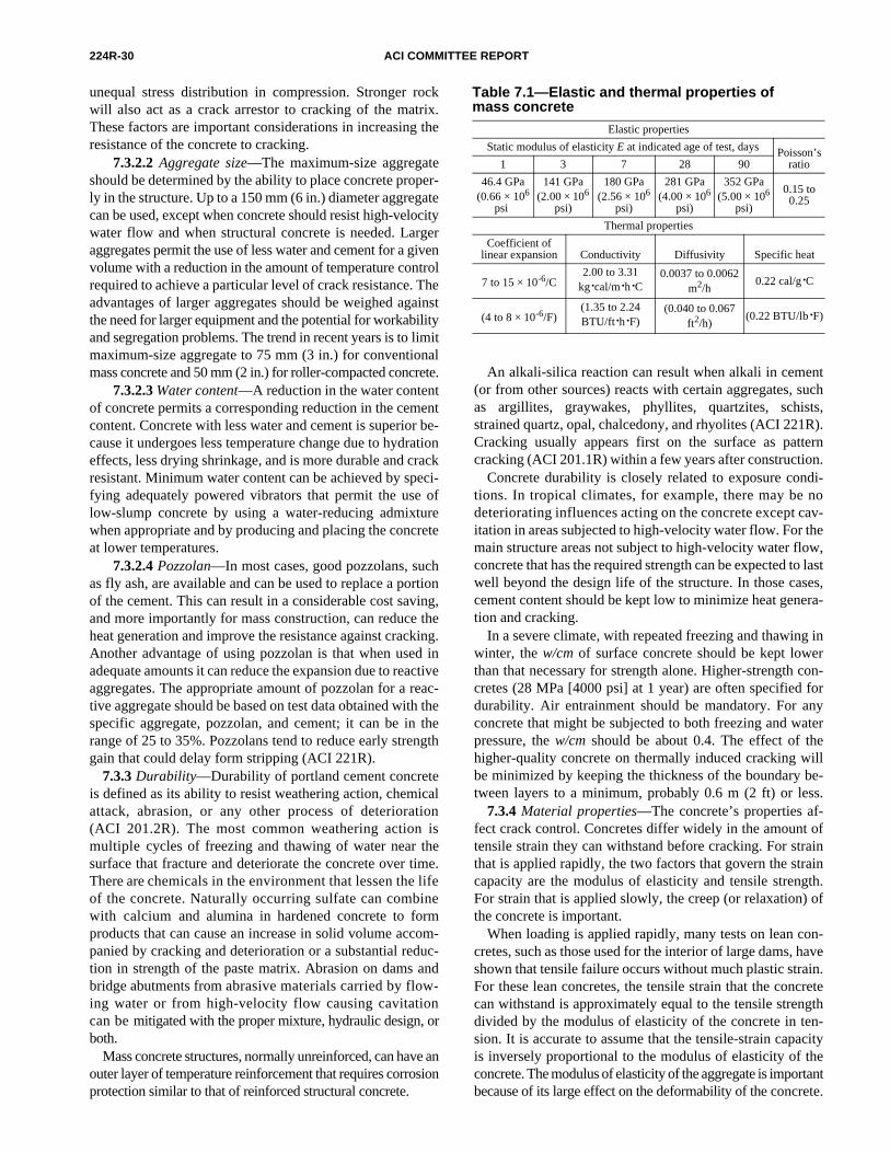
224R-30 ACI COMMITTEE REPORT
unequal stress distribution in compression. Stronger rockwill also act as a crack arrestor to cracking of the matrix.These factors are important considerations in increasing theresistance of the concrete to cracking.
7.3.2.2 Aggregate size—The maximum-size aggregateshould be determined by the ability to place concrete proper-ly in the structure. Up to a 150 mm (6 in.) diameter aggregatecan be used, except when concrete should resist high-velocitywater flow and when structural concrete is needed. Largeraggregates permit the use of less water and cement for a givenvolume with a reduction in the amount of temperature controlrequired to achieve a particular level of crack resistance. Theadvantages of larger aggregates should be weighed againstthe need for larger equipment and the potential for workabilityand segregation problems. The trend in recent years is to limitmaximum-size aggregate to 75 mm (3 in.) for conventionalmass concrete and 50 mm (2 in.) for roller-compacted concrete.
7.3.2.3 Water content—A reduction in the water contentof concrete permits a corresponding reduction in the cementcontent. Concrete with less water and cement is superior be-cause it undergoes less temperature change due to hydrationeffects, less drying shrinkage, and is more durable and crackresistant. Minimum water content can be achieved by speci-fying adequately powered vibrators that permit the use oflow-slump concrete by using a water-reducing admixturewhen appropriate and by producing and placing the concreteat lower temperatures.
7.3.2.4 Pozzolan—In most cases, good pozzolans, suchas fly ash, are available and can be used to replace a portionof the cement. This can result in a considerable cost saving,and more importantly for mass construction, can reduce theheat generation and improve the resistance against cracking.Another advantage of using pozzolan is that when used inadequate amounts it can reduce the expansion due to reactiveaggregates. The appropriate amount of pozzolan for a reac-tive aggregate should be based on test data obtained with thespecific aggregate, pozzolan, and cement; it can be in therange of 25 to 35%. Pozzolans tend to reduce early strengthgain that could delay form stripping (ACI 221R).
7.3.3 Durability—Durability of portland cement concreteis defined as its ability to resist weathering action, chemicalattack, abrasion, or any other process of deterioration(ACI 201.2R). The most common weathering action ismultiple cycles of freezing and thawing of water near thesurface that fracture and deteriorate the concrete over time.There are chemicals in the environment that lessen the lifeof the concrete. Naturally occurring sulfate can combinewith calcium and alumina in hardened concrete to formproducts that can cause an increase in solid volume accom-panied by cracking and deterioration or a substantial reduc-tion in strength of the paste matrix. Abrasion on dams andbridge abutments from abrasive materials carried by flow-ing water or from high-velocity flow causing cavitationcan be mitigated with the proper mixture, hydraulic design, orboth.
Mass concrete structures, normally unreinforced, can have anouter layer of temperature reinforcement that requires corrosionprotection similar to that of reinforced structural concrete.
An alkali-silica reaction can result when alkali in cement(or from other sources) reacts with certain aggregates, suchas argillites, graywakes, phyllites, quartzites, schists,strained quartz, opal, chalcedony, and rhyolites (ACI 221R).Cracking usually appears first on the surface as patterncracking (ACI 201.1R) within a few years after construction.
Concrete durability is closely related to exposure condi-tions. In tropical climates, for example, there may be nodeteriorating influences acting on the concrete except cav-itation in areas subjected to high-velocity water flow. For themain structure areas not subject to high-velocity water flow,concrete that has the required strength can be expected to lastwell beyond the design life of the structure. In those cases,cement content should be kept low to minimize heat genera-tion and cracking.
In a severe climate, with repeated freezing and thawing inwinter, the w/cm of surface concrete should be kept lowerthan that necessary for strength alone. Higher-strength con-cretes (28 MPa [4000 psi] at 1 year) are often specified fordurability. Air entrainment should be mandatory. For anyconcrete that might be subjected to both freezing and waterpressure, the w/cm should be about 0.4. The effect of thehigher-quality concrete on thermally induced cracking willbe minimized by keeping the thickness of the boundary be-tween layers to a minimum, probably 0.6 m (2 ft) or less.
7.3.4 Material properties—The concrete’s properties af-fect crack control. Concretes differ widely in the amount oftensile strain they can withstand before cracking. For strainthat is applied rapidly, the two factors that govern the straincapacity are the modulus of elasticity and tensile strength.For strain that is applied slowly, the creep (or relaxation) ofthe concrete is important.
When loading is applied rapidly, many tests on lean con-cretes, such as those used for the interior of large dams, haveshown that tensile failure occurs without much plastic strain.For these lean concretes, the tensile strain that the concretecan withstand is approximately equal to the tensile strengthdivided by the modulus of elasticity of the concrete in ten-sion. It is accurate to assume that the tensile-strain capacityis inversely proportional to the modulus of elasticity of theconcrete. The modulus of elasticity of the aggregate is importantbecause of its large effect on the deformability of the concrete.
Table 7.1—Elastic and thermal properties of mass concrete
Elastic properties
Static modulus of elasticity E at indicated age of test, days Poisson’s ratio1 3 7 28 90
46.4 GPa (0.66 × 10⁶
psi)
141 GPa (2.00 × 10⁶
psi)
180 GPa (2.56 × 10⁶
psi)
281 GPa (4.00 × 10⁶
psi)
352 GPa (5.00 × 10⁶
psi)
0.15 to 0.25
Thermal properties
Coefficient oflinear expansion Conductivity Diffusivity Specific heat
7 to 15 × 10-6/C2.00 to 3.31
kg·cal/m·h·C0.0037 to 0.0062
m2/h0.22 cal/g·C
(4 to 8 × 10⁻⁶/F)(1.35 to 2.24 BTU/ft·h·F)
(0.040 to 0.067 ft2/h)
(0.22 BTU/lb·F)

CONTROL OF CRACKING IN CONCRETE STRUCTURES 224R-31
Tensile strength is also important, and for this reason,crushed aggregates are apt to be superior to natural aggregatesfor crack prevention.
7.3.4.1 Modulus of elasticity—This subject is discussed indetail in ACI 207.1R. Table 7.1 shows values of the modulus ofelasticity of a particular concrete after various ages of curing.
7.3.4.2 Crack resistance—The tensile strain that con-crete can withstand varies greatly with the composition ofthe concrete and the strain rate. When strain is appliedslowly, the strain capacity is far greater than when the strain isapplied. Therefore, concrete in the interior of a large mass thatmust cool slowly can undergo a large strain before cracking.If concrete contains rough-textured aggregate with smallmaximum size, the strain capacity will be high. There is anoptimum, however, with respect to aggregate size. Concretewith smaller aggregates requires more cement for a givenstrength. This results in more heat, a higher maximum tem-perature, and greater subsequent strain due to cooling.Therefore, these effects can offset the strain increase devel-oped from the use of smaller aggregates.
7.3.4.3 Tensile-strain capacity—Tensile-strain capacitytests are performed on plain concrete beams under third-point flexural loading. Relatively large beams, ranging from300 × 300 mm (12 × 12 in.) to 600 × 600 mm (24 × 24 in.) incross section and 160 to 3250 mm (64 to 130 in.) long are of-ten used (Houghton 1976). Strain capacity is determinedfrom these tests under both rapid and slow loading to simulateboth rapid and slow temperature changes in the concrete.Expressed as extreme fiber stresses, the loading rates aregenerally 0.3 MPa/min (40 psi/min) for rapid loading and0.17 MPa/week (25 psi/week) for slow loading.
For rapid loading, the strain can be measured using eithersurface or embedded strain gages or meters (Houk, Borge,and Houghton 1969; Houghton 1976). Embedded meters arebest for long-term tests. The strain can also be determinedfrom deflection measurements. The concrete test beam usedfor determining the strain capacity should be protected bywrapping with an impermeable material during the test toprevent loss of moisture. Testing should be conducted at aconstant temperature for maximum accuracy in measure-ment. Detailed test procedures can be found in Houk, Borge,and Houghton (1969) and McDonald, Bombieh, and Sulli-van (1972). In the preliminary studies of temperature andconstruction control plans for mass concrete projects, approxi-mate methods for estimating tensile-strain capacity underrapid and slow loadings given by Houghton (1976) and Liuand McDonald (1978) can be used.
7.3.4.4 Thermal properties—Thermal diffusitivity andthermal expansion are important in the control of crackingdue to temperature change; their determination is detailed inACI 207.1R. The approximate range of thermal properties isshown in Table 7.1.
The coefficient of thermal expansion is an important prop-erty of concrete. The amount of strain that a temperaturechange will produce is directly proportional to the coefficientof thermal expansion of the concrete. The average coefficientof thermal expansion of mass concrete is about 5 × 10⁻⁶ F(9 × 10⁻⁶ C), but the coefficient can range from 4 to 8 × 10⁻⁶ F
(7 to 15 × 10–6 C). Therefore, in the extreme case where aconcrete has a low tensile strength, a high modulus ofelasticity, a high coefficient of thermal expansion, and itis fully restrained, the concrete can crack when there is arapid drop in temperature of only 6 F (3 C). On the otherhand, some concretes can withstand a quick drop in temperatureof as much as 20 F (10 C), even when fully restrained. Moredata on the thermal expansion of concrete can be found inACI 207.1R and ACI 207.2R.
Tensile stress in mass concrete results mainly from the re-straint of thermal contraction, and to a far lesser degree, fromautogenous shrinkage. Drying shrinkage is important be-cause it can cause shallow cracks to occur at the surfaces.Temperature change is a principal contributor to tensilestrain in mass concrete. Predicting probable strain requiresthe expected temperature, which can be determined if theadiabatic temperature curve for the concrete is known, aswell as the thermal diffusitivity, boundary temperatures, anddimensions. The temperature rise that would occur if therewere no heat loss is defined as adiabatic temperature rise.The finite-element method can be used for predicting thetemperature distribution. The main problem is choosing thecorrect boundary temperatures, which often depend upon theambient air or water temperatures. It is satisfactory to use airtemperatures provided by the National Weather Service. Fordams, measured reservoir temperatures are used. Refer toACI 207.1R for information on other methods for predictingtemperatures in massive concrete.
The heat-producing characteristics of cement play an im-portant role in the temperature rise. ASTM C 150 Type IV,low-heat cement is recommended; however, it usually is notavailable. Type II moderate-heat cement is also recommend-ed, and it usually is available. Pozzolans can be used to re-place a portion of the cement to reduce the peak temperaturedue to the heat of hydration (ACI 207.2R). In some cases,35 to 50% of the cement can be replaced by an equal vol-ume of a suitable pozzolan and still produce the specifiedstrength at 90 days or 1 year. Some of the more common poz-zolans used in massive concrete include calcined clays, di-atomaceous earth, volcanic tuffs and pumicites, and fly ash.The actual type of pozzolan to be used and its appropriate re-placement percentage are determined by test, cost, and avail-ability.
7.3.4.5 Adiabatic temperature rise—ACI 207.1R describestest methods and provides data on adiabatic temperature riseof concretes with a single cement content but with differenttypes of portland cement. Figure 7.1 gives typical adiabatic
curves for Type II cement and various quantities of cementand pozzolan. The data show the effect of pozzolan replace-ment of cement on temperature reduction.7.4—Construction7.4.1 Basic considerations for construction—Mass con-
crete structures are required to be safe, economical, durable,and aesthetically pleasing. Each of these requirements influ-ences the crack resistance. The cost will depend on featuressuch as the best choice of aggregates, adequate but not exces-sive temperature control, and low cement content. Durability
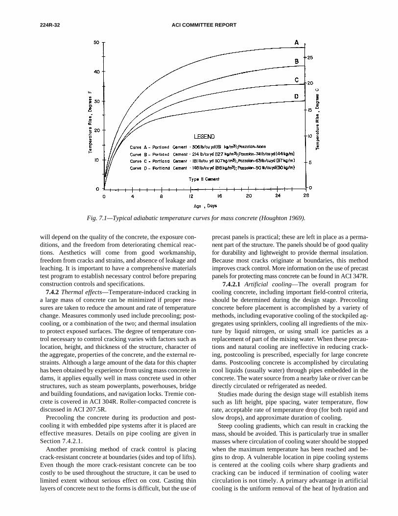
224R-32 ACI COMMITTEE REPORT
Fig. 7.1—Typical adiabatic temperature curves for mass concrete (Houghton 1969).
will depend on the quality of the concrete, the exposure con-ditions, and the freedom from deteriorating chemical reac-tions. Aesthetics will come from good workmanship,freedom from cracks and strains, and absence of leakage andleaching. It is important to have a comprehensive materialstest program to establish necessary control before preparingconstruction controls and specifications.
7.4.2 Thermal effects—Temperature-induced cracking ina large mass of concrete can be minimized if proper mea-sures are taken to reduce the amount and rate of temperaturechange. Measures commonly used include precooling; post-cooling, or a combination of the two; and thermal insulationto protect exposed surfaces. The degree of temperature con-trol necessary to control cracking varies with factors such aslocation, height, and thickness of the structure, character ofthe aggregate, properties of the concrete, and the external re-straints. Although a large amount of the data for this chapterhas been obtained by experience from using mass concrete indams, it applies equally well in mass concrete used in otherstructures, such as steam powerplants, powerhouses, bridgeand building foundations, and navigation locks. Tremie con-crete is covered in ACI 304R. Roller-compacted concrete isdiscussed in ACI 207.5R.
Precooling the concrete during its production and post-cooling it with embedded pipe systems after it is placed areeffective measures. Details on pipe cooling are given inSection 7.4.2.1.
Another promising method of crack control is placingcrack-resistant concrete at boundaries (sides and top of lifts).Even though the more crack-resistant concrete can be toocostly to be used throughout the structure, it can be used tolimited extent without serious effect on cost. Casting thinlayers of concrete next to the forms is difficult, but the use of
precast panels is practical; these are left in place as a perma-nent part of the structure. The panels should be of good qualityfor durability and lightweight to provide thermal insulation.Because most cracks originate at boundaries, this methodimproves crack control. More information on the use of precastpanels for protecting mass concrete can be found in ACI 347R.
7.4.2.1 Artificial cooling—The overall program forcooling concrete, including important field-control criteria,should be determined during the design stage. Precoolingconcrete before placement is accomplished by a variety ofmethods, including evaporative cooling of the stockpiled ag-gregates using sprinklers, cooling all ingredients of the mix-ture by liquid nitrogen, or using small ice particles as areplacement of part of the mixing water. When these precau-tions and natural cooling are ineffective in reducing crack-ing, postcooling is prescribed, especially for large concretedams. Postcooling concrete is accomplished by circulatingcool liquids (usually water) through pipes embedded in theconcrete. The water source from a nearby lake or river can bedirectly circulated or refrigerated as needed.
Studies made during the design stage will establish itemssuch as lift height, pipe spacing, water temperature, flowrate, acceptable rate of temperature drop (for both rapid andslow drops), and approximate duration of cooling.
Steep cooling gradients, which can result in cracking themass, should be avoided. This is particularly true in smallermasses where circulation of cooling water should be stoppedwhen the maximum temperature has been reached and be-gins to drop. A vulnerable location in pipe cooling systemsis centered at the cooling coils where sharp gradients andcracking can be induced if termination of cooling watercirculation is not timely. A primary advantage in artificialcooling is the uniform removal of the heat of hydration and
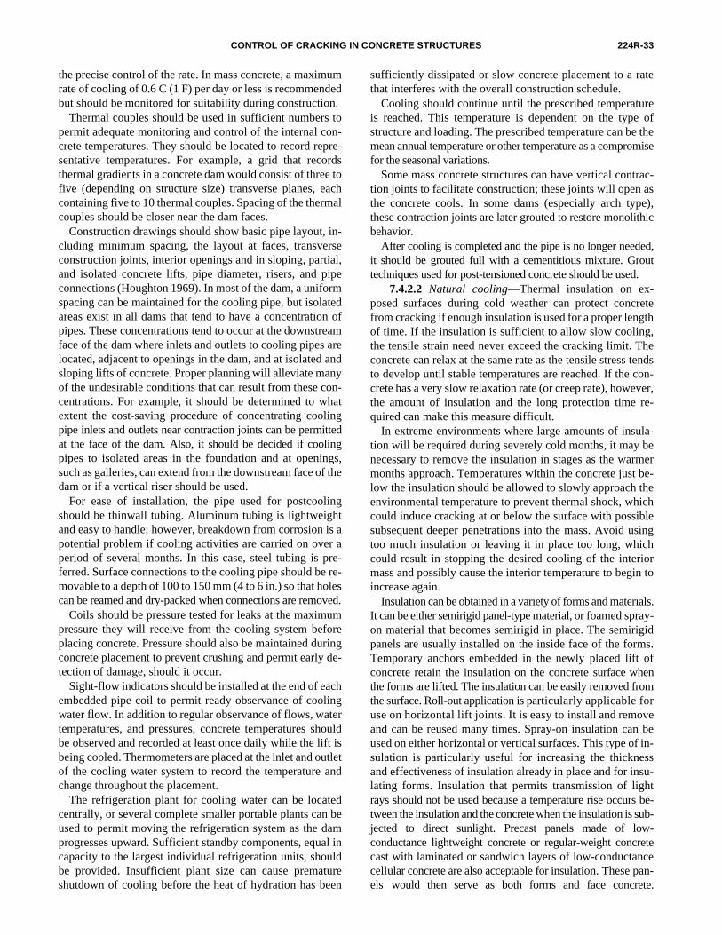
CONTROL OF CRACKING IN CONCRETE STRUCTURES 224R-33
the precise control of the rate. In mass concrete, a maximumrate of cooling of 0.6 C (1 F) per day or less is recommendedbut should be monitored for suitability during construction.
Thermal couples should be used in sufficient numbers topermit adequate monitoring and control of the internal con-crete temperatures. They should be located to record repre-sentative temperatures. For example, a grid that recordsthermal gradients in a concrete dam would consist of three tofive (depending on structure size) transverse planes, eachcontaining five to 10 thermal couples. Spacing of the thermalcouples should be closer near the dam faces.
Construction drawings should show basic pipe layout, in-cluding minimum spacing, the layout at faces, transverseconstruction joints, interior openings and in sloping, partial,and isolated concrete lifts, pipe diameter, risers, and pipeconnections (Houghton 1969). In most of the dam, a uniformspacing can be maintained for the cooling pipe, but isolatedareas exist in all dams that tend to have a concentration ofpipes. These concentrations tend to occur at the downstreamface of the dam where inlets and outlets to cooling pipes arelocated, adjacent to openings in the dam, and at isolated andsloping lifts of concrete. Proper planning will alleviate manyof the undesirable conditions that can result from these con-centrations. For example, it should be determined to whatextent the cost-saving procedure of concentrating coolingpipe inlets and outlets near contraction joints can be permittedat the face of the dam. Also, it should be decided if coolingpipes to isolated areas in the foundation and at openings,such as galleries, can extend from the downstream face of thedam or if a vertical riser should be used.
For ease of installation, the pipe used for postcoolingshould be thinwall tubing. Aluminum tubing is lightweightand easy to handle; however, breakdown from corrosion is apotential problem if cooling activities are carried on over aperiod of several months. In this case, steel tubing is pre-ferred. Surface connections to the cooling pipe should be re-movable to a depth of 100 to 150 mm (4 to 6 in.) so that holescan be reamed and dry-packed when connections are removed.
Coils should be pressure tested for leaks at the maximumpressure they will receive from the cooling system beforeplacing concrete. Pressure should also be maintained duringconcrete placement to prevent crushing and permit early de-tection of damage, should it occur.
Sight-flow indicators should be installed at the end of eachembedded pipe coil to permit ready observance of coolingwater flow. In addition to regular observance of flows, watertemperatures, and pressures, concrete temperatures shouldbe observed and recorded at least once daily while the lift isbeing cooled. Thermometers are placed at the inlet and outletof the cooling water system to record the temperature andchange throughout the placement.
The refrigeration plant for cooling water can be locatedcentrally, or several complete smaller portable plants can beused to permit moving the refrigeration system as the damprogresses upward. Sufficient standby components, equal incapacity to the largest individual refrigeration units, shouldbe provided. Insufficient plant size can cause prematureshutdown of cooling before the heat of hydration has been
sufficiently dissipated or slow concrete placement to a ratethat interferes with the overall construction schedule.
Cooling should continue until the prescribed temperatureis reached. This temperature is dependent on the type ofstructure and loading. The prescribed temperature can be themean annual temperature or other temperature as a compromisefor the seasonal variations.
Some mass concrete structures can have vertical contrac-tion joints to facilitate construction; these joints will open asthe concrete cools. In some dams (especially arch type),these contraction joints are later grouted to restore monolithicbehavior.
After cooling is completed and the pipe is no longer needed,it should be grouted full with a cementitious mixture. Grouttechniques used for post-tensioned concrete should be used.
7.4.2.2 Natural cooling—Thermal insulation on ex-posed surfaces during cold weather can protect concretefrom cracking if enough insulation is used for a proper lengthof time. If the insulation is sufficient to allow slow cooling,the tensile strain need never exceed the cracking limit. Theconcrete can relax at the same rate as the tensile stress tendsto develop until stable temperatures are reached. If the con-crete has a very slow relaxation rate (or creep rate), however,the amount of insulation and the long protection time re-quired can make this measure difficult.
In extreme environments where large amounts of insula-tion will be required during severely cold months, it may benecessary to remove the insulation in stages as the warmermonths approach. Temperatures within the concrete just be-low the insulation should be allowed to slowly approach theenvironmental temperature to prevent thermal shock, whichcould induce cracking at or below the surface with possiblesubsequent deeper penetrations into the mass. Avoid usingtoo much insulation or leaving it in place too long, whichcould result in stopping the desired cooling of the interiormass and possibly cause the interior temperature to begin toincrease again.
Insulation can be obtained in a variety of forms and materials.It can be either semirigid panel-type material, or foamed spray-on material that becomes semirigid in place. The semirigidpanels are usually installed on the inside face of the forms.Temporary anchors embedded in the newly placed lift ofconcrete retain the insulation on the concrete surface whenthe forms are lifted. The insulation can be easily removed fromthe surface. Roll-out application is particularly applicable foruse on horizontal lift joints. It is easy to install and removeand can be reused many times. Spray-on insulation can beused on either horizontal or vertical surfaces. This type of in-sulation is particularly useful for increasing the thicknessand effectiveness of insulation already in place and for insu-lating forms. Insulation that permits transmission of lightrays should not be used because a temperature rise occurs be-tween the insulation and the concrete when the insulation is sub-jected to direct sunlight. Precast panels made of low-conductance lightweight concrete or regular-weight concretecast with laminated or sandwich layers of low-conductancecellular concrete are also acceptable for insulation. These pan-els would then serve as both forms and face concrete.
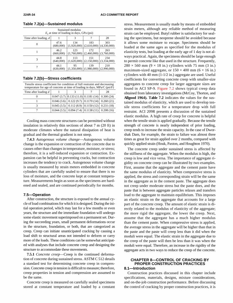
224R-34 ACI COMMITTEE REPORT
CHAPTER 8—CONTROL OF CRACKING BY PROPER CONSTRUCTION PRACTICES
8.1—IntroductionConstruction practices discussed in this chapter include
specifications, materials, designs, mixture considerations,and on-the-job construction performance. Before discussingthe control of cracking by proper construction practices, it is
Cooling mass concrete structures can be permitted withoutinsulation in relatively thin sections of about 7 m (20 ft) inmoderate climates where the natural dissipation of heat isgradual and the thermal gradient is not steep.
7.4.3 Autogenous volume change—Autogenous volumechange is the expansion or contraction of the concrete due tocauses other than changes in temperature, moisture, or stress;therefore, it is a self-induced expansion or contraction. Ex-pansion can be helpful in preventing cracks, but contractionincreases the tendency to crack. Autogenous volume changeis usually measured by strain meters embedded in concretecylinders that are carefully sealed to ensure that there is noloss of moisture, and the concrete kept at constant tempera-ture. Measurements begin as soon as the specimens are hard-ened and sealed, and are continued periodically for months.
7.5—OperationAfter construction, the structure is exposed to the annual cy-
cle of load combinations for which it is designed. During the ini-tial operation period, which may last for a few months or evenyears, the structure and the immediate foundation will undergosome elastic movement superimposed on a permanent set. Dur-ing the succeeding years, small permanent deformations occurin the structure, foundation, or both, that are categorized ascreep. Creep can initiate unanticipated cracking by causing aload shift to structural areas not intended to deform or carrymore of the loads. These conditions can be somewhat anticipat-ed with analyses that include concrete creep and designing thestructure to accommodate these movements.
7.5.1 Concrete creep—Creep is the continued deforma-tion of concrete during sustained stress. ASTM C 512 detailsa standard test for determining concrete creep in compres-sion. Concrete creep in tension is difficult to measure; therefore,creep properties in tension and compression are assumed tobe the same.
Concrete creep is measured on carefully sealed specimensstored at constant temperature and loaded by a constant
Table 7.2(a)—Sustained modulusSustained modulus
Es at time of loading in days, GPa (psi)
Time after loading, d 1 3 7 28
0 47.6 (680,000)
134 (1,920,000)
183 (2,610,000)
303 (4,330,000)
1 46.2 (660,000)
123 (1,760,000)
172 (2,460,000)
263 (3,760,000)
3 44.8 (640,000)
113 (1,620,000)
151 (2,150,000)
234 (3,334,000)
7 44.1 (630,000)
95 (1,350,000)
139 (1,980,000)
210 (2,990,000)
Table 7.2(b)—Stress coefficientsTensile stress coefficient for condition of full restraint and decreasing temperature for age of concrete at time of loading in days, MPa/C (psi/F)
Time after loading d 1 3 7 28
0 0.047 (3.7) 0.133 (11.0) 0.1181 (14) 0.300 (24)
1 0.046 (3.6) 0.122 (9.7) 0.1170 (14) 0.260 (21)
3 0.045 (3.5) 0.112 (8.9) 0.1150 (12) 0.231 (18)
7 0.044 (3.5) 0.094 (7.4) 0.1138 (11) 0.208 (16)
stress. Measurement is usually made by means of embeddedstrain meters, although any reliable method of measuringstrain can be employed. Butyl rubber is satisfactory for seal-ing the specimens, but neoprene should be avoided becauseit allows some moisture to escape. Specimens should beloaded at the same ages as specified for the modulus ofelasticity tests, but loading at the early age of 1 day is not al-ways practical. Again, the specimens should be large enoughto permit concrete like that used in the structure. Frequently,280 × 560 mm (9 × 18 in.) cylinders with 75 mm (3 in.)maximum-sized aggregate, or 150 × 400 mm (6 × 16 in.)cylinders with 40 mm (1-1/2 in.) aggregate are used. Usefulcoefficients for converting concrete creep with smaller-sizeaggregates to concrete creep for larger aggregate sizes arefound in ACI SP-9. Figure 7.2 shows typical creep data
obtained from laboratory investigations (McCoy, Thorton, andAllgood 1964). Table 7.2 indicates the values for the sus-tained modulus of elasticity, which are used to develop ten-sile stress coefficients for a temperature drop with fullrestraint. ACI 209R presents a discussion of the sustainedelastic modulus. A high rate of creep for concrete is helpfulwhen the tensile strain is applied gradually. Because the tensilestrength of concrete is nearly independent of prior loading,creep tends to increase the strain capacity. In the case of Dwor-shak Dam, for example, the strain to failure was almost threetimes as great for strain applied over 2 months, compared withquickly applied strain (Houk, Paxton, and Houghton 1970).The concrete creep under sustained stress is affected bythe stiffness of the aggregate. When the modulus is high, thecreep is low and vice versa. The importance of aggregate ri-gidity on concrete creep can be illustrated by two examples.First, assume that the aggregate and the cement paste havethe same modulus of elasticity. When compressive stress isapplied, the stress and corresponding strain will be the samein the aggregate as in the cement paste. The aggregate doesnot creep under moderate stress but the paste does, and thepaste that is between aggregate particles relaxes and transfersload to the aggregate to maintain equilibrium. This imposesan elastic strain on the aggregate that accounts for a largepart of the concrete creep. The amount of elastic strain is di-rectly related to the modulus of elasticity of the aggregate;the more rigid the aggregate, the lower the creep. Next,assume that the aggregate has a much higher modulusthan the cement paste. When compressive stress is applied,the average stress in the aggregate will be higher than that inthe paste and the paste will creep less than it did when themoduli were equal. The elastic strain in the aggregate due tothe creep of the paste will then be less than it was when themoduli were equal. Therefore, an increase in the rigidity of theaggregate acts in two ways to reduce the creep of the concrete.
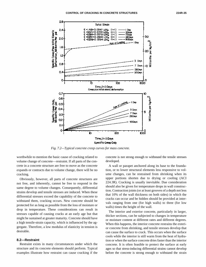
CONTROL OF CRACKING IN CONCRETE STRUCTURES 224R-35
Fig. 7.2—Typical concrete creep curves for mass concrete.
worthwhile to mention the basic cause of cracking related tovolume change of concrete—restraint. If all parts of the con-crete in a concrete structure are free to move as the concreteexpands or contracts due to volume change, there will be nocracking.
Obviously, however, all parts of concrete structures arenot free, and inherently, cannot be free to respond in thesame degree to volume changes. Consequently, differentialstrains develop and tensile stresses are induced. When thesedifferential stresses exceed the capability of the concrete towithstand them, cracking occurs. New concrete should beprotected for as long as possible from the loss of moisture ordrop in temperature. These considerations can result instresses capable of causing cracks at an early age but thatmight be sustained at greater maturity. Concrete should havea high tensile-strain capacity, which is influenced by the ag-gregate. Therefore, a low modulus of elasticity in tension isdesirable.
8.2—RestraintRestraint exists in many circumstances under which the
structure and its concrete elements should perform. Typicalexamples illustrate how restraint can cause cracking if the
concrete is not strong enough to withstand the tensile stressesdeveloped.
A wall or parapet anchored along its base to the founda-tion, or to lower structural elements less responsive to vol-ume changes, can be restrained from shrinking when itsupper portions shorten due to drying or cooling (ACI224.3R). Cracking is usually inevitable. Due considerationshould also be given for temperature drops in wall construc-tion. Contraction joints (or at least grooves of a depth not lessthat 10% of the wall thickness on both sides) in which thecracks can occur and be hidden should be provided at inter-vals ranging from one (for high walls) to three (for lowwalls) times the height of the wall.
The interior and exterior concrete, particularly in larger,thicker sections, can be subjected to changes in temperatureor moisture content at different rates and different degrees.When this happens, the interior concrete restrains the exteri-or concrete from shrinking, and tensile stresses develop thatcan cause the surface to crack. This occurs when the surfacecools while the interior is still warm from the heat of hydra-tion or when the surface concrete dries faster than the interiorconcrete. It is often feasible to protect the surface at earlyages so that stress-inducing differential strains cannot developbefore the concrete is strong enough to withstand the strain
224R-36 ACI COMMITTEE REPORT
without cracking. Reinforcement provided for both thermalcontraction and drying shrinkage can only partially restrainthe contraction of surface concrete, but more and narrowercracks can result.
Restraint can occur at changes in sections because of dif-ferences in temperature or drying shrinkage in the two sec-tions. If feasible, a contraction joint can be used to relieve therestraint. Restraint of flatwork results from anchoring slabreinforcements in perimeter concrete footings. When a slabis free to shrink from all sides toward its center, there is min-imal cracking. Contraction joints and perimeter supportsshould be designed accordingly.
Walls, slabs, and tunnel linings placed against the irregularsurface of a rock excavation are restrained from movingwhen the surface expands or contracts in response to changesin temperature or moisture content. Closely spaced contractionjoints or deep grooves should be provided to hide the cracksthat would disfigure such surfaces. In tunnel linings, the con-traction in the first few weeks is primarily thermal, and theuse of cold concrete 10 C (50 F) can reduce cracking materi-ally. By the time drying is significant, the concrete lining hasa greater tensile strain capacity and therefore is able to resistshrinkage cracking. Circumferential cracks in tunnel liningsand other cast-in-place concrete conduits and pipe lines,however, can be greatly reduced in number and width if abulkhead is used to prevent air movement through the tunnel,and shallow ponds of water are placed in the invert as soonas possible after placing the lining. They should remain thereuntil the tunnel is put into service (USBR 1981). The con-crete can become much stronger in the humid environmentand will be better able to resist shrinkage-induced tensilestresses if allowed to dry in service. If the tunnel carries wa-ter, there will be no further drying shrinkage.
The previous examples indicate that many crack-controlprocedures should be considered during design. While prop-er construction performance can contribute a great deal (aswill be discussed), the contractor cannot be expected to usethe best procedures unless these procedures are included inthe contract documents.
8.3—Shrinkage8.3.1 Effect of water content—As shown in Fig 3.5, concrete
drying shrinkage is proportional to mixture water content. Theuse of the lowest practical slump adds in the control of crack-ing. Of major importance is the selection of mixture propor-tions that require the least amount of water for the desiredconcrete strength and durability. This means avoiding over-sanded mixtures, using the largest maximum aggregate sizepractical, and using aggregate with the most favorable shapeand grading conducive to workability. Also use a well-grad-ed sand with a minimum of fines passing the 100 mesh andfree of clay, such that its sand equivalent value is not lessthan 80% (AASHTO T 176). Shrinkage tends to be propor-tional to the total paste volume in the mixture.
8.3.2 Surface drying—Surface drying will occur exceptwhen the surface is submerged or below grade. Dryingshrinkage strains of up to 600 × 10–6 or more are likely. Theamount of shrinkage cracking depends on factors such as
surface dryness; mixture proportions, especially mixing wa-ter; the character and degree of restraint; and the extensibili-ty (tensile-strain capacity) of the concrete. The extensibilityrepresents how much the concrete can be strained withoutexceeding its tensile strength and is the sum of creep pluselastic-strain capacity. The latter is largely related to thecomposition of the aggregate and can vary widely. Typical-ly, some concretes of highly quartzitic gravels have a lowstrain capacity and a high modulus of elasticity. Concreteswith a low strain capacity are much more sensitive to shrink-age due to drying (and to a decrease in temperature) and willbe subjected to a greater amount of cracking.
A prime objective of crack-control procedures is to keepthe concrete wet as long as possible so that the concrete willhave time to develop more strength to resist cracking forces.As described in Chapter 3 and Carlson (1938), there aresome cases where prolonged moist curing is not beneficial.The importance of moist curing will vary with the weatherand the time of year. Cold concrete (below 10 C [50 F]) driesvery slowly, provided the relative humidity is above 40%. Atsome depth, concrete loses moisture slowly. Where surfacedrying can be rapid, more care should be devoted to uninter-rupted curing to improve surface strength. Cracking will befurther reduced by creep if the surface is prevented from dryingquickly at the end of the curing period. To accomplish slowdrying, wet curing should remain for several days withoutwetting after the specified curing period (preferably 7 to10 days) until the cover and the concrete under it appearto be dry. If these procedures are required to be used, theyshould be included in project contract documents.
8.3.3 Plastic shrinkage—Objectionable plastic shrinkagecracks commonly occur in the surfaces of floors and slabswhen job conditions are so dry that moisture is removedfrom the concrete surface faster than it is replaced by bleed-water. These cracks occur before the start of curing and canoccur either before or after final finishing. As the moisture isremoved, the surface concrete contracts, resulting in tensilestresses in the weak, stiffening, plastic concrete that causeshort random cracks in the surface. These cracks are usuallywide at the surface but only a few millimeters (inches) indepth, although full-depth cracks can occur in pavements.The cracks range from a few millimeters (inches) to a fewmeters (feet) in length and are a few millimeters (inches) to2/3 m (2 ft) apart.
Sometimes plastic shrinkage cracks appear early enoughto be removed in later floating or troweling operations.When this occurs, it is advisable to postpone these operationsas long as possible to get their maximum benefit without therecurrence of cracking.
In other cases, early floating can destroy the growing ten-sion by reworking the surface mortar and prevent plasticcracking. At the first appearance of cracking while theconcrete is still responsive, a vigorous effort should bemade to close the cracks by tamping or beating with a float.If firmly closed, they are unlikely to reappear. They can,however, reappear if they are merely troweled over. In anyevent, curing should be started as soon as possible.
CONTROL OF CRACKING IN CONCRETE STRUCTURES 224R-37
Plastic shrinkage cracking is most likely when environ-mental conditions, concrete temperature, and mixture propor-tions combine to cause a rapid loss of available surfacemoisture. These conditions can develop in either hot or coldweather when low humidity and high wind speed combinewith a warm concrete surface temperature. Project specifica-tions should stipulate that effective moisture-control precau-tions should be taken to prevent a serious loss of surfacemoisture under such conditions. Principal among these pre-cautions are the use of fog (not spray) nozzles to maintain asheen of moisture on the surface between the finishing oper-ations. Plastic sheeting can be rolled on and off before andafter floating, preferably exposing only the area beingworked on at that time. Less effective but helpful precautionsinclude sprayed monomolecular films that inhibit evapora-tion. Windbreaks are helpful; therefore, it is desirable toschedule flatwork after the walls are erected (ACI 305R;ACI 302.1R).
Plastic shrinkage cracking is associated with the rate lossof surface moisture relative to the replenishment rate ofmoisture by bleeding. As a result, the tolerable rate of mois-ture loss is significantly affected by the rate of bleeding. Fur-ther, the rate of moisture loss from the surface of concrete isdriven by a combination of factors that include air tempera-ture, concrete temperature, relative humidity of the air abovethe concrete, degree of saturation of the surface of the con-crete (amount of bleedwater), and the wind velocity at theconcrete surface.
The rate of evaporation can be greater during cold-weather-concreting conditions than during hot weather, particularlywhen the concrete has been heated, the air is cold and dry,and the wind speed is high. The reason for this is that thethermal driving force for surface evaporation is the differ-ence between air and concrete temperature. When the con-crete is warmer than the air, evaporation is favored; this isdependent on humidity and wind speed as well.
Other helpful practices that can counteract the excessiveloss of surface moisture are using a well-dampened sub-grade, cooling the aggregates by dampening and shadingthem, and using cold mixing water or chipped ice as mixingwater to lower the fresh concrete temperature.
8.3.4 Surface cooling—Surface cooling will typicallyshrink the surface of unrestrained concrete about 10 × 10–6 C(5.5 × 10⁻⁶ F) as temperature decreases. This amounts to 9 mmin a 30 m length with a drop of 30 C (1/3 in. in 100 ft lengthwith a drop of 50 F). The amount of shrinkage deformationis reduced by restraint and creep but tensile stresses result.The earlier the age and the slower the rate at which coolingor drying occur, the lower the tensile stresses will be. The in-fluence of creep decreases the effective modulus of concreteloaded at early ages and allows more extensibility.
In ordinary concrete work, winter protection required forthe development of adequate strength will prevent the mostcritical effects of cooling. Contraction joints for control ofshrinkage cracking will also control cracking due to drops insurface temperature. In addition to Chapter 7 of this report,Chapters 4 and 5 of ACI 207.1R discuss temperature con-trols for mass concrete to minimize the early temperature
differences between the interior and the exterior concrete.Primarily, these controls lower the interior temperature risecaused by the heat of hydration by using minimum cementcontent, pozzolans to replace a portion of the cement, water-reducing admixtures, air-entrainment, large aggregate sizes,low slump, and chipped ice for mixing water to maintain thetemperature of the fresh concrete as close to 10 C (50 F) aspossible. At no time should forms be removed to exposewarm surfaces to low temperatures. As mentioned in Section8.3.2, the extensibility or strain the concrete will withstandbefore tensile failure is a function of the aggregate andshould be evaluated, especially on larger projects. What ap-plies to one project will not necessarily apply to another.
8.4—SettlementSettlement or subsidence cracks develop while concrete is
in the plastic stage after the initial consolidation. Settlementcracks are the natural result of heavy solids settling in a liq-uid medium. Settlement cracks occur along rigidly supportedelements, such as horizontal reinforcement, form ties, orembedments. Sometimes concrete will adhere to the forms.A crack will appear at these locations if the forms are hot atthe top or are partially absorbent. Cracks often appear in hor-izontal construction joints and in bridge deck slabs over re-inforcing or form ties with only a few inches of cover (about75 to 125 mm [3 to 5 in.]). Settlement cracks in bridge deckscan be reduced by increasing the concrete cover along withmixture proportioning that minimizes bleeding and settle-ment. Properly executed late revibration can be used to closesettlement cracks and improve the quality and appearance ofthe concrete in the upper portion of such placements, eventhough settlement has taken place and slump has been lost(ACI 309R). Use of a low-slump concrete is also recom-mended to help prevent settlement cracks in bridge decksand slabs.
8.5—Construction A great deal can be done during construction to minimize
cracking. The individual project specifications should bespecific with regard to actions that should be taken to copewith extremes of nature and to make enforceable requirements.
8.5.1 Concrete aggregates—The aggregates should be se-lected to make concrete of high-strain capacity, if reasonablyavailable. It is important that fine and coarse aggregates beclean and free of unnecessary fine material, particularlyclays. The fine aggregate should have a sand equivalent val-ue greater than 80% and should be verified frequently(AASHTO T 176). The sand should have sufficient time instorage for the moisture content to stabilize at a level of lessthan 7% on an oven-dry basis.
8.5.2 Shrinkage-compensating cement—Shrinkage-compen-sating cement can be used to compensate for shrinkage inrestrained elements or elements with the minimum shrink-age reinforcement required by ACI 318. The principal prop-erty of these cements is that the expansion induced in theconcrete while setting and hardening is designed to offset thenormal drying shrinkage. With correct usage (particularlywith early and ample water curing required for maximum
224R-38 ACI COMMITTEE REPORT
expansion), the distance between joints can sometimes betripled without increasing the level of shrinkage cracking. De-tails on the types and the correct usage of shrinkage-compen-sating cements are given in Section 3.6 and ACI 223.
8.5.3 Handling and batching—Aggregates should be han-dled so as to avoid contamination, segregation, and break-age. Handling and batching is best done by finish screeningand rinsing coarse aggregate into their various sizes andplacing them in the appropriate bins at the batch plant. Everyeffort should be made to uniformly batch and mix the con-crete so that there will be a minimum of variation in slumpand workability, which invariably lead to demands for agreater margin of workability.
8.5.4 Cold concrete—In mass concrete structures, reduc-ing water and cement contents to a practical minimum andusing cold concrete will reduce temperature differentials thatcause cracking. Less mixing water reduces drying shrinkage.In warm weather, cold concrete reduces slump loss, increasespumpability, and improves the response to vibration. Chippedice can be substituted for all or a part of the batched mixingwater. In cold weather, concrete is naturally cold, and everyeffort should be made to use it as cold as possible without in-viting damage from freezing. It is pointless to try protectingsurfaces, edges, and corners by placing needlessly warmconcrete in cold weather. These vulnerable parts require pro-tection by insulation or protective enclosures (ACI 306R).
8.5.5 Revibration—When done as late as the formed con-crete will respond to the vibrator, revibration can eliminatecracks and checks where something rigidly fixed in theplacement prevents a part of the concrete from settling withthe rest of it. Settlement cracks are most apparent in the up-per part of wall and column placements where revibrationcan be readily used. Deep revibration corrects cracks causedby differential settlement around blockout and windowforms and where slabs and walls are placed monolithically(ACI 309R).
8.5.6 Finishing—Proper flatwork finishing can make adifference in many types of cracking (ACI 302.1R). Low-slump concrete should be used. More than a 75 mm (3 in.)slump is rarely necessary, except in hot weather, where bothslump and moisture are lost quite rapidly. Finishing shouldnot be done in the presence of surface water. Precautions(Section 8.3.3) should be taken to prevent plastic shrinkage.Any required marking and grooving should be carefully cutto the specified depth. Curing should be promptly conducted.
8.5.7 Curing and protection—Concrete should be broughtto a level of adequate strength and protected from low tem-peratures and drying conditions that would otherwise causecracking. The curing and protection should not be discontin-ued abruptly. If the new concrete is given a few days to grad-ually dry or cool, creep can reduce the possibility of crackingwhen the curing and protection are fully discontinued.Subsequent application of a curing compound after initialcuring will slow drying out.
8.5.8 Miscellaneous—Some items normally covered inproject specifications (or which should be covered whereappropriate) require special attention during constructionbecause of their potential effects on cracking.
• Reinforcement and embedments should be firmly posi-tioned with the designated thickness of cover to preventcorrosion, expansion, and cracking;
• Concrete should not be placed against hot reinforce-ment or forms;
• Formwork support should be both strong and stiffenough to be free of early failures and distortion caus-ing cracking;
• Subgrade and other supports should not settle unevenly,which may lead to cracking due to overstress in thestructure;
• Calcium chloride should not be used if steel reinforcementis present. If acceleration in setting or strength gain isneeded, additional cement, hot water, or a nonchlorideaccelerator should be used;
• Special care is needed in handling precast units to pre-vent overstress due to handling. Pickup points and rig-ging should be considered;
• Avoid the use of unvented salamanders in cold weather(ACI 306R) or gasoline-operated equipment whereventilation is not adequate. These will increase the dan-ger of carbonation, causing shrinkage and surfacecracking;
• Contraction joints should not be omitted and groovesshould be of sufficient depth and well within the maxi-mum permitted spacing. In hot weather or arid environ-ments, contraction joints should be installed in the freshconcrete as inserts or saw-cut when the concrete is hardenough not to be torn or damaged by the blade;
• Reactive elements of coarse aggregate should be neu-tralized through the use of low-alkali cement, suitablepozzolans, or both. Certain cherts and other expansiveaggregates can cause cracks and popouts. Project speci-fications should cover these aggregate properties andthe cleanliness of these aggregates; and
• Correct amounts of entrained air should be used andmonitored to prevent cracking due to freezing andthawing and exposure to deicing salts.
8.6—Specifications to minimize drying shrinkageActions during construction to obtain the lowest possible
change in volume of the concrete should be supported by thespecifications. Unless bids are taken on this basis, the con-tractors cannot be expected to provide other than ordinarymaterials, mixtures, and procedures. The following itemsshould be carefully spelled out in the project specifications.
8.6.1 Concrete materials—Cement should be ASTM C150 Types I, II, V, ASTM C 595 Type IS, or ASTM C 845for expansive hydraulic cement. Use special care if Type IIIcement is used because of its high rate of heat generation andstrength (and stiffness) development. Recommendation of ACI224 should be followed when using shrinkage-compensatingcement. ASTM C 595 Type IP can also be used. Aggre-gates favorable to low mixing-water content are well graded,well shaped (not elongated, flat, or splintery), with minimumamounts of clay, dirt, and excessive fines. Aggregate shouldconsist of rock types that will produce low-shrinkage con-crete. Utilization of pozzolans and chemical admixtures
CONTROL OF CRACKING IN CONCRETE STRUCTURES 224R-39
should be considered as appropriate. Calcium chloride andother admixtures containing a significant amount of chlorideshould be prohibited.
8.6.2 Concrete mixtures—For the least amount of shrink-age, the mixture proportions should incorporate those factorsthat contribute to the lowest paste content. Use the largestpractical maximum size of aggregate (MSA). The lowestpractical sand content, slump (water content), and mixturetemperature should also be used. Where possible, limit thesmaller-size fractions, that is, 4.75 mm to 9.5 or 20 mm (No.4 to 3/8 or 3/4 in.), of coarse aggregate to half of the total,especially if the aggregate is crushed.
8.6.3 Concrete handling and placing—Equipment(chutes, belts, conveyors, pumps, hoppers, and bucket open-ings) should be capable of working effectively with lowerslump, larger MSA concrete wherever it is appropriate andfeasible to use it. The actions that tend to make a mixturemore pumpable also tend to make the resulting concretemore prone to shrinkage and cracking. The use of pumpingequipment capable of handling mixtures favorable to mini-mize cracking should be required.
Vibrators should be the largest and most powerful that canbe operated in the placement. Upper lifts of formed concretecould be revibrated as late as the running vibrator will pene-trate under its own weight.
8.6.4 Finishing—Finishing should follow the recommen-dations of ACI 302.1R to minimize or avoid surface crack-ing. It is particularly important that flatwork joint grooveshave a depth of at least one-quarter of slab thickness.
8.6.5 Forms—Forms should have ample strength to sus-tain strong vibration of low-slump concretes. Exposingwarm concrete surfaces to fast drying conditions or to lowtemperatures before curing should be avoided during formremoval if drying and thermal shrinkage cracking is to beprevented (ACI 347R).
8.6.6 Contraction joints—Project drawings should includean adequate system of contraction joints to provide forshrinkage. Formed grooves should be constructed in bothsides of parapet, retaining, and other walls at the appropriatedepth and spacing. ACI 224.3R provides useful informationon contraction joints.
8.6.7 Curing and protection—These procedures shouldensure the presence of adequate moisture to sustain hydra-tion in the surface concrete during the early ages of strengthdevelopment. Rapid drying of the surfaces at the conclusionof the specified curing period should be avoided. Providingtime for adjustment and relaxation of restraint-inducedstresses minimizes cracking.
The best curing environment is to keep the concrete con-tinuously wet during the curing period. Water curing shoulduse a wet cover in contact with the concrete surfaces. At theend of the wet curing period, at least 7 days, the cover shouldbe left in place until it and the concrete surface appear to bedry, especially in arid weather.
In less-arid areas and for interiors, the forms will pro-vide adequate curing if exposed surfaces are protectedfrom drying and left in contact with the concrete for atleast 7 days. Thereafter, the forms should be left on with
loosened bolts long enough to allow the concrete surfacesto dry gradually.
If ponding is used for curing in an arid climate, precau-tions such as a properly applied curing compound shouldbe used when ponding is discontinued to avoid quick drying.Because drying is slow and prolonged, a properly appliedcuring compound provides good curing for flatworkplaced on a well-wetted subgrade, and it provides ade-quate curing for formed surfaces. In an arid climate, cur-ing compounds are not adequate for thinner structuralsections. When used on formed surfaces, they should be appliedwhen the surface is still damp but no longer wet (ACI 308).
8.7—ConclusionIt is the responsibility of the engineer to develop effective
designs and clear, specific provisions in project specifica-tions. To ensure both the owner’s and the engineer’s satisfac-tion with the results, the engineer should have the ownerarrange for inspection by either the owner’s personnel, theengineer, or a reliable professional inspection service thatwill ensure that the construction is performed on the samebasis as it was bid. Without the full and firm intent to confirmthe specified character and degree of performance, there is alikelihood that undesirable results will be obtained. Withoutfirm inspection, a quality-control-assurance program, and aclear understanding of the project requirements by thecontractor, it is likely that concrete will contain more waterthan it should. With less water content in the concrete, thefinishing operations can be expedited and the curing processcan start earlier. If properly applied, the procedures discussed inthis chapter can have an effective influence on producing high-quality concrete with minimal cracking.
CHAPTER 9—REFERENCES9.1—Referenced standards and reports
The standards and reports listed as follows were the latesteditions at the time this document was prepared. Becausethese documents are revised frequently, the reader is advisedto contact the proper sponsoring group if it is desired to referto the latest version.
American Association of State Highway and TransportationOfficials (AASHTO)T 176 Plastic Fines In Graded Aggregate and Soils by
Use of the Sand Equivalent Test
American Concrete Institute (ACI)116R Cement and Concrete Terminology201.1 Guide for Making a Condition Survey of Concrete
in Service201.2R Guide to Durable Concrete207.1R Mass Concrete 207.2R Effect of Restraint, Volume Change, and Rein-
forcement on Cracking of Mass Concrete207.4R Cooling and Insulating Systems for Mass Concrete207.5R Roller Compacted Mass Concrete209R Prediction of Creep, Shrinkage, and Temperature
Effects in Concrete Structures

224R-40 ACI COMMITTEE REPORT
212.3R Chemical Admixtures for Concrete221R Guide for Use of Normal Weight and Heavyweight
Aggregates in Concrete221.1R State-of-the-Art Report on Alkali-Aggregate
Reactivity222R Corrosion of Metals in Concrete223 Standard Practice for the Use of Shrinkage-
Compensating Concrete224.3R Joints in Concrete Construction302.1R Guide for Concrete Floor and Slab Construction304R Guide for Measuring, Mixing, Transporting, and
Placing Concrete305R Hot Weather Concreting306R Cold Weather Concreting308 Standard Practice for Curing Concrete309R Guide for Consolidation of Concrete313 Standard Practice for Design and Construction of
Concrete Silos and Stacking Tubes for StoringGranular Materials
318/318R Building Code Requirements for StructuralConcrete and Commentary
340R ACI Design Handbook (SP-17(97))347R Guide to Formwork for Concrete350 Code Requirements For Environmental
Engineering Concrete Structures446.1R Fracture Mechanics of Concrete: Concepts,
Models, and Determination of Material Properties504R Guide to Sealing Joints for Concrete Structures544.2R Measurement of Properties of Fiber-Reinforced
Concrete544.3R Guide for Specifying, Proportioning, Mixing,
Placing, and Finishing Steel Fiber ReinforcedConcrete
544.4R Design Considerations for Steel Fiber ReinforcedConcrete
548R Polymers in Concrete548.1R Guide for the Use of Polymers in ConcreteSP-38 Klein Symposium on Expansive Cement Con-
cretesSP-40 Polymers in ConcreteSP-58 Polymers in ConcreteSP-64 Cedric Wilson Symposium on Expansive Cement
American Society for Testing and Materials (ASTM)C 150 Specification for Portland CementC 845 Specification for Expansive Hydraulic CementE 399 Test Method for Plain-Strain Fracture Toughness
of Metallic Materials
European Committee for Concrete-International Federationof Prestressed Concrete (CEB-FIP)CEB-FIP European Model Code for Concrete Structures
The above publications may be obtained from the followingorganizations:
American Association of State Highway and TransportationOfficials
444 N. Capitol Street NWSuite 225Washington, DC 20001
American Concrete InstitutePO Box 9094Farmington Hills, MI 48333-9094
ASTM100 Barr Harbor DriveWest Conshohocken, PA 19428
CEB-FIPc/o British Cement AssociationCentury HouseTelford AvenueCrowthorne, Berkshire RG45 6YSUnited Kingdom
9.2—Cited referencesAalami, B. O., and Barth, F. G., 1989, “Restraint Cracks
and their Mitigation in Unbonded Post-Tensioned BuildingStructures,” Cracking in Prestressed Concrete Structures,SP-113, G. T. Halvorsen and N. H. Burns, eds., American Con-crete Institute, Farmington Hills, Mich., pp. 157-202.
Abeles, P. W., 1956, “Cracks in Prestressed ConcreteBeams,” Proceedings, 5th IABSE Congress, InternationalAssociation for Bridge and Structural Engineering, Zurich,pp. 707-720.
Abeles, P. W.; Brown, E. L., II; and Morrow, J. W., 1968,“Development and Distribution of Cracks in RectangularPrestressed Beams during Static and Fatigue Loading,”Journal, Prestressed Concrete Institute, V. 13, No. 5, Oct.,pp. 36-51.
ACI Committee 223, 1970, “Expansive Cement Con-cretes: Present State of Knowledge,” ACI JOURNAL, Pro-ceedings V. 67, No. 8, Aug., pp. 583-610.
ACI Committee 224, 1971, “Causes, Mechanism, andControl of Cracking in Concrete,” ACI Bibliography No. 9,American Concrete Institute, Farmington Hills, Mich., 92 pp.
ACI Committee 224, 1972, “Control of Cracking in Con-crete Structures,” ACI JOURNAL, Proceedings V. 69, No. 12,Dec., pp. 717-753.
ACI Committee 224, 1980, “Control of Cracking in Con-crete Structures,” Concrete International: Design and Con-struction, V. 2, No. 10, Oct., pp. 35-76.
ACI Committee 318, 1999, “Discussion of a Report Pub-lished in the November 1998 Issue of Concrete Internation-al, pp. S1-S90,” Concrete International, V. 21, No. 5., May,pp. 318.1-318.49.
Atimtay, E., and Ferguson, P. M., 1973, “Early ChlorideCorrosion of Reinforced Concrete—A Test Report,” ACIJOURNAL, Proceedings V. 70, No. 9, Sept., pp. 606-611.
Attiogbe, E. K., and Darwin, D., 1987, “Submicrocrackingin Cement Paste and Mortar,” ACI Materials Journal, V. 84,No. 6, Nov.-Dec., pp. 491-500.
CONTROL OF CRACKING IN CONCRETE STRUCTURES 224R-41
Attiogbe, E. K., and Darwin, D., 1988, “Strain Due to Sub-microcracking in Cement Paste and Mortar,” ACI MaterialsJournal, V. 85, No. 1, Jan.-Feb., pp. 3-11.
Bascoul, A.; Kharchi, F.; and Maso, J. C., 1987, “Concern-ing the Measurement of the Fracture Energy of a Micro-Con-crete According to Crack Growth in Three Point BendingTests of Notched Beams,” Proceedings, SEM-RILEM Inter-national Conference on Fracture of Concrete and Rock, S. P.Shah and S. E. Swartz, eds., Houston, Tex.
Bate, S. C. C., 1958, “Relative Merits of Plain and De-formed Wires in Prestressed Concrete Beams under Staticand Repeated Loading,” Proceedings, Institution of CivilEngineers (London), V. 10, Aug., pp. 473-502.
Bate, S. C. C., 1963, “A Comparison Between PrestressedConcrete and Reinforced Concrete Beams under RepeatedLoading,” Proceedings, Institution of Civil Engineers(London), V. 24, Mar., pp. 331-358.
Bažant, Z. P., 1979, “Material Behavior under VariousTypes of Loading,” High Strength Concrete, S. P. Shah, ed.,University of Illinois at Chicago, pp. 79-92.
Bažant, Z. P.; Kim, J. K; and Pfeiffer, P., 1986, “Determi-nation of Non-linear Fracture Parameters from Size EffectTests,” Journal of Structural Engineering, ASCE, V. 112,No. 2, Feb., pp. 289-307.
Bažant, Z. P., and Oh, B. H., 1983, “Crack Band Theoryfor Fracture of Concrete,” Materials and Structures,RILEM, V. 16, No. 93, pp. 155-177.
Bažant, Z. P., and Sener, S., 1988, “Size Effect in PulloutTests,” ACI Materials Journal, V. 85, No. 5, May, pp. 347-351.
Bažant, Z. P.; Sener, S.; and Pratt, P. C., 1988, “Size EffectTests of Torsional Failure of Plain and Reinforced ConcreteBeams,” Materials and Structures, V. 21, pp. 425-430.
Bažant, Z. P., and Sun, H. H., 1987, “Size Effect in Diag-onal Shear Failure: Influence of Aggregate Size and Stirrups,”ACI Materials Journal, V. 84, No. 4, Apr., pp. 259-272.
Beckett, D., and Alexandrou, A., 1997, Introduction to Euro-code 2— Design of Concrete Structures, E&FN Spon, 191 pp.
Beeby, A. W., 1978a, “Concrete in the Oceans—Crackingand Corrosion,” Technical Report No. 1, Cement and ConcreteAssociation, London.
Beeby, A. W., 1978b, “Corrosion of Reinforcing Steel inConcrete and Its Relation to Cracking,” The Structural Engi-neer, London, V. 56A, No. 3, Mar., pp. 77-81.
Beeby, A. W., 1983, “Cracking Cover at Corrosion ofReinforcement,” Concrete International: Design andConstruction, V. 5, No. 2, Feb., pp. 35-40.
Bennett, E. W., and Chandrasekhar, C. S., 1971, “Calcula-tion of the Width of Cracks in Class 3 Prestressed Beams,”Proceedings, Institution of Civil Engineers, London, V. 49,July, pp. 333-346.
Bennett, E. W., and Dave, N. J., 1969, “Test Performancesand Design of Concrete Beams with Limited Prestress,” TheStructural Engineer, London, V. 47 No. 12, Dec., pp. 487-496.
Bishara, A. G., 1979, “Latex Modified Concrete BridgeDeck Overlays—Field Performance Analysis,” ReportNo. FHWA/OH/79/004, Federal Highway Administration,Washington D.C., Oct., 97 pp.
Bishara, A. G., and Tantayanondkul, P., 1974, “Use of La-tex in Concrete Bridge Decks,” Report No. EES 435,(ODOT-12-74) Ohio Department of Transportation, OhioState University, Columbus, Ohio.
Brendel, G., and Ruhle, H., 1964, “Tests on Reinforced Con-crete Beams Under Long-Term Loads (Dauerstandvrsuchemit Stahlbetonbalken),” Proceedings, Seventh IABSE Con-gress (Rio de Janeiro, 1964), International Association ofBridge and Structural Engineering, Zurich, Switzerland,pp. 916-922.
Broms, B. B., 1965a, “Technique for Investigation of In-ternal Cracks in Reinforced Concrete Members,” ACI JOUR-
NAL, Proceedings V. 62, No. 1, Jan., pp. 35-44.Broms, B. B., 1965b, “Crack Width and Crack Spacing in
Reinforced Concrete Members,” ACI JOURNAL, Proceed-ings V. 62, No. 10, Oct., pp. 1237-1256.
Brookhaven National Laboratory, 1968, “Concrete Poly-mer Materials,” BNL Report 50134 (T-509).
Brooks, J. J., and Neville, A. M., 1977, “A Comparison ofCreep, Elasticity and Strength of Concrete in Tension and inCompression,” Magazine of Concrete Research, London,V. 29, No. 100, Sept., pp. 131-141.
Bryant, A. H., and Vadhanavikkit, C., 1987, “CreepShrinkage—Size, and Age at Loading Effects,” ACI Materi-als Journal, V. 84, No. 2, Mar.-Apr., pp. 119-123.
Burgess, J. A.; Breen, J. E.; and Poston, R. W., 1989,“Anchorage Zone Cracking of Post-Tensioned BridgeDecks with Closely Spaced Anchors,” Cracking in PrestressedConcrete Structures, SP-113, G. T. Halvorsen and N. H. Burns,eds., American Concrete Institute, Farmington Hills, Mich.,pp. 79-108.
Buyukozturk, O., 1970, “Stress-Strain Response and Frac-ture of a Model of Concrete in Biaxial Loading,” PhD thesis,Cornell University, Ithaca, N.Y., June.
California Department of Transportation, 1963, Report:Effect of Curing on Shrinkage of Concrete.
Carino, N. J., 1977, “Effects of Polymer Impregnation onMortar-Aggregate Bond Strength,” Cement and ConcreteResearch, V. 7, No. 4, July, pp. 439-447.
Carlson, R. W., 1938, “Drying Shrinkage of Concrete asAffected by Many Factors,” Proceedings, ASTM, V. 38,Part II, pp. 419-437.
Carrasquillo, R. L.; Slate, F. O.; and Nilson, A. H., 1981,“Microcracking and Behavior of High Strength ConcreteSubject to Short-Term Loading,” ACI JOURNAL, ProceedingsV. 78, No. 3, May-June, pp. 179-186.
Castro-Montero, S.; Shah S. P., and Miller, R. A., 1990,“Study of Fracture Process in Mortar with Laser HolographicMeasurements,” Proceedings of the NATO Advanced ResearchWorkshop on Toughening Mechanisms in Quasi-BrittleMaterials, Evanston, Ill.
Catalano, D., and Ingraffea, A. R., 1982, “Concrete Frac-ture: A Linear Elastic Fracture Approach,” Department ofStructural Engineering Report, School of Civil and Environ-mental Engineering, Cornell University, Ithaca, N.Y., 161 pp.
Clear, K. C., 1974, “Time to Corrosion of ReinforcingSteel in Concrete Slabs,” Transportation Research RecordNo. 500, Transportation Research Board, pp. 16-24.
224R-42 ACI COMMITTEE REPORT
Cook, D. J., and Chindaprasirt, P., 1980, “Influence ofLoading History Upon the Compressive Properties of Con-crete,” Magazine of Concrete Research, London, V. 32,No. 111, June, pp. 89-100.
Darwin, D., 1978, Discussion of “Bond Failure and Inelas-tic Response of Concrete,” by Testa and Stubbs, Journal ofthe Engineering Mechanics Division, ASCE, V. 104, No. EM2,Apr., pp. 507-509.
Darwin, D., and Slate, F. O., 1970, “Effect of Paste-Aggregate Bond Strength on Behavior of Concrete,”Journal of Materials, V. 5, No. 1, Mar., pp. 86-98.
Davis, H. E., 1940, “Autogenous Volume Changes ofConcrete,” Proceedings, ASTM, V. 40, pp. 1103-1110.
Derucher, K. N., 1978, “Application of the Scanning Elec-tron Microscope to Fracture Studies of Concrete,” Buildingand Environment, V. 13, No. 2, 1978, pp. 135-141.
Dolan, C. W., 1990, “Developments in Non-MetallicPrestressing Tendons,” PCI Journal, V. 35, No. 5, Sept.-Oct.,pp. 80-88.
Euro EC2 Code, 1997, Design of Concrete Structures,Paris.
Feldman, R. F., and Swenson, E. G., 1975, “VolumeChange on First Drying of Hydrate Portland Cement withand without Admixture,” Cement and Concrete Research, V. 5,No. 1, pp. 25-35.
Frantz, G. C., and Breen, J. E., 1980a, “Cracking on SideFaces of Large Reinforced Concrete Beams,” ACI JOURNAL,Proceedings V. 77, No. 5, Sept.-Oct., pp. 307-313.
Frantz, G. C., and Breen, J. E., 1980b, “Design Proposalfor Side Face Crack Control Reinforcement for Large Rein-forced Concrete Beams,” Concrete International: Designand Construction, V. 2, No. 10, Oct., pp. 29-34.
Frosch, R. J., 1999, “Another Look at Cracking and CrackControl in Reinforced Concrete,” ACI Structural Journal,V. 96, No. 3, May-June, pp. 437-442.
Gergely, P., 1969, “Anchorage Systems in Prestressed Con-crete Pressure Vessels’ Anchorage Zone Problems,” Report No.ORNL-TM-2378, Oak Ridge National Laboratory, U.S. Atom-ic Energy Commission, Oak Ridge, Tenn., pp. 1-49.
Gergely, P., and Lutz, L. A., 1968, “Maximum CrackWidth in Reinforced Concrete Flexural Members,” Causes,Mechanism, and Control of Cracking in Concrete, SP-20,American Concrete Institute, Farmington Hills, Mich.,pp. 87-117.
Gergely, P., and Sozen, M. A., 1967, “Design of Anchor-age Zone Reinforcement in Prestressed Concrete Beams,”PCI Journal, V. 13, No. 2, Mar.-Apr., pp. 63-75.
Gettu, R.; Bažant, Z. P.; and Karr, M. E.; 1990, “Brittlenessof High Strength Concrete,” Serviceability and Durability ofConstruction Materials, B. A. Suprenant, ed., ASCE, NewYork, V. 2, pp. 976-985.
Ghosh, R. S., and Malhotra, V., 1979, “Use of Superplas-ticizers as Water Reducers,” Cement Concrete and Aggre-gates, ASTM, V. 1, No. 2, pp. 56-63.
Gjørv, O. E.; Sorenson, S. I.; and Arnesen, A., 1977,“Notch Sensitivity and Fracture Toughness of Concrete,”Cement and Concrete Research, V. 7, pp. 333-344.
Gopalaratnam, V. S., and Shah, S. P., 1986, “SofteningResponse of Plain Concrete in Direct Tension,” ACI JOUR-
NAL, Proceedings V. 82, No. 3, May-June, pp. 310-323.Griffith, A. A., 1920, “The Phenomena of Rupture and
Flow of Solids,” Transactions, Royal Society of London,No. 221A, pp. 163-198.
Halvorsen, G. T., 1987, “Code Requirements for CrackControl,” Concrete and Concrete Construction, SP-104,American Concrete Institute, Farmington Hills, Mich.,pp. 275-322.
Hansen, W., and Almudaiheem, J. A., 1987, “UltimateDrying Shrinkage of Concrete—Influence of Major Parame-ters,” ACI Materials Journal, V. 84, No. 3, May-June,pp. 39-46.
Harajli, M. H., and Naaman, A. E., 1989, “Cracking inPartially Prestressed Beams Under Static and FatigueLoading,” Cracking in Prestressed Concrete Structures,SP-113, G. T. Halvorsen and N. H. Burns, eds., AmericanConcrete Institute, Farmington Hills, Mich., pp. 29-56.
Higgins, D. D., and Bailey, J. E., 1976, “Fracture Mea-surements on Cement Paste,” Journal of Materials Science,V. 11, pp. 1995-2003.
Hillemeier, B., and Hilsdorf, H. K., 1977, “FractureMechanics Studies of Concrete Compounds,” Cement andConcrete Research, V. 7, No. 5, Sept., pp. 523-536.
Hillerborg, A.; Modeer, M; and Petersson, P. E., 1976,“Analysis of Crack Formation and Crack Growth by Meansof Fracture Mechanics and Finite Elements,” Cement andConcrete Research, V. 6, pp. 773-782.
Hoff, G. C., 1987, “Durability of Fiber Reinforced Concretein a Severe Marine Environment,” Concrete Durability,SP-100, American Concrete Institute, Farmington Hills,Mich., pp. 997-1041.
Holmberg, A., 1973, “Crack Width Prediction and MinimumReinforcement for Crack Control,” Dansk Selskab forByaningsstatik, Copenhagen, V. 44, No. 2, June, pp. 41-50.
Holmberg, A., and Lindgren, S., 1970, “Crack Spacingand Crack Width Due to Normal Force or Bending Moment,”Document D2, National Swedish Council for BuildingResearch, Stockholm, 57 pp.
Houk, I. E., Jr.; Borge, O. E.; and Houghton, D. L., 1969,“Studies of Autogenous Volume Change in Concrete forDworshak Dam,” ACI JOURNAL, Proceedings V. 66, No. 7,pp. 560-568.
Houk, I. E., Jr.; Paxton, J. A.; and Houghton, D. L., 1970,“Prediction of Thermal Stress and Strain Capacity of Con-crete by Tests on Small Beams,” ACI JOURNAL, ProceedingsV. 67, No. 3, Mar., pp. 253-261.
Houghton, D. L., 1969, “Concrete Volume Change forDworshak Dam,” Proceedings, ASCE, V. 95, No. 2, Oct.,pp. 153-166.
Houghton, D. L., 1976, “Determining Tensile StrainCapacity of Mass Concrete,” ACI JOURNAL, ProceedingsV. 73, No. 12, Dec., pp. 691-700.
Hsu, T. T. C., 1963, “Mathematical Analysis of ShrinkageStresses in a Model of Hardened Concrete,” ACI JOURNAL,Proceedings V. 60, No. 3, Mar., pp. 371-390.
CONTROL OF CRACKING IN CONCRETE STRUCTURES 224R-43
Hsu, T. T. C.; Slate, F. O.; Sturman, G. M; and Winter, G.,1963, “Microcracking of Plain Concrete and the Shape of theStress Strain Curve,” ACI JOURNAL, Proceedings V. 60, No. 2,Feb., pp 209-224.
Hutton, S. G., and Loov, R. E., 1966, “Flexural Behaviorof Prestressed, Partially Prestressed, and Reinforced Con-crete Beams,” ACI JOURNAL, Proceedings V. 63, No. 12,Dec., pp. 1401-1410.
Illston, J. M., and Stevens, R. F., 1972, “Long-TermCracking in Reinforced Concrete Beams,” Proceedings,Institution of Civil Engineers, London, Part 2, V. 53,Dec., pp. 445-459.
Jenq, Y. S., and Shah, S. P., 1987, “Mixed Mode FractureParameters of Concrete,” Proceedings, SEM-RILEM Inter-national Conference on Fracture of Concrete and Rock, S. P.Shah and S. E. Swartz, eds., Houston, Tex., pp. 359-369.
John, R., and Shah, S. P., 1986, “Fracture of ConcreteSubject to Impact Loading,” Journal of Cement Concreteand Aggregates, ASTM, V. 8, No. 1, pp. 24-32.
Kaplan, F. M., 1961, “Crack Propagation and the Fractureof Concrete,” ACI JOURNAL, Proceedings V. 58, No. 5,Nov., pp. 591-610.
Karsan, I. D., and Jirsa, J. O., 1969, “Behavior of Concreteunder Compressive Loadings,” Journal of the Structural Divi-sion, ASCE, V. 95, ST 12, Dec., pp. 2543-2563.
Kesler, C. E.; Naus, D. J.; and Lott, J. L.; 1972, “FractureMechanics, Its Applicability to Concrete,” Proceedings, In-ternational Conference on Mechanical Behavior of Materi-als, Kyoto, Aug. 15-20, 1971, The Society of MaterialsScience, Japan, V. IV, pp. 113-124.
Krishna, R. N.; Basavarajuiah, B. S.; and Ahamed K. U. C.,1973, “Flexural Behavior of Pretensioned Concrete Beams withLimited Prestress,” Building Science, V. 8, No. 2, June,pp. 179-185.
Lee, S. L.; Mansur, M. S.; Tan, K. H.; and Kasiraju, K.,1987, “Cracking Behavior of Concrete Tension MembersReinforced with Welded Wire Fabric,” ACI Structural Jour-nal, V. 84, No. 6, Nov.-Dec., pp. 481-491.
Leibengood, L. D.; Darwin, D.; and Dodds, R. H.; 1986,“Parameters Affecting FE Analysis of Concrete Structures,”Journal of the Structural Division, ASCE, V. 112, No. 2,Feb., pp. 326-341.
Leonhardt, F., 1977, “Crack Control in Concrete Struc-tures,” IABSE Surveys No. S4/77, International Associationfor Bridge and Structural Engineering, Zurich, 26 pp.
Leonhardt, F., 1988, “Crack and Crack Control in ConcreteStructures,” PCI Journal, V. 22, No. 4, pp. 124-145.
Linsbauer, H. N.; Ingraffea, A. R.; Rossmanith, H. P.; andWawrzynek, P. A., 1989a, “Simulation of Cracking in LargeArch Dam: Part I,” Journal of the Structural Division,ASCE, V. 115, No. 7, Feb., pp. 1599-1615.
Linsbauer, H. N.; Ingraffea, A. R.; Rossmanith, H. P.; andWawrzynek, P. A., 1989b, “Simulation of Cracking in LargeArch Dam: Part II,” Journal of the Structural Division,ASCE, V. 115, No. 7, Feb., pp. 1616-1630.
Liu, T. C.; Campbell, R. L.; and Bombich, A. A.; 1979,“Verification of Temperature and Thermal Stress Analy-sis Computer Programs for Mass Concrete Structures,”
Miscellaneous Paper No. SL-79-7, U.S. Army EngineerWaterways Experiment Station, Vicksburg, Miss., Apr.
Liu, T. C., and McDonald, J. E., 1978, “Prediction ofTensile Strain Capacity of Mass Concrete,” ACI JOURNAL,Proceedings V. 75, No. 4, May, pp. 192-197.
Lorman, W. R., 1940, “The Theory of Concrete Creep,”Proceedings ASTM, V. 40, pp. 1082-1102.
Lutz, L. A.; Sharma, N. K.; and Gergely, P., 1968, “Increasein Crack Width in Reinforced Concrete Beams under SustainedLoading,” ACI JOURNAL, Proceedings V. 64, No. 9, Sept.,pp. 538-546.
Maher, A., and Darwin, D., 1976, “A Finite Element Modelto Study the Microscopic Behavior of Plain Concrete,” CRINCReport SL-76-02, University of Kansas Center for Research,Inc., Lawrence, Kans., Nov., 83 pp.
Maher, A., and Darwin, D., 1977, “Microscopic FiniteElement Model of Concrete,” Proceedings, First Interna-tional Conference on Mathematical Modeling (St. Louis,Aug. 29-Sept. 1, 1977), University of Missouri-Rolla, V. III,pp. 1705-1714.
Maher, A., and Darwin, D., 1982, “Mortar Constituent ofConcrete in Compression,” ACI JOURNAL, Proceedings V. 79,No. 2, Mar.-Apr., pp. 100-109.
Maji, A. K., and Shah, S. P., 1987, “Process Zone andAcoustic Emission Measurements in Concrete,” ExperimentalMechanics, SEM, Paper No. 3609.
Marshall, W. T., and Mattock, A. H., 1962, “Control ofHorizontal Cracking in the Ends of Pretensioned ConcreteGirders,” Journal, Prestressed Concrete Institute, V. 7, No. 5,Aug.-Oct., pp. 56-74.
Martin, J. L.; Darwin, D.; and Terry, R. E., 1991, “CementPaste, Mortar and Concrete in Compression,” SM ReportNo. 31, University of Kansas Center for Research,Lawrence, Kans., 161 pp.
Mather, B., 1957, “Factors Affecting Durability of Concretein Coastal Structures,” Technical Memorandum No. 96, BeachErosion Board, Washington D.C., June.
Mather, B., 1968, “Cracking Induced by EnvironmentalEffects,” Causes, Mechanism, and Control of Cracking inConcrete, SP-20, American Concrete Institute, FarmingtonHills, Mich., pp. 67-72.
McCoy, E. E., Jr.; Thorton, H. T.; and Allgood, J. K.,1964, “Concrete Laboratory Studies, Dworshak (Bruce’sEddy) Dam, North Fork Clearwater River near Orofino, Ida-ho: Creek Tests,” Miscellaneous Paper No. 6-613, Report 2,U.S. Army Engineer Waterways Experiment Station, Vicks-burg, Miss., Dec.
McDonald, J. E.; Bombich, A. A.; and Sullivan, B. R.,1972, “Ultimate Strain Capacity and Temperature Rise Studies,Trumbull Pond Dam,” Miscellaneous Paper C-72-20, U.S.Army Engineer Waterways Experiment Station, Vicksburg,Miss., Aug.
Meier, S. W., and Gergely, P., 1981, “Flexural CrackWidth in Prestressed Concrete Beams,” Journal of theStructural Division, ASCE, V. 107, No. ST2, pp. 429-433.
Meyers, B. L.; Slate, F. O.; and Winter, G., 1969, “Relationshipbetween Time Dependent Deformation and Microcracking
224R-44 ACI COMMITTEE REPORT
of Plain Concrete,” ACI JOURNAL, Proceedings V. 66, No. 1,Jan., pp. 60-68.
Nallathambi, P., and Karihaloo, B. L., 1986, “Influence ofSlow Crack Growth on the Fracture Toughness of PlainConcrete,” Fracture Toughness and Fracture Energy, F.H. Wittmann, ed., Elsevier Science Publishers, The Nether-lands, pp. 271-280.
Naus, D. J., and Lott, J. L., 1969, “Fracture Toughness ofPortland Cement Concrete,” ACI JOURNAL, Proceedings V. 66,No. 6, June, pp. 481-489.
Nawy, E. G., 1968, “Crack Control in Reinforced Con-crete Structures,” ACI JOURNAL, Proceedings V. 65, No. 10,Oct., pp. 825-836.
Nawy, E. G., 1972, “Crack Control through ReinforcementDistribution in Two-Way Acting Slabs and Plates,” ACIJOURNAL, Proceedings V. 69, No. 4, Apr., pp. 217-219.
Nawy, E. G., and Blair, K. W., 1971, “Further Studies onFlexural Crack Control in Structural Slab Systems,” Cracking,Deflection, and Ultimate Load of Concrete Slab Systems,SP-30, American Concrete Institute, Farmington Hills,Mich., pp. 1-41.
Nawy, E. G., and Huang, P. T., 1977, “Crack and Deflec-tion Control of Pretensioned Prestressed Beams,” PCI Jour-nal, V. 22, No. 3, May-June, pp. 30-47.
Nawy, E. G., and Neuwerth, G. E., 1977, “Behavior ofConcrete Slabs, Plates and Beams with Fiber Glass as MainReinforcement,” Proceedings, ASCE, V. 103, ST2, Feb.,pp. 421-440.
Nawy, E. G.; Ukadike, M. M.; and Sauer, J. A.; 1977, “HighStrength Field Polymer Modified Concretes,” Proceedings,ASCE, V. 103, ST12, Dec., pp. 2307-2322.
Nawy, E. G., 1989a, “Flexural Cracking Behavior of Par-tially Prestressed Pretensioned and Post-TensionedBeams—State of the Art,” Cracking in Prestressed ConcreteStructures, SP-113, G. T. Halvorsen and N. H. Burns, eds.,American Concrete Institute, Farmington Hills, Mich., pp. 1-28.
Nawy, E. G., 1989b, “Stresses, Strains, and BurstingCracks in Anchorage Zones of Post-Tensioned Beams,”Cracking in Prestressed Concrete Structures, SP-113, G. T.Halvorsen and N. H. Burns, eds., American Concrete In-stitute, Farmington Hills, Mich., pp. 109-132.
Nawy, E. G., 2001, Fundamentals of High-PerformanceConcrete, John Wiley and Sons, New York, 446 pp.
Nepper-Christensen, P., and Nielsen, T. P. H., 1969,“Modal Determination of the Effect of Bond between CoarseAggregate and Mortar on the Compressive Strength ofConcrete,” ACI JOURNAL, Proceedings V. 66, No. 1, Jan.,pp. 69-72.
Neville, A. M., and Hirst, G. A., 1978, “Mechanism ofCyclic Creep of Concrete,” Douglas McHenry Symposiumon Concrete and Concrete Structures, SP-55, B. Bresler, ed.,American Concrete Institute, Farmington Hills, Mich.,pp. 83-101.
Neville, A. M., and Brooks, J. J., 1985, Concrete Technol-ogy, John Wiley & Sons, Inc., New York.
Ngab, A. S.; Slate, F. O.; and Nilson, A. H., 1981, “Micro-cracking and Time-Dependent Strains in High-Strength
Concrete,” ACI JOURNAL, Proceedings V. 78, No. 4, July-Aug., pp. 262-268.
Nilson, A. H., 1987, Design of Prestressed Concrete, 2ndEdition, John Wiley and Sons, New York, 592 pp.
Odman, S. T. A., 1968, “Effects of Variations in Volume,Surface Area Exposed to Drying, and Composition ofConcrete on Shrinkage,” RILEM/CEMBUREAU, Inter-national Colloquium on the Shrinkage of Hydraulic Concretes,Madrid, 20 pp.
Oh, B. H., and Kang, Y. J., 1987, “New Formulas forMaximum Crack Width and Crack Spacing in ReinforcedConcrete Flexural Membranes,” ACI Structural Journal,V. 84, No. 2, Mar.-Apr., pp. 103-112.
Perry, C., and Gillott, J. E., 1977, “The Influence of Mortar-Aggregate Bond Strength on the Behavior of Concrete inUniaxial Compression,” Cement and Concrete Research,V. 7, No. 5, Sept., pp. 553-564.
Pickett, G., 1956, “Effect of Aggregate on Shrinkage ofConcrete and Hypothesis Concerning Shrinkage,” ACIJOURNAL, Proceedings V. 52, No. 5, Jan., pp. 581-580.
Polivka, R. M., and Wilson, E. L., 1976, “Finite ElementAnalysis of Nonlinear Heat Transfer Problems,” Report No.UC SESM 76-2, Department of Civil Engineering, Universityof California, Berkeley, Calif., June.
Poston, R. W.; Carrasquillo, R. L.; and Breen, J. E., 1987,“Durability of Post-Tensioned Bridge Decks,” ACI Materi-als Journal, V. 84, No. 4, July-Aug., pp. 315-326.
Poston, R. W., and Schupack, M., 1990, “Durability of aPrecast Prestressed Concrete Conveyor Bridge Structure at aSalt Mine after 17 Years of Service,” Paul Klieger Symposiumon Performance of Concrete, SP-122, D. Whiting, ed.,American Concrete Institute, Farmington Hills, Mich.,pp. 363-384.
Rao, A.; Gandotra, K.; and Ramaswamy, G. S., 1976,“Flexural Tests on Beams Prestressed to Different Degreesof Prestress,” Journal, Institution of Engineers (Calcutta),V. 56, May.
Refai, T. M. E., and Swartz, S. E., 1987, “Influence of SizeEffects on Opening Mode Fracture Parameters for PrecrackedConcrete Beams in Bending,” Proceedings, SEM-RILEMInternational Conference on Fracture of Concrete andRock, S. P. Shah and S. E. Swartz, eds., Houston, Tex.
Rehm, G., and Eligehausen, R., 1977, “Lapped Splices ofDeformed Bars Under Repeated Loadings (Ubergreifungss-toBe von Rippenstahlen unter nicht ruhender Belastung),”Beton Und Stahlbetonbau (Berlin), No. 7, pp. 170-174.
Roshore, E. C., 1967, “Field Exposure Tests of ReinforcedConcrete Beams,” ACI JOURNAL, Proceedings V. 64, No. 5,May, pp. 253-257.
Sanders, D. H.; Breen, J. E.; and Duncan III, R. R., 1987,“Strength and Behavior of Closely Spaced Post-TensionedMonostrand Anchorages,” PTI Report, Oct., 49 pp.
Schlaich, J.; Schafer, K.; and Jennewein, M.; 1987,“Toward a Consistent Design of Structural Concrete,”PCI Journal, V. 32, No. 3, May-June, pp. 74-150.
Schrader, E. K. and Munch, A. V., 1976, “Deck SlabRepaired by Fibrous Concrete Overlay,” Proceedings,ASCE, V. 102, No. CO1, Mar., pp. 179-196.
CONTROL OF CRACKING IN CONCRETE STRUCTURES 224R-45
Schrader, E. K.; Fowler, D. W.; Kaden, R. A.; and Steb-bins, R. J., 1978, “Polymer Impregnation Used in ConcreteRepairs on Cavitation/Erosion Damage,” Polymers in Con-crete, SP-58, American Concrete Institute, Farmington Hills,Mich., pp. 225-248.
Schupack, M., 1985, “Durability of SFRC Exposed toSevere Environments,” Steel Fiber Concrete, S. P. Shahand A. Skarendahl, eds., Elsevier Applied Science Publishers,London, pp. 479-496
Shah, S. P., and Batson, G. B., eds., 1987, Fiber ReinforcedConcrete Properties and Applications, SP-105, AmericanConcrete Institute, Farmington Hills, Mich., 600 pp.
Shah, S. P., and Chandra, S., 1970, “Fracture of ConcreteSubjected to Cyclic and Sustained Loading,” ACI JOURNAL,Proceedings V. 67, No. 10, Oct.
Shah, S. P.; Ludirja, D.; and Daniel, J. I., 1987, “Toughnessof Glass Fiber Reinforced Concrete Panels Subjected toAccelerated Aging,” PCI Journal, V. 32, No. 5, Sept.-Oct.,pp. 82-99.
Shah, S. P., and McGarry, F. J., 1971, “Griffith FractureCriteria and Concrete,” Journal of the Engineering MechanicsDivision, Proceedings, ASCE, V. 47, No. EM 6, Dec.,pp. 1663-1676.
Shah, S. P., and Naaman, A. E., 1976, “Mechanical Prop-erties of Glass and Steel Fiber Reinforced Mortar,” ACIJOURNAL, Proceedings, Jan., pp. 50-53.
Shah, S. P., and Skarendahl, A., 1986, Steel Fiber Con-crete, Elsevier Applied Science Publishers, London, 526 pp.
Shah, S. P., and Slate, F. O., 1968, “Internal Microcrack-ing, Mortar-Aggregate Bond, and the Stress-Strain Curve ofConcrete,” Proceedings, International Conference on theStructure of Concrete (London, Sept. 1965), Cement andConcrete Association, London, pp. 82-92.
Shah, S. P., and Winter, G., 1966, “Inelastic Behavior andFracture of Concrete,” ACI JOURNAL, Proceedings V. 63,No. 9, Sept., pp. 925-930.
Slate, F. O., and Matheus, R. E., 1967, “Volume Changeson Setting and Curing of Cement Paste and Concrete fromZero to Seven Days,” ACI JOURNAL, Proceedings V. 64, No. 1,Jan., pp. 34-39.
Spooner, D. C., 1972, “The Stress-Strain Relationship forHardened Cement Pastes in Compression,” Magazine ofConcrete Research, London, V. 24, No. 29, June, pp. 85-92.
Spooner, D. C., and Dougill, J. W., 1975, “A QuantitativeAssessment of Damage Sustained in Concrete duringCompressive Loading,” Magazine of Concrete Research,London, V. 27, No. 92, Sept., pp. 151-160.
Spooner, D. C.; Pomeroy, C. D.; and Dougill, J. W.; 1976,“Damage and Energy Dissipation in Cement Pastes in Com-pression,” Magazine of Concrete Research, London, V. 28,No. 94, Mar., pp. 21-29.
Stevens, R. F., 1969, “Tests on Prestressed ReinforcedConcrete Beams,” Concrete, London, V. 3, No. 11, Nov.,pp. 457-462.
Stone, W. C., and Breen, J. E., 1984a, “Behavior of Post-Tensioned Girder Anchorage Zones,” PCI Journal, V. 29,No. 1, Jan.-Feb., pp. 64-109.
Stone, W. C., and Breen, J. E., 1984b, “Design of Post-Tensioned Girder Anchorage Zones,” PCI Journal, V. 29,No. 2, Mar.-Apr., pp. 28-61.
Sturman, G. M.; Shah, S. P.; and Winter, G., 1965, “Effectsof Flexural Strain Gradients on Micro-Cracking and Stress-Strain Behavior of Concrete,” ACI JOURNAL, ProceedingsV. 62, No. 7, July, pp. 805-822.
Suaris, W., and Fernando, V., 1987, “Ultrasonic Pulse At-tenuation as a Measure of Damage Growth during CyclicLoading of Concrete,” ACI Materials Journal, V. 84, No. 3,May-June, pp. 185-193.
Suri, K. M., and Dilger, W. H., 1986, “Crack Width ofPartially Prestressed Concrete Members,” ACI JOURNAL,Proceedings V. 83, No. 5, Sept.-Oct., pp. 784-797.
Suzuki, K., and Yoshiteru, O., 1984, “Calculation ofCrack Width and Crack Control Design of PPC Members,”NATO Advanced Research Workshop on Partial Prestressing,Paris, 35 pp.
Swartz, S. E., and Go, C. G., 1984, “Validity of ComplianceCalibration to Cracked Concrete Beams in Bending,” Exper-imental Mechanics, SEM, V. 24, No. 2, pp. 129-134.
Tam, K. S., and Scanlon, A., 1986, “Deflection of Two-Way Slabs and Transverse Loads,” ACI JOURNAL, ProceedingsV. 83, No. 5, Sept.-Oct., pp. 737-744.
Testa, R. B., and Stubbs, N., 1977. “Bond Failure andInelastic Response of Concrete,” Journal of the EngineeringMechanics Division, ASCE, V. 103, No. EM2, Apr. 1977,pp. 296-310.
Troxell, G. E.; Raphael, J. M.; and Davis, R. E., 1958, “Long-Time Creep and Shrinkage Tests of Plain and ReinforcedConcrete,” Proceedings, ASTM, V. 58, pp. 1101-1120.
USBR, 1981, Concrete Manual, 8th Edition, U.S. Bureauof Reclamation, 627 pp.
Verbeck, G. J., 1958, “Carbonation of Hydrated PortlandCement,” Cement and Concrete, STP-205, American Soci-ety for Testing and Materials, West Conshohocken, Penn.,pp. 17-36.
Walker, A. J., and Lankard, D. R., 1977, “Bridge DeckRehabilitation with Steel Fibrous Concrete,” Presented atthe Third International Exposition on Concrete Construction(New Orleans, LA, Jan.), Battelle Columbus Laboratories.
Wittmann, F. H., 1986, Fracture Toughness and FractureEnergy of Concrete, Elsevier Science Publishers, TheNetherlands.
Wilson, E. L., 1968, “The Determination of Temperatureswithin Mass Concrete Structures,” Report No. 68-17, StructuralEngineering Laboratory, University of California, Berkeley,Calif., Dec.
Woods, H., 1968, Durability of Concrete Construction,Monograph No. 4, American Concrete Institute/Iowa StateUniversity, Farmington Hills, Mich., 187 pp.
Yang, S., and Chen, J., 1988, “Bond Slip and Crack WidthCalculations of Tension Members,” ACI Structural Journal,V. 85, No. 4, July-Aug., pp. 414-422.
Yerlici, V. A., 1975, “Minimum Wall Thickness of CircularConcrete Tanks,” Publication No. 35-II, International Associa-tion for Bridge and Structural Engineering, Zurich, p. 237.
224R-46 ACI COMMITTEE REPORT
Yoshimoto, A.; Ogino, S.; and Kawakami, M., 1972,“Microcracking Effect on Flexural Strength of Concreteafter Repeated Loading,” ACI JOURNAL, Proceedings V. 69,No. 4, Apr., pp. 232-240.
Yoshimoto, A.; Ogino, S.; and Kawakami, M., 1976,“Microscopic Cracks in Cement Matrix and DeformationBehavior of Concrete,” Proceedings, 19th Japan Congresson Materials Research, pp. 126-131.
Ytterberg, R. F., 1987, “Shrinkage and Curling of Slabs onGrade,” Concrete International: Design and Construction,V. 9, No. 4, Apr., pp. 22-31.
Zielinski, J. L., and Rowe, R. E., 1960, “An Investigationof the Stress Distribution in the Anchorage Zones of Post-Tensioned Concrete Members,” Technical Report No. 9,Cement and Concrete Association, London, Sept., 32 pp.
9.3—Other referencesACI Committee 214, 1977, “Recommended Practice for
Evaluation of Strength Test Results of Concrete (214-77),”American Concrete Institute, Farmington Hills, Mich., 14 pp.
ACI Committee 224, 1990, “Control of Cracking inConcrete Structures (224R-90),” American Concrete Institute,Farmington Hills, Mich., 43 pp.
ACI Committee 224, 1992, “Cracking of Concrete Membersin Direct Tension (224.2R-92),” American Concrete Institute,Farmington Hills, Mich., 12 pp.
ACI Committee 224, 1993, “Causes, Evaluation, andRepair of Cracks in Concrete Structures (224.1R-93),”American Concrete Institute, Farmington Hills, Mich., 22 pp.
ACI Committee 347, 1969, “Precast Concrete Units Usedas Forms for Cast-in-Place Concrete (347.1R-69),” AmericanConcrete Institute, Farmington Hills, Mich.
ACI Committee 544, 1996, “State-of-the-Art Report onFiber-Reinforced Concrete (544.1R-96),” American ConcreteInstitute, Farmington Hills, Mich., 66 pp.
ASTM C 512, “Test Method for Creep of Concrete inCompression,” American Society of Testing and Materials,West Conshohocken, Penn.
ASTM C 595, “Specifications for Blended HydraulicCement,” American Society of Testing and Materials,West Conshohocken, Penn.
Goyal, B. B., ed., 1982, Designing for Creep and Shrink-age in Concrete Structures, SP-76, American Concrete Insti-tute, Farmington Hills, Mich., 484 pp.
Designing for Effects of Creep, Shrinkage and Temperaturein Concrete Structures, 1971, SP-27, American ConcreteInstitute, Farmington Hills, Mich., 430 pp.
Neville, A. M., ed., 1964, Symposium on Creep of Concrete,SP-9, American Concrete Institute, Farmington Hills,Mich., 160 pp.