control devices and indicator lamps 22.3 mm catalogue d ... · xenophanes (greek philosopher, born...
TRANSCRIPT

Control devices and indicator lamps22.3 mm ∅ Catalogue D-22E/.V/08 – Type series E

Caution!The devices in this delivery range are not intended for the private consumer, i.e. they are not consumer products in the sense of the European Directives (in Germany in the Sense of § 5 GPSG, the Equipment and Product Safety Act) or other national statutory regulations.
The assembly and com-missioning of the devices require personnel who have appropriate knowledge of basic electronics or have been instructed accord-ingly.
Technical modifications and errors reserved. The data quoted in this list are care-fully checked typical series values.
Or as the old Greeks knew already:
By no means did the gods reveal all things to mortals from the beginning, but in time, by searching, we discover better.
Xenophanes(Greek philosopher, born 580/577 B.C.)
Descriptions of the control contexts, details on external controls, installation and operating information or suchlike are given to the best of our knowledge. This does not mean however that any assured properties or other claims under liability law that extend beyond the “Gen-eral Delivery Conditions for Products and Services in the Electrical Industry“ may be derived.
The user is not absolved of his obligation to examine our information and recommen-dations before using them for his own purposes. We trust you understand and will heed this information.

1
Catalogue D-22.E/.V/08Control devices and indicator lamps 22.3 mm ∅
EMERGENCY STOP equipment ____________________________________________________________________________– General description ______________________________________________________________________________________– Product range ___________________________________________________________________________________________– Assembly and dismantling instruction ______________________________________________________________________– Mounting boxes and accessories __________________________________________________________________________– Technical data ___________________________________________________________________________________________
224568
Control devices and indicator lamps (top parts) for rough industrial applications ____________________________
– General description ______________________________________________________________________________________– Product range: __________________________________________________________________________________________ – Push-buttons and push-buttons with diaphragm __________________________________________________________ – Mushroom-head impact buttons ________________________________________________________________________ – Mushroom-head impact buttons with latching ____________________________________________________________ – Maintained spring-return rotary selector switches/selector switches ________________________________________ – Key-operated selector switches/key-operated maintained spring-return selector switches _____________________ – Key-operated switches _________________________________________________________________________________ – Illuminated push-buttons and illuminated push-buttons with diaphragm _____________________________________ – Pilot lights _____________________________________________________________________________________________ – Toggle switches _______________________________________________________________________________________ – General description illuminated push-buttons and push-buttons with diaphragm _____________________________ – LED indicator lights and illuminated push-buttons _________________________________________________________ – Technical data command devices and pilot lights (device heads) ____________________________________________ – Selector switches with 3 … 12 positions __________________________________________________________________ – Technical data selector switches with 3 … 12 positions ____________________________________________________ – Rotary drives for potentiometers ________________________________________________________________________ – Audible signal device ___________________________________________________________________________________– Control devices and indicator lamps for clip-in symbols ______________________________________________________
99
101011121314151617171819222324252627
Vandal-proof devices _____________________________________________________________________________________– General description ______________________________________________________________________________________– Product range ___________________________________________________________________________________________ – Push-buttons __________________________________________________________________________________________ – Illuminated push-buttons _______________________________________________________________________________ – Pilot lights _____________________________________________________________________________________________ – Maintained or spring-return selector switches with square actuators ________________________________________
29293030313132
Contact and light terminal blocks EF/EL ___________________________________________________________________– Design features __________________________________________________________________________________________– Product range: – Contact blocks with screw connection terminal ___________________________________________________________ – Contact blocks with tab (fl at pin) connection terminal ______________________________________________________ – Light terminal blocks ___________________________________________________________________________________ – Contact and light terminal blocks with WAGO cage clamp system ___________________________________________ – Contact and light terminal blocks with printed board connection ____________________________________________– Technical data ___________________________________________________________________________________________
3434
353637384144
Accessories ______________________________________________________________________________________________ 46
Lamps ___________________________________________________________________________________________________ 49
Mounting boxes – Aluminium versions ______________________________________________________________________________________– Glass-fi bre reinforced versions ____________________________________________________________________________– Plastic versions __________________________________________________________________________________________– ABS versions ____________________________________________________________________________________________
50555758
Symbols _________________________________________________________________________________________________ 62
German and international agencies __________________________________________________________________________ 66
Contents

2
EMERGENCY STOP equipment according to EN ISO 13 850
Functional aspects, principles for design
Design features
at a glance
• Automatic latching fol-lowing an EMERGENCY STOP signal
• Positive (keyed) latching• Increased protection
from unintentional release
• Tough aluminium ac-tuators with protective collars
• Front overall height only 29 mm
• Maximum contact arrangement: 2 NC contacts/2 NO contacts or 4 NC contacts
Functional features
The new EMERGENCY STOP switches of the series EDRR/KDRR comply with the following requirements. The main design features which are functionally inter-active are as follows:
1. After triggering of an EMERGENCY STOP signal the actuator is au-tomatically moved to the OFF position (HOLD posi-tion) by a preset internal function mechanism.
2. The OFF position is guar-anteed by keyed latching.
3. It is not possible to un-intentionally release the emergency stop switch.
4. The entire mode of opera-tion of the device works on the basis of the prin-ciple of positive actuation.
Mode of operation
An important design feature of the new EMERGENCY STOP devices is the spring element EFR which is snapped on to the mount-ing fl ange ELM on the rear of the front panel and which engages with the actuator.
In the case of an EMERGEN-CY STOP command a pres-sure point is automatically triggered and the spring element moves the actua-tor automatically to the OFF position. In this position the actuator is then mechani-cally latched.
It can only be released by releasing the keyed latching of the actuator by turning through 90 degrees and re-tensioning the spring ele-ment EFR by pulling it again so that the devices assumes the unlocked stand-by state once again.
Comparison with the
state-of-the-art
The EMERGENCY STOP equipment widely used at the present time does not systematically comply with future regulations.
Conventional devices, which latch-in depending on the actuating lift and which are released by turning the actuator, correspond to the requirement of latching-in in the OFF position and of protection from unintentional unlatching, but they do not comply with the requirement that the latched position is achieved by an automatic pre-set internal func-tion mechanism, since an actuator also only needs to be touched slightly and the EMERGENCY STOP signal triggered without latching-in.
EMERGENCY STOP equip-ment with exclusive spring behaviour enables the requirement of automatic movement to the OFF posi-tion to be satisfi ed via an energy store by means of magnetic or spring power. It does not guarantee latching-in, however, since the fi nal position achieved by the spring behaviour is only friction-closed and not keyed, i.e. positively closed. Unintentional release can also not be ruled out if, in the case of a fault or as a result of shock or vibration, the energy store of the spring mechanism looses its hold function.

3
EMERGENCY STOP equipment according to EN ISO 13 850
Further description
Additional advantages
Owing to the snap-action function in the EFR spring element, which is clipped on to the rear side of the front panel, the installed height of the actuator is only 29 mm. This is a not inconsiderable aspect since the danger of the EMERGENCY STOP de-vice being damaged through the leverage effect of non-aligned, skew actuation is practically ruled out.
The pronounced mush-room shape of the actua-tor remains along with the additional safety feature of the predective collar. This means that foreign bodies which are coincidentally underneath the button can-not lead to a blocking of
the device; the bevelled collar which moves over the bezel pushes such parts away.
In order to also com-ply with the higher standards placed on
toughness, chemical and temperature resistance, the mushroom buttons of the devices are made of ano-dised aluminium (red similar to RAL 3000). The bezels are available either in aluminium or plastic (both in the con-trast colour of yellow).
The contact blocks and the spring element are included in the Elan EF/EL contact block system. In addition to the spring element two con-tact blocks can be snapped on the ELM mounting fl ange.
Contact blocks come with one NC/NO contact, option-ally with safety spring. The NC contacts are always positively opening. In addi-tion to positive opening, the NC/NO version with safety spring also guarantees that any functional disorder arising from a broken return spring is ruled out.
The EFR spring element automatically ensures that a circumvention of the EMER-GENCY STOP equipment is effectively prevented since it also triggers the check-back contact.
The electrical mode of operation of the contact blocks is based on the Elan four-way contact. This is a twin contact bridge which works parallel and cross-wise. The existing high level of contact reliability through several contactings of fi xed contact and moving contact bridge is supported for industrial practice by an angular and multi-embossed design of fi xed contacts. Any oxide which could disturb operation with the smallest voltages and currents are eliminated by the self-cleaning characteristic of the contacts.
Design
of the spring element
The EFR spring element contains an energy store with guided safety springs. Perfect functioning is guar-anteed even if the spring breaks, since the spring coil cannot “telescope”.
In addition, the reset of the spring mechanism has two channels. In order to reliably master the forces in the spring element, the critical energy transmission parts are made of metal.
Protective collar
EDRR/KDRR
ELM
1
EF EFR EF
3 2

4
EMERGENCY STOP equipment according to EN ISO 13 850: 2006
Product range
EMERGENCY STOP equipment
Brief description Version Type1 Cata-
logue no.
Part no.
Actuators with metal bezel, unlocking by turning and drag-ging, installation-∅ 22.3 mm
Mushroom-∅ 38.5 mm, colour redMushroom-∅ 49 mm, colour red
EDRR 40 RT*EDRR 50 RT*
027 1270027 1350
102 1009102 1015
Actuators completely made of plastic, unlocking by turning and dragging, installation-∅ 22.3 mm
Mushroom-∅ 38.5 mm, colour red KDRRK 40 RT* 029 7510 102 7072
Actuators with lock, unlocking by key rotation and dragging, installation-∅ 30.5 mm
Mushroom-∅ 37.5 mm, colour red(top)
EDRRS 40 RT* 027 1722 102 5432
Actuators made of metal for installation-∅ 30.5 mm, unlocking by turning and drag-ging
Mushroom-∅ 38.5 mm, colour redMushroom-∅ 49 mm, colour red
EDRR 40 VHRT*EDRR 50 VHRT*
027 1275027 1355
102 4290102 4299
Actuators made of metalfor installation-∅ 30.5 mm with lock, unlocking by key rotation and dragging
Mushroom-∅ 37.5 mm, colour red(lid)
EDRRS 40 VHRT* 026 7730 102 5435
Actuator with metal front ring2, unlocking only by dragging, installation-∅ 22.3 mm
Mushroom-∅ 38.5 mm, colour red EDRZ 40 RT 027 1287 117 7107
Actuator with metal front ring2 for installation-∅ 30.5 mm, unlocking only by dragging
Mushroom-∅ 38.5 mm, colour red EDRZ 40 VHRT 027 1288 118 2360
Actuator with metal front ring, unlocking only by dragging
Mushroom-∅ 38.5 mm, colour red EDRRZ 40 RT 027 1271 102 9805
Spring element (necessary for versions with “*”)
EFR 028 0187 102 0999
Spring element EFR 028 0187 102 0999
Contact blocks3 1 NC/1 NO EF 303.1EF 303.2
028 1360028 1365
102 2137102 2138
2 NC EF 220.1 028 1382 102 3927
2 NC EF 220.2 028 1384 102 4262
1 NC/1 NOwith safety spring4
EF 303S.1EF 303S.2
028 1300028 1310
100 6584100 6585
Contact blocks with tab (fl at pin) connection
1 NC/1 NO EF 303F.1EF 303F.2
028 1375028 1380
102 2140102 2141
2 NC EF 220F.1 028 1388 102 4291
2 NC EF 220F.2 028 1390 102 4292
1 NC/1 NO with safety spring4
EF 303SF.1 028 1330 100 6587
Contact blocks with spring-clamp system “WAGO-Cage-Clamp”
1 NC EFK 30.1EFK 30.2
028 1005028 1006
102 6057102 6058
49 ( 38.5)
29
52
EFR
60
10 10 10
EDRR 40 RT
EDRRS 40 RT
Function Pos. 1 Pos. 2
1 NC/1 NO1 11-12/23-24 31-32/43-44
2 NC1 11-12/21-22 31-32/41-42
1 The terminal identifi cation of the contacts according to DIN 50 005 contains a complete function and classifi cation identifi cation. The
function identifi cation identifi es NC or NO contact; the classifi cation identifi cation specifi es the number and order of the contacts in the
complete switching device. When deciding on type designation, we recommend that the position of the mounting fl ange onto which the
contact block is to be snapped is specifi ed.
2 Not in conjunction with EFR because mechanism is integrated in head.
3 Other contact complements: on request.
4 The contact blocks EF 303S... have a safety spring which guarantees perfect functioning even if the spring breaks. This is achieved by spe-
cial guidance and coiling of the reset spring. Name plates in the groove on the lower side of the block cannot be used in this variation since
the plunger for the safety spring requires a larger lift.

5
EMERGENCY STOP equipment
Assembly and dismantling instruction
General instruction
The EMERGENCY STOP equipment consists of the following components: “actuator EDRR.../KDRR... with assembly fl ange ELM”, “spring element EFR” and “contact block(s) EF...“.
The actuator EDRR.../KDRR... is accurately aligned and fi rmly held into the DIN fi tting hole of 22.3 mm diameter. The retention lugs provide a self-holding func-tion so that with installation grid spacing of 40 × 50 mm the mounting fl ange can be pushed up at an angle from the rear of the front panel and then rotated into locked position and screwed tight.
You will achieve the best possible fi tting of the mount-ing fl ange if the two screws are tightened more or less evenly, but only so that the point of the screws touches the front panel, i.e. avoid tightening to the absolute limit.
The following instruction also applies to the assem-bly and dismantling of the EMERGENCY STOP equip-ment:
Assembly
1. Assemble, align and screw tightly EMER-GENCY STOP actuator EDRR.../KDRR... and mounting fl ange ELM (max. 0.6 Nm).
2. Actuate/latch-in EMER-GENCY STOP actuator EDRR.../KDRR....
3. Snap spring element EFR in the centre position of the mounting fl ange ELM (position 3. The plunger of the actuator EDRR.../KDRR... automatically locks into the spring ele-ment EFR. The spring element EFR is supplied from the factory in an untensioned state. Apply locking plate to snap spring element EFR and fi x it with the two retaining washers.
4. The EMERGENCY STOP equipment can now be released by turning and pulling the actua-tor EDRR.../KDRR... into basic position.
5. Snap on contact ele-ment(s) EF... to posi-tion(s) 1 (and 2) of the mounting fl ange ELM.
6. The EMERGENCY STOP equipment is ready for operation.
Dismantling
1. Snap off contact block(s) EF....
2. Actuate/latch in and turn the EMERGENCY STOP actuator EDRR.../KDRR....
3. Fan out spring between actuator plunger EDRR.../KDRR... and spring ele-ment EFR with screw driv-er or similar (see drawing). The actuator jumps back to basic position.
4. Snap off spring element EFR and possibly dis-mantle actuator head.
Fan out springScrew driver
Locking plate with retaining washers
6
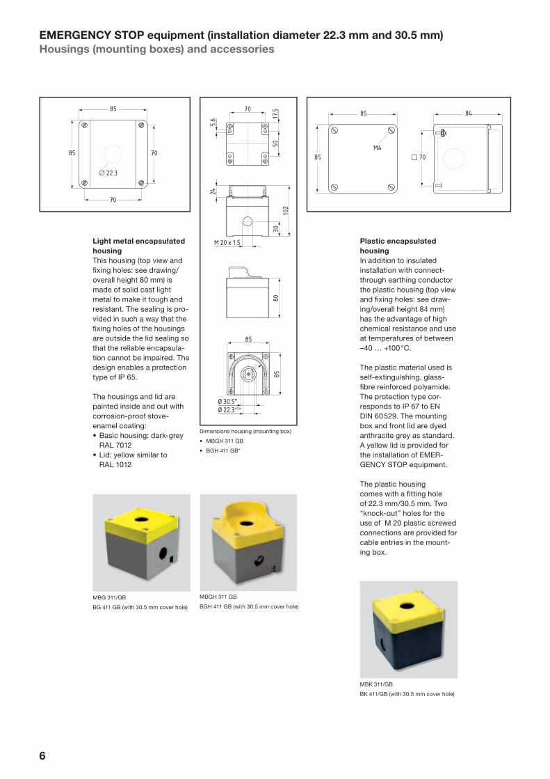
EMERGENCY STOP equipment (installation diameter 22.3 mm and 30.5 mm)
Housings (mounting boxes) and accessories
Plastic encapsulated
housing
In addition to insulated installation with connect-through earthing conductor the plastic housing (top view and fi xing holes: see draw-ing/overall height 84 mm) has the advantage of high chemical resistance and use at temperatures of between –40 … +100 °C.
The plastic material used is self-extinguishing, glass-fi bre reinforced polyamide. The protection type cor-responds to IP 67 to EN DIN 60 529. The mounting box and front lid are dyed anthracite grey as standard. A yellow lid is provided for the installation of EMER-GENCY STOP equipment.
The plastic housing comes with a fi tting hole of 22.3 mm/30.5 mm. Two “knock-out” holes for the use of M 20 plastic screwed connections are provided for cable entries in the mount-ing box.
Light metal encapsulated
housing
This housing (top view and fi xing holes: see drawing/overall height 80 mm) is made of solid cast light metal to make it tough and resistant. The sealing is pro-vided in such a way that the fi xing holes of the housings are outside the lid sealing so that the reliable encapsula-tion cannot be impaired. The design enables a protection type of IP 65.
The housings and lid are painted inside and out with corrosion-proof stove-enamel coating:• Basic housing: dark-grey
RAL 7012• Lid: yellow similar to
RAL 1012
MBK 311/GB
BK 411/GB (with 30.5 mm cover hole)
85
M5
∅ 22.3
85
70
70
MBG 311/GB
BG 411 GB (with 30.5 mm cover hole)
MBGH 311 GB
BGH 411 GB (with 30.5 mm cover hole)
Dimensions housing (mounting box)
• MBGH 311 GB
• BGH 411 GB*
85 84
M485 70
70
M 20 x 1.5
85
Ø 30.5*Ø 22.3+0.4
8530
5017
.5
245.
6
102
80

7
Product range
Brief description Version Type Catalogue
no.
Part no.
Plastic encapsulatedhousing
Empty housing with lid,bored
MBK 311/GB 066 0120 101 8717
Light metal encapsulatedhousing
Empty housing with lid,bored
MBG 311/GB 064 5214 100 8292
Protection collar– for actuators ∅ 38.5 mm for installation-∅ 22.3 mm
for installation-∅ 30.5 mmEDRR-1EDRR-1.1
071 3251071 3252
102 4268102 4270
– for actuators ∅ 49 mm for installation-∅ 22.3 mmfor installation-∅ 30.5 mm
EDRR-2EDRR-2.1
071 3253071 3254
102 4271102 4273
EMERGENCY STOP signs– for installation-∅ 22.3 mm 53 mm outer diameter
100 mm outer diameterMDP-8MDP-6
070 1939070 1921
100 1336100 9084
– for installation-∅ 30.5 mm 53 mm outer diameter100 mm outer diameter
DPF-9DPF-7
070 1912070 1904
100 0574100 0572
Adapter ring MUE 071 7908 101 7057
Adapter ring, type MUE
EMERGENCY STOP equipment
Housings (mounting boxes) and accessories
Protection collar against unintentional activation
Brief description:• Contrast colour yellow• Front panel depth max. 3 mm• Protective collar height 27.5 mm• Material: Al casting, powder-coated
EMERGENCY STOP signs
Brief description:• Painted yellow according
to RAL 1012• Without inscription• Material: Al powder-coated
Adapter ring with seal for
installation of 22 mm ac-
tuators in 30.5 mm hole
Brief description:• Aluminium anodized, with
seal and thrust washer• With use of the adapter
ring the maximum front panel depth is reduced to 4 mm.
Protective collar
• Left: EDRR-1 (for actuators ∅ 38.5 mm)
• Right: EDRR-2 (for actuators ∅ 49 mm)
EMERGENCY STOP signs MDP-6
(top) and DPF-9
8245
68
2.5 R
z 25
2
97.555
78
31
Ø 30.5Ø 22.5
2.5 R
z 25
2
31
Ø 30.5Ø 22.5

8
EMERGENCY STOP equipment EDRR../EDRZ..
Technical data
EMERGENCY STOP equipment
Regulations (if applicable) • IEC/EN 60 947-5-1• IEC/EN 60 947-5-5• IEC 60 947-1• EN ISO 13 850
Design round
Installation diameter 22.3 mm
Grid dimension • with head-∅ 40 mm: 50 × 40 mm• with head-∅ 50 mm: 50 × 50 mm
Front plate thickness 1 … 6 mm
Installation position any
Designation Identifi cation plates, symbols
Climatic resistance to DIN EN 60 068 Part 2-30
Ambient temperature – 25 °C … + 75 °C
Protection type to IEC 60 529 IP 65
Full insulation yes
Material mushroom-button Al anodized
Type of fi xing mounting fl ange
Max. torque for mounting screws ELM 0.6 Nm
Actuating force approx. 25 N
Mechanical life 1 × 10⁵ switching cycles
Rohs-conformity yes
Contact elements
Regulations IEC/EN 60 947-5-1
Rated operating voltage Ue max. 400 V
Rated insulation voltage Ui at pollution degree 3 to IEC 60 947-1
400 V
Rating of surge resistance voltage Uimp 4 kV
Thermal rated current Ith (in air) 10 A
Rated operating current Ie as dependent on the utilisationcategory and test voltage
• 8 A, AC-15, 250 VAC• 5 A, DC-13, 24 VDC
Low voltage capability 5 VDC/1 mA
Short-circuit protection gG 10 A
Proof of positive opening 2.5 kV impulse voltage
Positive opening path approx. 2 mm after achieving opening point
Air clearance and creepage distance to DIN EN 60 664-1 4 kV/3
Switching frequency 1,200 s/h
Switching points according to contact type
Temperature range – 25 °C … + 60 °C
Climatic resistance to DIN EN 60 068 part 2-30
Installation position random
Mechanical life 10 × 106 switching cycles
Actuating force at stroke end approx. 9 N
Terminal designations to IEC 60 947-1
Type of mounting • Screwed connection• Tab (fl at pin) connection• Cage-clamp connection• PCB connection
Mounting diameter • Single core: 2 × (0.5 … 2.5 mm2)• Dual core with wire-end ferrules: 2 × (0.5 … 1.5 mm2)
Tightening torque of the connection terminals max. 1 Nm
Shock protection present (to EN 50 274 and BGV A2)
Type of protection • Connections: IP 20 (fi nger-safe)• Switching elements: IP 40
Approvals cULus (except: Cage-clamp and PCB connection)

9
Control devices and indicator lamps (top parts) –
versions for rough industrial applicationsGeneral description
Concept
The development of this 22 mm range of control devices and indicator lamps represents a switch-ing device concept from Elan which offers the user improved performance, reliability and utilisation of space extending beyond the usual state-of-the-art. The EF/EL contact and light ter-minal block system makes a particular contribution in this respect. Proven conven-tional features of earlier Elan designs have been incorpo-rated in this improved type.
Control devices and
indicator-lamp actuators
A wide variety of totally insu-lated push-buttons, impact push-buttons, illuminated push-buttons, selector switches, momentary con-tact redary control switches etc. are offered in the 22 mm range. The front face of the actuators is made of anod-ized aluminium. The lens is made of glass. In addition to high mechanical resistance this choice of materials pro-vides above-average resis-tance to chemical reactions, such as from detergents, lubricants and coolants, and, in extreme cases, even brake fl uid and similar ag-gressive medium.
Protection type
The front sealing of the device conforms with protection type IP 67/65 in accordance with EN DIN 60 529.
The design features of the device sealing1 guarantee a high level of protection over a long period of time even under extreme operating conditions, e.g. against pen-etration by oil, organic and inorganic grease residues, grinding dust and the effects of high switching frequency.
System design
A control and indicator device consists of the sub-assemblies “actuator with mounting fl ange” and the “contact or light terminal block”. The type designation for this series (type) starts with E…, e.g. EDT for a push-button.
The EFM mounting fl ange is used for control devices and the ELM mounting fl ange for indicator lamps/pilot lights.
Single hole fi xing
The devices are designed for fi tting holes ∅ 22.3+0,4 mm. An additional lug cut-out to prevent rotation in the hole is not necessary for Elan devices.
Installation grid spacing
It is possible to fi t a number of switches with the follow-ing minimum intervals:
Min
imu
m d
ista
nc
e
be
twe
en
mo
un
tin
g
ho
les (
ho
le c
en
tre
to h
ole
ce
ntr
e)
DIN
EN
50 0
47
1
wit
h s
ing
le-h
an
d-
ed
mo
un
tin
g2
Horizontal 30 mm 40 mm
Vertical 50 mm 50 mm
Vertical 30 mm 40 mm
Horizontal 50 mm 50 mm
Fitting of devices
The actuator is accurately aligned and fi rmly pressed into the DIN fi tting hole. The retention lugs have a self-holding function so that the mounting fl ange can be pushed up at an angle from the rear of the front panel and then rotated into locked position and screwed tight. The actuator is to be inserted into the fi rmly held mounting fl ange and suit-ably positioned within the 30 × 50 mm installation grid spacing.
Please note:
You will achieve the best
possible fi tting for the
mounting fl ange if the two
screws are tightened more
or less evenly, but only
so far that the point of
screws touches the front
panel, i.e. avoid tightening
to the absolute limit (max.
0.6 Nm).
1 Exception: For technical reasons
the design dimensions of the ELT
and ELV light terminal blocks
require an installation grid spacing
of 40 × 50 mm. However, it is suf-
fi cient to leave the fi rst position on
the mounting fl ange unoccupied
in the next adjacent unit in order
to utilise this space for the extra
10 mm width.
2 See also “Fitting of devices”
3 The bellows seal shown in this
example of a push-button is
securely fi xed at its inner diameter
between the push-button and the
plunger and has its outer diameter
squeezed into the surround by
means of a threaded lock nut. This
ensures that both the position and
the functioning of the bellows seal
cannot be impaired even under
in-service stress.
4 Touch-predected to VDE 0106,
VBG 4 etc.
Push-button
Bezel
Front panel seal(standard: NBR;PTFE rings: page 40)
Retaining lugs
Threaded lock nut
Bellows seal
Plunger
All metal orwith glass lens
Front panel sealto IP 67/65
Self-lockingassembly retention lugs
90° centering of the actuators
Mounting flange forthree elements, eachwith two galvanicallyseparated contact circuits
High-grade stainlesssteel “snap-on” clips
Four-way contact bridgewith galvanically isolatedseparation
Optional tab (flat-pin)connection4 6.3 mm or2 x 2.8 mm
Slot for standardidentification plates
Optional screw-connection terminal 2 x 2.5 mm2

10
Control devices and indicator lamps (top parts) –
versions for rough industrial applicationsProduct range
Push-buttons and push-buttons with diaphragm
Brief description Function Colour Type Catalogue
no.
Part no.
Push-button blackyellowredgreenwhiteblue
EDT swEDT gbEDT rtEDT gnEDT wsEDT bl
027 0010027 0015027 0020027 0025027 0030027 0035
100 6229100 6231100 6233100 6235100 6237100 6239
Push-button with 2 mm pro-truding button
Provides “visible” and “tangible” distinction where several OFF buttons are mounted on one panel.
blackyellowredgreenwhiteblue
EDT2 swEDT2 gbEDT2 rtEDT2 gnEDT2 wsEDT2 bl
027 0110027 0115027 0120027 0125027 0130027 0135
100 6245100 6246100 6248100 6250100 6252100 6254
Push-button with 6 mm pro-truding button
Preferable for use as OFF switch. Switches off imme-diately the button is pressed by the palm of the hand.
blackyellowredgreenwhiteblue
EDT6 swEDT6 gbEDT6 rtEDT6 gnEDT6 wsEDT6 bl
027 0210027 0215027 0220027 0225027 0230027 0235
100 6255100 6256100 6257100 6258100 6259100 6260
Push-button with protruding rim (approx. 6 mm)
Provides increased protection from unintentional actuation.
blackyellowredgreenwhiteblue
EDTH swEDTH gbEDTH rtEDTH gnEDTH wsEDTH bl
027 0310027 0315027 0320027 0325027 0330027 0335
100 6242100 6263100 6264100 6265100 6266100 6267
Push-button with diaphragm
The diaphragm protects the button from grinding dust or other pasty, viscous medium. Symbols still easily legible.
blackyellowredgreenwhiteblue
EDM swEDM gbEDM rtEDM gnEDM wsEDM bl
027 0410027 0415027 0420027 0425027 0430027 0435
100 6268100 6269100 6270100 6271100 6272100 6273
Push-button with diaphragm and protruding rim (approx. 6 mm)
The diaphragm protects the button from grinding dust or other pasty, viscous medium. Rim protects against uninten-tional actuation. Symbols still easily legible.
blackyellowredgreenwhiteblue
EDMH swEDMH gbEDMH rtEDMH gnEDMH wsEDMH bl
027 0510027 0515027 0520027 0525027 0530027 0535
100 6274100 6275100 6276100 6278100 6279100 6280
Push-button with latching(push-button switch)
blackyellowredgreenwhiteblue
EDTR sw*EDTR gb*EDTR rt*EDTR gn*EDTR ws*EDTR bl*
027 1810027 1815027 1820027 1825027 1830027 1835
100 6357118 7390100 6359100 6360100 6361100 6362
Diaphragm as spare part DL 30 071 2595 100 0545
Mounting fl ange EFM supplied.
* Only in connection with contact element EF 102.
22
14
29.5
Dimensions of basic device EDT ..
Mounting fl ange EFM supplied.
EDT ..
EDT6 ..
EDTH ..
EDT2 ..
11
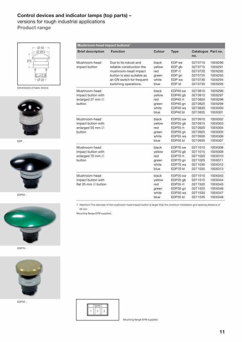
Control devices and indicator lamps (top parts) –
versions for rough industrial applicationsProduct range
Mushroom-head impact buttons1
Brief description Function Colour Type Catalogue
no.
Part no.
Mushroom-head impact button
Due to its robust and reliable construction the mushroom-head impact button is also suitable as an ON switch for frequent switching operations.
blackyellowredgreenwhiteblue
EDP swEDP gbEDP rtEDP gnEDP wsEDP bl
027 0710027 0715027 0720027 0725027 0730027 0735
100 6290100 6291100 6292100 6293100 6294100 6295
Mushroom-head impact button with enlarged 37 mm ∅ button
blackyellowredgreenwhiteblue
EDP40 swEDP40 gbEDP40 rtEDP40 gnEDP40 wsEDP40 bl
027 0810027 0815027 0820027 0825027 0830027 0835
100 6296100 6297100 6298100 6299100 6300100 6301
Mushroom-head impact button with enlarged 55 mm ∅ button
blackyellowredgreenwhiteblue
EDP55 swEDP55 gbEDP55 rtEDP55 gnEDP55 wsEDP55 bl
027 0910027 0915027 0920027 0925027 0930027 0935
100 6302100 6303100 6304100 6305100 6306100 6307
Mushroom-head impact button with enlarged 70 mm ∅ button
blackyellowredgreenwhiteblue
EDP70 swEDP70 gbEDP70 rtEDP70 gnEDP70 wsEDP70 bl
027 1010027 1015027 1020027 1025027 1030027 1035
100 6308100 6309100 6310100 6311100 6312100 6313
Mushroom-headimpact button with fl at 35 mm ∅ button
blackyellowredgreenwhiteblue
EDP35 swEDP35 gbEDP35 rtEDP35 gnEDP35 wsEDP35 bl
027 1510027 1515027 1520027 1525027 1530027 1535
100 6343100 6344100 6345100 6346100 6347100 6348
1 Attention! The diameter of the mushroom-head impact button is larger than the minimum installation grid spacing distance of
30 mm.
Mounting fl ange EFM supplied.
22
27.5
29.532
Dimensions of basic device
Mounting fl ange EFM supplied.
EDP55 ..
EDP ..
EDP70 ..
EDP35 ..

12
Control devices and indicator lamps (top parts) –
versions for rough industrial applicationsProduct range
Mushroom-head impact button with latching1, 2, 3
Brief description Function Colour Type Catalogue
no.
Part no.
Mushroom-head impact button with latching and enlarged 70 mm ∅ button
Released by turning the button in direction of arrow.
blackyellowredgreenwhiteblue
EDR70 swEDR70 gbEDR70 rtEDR70 gnEDR70 wsEDR70 bl
027 1410027 1415027 1420027 1425027 1430027 1435
100 6336100 6337100 6338100 6340100 6341100 6342
Mushroom-head impact button with latching, 38.5 mm ∅ button
Released by turning the button in direction of arrow.
blackyellowredgreenwhiteblue
EDR40 swEDR40 gbEDR40 rtEDR40 gnEDR40 wsEDR40 bl
027 1210027 1215027 1220027 1225027 1230027 1235
100 6320100 6321100 6322100 6324100 6325100 6326
Mushroom-head impact button with latching and lock for unlocking, 38 mm ∅, key no. 4A/85
The key entry is covered by an aluminium cover in anodised red.
red EDRS40 rt 027 1720 100 6356
Mushroom-head impact button with latching and fl at 35 mm ∅ button
Released by turning the button in clockwise direction.
blackyellowredgreenwhiteblue
EDR35 swEDR35 gbEDR35 rtEDR35 gnEDR35 wsEDR35 bl
027 1610027 1615027 1620027 1625027 1630027 1635
100 6349100 6350100 6351100 6353100 6354100 6355
1 Attention! The diameter of the mushroom-head impact button is larger than the minimum installation grid spacing distance of
30 mm.
2 EMERGENCY STOP equipment: see pages 2–8
3 Mushroom-head impact button with latching of this type cannot be combined with EFR spring elements.
Mounting fl ange EFM supplied.
Mounting fl ange EFM supplied.
EDR70 ..
EDR40 ..
EDRS40 rt
EDR35 ..

13
Control devices and indicator lamps (top parts) –
versions for rough industrial applicationsProduct range
Maintained spring-return rotary selector switches, selector switches
Brief description/
function1
Type3 Catalogue
no.
Part no.
Spring-return rotary selector switch with 1 touch position and automatic return to zero position
EWT21EWT21.1
027 2000027 2010
100 6369100 6370
Spring-return rotary selector switch with 1 touch position2 to the right and left of the zero position
EWT32EWT32.1
027 2020027 2030
100 6371100 6372
Maintained spring-return rotary selector switch with 1 touch position to the right and two latched positions2
EWTS32EWTS32.1
027 2035027 2040
100 6373100 6374
Maintained spring-return rotary selector switch with 1 touch position to the left and two latched positions2
EWTS321EWTS321.1
027 2045027 2050
100 6375100 6376
Selector switch with 2 latched positions
EWS21EWS21.1
027 2060027 2070
100 6377100 6378
Selector switch with 2 latched positions2
EWS32EWS32.1
027 2080027 2090
100 6379100 6380
1 Contacts: 1 NC/1 NO. Further switching functions can be achieved by using other contact complements (refer to pages 34 et seq.).
2 Zero position monitoring with additional contact block to position 3 on the mounting fl ange.
3 Suffi x .1 = 46 mm long grip.
Mounting fl ange EFM supplied.
Dimensions of basic device
0
0
35° 35°I II
III
55°
0 I
0 I
0
0
55° 35°
I
II
III
0
0
35° 55°I II
III
70°
0
0
I
I
0
0
55° 55°
III
III
Mounting fl ange EFM supplied.
EWT.../EWS...
EWT... .1/EWS... .1

14
Control devices and indicator lamps (top parts) –
versions for rough industrial applicationsProduct range
Key-operated selector switches1/Key-operated maintained spring-return selector switches1
Brief description/function2 Key with-
drawal
position
Type Catalogue
no.
Part no.
Key-operated selector switch with 2 latched positions
0I0 + I
ESS21S1ESS21S2ESS21S12
027 2170027 2180027 2190
100 6385100 6386100 6387
Key-operated selector switch with 3 latched positions3
I0III + 0 + II
ESS32S14
ESS32S24
ESS32S3ESS32S123
027 2200027 2210027 2220027 2230
100 6390100 6391100 6392100 6393
Key-operated maintained spring-return selector switch with 1 touch position and automatic return to the zero position
0 EST21S1 027 2100 100 6382
Key-operated maintained spring-return selector switch with 2 touch positions3 and automatic return to the zero position
0 EST32S2 027 2140 100 6384
Key-operated selector switch/key-operated maintained spring-return selector switch with 3 positions
Touch position35° switching anglerightrightleftleft(zero position centre, key entry top)
Latch position55° switching angleleftleftrightright
I00II
ESTS32S1ESTS32S2ESTS321S2ESTS321S3
027 2240027 2250027 2260027 2270
100 6396100 6397100 6398100 6399
Spare key EKM 30 for CES lock; special locks: on request
SDS2 072 1191 100 1629
1 Protection type: IP 65/CES lock, closure EKM30 (standard).
2 Contacts: 1 NC/1 NO. Further switching functions can be achieved by using other contact complements (refer to pages 34 et seq.)
3 Zero position monitoring with additional contact block to position 3 on the mounting fl ange.
4 Switching angle 2 × 55°.
Mounting fl ange EFM supplied.
22
27
33
29.522
Dimensions of basic device0
0
I II
III
90° 90°
90°
0 I
0 I
55°0 I
0 I
0
0
35°35°III
III
Mounting fl ange EFM supplied.
ESS.../EST...

15
Control devices and indicator lamps (top parts) –
versions for rough industrial applicationsProduct range
Key-operated switches
Brief description Function Key with-
drawal
position
Type Catalogue
no.
Part no.
Key-operated switches
The key switch head has an internal secured bellows seal. Protection type: IP 65. Standard lock: 13220Special locks available on request.
1011121314151617
EDS10EDS11EDS12EDS13EDS14EDS15EDS16EDS17
027 0610027 0615027 0620027 0625027 0630027 0635027 0640027 0645
100 6281100 6282100 6284100 6284100 6285100 6286100 6287100 6289
Spare key SDS1 072 1166 100 0662
Versions of the key-operated switches
Key withdrawal position
Push-button function in zero position
Key with-drawable in zero position
Lockable in zero position
Key with-drawable in locked position
Switch function
actuator hand-held
latched position/lockable
latched position/key with-drawable
10 • • • • – • •
11 • • • • • – –
12 • • – – – • •
13 – – • • – • •
14 – – • • • – –
15 – – – – – • •
16 – – • • – • –
17 – – – • – • •
Zero position = button not depressed, key entry at bottom.
Mounting fl ange EFM supplied.
22
31
29.5
29.5
Mounting fl ange EFM supplied.
Dimensions of basic device
EDS..

16
Control devices and indicator lamps (top parts) –
versions for rough industrial applicationsProduct range
Illuminated push-buttons and illuminated push-buttons with diaphragm
Brief description Function Colour Type Catalogue
no.
Part no.
Illuminated push-button yellowredgreenwhiteblue
EDL gbEDL rtEDL gnEDL wsEDL bl
027 5015027 5020027 5025027 5030027 5035
100 6400100 6402100 6404100 6406100 6408
Illuminated push-button with diaphragm
Symbols still easily legible under the trans-parent diaphragm.
yellowredgreenwhiteblue
EDLM gbEDLM rtEDLM gnEDLM wsEDLM bl
027 5215027 5220027 5225027 5230027 5235
100 6420100 6421100 6422100 6423100 6424
Illuminated push-button with protruding rim (approx. 6 mm)
The protruding rim offers increased pro-tection from uninten-tional actuation.
yellowredgreenwhiteblue
EDLH gbEDLH rtEDLH gnEDLH wsEDLH bl
027 5415027 5420027 5425027 5430027 5435
100 6430100 6431100 6432100 6443100 6434
Illuminated push-buttonwith diaphragm and protruding rim(approx. 6 mm)
The protruding rim offers increased pro-tection from uninten-tional actuation.
yellowredgreenwhiteblue
EDLMH gbEDLMH rtEDLMH gnEDLMH wsEDLMH bl
027 5615027 5620027 5625027 5630027 5635
100 6440100 6441100 6442100 6443100 6444
Illuminated push-button with latching (illuminated push-button switch)
yellowredgreenwhiteblue
EDLR gb*EDLR rt*EDLR gn*EDLR ws*EDLR bl*
027 5815027 5820027 5825027 5830027 5835
100 6450100 6451100 6452100 6453100 6454
Diaphragm as spare part EDL-5 071 2599 115 8180
Mounting fl ange ELM supplied.
* Only in connection with contact element EF 102.
22
14
29.516
Dimensions of basic device
Mounting fl ange ELM supplied.
EDL ../EDLR ..
EDLM ..
EDLMH ..

17
Control devices and indicator lamps (top parts) –
versions for rough industrial applicationsProduct range
Pilot lights
Brief description Function Colour Type Catalogue
no.
Part no.
Pilot lights with fl at glass yellowredgreenwhiteblue
EML gbEML rtEML gnEML wsEML bl
027 6015027 6020027 6025027 6030027 6035
100 6460100 6461100 6462100 6463100 6465
Pilot lights with pro truding glass (approx. 6 mm)
Visible from all angles(symbols not possible).
yellowredgreenwhiteblue
EMLH gbEMLH rtEMLH gnEMLH wsEMLH bl
027 6115027 6120027 6125027 6130027 6135
100 6466100 6467100 6468100 6469100 6470
Mounting fl ange ELM supplied.
22
14
29.5
Montagefl ansch ELM supplied for pilot lights.
Dimensions of basic device EML ../
EMLH ...
Dimensions of basic device EKS
EML ..
EMLH ..
EKS
Toggle switch
Brief description Type Catalogue
no.
Part no.
Toggle switch EKS 027 2095 100 6381
Mounting fl ange EFM supplied.
Mounting fl ange EFM supplied for toggle switch.

18
LED indicator lights/illuminated push-buttons
General description
Application
The illuminated push-buttons and indicator lights of this range work with integrated LEDs. This design version combines the feature of virtually unlimited service-able life as provided by the LED modules, with the advantage of a brightness and illumination which is comparable to devices with incandescent bulbs.
The high availability or useful life of the LED devices thus cuts out the necessity to change bulbs in the con-ventional manner. There are no direct or indirect conse-quential expenses from bulb failure. The expenditure for bulb test circuits can simi-larly be reduced.
A further advantage of the devices is the current input without inrush peak. This means that special bulb-proof in- and outputs are not required in electronic control circuitry.
The LED indicator lights and illuminated push-buttons were developed for applica-tions with a high ON period in highly diversifi ed plants and for displays which are particularly important.
The devices for industrial use come in tough design and are dust- and watertight encapsulated. In order to facilitate extensively smooth adaptation to existing op-erating and control panels, the devices are offered in a variety of versions. The available colours are red, green and yellow.
Design
An LED indicator light con-sists of the modules “actua-tor with mounting fl ange”, either with metal or plastic bezel, and “light terminal block”. The actuators have a large super-bright multi-LED and are fully cast. The ball-shaped lens of the multi-LED also facilitates a good view from all angles.
The circuitry of the indica-tor lights is standard for 24 V universal current. The connection is made via a light terminal block with EL screw connection which is snapped on to the centre position of the mounting fl ange. There is a plug-in connection between actuator and block. The connections of the terminal block are protected against reverse voltage. However, X1 as plus pole is recommend-ed for reasons of uniform wiring.
Multi-LED+ –

19
LED pilot lights
Operating voltage Colour Installation-∅ 22.3 mm Installation-∅ 30.5 mm
Metal bezel Catalogue
no.
Order
no.
Metal bezel Catalogue
no.
Order
no.
24 V universal current
redgreenyellow
EME RT/ELEEME GN/ELEEME GB/ELE
027 7035027 7037027 7039
100 6511100 6513100 6515
EME RT V/ELEEME GN V/ELEEME GB V/ELE
027 7000027 7062027 7064
100 6520100 6522100 6524
36 … 60 V universal current
redgreenyellow
EME RT/ELE 48EME GN/ELE 48EME GB/ELE 48
027 7052027 7053027 7054
120 4494120 4495120 4496
EME RT V/ELE 48EME GN V/ELE 48EME GB V/ELE 48
027 7078027 7079027 7080
120 4497120 4498120 4499
110 … 230 VAC redgreenyellow
EME RT/ELE 230EME GN/ELE 230EME GB/ELE 230
027 7047027 7049027 7051
100 6517100 6518100 6519
EME RT V/ELE 230EME GN V/ELE 230EME GB V/ELE 230
027 7072027 7074027 7076
100 6526100 6527100 6528
Flash circuitry 24 VDC(230 V ~-version: on request)
redgreenyellow
EME RT/ELEBEME GN/ELEBEME GB/ELEB
027 6565027 6570027 6560
100 6490100 6491100 6519
EME RT V/ELEBEME GN V/ELEBEME GB V/ELEB
027 7060027 7074027 7076
100 6520100 6527100 6528
LED pilot lights
with metal and plastic bezel
Higher voltages/fl ash circuitry
Higher voltages (36 … 60 V universal cur-rent/110 … 255 VAC) can be provided via light terminal blocks with appropriate addi-tional circuitry. An additional module is also provided for the 24 V∼ fl ash circuitry.
29.5
46
a
b
60
Dimensions 24 V universal current,
metal bezel, installation-∅ 22.3 mm;
a) actuator with mounting fl ange;
b) light terminal block
35.520
1,5
… 6
46
a
b
71
12
Dimensions 24 V universal current,
metal bezel, installation-∅ 30.5 mm;
a) actuator with mounting fl ange;
b) light terminal block
29.5
30
56

20
LED illuminated push-buttons
with metal and plastic bezel
LED illuminated push-but-tons consist of the sub-assemblies “actuator with mounting fl ange” and “LED light terminal block”.
A multi-LED (8×) with 9 mm ∅ illuminated area is inte-grated into the light terminal block.
By comparison with base LEDs, this component is placed on a spade to provide a higher illuminated level and thus improved illumination. The standard range is 24 VDC (other oper-ating voltages: on request).
The LED light terminal block with screw connection is snapped on to the centre position of the mounting fl ange. The non-occupied positions 1 and 3 are avail-able to snap on the requisite contact blocks.
The illuminated push-button actuators are available either with metal bezel and plastic lens or all plastic. The metal bezel version is the version EDLE.
LED
X2 X1
LED illuminated push-buttons
Description Colour Installation-∅ 22.3 mm Installation-∅ 30.5 mm
Metal bezel Catalogue
no.
Order
no.
Metal bezel Catalogue
no.
Order no.
Illuminated push-button (actuator with mounting fl ange)
redgreenyellowwhiteblue
EDLE RTEDLE GNEDLE GBEDLE WSEDLE BL
027 6750027 6755027 6760027 6740027 6745
100 6492100 6493100 6494117 0533102 9320
EDLE RT VEDLE GN VEDLE GB VEDLE WS VEDLE BL V
027 6780027 6785027 6790027 6796027 6797
100 6498100 6499100 6500120 4487120 4488
Illuminated push-button switch1 (actuator with mounting fl ange)
redgreenyellowwhiteblue
EDLER RTEDLER GNEDLER GBEDLER WSEDLER BL
027 6765027 6770027 6775027 6776027 6777
100 6495100 6496100 6497120 4492120 4493
EDLER RT VEDLER GN VEDLER GB VEDLER WS VEDLER BL V
027 6795027 6800027 6805027 6810027 6815
100 6501100 6502100 6503120 4489120 4490
1 By contrast to the illuminated push-button (momentary contact switch), the illuminated push-button switch is a maintained contact switch with two pronounced
switch positions. Upon fi rst actuation the switch remains locked into the ON latched position – the button remains visibly depressed – until such times as the ON
position is returned to the original setting by renewed depression.
LED light terminal blocks
Description Colour Type Catalogue no. Order no.
24 V universal current, screw connection redgreenyellowbluewhite
ELDE.N RT 24ELDE.N GN 24ELDE.N GB 24ELDE.N BL 24ELDE.N WS 24
027 6610027 6612027 6611027 6613027 6614
116 5995116 5997116 5998116 5999116 6000
48 VDC/AC redgreenyellowbluewhite
ELDE.N RT 48ELDE.N GN 48ELDE.N GB 48ELDE.N BL 48ELDE.N WS 48
027 6615027 6617027 6616027 6618027 6619
116 7521116 7523116 7522116 7524116 7525
230 VAC, screw connection redgreenyellowbluewhite
ELDE.N RT 230ELDE.N GN 230ELDE.N GB 230ELDE.N BL 230ELDE.N WS 230
027 6625027 6627027 6626027 6628027 6629
116 6022116 6023116 6024116 6025116 6026

21
LED illuminated push-buttons
with metal and plastic bezel
max
. 6
46
b
c
60
a
29.522
Installation-∅ 22.3 mm, metal bezel;
a) illuminated push-button actuator, b) mounting fl ange,
c) light terminal block
14
10a
10b
10c
d
52
29.522
Installation-∅ 22.3 mm, metal bezel;
a) + c) contact terminal blocks, b) light terminal block,
d) screw connection
Dimensions of the complete devices
46
b
c
a
34.5+0.2
2.530.5
Installation-∅ 30.5 mm, metal bezel
Light terminal block with integrated Multi-LED with WAGO cage clamp system
Schaltbild Colour Type Catalogue no. Order no.
24 VDC/AC
rotgelbgrünblauweiß
ELDEK RTELDEK GBELDEK GNELDEK BLELDEK WS
027 6650027 6651027 6652027 6653027 6654
116 7381116 7382116 7383116 7384116 7385

22
LED devices
Protection type of actuators IP 67 (1 m WS/30 min.)
Current input 24 VDC • LED indicator light 40 mA• LED illuminated push-button max. 20 mA
Power consumption 24 V • LED indicator light 1 W• LED illuminated push-button max. 0.45 W
Temperature ranges – 25 °C … + 40 °C
ON period 100%
Screw connections 2 × 0.5 … 2.5 mm2 or 1.5 mm2 with wire-end ferrule
Device assembly (grid spacing in accordance with DIN 50 007)
The actuator is accurately aligned and fi rmed plugged into the DIN fi tting hole. The retention lugs provide a self-holding func-tion so that the mounting fl ange can be pushed up at an angle from the rear front panel and then rotated into lock position and screwed tight.
LED devices
Technical data
Control elements
Regulations • IEC/EN 60 947-5-1• IEC 60 947-1
Design round
Installation diameter 22.3 mm
Grid dimension • 40 × 50 mm• 50 × 60 mm (selector switches, mushroom-head impact
buttons with latching)
Front plate thickness 1 … 6 mm
Installation position random
Designation Identifi cation plates, symbols
Climatic resistance to DIN EN 60 068 part 2-30
Ambient operating temperature • Push-button: – 25 °C … + 75 °C• Illuminated push-button with LED (by Elan): – 25 °C … + 75 °C• Pilot light mit bulb: – 25 °C … + 40 °C• Pilot light with LED (by Elan): – 25 °C … + 75 °C• Impact button: – 25 °C … + 75 °C• Selector switch/
rotary drive for potentiometer: 0 °C … + 75 °C• Key-operated switch: 0 °C … + 75 °C
Switching frequency 1,000 s/h
Protection type to IEC 60 529 IP 65
Full insulation yes
Materials • Swivel: glas• Swivel (plastics): PC• Frontring/buttons: Al anodized
Type of fi xing with mounting fl ange
Max. torque for mounting screws EFM/ELM 0.6 Nm
Shock resistance to IEC 60 068-2-27 • Device without bulb: < 50 g• Device with bulb: < 30 g
Vibration resistance to IEC 60 068-2-6 5 g
Actuating stroke 4 mm
Actuating force • Push-button: approx. 1.5 N• Push-button with diaphragm: approx. 2 N• Pilot light: approx. 1.5 N• Key-operated switch: approx. 0.2 Nm• Selector switch: approx. 0.2 Nm• Impact button: approx. 2 N
Mechanical life • Push-button: 10 × 106 switching cycles• Illuminated push-button: 5 × 10⁶ switching cycles• Selector switch: 3 × 10⁵ switching cycles
Rohs-conformity yes
23
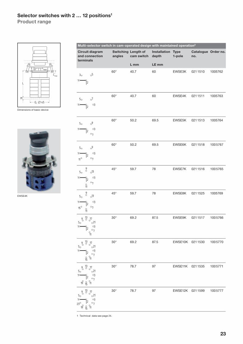
Selector switches with 2 … 12 positions1
Product range
Multi-selector switch in cam-operated design with maintained operation2
Circuit diagram
and connection
terminals
Switching
angles
Length of
cam switch
L mm
Installation
depth
LE mm
Type
1-pole
Catalogue
no.
Order no.
60° 40.7 60 EWSE3K 021 1510 1005762
60° 40.7 60 EWSE4K 021 1511 1005763
60° 50.2 69.5 EWSE5K 021 1513 1005764
60° 50.2 69.5 EWSE6K 021 1518 100 5767
45° 59.7 78 EWSE7K 021 1516 100 5765
45° 59.7 78 EWSE8K 021 1525 1005769
30° 69.2 87.5 EWSE9K 021 1517 100 5766
30° 69.2 87.5 EWSE10K 021 1530 100 5770
30° 78.7 97 EWSE11K 021 1535 100 5771
30° 78.7 97 EWSE12K 021 1599 100 5777
1 Technical data see page 24.
Dimensions of basic device
EWSE4K

24
Selector switches with 2 … 12 positions
Protection type IP 65
Grid spacing 50 × 60 mm
Continuous current Ith 12 A
Rated operating voltage 660 V
Rated operating current AC1 16 A/440 V14 A/660 V
Terminal cross section 0.5 … 2.5 mm2 rigid0.5 … 1.5 mm2 fl exible with wire-end ferrules
Touch protection in accordance with VDE 106, VBG 4
Mechanical serviceable life in accordance with DIN VDE 0660 part 200
1 Mio. switching cycles
Impact resistance > 25 g/11 ms
Full insulation voltage at 12 V too Ohmical load – (20 A)
In the case of switches with fl at pin connection the dimensions of the switching element change (quadratically).
Selector switches with 2 … 12 positions
Technical data
Dimension table
Number
of steps
Installed
depth L
2 69.5 mm
3 60.0 mm
4 60.0 mm
5 69.5 mm
6 69.5 mm
7 78.0 mm
8 78.0 mm
9 87.5 mm
10 87.5 mm
11 97.0 mm
12 97.0 mm
Step switch EWSE..
Device heads See page 23
Dimensions device heads see above
Cam switches Make: Kraus & Naimer, type series CA10
per step 1 NO contact (2-step switch, 3-pole)
Regulations to IEC 60 947-3 (VDE 0660 part 107)
Insulation voltage Ui 690 V
Thermal rated current 20 A
Power AC-23: 7.5 AAC-3: 5.5 A
Shock hazard protection EN DIN 50 274 (VDE 0660 part 514)
Corrosion protectionof the electrical parts
Corrosion protection for the electrical elements behind the front plate cannot be guaranteed.

25
Rotary drives for potentiometers
Product range
Rotary drives for potentiometers
Brief description/function Shaft length Type Catalogue
no.
Order no.
for 6 mm shaft diameter
The rotary drive has the same external form as the selector switch head and therefore matches the entire push-button range.
The potentiometers are to be procured from the manufacturers. A central hole fi tting facility and two different three-hole fi tting facilities are provided for mounting.
Protection type: IP 65
30 … 40 mm EDAN 6 052 2201 101 9612
45
6
63
55
max.33
max.58
38 width
Dimensions of basic device
EDAN 6
26
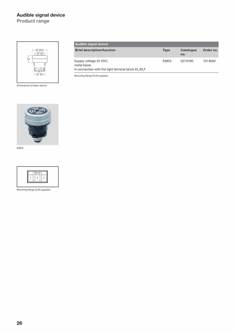
Audible signal device
Product range
Audible signal device
Brief description/function Type Catalogue
no.
Order no.
Supply voltage 24 VDC,metal bezel,in connection with the light terminal block EL/ELF
EMES 027 6190 101 8062
Mounting fl ange ELM supplied.22
14
29.522
Dimensions of basic device
Mounting fl ange ELM supplied.
EMES

27
Control devices and indicator lamps (top parts) –
Versions for clip-in symbols
Design features
These device versions for clip-in symbol plates are particularly suitable for all applications in mechani-cal and control engineer-ing where a broad variety of symbols and function designations are necessary. They make work easier and save on separate identifi -cation plates, front panel engravings etc. Another important advantage is the possible saving of space on the operating panel or on the control panel since control and indicator devices can be installed within a small installation grid. Another good idea is that the symbol plates can be clipped in after device assembly.
The possibility of describing device functions through clip-in symbols is not only provided for push-buttons, indicator lamps and similar devices, but also for selector switches and selector push-buttons or potentiometer rotary drives.
Thanks to their metal bezel the devices provide a high degree of toughness for industrial use of Control devices and indicator lamps. The symbol plates have miniaturized lugs for the ac-curate and tight clipping-in to the actuators. The symbol plates are made of glass fi bre reinforced industrial plastic. The symbols are printed using an industrial two-component dye.
Product range
Brief description Colour Type Cata-
logue no.
Order no.
Symbol plate1 fl at2, diameter 19 mm,polyamide red
bluegreenyellowwhiteblack
For illuminat-ed devices
E-KB9 RTE-KB9 BLE-KB9 GNE-KB9 GBE-KB9 WS–
For non-illumi-nated devices
E-KB9.1 RTE-KB9.1 BLE-KB9.1 GNE-KB9.1 GBE-KB9.1 WSE-KB9.1 SW
⎫⎪⎪⎪⎬⎪⎪⎪⎭
on request
Push-button standardditto with protruding ring
EDT KBEDTH KB
027 0005027 0305
101 7991101 7992
Selector switch – 2 positionsditto 3 positions
EWT 21.1 KBEWT 32.1 KB
027 2005027 2032
101 7995102 0705
Selector switch – 2 positionsditto 3 positions
EWS 21.1 KBEWS 32.1 KB
027 2065027 2092
101 7994102 0706
Selector push-button switch – 3 positions, 1 touch position to the left,2 latch positions to the right
EWTS 32.1 KB 027 2042 102 5981
Illuminated push-button, standard
EDL KB 027 5031 102 2456
Indicator lamp, standard EML KB BLEML KB RTEML KB GNEML KB WSEML KB GB
027 6040027 6045027 6050027 6055027 6060
120 4264101 8758101 8759101 8752101 8761
ditto with protruding ring EMLH KB BLEMLH KB RTEMLH KB GNEMLH KB WSEMLH KB GB
027 6100027 6103027 6106027 6109027 6112
101 8765101 8763101 8764101 8762101 8766
Push-buttons and illuminated push-buttons: on request
1 Optionally blank or with symbol (please specify: see page 52).
2 Raised versions: on request.
Mounting fl ange EFM or ELM supplied.

28
Control devices and indicator lamps (top parts) –
Versions for clip-in symbolsInstallation drawings
Push-button EDT KB
48
1922
1–1
max. 6
EDT KB
Contact element EF...,version as ordered
60
29.5
10 10
52
10
Push-button EDTH KB
max. 6
EDTH KB1922
22
16 19
1–0,1
Selector switch/selector push-button EWS/EWT... KB
max. 6
EWS.KBEWT.KB
1425
2613
1–0,1 40.5
1929.5
Illuminated push-button/indicator lamp EDL/EML... KB
EDL KBmax. 6
19 29.5
1 2 3
Inscription examples
EWT/EWS ... KB
EDT KB
EDL KB
EML KB ..
EMLH KB ..

29
Vandal-proof devices – installation-Ø 30.5 mmDesign features
Concept
Control devices and indica-tor lamps of the Elan D-30 V range with a mounting hole of 30.5 mm are character-ised by a particularly fl at front design. This design feature is achieved by a spe-cial bezel design combined with an additional spacer ring. A variety of fully insu-lated push-buttons, impact buttons, illuminated buttons, selector switches, momen-tary contact rotary control switches are offered in the D-30 V range.
One of the advantages of the fl at design is, for example, the facility to letter around the devices (see drawing left).
“Vandal-proof”
The device variations “push-button”, “illuminated push-button” and “pilot light” have a height of only 2.5 mm thus providing increased protec-tion against wilful destruc-tive impacts and tampering as, for example, can occur in public buildings, facilities, lifts etc.
The front of the actuators is made of anodised alu-minium. Lenses are made of thick glass.
In addition to a high me-chanical resistance, this choice of material also provides an above-average degree of resistance to chemical action such as from detergents, lubricants and coolants and in extreme cases even break fl uids and similar aggressive medium.
Protection type
The sealing of the devices from the front side of the panel conforms to protection type IP 67/65 in accordance with EN DIN 60 529. The bel-lows seal is securely fi xed at its inner diameter between the push-button and plunger and has its outer diameter squeezed into the surround by means of a threaded lock nut. This ensures that both the position and the func-tioning of the bellows seal cannot be improved even under in-service stress.
Changing bulbs
In order to achieve the fl at design of this range, also for pilot lights and illumi-nated push-buttons, and to prevent external tamper-ing, the bulbs are changed from the rear of the front panel. It should be remem-bered that in the case of illuminated push-buttons the contact blocks must fi rst be snapped off before disman-tling the light terminal blocks (symbols not possible).
Device installation
Control devices and indica-tor lamps in the D-30 V range consist of actuator with seal, a spacer ring and a mounting fl ange to be snapped on the contact and light terminal blocks. After insertion of the actuator into the installation hole of 30.5 mm (a lug cut-out to prevent rotation in the hole is not necessary for Elan devices) the spacer ring is guided from the rear side of the front panel over the actuator and the device then fi xed by means of the mounting fl ange. The fl ange comes in bayonet design. The best possible fi tting will be achieved if the two screws are tightened more or less evenly, but only so far that the point of the screws touches the front panel. The corresponding contact and light terminal blocks can then be snapped on.
Installation grid spacing
It is possible to fi t a number of switches with the follow-ing minimum intervals:
Dis
tan
ce
be
-
twe
en
mo
un
tin
g
ho
les (
ho
le c
en
tre
to h
ole
ce
ntr
e)
DIN
EN
50 0
47
1
Min
imu
m s
pa
cin
g
Horizontal 30 mm 40 mm
Vertical 65 mm 50 mm
Vertical 50 mm 40 mm
Horizontal 65 mm 50 mm
1 Touch-protected to VDE 0106,
VBG 4 etc.
All metal or with glass lens
Front panel seal to IP 65/67
Space ring
90° centering of the actuators
Mounting flange forthree elements, each withtwo galvanically separatedcontact circuits
High-grade steel“snap-on” clips
Four-way contact bridgewith galvanicallyisolated separation
Optionally tab (flat-pin)connection4 6.3 mm or2 x 2.8 mm
Nut für handelsüblicheBezeichnungsschilder
Optional screw-connection terminal 2 x 0.5 … 2.5 mm2
Vorschub
13 letters
13 letters

30
Vandal-proof devices1 – installation-Ø 30.5 mmProduct range
Push-button2
Brief
description
Function Colour Type Catalogue
no.
Order no.
Push-button, fl at blackyellowredgreenwhiteblue
EDT.V swEDT.V gbEDT.V rtEDT.V gnEDT.V wsEDT.V bl
026 6010026 6015026 6020026 6025026 6030026 6035
100 6143100 6144100 6145100 6146100 6147100 6148
Push-button with 2 mm pro-truding button
Provides visible and tangible distinction where several OFF switches are mounted in one panel.
blackyellowredgreenwhiteblue
EDT2.V swEDT2.V gbEDT2.V rtEDT2.V gnEDT2.V wsEDT2.V bl
026 6110026 6115026 6120026 6125026 6130026 6135
100 6149100 6150100 6151100 6152100 6153100 6154
Push-button with 6 mm pro-truding button
Preferable for use as OFF switch. Switches off imme diately the button is depressed with the palm of the hand.
blackyellowredgreenwhiteblue
EDT6.V swEDT6.V gbEDT6.V rtEDT6.V gnEDT6.V wsEDT6.V bl
026 6210026 6215026 6220026 6225026 6230026 6235
100 6155100 6156100 6157100 6158100 6159100 6160
1 Additional “vandal-proof” devices: on request.
2 For reasons of design the basic device comes complete. The corresponding contact terminal blocks must, however, be ordered
separately (see pages 34 et seq.).
Mounting fl ange EFM supplied.
2.5
34.5+0.2
30.5
Dimensions of basic device2 EDT.V ..
Mouting fl ange EFM supplied.
EDT.V ..
EDT2.V ..
EDT6.V ..

31
Illuminated push-button
Brief description Colour Type Catalogue
no.
Order no.
Illuminated push-button yellowredgreenwhiteblue
EDL.V gbEDL.V rtEDL.V gnEDL.V wsEDL.V bl
026 9015026 9020026 9025026 9030026 9035
100 6215100 6216100 6217100 6218100 6219
Mounting fl ange ELM supplied.
Pilot lights
Brief description Function Colour Type Catalogue
no.
Order no.
Pilot lights with fl at glass yellowredgreenwhiteblue
EML.V gbEML.V rtEML.V gnEML.V wsEML.V bl
026 9115026 9120026 9125026 9130026 9135
100 6220100 6221100 6222100 6223100 6224
Pilot lights with pro-truding glass(approx. 6 mm)
Visible from all angles(symbols not pos-sible).
yellowredgreenwhiteblue
EMLH.V gbEMLH.V rtEMLH.V gnEMLH.V wsEMLH.V bl
026 9215026 9220026 9225026 9230026 9235
100 6225103 0472102 2454100 6227100 6228
Mounting fl ange ELM supplied.
Mounting fl ange ELM supplied.
Vandal-proof devices1 – installation-Ø 30.5 mmProduct range
2.5
34.5+0.2
30.5
Dimensions of basic device2
EDL.V ..
EML.V ..
EMLH.V ..

32
Special version with square actuator,
key withdrawal possible only at 0°
and 90°
Version with triangular actuator
(on request)
ÖBB version with square actuator
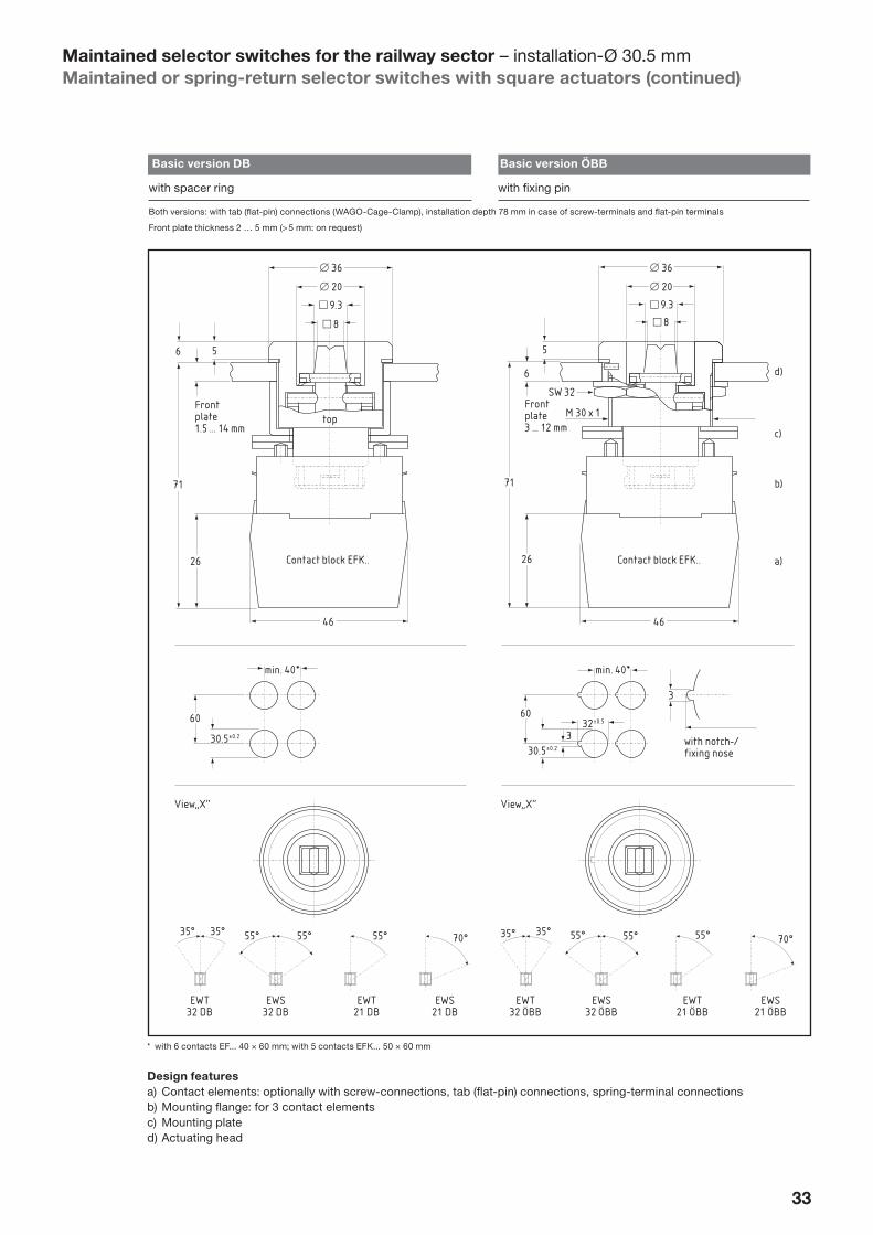
Maintained selector switches for the railway sector – installation-Ø 30.5 mmMaintained or spring-return selector switches with square actuators
Design
Instead of a grip as in stand-ard commercially available maintained or spring-return selector switches, these device versions are actuated by means of a square tool (or – on request – a triangu-lar tool). They are familiar as ”train-guard switches” because this kind of device is used to close railway car-riages.
This tool aids in ensuring that the devices cannot be actuated at will. Com-pared to the key-operated maintained or spring-return selector switches the ad-vantage of these switches is that they are less sensitive to ambient infl uences, such as dust, dirt etc.
Technical data
Protection type IP 65 (IP 67 on request)
Actuating force max. 16 Nm
Temperature range –40 °C … + 80 °C
Materials • Actuating heads: robust metal version, optionally 2- or 3-digit
• Front ring: Al Mg Si Pb F20, decorative anodised• Square actuator acc. to BN 421 007: Cu Zn 39 Pb 3 –
chromed
Switching angle refer to fi gures
Installation boring acc. to EN 50 007
30.5+ 0.2 mm
Grid dimension • with 6 contacts EF...: min. 40 × 60 mm• with 5 contacts EFK...: min. 50 × 60 mm
Contact assembly • max. 6 contacts (NC or NO – optional) in case of screw connections and tab (fl at-pin) connections, installation depth 78 mm
• max. 5 contacts (NC or NO – optional) in case of spring-terminal connections (WAGO-Cage-Clamp), installation depth 68 mm
Front plate thickness depending on version 1.5 … 14 mmContact elements refer to pages 34 et seq. (the preferred contact elements are – by reason of contact safety, especially in case of shock- and vibration forces – the type EFK… contact elements [refer to page 38]; all other contact elements with screw connections and tab (fl at-pin) connections are also applicable).
Maintained or spring-return selector switches with square actuators
Brief description Type Catalogue no. Order no.
2-digitwith square actuator
momentary contact EWT21DBEWT21ÖBB
027 2015027 2016
103 0851105 1542
switching contact EWS21DBEWS21ÖBB
027 2061027 2062
105 1548105 1543
3-digitwith square actuator
switching contact EWS32DBEWS32ÖBB
027 2081027 2082
105 1546105 1541
momentary contact EWT32DBEWT32ÖBB
027 2025027 2027
102 8782105 1463
Version with triangular actuator: on request
Type EWT32ÖBB; for more detailed explanations of the elements refer to „Design features“ (page 33)
a) b) c) d)
33
* with 6 contacts EF... 40 × 60 mm; with 5 contacts EFK... 50 × 60 mm
Design features
a) Contact elements: optionally with screw-connections, tab (fl at-pin) connections, spring-terminal connectionsb) Mounting fl ange: for 3 contact elementsc) Mounting plated) Actuating head
View„X“
EWT32 DB
35° 55° 55° 55° 70°35°
EWS32 DB
EWT21 DB
EWS21 DB
top
46
26
71
Contact block EFK..
36
56
20
9.3
8
Front plate1.5 … 14 mm
min. 40*
30.5±0.2
60
View„X“
EWT32 ÖBB
EWS32 ÖBB
EWT21 ÖBB
EWS21 ÖBB
36
5
6
20
26
71
46
Contact block EFK..
9.3
8
SW 32
M 30 x 1Front plate3 … 12 mm
min. 40*
with notch-/fixing nose
32±0.5
30.5±0.2
60
3
3
a)
b)
c)
d)
35° 55° 55° 55° 70°35°
Basic version DB Basic version ÖBB
with spacer ring with fi xing pin
Both versions: with tab (fl at-pin) connections (WAGO-Cage-Clamp), installation depth 78 mm in case of screw-terminals and fl at-pin terminals
Front plate thickness 2 … 5 mm (> 5 mm: on request)
Maintained selector switches for the railway sector – installation-Ø 30.5 mmMaintained or spring-return selector switches with square actuators (continued)
34
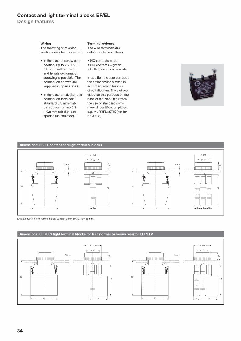
Contact and light terminal blocks EF/EL
Design features
Wiring
The following wire cross sections may be connected:
• In the case of screw con-nection: up to 2 × 1.5 … 2.5 mm2 without wire-end ferrule (Automatic screwing is possible. The connection screws are supplied in open state.).
• In the case of tab (fl at-pin) connection terminals: standard 6.3 mm (fl at-pin spades) or two 2.8 × 0.8 mm tab (fl at-pin) spades (uninsulated).
Terminal colours
The wire terminals are colour-coded as follows:
• NC contacts = red• NO contacts = green• Bulb connections = white
In addition the user can code the entire device himself in accordance with his own circuit diagram. The slot pro-vided for this purpose on the base of the block facilitates the use of standard com-mercial identifi cation plates, e.g. MURRPLASTIK (not for EF 303.S).
Dimensions: EF/EL contact and light terminal blocks
Dimensions: ELT/ELV light terminal blocks for transformer or series resistor ELT/ELV
(Overall depth in the case of safety contact block EF 303.S = 65 mm)
46
60
max. 6
46
60
max. 6
10
52
¤ 22
¤ 29,5
14
10 10
52
10
¤ 22
¤ 29,5
14
30
52
10
¤ 22
¤ 29,6
14
30
52
¤ 22
¤ 29,6
14
46
60
max. 6
46
60
max. 6

35
Contact blocks with screw connection terminal
Function/contact path diagram Mounting fl ange position1 Type Catalogue
no.
Order no.
1 NC2 Pos. 1Pos. 2Pos. 3
EF10.1EF10.2EF10.3
028 0010028 0020028 0030
100 6535100 6536100 6537
1 NO Pos. 1Pos. 2Pos. 3
EF03.1EF03.2EF03.3
028 0040028 0050028 0060
100 6538100 6539100 6540
2 NC2 Pos. 1Pos. 2Pos. 3
EF110.1EF110.2EF110.3
028 0070028 0080028 0090
100 6541100 6542100 6543
2 NO Pos. 1Pos. 2Pos. 3
EF033.1EF033.2EF033.3
028 0100028 0110028 0120
100 6544100 6545100 6546
1 NC/1 NO2 Pos. 1Pos. 2Pos. 3
EF103.1EF103.2EF103.3
028 0130028 0140028 0150
100 6547100 6548100 6549
1 NC/1 NO2 Pos. 1Pos. 2Pos. 3
EF301.1EF301.2EF301.3
028 0160028 0170028 0180
100 6550100 6551100 6552
for EMERGENCY STOP-command devices
1 NC/1 NO Pos. 1Pos. 2
EF 303.1EF 303.2
028 1360028 1365
102 2137102 2138
2 NC Pos. 1Pos. 2
EF 220.1EF 220.2
028 1382028 1384
102 3927102 4262
1 NC/1 NOwith safety spring3
Pos. 1Pos. 2
EF 303S.1EF 303S.2
028 1300028 1310
100 6584100 6585
1 The terminal identifi cation of the contacts in accordance with DIN 50 005 incorporate a complete function and order code. The function
code identifi es NC or NO contacts, the order code gives the number and sequence of the contacts in the complete switch device. We
therefore recommend that the mounting fl ange position the contact blocks are to be snapped on to is established when designating type.
2 Not admissible for EMERGENCY STOP.
3 The contact blocks EF 303S... have a safety spring which guarantees perfect functioning even if the spring breaks. This is achieved by
special guidance and coiling of the reset spring. Name plates in the groove on the lower side of the block cannot be used in this variation
since the plunger for the safety spring requires a larger lift.
Contact and light terminal blocks EF/EL
Contact blocks with screw connection terminal
Terminal identifi cation
Function Pos. 1 Pos. 2 Pos. 3
1 NC 11-12 21-22 31-32
1 NO 13-14 23-24 33-34
2 NC 11-12/21-22 31-32/41-42 51-52/61-62
2 NO 13-14/23-24 33-24/43-44 51-52/63-64
1 NC, 1 NO 11-12/23-24 31-32/43-44 51-52/63-64
1 NC/1 NO 11-12/23-24 31-32/43-44 51-52/63-64
1 NC/1 NO switching together 11-12/23-24 31-32/43-44 51-52/63-64
Technical data: see page 44.
Dimensions: see page 34.

36
Contact and light terminal blocks EF/EL
Contact blocks with tab (fl at-pin) connection terminal
Terminal identifi cation
Function Pos. 1 Pos. 2 Pos. 3
1 NC 11-12 21-22 31-32
1 NO 13-14 23-24 33-34
2 NC 11-12/21-22 31-32/41-42 51-52/61-62
2 NO 13-14/23-24 33-24/43-44 51-52/63-64
1 NC, 1 NO 11-12/23-24 31-32/43-44 51-52/63-64
1 NC/1 NO 11-12/23-24 31-32/43-44 51-52/63-64
1 NC/1 NO switching together 11-12/23-24 31-32/43-44 51-52/63-64
Technical data see pages 44–45.
Dimensions: see page 34.
Contact blocks with tab (fl at-pin) connection terminal
Function/contact path diagram Mounting fl ange position1 Type Catalogue
no.
Order
no.
1 NC2 Pos. 1Pos. 2Pos. 3
EF10F.1EF10F.2EF10F.3
028 1010028 1020028 1030
100 6560100 6561100 6562
1 NO Pos. 1Pos. 2Pos. 3
EF03F.1EF03F.2EF03F.3
028 1040028 1050028 1060
100 6563100 6564100 6565
2 NC2 Pos. 1Pos. 2Pos. 3
EF110F.1EF110F.2EF110F.3
028 1070028 1080028 1090
100 6566100 6567100 6568
2 NO Pos. 1Pos. 2Pos. 3
EF033F.1EF033F.2EF033F.3
028 1100028 1110028 1120
100 6569100 6570100 6571
1 NC/1 NO2 Pos. 1Pos. 2Pos. 3
EF103F.1EF103F.2EF103F.3
028 1130028 1140028 1150
100 6572100 6573100 6574
1 NC/1 NO2, 3 Pos. 1Pos. 2Pos. 3
EF301F.1EF301F.2EF301F.3
028 1160028 1170028 1180
100 6575100 6576100 6577
for EMERGENCY STOP-command devices
1 NC/1 NO Pos. 1Pos. 2
EF 303F.1EF 303F.2
028 1375028 1380
102 2140102 2141
2 NC Pos. 1Pos. 2
EF 220F.1EF 220F.2
028 1388028 1390
102 4291102 4292
1 NC/1 NOwith safety spring3
Pos. 1 EF 303F.1 028 1330 100 6587
1 The terminal identifi cation of the contacts in accordance with DIN 50 005 incorporate a complete function and order code. The function
code identifi es NC or NO contacts, the order code gives the number and sequence of the contacts in the complete switch device. We
therefore recommend that the mounting fl ange position the contact blocks are to be snapped on to is established when designating type.
2 Not allowed for EMERGENCY STOP.
3 The contact blocks EF 303S... have a safety spring which guarantees perfect functioning even if the spring breaks. This is achieved by
special guidance and coiling of the reset spring. Name plates in the groove on the lower side of the block cannot be used in this variation
since the plunger for the safety spring requires a larger lift.
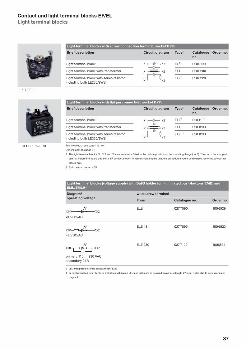
37
Light terminal blocks with fl at pin connection, socket Ba9S
Brief description Circuit diagram Type1 Catalogue
no.
Order no.
Light terminal block ELF2 028 1190
Light terminal block with transformer ELTF 028 1200
Light terminal block with series resistor including bulb LE230/9WS
ELVF2 028 1290
Technical data: see pages 39–40.
Dimensions: see page 34.
1 The light terminal blocks EL, ELT and ELV are only to be fi tted to the middle position on the mounting fl ange (no. 3). They must be snapped
on fi rst, before fi tting any additional EF contact blocks. When dismantling the unit, the procedure should be reversed removing all contact
blocks fi rst.
2 Bulb centre contact = X1
Light terminal blocks with screw connection terminal, socket Ba9S
Brief description Circuit diagram Type1 Catalogue
no.
Order no.
Light terminal block EL2 028 0190
Light terminal block with transformer ELT 028 0200
Light terminal block with series resistor including bulb LE230/9WS
ELV2 028 0220
Contact and light terminal blocks EF/EL
Light terminal blocks
Light terminal blocks (voltage supply) with Ba9S holder for illuminated push-buttons EME3 and
EML/EMLH4
Diagram/
operating voltage
with screw terminal
Form Catalogue no. Order no.
24 VDC/AC
ELE 027 7090 100 6529
48 VDC/AC
ELE 48 027 7095 100 6532
primary 115 … 230 VAC; secondary 24 V
ELE 230 027 7100 1006534
3 LED integrated into the indicator light EME
4 or for illuminated push-buttons EDL if socket-based LEDs or bulbs are to be used (maximum length 27 mm). Refer also to accessories on
page 48.
EL/ELF/ELE
ELT/ELTF/ELV/ELVF

38
Contact and light terminal system EFK/ELK
with WAGO-Cage-Clamps
Dimensions contact and light terminal blocks EFK/ELK, here: 1-pole contact and light terminal blocks
Front plate thickness 1.5 … max. 6 mm, mounting fl ange belongs to the delivery status.
* Dimensions of base module
Dimensions contact and light terminal blocks EFK/ELK, here: 2-pole contact and light terminal blocks
Front plate thickness 1.5 … max. 6 mm, mounting fl ange belongs to the delivery status.
* Dimensions of base module
** max. 1 × 2-pole element recommended
5151
max. 6 max. 614*
∅ 22
∅ 29,5
14
∅ 29,5*
∅ 22
2010 10
∅ 22
∅ 29,5
14
46
51
max. 6

39
Contact terminal blocks with with tab (fl at-pin) connection terminal,
here: 2-pole contact terminal blocks
Function/
contact path diagram
Mounting fl ange position Type Catalogue
no.
Order
no.
Contact terminal block 2 NC, contact way 2 × 3 mm EFK330.1EFK330.2
028 1008028 1009
116 2285116 2286
Contact terminal block 2 NO, contact way 2 × 3 mm EFK033.1EFK033.2
028 0996028 0997
116 7605116 7606
Contact terminal block1 1 NC/1 NO, contact way 1/3 mm
EFK103.1EFK103.2
028 1000028 1004
116 7603116 7604
1 Not admissible for EMERGENCY STOP devices
The terminal identifi cation of the contacts in accordance with DIN 50 005 incorporate a complete function and order code. The function code
identifi es NC or NO contacts, the order code gives the number and sequence of the contacts in the complete switch device. We therefore
recommend that the mounting fl ange position the contact blocks are to be snapped on to is established when designating type.
Terminal identifi cation: See page 36.
Contact and light terminal blocks with with tab (fl at-pin) connection terminal,
here: 1-pole contact and light terminal blocks
Function/
contact path diagram
Mounting fl ange position Type Catalogue
no.
Order
no.
Contact terminal block1 1 NC, contact way 1 mm EFK10.1EFK10.2EFK10.3
028 1001028 1002028 1003
102 2275102 2276102 2277
Contact terminal block 1 NC, contact way 3 mm EFK30.1EFK30.2EFK30.3
028 1005028 1006028 1007
102 6057102 6058102 6059
Contact terminal block 1 NO, contact way 3 mm EFK03.1EFK03.2EFK03.3
028 1066028 1067028 1068
102 2272102 2273102 2274
Light terminal block ELK 028 1196 102 2278
1 Not admissible for EMERGENCY STOP devices
0 2 4 6 mm
0 2 4 6 mm
0 2 4 6 mm
0 2 4 6 mm
0 2 4 6 mm
0 2 4 6 mm
Contact and light terminal system EFK/ELK
with WAGO-Cage-Clamps (continued)

40
Assembly instructions
Cage clamp terminals are simple and easy to handle.
• The EFK and ELK contact and light terminal blocks are admissible for insu-lated copper wires of 0.08 … 1.5 mm2 (splice protec-tion is not necessary, but possible).
• One conductor per terminal point is provided (in many standards and regulations “one conduc-tor per terminal point” is prescribed or recommend-ed), but the EFK and ELK contact and light terminal blocks have double termi-nals to facilitate the loop-ing through of conductors.
• The WAGO-cage-clamps are front-wired as follows:1. Clamp opened by means of screwdriver.2. Conductor pushed in.3. Clamp closed by pulling out screwdriver.
• Dismantling is performed in reverse order. Step 2: conductor removed.
Contact and light terminal blocks EFK/ELK
with WAGO-Cage-Clamps)(continued)
Light terminal blocks (voltage sensor) with socket Ba9S for pilot lights NME/NMEF1 and NML/NMLH
Diagram/
operating voltage
Type Catalogue no. Order no.
24 VDC/AC
ELEK 027 7096 116 7368
1 or for illuminated push-buttons EDL, when socketed LED’s shall be used (max. length 27 mm). See also accessories page 48 et seq.
Light terminal blocks with integrated Multi-LED für illuminated pushbuttons NDL and pilot lights
NML/NMLH
Diagram/
operating voltage
Colour Type Catalogue no. Order no.
24 VDC/AC
rotgelbgrünblauweiß
ELDEK RTELDEK GBELDEK GNELDEK BLELDEK WS
027 6650027 6651027 6652027 6653027 6654
116 7381116 7382116 7383116 7384116 7385
Cable CableScrew- driver
Screw- driver

41
Contact and light terminal blocks EFP/ELP
with printed circuit board connection
Advantages
In addition to the square VZ range for device instal-lations in a grid spacing of 25 × 25 mm, printed circuit board connections in the Elan range are now available also for control devices and indicator lights for 22.3 mm fi tting holes. This increasing-ly updated connection tech-nology replaces traditional device wiring with screw terminals or fl at pin plugs. Signal and control linkage of the wiring is taken care of by the printed circuit.
The main advantages of the printed circuit board con-nections are:
• wiring work per operating panel or command panel is reduced
• incorrect wiring is impos-sible, thus:• saving on time – par-
ticularly in the case of complex arrangements – for trouble-shooting and fault rectifi cation
• assembly time is reduced by numerous additional design advantages of the entire range
Product range
In order to offer universal use the printed circuit board connection in the new contact and light terminal blocks is compatible with all actuators of the EF/EL range. Actuators and indica-tor lights are available for:
• tough applications with metal bezel, metal buttons as well as glass for lenses of illuminated devices
• fl exible snap-in symbols• normal industrial applica-
tions in plastic
Design features
Contact and light terminal blocks with printed circuit board connections are snapped on to the mount-ing fl ange in the tried and tested manner with stain-less steel clips. The printed
circuit board connection is connected via a sepa-rate push-in plug. Machine welding is thus possible without additional measures. All main features of the EF/EL range such as single-hand assembly, modularity, terminal identifi cation etc. are also available. A maxi-mum of three blocks can be mounted.
A special fi xing element is available to fi x the printed circuit board to the front panel; it accommodates a screw connection from the rear side of the board, thus saving additional measures for spacing. Depending on size and structure of the front panel, this element is snapped on to the individual free positions of the mount-ing fl ange.
Contact blocks are offered either with 1 NC or with one NO contact. The Elan four-way contact acts as contact bridge system also in the elements with printed circuit board connection. This Elan four-way contact:
• functions even at lowest voltage enabling the actu-ation of voltages and cur-rents as from 5 V/3.2 mA and powers up to 480 VAC or 450 VDC.
The printed circuit board connections have two solder lugs per connection point. The admissible current load is 5 A. Two soldering eyelets are required per connection point. This produces a high degree of reliability of the solder connection.
The 0.8 × 1.6 mm pin con-nections intended for as-sembly in the recepticle are also suitable for connections of commercially available one-pole individual plug (AMP type MODU 1).
1
.1
3 2
EFM
.3 .2
1
.1
3 2
ELM
.2

42
Contact and light terminal blocks EFP/ELP
with printed circuit board connection (continued)
Contact and light terminal blocks with printed circuit board connection
Brief description Function Mounting fl ange
position
Type Catalogue
no.
Order
no.
Contact block1 1 NC Pos. 1Pos. 2Pos. 3
EFP10.1EFP10.2EFP10.3
028 1033028 1034028 1035
102 0830102 0831102 0832
Contact block 1 NO Pos. 1Pos. 2Pos. 3
EFP03.1EFP03.2EFP03.3
028 1063028 1064028 1065
102 0827102 0828102 0829
Light terminal block for Ba9s lamp base Pos. 3 ELP 028 1197 102 0826
Fixing element EFB 028 1410 102 0931
Recepticle EP 028 1400 102 0932
Dimensions contact and light terminal blocks EFP/ELP
30±0.1
20±0.1
1.6
3.2
35
26
10
3
(21)
(11)
(X2)
(22)
(12)
(X1)
Dimensions recepticle EP
30±0.1
Element 2
Mounting hole ∅ 2.8
Element 3
Element 1
20±0.1
1.85±0.05
2.9±0
.05
46
30
21X1
1112X2
22
Hole pattern for EP recepticle
46
max. 6
10 1010
14
51
1,5
∅ 29,5
∅ 22
46
max. 6
10
14
51
1,5
∅ 29,5
∅ 22

43
46
Cylindrical screw M 2.5
10
39
30
Cross section fi xing block EFB
EFM
31 2
ELM
31 2
3111 21
3212 22
X211 21
X212 22
Example complete complement EFP/ELP
Terminal identifi cations
Function Pos. 1 Pos. 2 Pos. 3
1 NC contact 11-12 21-22 31-32
1 NO contact 13-14 23-24 33-34
Light terminal block – – X1-X2
Installation hole with posi-
tioning aid
The lug cut-outs are merely a recommendation by way of positioning-aid. Punch tools or other assistance in this connection on request.
4.2±0.05
22.3±0.1
23.5±0.1
Contact and light terminal blocks EFP/ELP
with printed circuit board connection (continued)

44
Contact and light terminal blocks
Technical data
Control devices and indicator light actuators, type E..
Protection type IP 67/65
Temperature range –25 … + 75 °C, Illuminated push-button: max. 40 °C ambient temperature
Bulb replacement using bulb remover from front, bulb type Ba9s
Options Low temperature versions –40 °C: on request
Contact blocks and light elements EF/EL
Regulations Industrial switchgear to EN IEC 60 947-5-1
Rated insulation voltage • Contact element: 400 V• Illuminated element: 250 V
Rated insulation voltage Ui at pollution degree 3 acc. IEC 60 947-1
440 V
Rated impulse withstand voltage Uimp 2,5 kV
Galvanic separation of contact bridges yes
Thermal-rated current Ith (in air) 10 A
Rated operating current Ie acc. to application category and rated operational voltage Ue
• 8 A, AC-15, 250 VAC• 5 A, DC-13, 24 VDC (restriction: cable cross-section max. 1 × 2.5 mm2 –
use only same diameter)
Low voltage capability 5 VDC/3.2 mA
Short-circuit protection gG 10 A
Proof of positive opening 2.5 kV surge
Positive opening way approx. 2 mm after reaching the opening point
Lamps (Ba9S) Light bulb (max. 2 W), LED
Air and creepage distance acc. DIN EN 60 664-1
4 kV/3
Switching frequency 1,200 s/h
Switching points • NC: approx. 1 mm• NO: approx. 2.5 mm
Shock resistance 110 g/4 ms – 30 g/18 ms, no chatter
Vibration resistance > 20 g/10 … 200 Hz (correspondingly lower in the case of actuators with bigger dimensions)
Bounce time (100 mm/s) < 5 ms
Temperature range • Contact element: –25 … + 70 °C• Light element (Ba9S) with LED (make Elan) –25 … + 60 °C• Light element (Ba9S) with light bulb (max. 2 W) –25 … + 45 °C
Climatic resistance Part 2-20
Installation position any
Mechanical life acc. IEC 60 947-5-1 10 × 106 switching cycles
Contacts, connection terminals fi ne silver, spring bronze or brass carrier
Contact force 0.5 N per contact ∧= 2 N per contact bridge
Actuating force • at 2 mm lift: 4 N• at 4 mm lift: 7 N• at 6 mm lift: 9 N
Terminal markings acc. IEC 60 947-1
* insofar as not specifi ed elsewhere

45
Contact blocks and light elements EF/EL (continued)
Type of mounting • Screwed connection• Tab (fl at pin) connection• Cage-clamp connection
Mounting diameter • Single core: 2 × (0.5 … 2.5 mm2)• Dual core with wire-end ferrule: 2 × (0.5 … 1.5 mm2)
Connections • see page 33
Tightening torque of the connection terminals 0.8 Nm
Contact protection existing (acc. to EN 50 274 and BGV A2)(except light element, sole mounted)
Protection category • Connections: IP 20 (fi nger-safe)• Switching elements: IP 40
Approvals cULus
Contact and light terminal blocks
Technical data (continued)

46
Accessories
Identifi cation plates installation diameter 22.3 mm
Brief description Type Catalogue
no.
Order
no.
Aluminium version, aluminium colour-anodised, with sealInscription area: dark grey RAL 7012Inscription area: 8 mm × 28 mm1 line: max. 8 letters, 5 mm high1 line: max. 11 letters, condensed type, 4 mm high2 lines: per line max. 13 letters, condensed type, 2 mm high
MZSO 070 1211 100 1406
Plastic versionInscription area stick-in, dark-grey RAL 7021, aluminium-colour anodised highlighted, inscription area: 10 × 26 mm1 line: max. 8 letters, 5 mm high1 line: max. 10 letters, condensed type, 4 mm high2 lines: per line max. 12 letters, condensed type, 2 mm high
KZSO 070 1100 102 2486
15
25
22.5
30
15
30
22.5
30
MZSO
KZSO
Identifi cation plates installation diameter 30.5 mm
Brief description Type Catalogue
no.
Order
no.
Aluminium version, aluminium colour-anodised, with sealInscription area: dark grey RAL 7012Inscription area: 13 mm × 38.4 mm1 line: max. 11 letters, 5 mm high1 line: max. 15 letters, condensed type, 4 mm high2 lines: per line max. 18 letters, condensed type, 2 mm high
ZSO 070 0509 100 0953
Aluminium version, aluminium colour-anodised, with sealInscription area: dark grey RAL 7012Inscription area: 9 mm × 38.4 mm1 line: max. 11 letters, 5 mm high1 line: max. 15 letters, condensed type, 4 mm high2 lines: per line max. 18 letters, condensed type, 2 mm high
ZSO2 070 0916 100 9072
like ZSO, but black anodisedInscription area: aluminium-colour bordered
ZSNO 070 0312 100 9064
20
29
30.5
40
ZSO
20
34
30,5
40
ZSO2
20
34
30,5
40
ZSNO

47
Front panel seal made of PTFE (acid-resistant) with Tefl on rings
Brief description Type Catalogue
no.
Order
no.
Installation diameter 22.3 mm:
Front panel sealMDT-8/PTFE 071 6815 102 2503
Installation diameter 30.5 mm:
Front panel sealDTN-28/PTFE 071 6820 119 3506
MDT-8/PTFE
Blindstopfen für Leer-Einbaustellen
Brief description Type Catalogue
no.
Order
no.
Installation diameter 22.3 mm:
Aluminium, anodised, with sealFront panel thickness: 1.5–6 mm
MBN 071 6201 100 9241
Installation diameter 30.5 mm:
Aluminium, anodised, with sealFront panel thickness: 1.5–6 mm
BN 071 0300 100 9118
1 … 6 mm
5.5
22.3
30
MBN
s
5.5
∅ 30
∅ 38
BN
DTN-28/PTFE
Accessories (continued)

48
Adapter ring with seal for insertion of 22.5 mm ∅ actuators in 30.5 mm holes
Brief description Type Catalogue
no.
Order no.
Aluminium, anodised, with seal and thrust washerThe maximum front panel thickness is thus reduced to 4 mm.
MUE 071 7908 101 7057
22.5
29.5 38
Miscellaneous
Brief description Type Catalogue
no.
Order no.
Spare key• for EDS/KDS... devices (lock 13 220)• for devices with CES lock (lock EKM 30)
SDS 1SDS 2
072 1166072 1191
100 0662100 1629
Bulb remover E-LR-4 071 3230 100 9178
Mounting tool for bulb replacement K-14 071 4300 100 2313Spare key SDS 1
Bulb remover E-LR-4
Accessories (continued)
Mounting tool for bulb replacement
K-14
Adapter ring MUE

49
Bulbs1
Incandescent bulbs
Operating voltage
(Volt)
Bayonet socket Ba9S Catalogue
no.
Order no.
Power Type
6 2 W L6/9 069 0104 100 1221
12 2 W L12/9 069 0325 100 1222
24 1.9 W L24/9 069 0406 100 1223
30 2 W L30/9 069 0554 100 1224
48 1.9 W L48/9 069 0651 100 1226
60 2 W L60/9 069 0562 100 1227
110–1301 2.4 W L130/9 069 0595 100 1230
Neon bulbs
Operating voltage
(Volt)
Bayonet socket Ba9S Catalogue
no.
Order no.
Power Type
110 – LN110/9 069 0881 100 1209
220 – LN220/9 069 1089 100 1210
Multi-LED’s white with Ba9S socket
Operating voltage
(Volt)
Bayonet socket Ba9S Catalogue
no.
Order no.
Power Type
24 V AC/DC – LE24/9 WS 069 0030 103 0894
230 V AC – LE230/9 WS 069 0031 118 6864
28
max. 10
Ø 10
25
Multi-LED LE 24/9 WS
46.4
45.2
18.8
7
Snap-on cover EL-15
Incandescent bulbs L../9
neon bulbs LN.../9
Accessories
Version Type Catalogue
no.
Order no.
Snap-on cover2 EL-15 071 3005 100 2367
1 Use of socketed LEDs (Ba9S) “super-bright”: on request.
2 Measure to protect against contact in the case of illuminated push-buttons with shock hazard
operating voltage. The snap-on cover covers unused mounting fl ange positions and prevents
contact with live parts.

50
Light-metal panel mounting boxes
These housings consist of a strong light alloy casting. They are therefore robust and rugged. The seal is de-signed in such a way that the fi xing holes for the housing lie outside the lid seal and the reliable encapsulation is thus not impaired. The de-sign provides protection to class IP 65. If identifi cation plates are used, the seals supplied should be inserted.
The housings and the lid are coated inside and out with corrosion-resistant stove-enamelled paint as follows:• Basic housing: dark grey
RAL 7012• Lid or front plate: silver
grey RAL 9006
Control and indicator devices can be accomo-dated in the boxes in widely differing arrangements. The size of the required fi tting hole centres either 30 mm1, 40 mm or 50 mm.
The front cover, once re-moved, can only be screwed back on in one specifi c position. This is achieved by means of a cast projecting lug on the shorter side of the housing.
Metric cable gland holes
Panel mounting boxes are supplied with 1 tapped hole M20; from housing length of 245 mm, M25 on the shorter side or on the right in the case of horizontal arrange-ment (excluding compres-sion gland fi ttings).
On request and at extra cost, panel mounting boxes are available with the follow-ing tapped holes and also with metal compression gland fi ttings:On one or both shorter sides• 2 × M20 × 1.5 or• 1 × M25 × 1.5.
1 With 30 mm distance between
holes, 10 mm additional width is to
be allowed for when mounting the
ELT transformer block and the ELV
light terminal box with series resis-
tor (see pages 34 et seq.).
Dimensions light-metal panel mounting boxes
Fixing holes light-metal panel mounting boxes
aL
a
85 5.5
MBG 311
MBG 433
807174
L – 35
2
M5
70
54
13
25
202
2: Total length – 35 mm is distance between the mounting holes.
Total length L of the building enclosure: see page 51

51
Light-metal panel mounting boxes for installation diameter 22.3 mm
Control devices
centre “a”
Number
of control
devices
Length
L (mm)
Housing with
lid fi xing holes
Hole for cable
gland metric
Catalogue
no.
Order no.
30 mm1
for MZSO iden-tifi cation plates, horizontal arrangement
1 85 MBG 3111 M20 064 4994 100 8285
2 125 MBG 322 M20 064 5249 100 8297
3 165 MBG 333 M20 064 5494 100 8302
4 205 MBG 344 M20 064 5745 100 8306
5 205 MBG 345 M20 064 5991 100 8310
6 245 MBG 356 M25 064 6245 100 8315
8 305 MBG 368 M25 064 6491 100 8319
40 mm
für MZSO iden-tifi cation plates, horizontal and vertical arrange-ment
2 125 MBG 422 M20 064 6890 100 8324
3 165 MBG 433 M20 064 7144 100 8328
4 205 MBG 444 M20 064 7390 100 8332
5 245 MBG 455 M25 064 7641 100 8336
6 305 MBG 466 M25 064 7896 100 8340
50 mm
for MZSO identifi -cation plates, ver-tical and horizon-tal arrangement
2 165 MBG 532 M20 064 8299 100 8344
3 205 MBG 543 M20 064 8540 100 8349
4 245 MBG 554 M25 064 8795 100 8353
5 305 MBG 565 M25 064 9040 100 8357
With protective collar against unin-tentional actuation
1 85 MBGH 311MBGH 311 GB
M20M20
064 4995064 4997
100 8286100 8287
Availability of individual front panels, mounting boxes without lid fi tting holes and front panels without lid fi tting holes: on request.
1 Also available with a yellow lid.
Light-metal panel mounting boxes
Product range
MBGH 311 GB
Dimensions light metal panel mounting boxes with and without protective collar against unintentional actuation
60
50
70
14
26 3
8.2
30
M 20
85 20
85
22.3
22
74
5
28
55
5.6
64
MBG..MBGH..
1:21:2

52
MBG 543.5
MB for control deviceswith 22.3 mm fi ttinghole diameter
G = mounting box,F = front panel
Suffi x for horizontal asymmetri-cal version
Number of control units(0 for lid with no hole bored)
Length of panel box orfront panel
Hole centre distance of control devices (1 for lid with no unit hole bored)
Light-metal panel mounting boxes (front installation diameter 22.3 mm)
Versions, inscriptions and symbols
In addition to the colour-ing of the Control devices and indicator lamps, further identifi cation by means of symbols and inscriptions is often advisable and ap-propriate.
The following possibili-ties are provided for this purpose:• Symbols on the button or
under the fl at glass lens (see page 60)
• Inscriptions on individual name plates MZSO (see page 46)
For panel boxes and front
panels with symmetrical
arrangements of Control
devices and indicator
lamps:
1) with individual MZSO identifi cation plates (50 mm distance between centres necessary)
Attention: Engravings cannot be provided on the control device surround. They can only be provided on the moving part of the push-button or in illuminated push-buttons and indicator lights.
For panel boxes and front
panels with asymmetrical
arrangements of Control
devices and indicator
lamps 7 mm notwithstand-
ing the middle:
2) with individual MZSO identifi cation plates (for horizontal arrangement only)
• without name plates: Suffi x .5
Please order individual
identifi cation plates
always separately (refer to
the list of the necessary
sizes at page 53).
Yellow EMERGENCY STOP
discs
53 mm outside diameter to fi t panel boxes and front panels with a minimum hole centre distance a = 50 mm necessary, see page 7.
For ∅ 22.3 mm control de-vices and indicator lamps:Type MDP-8
Explanation of the type designation
When ordering please specify the following:• Size of panel box or front
panels.• Details of the Control
devices and indicator lamps to be fi tted includ-ing colour, inscription and symbols on the bottom or to be fi tted in the fl at disk on the lens head (applies only to fi tted devices).
• Details of additional or other M-cable gland tapped holes.
• Metal-compression gland fi ttings.
• Identifi cation plates (EMERGENCY STOP disks), individual name plates or common alu-minium name plate).
7*
1. 2.
* 7 mm notwithstanding the middle
Example

53
Light-metal panel mounting boxes for installation diameter 30.5 mm – vandal proof devices
Control devices
centre “a”
Number
of control
devices
Length
L (mm)
Housing with
lid fi xing holes
Hole for cable
gland metric
Catalogue
no.
Order no.
40 mm1
without identifi ca-tion plates
1 85 BG 4111 M20 064 0794 100 8209
2 125 BG 422 M20 064 1090 100 8228
3 165 BG 433 M20 064 1391 100 8232
4 205 BG 444 M20 064 1693 100 8237
5 245 BG 455 M25 064 1995 100 8241
6 305 BG 466 M25 064 2291 100 8246
50 mm
für ZSO2 iden-tifi cation plates, vertical arrange-ment
2 165 BG 532 M20 064 2592 100 8250
3 205 BG 543 M20 064 2894 100 8254
4 245 BG 554 M25 064 3149 100 8258
5 305 BG 565 M25 064 3394 100 8263
65 mm
for ZSO2 and ZSO identifi cation plates, vertical arrangement
2 205 BG 642 M20 064 3646 100 8267
3 245 BG 653 M25 064 3891 100 8273
4 305 BG 664 M25 064 4145 100 8280
With protective collar against unin-tentional actuation
1 85 BGH 411BGH 411 GB
M20M20
064 0799064 1033
100 8212100 8220
Availability of individual front panels, mounting boxes without lid fi tting holes and front panels without lid fi tting holes: on request.
1 Also available with a yellow lid.
Light-metal panel mounting boxes
Product range
60
50
70
14
26 3
8.2
30
M 20
85 20
85
22.3
22
74
5
28
55
5.6
64
MBG..MBGH..
1:21:2
BGH 411 GB
Dimensions light metal panel mounting boxes with and without protective collar against unintentional actuation

54
MBG 543.1
BG for control deviceswith 22.3 mm fi ttinghole diameter
G = mounting box,F = front panel/ lid for BG housing
Suffi x for horizontal asymmetri-cal version
Number of control units(0 for lid with no hole bored)
Length of panel box orfront panel
Hole centre distance of control devices (1 for lid with no unit hole bored)
Light-metal panel mounting boxes (front installation diameter 30.5 mm)
Versions, inscriptions and symbols
In addition to the colour-ing of the Control devices and indicator lamps, further identifi cation by means of symbols and inscriptions is often advisable and ap-propriate.
The following possibili-ties are provided for this purpose:• Symbols on the button or
under the fl at glass lens (see page 62)
• Inscriptions on individual name plates ZSO and ZSO2 (see page 46)
For panel boxes and front
panels with symmetrical
arrangements of control
devices and indicator
lamps:
1) with individual identifi ca-tion plates ZSO/ZSO2 (50 mm distance between centres necessary)
Attention: Engravings cannot be provided on the control device surround. They can only be provided on the moving part of the push-button or in illuminated push-buttons and indicator lights.
For panel boxes and front
panels with asymmetrical
arrangements of control
devices and indicator
lamps 7 mm notwithstand-
ing the middle:
2) with individual MZSO identifi cation plates (for horizontal arrangement only)
• without name plates: Suffi x .5
Please order individual
identifi cation plates
always separately (refer to
the list of the necessary
sizes at page 53).
Yellow EMERGENCY STOP
discs
53 mm outside diameter to fi t panel boxes and front panels with a minimum hole centre distance a = 50 mm necessary, see page 7.
For ∅ 30.5 mm control de-vices and indicator lamps:Type DPF-9
Explanation of the type designation
When ordering please specify the following:• Size of panel box or front
panels.• Details of the Control
devices and indicator lamps to be fi tted includ-ing colour, inscription and symbols on the bottom or to be fi tted in the fl at disk on the lens head (applies only to fi tted devices).
• Details of additional or other M-cable gland tapped holes.
• Metal-compression gland fi ttings.
• Identifi cation plates (EMERGENCY STOP disks), individual name plates or common alu-minium name plate).
Type-addendum:
7*
.2 .4
7*
.5

55
Al-cast housing construction
These enclosures are made of solid aluminum die casting. Therefore they are robust and insensitive. The seal is designed so that the mounting holes are outside of the housing cover seal and the reliability is not affected by encapsulation. This design allows protec-tion class IP 65.
The cases are completely powder coated to RAL 7001.
The control and signaling devices can be arranged in different variants. The frame size is determined here by the desired center distance between the holes of either 40 or 50 mm.
Gewinde bohrungen
The housing up to 200 mm have a threaded hole M20. From a housing length of 245 mm, a M25 threaded hole is on the narrow side down and left with horizon-tal mounting (without cable gland).
On request, the housings are available with metal fi t-tings or fully equipped with control devices.
t with horizon-(without cable
he housings with metal fi t-equipped with es.
Al-cast housing construction, colour RAL 7001 – powder anodised / IP 65 (W 100/H 80 mm)
Hole spacing
L
Number of
holes
(Ø 22.3 mm)
Length
(mm)
Housing type
with lid hole
Front side
hole metrical
Order no.
40 mm 1 100 MBGAC311 M20 121 3382
3 160 MBGAC433 M20 121 3383
4 200 MBGAC444 M20 121 3384
5 245 MBGAC455 M25 121 3385
6 305 MBGAC466 M25 121 3386
50 mm 2 160 MBGAC532 M20 121 3387
3 200 MBGAC543 M20 121 3388
4 245 MBGAC554 M25 121 3389
5 305 MBGAC565 M25 121 3390

56
100
10086
66
86
52
72
6652
132146
52 66
171186
6652
217231
6652
277291
5
160
L
146
200186
245231
245231
86
100 86
100 86
100 86
100 86
8020
1 25
R7
52
M4
¤8
8020
1
R7
52
M4
¤7
8020
1
R7
52
M4
¤7
8020
1
R7
52
M4
¤8
8020
1
R7
52
M4
¤8
5
5
5
5
LL
LLL
LLLL
25
25
25
25
Dimensions and bore holes housings made of light metal
Al-cast housing construction
Dimensions

57
Plastic panel mounting boxes
Glass-fi bre-reinforced versions
In addition to the feature of insulation-protected mount-ing with loop-through earth lead, the plastic housing offers the advantage of greater resistance to chemi-cal and use at temperatures between –40 … + 100 °C.
The plastic material used is self-extinguishing glass-fi bre reinforced polyamide. The protection class of the hous-ing corresponds to IP 67 in accordance with EN DIN 60 529. The standard colour of the mounting box and front lid is anthracite-grey. A yellow lid is available for the mounting of EMERGENCY STOP switches.
The plastic housing is de-signed with a 22.3 mm fi tting hole. Two “knock-out” holes are provided in the housing box for cable entries for the use of M20 plastic-threaded cable glands.
Dimensions and fi xing holes plastic panel mounting boxes
Plastic panel mounting boxes
Brief description Type Catalogue
no.
Order no.
Empty housing with lid, hole bored
MBK 311 066 0100 100 8556
Empty housing with yellow lid, hole bored
MBK 311 GB 066 0120 101 8717
Accessories: M20 plastic-threaded cable gland
M20 072 0258 100 9294
MBK 311 GB

58
Mounting boxes in ABS versions
This product range covers completely fi tted mounting boxes or control boxes. The appropriate control devices and indicator lights, option-ally with symbol or identi-fi cation plate, are already fi tted into the boxes.
The economic advantages are: • lower assembly times, • less warehousing and• administrative simpli-
fi cation of design and purchasing.
Technical data ABS mounting boxes
Protection type IP 65
Temperature range • – 25 °C … + 65 °C• in the case of illuminated push-
buttons: max. 40 °C ambient temperature
Bezel design RAL 7035, light grey
Housing colour RAL 7035 light grey
Material ABS
Resistances
Seawater resistant
Petrol not resistant
Weathering infl uences resistant
Hydrochloric acidup to 10%
resistant under certain conditions
Lactic acid resistant
Mineral bases resistant under certain conditions
Oils and greases resistant
Silicone oil resistant
Weak lyes resistant
UV resistant
Offered are:• a selection of standard
fi ttings undera single order number as well as
• freely selectable assem-blies of complete hous-ings.
Freely selectable assem-
blies of complete housings
The housings are supplied completely fi tted and ready to use with the required control devices and indica-tor lights, mounting hole 22.3 mm. The threaded cable entry isn’t part of the scope of delivery.
In the case of several instal-lation points the required M 20 entry will determine the order of fi tment.
The delivery of complete housings is made in accord-ance with the details of this catalogue. Other versions are available upon request, e.g. for devices with fi tting holes of 16.2 mm from Elan. These control devices and indicator lights can be pro-vided in grid spacing of 25 × 25 mm, thus facilitating a high packing density.
Order example
Task Order description
3-unit housing, cable entry at top Mounting box version KG 433-A Empty housing
fi tted with:
• pilot light with fl at lens, red, symbol “ON”
Installation point 1 EML RT Indicator light
515 Symbol (identifi cation plate)
EL Light terminal block
• Push-button black, symbol “tap”, 1 NC/1 NO
Installation point 2 EDT SW Push-button
405 Symbol
EF 103.1 Contact block
• EMERGENCY-STOP switchwith safety contact block
Installation point 3 EDRR 40 RT Impact button with latching
EF 303.S.1 Safety contact block
EFR Spring element
N.B.: Cable glands not supplied!
Accessories Form Catalogue no. Order no.
Steel mounting plate to protect against deforming of plastic front panel through fi xing screws of mounting fl anges
BK-8 071 0150 100 0553

59
Mounting boxes in ABS versions
Product range
Order information
Standard for M 20-connec-tion, correspond to letter A. Please order deviating ver-sions with a different letter (important for placement or fi tting).
ABS empty housings
Empty housing* M20-
position
Form Catalogue
no.
Order no.
A KG 411-A 066 2010 100 8565
B KG-411-S 066 2012 100 8566
C KG-411-C 066 2014 100 8567
D KG-411-D 066 2016 100 8568
A KG 422-A 066 2020 100 8569
B KG 422-B 066 2022 100 8570
A KG 433-A 066 2030 100 8573
B KG 433-B 066 2032 100 8574
A KG 432-A 066 2026 100 8571
B KG 432-B 066 2028 100 8572
A KG 443-A 066 2036 100 8575
B KG 443-B 066 2038 100 8576
Other versions (e.g. without boreholes): on request.
* Also available unfi tted under type reference KG 4... We recommend that steel-mounting plates (see accessories)
are placed beneath the front panel in order to protect the plastic material from deformation and damage from fi xing
screws.Cable glands not supplied!
A
C
BD
A
B
A
B
BA
BA
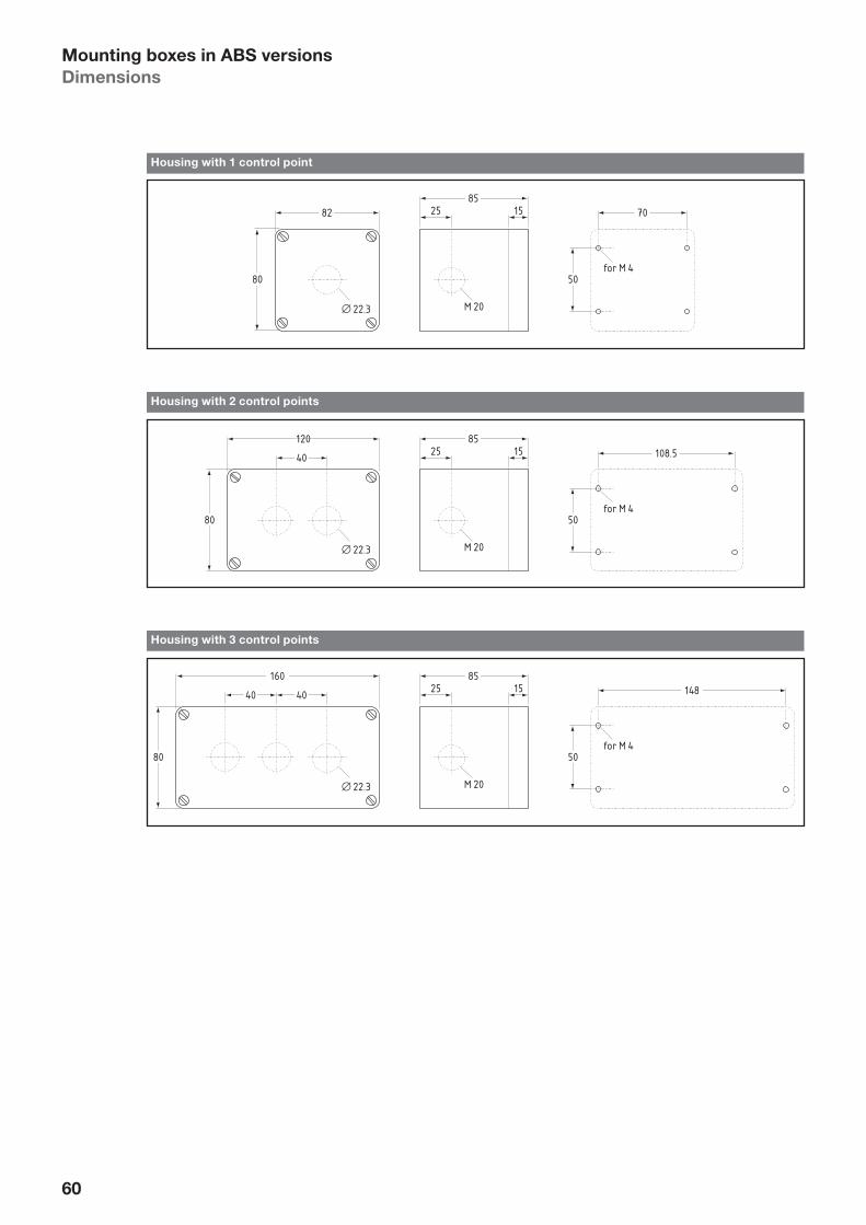
60
Mounting boxes in ABS versions
Dimensions
82 1525
M 20
80
85
for M 4
22.3
70
50
Housing with 1 control point
120
401525
M 20
80
85
for M 4
22.3
108.5
50
Housing with 2 control points
1601525
M 20
80
85
for M 4
22.3
148
50
4040
Housing with 3 control points

61
Notes

62
Symbols
Linear motion
101Working motion feed
102Rapid motion or idling
103Rapid motion
104Feed
105Interrupted motion jogging
106Reciprocating motion
107Limited motion
108Indexing
109Motion in 2 directions
Rotary motion
201Continuous clockwise rotation
202Anti-clock-wise rotation
203Clockwise rotation STOP
204Anti-clockwise rotation STOP
2051 revolution clockwise
206Anti-clock-wise
207Rotary indexing
208Interrupted rotary motion
209Clockwise motion restricted
210Anti-clock-wise motion restricted
211Clockwise motion from a restriction
211Anti-clockwise motion from a restriction
Additional options
301Clamping, chucking
302Release
303Braking
304Release brake
305Unlock
306Lock
1 20
II IIII
Arabic numerals1
700 701 702
801 802 803 1 Other numerals available, e.g. part no. 709 for number 9

63
Drives
401Electric motor
402Pump general
403Gear pump
405Coolant
406Oil lubrication
407Rotary indexing table
408Shuttle table forward
409Backwards
410Brake fan
411Caution – live
412Clamp table rectangular
413Electrical machine
Signals
501On
502Jog
503Automatic
504Off
505Everything off
506On – off
507Increase of a variable
508Decrease of a variable
509Pause (time elapse)
510Manual operation
511Visual
512Hydraulics
START STOP EIN AUS
RECHTS AUF ABLINKS
HALT VOLL LEERZU
Words
513 514 515 516
517 518 519 520
521 522 523 524
B C DA
Letters1
901 902 903 904
1 Further letters available

64
Media
Control devices and indicator lights
for 22.3 mm installed diameter
L Explosion protection for ATEX zones 1, 2, 21 and 22
Catalogue D-22 Ex-R
Control devices and indicator lights
for 22.3 mm installed diameter
Heavy duty series
Catalogue D-22R
Control devices and indicator lamps
22.3 mm
Catalogue D-22E/.V/08
ESALAN Wireless – Safety-oriented radio link
Catalogue WL/09
Radial cams, T-slot cam semicircles/T-slot cam drums
Catalogue N-TR/08Cams, T-slot trip dogs
Catalogue N-NT/08
Control Devices and Indicator Lights
for Food Processing Machines and Heavy-Duty Applications,
22.3 mm Diameter Installation
Catalogue N/09 – Type series N
IP 69K UV- and ocone-resistant
Seawater-resistant
Spring-return joystick switches,
Maintained joystick switches,
Maintained/spring-return joystick switches
Catalogue K/08
Enabling switches
Catalogue ZB/07
Sub-assemblies for two-hand control consoles
Catalogue ZHS/08Interlocking devices with and without guard locking
T/04 catalogue
RFID-supported key-operated selector switch
Product overview ESS21/I
News 08
PROTECT SRB’s –
Safety relay modules
with intrinsically safe monitoring circuits Ex i
L-protection for ATEX zones 1, 2, 21 and 22
PROTECT PSC –
Programmable Modular Safety System
Overview 08
PDMS –
Protect Drive Monitoring System
Overview 08
Modular systemfor safe speed monitoring of drives
Sicherheits-Stillstands- und Bewegungswächter
Liste SSB
Befehls- und Meldegeräte
für Norm-Einbau-Durchmesser 16,2 mm
und Einbau-Raster 25 × 25 mm
Liste D-16Z/VZ/09
Befehlsgeräte und Leuchtmelder
AVANTGARDE
Liste D-22.A/09
Befehlsgeräte und Leuchtmelder
Einbau-Durchmesser 30,5 mm
Liste D-30
Befehlsgeräte mit Adapterbox für AS-Interface Safety at Work
(AS-i SaW) nach EN ISO 13 849-1
Liste ASI/09
Safety at Work
Leichtmetallgekapselte Positionsschalter
Liste S-LP/09Isoliergekapselte Positionsschalter
Liste S-IP/09Reihen-Positionsschalter nach DIN 43 697
Liste RP/08

65
Company ____________________________________________________________________________________________
Sender ____________________________________________________________________________________________
Phone ____________________________________________________________________________________________
Fax ____________________________________________________________________________________________
E-mail ____________________________________________________________________________________________
Department ____________________________________________________________________________________________
Street ____________________________________________________________________________________________
ZIP, City ____________________________________________________________________________________________
Gladly we send you copies of the media presented on the opposite side.
Please photocopy this page and send it to:Elan Schaltelemente GmbH & Co. KG– by fax: +49 (0)641 9848-421– by mail: P.O. Box 1109, D-35429 Wettenberg/Germany
Please send us the following media:
Overview “PROTECT SRB’s – Safety relay modules with intrinsically safe monitoring circuits Ex i –
L-protection for ATEX zones 1, 2, 21 and 22“
Overview “PROTECT PSC – Programmable Modular Safety System”
Liste SSB: „Sicherheits-Stillstands- und Bewegungswächter“ (only available in German language)
Overview PDMS: “Protect Drive Monitoring System”
Liste D-30: „Befehlsgeräte und Leuchtmelder Einbau-Durchmesser 30,5 mm“
(only available in German language)
Liste D-22.A/09: „Befehlsgeräte und Leuchtmelder AVANTGARDE“ (only available in German language)
Catalogue D-22 Ex-R: “Control devices and indicator lights for 22.3 mm installed diameter –
L Explosion protection for ATEX zones 1, 2, 21 and 22”
Liste D-16Z/VZ/07: „Befehls- und Meldegeräte für Norm-Einbau-Durchmesser 16,2 mm
und Einbau-Raster 25 × 25 mm“ (actually only available in German language)
Liste ASI/09: „Befehlsgeräte mit Adapterbox für AS-Interface Safety at Work (AS-i SaW)“
Catalogue D-22E/.V/08: “Control devices and indicator lamps – 22.3 mm ”
Catalogue D-22R: “Control devices and indicator lights for 22.3 mm installed diameter –
Heavy duty series”
Catalogue N/09: “Control devices and indicator lights for food processing machines
and heavy-duty applications, 22.3 mm diameter installation”
Catalogue K/08: “Spring-return joystick switches, maintained joystick switches,
maintained/spring-return joystick switches”
Catalogue ZB/07: “Enabling switches”
Liste S-IP/09: „Isoliergekapselte Positionsschalter“ (only available in German language)
Liste S-LP/09: „Leichtmetallgekapselte Positionsschalter“ (only available in German language)
Liste RP/08: „Reihen-Positionsschalter nach DIN 43 697“ (only available in German language)
Catalogue N-NT/08: “Cams, T-slot trip dogs”
Catalogue N-TR/08: “Radial cams, T-slot cam semicircles/T-slot cam drums”
Catalogue ZHS/08: “Sub-assemblies for two-hand control consoles”
Catalogue WL/09: “ESALAN Wireless – Safety-oriented radio link”
Overview ESS21/I: “RFID-supported key-operated selector switch”
Catalogue T/04: “Interlocking devices with and without guard locking”
Info
rma
tio
n r
eq
ue
st

66
German
agencies
Headquarters
K.A. Schmersal GmbH Industrielle Sicherheitsschaltsysteme Postfach 24 02 63, 42232 Wuppertal Möddinghofe 30 42279 Wuppertal
Telephone: +49 (0)202 6474-0 Facsimile: +49 (0)202 6474-100 E-mail: [email protected] Internet: www.schmersal.com
01 Hamburg
K.A. Schmersal GmbH Geschäftsstelle Hamburg Zunftstraße 8 21244 Buchholz i.d.N.
Telephone: +49 (0)4181 9220-0 Facsimile: +49 (0)4181 9220-20 E-mail: [email protected]
02 Berlin
KSA Komponenten der Steuerungs- und Automatisierungstechnik GmbH Pankstraße 8–10/Aufg. L 13127 Berlin
Telephone: +49 (0)30 47482400 Facsimile: +49 (0)30 47482405 E-mail: [email protected] Internet: www.ksa-gmbh.de
03 Hanover
ELTOP GmbH Robert-Bosch-Straße 8 30989 Gehrden
Telephone: +49 (0)5108 927320 Facsimile: +49 (0)5108 927321 E-mail: [email protected] Internet: www.eltop.de
04 Münster
K.A. Schmersal GmbH Geschäftsstelle Münster Am Vechte Ufer 22 48629 Metelen
Telephone: +49 (0)2556 93830 Facsimile: +49 (0)2556 938373 E-mail: [email protected]
05 Cologne
Stollenwerk Technisches Büro GmbH Scheuermühlenstraße 40 51147 Köln
Telephone: +49 (0)2203 96620-0 Facsimile: +49 (0)2203 96620-30 E-mail: [email protected]
12 Siegen
Siegfried Klein Elektro-Industrie-Vertretungen In der Steinwiese 46 57074 Siegen
Telephone: +49 (0)271 6778 Facsimile: +49 (0)271 6770 E-mail: [email protected]
PR China – VR China
Schmersal Industrial SwitchgearCo. Ltd.Central Plaza 1001Huang Pi Bei Road 227200003 Shanghai
Telephone: +86 21 637582-87Facsimile: +86 21 637582-97E-mail: [email protected]: www.schmersal.com.cn
Colombia – Kolumbien
Cimpex Ltda.Calle 53 # 45-112, Of. 1401Ed. ColsegurosMedellin-Antioquia
Telephone: +57 4 5120-580Telephone: +57 4 2510-551Facsimile: +57 4 2514-608E-mail: [email protected]
Costa Rica – Costa Rica
Euro – Automation – Tec. S.A.Apartado 461 – 1200 Pavas1000 – San José
Telephone: +506 2235-6085Facsimile: +506 2235-6085E-mail: [email protected]
Croatia – Kroatien
Tipteh Zagreb d.o.o.Pešcanska 17010000 Zagreb
Telephone: +385 1 38165-74Facsimile: +385 1 38165-77E-mail: [email protected]
Czech Republic –
Tschechische Republik
Mercom Componenta spol. s.r.o.Ruská 67100 00 Praha 10
Telephone: +420 (0)2 673146-40Telephone: +420 (0)2 673146-41Facsimile: +420 (0)2 71733211E-mail: [email protected]: www.mercom.cz
Denmark – Dänemark
Schmersal Danmark A/SLautruphøj 1–32750 Ballerup
Telephone: +45 702090-27Facsimile: +45 702090-37E-mail: [email protected]: www.schmersal.dk
Finland – Finnland
Advancetec OyMalminkaari 10B00700 Helsinki
PO Box 14900701 Helsinki
Telephone: +358 (0)9 350526-0Facsimile: +358 (0)9 350526-60E-mail: [email protected] Internet: www.advancetec.fi
France – Frankreich
Schmersal France SAS8, rue Raoul Follereau38180 Seyssins
BP 1838181 Seyssins Cedex
Telephone: +33 476 842320Facsimile: +33 476 483422E-mail: [email protected]: www.schmersal.fr
Great Britain – Großbritannien
Schmersal Ltd.Sparrowhawk CloseUnit 1, Beauchamp Business CentreEnigma ParkMalvern
Worcestershire WR14 1GLTelephone: +44 (0)1684 571980Facsimile: +44 (0)1684 560273E-mail: [email protected]: www.schmersal.co.uk
16 Frankfurt
K.A. Schmersal GmbH Geschäftsstelle Frankfurt Kilianstädter Straße 38 61137 Schöneck
Telephone: +49 (0)6187 90956-0 Facsimile: +49 (0)6187 90956-6 E-mail: [email protected]
08 Saarland
Herbert Neundörfer Werksvertretungen GmbH & Co. KG Am Campus 5 66287 Göttelborn
Telephone: +49 (0)6825 9545-0 Facsimile: +49 (0)6825 9545-99 E-mail: [email protected] Internet: www.herbert-neundoerfer.de
19 Leipzig
K.A. Schmersal GmbH Geschäftsstelle Leipzig Servicepark Druckereistraße 4 04159 Leipzig
Telephone: +49 (0)341 4873450 Facsimile: +49 (0)341 4873451 E-mail: [email protected]
09 Bavaria North
K.A. Schmersal GmbH Geschäftsstelle Nürnberg Lechstraße 21 90451 Nürnberg
Telephone: +49 (0)911 6496053 Facsimile: +49 (0)911 63290729 E-mail: [email protected]
10/ Bavaria South
15 Ing. Adolf Müller GmbH Industrievertretungen Elly-Staegmeyr-Str. 15 80999 Munich
Telephone: +49 (0)89 8126044 Telephone: +49 (0)89 8126045 Facsimile: +49 (0)89 8126925 E-mail: [email protected]
11 Stuttgart
Gerhard Schützinger Labor-Schütz GmbH Industrievertretungen Postfach 81 05 69, 70522 Stuttgart Eichwiesenring 6 70567 Stuttgart
Telephone: +49 (0)711 71546-0 Facsimile: +49 (0)711 71546-18 E-mail: [email protected] Internet: www.schuetzinger.de
01
03
04
02
05
08
16
19
09
11
10/15
12
International
agencies
Argentina – Argentinien
Condelectric S.A.Hipólito Yrigoyen 25911640 Martinez
Pcia. de Buenos AiresTelephone: +54 11 4836-1053Facsimile: +54 11 4836-1053E-mail: [email protected]: www.condelectric.com.ar
Australia – Australien
NHP Electrical EngineeringProducts Pty. Ltd.43–67 River StreetPO Box 199Richmond 3121Melbourne, Victoria
Telephone: +61 (0)3 9429-2999Facsimile: +61 (0)3 9429-1075E-mail: [email protected]: www.nhp.com.au
Austria – Österreich
AVS-Schmersal Vertriebs GmbHBiróstraße 171232 Wien
Telephone: +43 (0)1 61028-0Facsimile: +43 (0)1 61028-130E-mail: [email protected]: www.avs-schmersal.at
Belgium – Belgien
Schmersal Belgium NV/SANieuwlandlaan 16BIndustriezone B4133200 Aarschot
Telephone: +32 (0)16 5716-18Facsimile: +32 (0)16 5716-20E-mail: [email protected]: www.schmersal.be
Bolivia – Bolivien
International Fil-Parts Import/Export S.R.L.3er. Anillo, 1040, Frente al Zoo.Casilla 749Santa Cruz de la Sierra
Telephone: +591 3 342-9900Facsimile: +591 3 342-3637E-mail: presidente@fi lparts.com.boInternet: www.fi lparts.com.bo
Brazil – Brasilien
ACE SchmersalEletroeletrônica Industrial Ltda.Rodovia Boituva Porto Feliz, Km 12Vila Esplanada – CEP 18550-000Boituva – SP
Telephone: +55 (0)15 3263-9866Facsimile: +55 (0)15 3263-9890E-mail: [email protected]: www.aceschmersal.com.br
Canada – Kanada
Schmersal Canada Ltd.10 Riverside DriveOrangeville
Ontario L9V1A5Telephone: +905 495 754-0Facsimile: +905 495 754-3E-mail: [email protected]: www.schmersalusa.com
Chile – Chile
Vitel S.A.Chiloé 1189Casilla 440-3Santiago
Telephone: +56 2 5562646Facsimile: +56 (2 5555790E-mail: [email protected]: www.vitel.cl

67
Malaysia – Malaysia
Ingermark (M) Sdn. Bhd.Kawasan Perindustrian KundangNo. 29, Jalan KPK 1/8 KawasanSelangor Darul Ehsan48020 Rawang
Telephone: +603 6034 2788Facsimile: +603 6034 21 88E-mail: [email protected]
Mexico – Mexiko
ISEL – Implementos y Servicios Electrónicos S.A. de C.V.Via Lopez Mateos 128, Col. JacarandasTlalnepanla Edo. de México
cp 54050
Telephone: +52 55 53988088Facsimile: +52 55 53973985E-mail: [email protected]: www.isel.com.mx
Netherlands – Niederlande
Schmersal Nederland B.V.Postbus 173840 AA Harderwijk
Lorenzstraat 313846 AV Harderwijk
Telephone: +31 (0)88 00201-00Facsimile: +31 (0)88 00201-50E-mail: [email protected]: www.schmersal.nl
New Zealand – Neuseeland
NHP Electrical Engineering Products (N.Z.) Ltd.7 Lockhart PlaceMt Wellington Auckland
Telephone: +64 (0)9 2761967Facsimile: +64 (0)8 00329647E-mail: [email protected]: www.nhp-nz.com
Norway – Norwegen
Schmersal NorgeHoffsveien 920377 Oslo
Telephone: +47 220600-70Facsimile: +47 220600-80E-mail: [email protected]: www.schmersal.no
Paraguay – Paraguay
All-MedTacuary No. 1318e/1 ra. Y 2da.Asunción
Telephone: +595 21 370440Facsimile: +595 21 371687E-mail: [email protected]
Peru – Peru
Fametal S.A.Av. Republica de Panamá3972 Surquillo Lima
Telephone: +511 4411100Telephone: +511 4410105Facsimile: +511 4225120E-mail: [email protected]: www.fametal.com
Poland – Polen
Schmersal – Polska Sp.j.ul. Kremowa 65A02-969 Warszawa
Telephone: +48 (0)22 81685-78Telephone: +48 (0)22 81685-66Facsimile: +48 (0)22 81685-80E-mail: [email protected] Internet: www.schmersal.pl
Portugal – Portugal
Schmersal Ibérica, S.L. Cami de les Cabories, Nave 4 08798 Sant Cugat Sesgarrigues
Telephone: +34 93 8970906Facsimile: +34 93 3969750E-mail: [email protected]: www.schmersal.es
Lisboa:Schmersal Ibérica, S.L.Apartado 30 2626-909 Póvoa de Sta. Iria
Telephone: +351 21 959-3835Facsimile: +351 21 959-4283E-mail: [email protected]: www.schmersal.pt
Russia – Russland
OOO AT electronics Moskauul. Avtosavodskaya 16-2109280 Moskau
Telephone: +7 (0)95 1014425Facsimile: +7 (0)95 2344489E-mail: [email protected]: www.at-e.ru
OOO AT PetersburgPolytechnicheskaya str, d.9,B194021 St. Petersburg
Telephone: +7 (0)81 270308-17Facsimile: +7 (0)81 270308-34E-mail: [email protected]
Serbia-Montenegro –
Serbien-Montenegro
Tipteh d.o.o. Beograd Bulevar Zorana Djindjica 45D, lokal 1811070 Novi Beograd
Telephone: +381 11 3018326Facsimile: +381 11 3131057E-mail: [email protected]: www.tipteh.rs
Singapore – Singapur
Tong Sim Marine & Electric Co.46 Kaki Bukit CrescentKaki Bukit Techpark 1Singapore 416269
Telephone: +65 67 433-177Facsimile: +65 67 453-700E-mail: [email protected]: www.tongsim.com
Slovakia – Slowakische Republik
Mercom Componenta spol. s.r.o. Ruská 67 100 00 Praha 10
Telephone: +420 (0)2 673146-40 Telephone: +420 (0)2 673146-41Facsimile: +420 (0)2 71733211E-mail: [email protected]
Slovenia – Slowenien
Tipteh d.o.o.Ulica Ivana Roba 21 1000 Ljubljana
Telephone: +386 1 20051-50Facsimile: +386 1 20051-51E-mail: [email protected]
South Africa – Südafrika
A+A Dynamic Distributors (Pty) Ltd.3 Ruarch Street Park Central Business Park Johannesburg2016 Booysens
Telephone: +27 (0)11 493-5022Facsimile: +27 (0)11 493-0760E-mail: [email protected]: www.aanda.edx.co.za
Spain – Spanien
Schmersal Ibérica, S.L. Cami de les Cabories, Nave 4 08798 Sant Cugat Sesgarrigues
Telephone: +34 93 8970906Facsimile: +34 93 3969750E-mail: [email protected]: www.schmersal.es
Sweden – Schweden
Schmersal Nordiska ABKlockarns Våg 143533 Mölnlycke
Box 17643524 Mölnlycke
Telephone: +46 (0)31 33835-00Facsimile: +46 (0)31 33835-35E-mail: [email protected]: www.schmersal.se
Switzerland – Schweiz
Schmersal Schweiz AGMoosmattstrasse 38905 Arni
Telephone: +41 (0)43 31122-33Facsimile: +41 (0)43 31122-44E-mail: [email protected]
Taiwan – Taiwan
Leader Camel Enterprise Co. Ltd.No. 453-7, Pei Tun Rd.Taichung, Taiwan
Telephone: +886 4 2241-3292Facsimile: +886 4 2241-2923E-mail: [email protected]: www.leadercamel.com.tw
Thailand – Thailand
M.F.P. Engineering Co. Ltd.64–66 Buranasart Road SanchaoporsvaBangkok 10200
Telephone: +66 (0)2 2264400Facsimile: +66 (0)2 2256768E-mail: [email protected]: www.mfpthai.com
Turkey – Turkei
BETA Elektrik Sanayi Ve TicaretDogan BektasOkçumusa Caddesi Anten Han No. 4434420 Karaköy/Istanbul
Telephone: +90 212 235-9914Facsimile: +90 212 253-5456E-mail: [email protected]: www.betaelektrik.com
Ukraine – Ukraine
AT Electronics KievZlatoustovskaya str. 3201135 Kiev
Telephone: +38 (0)44 4822219Facsimile: +38 (0)44 4865708E-mail: [email protected]: www.at-e.com.ua
Uruguay – Uruguay
Gliston S.A.Pedernal 1896 – Of. 203CP 11800 Montevideo
Telephone: +598 2 2000791Facsimile: +598 2 2000791E-mail: [email protected]: www.gliston.com.uy
USA – USA
Schmersal Inc.660 White Plains Road, Suite 160Tarrytown
New York 10591Telephone: +1 (0)914 347-4775Facsimile: +1 (0)914 347 1567E-mail: [email protected]: www.schmersalusa.com
Venezuela – Venezuela
EMI Equipos y Sistemas C.A.Calle 10, Edf. Centro Industrial Martinisi, Piso 3, La UrbinaCaracas
Telephone: +58 212 243-5072Facsimile: +58 (212) 243-5072E-mail: [email protected]
Greece – Griechenland
Kalamarakis Sapounas S.A.Ionias & NeromilouPO Box 4656613671 Chamomilos AcharnesAthens
Telephone: +30 (0)210 240 60006Facsimile: +30 (0)210 240 6007E-mail: [email protected]
Honduras – Honduras
Lusitana InternationalApdo. Postal #78321105 San Pedro SulaTegucigalpa
Telephone: +504 393-1640Facsimile: +504 550-2252E-mail: [email protected]
Hungary – Ungarn
NTK Ipari Elektronikai ésKereskedelmi KFT.Mészáros L. u. 59023 Györ
Telephone: +36 (0)96 523268Facsimile: +36 (0)96 430011E-mail: [email protected]: www.ntk-kft.hu
India – Indien
Schmersal India Pvt. Ltd.7th floor, Vatika TriangleBlock A, Sushant Lok Phase I, Mehrauli-Gurgaon RoadGurgaon 122 002
Telephone: +91 124 4342-300Facsimile: +91 124 4342-333E-mail: [email protected]: www.schmersal.in
Indonesia – Indonesien
PT Wiguna Sumber SejahteraJL Daan Mogot Raya No. 47Tanjung Duren Utara, Grogol PetamburanJakarta Barat 11470
Telephone: +62 (0)21 5637770-2Facsimile: +62 (0)21 5666979E-mail: [email protected]: www.ptwiguna.com
Israel – Israel
A.U. Shay Ltd.23 Imber St., Kiriat. Arieh.P.O. Box 10049Petach Tikva 49222
Telephone: +972 (0)3 923-3601Facsimile: +972 (0)3 923-4601E-mail: [email protected]: www.uriel-shay.com
Italy – Italien
Schmersal Italia s.r.l.Via Molino Vecchio, 20625010 Borgosatollo, Brescia
Telephone: + 39 030 25074-11Facsimile: + 39 030 25074-31E-mail: [email protected]: www.schmersal.it
Japan – Japan
Schmersal Japan Branch Office3-39-8 Shoan, Suginami-kuTokyo 167-0054
Telephone: +81 3 3247-0519Facsimile: +81 3 3247-0537E-mail: [email protected]: www.schmersaljp.com
Korea – Korea
Mahani Electric Co. Ltd.576-8, Bisan-2dongDongan-KuAnyang-City
Kyungki-do 431-821Telephone: +82 (0)31 463-3300Facsimile: +82 (0)31 463-3398E-mail: [email protected]
Macedonia – Mazedonien
Tipteh d.o.o. SkopjeUl. Jani Lukrovski br. 2/331000 Skopje
Telephone: +389 70 399474Facsimile: +389 23 174197E-mail: [email protected]

68


1.00
0 /
W /
01.
2011
/ 1
2064
50 /
Aus
gab
e 02
Ä
© fl
ick-
wer
k
Elan Schaltelemente GmbH & Co. KG Im Ostpark 2D-35435 WettenbergPostfach 11 09D-35429 Wettenberg
Phone: +49 (0)641 9848-0Fax: +49 (0)641 9848-420E-Mail: [email protected]: www.elan.de