contiki: sensors and actuators - cea-iot · contiki: sensors and actuators antonio liñán colina...
TRANSCRIPT

Contiki: sensors and
actuators
Antonio Liñán Colina

• Architectures: 8-bit, 16-bit, 32-bit• Open Source (source code openly
available)• IPv4/IPv6/Rime networking• Devices with < 8KB RAM• Typical applications < 50KB Flash• Vendor and platform independent• C language• Developed and contributed by Universities,
Research centers and industry contributors• +10 years development

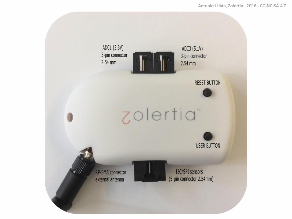
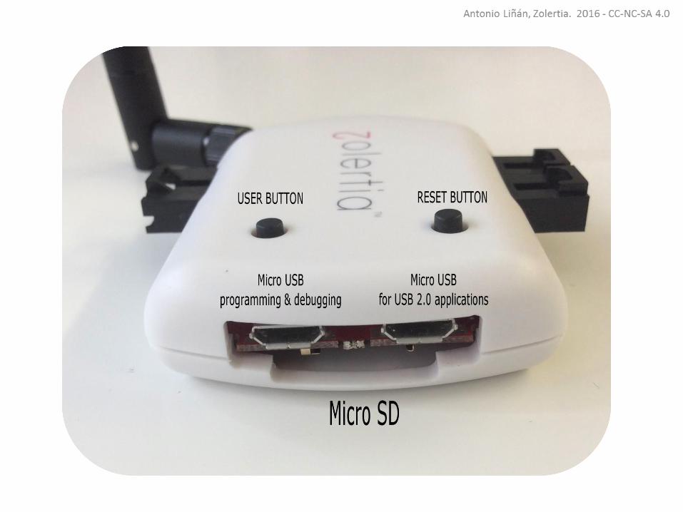
Zolertia RE-Mote

Zolertia RE-Mote (Zoul inside)
• ARM Cortex-M3, 32MHz, 32KB RAM, 512KB FLASH
• Double Radio: ISM 2.4GHz & 863-925MHz, IEEE 802.15.4-2006/e/g
• Hardware encryption engine and acceleration
• USB programing ready• Real-Time Clock and Calendar• Micro SD slot and RGB colors• Shutdown mode down to 150nA• USB 2.0 port for applications• Built-in LiPo battery charger to work with
energy harvesting and solar panels• On-board RF switch to use both radios over
the same RP-SMA connector• Pads to use an external 2.4GHz over U.Fl
connector, o solder a chip antenna

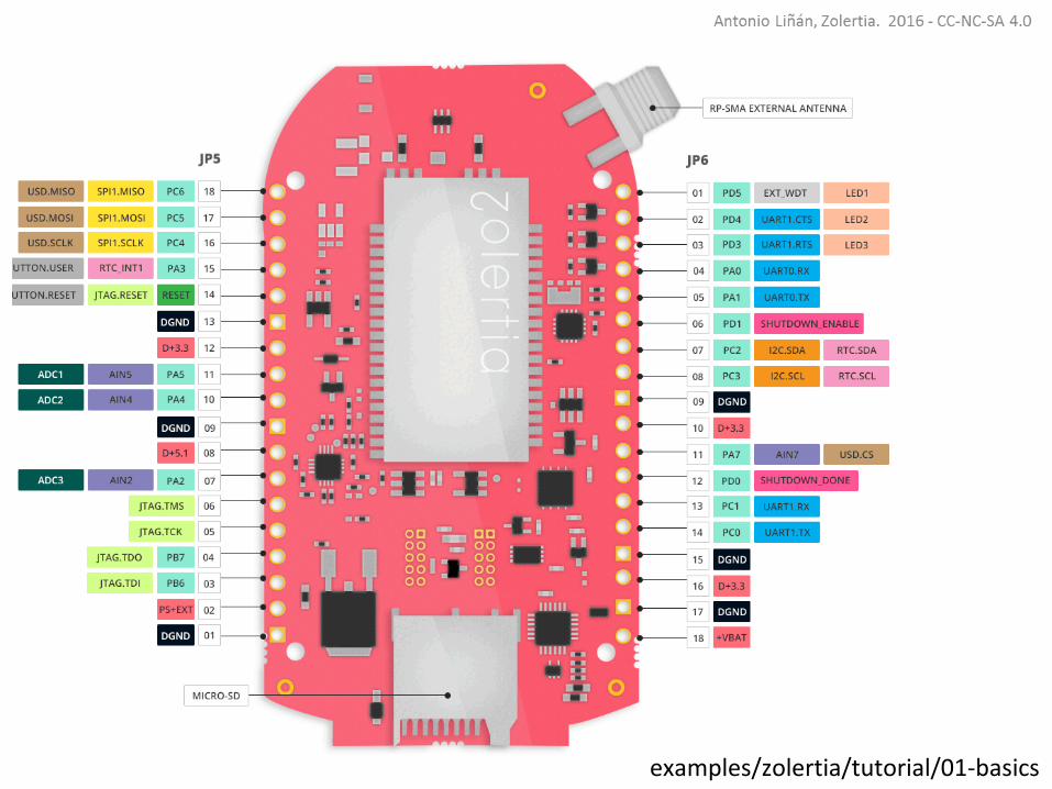
01-basics
examples/zolertia/tutorial/01-basics

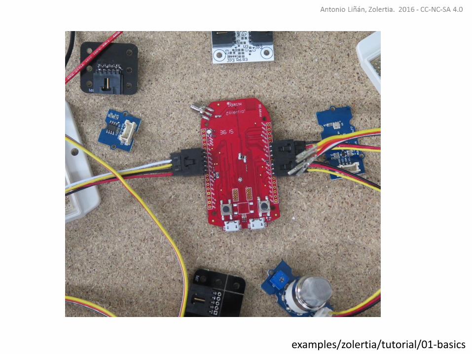
Sensors
A sensor is a transducer whose purpose is to sense or detect acharacteristic of its environment, providing a corresponding output,generally as an electrical or optical signal, related to the quantity ofthe measured variable.
examples/zolertia/tutorial/01-basics
examples/zolertia/tutorial/01-basics
Analogue sensors
Analogue sensors typically require being connected to an ADC(Analogue to Digital Converter) to translate the analogue(continuous) reading to an equivalent digital value in millivolts.
examples/zolertia/tutorial/01-basics

https://www.renesas.com/en-us.html examples/zolertia/tutorial/01-basics
The quality and resolution of the measure depends on both the ADCresolution (10-12 bits in the Z1 and RE-Mote) and the samplingfrequency.
As a rule of thumb, the sampling frequency must be at least twicethat of the phenomenon you are measuring.
i.e human speech (which may contain frequencies up to 8 kHz),sample at 16 kHz.
examples/zolertia/tutorial/01-basics

The ADC provides a count value (the analogue sensor quantized value). Depending on the sensor we may want to use the count value, or its equivalent voltage value.
𝑉𝑖𝑛 =𝐴𝐷𝐶 × 𝑉𝑟𝑒𝑓
𝐴𝐷𝐶𝑟𝑒𝑠=𝐴𝐷𝐶 × 3000 𝑚𝑉
(1 ≪ 12)=𝐴𝐷𝐶 𝑥 3000 𝑚𝑉
4096
The higher the resolution, higher the sampling time and the size of the value.
The accuracy and required resolution helps to choose the number of required bits to quantized
examples/zolertia/tutorial/01-basics

Normally the conversion formula (to obtain the actual measuringunits, i.e lux or celsius from the voltage value) are provided by thesensor manufacturer. In other cases, it is required to obtain bymeasuring and correlating with another calibrated source.
Depending on the accuracy on the sensor, we would either useactual units (i.e 1024 lux), or just characterize thresholds (i.e dark,bright). For the later, using a cheap sensor might be enough forthe application requirements.
examples/zolertia/tutorial/01-basics
examples/zolertia/tutorial/01-basics

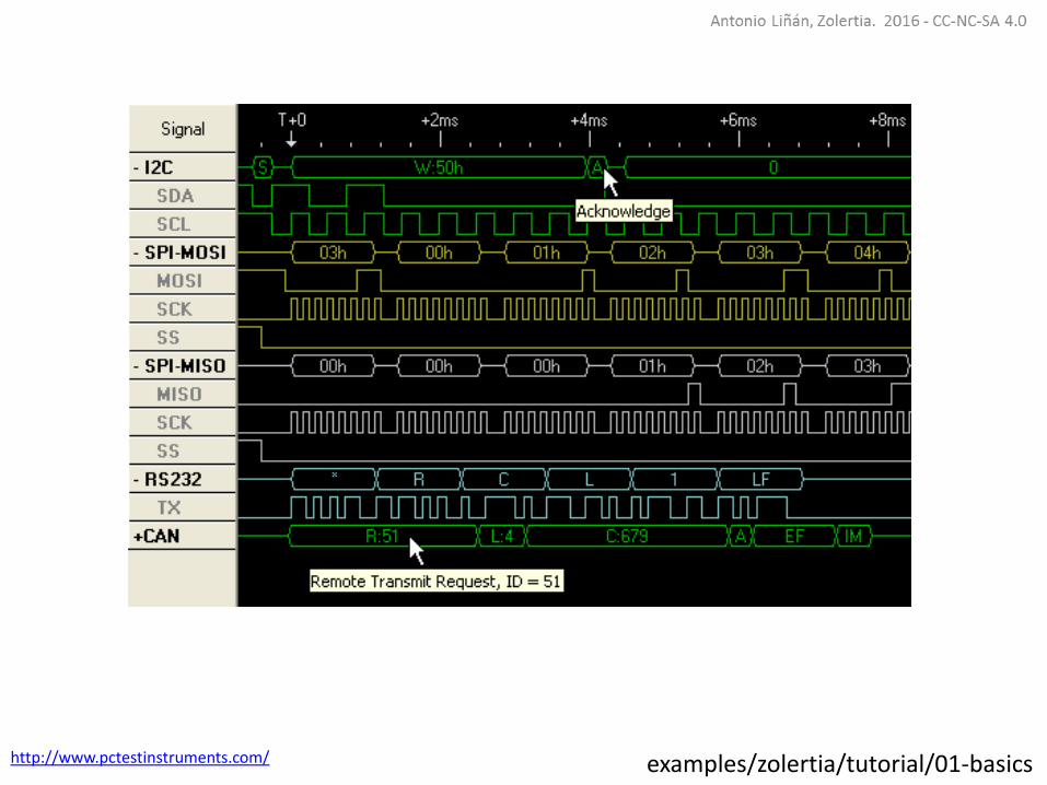
Digital sensors
A digital sensor is an electronic or electrochemical sensor,where data conversion and transmission are done digitally.
Digital sensors are normally interfaced over a digitalcommunication protocol such as I2C, SPI, 1-Wire, Serial ordepending on the manufacturer, a proprietary protocolnormally on a ticking clock.
examples/zolertia/tutorial/01-basics
http://www.pctestinstruments.com/ examples/zolertia/tutorial/01-basics
examples/zolertia/tutorial/01-basics
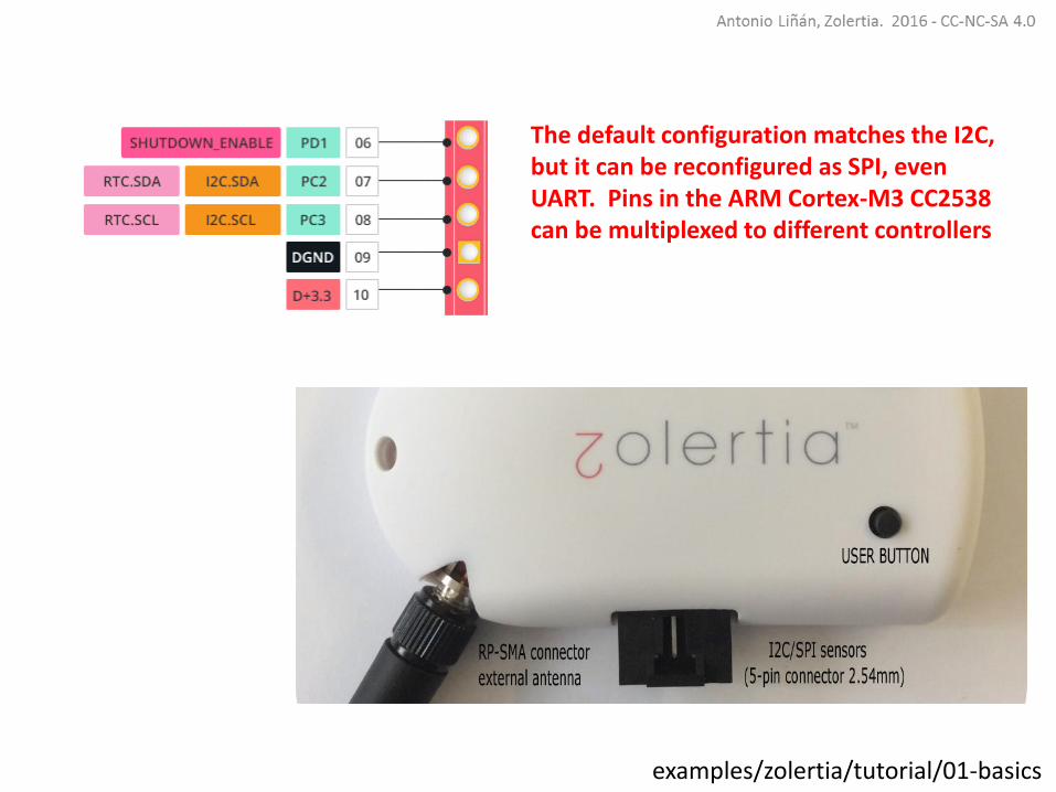
The default configuration matches the I2C, but it can be reconfigured as SPI, even UART. Pins in the ARM Cortex-M3 CC2538 can be multiplexed to different controllers

Digital sensors allow a more extended set of commands (turn on,turn off, configure interrupts, resolution, etc).
With a digital light sensor for example, you could set a thresholdvalue and let the sensor send an interrupt when reached, withoutthe need for continuous polling.
Remember to check the specificsensor information and data sheetfor more information.
examples/zolertia/tutorial/01-basics
Sensors in Contiki
Contiki defines a common API to implement and use bothsensors and actuators.
Normally platform-specific sensor implementations arelocated in the platform’s /dev folder.
Contiki has ADC, I2C, SPI and UART libraries, normally sensorand actuators implementations use these, so the portingeffort is greatly minimized.
examples/zolertia/tutorial/01-basics
core/lib/sensors.h
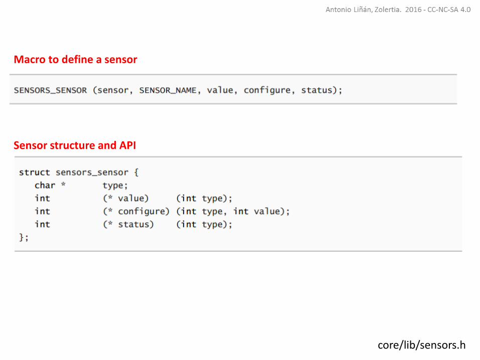
Macro to define a sensor
Sensor structure and API

platforms/zoul/dev/zoul-sensors.c
Default sensors constants and macros

platforms/zoul/dev/zoul-sensors.c
General structure to link the defined sensors
SENSORS structure expanded

General structure to link the defined sensors
examples/zolertia/tutorial/01-basics/06-adc.c
How to use the adc_zoul API:

General structure to link the defined sensors
examples/zolertia/tutorial/01-basics/06-adc.c
You can enable one or more sensors at the same time. Pins in the PORT A (PA) are used as ADC. The ADC can be configured using mask values

General structure to link the defined sensors
examples/zolertia/tutorial/01-basics/06-adc.c
The returned value is in milliVoltswith one extra precision digit, no need to convert from ADC raw count to voltage

platforms/zoul/remote/board.h

platforms/zoul/dev/adc-zoul.c

platforms/zoul/dev/adc-zoul.c
𝑉𝑎𝑑𝑐3(5𝑉) =𝑉𝑎𝑑𝑐3(3𝑉) ∗ 5
3
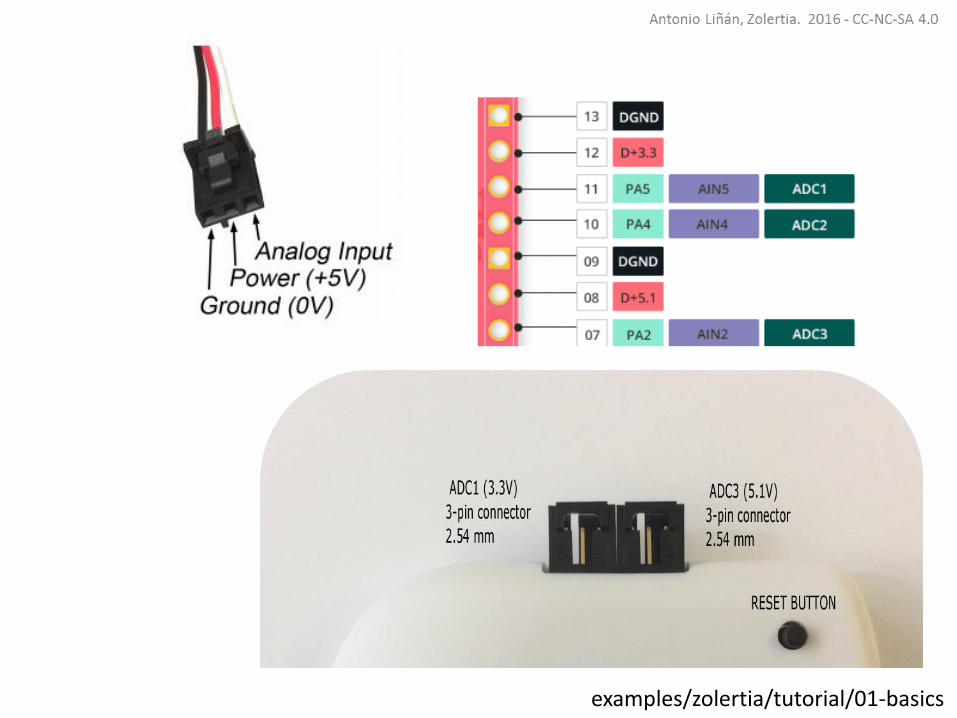
Note 3V and 5V analogue sensors can be connected, even if the RE-Mote works at 3V. The ADC3 channel has a voltage divider

examples/zolertia/tutorial/01-basics/06-adc.c
Connect an analogue sensor to the ADC1 connector (3V), and compile and program the 06-adc example:
make 06-adc.upload && make login
http://zolertia.io/product/sensors/analog-light-sensorhttp://www.seeedstudio.com/wiki/Grove_-_Light_Sensor
examples/zolertia/tutorial/01-basics/06-adc.c
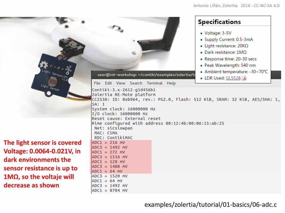
The light sensor is coveredVoltage: 0.0064-0.021V, in dark environments the sensor resistance is up to 1MΩ, so the voltaje willdecrease as shown
examples/zolertia/tutorial/01-basics/06-adc.c
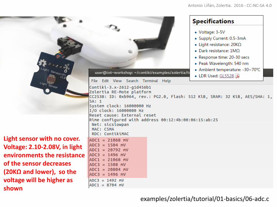
Light sensor with no cover.Voltage: 2.10-2.08V, in light environments the resistanceof the sensor decreases(20KΩ and lower), so the voltage will be higher as shown
examples/zolertia/tutorial/01-basics/06-adc.c
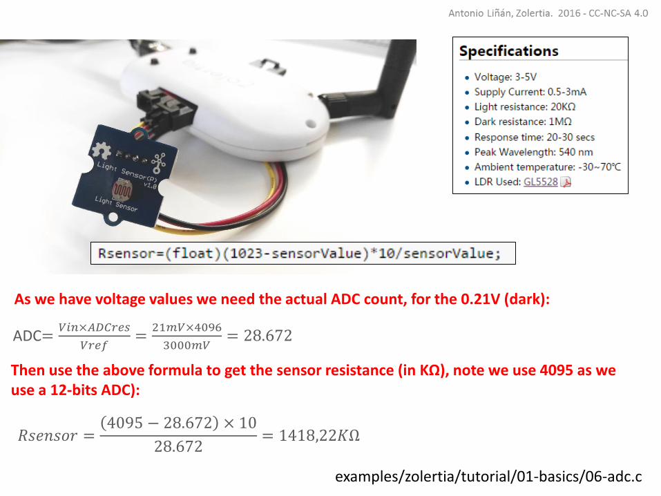
As we have voltage values we need the actual ADC count, for the 0.21V (dark):
ADC=𝑉𝑖𝑛×𝐴𝐷𝐶𝑟𝑒𝑠
𝑉𝑟𝑒𝑓=
21𝑚𝑉×4096
3000𝑚𝑉= 28.672
Then use the above formula to get the sensor resistance (in KΩ), note we use 4095 as we use a 12-bits ADC):
𝑅𝑠𝑒𝑛𝑠𝑜𝑟 =4095 − 28.672 × 10
28.672= 1418,22𝐾Ω
examples/zolertia/tutorial/01-basics/06-adc.chttps://forum.arduino.cc/index.php?topic=331679.0
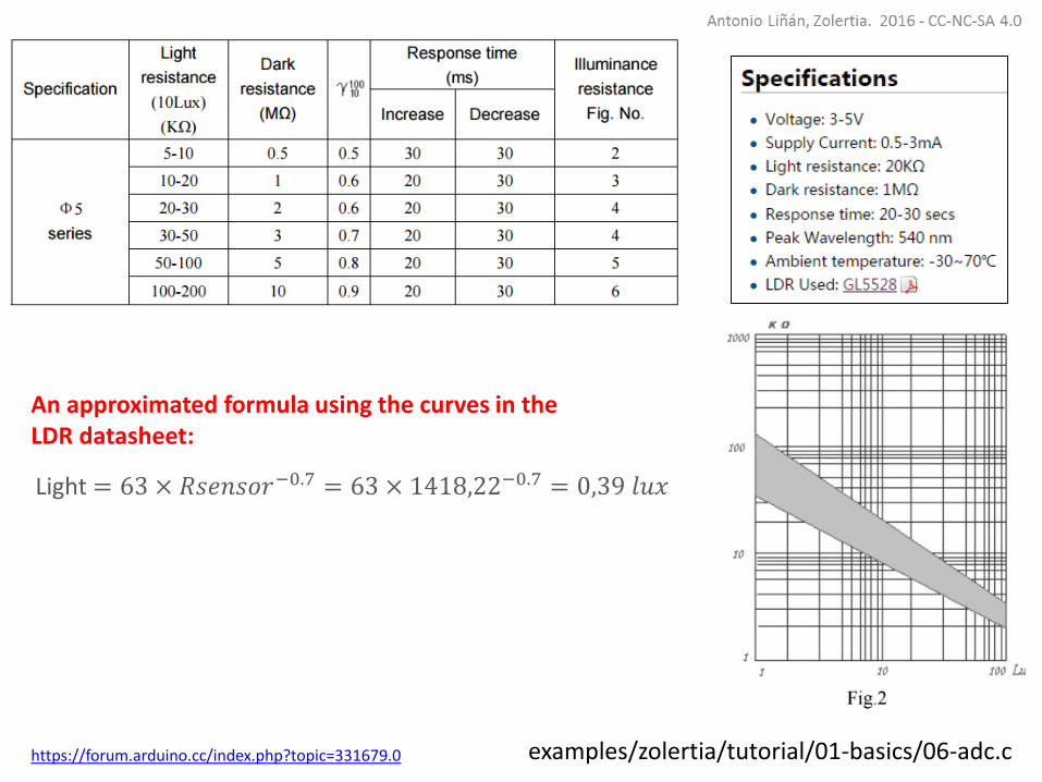
An approximated formula using the curves in the LDR datasheet:
Light = 63 × 𝑅𝑠𝑒𝑛𝑠𝑜𝑟−0.7 = 63 × 1418,22−0.7 = 0,39 𝑙𝑢𝑥

examples/zolertia/tutorial/01-basics/06-adc.chttps://forum.arduino.cc/index.php?topic=331679.0
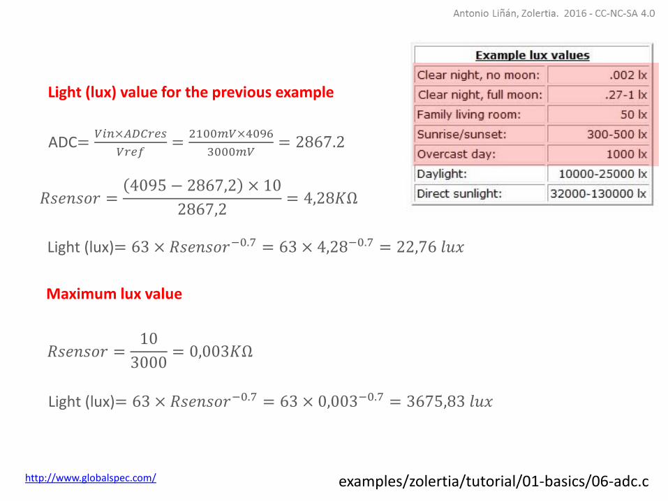
What is the lux value of the light environment (the one proportional to 2.10V) in previous slides?What would be the maximum lux value?
An approximated formula using the curves in the LDR datasheet:
Light = 63 × 𝑅𝑠𝑒𝑛𝑠𝑜𝑟−0.7 = 63 × 1418,22−0.7 = 0,39 𝑙𝑢𝑥
examples/zolertia/tutorial/01-basics/06-adc.c
𝑅𝑠𝑒𝑛𝑠𝑜𝑟 =4095 − 2867,2 × 10
2867,2= 4,28𝐾Ω
Light (lux)= 63 × 𝑅𝑠𝑒𝑛𝑠𝑜𝑟−0.7 = 63 × 4,28−0.7 = 22,76 𝑙𝑢𝑥
ADC=𝑉𝑖𝑛×𝐴𝐷𝐶𝑟𝑒𝑠
𝑉𝑟𝑒𝑓=
2100𝑚𝑉×4096
3000𝑚𝑉= 2867.2
𝑅𝑠𝑒𝑛𝑠𝑜𝑟 =10
3000= 0,003𝐾Ω
Light (lux)= 63 × 𝑅𝑠𝑒𝑛𝑠𝑜𝑟−0.7 = 63 × 0,003−0.7 = 3675,83 𝑙𝑢𝑥
Light (lux) value for the previous example
Maximum lux value
http://www.globalspec.com/

Exponential and logarithms are processing-expensiveoperations.
Instead of calculating the lux values, one could use thecorrelated voltage or ADC count value in the application (totrigger an alarm if the room is dark), or send over the radiothe ADC count and let the remote server/application to dothe math

examples/zolertia/tutorial/01-basics/05-onboard-sensors.c
The RE-Mote has two on-board sensors: voltage level and core temperature:
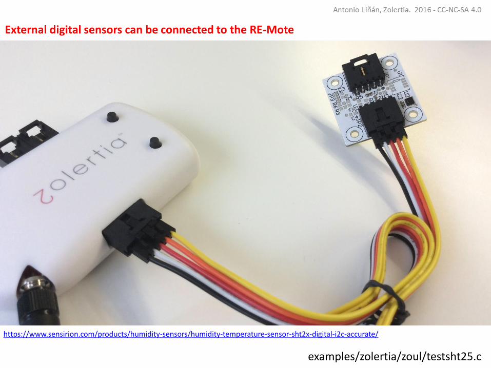
examples/zolertia/zoul/testsht25.c
External digital sensors can be connected to the RE-Mote
https://www.sensirion.com/products/humidity-sensors/humidity-temperature-sensor-sht2x-digital-i2c-accurate/

SHT21 temperature and humidity sensor (digital, I2C)
https://www.sensirion.com/products/humidity-sensors/humidity-temperature-sensor-sht2x-digital-i2c-accurate/
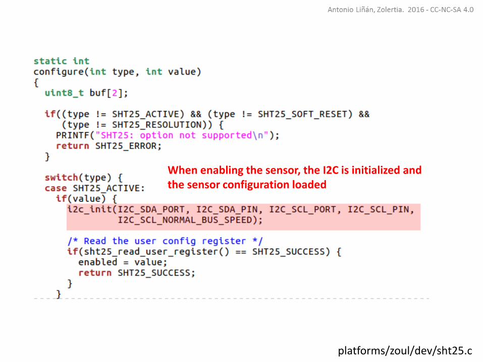
platforms/zoul/dev/sht25.c

examples/zolertia/zoul/Makefile
Add the sensor’s library to the application’s Makefile

examples/zolertia/zoul/test-sht25.c
platforms/zoul/dev/sht25.c
When enabling the sensor, the I2C is initialized and the sensor configuration loaded
platforms/zoul/dev/sht25.c
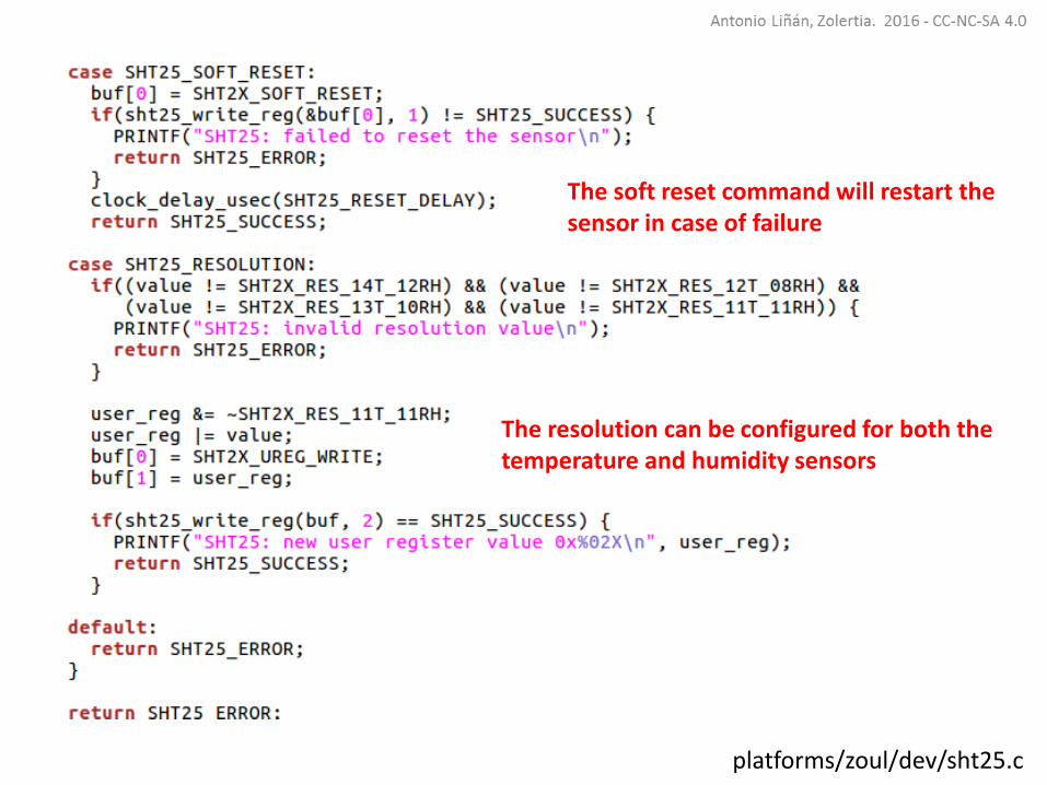
The soft reset command will restart thesensor in case of failure
The resolution can be configured for both the temperature and humidity sensors

platforms/zoul/dev/sht25.c
The I2C API is used to read and write to the sensor’s registers
The sensor’s values are converted into readable units: Celsius and Relative Humidity, with 2 precision digits

Actuators
An actuator is a device that allow us to interact with the physicalworld, and change the state of a given variable. A light switch turns alight bulb on and off, an electrovalve can control the flow of water, anelectronic lock can open or shut a door
examples/zolertia/tutorial/01-basics

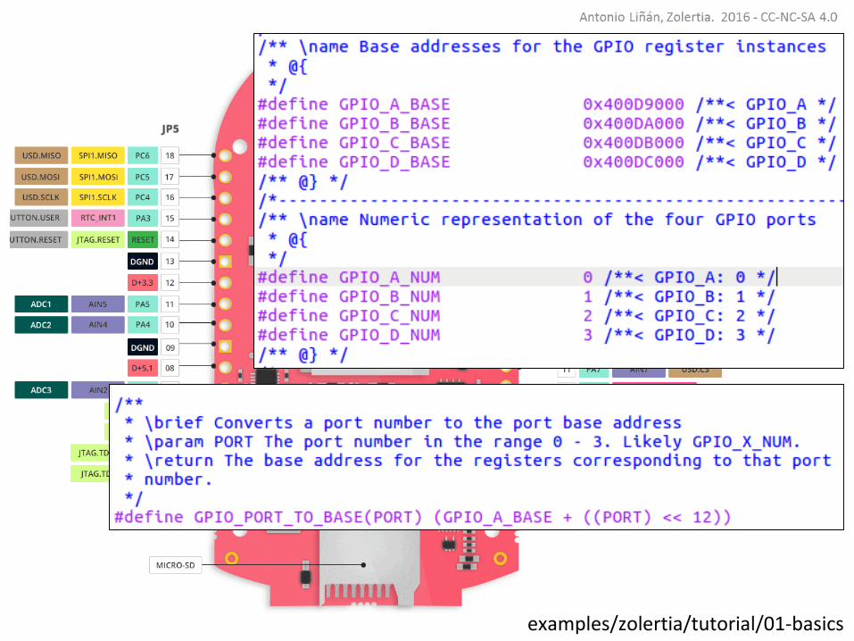
General Input/Output Pins (GPIO)
The General input/output pins are generic pins used either as input oroutput (0-3.3V), useful in case you need to actuate on something, orread the digital voltage level as high/low (3.3V or 0V).
Normally the electrovalves, relays, switchs are bi-state, so a GPIO pin canbe used to control.
The LEDs are driven by GPIOs configured as output, changing its valuefrom high/low turns the LEDs on/off (depending if used a pull-up or pull-down resistors).
The user button previously shown is a GPIO configured as input, whenpressed its value changed, and its status is read by the MCU.
examples/zolertia/tutorial/01-basics
examples/zolertia/tutorial/01-basics

examples/zolertia/tutorial/01-basics
Each PORT has 8 PINs, numbered from 0-7PA5 then is the PIN number 6 in PORT A
examples/zolertia/tutorial/01-basics
examples/zolertia/tutorial/01-basics
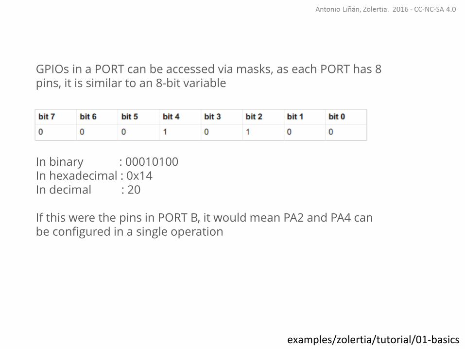
GPIOs in a PORT can be accessed via masks, as each PORT has 8 pins, it is similar to an 8-bit variable
In binary : 00010100In hexadecimal : 0x14In decimal : 20
If this were the pins in PORT B, it would mean PA2 and PA4 can be configured in a single operation

examples/zolertia/tutorial/01-basics
PIN 3 mask value would be (1 << 3), the equivalent to 8
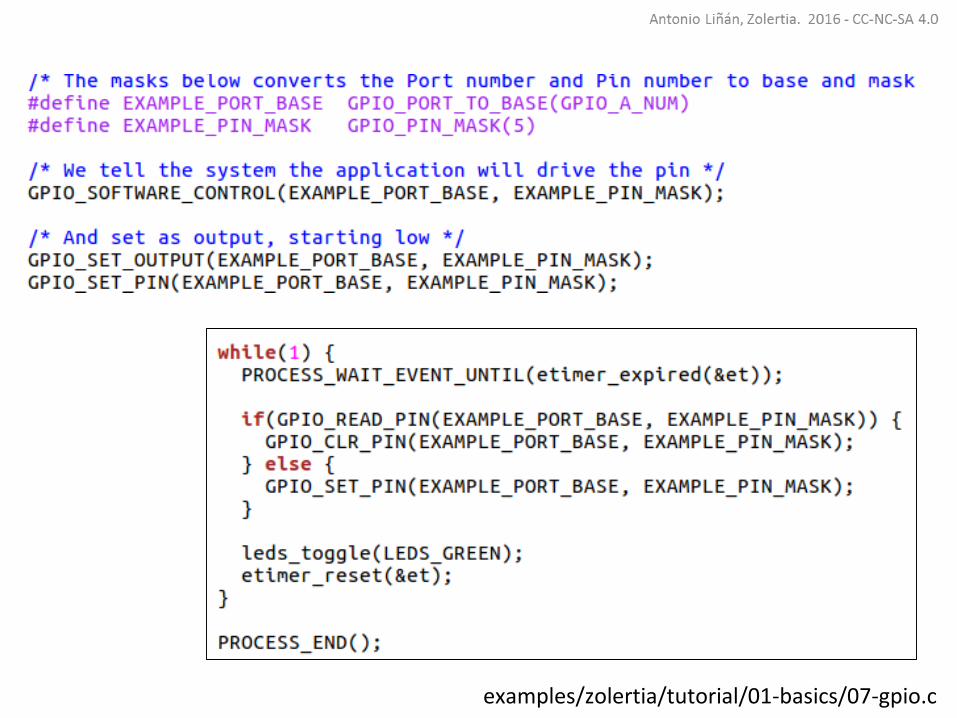
examples/zolertia/tutorial/01-basics/07-gpio.c

examples/zolertia/tutorial/01-basics/07-gpio.c
Change the value of the PIN in theexample, and toggle the LED3 (see in theprevious slides which PORT/PIN valuescorresponds to it)
If available, use a multimeter to measurethe voltage values in the pins when highand low.
If available, connect a relay and try toturn on and off a lamp
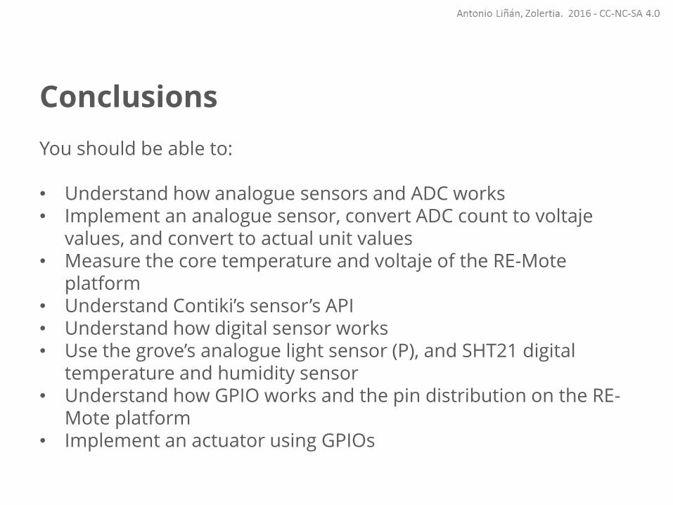
Conclusions
You should be able to:
• Understand how analogue sensors and ADC works• Implement an analogue sensor, convert ADC count to voltaje
values, and convert to actual unit values• Measure the core temperature and voltaje of the RE-Mote
platform• Understand Contiki’s sensor’s API• Understand how digital sensor works• Use the grove’s analogue light sensor (P), and SHT21 digital
temperature and humidity sensor• Understand how GPIO works and the pin distribution on the RE-
Mote platform• Implement an actuator using GPIOs

Antonio Liñán Colina
Twitter: @4Li6NaN
LinkedIn: Antonio Liñan Colina
github.com/alignan
hackster.io/alinan
[email protected]@gmail.com