contents sheets/avago pdfs/hdjd-jd07_ug.pdfselected from internal or external power supply. using...
TRANSCRIPT

HDJD-JD07Development Kit
User Guide
Contents
Introduction . . . . . . . . . . . . . . . . . . . . . . . . . . . . . . . . . . . . . . . . . . . . . . . . . . . . . . . . . . . . . . . . . . . . . . . . . . . . . . . . . . . . . . . . . . . . . . . . . . . . . . . . . . . . . . . . . . . . . . . . . . 1
Startup . . . . . . . . . . . . . . . . . . . . . . . . . . . . . . . . . . . . . . . . . . . . . . . . . . . . . . . . . . . . . . . . . . . . . . . . . . . . . . . . . . . . . . . . . . . . . . . . . . . . . . . . . . . . . . . . . . . . . . . . . . . . . . . . 2
Hardware Design . . . . . . . . . . . . . . . . . . . . . . . . . . . . . . . . . . . . . . . . . . . . . . . . . . . . . . . . . . . . . . . . . . . . . . . . . . . . . . . . . . . . . . . . . . . . . . . . . . . . . . . . . . . . . . . . . . . . . 3
Hardware Setup & Configuration . . . . . . . . . . . . . . . . . . . . . . . . . . . . . . . . . . . . . . . . . . . . . . . . . . . . . . . . . . . . . . . . . . . . . . . . . . . . . . . . . . . . . . . . . . . . . . . . . . 8
PC Software Guide . . . . . . . . . . . . . . . . . . . . . . . . . . . . . . . . . . . . . . . . . . . . . . . . . . . . . . . . . . . . . . . . . . . . . . . . . . . . . . . . . . . . . . . . . . . . . . . . . . . . . . . . . . . . . . . . . .11
WARNING: This product is non-RoHS compliant.

Copyright © 2007 Avago Technologies, Inc. All Rights Reserved.
Avago grants you (“Licensee”) a non-exclusive, royalty free, license to use this software in binary code form.
Disclaimer, Warning & CreditsDisclaimerTO THE EXTENT ALLOWED BY LOCAL LAW, THIS SOFTWARE IS PROVIDED TO YOU ‘AS IS’ WITHOUT WAR-RANTIES OR CONDITIONS OF ANY KIND, WHETHER ORAL OR WRITTEN, EXPRESS OR IMPLIED. AVAGO SPECIFICALLY DISCLAIMS ANY IMPLIED WARRANTIES OR CONDITIONS OF MERCHANTABILITY, SATISFACTORY QUALITY, NON-IN-FRINGEMENT AND FITNESS FOR A PARTICULAR PURPOSE. SOME JURISDICTIONS DO NOT ALLOW EXCLUSIONS OF IMPLIED WARRANTIES OR CONDITIONS, SO THE ABOVE EXCLUSION MAY NOT APPLY TO YOU. YOU MAY HAVE OTHER RIGHTS THAT VARY ACCORDING TO LOCAL LAW.
TO THE EXTENT ALLOWED BY LOCAL LAW, IN NO EVENT WILL AVAGO OR ITS SUBSIDIARIES, AFFILIATES OR SUPPLIERS BE LIABLE FOR DIRECT, SPECIAL, INCIDEN-TAL, CONSEQUENTIAL OR OTHER DAMAGES (INCLUDING LOST PROFIT, LOST DATA, OR DOWNTIME COSTS), ARISING OUT OF THE USE, INABILITY TO USE, OR THE RESULTS OF USE OF THE SOFTWARE, WHETHER BASED IN WARRANTY, CONTRACT, TORT OR OTHER LEGAL THEORY, AND WHETHER OR NOT ADVISED OF THE POSSIBILITY OF SUCH DAMAGES.
YOUR USE OF THE SOFTWARE IS ENTIRELY AT YOUR OWN RISK. SOME JURISDICTIONS DO NOT ALLOW THE EXCLUSION OR LIMITATION OF LIABILITY FOR DAMAGES, SO THE ABOVE LIMITATION MAY NOT APPLY TO YOU. THIS DEVELOPMENT KIT IS A FAMILIARIZATION KIT AND IT IS FOR EVALUATION PURPOSE ONLY. IT IS NOT SUBJECT TO RELIABILITY ASSESSMENT AND AVAGO IS NOT LIABLE.
WarningDO NOT CONNECT OR DISCONNECT ANYTHING WHILE THE HDJD-JD07 DEVELOPMENT KIT OR THE PC IS SWITCHED ON!!! Doing so anyway may damage your PC and/or the HDJD-JD07 Development Kit permanently. Make sure power is off while interfacing with the Control-ler Board. DO NOT & never switch off power from control-ler board while program is running.
CreditsCIE xy chart – Prof. Geoff Hoffman (http://www.fhoemden.de/~hoffmann/)
Windows™ is a trademark of Microsoft Corporation.
I2C is a trademark of Royal Philips Electronics.
Other trademarks are the property of their respective owners and are hereby acknowledged.

1
IntroductionAvago Technologies has introduced a new smallest digital color sensor ADJD-S311-CR999, with a package size of 2.2x2.2x0.76[mm]. With a four-channel Red (R), Green (G), Blue (B) and Clear (C) color filters coated over the photo-diode array and integrated analog to digital converter (ADC), the sensor converts light to digital outputs. This device is designed to cater for wide dynamic range of illumination level and is ideal for applications like portable or mobile devices, which demand higher integration, smaller size and low power consumption. Sensitivity control is performed by the serial interface and can be optimized individually for the different color channel. The sensor can also be used in conjunction with a white LED for reflective color management.
The color sensor development kit, HDJD-JD07 is used as a guide to the application of ADJD-S311-CR999 besides demonstrating the principle of color sensing. The color sensor development kit can be used for both transmis-sive and reflective sensing.
Some of the HDJD-JD07 features include:
• Easily interface with PC via standard USB port which is compatible with most IBM PC.
• User-friendly software with displays of output digital readings, conversion to standard color format, data-log and CIE color chart features.
• Color sensor controller board consists of 2-wire serial interface to USB converter module, power supply module, LED constant current module and digital color sensor control module.
Avago’s HDJD-JD07 serves as exemplary circuit applica-tion for composing other simple reflective and trans-missive color detection system with ADJD-S311-CR999. This development kit will be the reference design for designers and users that needs to perform quick evalua-tion using the digital color sensor.
This user guide will discuss some features and advantages of ADJD-S311-CR999, the basics of reflective and trans-missive sensing, the hardware construction of HDJD-JD07 development kit, how to setup and configure the kit and description of the GUI.

2
StartupIncluded in delivery
Standard Avago HDJD-JD07 includes the following components:
• One sensor module
• One Controller Board (CB)
• One USB cable
• One CD with installation software
Figure 1. Sensor Module Figure 2. Digital Color Sensor Controller Board
Figure 3. USB cable Figure 4. CD with installation software

3
Hardware Design
HDJD-JD07 Block Diagram
2.6V
Jumper
PIC18F2455
PWMD+D-
Micro-controller
USBConnector
5V 2.6V
White LED
SCLSDA
Color sensor
Regulator+5V
Display/GUI Unit +Process ing
Main Board with USB interface
Color Sensor ModuleMounted on PCB with
Plastic Case
CLK_ INXRST
SLEEP
SCLSDA
AVDD DVDD AVSS DVSS
12V
Po weradapter
Linearregulator,LM7805
5V
Adjustable regulator, LM317Jumper
5V
Jumper
P82B96
DualBidirectionalBus Buffer
External CLK
External Supply2.6V
R232k7
Hardware Features:
• The development kit consists of a main board and a sensor board which is interchangeable and is connected using pin connector and ribbon wire.
• The power supply for the color sensors can be selected from internal or external power supply. Using external supply will ease the measurement of power consumption of the color sensor using a power meter.
• The color sensors can have the option of using internal or external clock.
• The LED and the sensor can be controlled independently. There is a switch to turn on/off the LED and a trimmer to change the LED current. The
LED can also be controlled by PWM or the sensor’s SLEEP pin.
• The power supply could be chosen from the AC adaptor or the USB.
• There are switches at the main board to reset the color sensor and to control the sleep mode.
• Interface with PC via standard USB port.

�
Figure 5. ADJD-S311 Spectral Response
Color Sensor Module
The color sensor module comprises an illuminant, digital color sensor and the mechanical block. The Avago white LED (HSMW-C191) is used as the illuminant/light source and digital color sensor (ADJD-S311-CR999) as the detector. The mechanical block which is made with delrin, will not only acts as the casing but also features an alignment gauge for maintaining an optimum gap between sensor and the targeted surface. The recom-mended distance of the sensor from the surface is 2.5 to 4mm for reflective sensing.
The ADJD-S311-CR999 is a cost effective, CMOS digital output RGB+C color sensor in miniature surface-mount package with a mere size of 2.2x2.2x0.76mm. The color sensor’s basic architecture comprises integrated RGB+C filters built on a uniformly distributed photodiode array, a logic control core, and a gain selector with an ADC that supports digital communication. The uniform RGB filters and photodiode array minimize the effect of light-gradients caused by optical misalignment and irregular-ity of surfaces.
The output allows direct interface to micro-controller or other logic control for further signal processing without the need of any additional components. With its wide sensing range, the sensor can be used for many appli-cations with different light levels, simply by adjusting the gain setting. Sensitivity control is performed by the serial interface and can be optimized individually for the different color channel. The integrated ADC helps to remove unwanted noise caused by analog signal pre-conditioning. Additional features include a selectable sleep mode to minimize current consumption when the sensor is not in use. For more details of ADJD-S311-CR999 specifications, please refer to the datasheet which can be download at www.avagotech.com.
0
0.2
0.4
0.6
0.8
1
400
420
440
460
480
500
520
540
560
580
600
620
640
660
680
700
Wavelength (nm)
Rel
ativ
e se
nsi
tivi
ty

�
Reflective Color Sensing Theory of OperationBy definition of reflective sensing, the color sensor detects light reflected from a surface or an object. The sensor module is designed in such a way that both the light source and the color sensor are placed closed to the target surface/object. Light coming from the LED is bounced off a surface/object and measured by the sensor. For a given light source, the color of light reflected off a surface/object is a function of the surface/object color. For example, white light incident onto a red surface is reflected as red. Since any color is uniquely represented by its R, G and B components, the sensor module effec-tively measures the color of a surface/object by convert-ing the R, G and B components of the reflected light to digital value. In addition, given that the outputs increase linearly with the intensity of reflected light, the sensor also measures the reflectivity of a surface/ object where the clear channel could be use for this purpose.
Transmissive Color Sensing Theory of OperationBy transmissive, it means the application kit is placed facing the light source being measured. The filter-coated photodiode array of the color sensor converts the R, G, B components of light falling on it into photocurrent, which is then converted into digital values for each of the primary component. Given that any colored light is uniquely represented by the ratio of the primary colors, the color sensor provides a definite manner of measuring color. In addition, the sensor is also responsive to light intensity where its outputs increase linearly with increasing light intensity. To measure the brightness of the light source without the need to know the color, the clear channel can be used.
For a given light source, the application kit can also be used to determine the color of transparent medium through which the light is passed before reaching the sensor. For example, the medium could be glass, plastic or liquid. To use HDJD-JD07 in transmissive mode, simply turn off the white LED on the sensor module.
Figure 6. For a given light source, the color of reflected depends on surface/ object color
Dig
ital v
alue
s
Dig
ital v
alue
s
Figure 7. R, G, B outputs of the sensor is determined by color of light falling on the sensor
Figure 8. Apply color sensor on media such as color filter, gas or liquid

�
Digital Color Sensor Controller BoardThe digital color sensor controller board consists of the following modules:(i) 2-wire Serial Interface to USB Converter Module
(ii) Power Supply Module
(iii) LED Constant Current Module
(iv) Digital Color Sensor Control Module
2-wire Serial Interface to USB Converter ModuleThis module converts the 2-wire serial interface from the digital color sensor to USB protocol that can be easily interface with the PC. The main components of this module are dual bidirectional bus buffer, P82B96 and USB microcontroller, PIC18F2455. The P82B96 interface the two different logic level from the microcontroller (5V) and digital color sensor (2.6V) while the microcontroller interface the 2 wire serial to USB.
Figure 9. 2-wire serial interface to USB Converter Block Diagram
SC L, SDA@5V
Digital Co lorSensorADJD-S311
SC L, S [email protected]
Dual BidirectionalBus BufferP82B96
USBMicroco ntrollerPIC18F2455
To PC via USB cable
Power Supply Module The power supply module taps power from the adapter and provides regulated voltage 5V for the microcon-troller and 2.6V for the digital color sensor.
Figure 10. Power Module Block Diagram
5V
Poweradapter 9V – 20V
Linear regulator,LM7805
Adjustableregulator, LM317
2.6V
USB 5V

�
LED Constant Current ModuleThis module provides constant current to the white LED using regulator LP38691-ADJ. The current can be adjusted from 2-30mA, however, typical current of 5mA is recommended. The LED current can be measured by measuring the voltage across R20 using test pin TP1/TP2. The current can then be calculated with I = V/10. (Note: The max DC current for the white LED is recommended at 10mA).
Figure 11. LED Constant Current Circuit
Figure 12. Digital Color Sensor Control Module Block Diagram
J9CLK _IN SLEEP
Digital Co lorSensor
ADJD-S311
XRST
+2.6V
Digital Color Sensor Control ModuleConsist of reset, external clock and sleep circuit for the digital color sensor. The clock signal from the signal generator or other oscillator can be connected to pin header J9.
8
Hardware Setup and ConfigurationSetup:
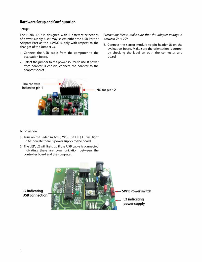
The HDJD-JD07 is designed with 2 different selections of power supply. User may select either the USB Port or Adapter Port as the +5VDC supply with respect to the changes of the Jumper J3.
1. Connect the USB cable from the computer to the evaluation board.
2. Select the jumper to the power source to use. If power from adapter is chosen, connect the adapter to the adapter socket.
To power on:
1. Turn on the slider switch (SW1). The LED, L3 will light up to indicate there is power supply to the board.
2. The LED, L2 will light up if the USB cable is connected indicating there are communication between the controller board and the computer.
Precaution: Please make sure that the adapter voltage is between 9V to 20V.
3. Connect the sensor module to pin header J8 on the evaluation board. Make sure the orientation is correct by checking the label on both the connector and board.

�
Other functions:
1. Selecting internal or external power supply for the color sensor.
Use J1 to select the source 2.6V for the color sensor. If external 2.6V is chosen, connect the supply to TB1. The external supply is to ease the measurement of sensor’s power consumption.
2. Selecting White LED control
The white LED can be turn on/off using 3 methods which is PWM from microcontroller, Sleep pin of color sensor during external clock mode and Jumper J6. Use jumper J7 to select either use PWM or Sleep pin, leaving the J6 disconnected. Connecting J6 will turn on the White LED using constant current bypassing the PWM and Sleep selection.
The LED can be dim by changing the current by adjusting the variable resistor VR2. The LED current can be measured by measuring the voltage across R20 using test pin TP1/TP2. The current can then be calculated with I = V/10. (Note: The max current for the white LED is recommended at 10mA). Another way to change the brightness of the LED is by changing the PWM duty cycle from the software GUI although 100% duty cycle/constant current is recommended for sensor operation.
3. Sleep function
Connect jumper J4 to put the sensor into sleep mode to minimize power consumption when sensor not in use.
4. Color Sensor reset
Push SW2 to reset the color sensor.
5. External clock
The sensor is operating with internal clock at typical frequency of 26MHz. To use external clock connect the clock signal to pin 1 of J9 (the pin located closer to J8) while pin 2 of J9 is the reference ground.

10
Basic Description of Evaluation Board
SW1 : Power OnSwitch
ON
OFF
J3: Power sourceselection
Adapter
USB
TB1: Externalpower supplyfor sensor
J1: Selection ofinternal or external2.6V for sens or
J7: White LEDcontrol se lection
VR2: Adjustingwhite LED current
J4: Sleep modeif connected
J6: Connect t o turn onwhite LED and bypassPWM/Sleep control.
SW2 : Press toreset color sensor
ConnectUSB here
J9: Connect ex tclock here.GN D XCLK

11
PC Software GuideAvago’s HDJD-JD07 Digital Color Sensor Development Kit software is developed to be a tool for user to acquire knowledge on how to use ADJD-S311-CR999 and how color sensor can be applied. The interactive graphical user interface has made the software to be user friendly and easy to use. The same software can be used for both reflective and transmissive mode.
Software Installation
To install the software to the PC:
1. Insert the installation CD to the CD-ROM drive
2. Click Start, then click Run
3. Type D:\setup and press Enter.
IMPORTANT: Use the appropriate drive letter in the above command to install the software. CD-ROMs are commonly “D:”.
The installation program will guide you through the software installation.
Note: If any text box appeared noting that the current system file has a newer version, just select ‘Ignore’ button.
Software GUI Guide
1. Configuration and control registers
These are the internal registers that configure the color sensor and control its functions.
2. Sensor setup registers
These boxes contain the sensor gain settings that adjust the sensitivity of the sensor. The user can key in data into these boxes to manually change the gain or can use the white calibration feature to generate the optimum gain value.
3. Sensor and offset registers
The sensor registers store the digitized readings of the color sensor and the offset register store the offset value of the color sensor.
4. Console
The console is a general-purpose method to write to and read from the sensor. The user enters just the register address to read. To write, enter both the address and data.
5. Color Conversion
Display the sensor readings in XYZ tristimulus values, CIE Yxy color space and L*a*b* Color space. The XYZ, Yxy and Lab value will only be shown if the checkbox for “Activate Color Chart/Conversion” is checked after some settings are made.
6. Comms
The user needs to check the communication between the software and the board before using the software by pressing the “test” button. Red means the communications test failed. Green means it passed.
Software Features:
• Compatible with Windows XP and 2000.
• Developed with Visual Basic.
• List of color sensor registers for user references.
• Display of R, G, B and C readings.
• Manual gain selection.
• White calibration (Auto-gain feature).
• Color Conversion to standard color space.
• Data-log features to save the R,G,B and C readings to text and excel files.
• CIE xy chart to display the color measured.
• PWM Window to turn on/off and control the bright-ness of white LED.

12
Writing and Reading Registers
Check means put a tick next to the register bit and press the write button. A check means logic 1 written to the register bit. Nothing is written to the device until the write button is pressed. For example, to grab sensor readings, put a tick for GSSR and press the write button.
If the read button is pressed, the register for that read button is read. A logic 1 is represented by a tick next to the register but. E.g. in the picture, the read button for the CONFIG register was pressed and the EXTCLK bit has a tick to indicate that the device is using external clock.
To change the sensor capacitance or integration time, change the value in the textbox and press the write button.
The update registers button can be used to read all the registers at once, including sensor setup, offset and sensor output registers.
Brief description of the register bits. Refer to datasheet for details.
GOFS Check to grab offset reading.
GSSR Check to grab sensor reading.
EXTCLK Check to use external clock.
SLEEP Check to put sensor in sleep mode when using external clock.
TOFS If checked, the sensor output will auto-matically deduct the offset before stored in sensor output register.
LED_EN Check to enable the LED control using Sleep pin when using external clock.
LED_ON Check to turn on the LED.
CAP_RED Enter 0 to 15 to choose number of red channel capacitor.
CAP_GREEN Enter 0 to 15 to choose number of green channel capacitor.
CAP_BLUE Enter 0 to 15 to choose number of blue channel capacitor.
CAP_CLEAR Enter 0 to 15 to choose number of clear channel capacitor.
INT_RED Enter 0 to 4095 to choose red channel inte-gration time slot.
INT_GREEN Enter 0 to 4095 to choose green channel integration time slot.
INT_BLUE Enter 0 to 4095 to choose blue channel inte-gration time slot.
INT_CLEAR Enter 0 to 4095 to choose clear channel integration time slot.

13
File Menu
File>…
The user can save the current state of the GUI i.e. the check boxes and data in the text boxes into a configura-tion file. This file can be loaded in the next session and all previous user data will be re-loaded.
File>Open Loads a configuration file
File>Save As… Saves the current configuration as *.cfg
File>Exit Exits the software
Tools>…
In Tools menu, there are several windows that can be accessed:
Tools>CIE xy chart Opens CIE xy Chart window
Tools>White Calibration Opens White Calibration window

1�
Easy Access
Save the current setting to *.cfg file.
Load previous saved *.cfg file to the color sensor.
Open the White Calibration window, refer the window below for details.
Obtain the sensor output readings.
Open the PWM window to control white LED, refer PWM window for details.
Press the Update button to write the PWM duty cycle stated at the textbox to the microcontroller. The duty cycle may be change although it is recommended to use 100% for reflective sensing applications.
To turn off the LED, press Off button.
Steps for white calibration:
1. Key in the target value of Red, Green, Blue and Clear channel.
2. Select the capacitance value from 0 to 15.
3. Select the maximum integration time the program will sweep to get target value (max 4095).
4. Click on the White Calibration button while pointing the sensor to the reference white surface (Gretag Macbeth Chart white patch).
5. The TINT (integration time) will changed and the sensor reading will be displayed. This is the integration time to get the target value and is updated to the sensor registers.

1�
CIE xy chart
The CIE xy chart can be accessed in the following 2 ways:
1. Click on CIE xy Chart button at features section at the main GUI.
2. Click menu Tools -> CIE xy Chart.
To view the CIE xy chart real time, user had to activate the color conversion. Then a circle will appear showing the color measured by the color sensor at the CIE xy chart.

1�
Numerical Data Log
With this numerical data log feature, the user can identify and keep track the consistency and repeatability of the color being scanned. The user can also save the data so that it can easily be retrieved later. The data log can be access by clicking on ‘Data Log’ button at features section at the main GUI.
Buttons function at Data log windows:
Get data: Transfer the digital readings measured and displayed at the main GUI to the data log windows.
SaveAs : Save file as several different types of format (e.g. RTF, Text Files or Excel Files).
Clear: Clear the display screen of data log windows.
Exit: Close the data log window.

Activation of Color Conversion
The following is the step by step procedure to activate the color chart and color conversion. To make sure that the conversion is correct, the procedure should be strictly followed.
1. Perform white calibration with target value of 1000 for all channels using white patch of GretagMcbeth color chart.
2. After white calibration, check the Activate Color Conversion checkbox. A message box will appear, click Yes to confirm all procedure correctly done.
3. The color conversion and real time CIE xy chart is now activated. Click Grab Sensor button to measure color as usual but now the sensor reading will also be converted to other standard color space and displayed at the color conversion frame.
4. Once color conversion is activated, the gain setting (sensor setup) is disabled until the Color Conversion is unchecked.
For product information and a complete list of distributors, please go to our web site: www.avagotech.com
Avago, Avago Technologies, and the A logo are trademarks of Avago Technologies, Limited in the United States and other countries .Data subject to change . Copyright © 200� Avago Technologies Limited . All rights reserved . AV02-03�8EN - July �, 200�