bayanbox.irbayanbox.ir/view/1169227936913776932/powermill-9-five-axis... · powermill contents...
TRANSCRIPT

Important Notice
This document is supplied as part of a Delcam Training Course. It is not intended to be
distance-learning material: rather as an aid for Tutors when presenting material to course
delegates and as a subsequent aid memoir to those delegates.
Delcam does not accept responsibility for any personal belongings / valuables whilst on the
premises. Delegates are advised to keep their belongings on their person at all times.
Delcam plc. has no control over the use of the software described in this document and
cannot accept any responsibility for any loss or damage howsoever caused as a result of using
the software. Users are advised that all results from the software are checked by a competent
person in accordance with good quality control procedures.
The software described in this document is furnished under a license agreement and may be
used only in accordance with the terms of such license.
Copyright 2008 – Delcam plc. All rights reserved
Training Centre Customer Support
Tel: 0121 683 1050 Tel: 0121 683 1010
Fax 0121 7665511 Fax: 0121 7665542

PowerMILL Contents
Issue PMILL 9 1
PowerMILL 9 Five Axis Contents
Chapters Page Number
Day 1
1. 3+2 Axis Machining and Driling 1.1 - 1.26
2. Five Axis Tool Alignment 2.1 - 2.26
3. Surface Projection Finishing 3.1 - 3.12
4. Five Axis Pattern Finishing 4.1 - 4.6
5. Embedded Pattern Finishing 5.1 - 5.4
Day 2
6. Five Axis Swarf Machining 6.1 - 6.16
7. Four Axis Rotary Machining 7.1 - 7.6
8. Tool Axis Limits 8.1 - 8.18
9. Auto Collision Avoidance 9.1 - 9.6
10. Toolpath Simulation 10.1 - 10.6
11. Tool Axis Editing 11.1 -11.6
12. Positional Tool Moves 12.1 - 12.8
13. Hints and Tips 13.1 - 13.4

Contents PowerMILL
2 Issue PMILL 9

PowerMILL Five Axis 1. 3+2 Axis Machining
Issue PMILL 9 Five Axis 1.1
1. 3 + 2 Axis Machining
Introduction On a 3 + 2 Axis Machine it is possible to index the head and\or bed to realign the tool prior to
performing standard X Y Z transitions. This is achieved either by manual adjustment or as
part of the cnc control.
It is possible for customers who do not possess a PowerMILL Multi-Axis licence to create
3+2 strategies by using individual Workplanes to control Tool Alignment and output ncdata
via the NC Preferences form with the Automatic Tool Alignment set to Off.
It is however both faster and easier to create 3 + 2 toolpaths if the Multi-Axis licence is
available as it provides access to a larger range of options with minimal dependency on
individual Workplanes. Either way PowerMILL enables components normally requiring a
series of separate 3-Axis operations to be machined in one set-up. This could include direct
machining of undercut features or sidewalls deeper than the maximum tool length.
It is essential to apply suitable Toolpath - Leads, Links, and Extensions to eliminate any
potential gouges.
3 + 2 Axis - Machining Example
• Import the Model:- D:\users\training\PowerMILL_Data\five_axis\3plus2_as_5axis\3plus2b.dgk
Note; The model is approx. 175mm high.
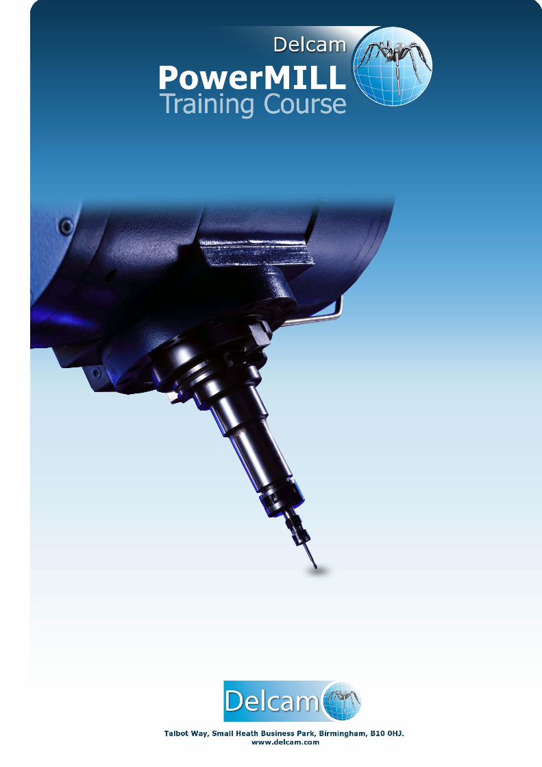
• Select an Isometric view and consider the machining options. Note the relatively high sides of the component and the orientation of the three recesses making it impossible to machine as 3 Axis (with the tooling aligned to the Z-Axis).
• Create a Workplane and move it by a distance of Z175 to clear the top of the component and Name it as ztop175_A and make it Active.
Note: Workplane alignment for compound angles is easier to achieve using PowerSHAPE
(If familiar with the commands). A limited functionality version called Wireframe
modelling is directly accessible (as standard) from PowerMILL. Create a Pattern to enable
access to the Wireframe modelling, select the model and Insert – Wireframe modelling.
Create, reposition, and re-orientate Workplanes dynamically as required. Otherwise use the
direct method from within PowerMILL as described on the following page.
1. 3+2 Axis Machining PowerMILL Five Axis
1.2 Issue PMILL 9 Five Axis
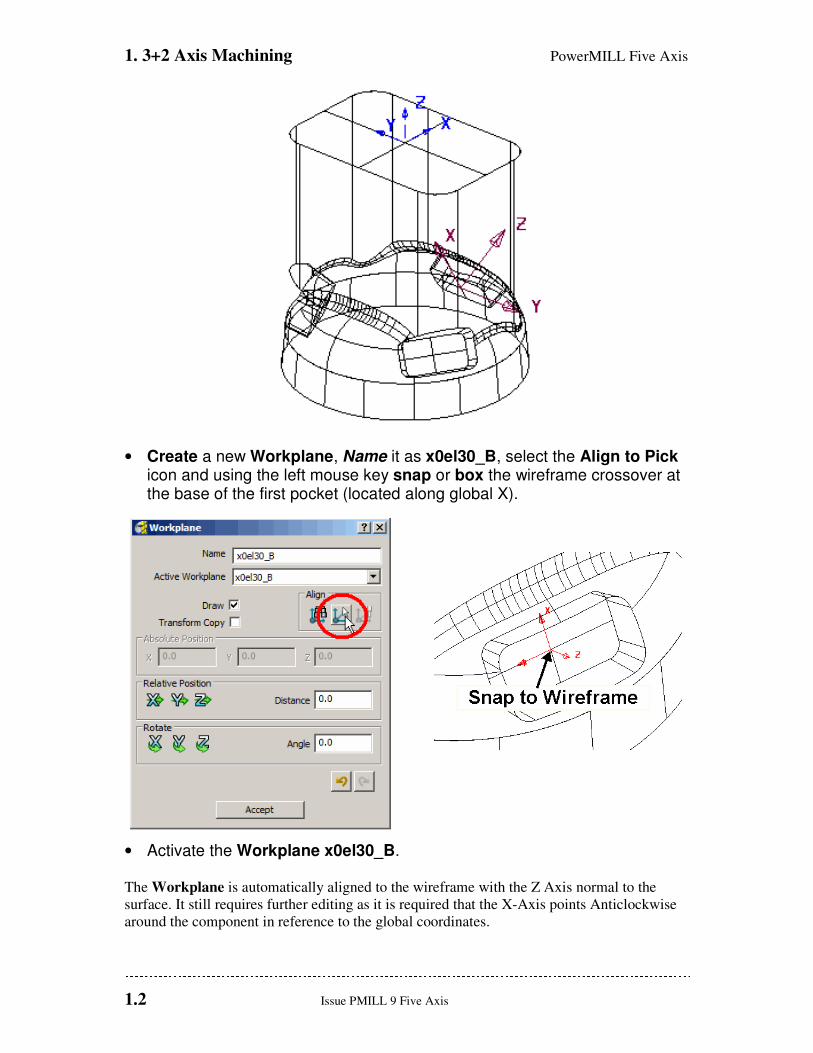
• Create a new Workplane, Name it as x0el30_B, select the Align to Pick icon and using the left mouse key snap or box the wireframe crossover at the base of the first pocket (located along global X).
• Activate the Workplane x0el30_B. The Workplane is automatically aligned to the wireframe with the Z Axis normal to the
surface. It still requires further editing as it is required that the X-Axis points Anticlockwise
around the component in reference to the global coordinates.
PowerMILL Five Axis 1. 3+2 Axis Machining
Issue PMILL 9 Five Axis 1.3
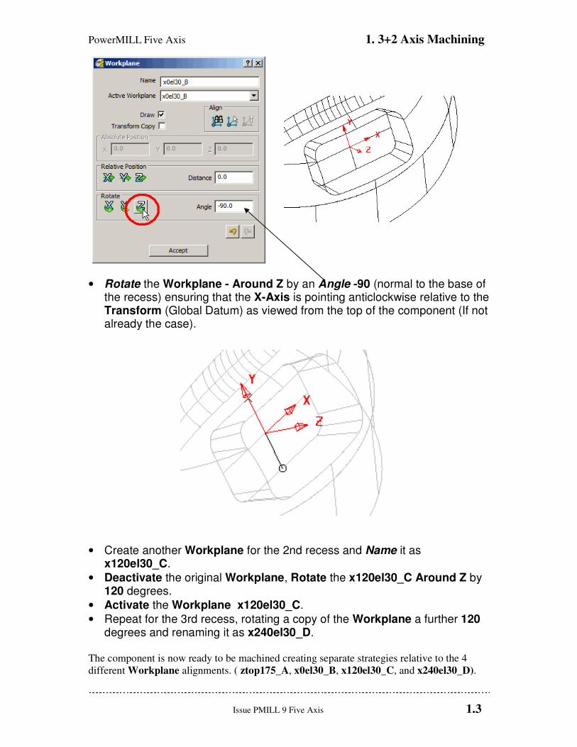
• Rotate the Workplane - Around Z by an Angle -90 (normal to the base of the recess) ensuring that the X-Axis is pointing anticlockwise relative to the Transform (Global Datum) as viewed from the top of the component (If not already the case).
• Create another Workplane for the 2nd recess and Name it as x120el30_C.
• Deactivate the original Workplane, Rotate the x120el30_C Around Z by 120 degrees.
• Activate the Workplane x120el30_C.
• Repeat for the 3rd recess, rotating a copy of the Workplane a further 120 degrees and renaming it as x240el30_D.
The component is now ready to be machined creating separate strategies relative to the 4
different Workplane alignments. ( ztop175_A, x0el30_B, x120el30_C, and x240el30_D).
1. 3+2 Axis Machining PowerMILL Five Axis
1.4 Issue PMILL 9 Five Axis
For each of the 3 Pockets a rectangular material Block will be created locally, relative to the
required 3+2 Workplane. A Model Boundary will also be created around each pocket to be
included in the machining strategies (Machine Inside Boundary).
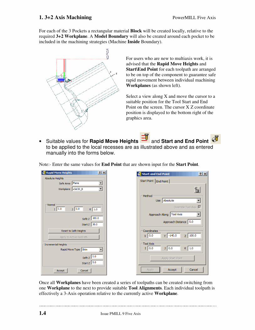
For users who are new to multiaxis work, it is
advised that the Rapid Move Heights and
Start\End Point for each toolpath are arranged
to be on top of the component to guarantee safe
rapid movement between individual machining
Workplanes (as shown left).
Select a view along X and move the cursor to a
suitable position for the Tool Start and End
Point on the screen. The cursor X Z coordinate
position is displayed to the bottom right of the
graphics area.
• Suitable values for Rapid Move Heights and Start and End Point to be applied to the local recesses are as illustrated above and as entered manually into the forms below.
Note:- Enter the same values for End Point that are shown input for the Start Point.
Once all Workplanes have been created a series of toolpaths can be created switching from
one Workplane to the next to provide suitable Tool Alignments. Each individual toolpath is
effectively a 3-Axis operation relative to the currently active Workplane.

PowerMILL Five Axis 1. 3+2 Axis Machining
Issue PMILL 9 Five Axis 1.5
• Create machining Strategies as listed below to the specified 3+2 Workplanes.
TOOL WORKPLANE STRATEGY STOCK TOOLPATH
3-AXIS ROUGHING
DIA 40 Tiprad 6 ztop175_A OFFSET 1.0mm D40t6rgh-a1
Stepover 35 - Stepdown 10
3-AXIS SEMI-FINISH DIA 40 Tiprad 6 ztop175_A CONSTANT Z 0.5mm D40t6sem-a1
Stepdown 2
3+2 ROUGH RECESSES DIA 10 Tiprad 1 x0el30_B OFFSET 0.5mm D10t1rgh-b1
DIA 10 Tiprad 1 x120el30_C OFFSET 0.5mm D10t1rgh-c1
DIA 10 Tiprad 1 x240el30_D OFFSET 0.5mm D10t1rgh-d1
Stepover 3 - Stepdown 2
3+2 FINISH RECESSES DIA 10 Tiprad 1 x0el30_B OPTIMISED CONST Z 0mm D10t1fin-b1
DIA 10 Tiprad 1 x120el30_C OPTIMISED CONST Z 0mm D10t1fin-c1
DIA 10 Tiprad 1 x240el30_D OPTIMISED CONST Z 0mm D10t1fin-d1
Stepover 2 - Stepdown 1
• Save the Project as:- D:\users\training\COURSEWORK\PowerMILL-Projects\3+2example (It will be used again later during the Swarf Machining chapter).
After the creation of toolpaths for 3 + 2 Axis valid ncdata can only be output using a
compatible post-processor. For programs containing multi-alignment toolpaths the NC
Programs output options create the ncdata from one datum (In this case the Workplane -
ztop175_A). This option is selected in the NC Preferences or NC Program Settings form.
1. 3+2 Axis Machining PowerMILL Five Axis
1.6 Issue PMILL 9 Five Axis
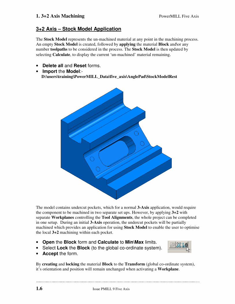
3+2 Axis – Stock Model Application
The Stock Model represents the un-machined material at any point in the machining process.
An empty Stock Model is created, followed by applying the material Block and\or any
number toolpaths to be considered in the process. The Stock Model is then updated by
selecting Calculate, to display the current ‘un-machined’ material remaining.
• Delete all and Reset forms.
• Import the Model:- D:\users\training\PowerMILL_Data\five_axis\AnglePad\StockModelRest
The model contains undercut pockets, which for a normal 3-Axis application, would require
the component to be machined in two separate set ups. However, by applying 3+2 with
separate Workplanes controlling the Tool Alignments, the whole project can be completed
in one setup. During an initial 3-Axis operation, the undercut pockets will be partially
machined which provides an application for using Stock Model to enable the user to optimise
the local 3+2 machining within each pocket.
• Open the Block form and Calculate to Min\Max limits.
• Select Lock the Block (to the global co-ordinate system).
• Accept the form. By creating and locking the material Block to the Transform (global co-ordinate system),
it’s orientation and position will remain unchanged when activating a Workplane.
PowerMILL Five Axis 1. 3+2 Axis Machining
Issue PMILL 9 Five Axis 1.7
• Create a Dia 12 - tip radius 1 tool and Rename D12T1.
• Create a Dia 16 - tip radius 3 tool and Rename D16T3.
• In the Rapid Move Heights form Reset To Safe Heights with Rapid Move Type set to Skim.
• Set both Start Point and End Point as Block Centre Safe.
• Activate the tool D16T3.
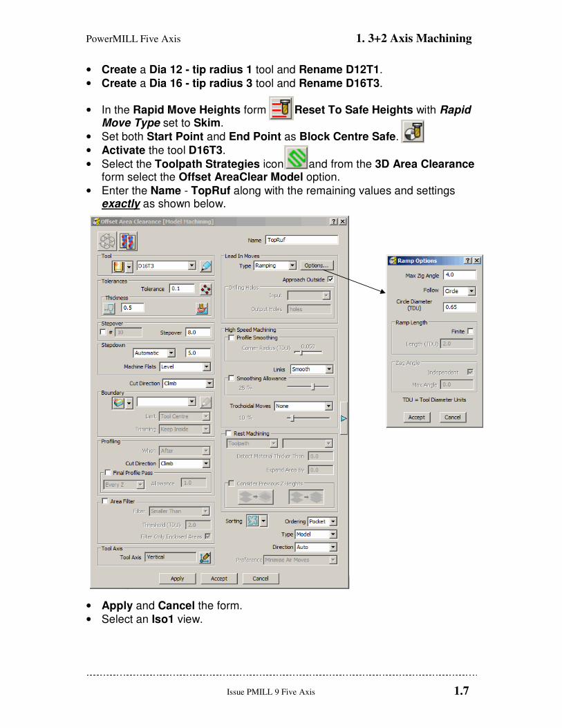
• Select the Toolpath Strategies icon and from the 3D Area Clearance form select the Offset AreaClear Model option.
• Enter the Name - TopRuf along with the remaining values and settings exactly as shown below.
• Apply and Cancel the form.
• Select an Iso1 view.
1. 3+2 Axis Machining PowerMILL Five Axis
1.8 Issue PMILL 9 Five Axis
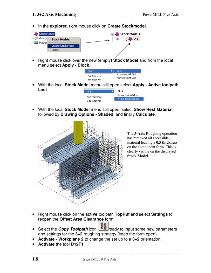
• In the explorer, right mouse click on Create Stockmodel.
• Right mouse click over the new (empty) Stock Model and from the local menu select Apply - Block.
• With the local Stock Model menu still open select Apply - Active toolpath Last.
• With the local Stock Model menu still open, select Show Rest Material, followed by Drawing Options - Shaded, and finally Calculate.
The 3-Axis Roughing operation
has removed all accessible
material leaving a 0.5 thickness
on the component form. This is
clearly visible on the displayed
Stock Model.
• Right mouse click on the active toolpath TopRuf and select Settings to reopen the Offset Area Clearance form.
• Select the Copy Toolpath icon ready to input some new parameters and settings for the 3+2 roughing strategy (keep the form open).
• Activate - Workplane 2 to change the set up to a 3+2 orientation.
• Activate the tool D12T1.
PowerMILL Five Axis 1. 3+2 Axis Machining
Issue PMILL 9 Five Axis 1.9
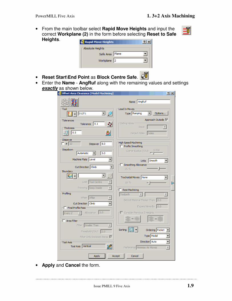
• From the main toolbar select Rapid Move Heights and input the correct Workplane (2) in the form before selecting Reset to Safe Heights.
• Reset Start\End Point as Block Centre Safe.
• Enter the Name - AngRuf along with the remaining values and settings exactly as shown below.
• Apply and Cancel the form.
1. 3+2 Axis Machining PowerMILL Five Axis
1.10 Issue PMILL 9 Five Axis
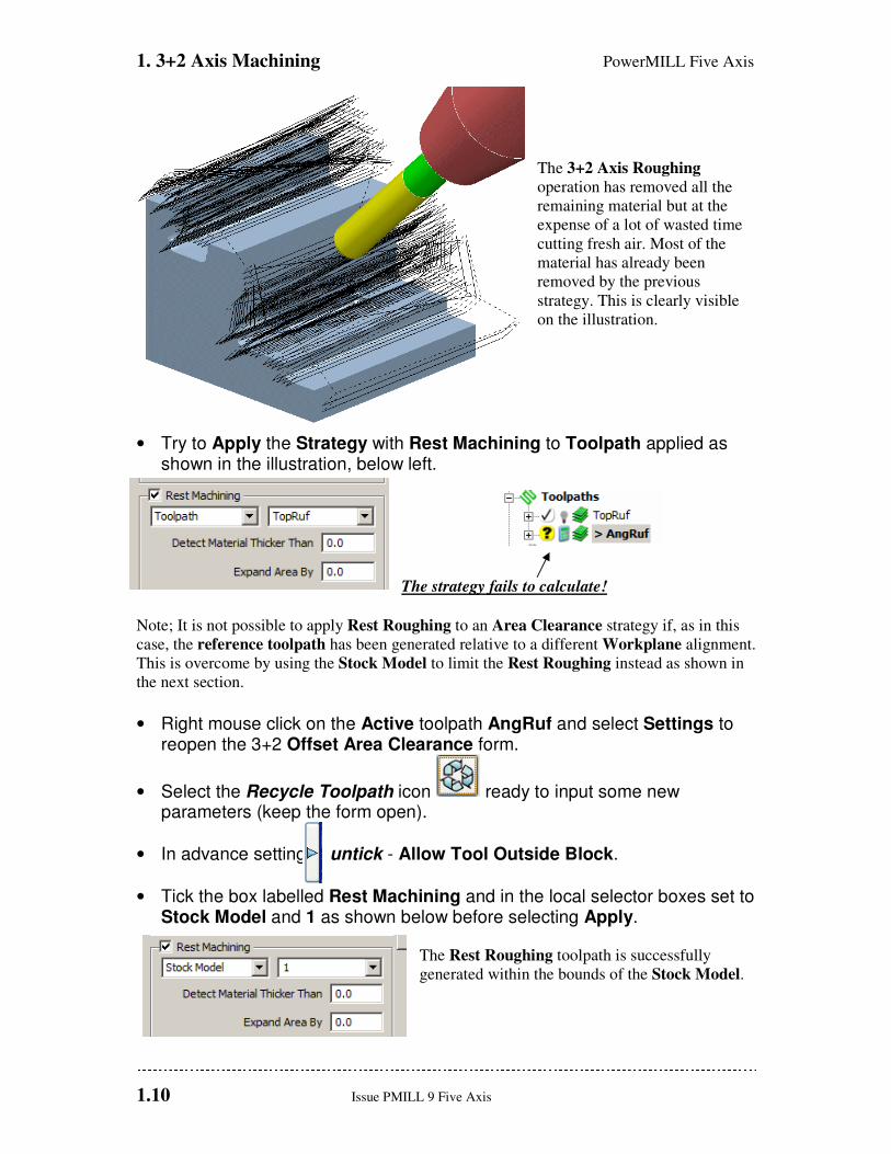
The 3+2 Axis Roughing
operation has removed all the
remaining material but at the
expense of a lot of wasted time
cutting fresh air. Most of the
material has already been
removed by the previous
strategy. This is clearly visible
on the illustration.
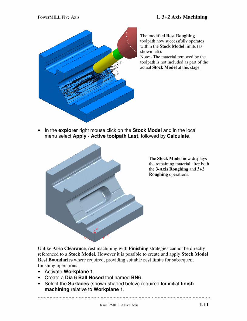
• Try to Apply the Strategy with Rest Machining to Toolpath applied as shown in the illustration, below left.
The strategy fails to calculate!
Note; It is not possible to apply Rest Roughing to an Area Clearance strategy if, as in this
case, the reference toolpath has been generated relative to a different Workplane alignment.
This is overcome by using the Stock Model to limit the Rest Roughing instead as shown in
the next section.
• Right mouse click on the Active toolpath AngRuf and select Settings to reopen the 3+2 Offset Area Clearance form.
• Select the Recycle Toolpath icon ready to input some new parameters (keep the form open).
• In advance settings untick - Allow Tool Outside Block.
• Tick the box labelled Rest Machining and in the local selector boxes set to Stock Model and 1 as shown below before selecting Apply.
The Rest Roughing toolpath is successfully
generated within the bounds of the Stock Model.
PowerMILL Five Axis 1. 3+2 Axis Machining
Issue PMILL 9 Five Axis 1.11
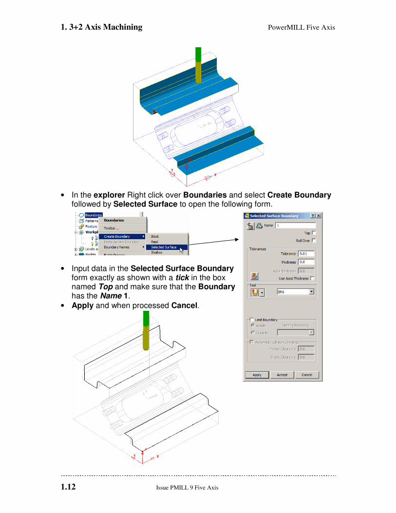
The modified Rest Roughing
toolpath now successfully operates
within the Stock Model limits (as
shown left).
Note:- The material removed by the
toolpath is not included as part of the
actual Stock Model at this stage.
• In the explorer right mouse click on the Stock Model and in the local menu select Apply - Active toolpath Last, followed by Calculate.
The Stock Model now displays
the remaining material after both
the 3-Axis Roughing and 3+2
Roughing operations.
Unlike Area Clearance, rest machining with Finishing strategies cannot be directly
referenced to a Stock Model. However it is possible to create and apply Stock Model
Rest Boundaries where required, providing suitable rest limits for subsequent
finishing operations.
• Activate Workplane 1.
• Create a Dia 6 Ball Nosed tool named BN6.
• Select the Surfaces (shown shaded below) required for initial finish machining relative to Workplane 1.
1. 3+2 Axis Machining PowerMILL Five Axis
1.12 Issue PMILL 9 Five Axis
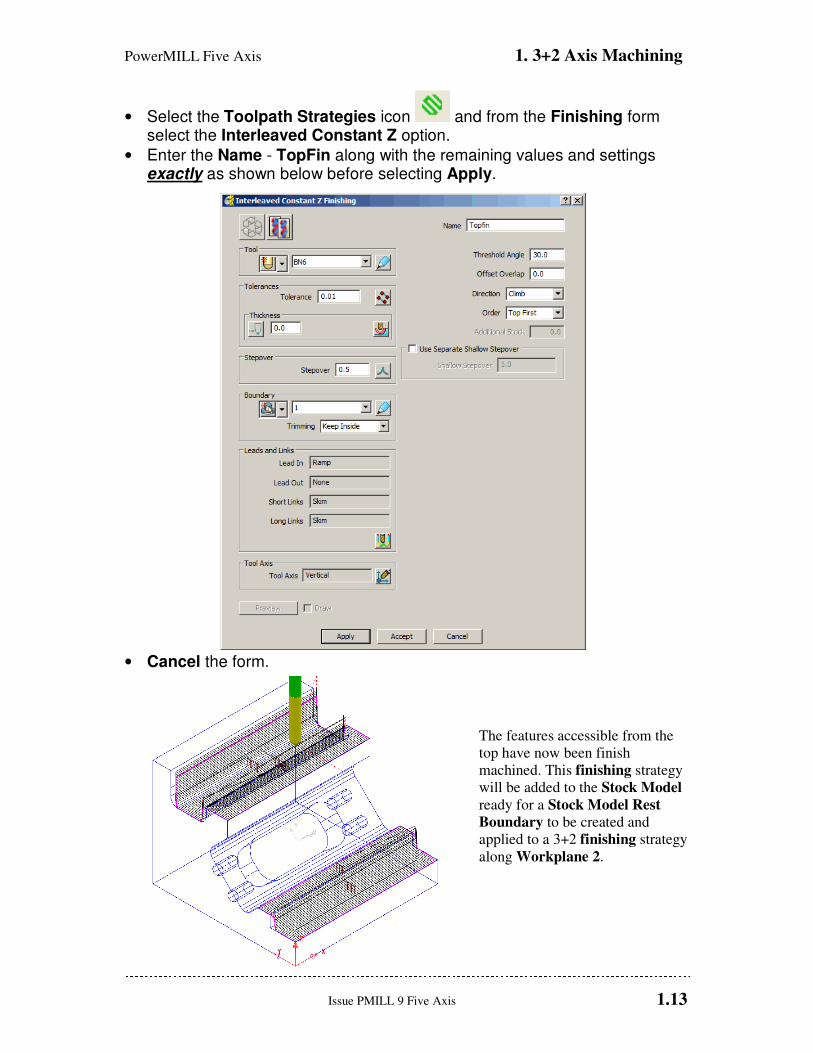
• In the explorer Right click over Boundaries and select Create Boundary followed by Selected Surface to open the following form.
• Input data in the Selected Surface Boundary form exactly as shown with a tick in the box named Top and make sure that the Boundary has the Name 1.
• Apply and when processed Cancel.
PowerMILL Five Axis 1. 3+2 Axis Machining
Issue PMILL 9 Five Axis 1.13
• Select the Toolpath Strategies icon and from the Finishing form select the Interleaved Constant Z option.
• Enter the Name - TopFin along with the remaining values and settings exactly as shown below before selecting Apply.
• Cancel the form.
The features accessible from the
top have now been finish
machined. This finishing strategy
will be added to the Stock Model
ready for a Stock Model Rest
Boundary to be created and
applied to a 3+2 finishing strategy
along Workplane 2.

1. 3+2 Axis Machining PowerMILL Five Axis
1.14 Issue PMILL 9 Five Axis
• With the local Stock Model menu still open select Apply - Active toolpath last
• With the local Stock Model menu still open, select Show Rest Material, followed by Drawing Options - Shaded, and finally Calculate.
• Activate Workplane 2.
• Select an ISO 1 view to display the component relative to the Workplane 2 orientation.
• In the explorer Right click over Boundaries and select Create Boundary followed by Stock Model Rest to open the following form.
• Input data in the Stock Model Rest Boundary form exactly as shown and ensure that the Boundary has the Name 2.
• Apply and when processed Cancel.

PowerMILL Five Axis 1. 3+2 Axis Machining
Issue PMILL 9 Five Axis 1.15
• Select the Toolpath Strategies icon and from the Finishing form select the Interleaved Constant Z option.
• Enter the Name - AngFin along with the remaining values and settings exactly as shown below before selecting Apply.
• Cancel the form.
1. 3+2 Axis Machining PowerMILL Five Axis
1.16 Issue PMILL 9 Five Axis
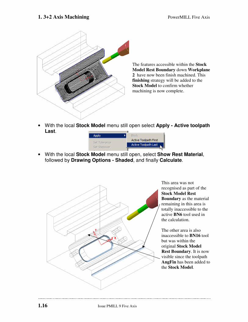
The features accessible within the Stock
Model Rest Boundary down Workplane
2 have now been finish machined. This
finishing strategy will be added to the
Stock Model to confirm whether
machining is now complete.
• With the local Stock Model menu still open select Apply - Active toolpath Last.
• With the local Stock Model menu still open, select Show Rest Material, followed by Drawing Options - Shaded, and finally Calculate.
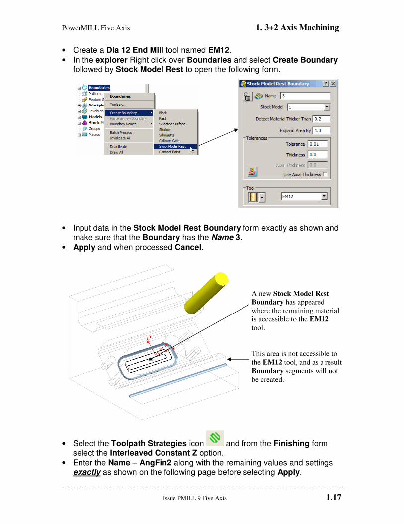
This area was not
recognised as part of the
Stock Model Rest Boundary as the material
remaining in this area is
totally inaccessible to the
active BN6 tool used in
the calculation.
The other area is also
inaccessible to BN16 tool
but was within the
original Stock Model
Rest Boundary. It is now
visible since the toolpath
AngFin has been added to
the Stock Model.
PowerMILL Five Axis 1. 3+2 Axis Machining
Issue PMILL 9 Five Axis 1.17
• Create a Dia 12 End Mill tool named EM12.
• In the explorer Right click over Boundaries and select Create Boundary followed by Stock Model Rest to open the following form.
• Input data in the Stock Model Rest Boundary form exactly as shown and make sure that the Boundary has the Name 3.
• Apply and when processed Cancel.
A new Stock Model Rest
Boundary has appeared
where the remaining material
is accessible to the EM12
tool.
This area is not accessible to
the EM12 tool, and as a result
Boundary segments will not
be created.
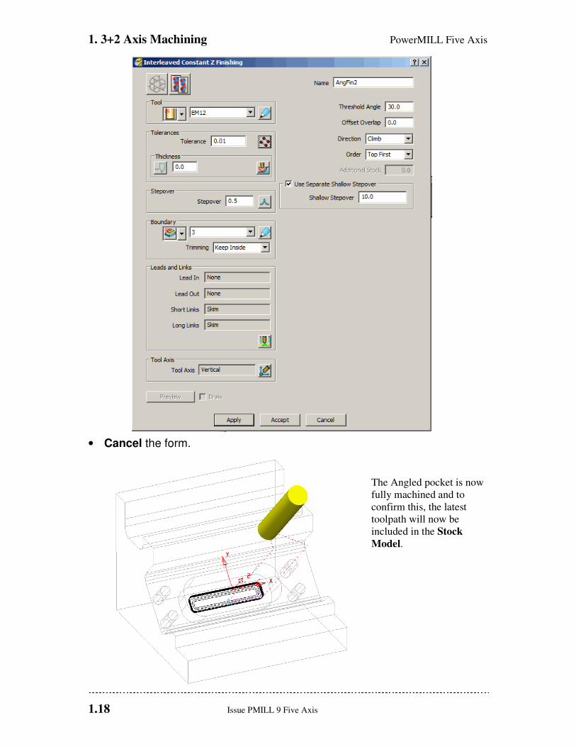
• Select the Toolpath Strategies icon and from the Finishing form select the Interleaved Constant Z option.
• Enter the Name – AngFin2 along with the remaining values and settings exactly as shown on the following page before selecting Apply.
1. 3+2 Axis Machining PowerMILL Five Axis
1.18 Issue PMILL 9 Five Axis
• Cancel the form.
The Angled pocket is now
fully machined and to
confirm this, the latest
toolpath will now be
included in the Stock
Model.
PowerMILL Five Axis 1. 3+2 Axis Machining
Issue PMILL 9 Five Axis 1.19
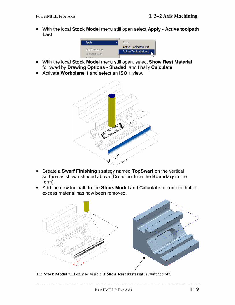
• With the local Stock Model menu still open select Apply - Active toolpath Last.
• With the local Stock Model menu still open, select Show Rest Material, followed by Drawing Options - Shaded, and finally Calculate.
• Activate Workplane 1 and select an ISO 1 view.
• Create a Swarf Finishing strategy named TopSwarf on the vertical surface as shown shaded above (Do not include the Boundary in the form).
• Add the new toolpath to the Stock Model and Calculate to confirm that all excess material has now been removed.
The Stock Model will only be visible if Show Rest Material is switched off.

1. 3+2 Axis Machining PowerMILL Five Axis
1.20 Issue PMILL 9 Five Axis
3+2 Axis - Drilling Example (For users with MultiAxis licence)
The PowerMILL - Drilling options operate on Hole Features and not directly on the
Model. This enables drilling to take place without the need to modify or trim back the
existing surface data.
• Delete all entities and Import the model:- D:\users\training\PowerMILL_Data\five_axis\drill_5axis\drill5ax_ex1
• Do Not define a material Block and if one already exists, delete it (Blue Cross at top right corner of form).
Any cylindrical surfaces within the selection will automatically be recognised as a Hole
Feature. In this example, with no Block defined, the Hole Features will be arranged with
the top at the end of maximum Z height.
If however, a Block is pre-defined, the orientation of an individual Hole Feature occurs with
the top of the hole being nearest to the upper Z or lower Z, face of the material Block.
Note: It is possible, if required, to Reverse the Holes in a Feature Set using the local Edit
options combined with dynamically selecting the affected Hole Features.
• Reset the Rapid Move Heights (Safe Z, Start Z) and then, set the
Start\End Points to Use - Block Centre Safe.
• Select all the surface data in the graphics window and then right mouse click Feature Sets in the PowerMILL Explorer.
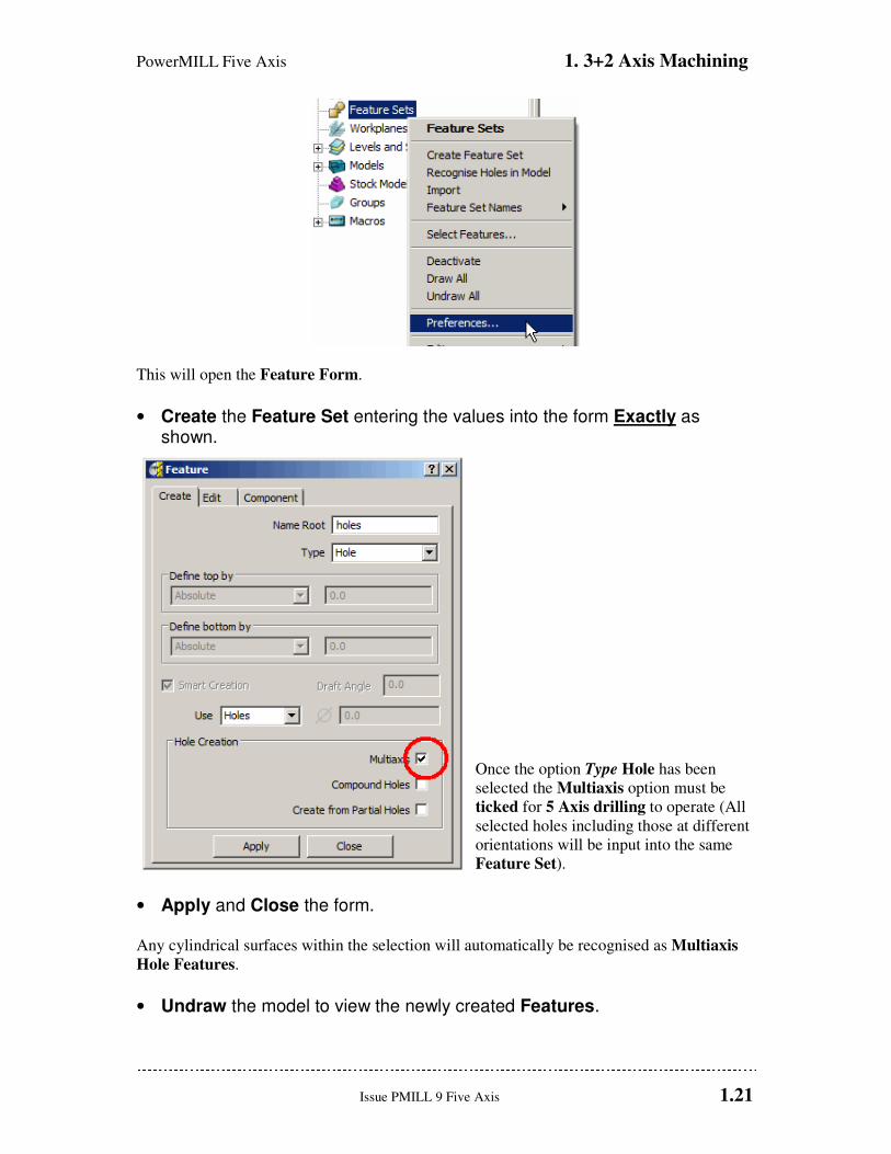
• Select the option Preferences.
PowerMILL Five Axis 1. 3+2 Axis Machining
Issue PMILL 9 Five Axis 1.21
This will open the Feature Form.
• Create the Feature Set entering the values into the form Exactly as shown.
Once the option Type Hole has been
selected the Multiaxis option must be
ticked for 5 Axis drilling to operate (All
selected holes including those at different
orientations will be input into the same
Feature Set).
• Apply and Close the form. Any cylindrical surfaces within the selection will automatically be recognised as Multiaxis
Hole Features.
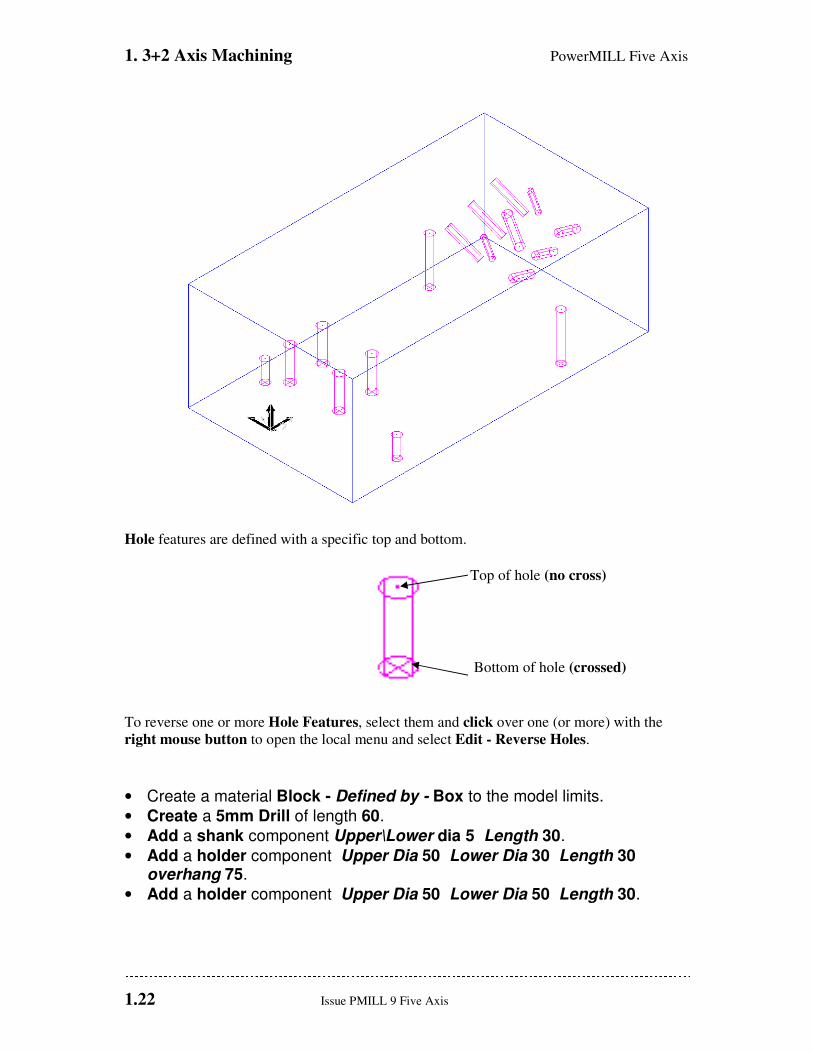
• Undraw the model to view the newly created Features.
1. 3+2 Axis Machining PowerMILL Five Axis
1.22 Issue PMILL 9 Five Axis
Hole features are defined with a specific top and bottom.
Top of hole (no cross)
Bottom of hole (crossed)
To reverse one or more Hole Features, select them and click over one (or more) with the
right mouse button to open the local menu and select Edit - Reverse Holes.
• Create a material Block - Defined by - Box to the model limits.
• Create a 5mm Drill of length 60.
• Add a shank component Upper\Lower dia 5 Length 30.
• Add a holder component Upper Dia 50 Lower Dia 30 Length 30 overhang 75.
• Add a holder component Upper Dia 50 Lower Dia 50 Length 30.

PowerMILL Five Axis 1. 3+2 Axis Machining
Issue PMILL 9 Five Axis 1.23
• Select the Toolpath Strategies icon and in the New strategies form select the Drilling form.
• In the Drilling form select the option Drilling.
• Rename the toolpath DRILL5.
• In the Drilling form click the Select tab to open the Feature Selection form.
• By clicking the Select tab in the Feature Selection form all the Hole Features will be selected in the Active - Feature Set.
• Simulate the toolpath.
The Multiaxis options are automatically
recognised enabling the user to create a
single Feature Set from components that
exist at different tool alignments and
machine them in one go. Without the
licence the Recognise Holes in Model
option can be applied from the Feature Set
menu to create separate 3+2 - Hole
Features. This command segregates the
Features into separate Feature Sets each
with it’s own Workplane, to provide the
necessary 3+2 - Z Axis alignment.
1. 3+2 Axis Machining PowerMILL Five Axis
1.24 Issue PMILL 9 Five Axis
The two 6mm Hole Features are to be Tapped. The point angle of the 5mm Drill has left a
conical shape at the bottom of the holes. When the holes are Tapped it will be necessary to
stop short within the full diameter range by applying a suitable Axial Thickness value.
• Create a 6mm Tapping Tool of length 25.
• Add a Shank, Upper - Dia 4, Lower Dia 4, Length 40
• Add a Holder, Upper- Dia 30, Lower Dia 30, Length 20, Overhang 60.
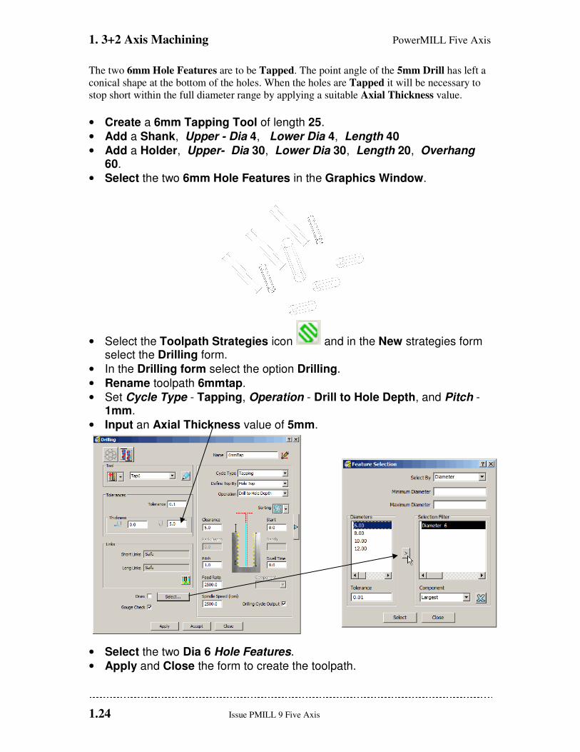
• Select the two 6mm Hole Features in the Graphics Window.
• Select the Toolpath Strategies icon and in the New strategies form select the Drilling form.
• In the Drilling form select the option Drilling.
• Rename toolpath 6mmtap.
• Set Cycle Type - Tapping, Operation - Drill to Hole Depth, and Pitch - 1mm.
• Input an Axial Thickness value of 5mm.
• Select the two Dia 6 Hole Features.
• Apply and Close the form to create the toolpath.
PowerMILL Five Axis 1. 3+2 Axis Machining
Issue PMILL 9 Five Axis 1.25
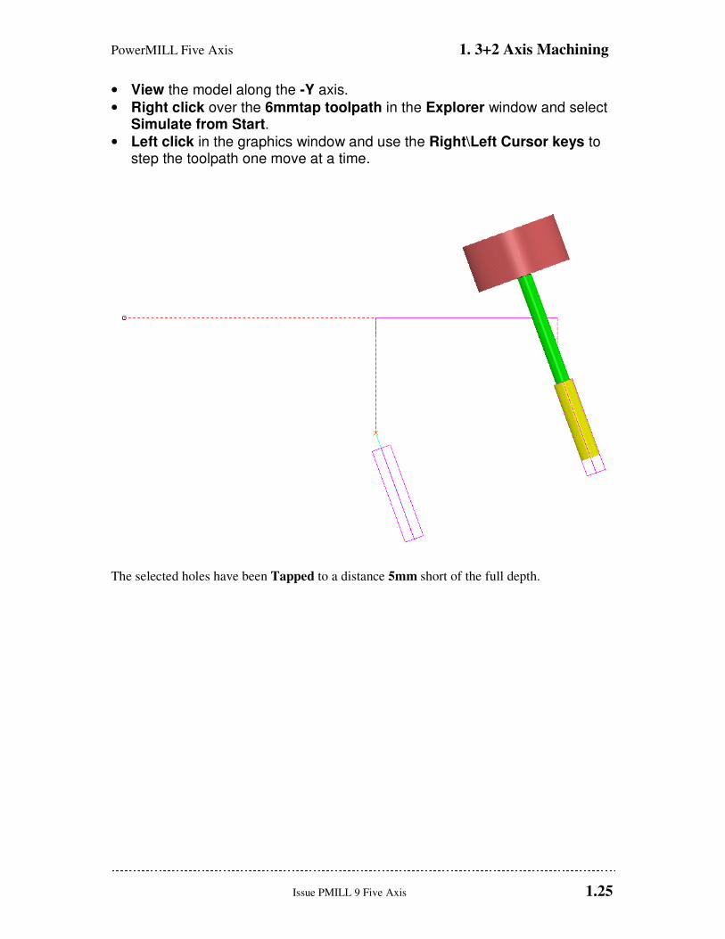
• View the model along the -Y axis.
• Right click over the 6mmtap toolpath in the Explorer window and select Simulate from Start.
• Left click in the graphics window and use the Right\Left Cursor keys to step the toolpath one move at a time.
The selected holes have been Tapped to a distance 5mm short of the full depth.

1. 3+2 Axis Machining PowerMILL Five Axis
1.26 Issue PMILL 9 Five Axis
PowerMILL Five Axis 2. Tool Alignment
Issue PMILL 9 Five Axis 2.1
2. Five Axis Tool Alignment
Introduction
For 5-Axis applications where the machine tool head and\or table, rotates simultaneously
with the linear axis movements, PowerMILL provides a range of suitable Tool Alignments
and Machining Strategies.
5-Axis machining enables components normally requiring a series of 3-Axis operations to be
machined in one set-up. Tools can be re-aligned using 5-Axis control to provide access to the
base of steep or undercut features, which would otherwise inaccessible down the Z-Axis.
In 5-Axis applications, as well as the normal, default gouge checking, a range of options exist
to ensure that no part of the head, spindle or tooling clash with the component between
different strategies. In all cases it is essential to carry out a thorough visual inspection of the
results.
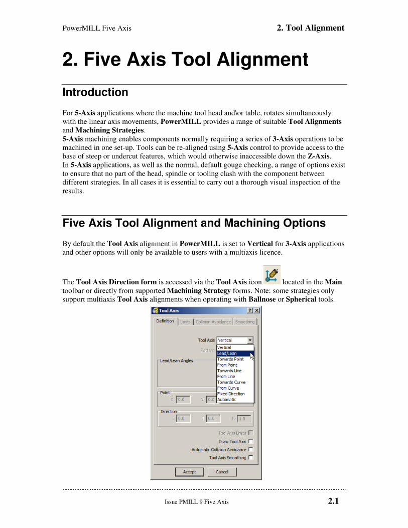
Five Axis Tool Alignment and Machining Options
By default the Tool Axis alignment in PowerMILL is set to Vertical for 3-Axis applications
and other options will only be available to users with a multiaxis licence.
The Tool Axis Direction form is accessed via the Tool Axis icon located in the Main
toolbar or directly from supported Machining Strategy forms. Note: some strategies only
support multiaxis Tool Axis alignments when operating with Ballnose or Spherical tools.
2. Tool Alignment PowerMILL Five Axis
2.2 Issue PMILL 9 Five Axis
Lead\Lean Lead allows the tool to be aligned to a specified angle along the toolpath direction and Lean
a specified angle across the toolpath direction. If both angles are zero the tool will be aligned
along the normal of the toolpath. The normal of the toolpath is the direction along which it
was originally, projected onto the surface data during creation. For Pattern finishing this
will always be vertical and for Projection Finishing it will vary depending on the defined
projection, directional options.
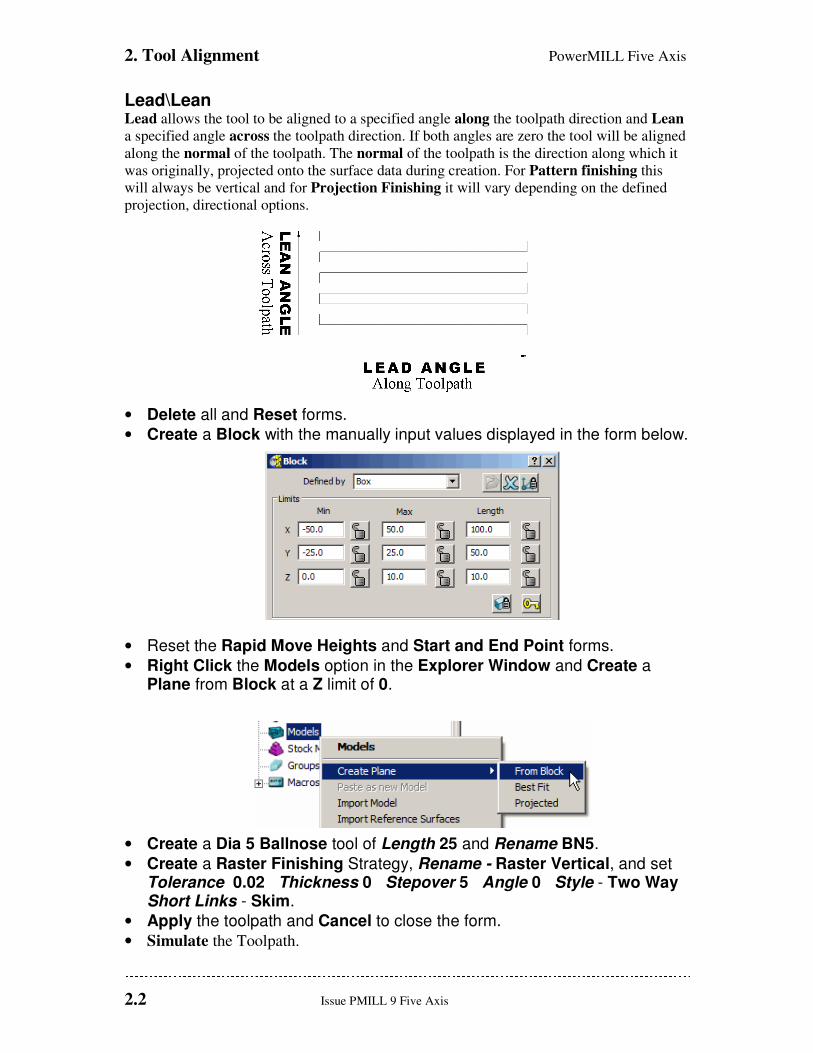
• Delete all and Reset forms.
• Create a Block with the manually input values displayed in the form below.
• Reset the Rapid Move Heights and Start and End Point forms.
• Right Click the Models option in the Explorer Window and Create a Plane from Block at a Z limit of 0.
• Create a Dia 5 Ballnose tool of Length 25 and Rename BN5.
• Create a Raster Finishing Strategy, Rename - Raster Vertical, and set Tolerance 0.02 Thickness 0 Stepover 5 Angle 0 Style - Two Way Short Links - Skim.
• Apply the toolpath and Cancel to close the form.
• Simulate the Toolpath.
PowerMILL Five Axis 2. Tool Alignment
Issue PMILL 9 Five Axis 2.3
A Raster toolpath has been
created with the tool aligned
vertically to the plane.
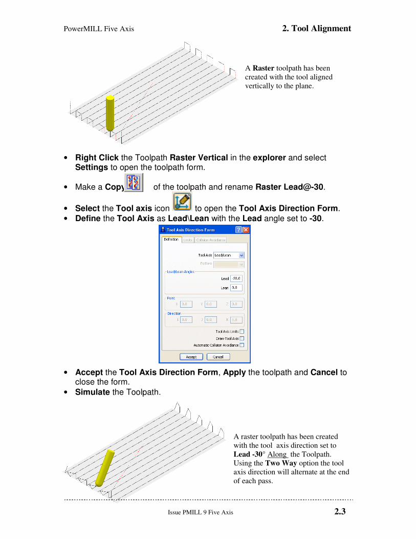
• Right Click the Toolpath Raster Vertical in the explorer and select Settings to open the toolpath form.
• Make a Copy of the toolpath and rename Raster Lead@-30.
• Select the Tool axis icon to open the Tool Axis Direction Form.
• Define the Tool Axis as Lead\Lean with the Lead angle set to -30.
• Accept the Tool Axis Direction Form, Apply the toolpath and Cancel to close the form.
• Simulate the Toolpath.
A raster toolpath has been created
with the tool axis direction set to
Lead -30° Along the Toolpath.
Using the Two Way option the tool
axis direction will alternate at the end
of each pass.
2. Tool Alignment PowerMILL Five Axis
2.4 Issue PMILL 9 Five Axis
• Right Click the Toolpath Raster Lead@-30 in the Explorer Window and select Settings to open the toolpath form.
• Re-cycle the toolpath and change Style from Two Way to One Way.
• Apply the toolpath and Cancel to close the form.
With the Style set to One Way the
tool axis direction remains constant.
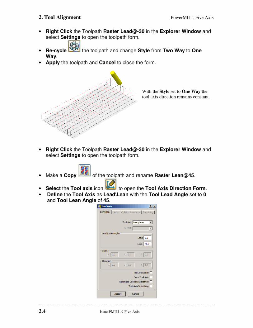
• Right Click the Toolpath Raster Lead@-30 in the Explorer Window and select Settings to open the toolpath form.
• Make a Copy of the toolpath and rename Raster Lean@45.
• Select the Tool axis icon to open the Tool Axis Direction Form.
• Define the Tool Axis as Lead\Lean with the Tool Lead Angle set to 0 and Tool Lean Angle of 45.
PowerMILL Five Axis 2. Tool Alignment
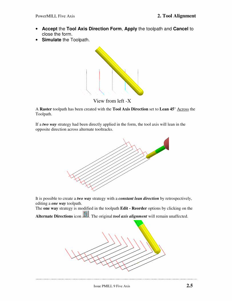
Issue PMILL 9 Five Axis 2.5
View from left -X
• Accept the Tool Axis Direction Form, Apply the toolpath and Cancel to close the form.
• Simulate the Toolpath.
A Raster toolpath has been created with the Tool Axis Direction set to Lean 45° Across the
Toolpath.
If a two way strategy had been directly applied in the form, the tool axis will lean in the
opposite direction across alternate tooltracks.
It is possible to create a two way strategy with a constant lean direction by retrospectively,
editing a one way toolpath.
The one way strategy is modified in the toolpath Edit - Reorder options by clicking on the
Alternate Directions icon . The original tool axis alignment will remain unaffected.
2. Tool Alignment PowerMILL Five Axis
2.6 Issue PMILL 9 Five Axis
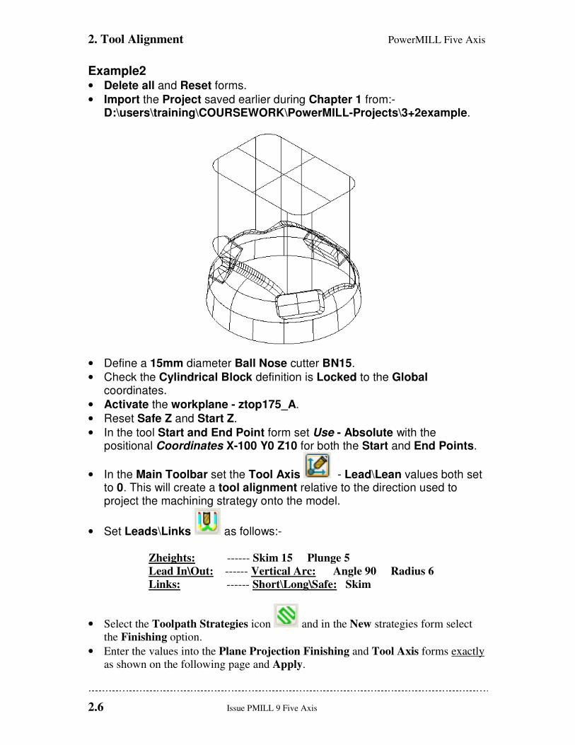
Example2 • Delete all and Reset forms.
• Import the Project saved earlier during Chapter 1 from:- D:\users\training\COURSEWORK\PowerMILL-Projects\3+2example.
• Define a 15mm diameter Ball Nose cutter BN15.
• Check the Cylindrical Block definition is Locked to the Global coordinates.
• Activate the workplane - ztop175_A.
• Reset Safe Z and Start Z.
• In the tool Start and End Point form set Use - Absolute with the positional Coordinates X-100 Y0 Z10 for both the Start and End Points.
• In the Main Toolbar set the Tool Axis - Lead\Lean values both set to 0. This will create a tool alignment relative to the direction used to project the machining strategy onto the model.
• Set Leads\Links as follows:-
Zheights: ------ Skim 15 Plunge 5
Lead In\Out: ------ Vertical Arc: Angle 90 Radius 6
Links: ------ Short\Long\Safe: Skim
• Select the Toolpath Strategies icon and in the New strategies form select
the Finishing option.
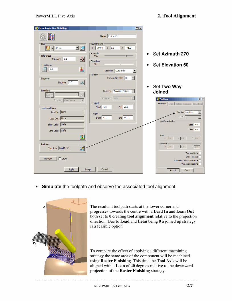
• Enter the values into the Plane Projection Finishing and Tool Axis forms exactly
as shown on the following page and Apply.
PowerMILL Five Axis 2. Tool Alignment
Issue PMILL 9 Five Axis 2.7
• Set Azimuth 270
• Set Elevation 50
• Set Two Way Joined
• Simulate the toolpath and observe the associated tool alignment.
The resultant toolpath starts at the lower corner and
progresses towards the centre with a Lead In and Lean Out
both set to 0 creating tool alignment relative to the projection
direction. Due to Lead and Lean being 0 a joined up strategy
is a feasible option.
To compare the effect of applying a different machining
strategy the same area of the component will be machined
using Raster Finishing. This time the Tool Axis will be
aligned with a Lean of 40 degrees relative to the downward
projection of the Raster Finishing strategy.
2. Tool Alignment PowerMILL Five Axis
2.8 Issue PMILL 9 Five Axis
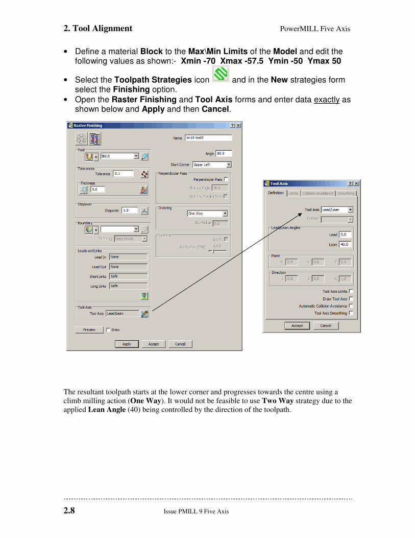
• Define a material Block to the Max\Min Limits of the Model and edit the following values as shown:- Xmin -70 Xmax -57.5 Ymin -50 Ymax 50
• Select the Toolpath Strategies icon and in the New strategies form select the Finishing option.
• Open the Raster Finishing and Tool Axis forms and enter data exactly as shown below and Apply and then Cancel.
The resultant toolpath starts at the lower corner and progresses towards the centre using a
climb milling action (One Way). It would not be feasible to use Two Way strategy due to the
applied Lean Angle (40) being controlled by the direction of the toolpath.
PowerMILL Five Axis 2. Tool Alignment
Issue PMILL 9 Five Axis 2.9
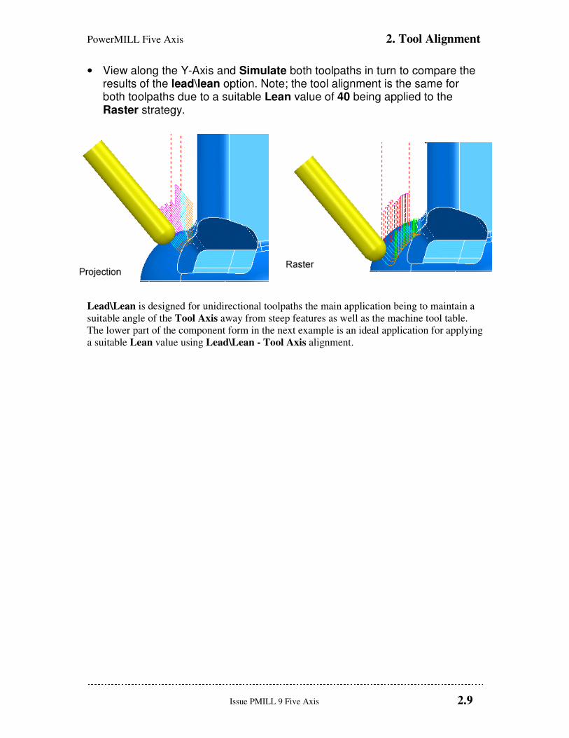
• View along the Y-Axis and Simulate both toolpaths in turn to compare the results of the lead\lean option. Note; the tool alignment is the same for both toolpaths due to a suitable Lean value of 40 being applied to the Raster strategy.
Lead\Lean is designed for unidirectional toolpaths the main application being to maintain a
suitable angle of the Tool Axis away from steep features as well as the machine tool table.
The lower part of the component form in the next example is an ideal application for applying
a suitable Lean value using Lead\Lean - Tool Axis alignment.
2. Tool Alignment PowerMILL Five Axis
2.10 Issue PMILL 9 Five Axis
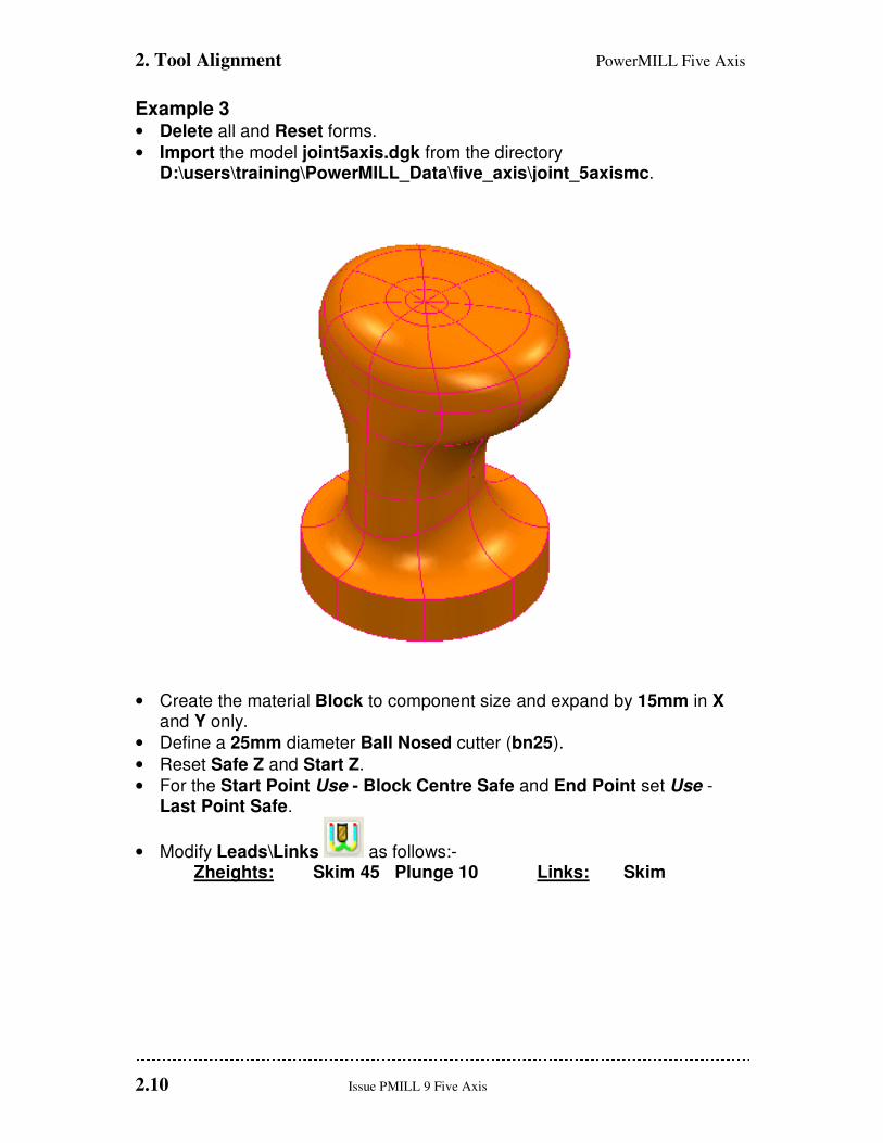
Example 3 • Delete all and Reset forms.
• Import the model joint5axis.dgk from the directory D:\users\training\PowerMILL_Data\five_axis\joint_5axismc.
• Create the material Block to component size and expand by 15mm in X and Y only.
• Define a 25mm diameter Ball Nosed cutter (bn25).
• Reset Safe Z and Start Z.
• For the Start Point Use - Block Centre Safe and End Point set Use - Last Point Safe.
• Modify Leads\Links as follows:- Zheights: Skim 45 Plunge 10 Links: Skim

PowerMILL Five Axis 2. Tool Alignment
Issue PMILL 9 Five Axis 2.11
• Select the Toolpath Strategies icon and in the New strategies form select the Finishing option.
• Open the Line Projection Finishing and Tool Axis forms and enter data exactly as shown and Apply.
• Set Azimuth 0
• Set Elevation 0
Note: The next section
continues with the machining
of the upper part of the
component.
2. Tool Alignment PowerMILL Five Axis
2.12 Issue PMILL 9 Five Axis
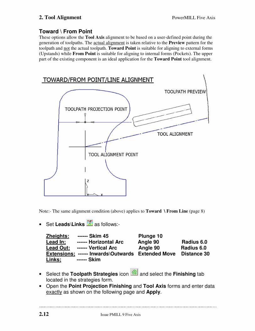
Toward \ From Point These options allow the Tool Axis alignment to be based on a user-defined point during the
generation of toolpaths. The actual alignment is taken relative to the Preview pattern for the
toolpath and not the actual toolpath. Toward Point is suitable for aligning to external forms
(Upstands) while From Point is suitable for aligning to internal forms (Pockets). The upper
part of the existing component is an ideal application for the Toward Point tool alignment.
Note:- The same alignment condition (above) applies to Toward \ From Line (page 8)
• Set Leads\Links as follows:- Zheights: ------ Skim 45 Plunge 10 Lead In; ------ Horizontal Arc Angle 90 Radius 6.0 Lead Out: ------ Vertical Arc Angle 90 Radius 6.0 Extensions; ------ Inwards\Outwards Extended Move Distance 30 Links; ------ Skim
• Select the Toolpath Strategies icon and select the Finishing tab located in the strategies form.
• Open the Point Projection Finishing and Tool Axis forms and enter data exactly as shown on the following page and Apply.
PowerMILL Five Axis 2. Tool Alignment
Issue PMILL 9 Five Axis 2.13
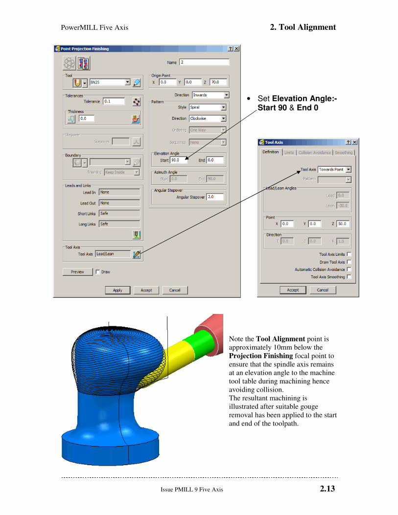
• Set Elevation Angle:-
Start 90 & End 0
Note the Tool Alignment point is
approximately 10mm below the
Projection Finishing focal point to
ensure that the spindle axis remains
at an elevation angle to the machine
tool table during machining hence
avoiding collision.
The resultant machining is
illustrated after suitable gouge
removal has been applied to the start
and end of the toolpath.

2. Tool Alignment PowerMILL Five Axis
2.14 Issue PMILL 9 Five Axis
Toward\From Line
These options allow tool axis alignment to be based on a user-defined line, specified by a
Vector direction through a suitably positioned XYZ coordinate. In this example the actual
alignment is towards the Preview pattern for the toolpath and not the final toolpath. Toward
Line is suitable for aligning to external forms (Upstands) while From Line is suitable for
aligning to internal forms (Pockets).
• From the main pulldown menus select File -Delete All.
• Import the model:- D:\users\training\PowerMILL_Data\five_axis\Casing from-line-model.dgk.
• Create a Dia 12mm Ball Nose cutter of Length 55 with Dia 12 Shank of Length 40, 1st Holder component Lower Dia 25 - Upper Dia 40 - Length 40, 2nd Holder component Upper\Lower Dia 40 - Length 60, Overhang 90.
• Define the Block (use Box) to the component limits.
• Reset Safe Heights.
• For both the Start Point and End Point set Use - Block Centre Safe.
• Set all Leads and Extensions to None, Zheights – Skim distance and Plunge distance to 5, Links - Short - Circular Arc and Long\Default - Skim.
• Select the Toolpath Strategies icon and in the New strategies form select the Finishing option.
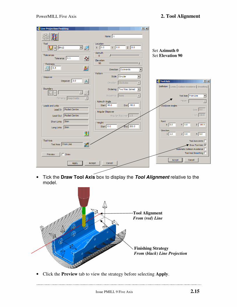
• Open the Line Projection Finishing and Tool Axis forms and enter data exactly as shown on the following page and select Preview.
PowerMILL Five Axis 2. Tool Alignment
Issue PMILL 9 Five Axis 2.15
Set Azimuth 0
Set Elevation 90
• Tick the Draw Tool Axis box to display the Tool Alignment relative to the model.
Tool Alignment
From (red) Line
Finishing Strategy
From (black) Line Projection
• Click the Preview tab to view the strategy before selecting Apply.
2. Tool Alignment PowerMILL Five Axis
2.16 Issue PMILL 9 Five Axis
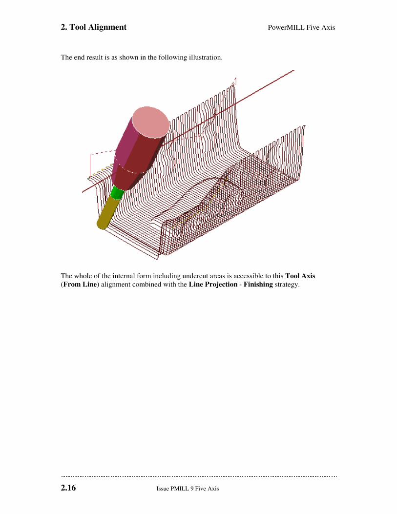
The end result is as shown in the following illustration.
The whole of the internal form including undercut areas is accessible to this Tool Axis
(From Line) alignment combined with the Line Projection - Finishing strategy.
PowerMILL Five Axis 2. Tool Alignment
Issue PMILL 9 Five Axis 2.17
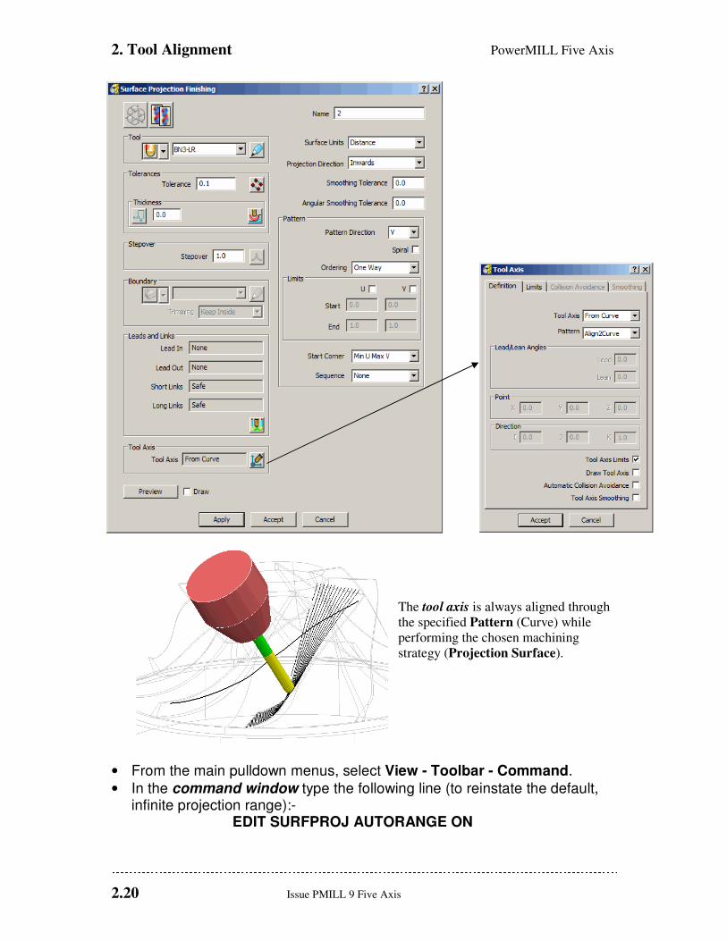
Toward\From Curve
These options allow the tool axis alignment to be through a user-defined curve (pattern),
during the creation of a 5-Axis toolpath. Note; The following chapter provides a more
detailed look at Projection Surface Finishing, the strategy used during this example.
• From the main pulldown menus select File -Delete All.
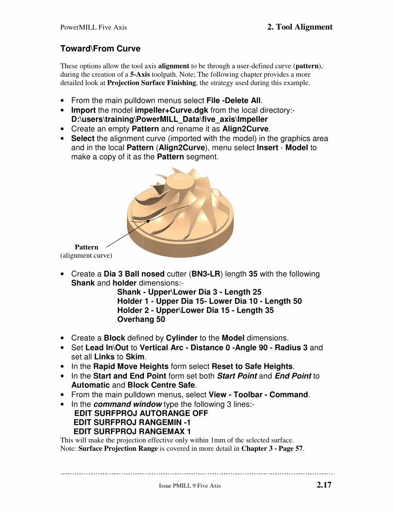
• Import the model impeller+Curve.dgk from the local directory:- D:\users\training\PowerMILL_Data\five_axis\Impeller
• Create an empty Pattern and rename it as Align2Curve.
• Select the alignment curve (imported with the model) in the graphics area and in the local Pattern (Align2Curve), menu select Insert - Model to make a copy of it as the Pattern segment.
Pattern
(alignment curve)
• Create a Dia 3 Ball nosed cutter (BN3-LR) length 35 with the following Shank and holder dimensions:-
Shank - Upper\Lower Dia 3 - Length 25 Holder 1 - Upper Dia 15- Lower Dia 10 - Length 50 Holder 2 - Upper\Lower Dia 15 - Length 35 Overhang 50
• Create a Block defined by Cylinder to the Model dimensions.
• Set Lead In\Out to Vertical Arc - Distance 0 -Angle 90 - Radius 3 and set all Links to Skim.
• In the Rapid Move Heights form select Reset to Safe Heights.
• In the Start and End Point form set both Start Point and End Point to Automatic and Block Centre Safe.
• From the main pulldown menus, select View - Toolbar - Command.
• In the command window type the following 3 lines:- EDIT SURFPROJ AUTORANGE OFF EDIT SURFPROJ RANGEMIN -1 EDIT SURFPROJ RANGEMAX 1 This will make the projection effective only within 1mm of the selected surface.
Note: Surface Projection Range is covered in more detail in Chapter 3 - Page 57.

2. Tool Alignment PowerMILL Five Axis
2.18 Issue PMILL 9 Five Axis
• Close the command window by clicking on the black cross at the top left corner.
• Select the underside, blade surface nearest to the Pattern for use with the Projection Surface strategy.
• Select the Toolpath Strategies icon and in the New strategies form select
the Finishing option.
• Open the Projection Surface Finishing and Tool Axis forms entering the data
exactly as shown below and select Apply.
PowerMILL Five Axis 2. Tool Alignment
Issue PMILL 9 Five Axis 2.19
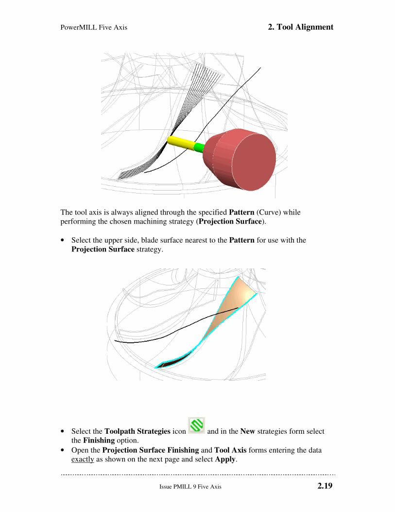
The tool axis is always aligned through the specified Pattern (Curve) while
performing the chosen machining strategy (Projection Surface).
• Select the upper side, blade surface nearest to the Pattern for use with the
Projection Surface strategy.
• Select the Toolpath Strategies icon and in the New strategies form select
the Finishing option.
• Open the Projection Surface Finishing and Tool Axis forms entering the data
exactly as shown on the next page and select Apply.
2. Tool Alignment PowerMILL Five Axis
2.20 Issue PMILL 9 Five Axis
The tool axis is always aligned through
the specified Pattern (Curve) while
performing the chosen machining
strategy (Projection Surface).
• From the main pulldown menus, select View - Toolbar - Command.
• In the command window type the following line (to reinstate the default, infinite projection range):-
EDIT SURFPROJ AUTORANGE ON

PowerMILL Five Axis 2. Tool Alignment
Issue PMILL 9 Five Axis 2.21
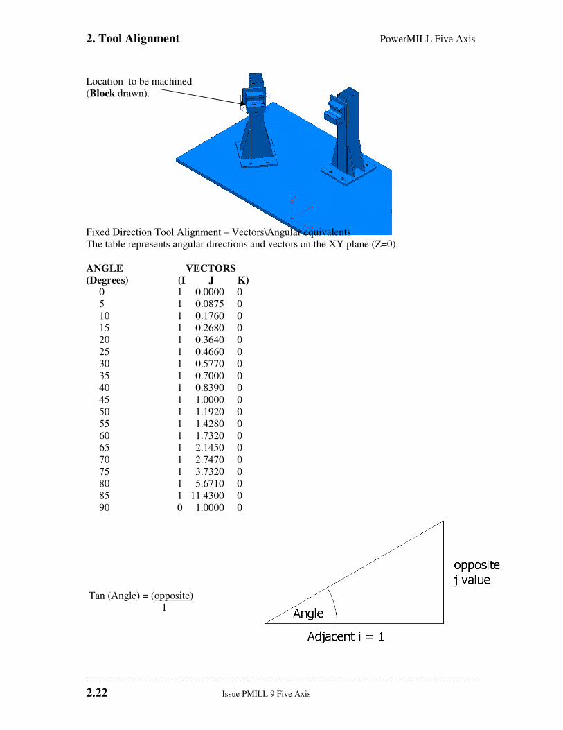
Fixed Direction
This allows the tool axis to be set to a fixed angle, specified by Vector, defined by the user. In
this case it is applied to the finishing of an undercut form on the 5axis_fixture.dgk model.
• From the main pulldown menus select File -Delete All.
• Reset forms. • Import the model D:\users\training\PowerMILL_Data\five_axis\Autorail_and_Fixture\5axis_fixture.dgk
• Create a Dia 16 Ball nosed cutter (BN16).
• Set all Leads and Extensions to None.
The model consists of components existing on two separate levels, Fixture:surfs and
Part:surfs. All items on a specific level can be drawn or undrawn from the levels area in the
explorer window. In this example it is only required to machine the part of the component
stored on Fixture:surfs using a Fixed Direction alignment which means that the items
stored on Part:surfs must be temporarily discarded to allow access.
• Undraw the Part: surfs level from within the explorer window.
It is not sufficient to simply undraw a level to prevent the associated part of the model
being included in a machining strategy. To stop Powermill machining data stored on a
particular level, the contents are Aquired to a selected row in the Components
Thickness list, which is then set to Machining Mode - Ignore before the toolpath is
calculated.
• Activate the workplane Car Line datum.
• Select the surfaces of the location to be machined and calculate a Block.
2. Tool Alignment PowerMILL Five Axis
2.22 Issue PMILL 9 Five Axis
Location to be machined
(Block drawn).
Fixed Direction Tool Alignment – Vectors\Angular equivalents
The table represents angular directions and vectors on the XY plane (Z=0).
ANGLE VECTORS
(Degrees) (I J K) 0 1 0.0000 0
5 1 0.0875 0
10 1 0.1760 0
15 1 0.2680 0
20 1 0.3640 0
25 1 0.4660 0
30 1 0.5770 0
35 1 0.7000 0
40 1 0.8390 0
45 1 1.0000 0
50 1 1.1920 0
55 1 1.4280 0
60 1 1.7320 0
65 1 2.1450 0
70 1 2.7470 0
75 1 3.7320 0
80 1 5.6710 0
85 1 11.4300 0
90 0 1.0000 0
Tan (Angle) = (opposite)
1

PowerMILL Five Axis 2. Tool Alignment
Issue PMILL 9 Five Axis 2.23
The tool alignment is set to a Fixed Direction relative to the currently active workplane by
inputting suitable values to define the IJK vector along the Tool Axis (towards the spindle).
Although obtaining individual values for a vector may require the user to exercise their
trigonometry skills, this method does provide full flexibility for defining compound angles.
Note: on the previous page an Angle to Vector conversion table has been provided.

2. Tool Alignment PowerMILL Five Axis
2.24 Issue PMILL 9 Five Axis
• From the Main toolbar click to open the Calculator form and using the Circle option click 3 points around the circular edge at the end of the location block (as shown below).
The displayed Centre - XYZ coordinate values will be used as the Location values in the
Line Projection form (as illustrated on the next page).
• Select the Toolpath Strategies icon and in the New strategies form select the Finishing option.
• Open the Line Projection Finishing and Tool Axis forms and enter data exactly as shown on the next page.

PowerMILL Five Axis 2. Tool Alignment
Issue PMILL 9 Five Axis 2.25
• Azimuth 53
• Elevation 90
• Draw Tool Axis (ticked).
• Select the Thickness icon and then the Surfaces tab to access the Component Thickness form below.
• Highlight a row (left mouse click).
• Select the level part : surfs.
• Click the Level icon to acquire the contents to the selected, Component Thickness row.
• Select Ignore from the machining mode pull down option.
• Apply and Accept the form.

2. Tool Alignment PowerMILL Five Axis
2.26 Issue PMILL 9 Five Axis
• Apply the Line Projection finishing
• Simulate the Toolpath.
The tool axis is fixed to the direction specified by the IJK vector. By setting the machining
mode to ignore for the part surfaces only the fixture is machined. The tool axis has also been
drawn indicating the vector direction.
Note: The vector must be defined pointing up the tool axis towards the spindle.
PowerMILL Five Axis 3. Projection Surface Finishing
Issue PMILL 9 Five Axis 3.1
3. Projection Surface Finishing
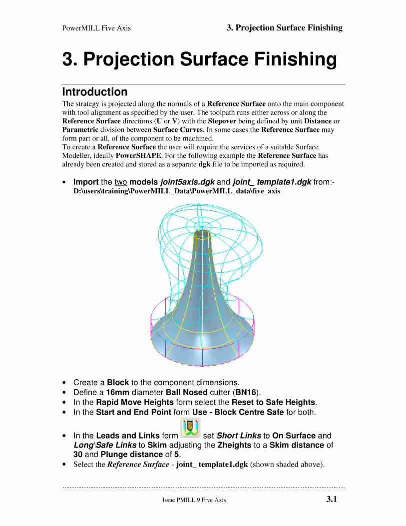
Introduction The strategy is projected along the normals of a Reference Surface onto the main component
with tool alignment as specified by the user. The toolpath runs either across or along the
Reference Surface directions (U or V) with the Stepover being defined by unit Distance or
Parametric division between Surface Curves. In some cases the Reference Surface may
form part or all, of the component to be machined.
To create a Reference Surface the user will require the services of a suitable Surface
Modeller, ideally PowerSHAPE. For the following example the Reference Surface has
already been created and stored as a separate dgk file to be imported as required.
• Import the two models joint5axis.dgk and joint_ template1.dgk from:- D:\users\training\PowerMILL_Data\PowerMILL_data\five_axis
• Create a Block to the component dimensions.
• Define a 16mm diameter Ball Nosed cutter (BN16).
• In the Rapid Move Heights form select the Reset to Safe Heights.
• In the Start and End Point form Use - Block Centre Safe for both.
• In the Leads and Links form set Short Links to On Surface and Long\Safe Links to Skim adjusting the Zheights to a Skim distance of 30 and Plunge distance of 5.
• Select the Reference Surface - joint_ template1.dgk (shown shaded above).
3. Projection Surface Finishing PowerMILL Five Axis
3.2 Issue PMILL 9 Five Axis
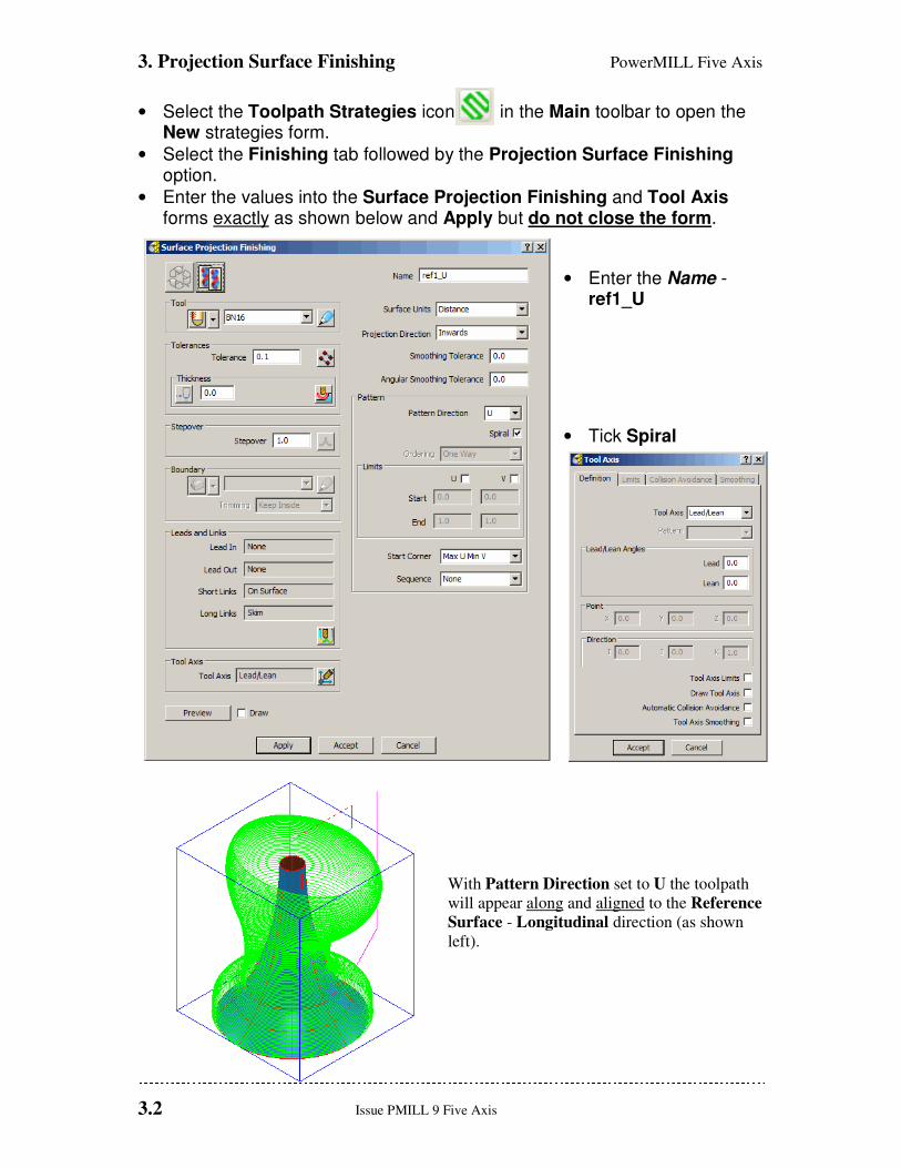
• Select the Toolpath Strategies icon in the Main toolbar to open the New strategies form.
• Select the Finishing tab followed by the Projection Surface Finishing option.
• Enter the values into the Surface Projection Finishing and Tool Axis forms exactly as shown below and Apply but do not close the form.
• Enter the Name - ref1_U
• Tick Spiral
With Pattern Direction set to U the toolpath
will appear along and aligned to the Reference
Surface - Longitudinal direction (as shown
left).
PowerMILL Five Axis 3. Projection Surface Finishing
Issue PMILL 9 Five Axis 3.3
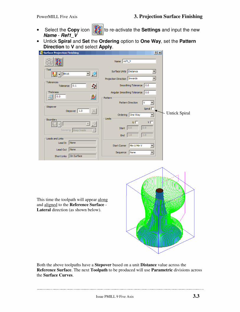
• Select the Copy icon to re-activate the Settings and input the new Name - Ref1_V
• Untick Spiral and Set the Ordering option to One Way, set the Pattern Direction to V and select Apply.
Untick Spiral
This time the toolpath will appear along
and aligned to the Reference Surface -
Lateral direction (as shown below).
Both the above toolpaths have a Stepover based on a unit Distance value across the
Reference Surface. The next Toolpath to be produced will use Parametric divisions across
the Surface Curves.
3. Projection Surface Finishing PowerMILL Five Axis
3.4 Issue PMILL 9 Five Axis
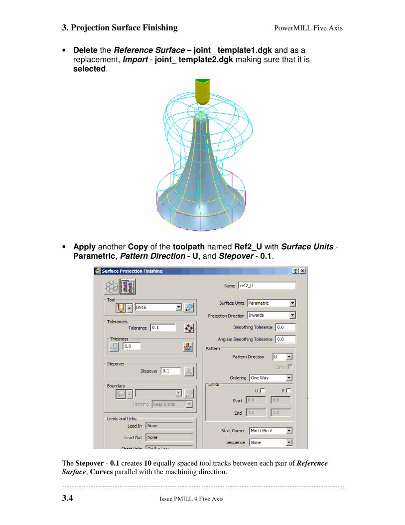
• Delete the Reference Surface – joint_ template1.dgk and as a replacement, Import - joint_ template2.dgk making sure that it is selected.
• Apply another Copy of the toolpath named Ref2_U with Surface Units - Parametric, Pattern Direction - U, and Stepover - 0.1.
The Stepover - 0.1 creates 10 equally spaced tool tracks between each pair of Reference
Surface, Curves parallel with the machining direction.
PowerMILL Five Axis 3. Projection Surface Finishing
Issue PMILL 9 Five Axis 3.5
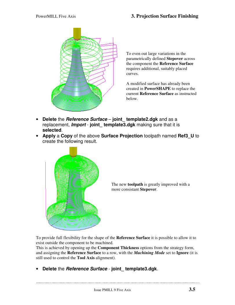
To even out large variations in the
parametrically defined Stepover across
the component the Reference Surface
requires additional, suitably placed
curves.
A modified surface has already been
created in PowerSHAPE to replace the
current Reference Surface as instructed
below.
• Delete the Reference Surface – joint_ template2.dgk and as a replacement, Import - joint_ template3.dgk making sure that it is selected.
• Apply a Copy of the above Surface Projection toolpath named Ref3_U to create the following result.
The new toolpath is greatly improved with a
more consistant Stepover.
To provide full flexibility for the shape of the Reference Surface it is possible to allow it to
exist outside the component to be machined.
This is achieved by opening up the Component Thickness options from the strategy form,
and assigning the Reference Surface to a row, with the Machining Mode set to Ignore (it is
still used to control the Tool Axis alignment).
• Delete the Reference Surface - joint_ template3.dgk.
3. Projection Surface Finishing PowerMILL Five Axis
3.6 Issue PMILL 9 Five Axis
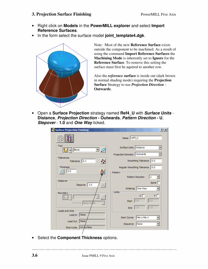
• Right click on Models in the PowerMILL explorer and select Import Reference Surfaces.
• In the form select the surface model joint_template4.dgk. Note: Most of the new Reference Surface exists
outside the component to be machined. As a result of
using the command Import Reference Surfaces the
Machining Mode is inherently set to Ignore for the
Reference Surface. To remove this setting the
surface must first be aquired to another row.
Also the reference surface is inside out (dark brown
in normal shading mode) requiring the Projection
Surface Strategy to use Projection Direction -
Outwards.
• Open a Surface Projection strategy named Ref4_U with Surface Units - Distance, Projection Direction - Outwards, Pattern Direction - U, Stepover - 1.0 and One Way ticked.
• Select the Component Thickness options.
PowerMILL Five Axis 3. Projection Surface Finishing
Issue PMILL 9 Five Axis 3.7
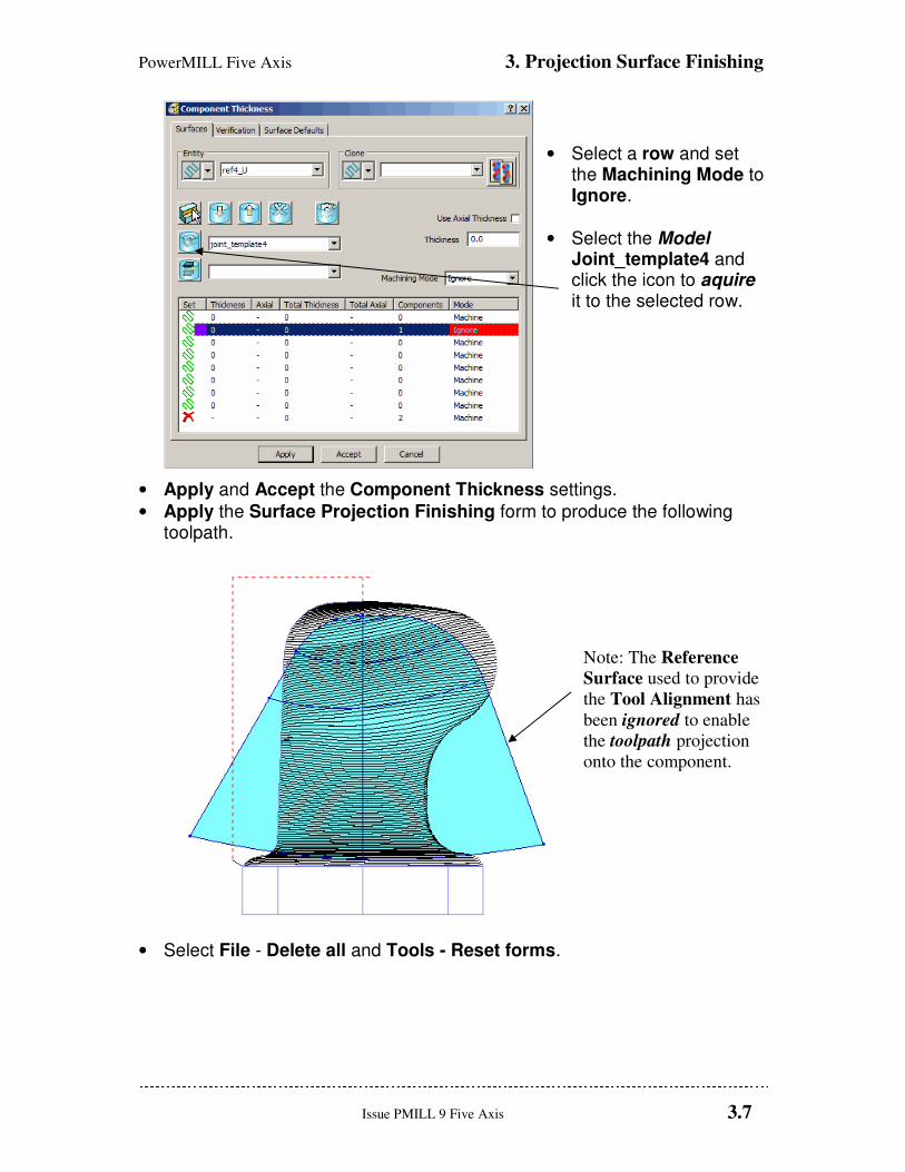
• Select a row and set the Machining Mode to Ignore.
• Select the Model Joint_template4 and click the icon to aquire it to the selected row.
• Apply and Accept the Component Thickness settings.
• Apply the Surface Projection Finishing form to produce the following toolpath.
Note: The Reference
Surface used to provide
the Tool Alignment has
been ignored to enable
the toolpath projection
onto the component.
• Select File - Delete all and Tools - Reset forms.

3. Projection Surface Finishing PowerMILL Five Axis
3.8 Issue PMILL 9 Five Axis
Surface Projection Range. It may be required during some applications, to limit the projection range while applying the
Surface Projection strategy. This situation occurs where the part of the model to be
machined is shielded by other surfaces that are in the way of the defined projection options.
This command is, at present, only available via typed input into the PowerMILL, Command
Window. A more efficient way to control the Projection Range limits is to store the
command lines for different distances in a series of macros, which in turn can be accessed
via the user menu.
• Import the model:-D:\users\training\PowerMILL_data\five_axis\Blade_Sub_Assembly\Blade Inserts
• Create a Block to the component dimensions.
• Define a 6mm diameter Ball Nosed (BN6) cutter of Length 30.
• Create a Shank with Upper Dia 6 Lower Dia 6 Length 20.
• Create a Holder with Upper Dia 20 Lower Dia 16 Length 30
• Add a Holder component Upper Dia 30 Lower Dia 30 Length 20 Overhang 40
• Reset Safe Z and Start Z.
• Set the Start and End Point form for both to Use - Block Centre Safe.
• Set Leads and Links as follows:- Lead in\out Horizontal arc Distance 0 Angle 90 Radius 3 Links Short\Long\Safe Skim
PowerMILL Five Axis 3. Projection Surface Finishing
Issue PMILL 9 Five Axis 3.9
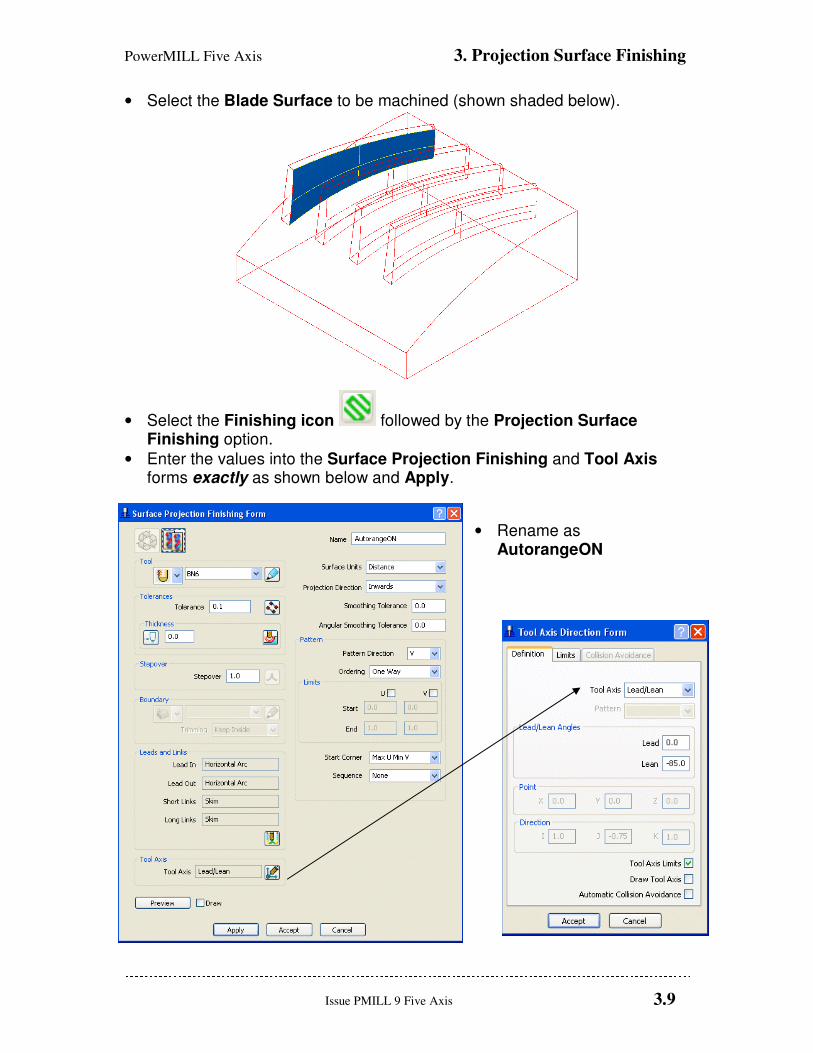
• Select the Blade Surface to be machined (shown shaded below).
• Select the Finishing icon followed by the Projection Surface Finishing option.
• Enter the values into the Surface Projection Finishing and Tool Axis forms exactly as shown below and Apply.
• Rename as AutorangeON
3. Projection Surface Finishing PowerMILL Five Axis
3.10 Issue PMILL 9 Five Axis
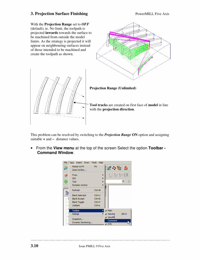
With the Projection Range set to OFF
(default), ie. No limit, the toolpath is
projected inwards towards the surface to
be machined from outside the model
limits. As the strategy is projected it will
appear on neighbouring surfaces instead
of those intended to be machined and
create the toolpath as shown.
Projection Range (Unlimited)
Tool tracks are created on first face of model in line
with the projection direction.
This problem can be resolved by switching to the Projection Range ON option and assigning
suitable + and – distance values.
• From the View menu at the top of the screen Select the option Toolbar -Command Window.
PowerMILL Five Axis 3. Projection Surface Finishing
Issue PMILL 9 Five Axis 3.11
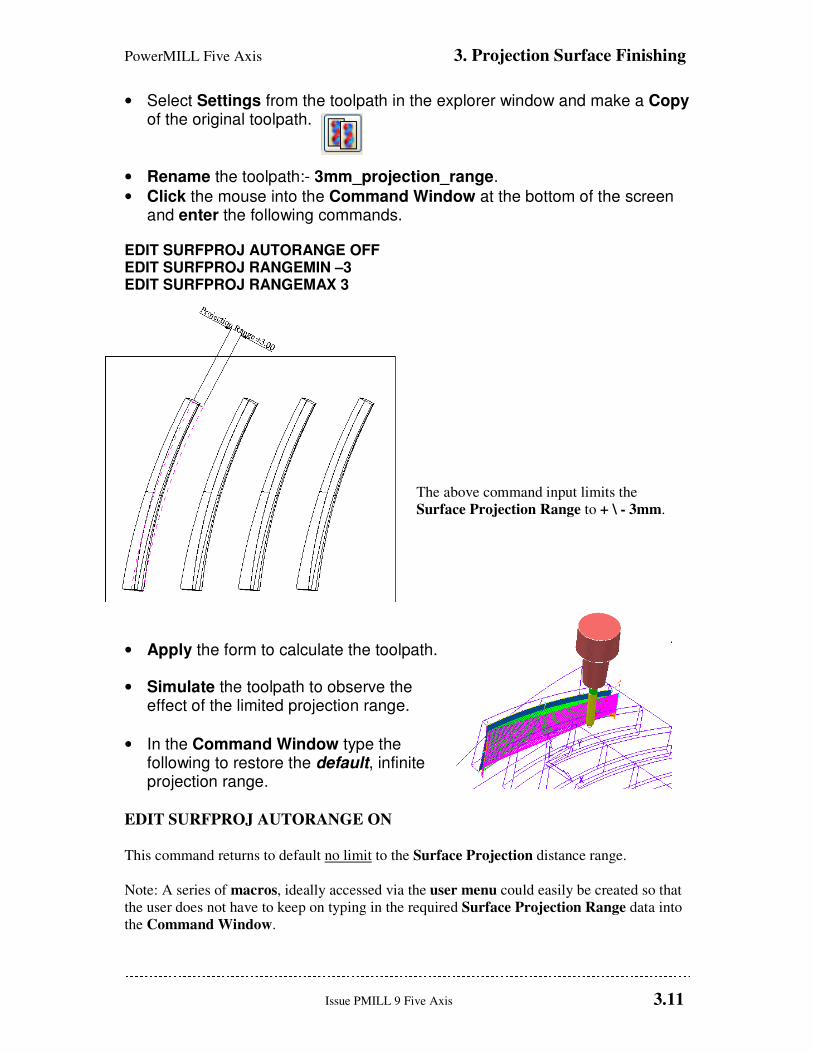
• Select Settings from the toolpath in the explorer window and make a Copy of the original toolpath.
• Rename the toolpath:- 3mm_projection_range.
• Click the mouse into the Command Window at the bottom of the screen and enter the following commands.
EDIT SURFPROJ AUTORANGE OFF EDIT SURFPROJ RANGEMIN –3 EDIT SURFPROJ RANGEMAX 3
The above command input limits the
Surface Projection Range to + \ - 3mm.
• Apply the form to calculate the toolpath.
• Simulate the toolpath to observe the effect of the limited projection range.
• In the Command Window type the following to restore the default, infinite projection range.
EDIT SURFPROJ AUTORANGE ON
This command returns to default no limit to the Surface Projection distance range.
Note: A series of macros, ideally accessed via the user menu could easily be created so that
the user does not have to keep on typing in the required Surface Projection Range data into
the Command Window.

3. Projection Surface Finishing PowerMILL Five Axis
3.12 Issue PMILL 9 Five Axis
PowerMILL Five Axis 4. Pattern Finishing
Issue PMILL 9 Five Axis 4.1
4. Five Axis Pattern Finishing
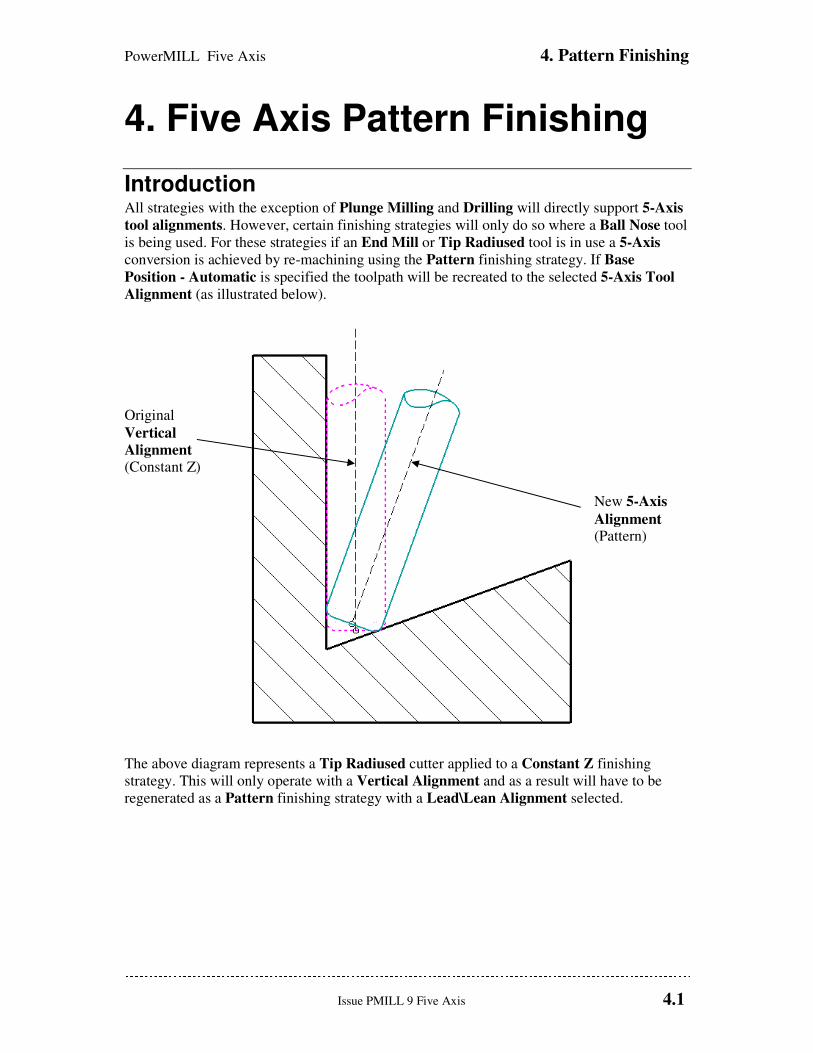
Introduction All strategies with the exception of Plunge Milling and Drilling will directly support 5-Axis
tool alignments. However, certain finishing strategies will only do so where a Ball Nose tool
is being used. For these strategies if an End Mill or Tip Radiused tool is in use a 5-Axis
conversion is achieved by re-machining using the Pattern finishing strategy. If Base
Position - Automatic is specified the toolpath will be recreated to the selected 5-Axis Tool
Alignment (as illustrated below).
Original
Vertical
Alignment (Constant Z)
New 5-Axis
Alignment
(Pattern)
The above diagram represents a Tip Radiused cutter applied to a Constant Z finishing
strategy. This will only operate with a Vertical Alignment and as a result will have to be
regenerated as a Pattern finishing strategy with a Lead\Lean Alignment selected.
4. Pattern Finishing PowerMILL Five Axis
4.2 Issue PMILL 9 Five Axis
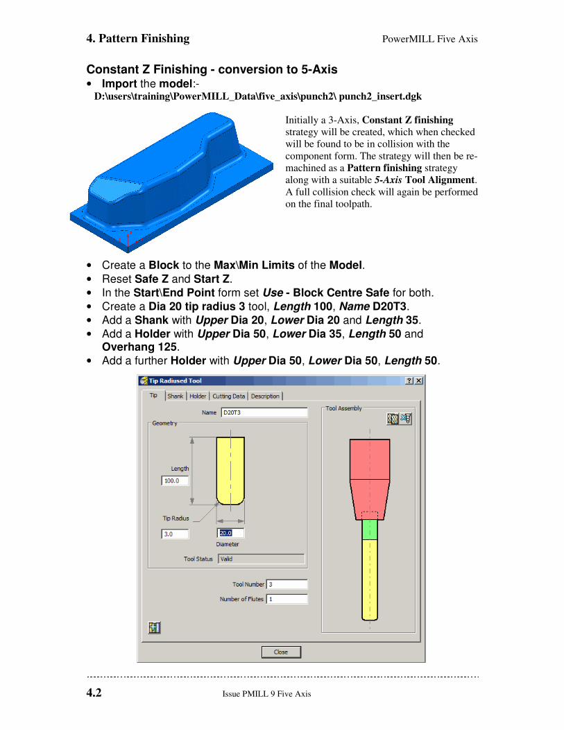
Constant Z Finishing - conversion to 5-Axis • Import the model:- D:\users\training\PowerMILL_Data\five_axis\punch2\ punch2_insert.dgk
Initially a 3-Axis, Constant Z finishing
strategy will be created, which when checked
will be found to be in collision with the
component form. The strategy will then be re-
machined as a Pattern finishing strategy
along with a suitable 5-Axis Tool Alignment.
A full collision check will again be performed
on the final toolpath.
• Create a Block to the Max\Min Limits of the Model.
• Reset Safe Z and Start Z.
• In the Start\End Point form set Use - Block Centre Safe for both.
• Create a Dia 20 tip radius 3 tool, Length 100, Name D20T3.
• Add a Shank with Upper Dia 20, Lower Dia 20 and Length 35.
• Add a Holder with Upper Dia 50, Lower Dia 35, Length 50 and Overhang 125.
• Add a further Holder with Upper Dia 50, Lower Dia 50, Length 50.
PowerMILL Five Axis 4. Pattern Finishing
Issue PMILL 9 Five Axis 4.3
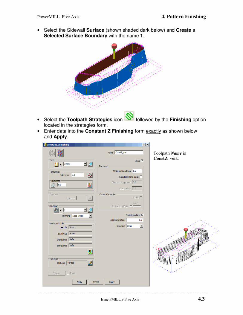
• Select the Sidewall Surface (shown shaded dark below) and Create a Selected Surface Boundary with the name 1.
• Select the Toolpath Strategies icon followed by the Finishing option located in the strategies form.
• Enter data into the Constant Z Finishing form exactly as shown below and Apply.
Toolpath Name is ConstZ_vert.
4. Pattern Finishing PowerMILL Five Axis
4.4 Issue PMILL 9 Five Axis
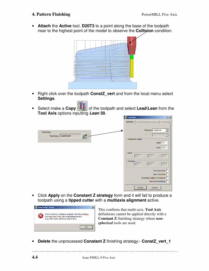
• Attach the Active tool, D20T3 to a point along the base of the toolpath near to the highest point of the model to observe the Collision condition.
• Right click over the toolpath ConstZ_vert and from the local menu select Settings.
• Select make a Copy of the toolpath and select Lead\Lean from the Tool Axis options inputting Lean 30.
• Click Apply on the Constant Z strategy form and it will fail to produce a toolpath using a tipped cutter with a multiaxis alignment active.
This confirms that multi-axis, Tool Axis
definitions cannot be applied directly with a
Constant Z finishing strategy where non-
spherical tools are used.
• Delete the unprocessed Constant Z finishing strategy:- ConstZ_vert_1

PowerMILL Five Axis 4. Pattern Finishing
Issue PMILL 9 Five Axis 4.5
• Select the Toolpath Strategies icon followed by the Finishing option located in the strategies form.
• Enter data into a Pattern Finishing form exactly as shown below and Apply.
The original Constant Z
finishing strategy has been
used as the basis for a
Pattern finishing strategy
with one of 5-Axis tool
alignments applied.
4. Pattern Finishing PowerMILL Five Axis
4.6 Issue PMILL 9 Five Axis
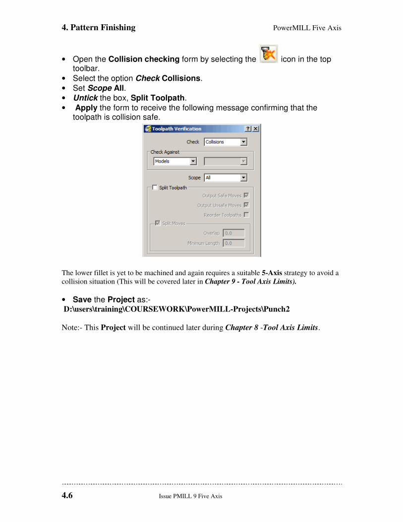
• Open the Collision checking form by selecting the icon in the top toolbar.
• Select the option Check Collisions.
• Set Scope All.
• Untick the box, Split Toolpath.
• Apply the form to receive the following message confirming that the toolpath is collision safe.
The lower fillet is yet to be machined and again requires a suitable 5-Axis strategy to avoid a
collision situation (This will be covered later in Chapter 9 - Tool Axis Limits).
• Save the Project as:- D:\users\training\COURSEWORK\PowerMILL-Projects\Punch2
Note:- This Project will be continued later during Chapter 8 -Tool Axis Limits.
PowerMILL Five Axis 5. Embedded Pattern
Issue PMILL 9 Five Axis 5.1
5. Embedded Pattern Finishing
Introduction
This strategy allows the user to produce an Embedded Pattern Finishing Toolpath using an
Embedded Pattern to define the contact points of the toolpath. An Embedded Pattern is a
curve lying on the model linked to its associated surface (or surfaces).
An Embedded Pattern Finishing toolpath can be used to specify the exact position of
contact point or to use information about the underlying surface (for example surface normal)
to determine the Tool Axis orientation when engraving.
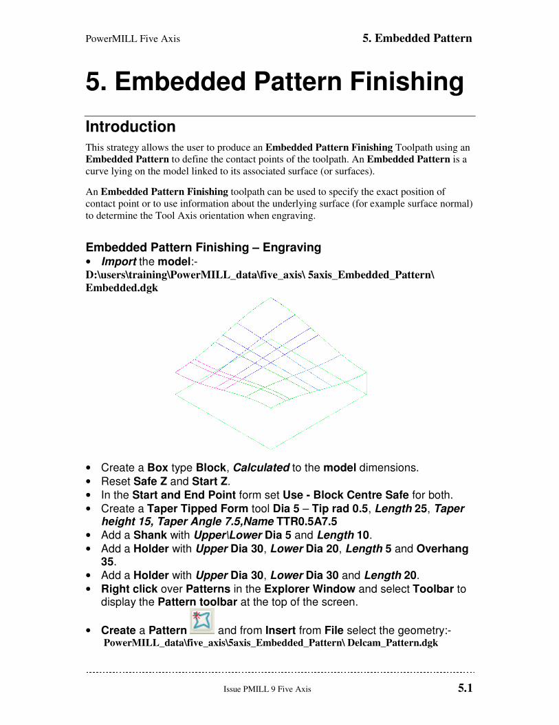
Embedded Pattern Finishing – Engraving • Import the model:- D:\users\training\PowerMILL_data\five_axis\ 5axis_Embedded_Pattern\
Embedded.dgk
• Create a Box type Block, Calculated to the model dimensions.
• Reset Safe Z and Start Z.
• In the Start and End Point form set Use - Block Centre Safe for both.
• Create a Taper Tipped Form tool Dia 5 – Tip rad 0.5, Length 25, Taper height 15, Taper Angle 7.5,Name TTR0.5A7.5
• Add a Shank with Upper\Lower Dia 5 and Length 10.
• Add a Holder with Upper Dia 30, Lower Dia 20, Length 5 and Overhang 35.
• Add a Holder with Upper Dia 30, Lower Dia 30 and Length 20.
• Right click over Patterns in the Explorer Window and select Toolbar to display the Pattern toolbar at the top of the screen.
• Create a Pattern and from Insert from File select the geometry:- PowerMILL_data\five_axis\5axis_Embedded_Pattern\ Delcam_Pattern.dgk

5. Embedded Pattern PowerMILL Five Axis
5.2 Issue PMILL 9 Five Axis
The Pattern contains the Text DELCAM and is positioned above the component surfaces. To
inherit the surface normals for tool alignment it needs to be embedded before it can be used.
• Rename the Pattern ‘Text’.
• Right click the Patterns menu in the explorer window and select Edit – Embed.
The Embedded Pattern form is opened.
• Select Drop as the method and Apply.
PowerMILL Five Axis 5. Embedded Pattern
Issue PMILL 9 Five Axis 5.3
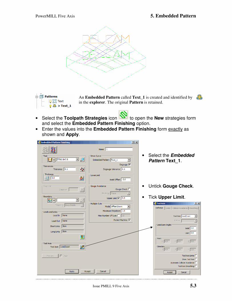
An Embedded Pattern called Text_1 is created and identified by
in the explorer. The original Pattern is retained.
• Select the Toolpath Strategies icon to open the New strategies form and select the Embedded Pattern Finishing option.
• Enter the values into the Embedded Pattern Finishing form exactly as shown and Apply.
• Select the Embedded Pattern Text_1.
• Untick Gouge Check.
• Tick Upper Limit.
5. Embedded Pattern PowerMILL Five Axis
5.4 Issue PMILL 9 Five Axis
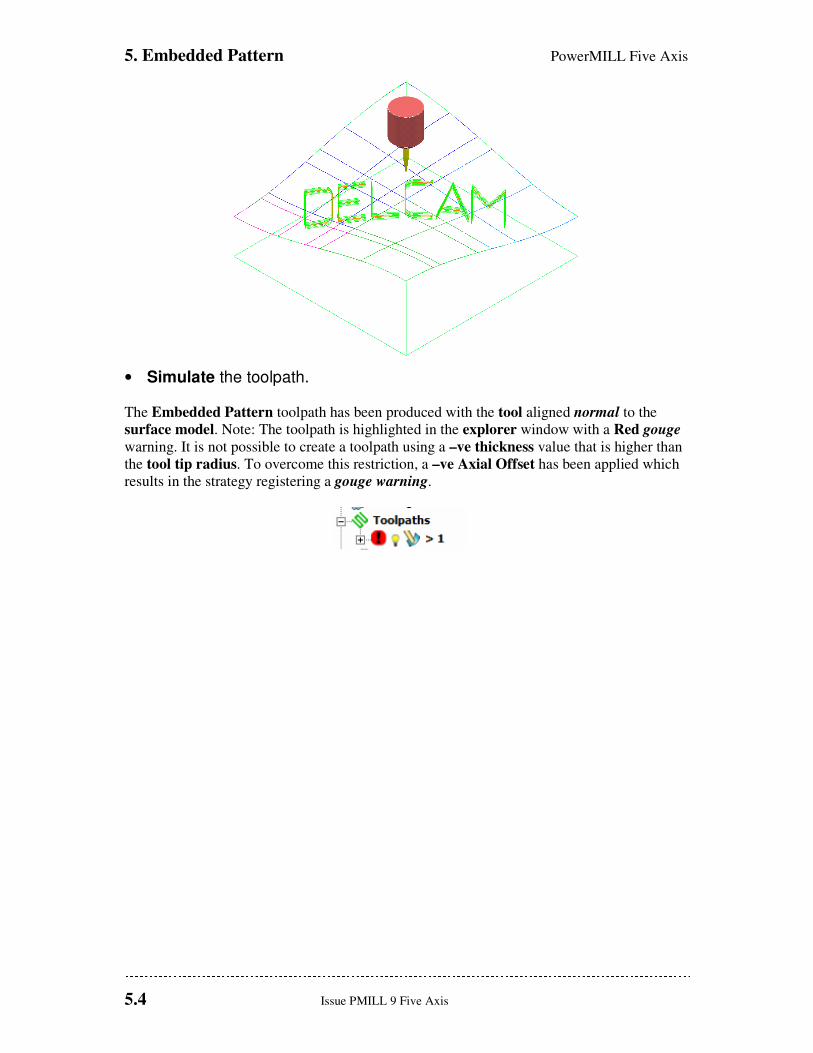
• Simulate the toolpath.
The Embedded Pattern toolpath has been produced with the tool aligned normal to the
surface model. Note: The toolpath is highlighted in the explorer window with a Red gouge
warning. It is not possible to create a toolpath using a –ve thickness value that is higher than
the tool tip radius. To overcome this restriction, a –ve Axial Offset has been applied which
results in the strategy registering a gouge warning.
PowerMILL Five Axis 6. Swarf Finishing
Issue PMILL 9 Five Axis 6.1
6. Five Axis Swarf Machining
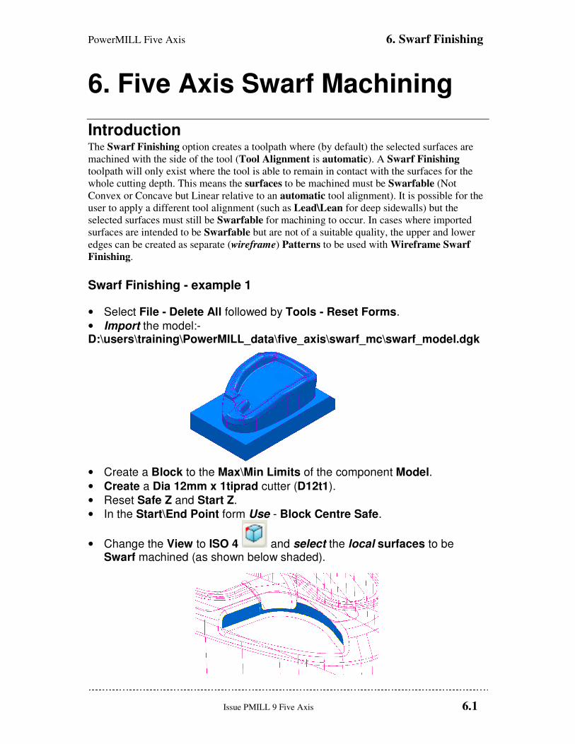
Introduction The Swarf Finishing option creates a toolpath where (by default) the selected surfaces are
machined with the side of the tool (Tool Alignment is automatic). A Swarf Finishing
toolpath will only exist where the tool is able to remain in contact with the surfaces for the
whole cutting depth. This means the surfaces to be machined must be Swarfable (Not
Convex or Concave but Linear relative to an automatic tool alignment). It is possible for the
user to apply a different tool alignment (such as Lead\Lean for deep sidewalls) but the
selected surfaces must still be Swarfable for machining to occur. In cases where imported
surfaces are intended to be Swarfable but are not of a suitable quality, the upper and lower
edges can be created as separate (wireframe) Patterns to be used with Wireframe Swarf
Finishing.
Swarf Finishing - example 1
• Select File - Delete All followed by Tools - Reset Forms.
• Import the model:- D:\users\training\PowerMILL_data\five_axis\swarf_mc\swarf_model.dgk
• Create a Block to the Max\Min Limits of the component Model.
• Create a Dia 12mm x 1tiprad cutter (D12t1).
• Reset Safe Z and Start Z.
• In the Start\End Point form Use - Block Centre Safe.
• Change the View to ISO 4 and select the local surfaces to be Swarf machined (as shown below shaded).
6. Swarf Finishing PowerMILL Five Axis
6.2 Issue PMILL 9 Five Axis
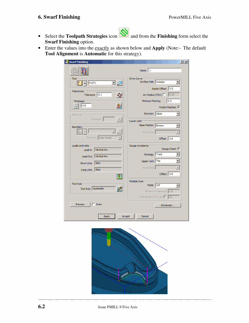
• Select the Toolpath Strategies icon and from the Finishing form select the
Swarf Finishing option.
• Enter the values into the exactly as shown below and Apply (Note:- The default
Tool Alignment is Automatic for this strategy).
PowerMILL Five Axis 6. Swarf Finishing
Issue PMILL 9 Five Axis 6.3
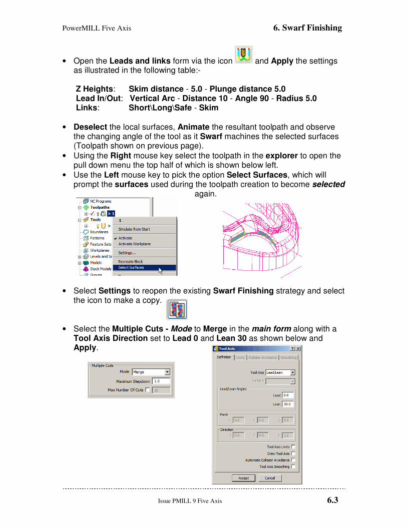
• Open the Leads and links form via the icon and Apply the settings as illustrated in the following table:-
Z Heights: Skim distance - 5.0 - Plunge distance 5.0 Lead In/Out: Vertical Arc - Distance 10 - Angle 90 - Radius 5.0 Links: Short\Long\Safe - Skim
• Deselect the local surfaces, Animate the resultant toolpath and observe the changing angle of the tool as it Swarf machines the selected surfaces (Toolpath shown on previous page).
• Using the Right mouse key select the toolpath in the explorer to open the pull down menu the top half of which is shown below left.
• Use the Left mouse key to pick the option Select Surfaces, which will prompt the surfaces used during the toolpath creation to become selected
again.
• Select Settings to reopen the existing Swarf Finishing strategy and select the icon to make a copy.
• Select the Multiple Cuts - Mode to Merge in the main form along with a Tool Axis Direction set to Lead 0 and Lean 30 as shown below and Apply.
6. Swarf Finishing PowerMILL Five Axis
6.4 Issue PMILL 9 Five Axis
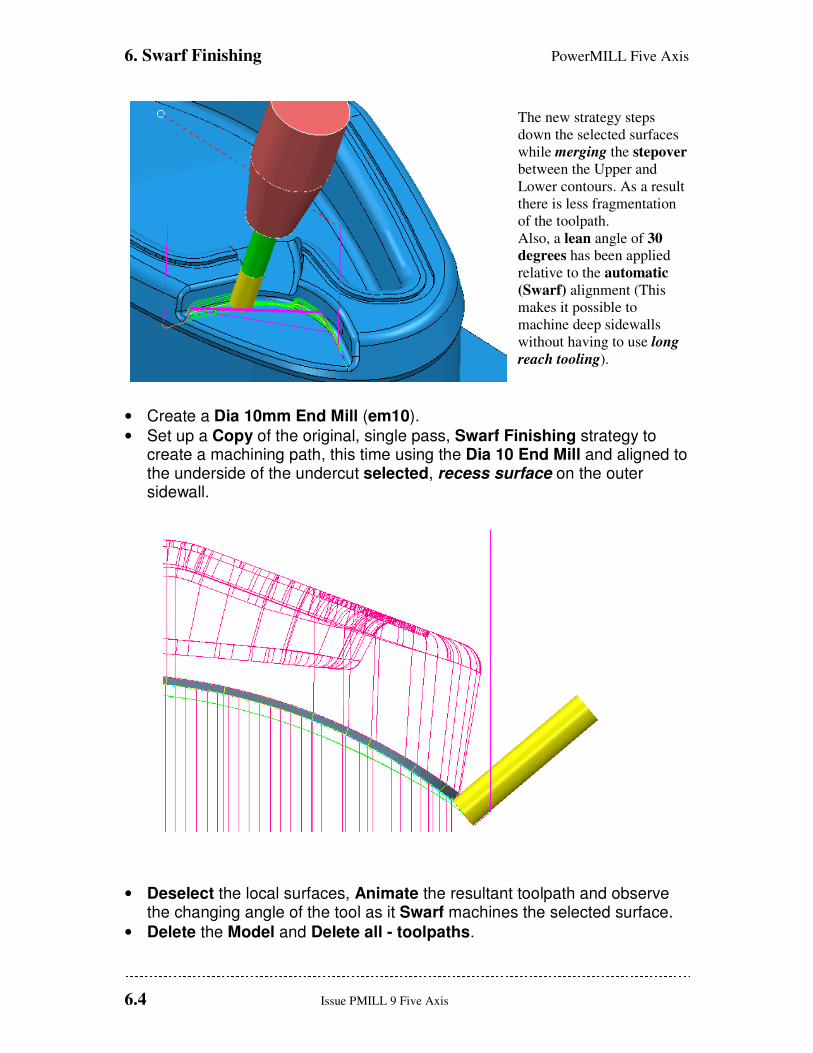
The new strategy steps
down the selected surfaces
while merging the stepover
between the Upper and
Lower contours. As a result
there is less fragmentation
of the toolpath.
Also, a lean angle of 30
degrees has been applied
relative to the automatic
(Swarf) alignment (This
makes it possible to
machine deep sidewalls
without having to use long
reach tooling).
• Create a Dia 10mm End Mill (em10).
• Set up a Copy of the original, single pass, Swarf Finishing strategy to create a machining path, this time using the Dia 10 End Mill and aligned to the underside of the undercut selected, recess surface on the outer sidewall.
• Deselect the local surfaces, Animate the resultant toolpath and observe the changing angle of the tool as it Swarf machines the selected surface.
• Delete the Model and Delete all - toolpaths.
PowerMILL Five Axis 6. Swarf Finishing
Issue PMILL 9 Five Axis 6.5
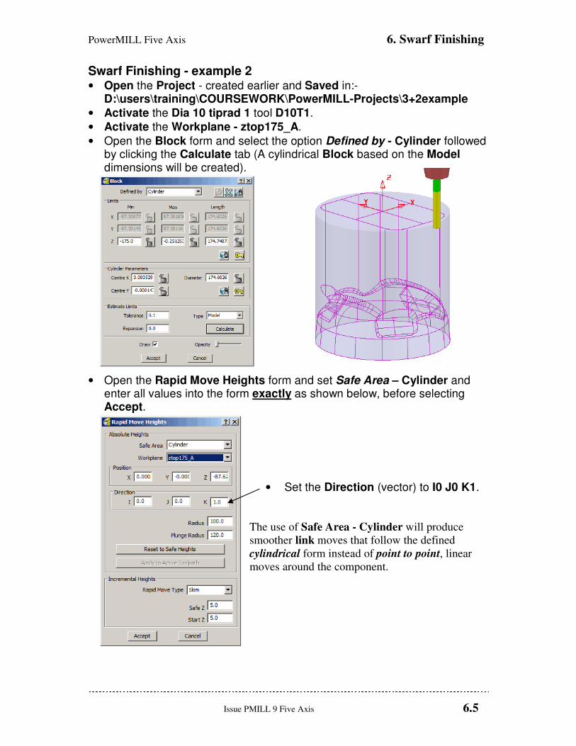
Swarf Finishing - example 2 • Open the Project - created earlier and Saved in:-
D:\users\training\COURSEWORK\PowerMILL-Projects\3+2example
• Activate the Dia 10 tiprad 1 tool D10T1.
• Activate the Workplane - ztop175_A.
• Open the Block form and select the option Defined by - Cylinder followed by clicking the Calculate tab (A cylindrical Block based on the Model dimensions will be created).
• Open the Rapid Move Heights form and set Safe Area – Cylinder and enter all values into the form exactly as shown below, before selecting Accept.
• Set the Direction (vector) to I0 J0 K1.
The use of Safe Area - Cylinder will produce
smoother link moves that follow the defined
cylindrical form instead of point to point, linear
moves around the component.
6. Swarf Finishing PowerMILL Five Axis
6.6 Issue PMILL 9 Five Axis
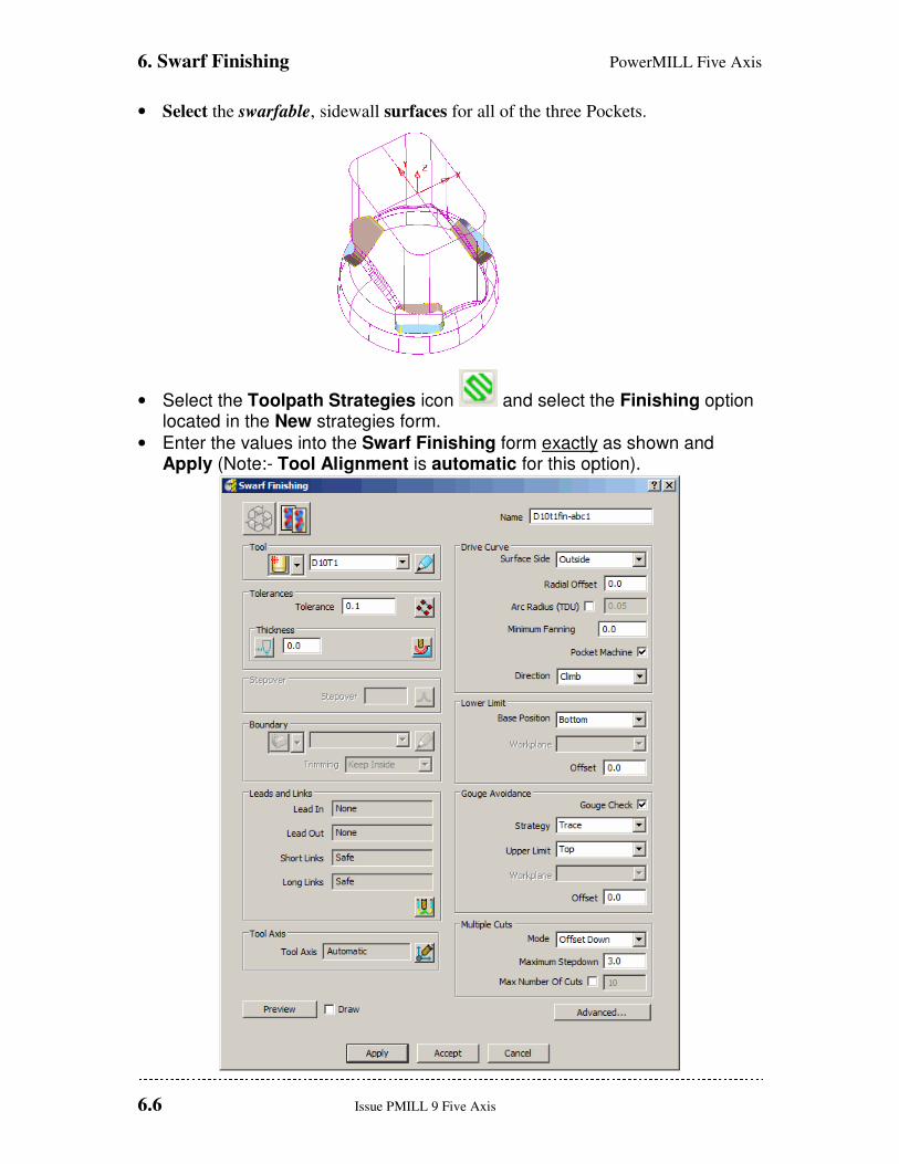
• Select the swarfable, sidewall surfaces for all of the three Pockets.
• Select the Toolpath Strategies icon and select the Finishing option located in the New strategies form.
• Enter the values into the Swarf Finishing form exactly as shown and Apply (Note:- Tool Alignment is automatic for this option).
PowerMILL Five Axis 6. Swarf Finishing
Issue PMILL 9 Five Axis 6.7
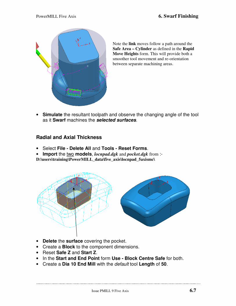
Note the link moves follow a path around the
Safe Area – Cylinder as defined in the Rapid
Move Heights form. This will provide both a
smoother tool movement and re-orientation
between separate machining areas.
• Simulate the resultant toolpath and observe the changing angle of the tool as it Swarf machines the selected surfaces.
Radial and Axial Thickness
• Select File - Delete All and Tools - Reset Forms.
• Import the two models, locnpad.dgk and pocket.dgk from :- D:\users\training\PowerMILL_data\five_axis\locnpad_5axismc\
• Delete the surface covering the pocket.
• Create a Block to the component dimensions.
• Reset Safe Z and Start Z.
• In the Start and End Point form Use - Block Centre Safe for both.
• Create a Dia 10 End Mill with the default tool Length of 50.
6. Swarf Finishing PowerMILL Five Axis
6.8 Issue PMILL 9 Five Axis
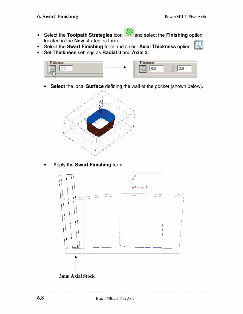
• Select the Toolpath Strategies icon and select the Finishing option located in the New strategies form.
• Select the Swarf Finishing form and select Axial Thickness option.
• Set Thickness settings as Radial 0 and Axial 3.
• Select the local Surface defining the wall of the pocket (shown below).
• Apply the Swarf Finishing form.
3mm Axial Stock
PowerMILL Five Axis 6. Swarf Finishing
Issue PMILL 9 Five Axis 6.9
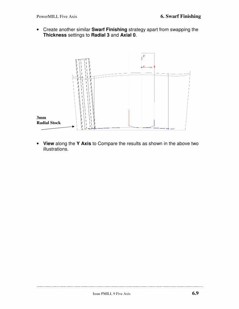
• Create another similar Swarf Finishing strategy apart from swapping the Thickness settings to Radial 3 and Axial 0.
3mm
Radial Stock
• View along the Y Axis to Compare the results as shown in the above two illustrations.

6. Swarf Finishing PowerMILL Five Axis
6.10 Issue PMILL 9 Five Axis
Wireframe Swarf Finishing
It is not uncommon for an imported model to be of a poor standard with such problem areas
as small gaps, mismatching surfaces, and intended planer, surfaces that bulge slightly. One or
more of these can create a range of problems in creating a high quality finish during the
machining process. In some cases a poor quality model will cause a particular machining
strategy to be unusable resulting in the user having to find an alternative method.
The model used in the following example contains a pocket in which part of the sidewall is
unswarfable due to being slightly convex between the top and bottom edges.
• From the main pulldown menus select File - Delete all.
• Import the models Wfrm-Swarf.dgk from the local directory: D:\users\training\PowerMILL_data \five_axis\Swarf_mc.
• Activate the Workplane - Datum.
• Create a Block to the Max\Min Limits of the component Model.
• Create a Dia 5mm End Mill cutter (EM5) using the following dimensions for the Tool, Shank and Holder:-
Tool Dia 5 Length 35 Shank Lower Dia 5 Upper Dia 5 Length 15 Holder-1 Lower Dia 15 Upper Dia 25 Length 15 Holder-2 Lower Dia 25 Upper Dia 25 Length 15 Overhang 50
• Reset Safe Z and Start Z.
• In the Start and End Point form Use - Block Centre Safe for both.
PowerMILL Five Axis 6. Swarf Finishing
Issue PMILL 9 Five Axis 6.11
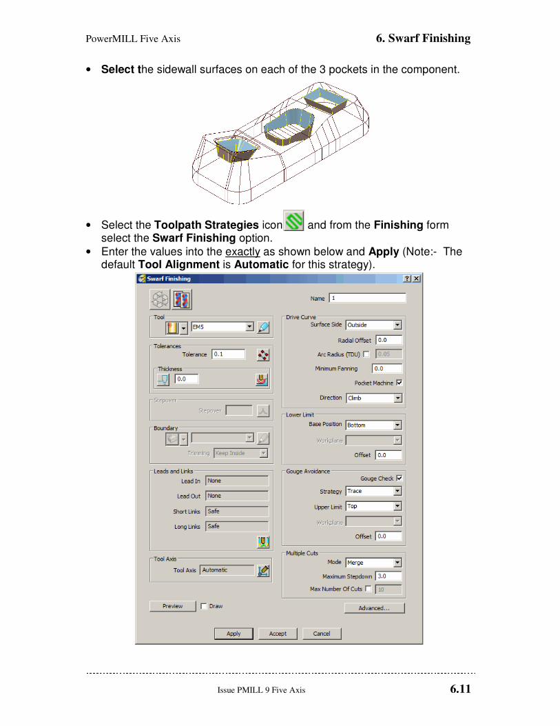
• Select the sidewall surfaces on each of the 3 pockets in the component.
• Select the Toolpath Strategies icon and from the Finishing form select the Swarf Finishing option.
• Enter the values into the exactly as shown below and Apply (Note:- The default Tool Alignment is Automatic for this strategy).
6. Swarf Finishing PowerMILL Five Axis
6.12 Issue PMILL 9 Five Axis
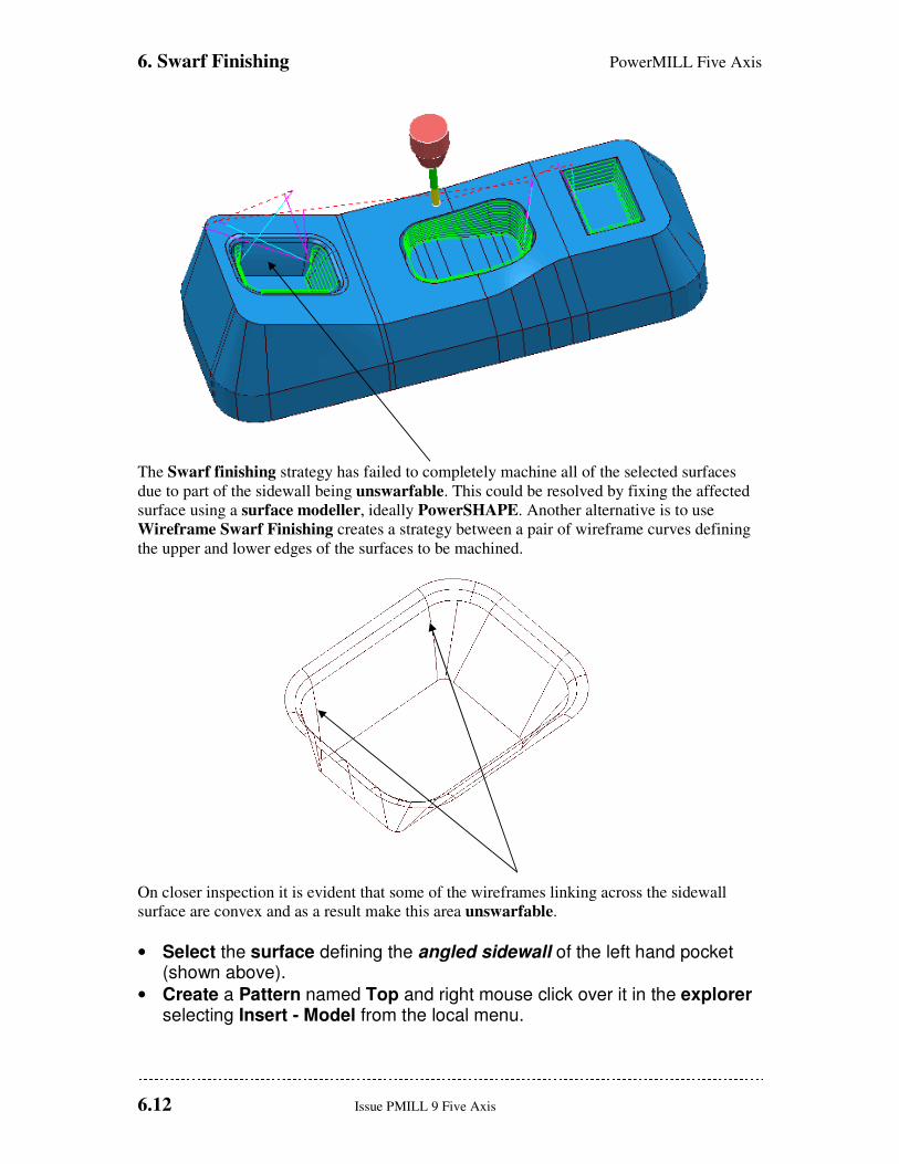
The Swarf finishing strategy has failed to completely machine all of the selected surfaces
due to part of the sidewall being unswarfable. This could be resolved by fixing the affected
surface using a surface modeller, ideally PowerSHAPE. Another alternative is to use
Wireframe Swarf Finishing creates a strategy between a pair of wireframe curves defining
the upper and lower edges of the surfaces to be machined.
On closer inspection it is evident that some of the wireframes linking across the sidewall
surface are convex and as a result make this area unswarfable.
• Select the surface defining the angled sidewall of the left hand pocket (shown above).
• Create a Pattern named Top and right mouse click over it in the explorer selecting Insert - Model from the local menu.
PowerMILL Five Axis 6. Swarf Finishing
Issue PMILL 9 Five Axis 6.13
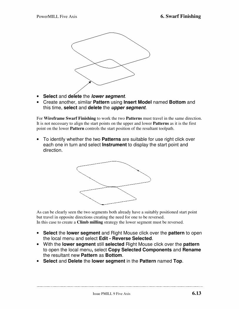
• Select and delete the lower segment.
• Create another, similar Pattern using Insert Model named Bottom and this time, select and delete the upper segment.
For Wireframe Swarf Finishing to work the two Patterns must travel in the same direction.
It is not necessary to align the start points on the upper and lower Patterns as it is the first
point on the lower Pattern controls the start position of the resultant toolpath.
• To identify whether the two Patterns are suitable for use right click over each one in turn and select Instrument to display the start point and direction.
As can be clearly seen the two segments both already have a suitably positioned start point
but travel in opposite directions creating the need for one to be reversed.
In this case to create a Climb milling strategy the lower segment must be reversed.
• Select the lower segment and Right Mouse click over the pattern to open the local menu and select Edit - Reverse Selected.
• With the lower segment still selected Right Mouse click over the pattern to open the local menu, select Copy Selected Components and Rename the resultant new Pattern as Bottom.
• Select and Delete the lower segment in the Pattern named Top.
6. Swarf Finishing PowerMILL Five Axis
6.14 Issue PMILL 9 Five Axis
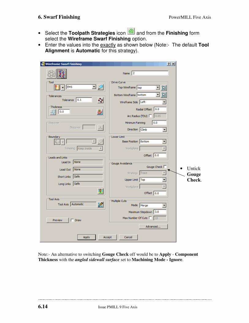
• Select the Toolpath Strategies icon and from the Finishing form select the Wireframe Swarf Finishing option.
• Enter the values into the exactly as shown below (Note:- The default Tool Alignment is Automatic for this strategy).
• Untick
Gouge
Check.
Note:- An alternative to switching Gouge Check off would be to Apply - Component
Thickness with the angled sidewall surface set to Machining Mode - Ignore.
PowerMILL Five Axis 6. Swarf Finishing
Issue PMILL 9 Five Axis 6.15
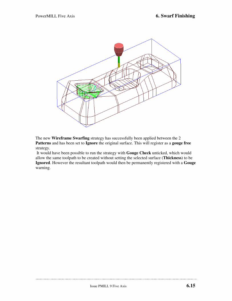
The new Wireframe Swarfing strategy has successfully been applied between the 2
Patterns and has been set to Ignore the original surface. This will register as a gouge free
strategy.
It would have been possible to run the strategy with Gouge Check unticked, which would
allow the same toolpath to be created without setting the selected surface (Thickness) to be
Ignored. However the resultant toolpath would then be permanently registered with a Gouge
warning.

6. Swarf Finishing PowerMILL Five Axis
6.16 Issue PMILL 9 Five Axis
PowerMILLFive Axis 7. Rotary Machining
Issue PMILL 9 Five Axis 7.1
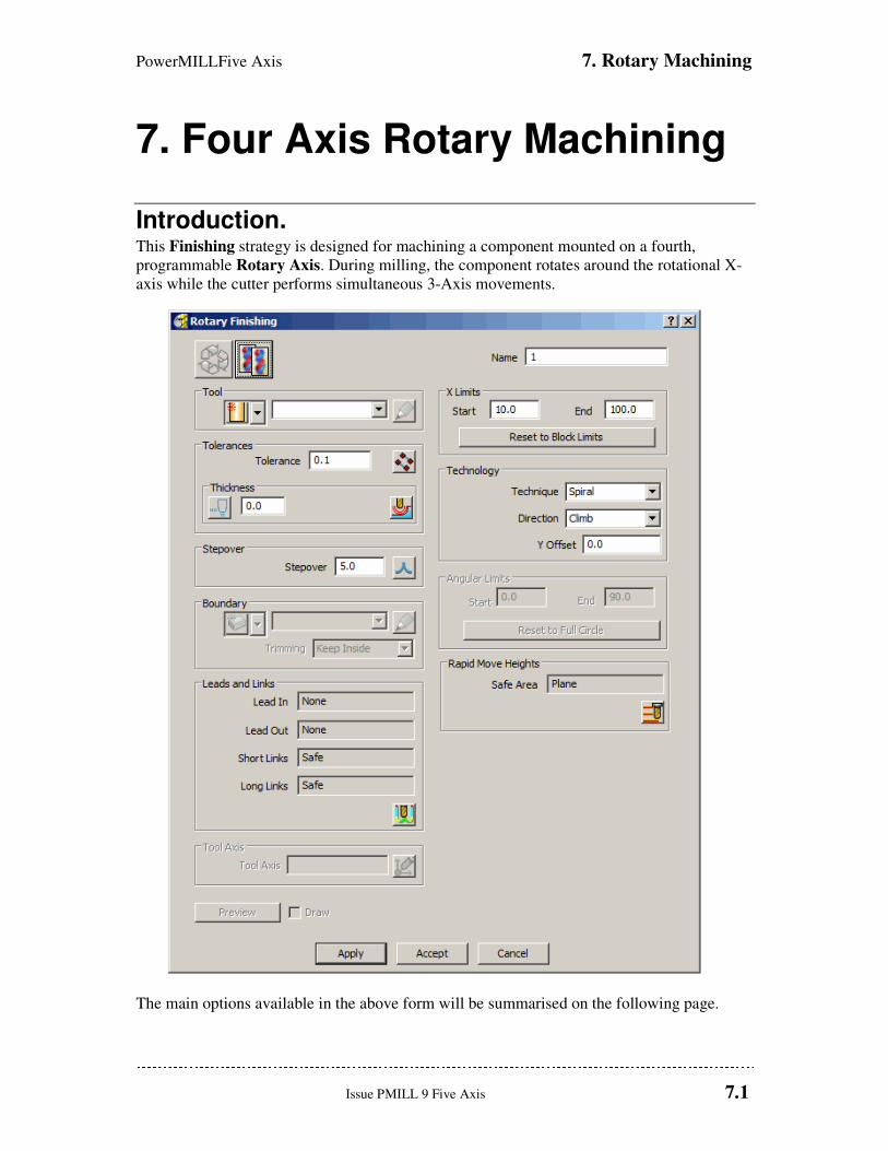
7. Four Axis Rotary Machining
Introduction. This Finishing strategy is designed for machining a component mounted on a fourth,
programmable Rotary Axis. During milling, the component rotates around the rotational X-
axis while the cutter performs simultaneous 3-Axis movements.
The main options available in the above form will be summarised on the following page.
7. Rotary Machining PowerMILL Five Axis
7.2 Issue PMILL 9 Five Axis
X Limits The X Limits define the absolute limits of the finishing path along the rotational, X-axis.
These can be manually defined, or automatically set to the limits of the block.
Technique This enables the cutting method to be specified for rotary milling either Circular, Line, or
Spiral.
Direction This option determines whether Climb, Conventional, or Any milling directions are used.
Stepover In the case of Circular and Spiral this is defined as the pitch for each programmed
revolution of the component. For Line this is defined as the angular, stepover between
adjacent tool tracks.
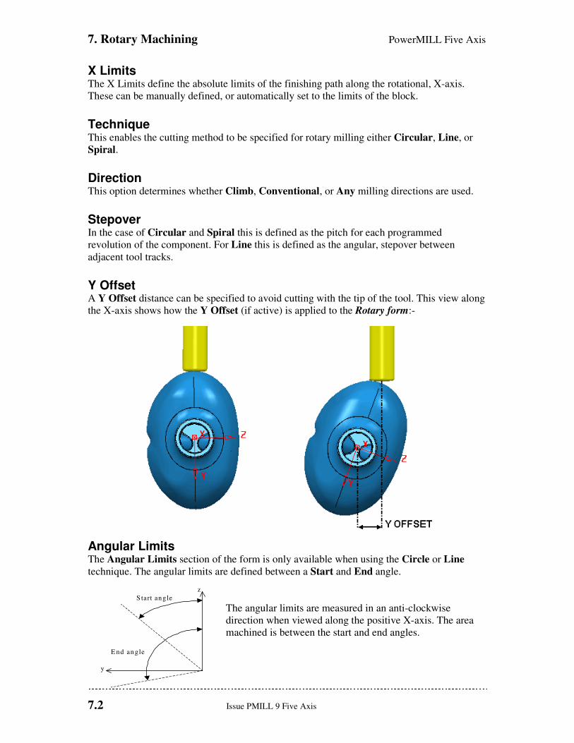
Y Offset A Y Offset distance can be specified to avoid cutting with the tip of the tool. This view along
the X-axis shows how the Y Offset (if active) is applied to the Rotary form:-
Angular Limits The Angular Limits section of the form is only available when using the Circle or Line
technique. The angular limits are defined between a Start and End angle.
The angular limits are measured in an anti-clockwise
direction when viewed along the positive X-axis. The area
machined is between the start and end angles.
S tart angle
E nd angle
y
z
PowerMILLFive Axis 7. Rotary Machining
Issue PMILL 9 Five Axis 7.3
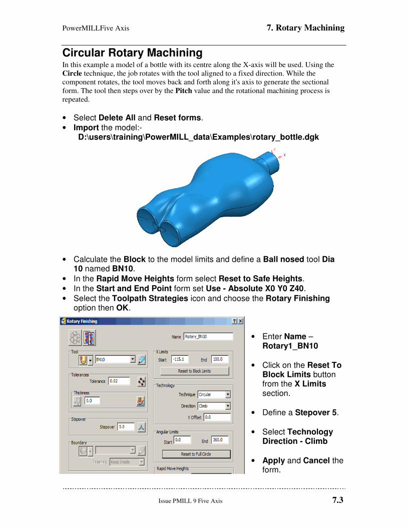
Circular Rotary Machining In this example a model of a bottle with its centre along the X-axis will be used. Using the
Circle technique, the job rotates with the tool aligned to a fixed direction. While the
component rotates, the tool moves back and forth along it's axis to generate the sectional
form. The tool then steps over by the Pitch value and the rotational machining process is
repeated.
• Select Delete All and Reset forms.
• Import the model:- D:\users\training\PowerMILL_data\Examples\rotary_bottle.dgk
• Calculate the Block to the model limits and define a Ball nosed tool Dia 10 named BN10.
• In the Rapid Move Heights form select Reset to Safe Heights.
• In the Start and End Point form set Use - Absolute X0 Y0 Z40.
• Select the Toolpath Strategies icon and choose the Rotary Finishing option then OK.
• Enter Name – Rotary1_BN10
• Click on the Reset To Block Limits button from the X Limits section.
• Define a Stepover 5.
• Select Technology Direction - Climb
• Apply and Cancel the form.
7. Rotary Machining PowerMILL Five Axis
7.4 Issue PMILL 9 Five Axis
• Right click over the toolpath Rotary1_BN10 in the explorer and select Simulate from Start to open the Simulation Toolbar.
• On the Simulation Toolbar select the Tool view point icon .
• Select the Play button on the Simulation toolbar .
By applying Tool view point
the rotation of the
component is simulated (As
if viewing the actual
machine tool).
In the above example each section is machined in the same Climb milling direction. The
entire length of the job is machined since the X Limits are set to the block limits. Selecting
Conventional will produce tool tracks travelling in the reverse direction and Any will
produce alternate Climb and Conventional tool tracks along the job.
• Recycle the toolpath, select Any from the Technology Direction pull-down button and click on Apply then Cancel.
• Simulate the toolpath as before to observe how the tool reverses direction with every new section machined.
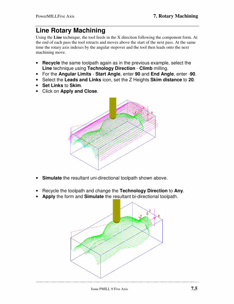
PowerMILLFive Axis 7. Rotary Machining
Issue PMILL 9 Five Axis 7.5
Line Rotary Machining Using the Line technique, the tool feeds in the X direction following the component form. At
the end of each pass the tool retracts and moves above the start of the next pass. At the same
time the rotary axis indexes by the angular stepover and the tool then leads onto the next
machining move.
• Recycle the same toolpath again as in the previous example, select the Line technique using Technology Direction - Climb milling.
• For the Angular Limits - Start Angle, enter 90 and End Angle, enter -90.
• Select the Leads and Links icon, set the Z Heights Skim distance to 20.
• Set Links to Skim.
• Click on Apply and Close.
• Simulate the resultant uni-directional toolpath shown above.
• Recycle the toolpath and change the Technology Direction to Any.
• Apply the form and Simulate the resultant bi-directional toolpath.
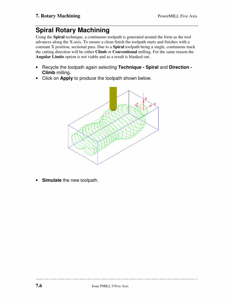
7. Rotary Machining PowerMILL Five Axis
7.6 Issue PMILL 9 Five Axis
Spiral Rotary Machining Using the Spiral technique, a continuous toolpath is generated around the form as the tool
advances along the X-axis. To ensure a clean finish the toolpath starts and finishes with a
constant X position, sectional pass. Due to a Spiral toolpath being a single, continuous track
the cutting direction will be either Climb or Conventional milling. For the same reason the
Angular Limits option is not viable and as a result is blanked out.
• Recycle the toolpath again selecting Technique - Spiral and Direction - Climb milling.
• Click on Apply to produce the toolpath shown below.
• Simulate the new toolpath.
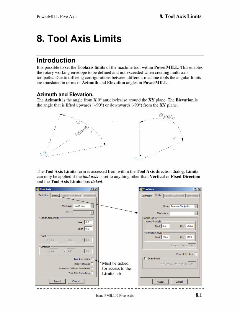
PowerMILL Five Axis 8. Tool Axis Limits
Issue PMILL 9 Five Axis 8.1
8. Tool Axis Limits
Introduction It is possible to set the Toolaxis limits of the machine tool within PowerMILL. This enables
the rotary working envelope to be defined and not exceeded when creating multi-axis
toolpaths. Due to differing configurations between different machine tools the angular limits
are translated in terms of Azimuth and Elevation angles in PowerMILL.
Azimuth and Elevation. The Azimuth is the angle from X 0° anticlockwise around the XY plane. The Elevation is
the angle that is lifted upwards (+90°) or downwards (-90°) from the XY plane.
.
The Tool Axis Limits form is accessed from within the Tool Axis direction dialog. Limits
can only be applied if the tool axis is set to anything other than Vertical or Fixed Direction
and the Tool Axis Limits box ticked.
Must be ticked
for access to the
Limits tab
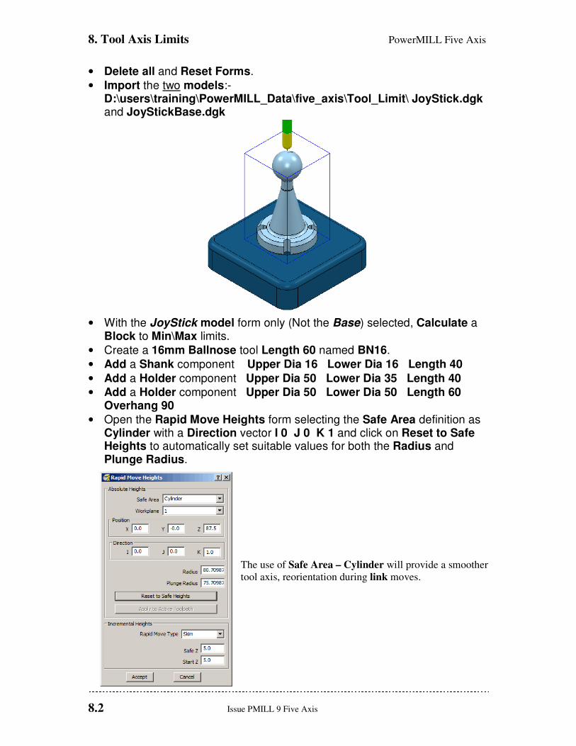
8. Tool Axis Limits PowerMILL Five Axis
8.2 Issue PMILL 9 Five Axis
• Delete all and Reset Forms.
• Import the two models:- D:\users\training\PowerMILL_Data\five_axis\Tool_Limit\ JoyStick.dgk and JoyStickBase.dgk
• With the JoyStick model form only (Not the Base) selected, Calculate a Block to Min\Max limits.
• Create a 16mm Ballnose tool Length 60 named BN16.
• Add a Shank component Upper Dia 16 Lower Dia 16 Length 40
• Add a Holder component Upper Dia 50 Lower Dia 35 Length 40
• Add a Holder component Upper Dia 50 Lower Dia 50 Length 60 Overhang 90
• Open the Rapid Move Heights form selecting the Safe Area definition as Cylinder with a Direction vector I 0 J 0 K 1 and click on Reset to Safe Heights to automatically set suitable values for both the Radius and Plunge Radius.
The use of Safe Area – Cylinder will provide a smoother
tool axis, reorientation during link moves.

PowerMILL Five Axis 8. Tool Axis Limits
Issue PMILL 9 Five Axis 8.3
• Set both Start and End Point to Use - Block Centre Safe.
• Set Leads and Links as follows:-
Lead In\Out --None
Extensions --None
Links Short --On Surface
Long --Skim
Default --Skim
• Select the Reference Surface (shown shaded ).
• From the Toolpath Strategies icon select Projection Surface Finishing option from the Finishing form.
• Rename the Toolpath BN16-LimitsUnset and enter the values into the Surface Projection Finishing and Tool Axis forms exactly as shown below (Do Not Apply the form yet!).
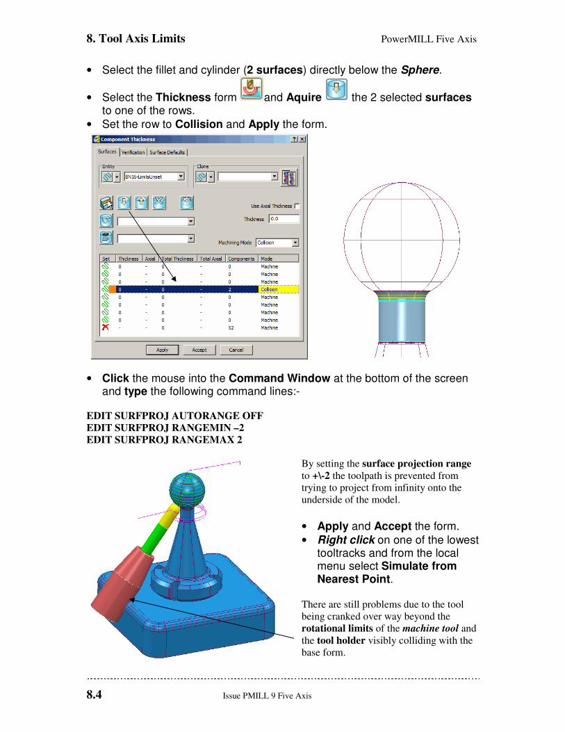
8. Tool Axis Limits PowerMILL Five Axis
8.4 Issue PMILL 9 Five Axis
• Select the fillet and cylinder (2 surfaces) directly below the Sphere.
• Select the Thickness form and Aquire the 2 selected surfaces to one of the rows.
• Set the row to Collision and Apply the form.
• Click the mouse into the Command Window at the bottom of the screen and type the following command lines:-
EDIT SURFPROJ AUTORANGE OFF
EDIT SURFPROJ RANGEMIN –2
EDIT SURFPROJ RANGEMAX 2
By setting the surface projection range
to +\-2 the toolpath is prevented from
trying to project from infinity onto the
underside of the model.
• Apply and Accept the form.
• Right click on one of the lowest tooltracks and from the local menu select Simulate from Nearest Point.
There are still problems due to the tool
being cranked over way beyond the
rotational limits of the machine tool and
the tool holder visibly colliding with the
base form.
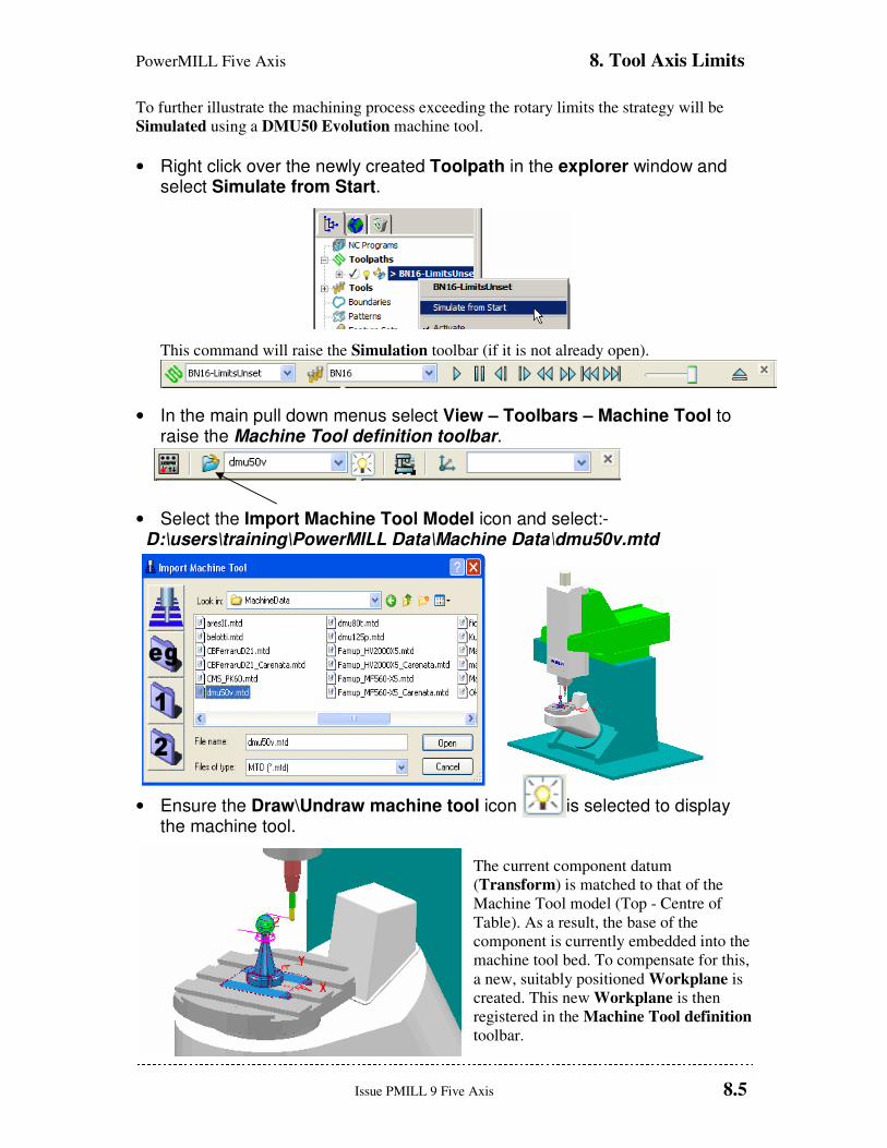
PowerMILL Five Axis 8. Tool Axis Limits
Issue PMILL 9 Five Axis 8.5
To further illustrate the machining process exceeding the rotary limits the strategy will be
Simulated using a DMU50 Evolution machine tool.
• Right click over the newly created Toolpath in the explorer window and select Simulate from Start.
This command will raise the Simulation toolbar (if it is not already open).
• In the main pull down menus select View – Toolbars – Machine Tool to raise the Machine Tool definition toolbar.
• Select the Import Machine Tool Model icon and select:- D:\users\training\PowerMILL Data\Machine Data\dmu50v.mtd
• Ensure the Draw\Undraw machine tool icon is selected to display the machine tool.
The current component datum
(Transform) is matched to that of the
Machine Tool model (Top - Centre of
Table). As a result, the base of the
component is currently embedded into the
machine tool bed. To compensate for this,
a new, suitably positioned Workplane is
created. This new Workplane is then
registered in the Machine Tool definition
toolbar.
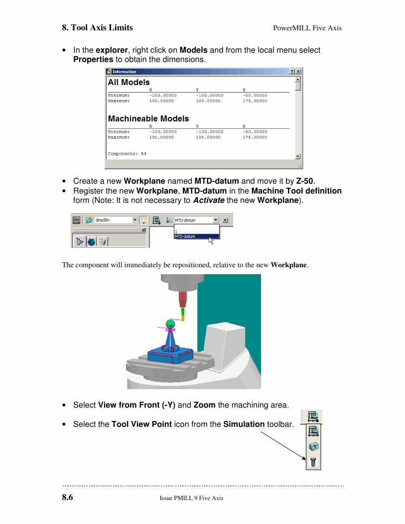
8. Tool Axis Limits PowerMILL Five Axis
8.6 Issue PMILL 9 Five Axis
• In the explorer, right click on Models and from the local menu select Properties to obtain the dimensions.
• Create a new Workplane named MTD-datum and move it by Z-50.
• Register the new Workplane, MTD-datum in the Machine Tool definition form (Note: It is not necessary to Activate the new Workplane).
The component will immediately be repositioned, relative to the new Workplane.
• Select View from Front (-Y) and Zoom the machining area.
• Select the Tool View Point icon from the Simulation toolbar.
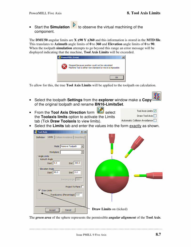
PowerMILL Five Axis 8. Tool Axis Limits
Issue PMILL 9 Five Axis 8.7
• Start the Simulation to observe the virtual machining of the component.
The DMU50 angular limits are X ±90 Y ±360 and this information is stored in the MTD file.
This translates to Azimuth angle limits of 0 to 360 and Elevation angle limits of 0 to 90.
When the toolpath simulation attempts to go beyond this range an error message will be
displayed indicating that the machine, Tool Axis Limits will be exceeded.
To allow for this, the true Tool Axis Limits will be applied to the toolpath on calculation.
• Select the toolpath Settings from the explorer window make a Copy of the original toolpath and rename BN16-LimitsSet.
• From the Tool Axis Direction form select the Toolaxis limits option to activate the Limits tab (Tick Draw Toolaxis to view limits).
• Select the Limits tab and enter the values into the form exactly as shown.
Draw Limits on (ticked)
The green area of the sphere represents the permissible angular alignment of the Tool Axis.
8. Tool Axis Limits PowerMILL Five Axis
8.8 Issue PMILL 9 Five Axis
• Accept the Tool Axis Direction form.
• With the same Reference Surface selected Apply and Accept the form.
• Right click over the Toolpath, BN16-LimitsSet in the explorer window and select Simulate from Start.
• Simulate the Toolpath.
With Mode set to Remove
Toolpath in the Limits form, only
the portion of the surface within the
rotary Tool Axis Limit range is
machined.
• Right mouse click on the toolpath, BN16-LimitsSet and Select Settings to access the Surface Projection Finishing form.
• Select recycle and from the Tool Axis Direction form select the Limits tab and enter the values into the form exactly as shown below.
PowerMILL Five Axis 8. Tool Axis Limits
Issue PMILL 9 Five Axis 8.9
• Accept the Tool Axis Direction form.
• With the original surface selected Apply and Accept the toolpath.
• Right click over the Toolpath 10bnLimitsSet in the explorer window and select Attach Active Tool to Start.
• Simulate the Toolpath.
With Mode set to Move Toolaxis in the Limits form, the surface is fully machined with the
Tool Axis becoming fixed when it reaches the maximum, Tool Axis Limit.

8. Tool Axis Limits PowerMILL Five Axis
8.10 Issue PMILL 9 Five Axis
Defining Limits for a Multi-Axis Machine The Tool Axis Limits option allows the user to control the angular limits of a tool while
creating a multi-axis toolpath. The specified limits will differ in format depending on the type
of rotary axis configuration. As a result they will have to be translated as universal Azimuth
and Elevation angles to be compatible with PowerMILL.
The configuration of the rotary axes varies widely, however the differences between many of
these are relatively minor and there are really only three fundamentally different machine
configurations:
Table – Table Both rotary axes move the table.
Head – Head Both rotary axes move the head.
Head – Table One rotary axis moves the head, the other moves the table.
The next examples will show how to transpose angular limits of a machine tool into Azimuth
and Elevation angles.
• Delete all and Reset Forms.
• Select the Tool Axis icon from the main PowerMILL toolbar.
• Define Tool Axis as Lead\Lean and set Lead\Lean angles to zero.
• Select the Toolaxis Limits option to activate the Limits tab.
• Open the Limits tab.
• Select the Draw Limits option from the form.
• Select view Iso 1.
With the Draw Limits option selected a
sphere will be displayed in the graphics
window representing the angular machining
limits available.
Green indicates a machinable portion and Red
a non-machinable portion. With the default
settings selected the total machining range is
covered so the whole sphere will be Green.
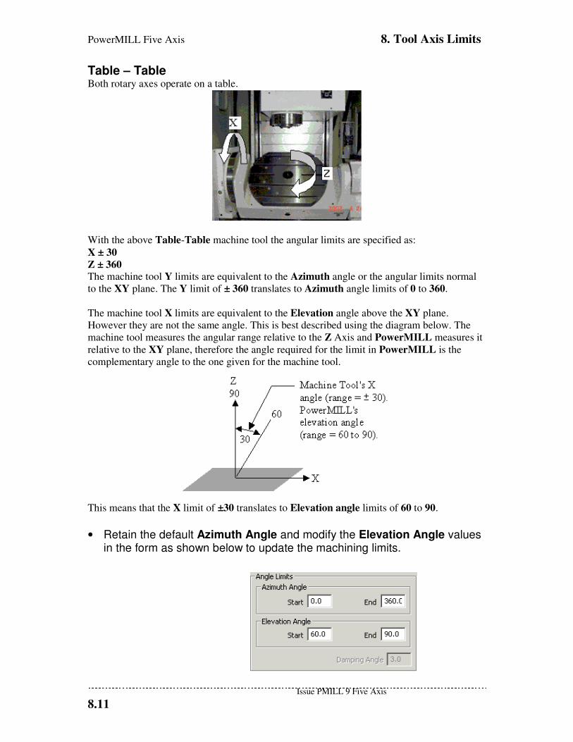
PowerMILL Five Axis 8. Tool Axis Limits
Issue PMILL 9 Five Axis
8.11
Table – Table Both rotary axes operate on a table.
With the above Table-Table machine tool the angular limits are specified as:
X ± 30
Z ± 360
The machine tool Y limits are equivalent to the Azimuth angle or the angular limits normal
to the XY plane. The Y limit of ± 360 translates to Azimuth angle limits of 0 to 360.
The machine tool X limits are equivalent to the Elevation angle above the XY plane.
However they are not the same angle. This is best described using the diagram below. The
machine tool measures the angular range relative to the Z Axis and PowerMILL measures it
relative to the XY plane, therefore the angle required for the limit in PowerMILL is the
complementary angle to the one given for the machine tool.
This means that the X limit of ±30 translates to Elevation angle limits of 60 to 90.
• Retain the default Azimuth Angle and modify the Elevation Angle values in the form as shown below to update the machining limits.
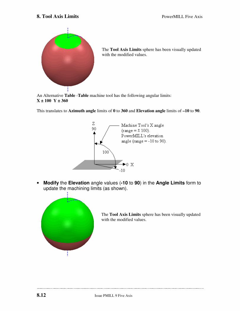
8. Tool Axis Limits PowerMILL Five Axis
8.12 Issue PMILL 9 Five Axis
The Tool Axis Limits sphere has been visually updated
with the modified values.
An Alternative Table -Table machine tool has the following angular limits:
X ± 100 Y ± 360
This translates to Azimuth angle limits of 0 to 360 and Elevation angle limits of –10 to 90.
• Modify the Elevation angle values (-10 to 90) in the Angle Limits form to update the machining limits (as shown).
The Tool Axis Limits sphere has been visually updated
with the modified values.

PowerMILL Five Axis 8. Tool Axis Limits
Issue PMILL 9 Five Axis
8.13
Head – Head Both rotary axes move the head.
With the above Head-Head machine tool the angular limits are specified as:
X ± 60 Z ± 360
The machine tool Z limits are equivalent to the Azimuth angle or the angular limits normal
to the XY plane. In PowerMILL the Z limit of ± 360 translates to Azimuth angle limits of 0
to 360.
The machine tool X limits are equivalent to the Elevation angle above the XY plane. The
angular range of the machine tool is relative to the Z Axis, however PowerMILL measures it
relative to the XY plane. Therefore the angle required for the limit in PowerMILL is the
complementary angle to the one given for the machine tool. The X limit of ± 60 translates to
Elevation angle limits of 30 to 90.
Alternative Head-Head machine tool angular limits:
X –50 to +60
Z ± 360 This translates to Azimuth angle limits of 0 to 360 and Elevation angle limits of 30 to 90. In
this case the machine tool limits across the XZ plane differ. PowerMILL will use the largest
rotational value (+60). This is allowed by rotating the head 180º about Z to provide access to
the maximum range +60 (which otherwise would be -50).
• Modify the Elevation angle values (30 to 90) in the form to update the machining limits as shown on the following page.
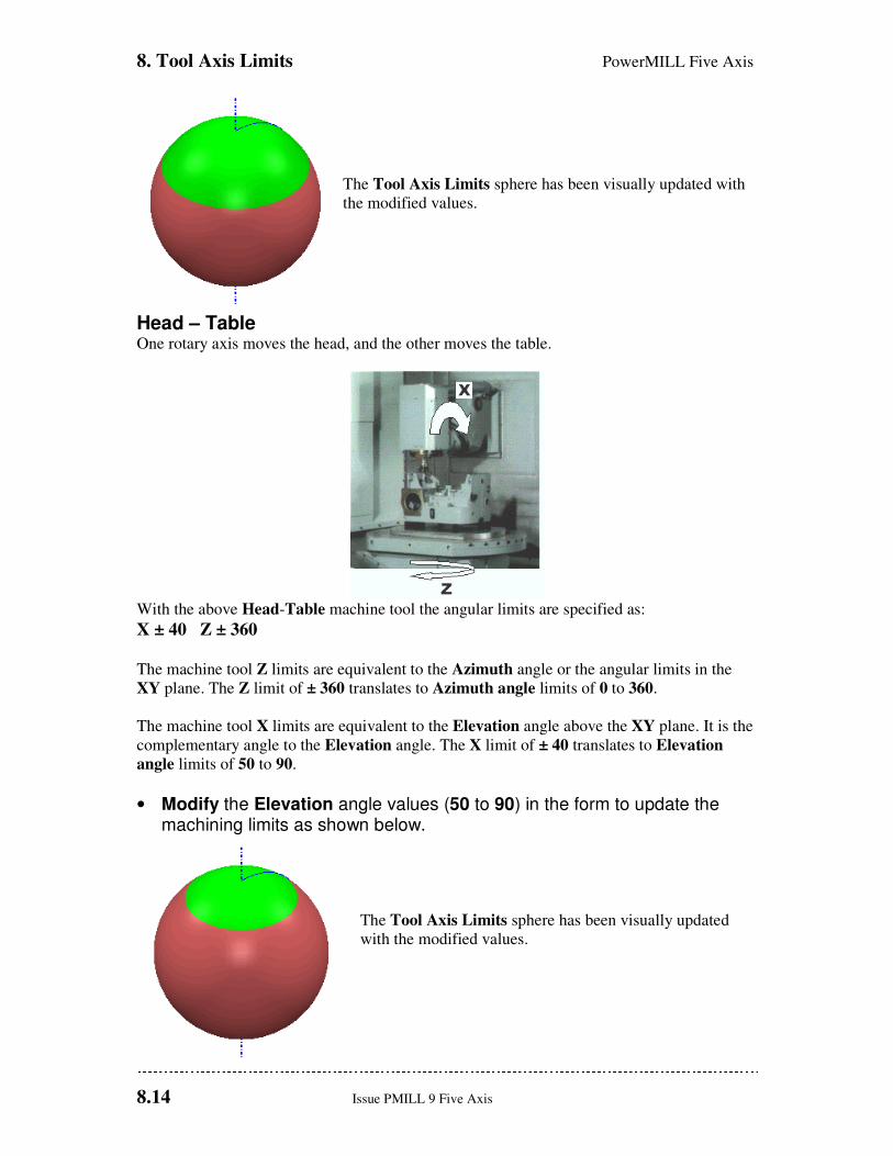
8. Tool Axis Limits PowerMILL Five Axis
8.14 Issue PMILL 9 Five Axis
The Tool Axis Limits sphere has been visually updated with
the modified values.
Head – Table One rotary axis moves the head, and the other moves the table.
With the above Head-Table machine tool the angular limits are specified as:
X ± 40 Z ± 360
The machine tool Z limits are equivalent to the Azimuth angle or the angular limits in the
XY plane. The Z limit of ± 360 translates to Azimuth angle limits of 0 to 360.
The machine tool X limits are equivalent to the Elevation angle above the XY plane. It is the
complementary angle to the Elevation angle. The X limit of ± 40 translates to Elevation
angle limits of 50 to 90.
• Modify the Elevation angle values (50 to 90) in the form to update the machining limits as shown below.
The Tool Axis Limits sphere has been visually updated
with the modified values.
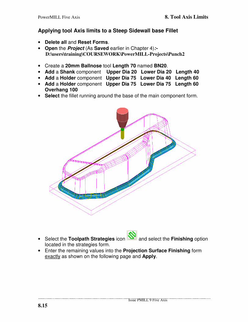
PowerMILL Five Axis 8. Tool Axis Limits
Issue PMILL 9 Five Axis
8.15
Applying tool Axis limits to a Steep Sidewall base Fillet
• Delete all and Reset Forms.
• Open the Project (As Saved earlier in Chapter 4):- D:\users\training\COURSEWORK\PowerMILL-Projects\Punch2
• Create a 20mm Ballnose tool Length 70 named BN20.
• Add a Shank component Upper Dia 20 Lower Dia 20 Length 40
• Add a Holder component Upper Dia 75 Lower Dia 40 Length 60
• Add a Holder component Upper Dia 75 Lower Dia 75 Length 60 Overhang 100
• Select the fillet running around the base of the main component form.
• Select the Toolpath Strategies icon and select the Finishing option located in the strategies form.
• Enter the remaining values into the Projection Surface Finishing form exactly as shown on the following page and Apply.

8. Tool Axis Limits PowerMILL Five Axis
8.16 Issue PMILL 9 Five Axis
During Projection Surface Finishing the tool (bn20) is aligned normal to the Fillet Surface
(if default Lead\Lean 0 is applied). This is creating a Collision situation with both the
sidewall and the base. Tool Axis limits will be applied to prevent this immediate problem as
well as to keep the tool alignment within the machine tool rotary limits.
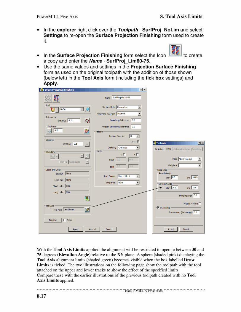
PowerMILL Five Axis 8. Tool Axis Limits
Issue PMILL 9 Five Axis
8.17
• In the explorer right click over the Toolpath - SurfProj_NoLim and select Settings to re-open the Surface Projection Finishing form used to create it.
• In the Surface Projection Finishing form select the Icon to create a copy and enter the Name - SurfProj_Lim60-75.
• Use the same values and settings in the Projection Surface Finishing form as used on the original toolpath with the addition of those shown (below left) in the Tool Axis form (including the tick box settings) and Apply.
With the Tool Axis Limits applied the alignment will be restricted to operate between 30 and
75 degrees (Elevation Angle) relative to the XY plane. A sphere (shaded pink) displaying the
Tool Axis alignment limits (shaded green) becomes visible when the box labelled Draw
Limits is ticked. The two illustrations on the following page show the toolpath with the tool
attached on the upper and lower tracks to show the effect of the specified limits.
Compare these with the earlier illustrations of the previous toolpath created with no Tool
Axis Limits applied.
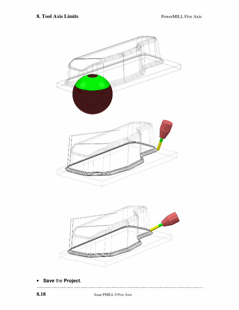
8. Tool Axis Limits PowerMILL Five Axis
8.18 Issue PMILL 9 Five Axis
• Save the Project.
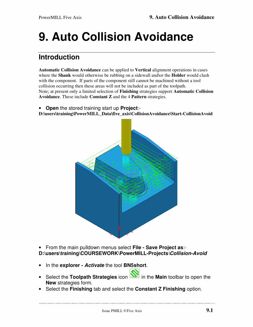
PowerMILL Five Axis 9. Auto Collision Avoidance
Issue PMILL 9 Five Axis 9.1
9. Auto Collision Avoidance
Introduction
Automatic Collision Avoidance can be applied to Vertical alignment operations in cases
where the Shank would otherwise be rubbing on a sidewall and\or the Holder would clash
with the component. If parts of the component still cannot be machined without a tool
collision occurring then these areas will not be included as part of the toolpath.
Note; at present only a limited selection of Finishing strategies support Automatic Collision
Avoidance. These include Constant Z and the 4 Pattern strategies.
• Open the stored training start up Project:- D:\users\training\PowerMILL_Data\five_axis\CollisionAvoidance\Start-CollisionAvoid
• From the main pulldown menus select File - Save Project as:- D:\users\training\COURSEWORK\PowerMILL-Projects\Collision-Avoid
• In the explorer - Activate the tool BN5short.
• Select the Toolpath Strategies icon in the Main toolbar to open the New strategies form.
• Select the Finishing tab and select the Constant Z Finishing option.
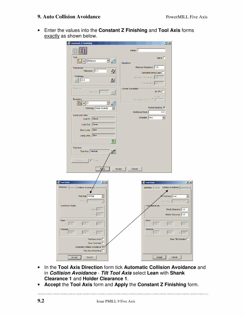
9. Auto Collision Avoidance PowerMILL Five Axis
9.2 Issue PMILL 9 Five Axis
• Enter the values into the Constant Z Finishing and Tool Axis forms exactly as shown below.
• In the Tool Axis Direction form tick Automatic Collision Avoidance and in Collision Avoidance - Tilt Tool Axis select Lean with Shank Clearance 1 and Holder Clearance 1.
• Accept the Tool Axis form and Apply the Constant Z Finishing form.
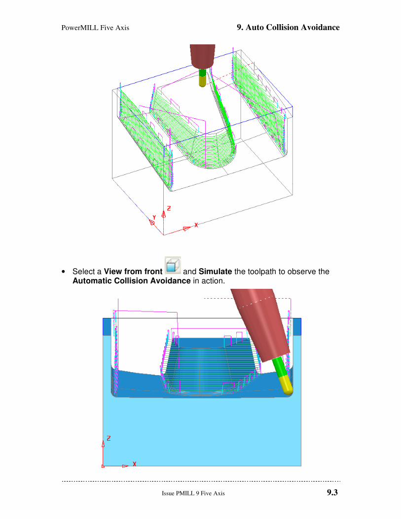
PowerMILL Five Axis 9. Auto Collision Avoidance
Issue PMILL 9 Five Axis 9.3
• Select a View from front and Simulate the toolpath to observe the Automatic Collision Avoidance in action.
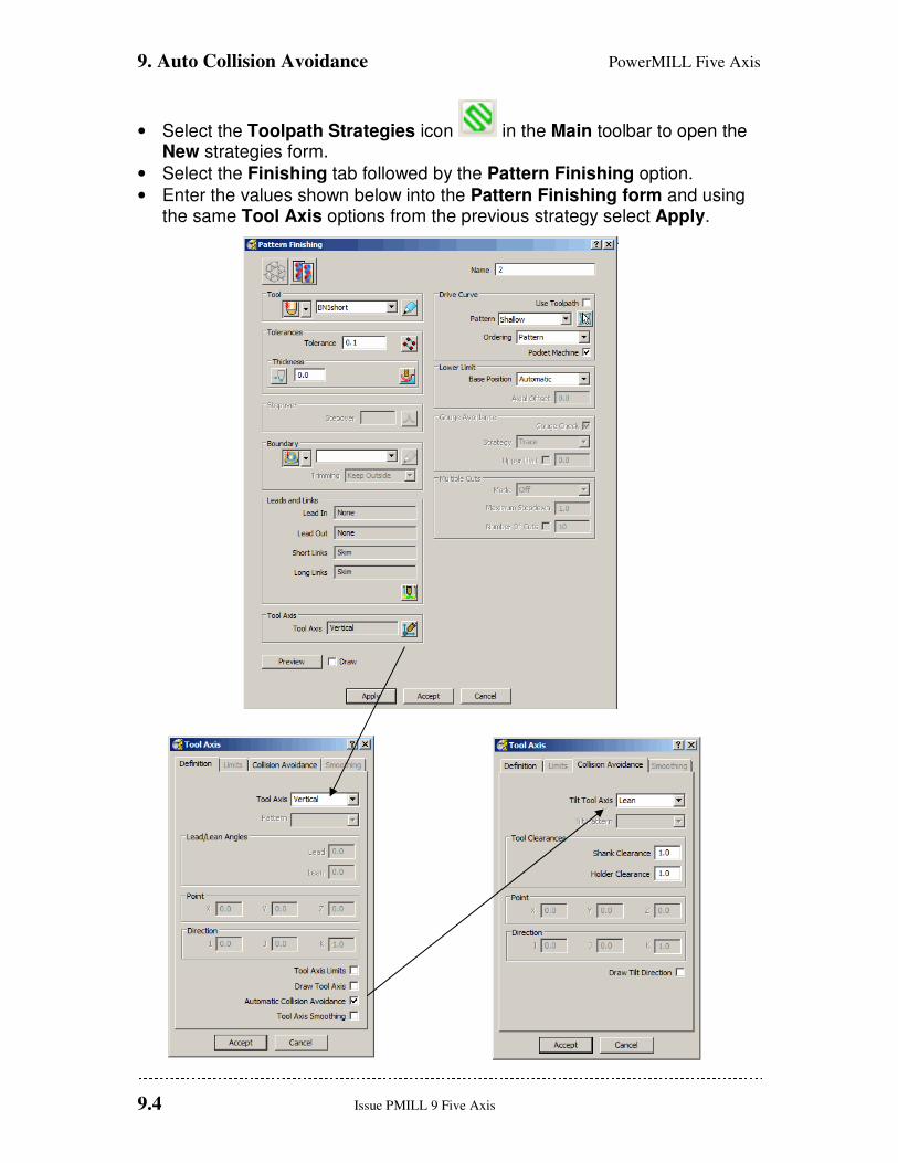
9. Auto Collision Avoidance PowerMILL Five Axis
9.4 Issue PMILL 9 Five Axis
• Select the Toolpath Strategies icon in the Main toolbar to open the New strategies form.
• Select the Finishing tab followed by the Pattern Finishing option.
• Enter the values shown below into the Pattern Finishing form and using the same Tool Axis options from the previous strategy select Apply.
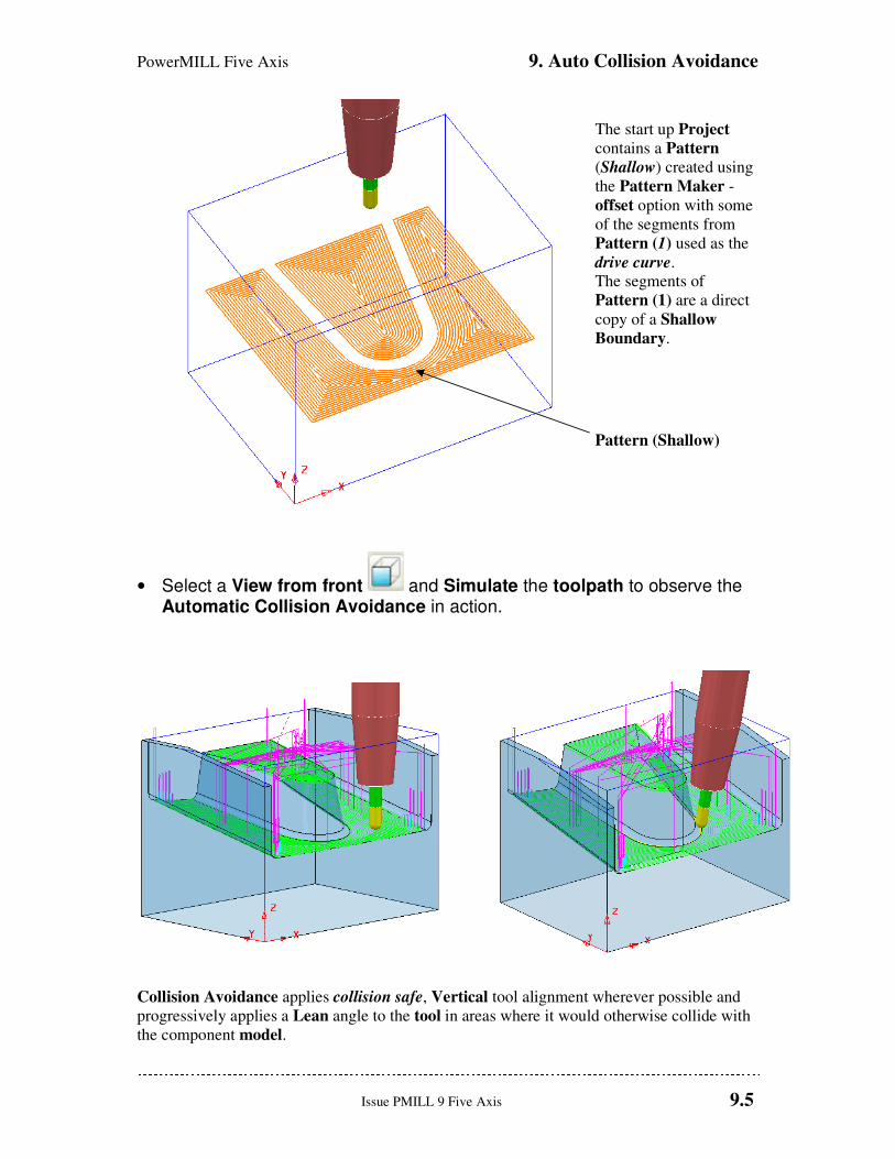
PowerMILL Five Axis 9. Auto Collision Avoidance
Issue PMILL 9 Five Axis 9.5
The start up Project
contains a Pattern
(Shallow) created using
the Pattern Maker -
offset option with some
of the segments from
Pattern (1) used as the
drive curve.
The segments of
Pattern (1) are a direct
copy of a Shallow
Boundary.
Pattern (Shallow)
• Select a View from front and Simulate the toolpath to observe the Automatic Collision Avoidance in action.
Collision Avoidance applies collision safe, Vertical tool alignment wherever possible and
progressively applies a Lean angle to the tool in areas where it would otherwise collide with
the component model.

9. Auto Collision Avoidance PowerMILL Five Axis
9.6 Issue PMILL 9 Five Axis
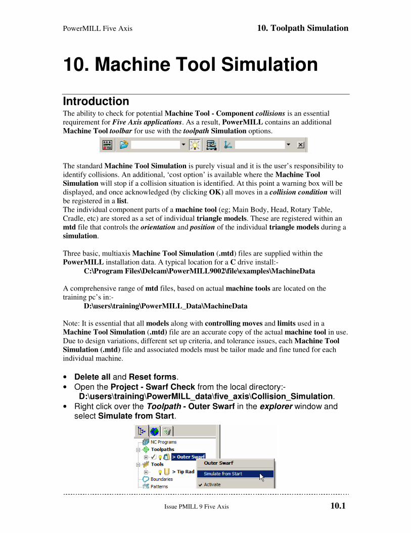
PowerMILL Five Axis 10. Toolpath Simulation
Issue PMILL 9 Five Axis 10.1
10. Machine Tool Simulation
Introduction The ability to check for potential Machine Tool - Component collisions is an essential
requirement for Five Axis applications. As a result, PowerMILL contains an additional
Machine Tool toolbar for use with the toolpath Simulation options.
The standard Machine Tool Simulation is purely visual and it is the user’s responsibility to
identify collisions. An additional, ‘cost option’ is available where the Machine Tool
Simulation will stop if a collision situation is identified. At this point a warning box will be
displayed, and once acknowledged (by clicking OK) all moves in a collision condition will
be registered in a list.
The individual component parts of a machine tool (eg; Main Body, Head, Rotary Table,
Cradle, etc) are stored as a set of individual triangle models. These are registered within an
mtd file that controls the orientation and position of the individual triangle models during a
simulation.
Three basic, multiaxis Machine Tool Simulation (.mtd) files are supplied within the
PowerMILL installation data. A typical location for a C drive install:-
C:\Program Files\Delcam\PowerMILL9002\file\examples\MachineData
A comprehensive range of mtd files, based on actual machine tools are located on the
training pc’s in:-
D:\users\training\PowerMILL_Data\MachineData
Note: It is essential that all models along with controlling moves and limits used in a
Machine Tool Simulation (.mtd) file are an accurate copy of the actual machine tool in use.
Due to design variations, different set up criteria, and tolerance issues, each Machine Tool
Simulation (.mtd) file and associated models must be tailor made and fine tuned for each
individual machine.
• Delete all and Reset forms.
• Open the Project - Swarf Check from the local directory:- D:\users\training\PowerMILL_data\five_axis\Collision_Simulation.
• Right click over the Toolpath - Outer Swarf in the explorer window and select Simulate from Start.
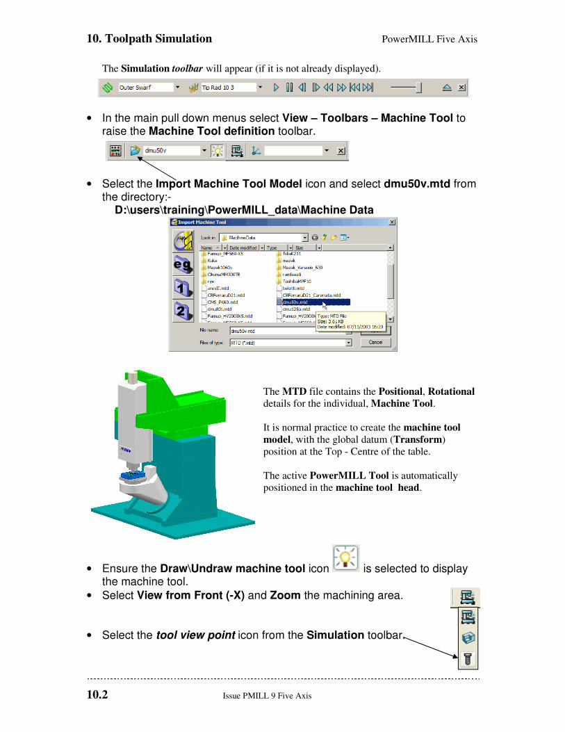
10. Toolpath Simulation PowerMILL Five Axis
10.2 Issue PMILL 9 Five Axis
The Simulation toolbar will appear (if it is not already displayed).
• In the main pull down menus select View – Toolbars – Machine Tool to raise the Machine Tool definition toolbar.
• Select the Import Machine Tool Model icon and select dmu50v.mtd from the directory:-
D:\users\training\PowerMILL_data\Machine Data
The MTD file contains the Positional, Rotational
details for the individual, Machine Tool.
It is normal practice to create the machine tool
model, with the global datum (Transform)
position at the Top - Centre of the table.
The active PowerMILL Tool is automatically
positioned in the machine tool head.
• Ensure the Draw\Undraw machine tool icon is selected to display the machine tool.
• Select View from Front (-X) and Zoom the machining area.
• Select the tool view point icon from the Simulation toolbar.
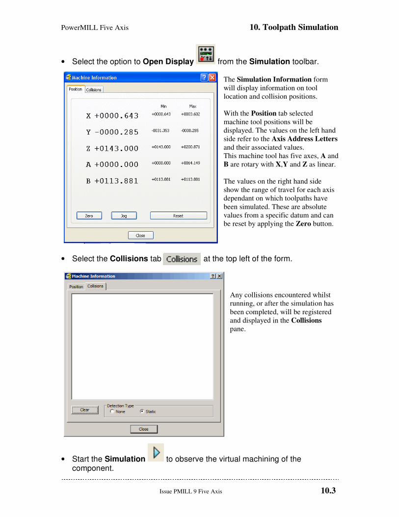
PowerMILL Five Axis 10. Toolpath Simulation
Issue PMILL 9 Five Axis 10.3
• Select the option to Open Display from the Simulation toolbar. The Simulation Information form
will display information on tool
location and collision positions.
With the Position tab selected
machine tool positions will be
displayed. The values on the left hand
side refer to the Axis Address Letters
and their associated values.
This machine tool has five axes, A and
B are rotary with X,Y and Z as linear.
The values on the right hand side
show the range of travel for each axis
dependant on which toolpaths have
been simulated. These are absolute
values from a specific datum and can
be reset by applying the Zero button.
• Select the Collisions tab at the top left of the form.
Any collisions encountered whilst
running, or after the simulation has
been completed, will be registered
and displayed in the Collisions
pane.
• Start the Simulation to observe the virtual machining of the component.
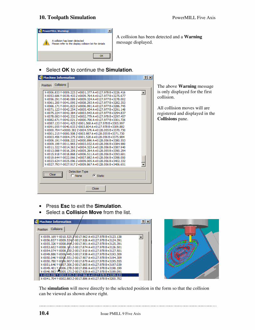
10. Toolpath Simulation PowerMILL Five Axis
10.4 Issue PMILL 9 Five Axis
A collision has been detected and a Warning
message displayed.
• Select OK to continue the Simulation.
The above Warning message
is only displayed for the first
collision.
All collision moves will are
registered and displayed in the
Collisions pane.
• Press Esc to exit the Simulation.
• Select a Collision Move from the list.
The simulation will move directly to the selected position in the form so that the collision
can be viewed as shown above right.

PowerMILL Five Axis 10. Toolpath Simulation
Issue PMILL 9 Five Axis 10.5
With a clear view of the collision, the user can assess how best to make the appropriate
changes to avoid it. In this situation, substituting the cutter with one with increased Tool
Length would be the easiest solution.
• Right click over the tool Tip Rad 10 3 in the explorer window and select Settings.
• Select the holder tab on the tool form and modify the Overhang to 50.
The above PowerMILL Query form
only appears if the tool has been used in
an existing machining strategy.
• In the PowerMILL Query form select Yes to accept the changes to the tool.

10. Toolpath Simulation PowerMILL Five Axis
10.6 Issue PMILL 9 Five Axis
• Close the form and Attach Active Tool to Start from the toolpath in the explorer.
• Select the option to Open Display from the Simulation toolbar.
• Select the Collisions tab on the form.
• Select the Clear tab on the form to clear any existing collisions.
• Start the Simulation .
The Collision Pane remains blank indicating that no collisions have been detected.
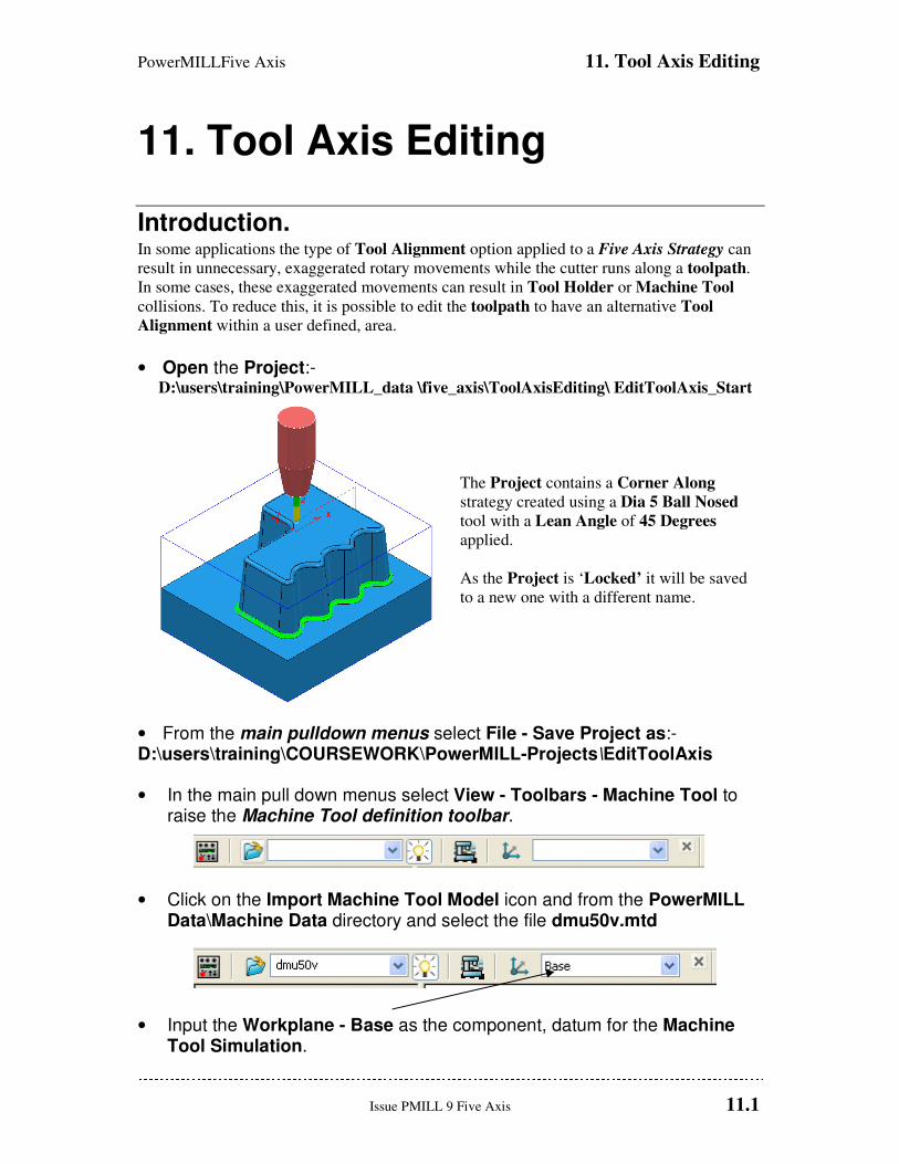
PowerMILLFive Axis 11. Tool Axis Editing
Issue PMILL 9 Five Axis 11.1
11. Tool Axis Editing
Introduction. In some applications the type of Tool Alignment option applied to a Five Axis Strategy can
result in unnecessary, exaggerated rotary movements while the cutter runs along a toolpath.
In some cases, these exaggerated movements can result in Tool Holder or Machine Tool
collisions. To reduce this, it is possible to edit the toolpath to have an alternative Tool
Alignment within a user defined, area.
• Open the Project:- D:\users\training\PowerMILL_data \five_axis\ToolAxisEditing\ EditToolAxis_Start
The Project contains a Corner Along
strategy created using a Dia 5 Ball Nosed
tool with a Lean Angle of 45 Degrees
applied.
As the Project is ‘Locked’ it will be saved
to a new one with a different name.
• From the main pulldown menus select File - Save Project as:- D:\users\training\COURSEWORK\PowerMILL-Projects\EditToolAxis
• In the main pull down menus select View - Toolbars - Machine Tool to raise the Machine Tool definition toolbar.
• Click on the Import Machine Tool Model icon and from the PowerMILL Data\Machine Data directory and select the file dmu50v.mtd
• Input the Workplane - Base as the component, datum for the Machine Tool Simulation.
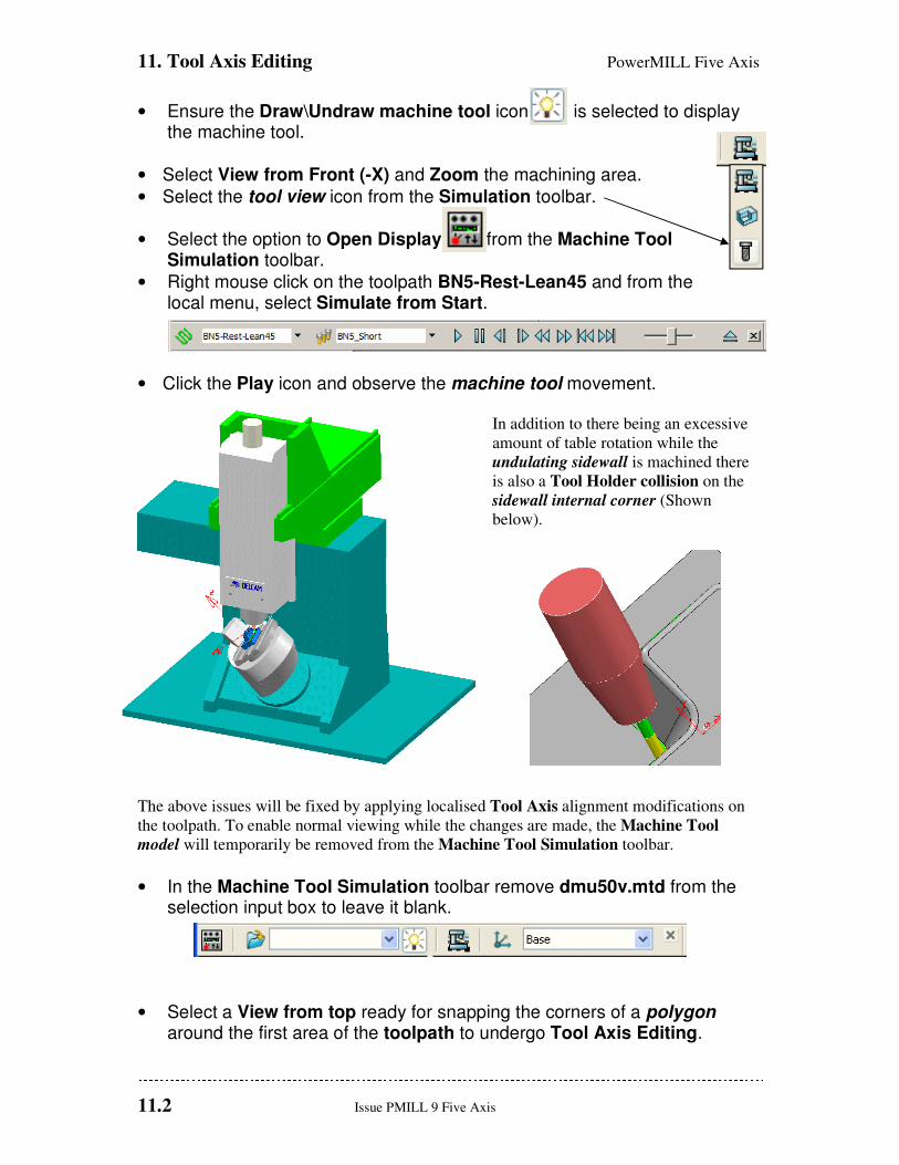
11. Tool Axis Editing PowerMILL Five Axis
11.2 Issue PMILL 9 Five Axis
• Ensure the Draw\Undraw machine tool icon is selected to display the machine tool.
• Select View from Front (-X) and Zoom the machining area.
• Select the tool view icon from the Simulation toolbar.
• Select the option to Open Display from the Machine Tool Simulation toolbar.
• Right mouse click on the toolpath BN5-Rest-Lean45 and from the local menu, select Simulate from Start.
• Click the Play icon and observe the machine tool movement. In addition to there being an excessive
amount of table rotation while the
undulating sidewall is machined there
is also a Tool Holder collision on the
sidewall internal corner (Shown
below).
The above issues will be fixed by applying localised Tool Axis alignment modifications on
the toolpath. To enable normal viewing while the changes are made, the Machine Tool
model will temporarily be removed from the Machine Tool Simulation toolbar.
• In the Machine Tool Simulation toolbar remove dmu50v.mtd from the selection input box to leave it blank.
• Select a View from top ready for snapping the corners of a polygon around the first area of the toolpath to undergo Tool Axis Editing.
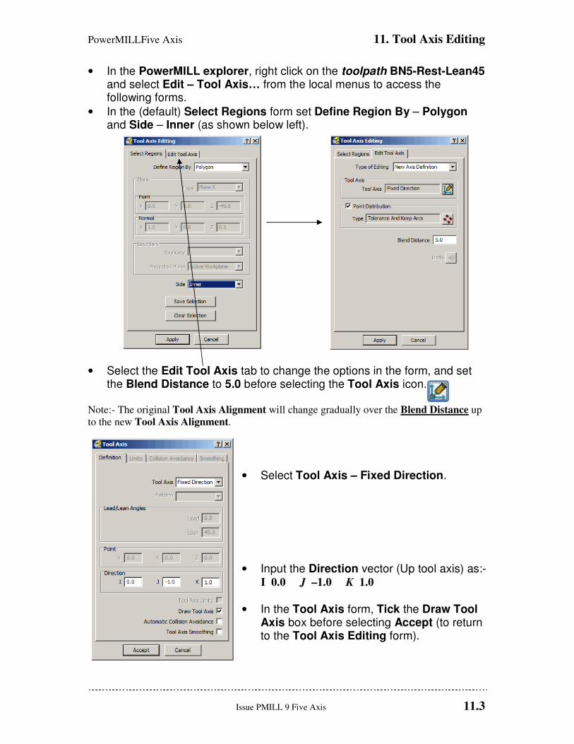
PowerMILLFive Axis 11. Tool Axis Editing
Issue PMILL 9 Five Axis 11.3
• In the PowerMILL explorer, right click on the toolpath BN5-Rest-Lean45 and select Edit – Tool Axis… from the local menus to access the following forms.
• In the (default) Select Regions form set Define Region By – Polygon and Side – Inner (as shown below left).
• Select the Edit Tool Axis tab to change the options in the form, and set the Blend Distance to 5.0 before selecting the Tool Axis icon.
Note:- The original Tool Axis Alignment will change gradually over the Blend Distance up
to the new Tool Axis Alignment.
• Select Tool Axis – Fixed Direction.
• Input the Direction vector (Up tool axis) as:- I 0.0 J –1.0 K 1.0
• In the Tool Axis form, Tick the Draw Tool Axis box before selecting Accept (to return to the Tool Axis Editing form).
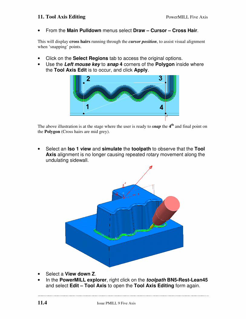
11. Tool Axis Editing PowerMILL Five Axis
11.4 Issue PMILL 9 Five Axis
• From the Main Pulldown menus select Draw – Cursor – Cross Hair. This will display cross hairs running through the cursor position, to assist visual alignment
when ‘snapping’ points.
• Click on the Select Regions tab to access the original options.
• Use the Left mouse key to snap 4 corners of the Polygon inside where the Tool Axis Edit is to occur, and click Apply.
The above illustration is at the stage where the user is ready to snap the 4
th and final point on
the Polygon (Cross hairs are mid grey).
• Select an Iso 1 view and simulate the toolpath to observe that the Tool Axis alignment is no longer causing repeated rotary movement along the undulating sidewall.
• Select a View down Z.
• In the PowerMILL explorer, right click on the toolpath BN5-Rest-Lean45 and select Edit – Tool Axis to open the Tool Axis Editing form again.

PowerMILLFive Axis 11. Tool Axis Editing
Issue PMILL 9 Five Axis 11.5
• In Select Regions select Polygon with Side – Inner, and then click the Edit Tool Axis tab.
• Set Tool Axis to From Point with the coordinate values X-15 Y 25 Z-25, and then tick the box labelled Draw Tool Axis before selecting Accept.
Tool Axis alignment point displayed

11. Tool Axis Editing PowerMILL Five Axis
11.6 Issue PMILL 9 Five Axis
• This time snap 4 corners of the Polygon to form a square, level with the Tool Axis alignment point and click Apply.
Tool Axis alignment point
• Select an Iso 1 view.
• Simulate the toolpath to observe that with the new Tool Axis alignment the Tool Holder is no longer in a collision condition with the sidewall internal corner.
• Perform a Machine Tool Simulation again using the DMU50V with the Floor View selected.
This time the unnecessary, ‘rocking’ movements about
the rotary axis is minimised and the Tool Holder
collision removed.
• From the main pulldown menus, update the Project by selecting:- File - Save
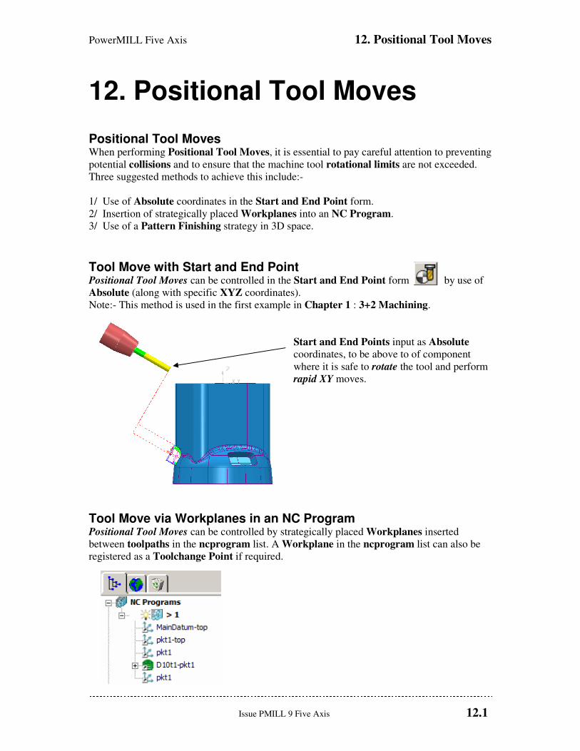
PowerMILL Five Axis 12. Positional Tool Moves
Issue PMILL 9 Five Axis 12.1
12. Positional Tool Moves
Positional Tool Moves When performing Positional Tool Moves, it is essential to pay careful attention to preventing
potential collisions and to ensure that the machine tool rotational limits are not exceeded.
Three suggested methods to achieve this include:-
1/ Use of Absolute coordinates in the Start and End Point form.
2/ Insertion of strategically placed Workplanes into an NC Program.
3/ Use of a Pattern Finishing strategy in 3D space.
Tool Move with Start and End Point Positional Tool Moves can be controlled in the Start and End Point form by use of
Absolute (along with specific XYZ coordinates).
Note:- This method is used in the first example in Chapter 1 : 3+2 Machining.
Start and End Points input as Absolute
coordinates, to be above to of component
where it is safe to rotate the tool and perform
rapid XY moves.
Tool Move via Workplanes in an NC Program Positional Tool Moves can be controlled by strategically placed Workplanes inserted
between toolpaths in the ncprogram list. A Workplane in the ncprogram list can also be
registered as a Toolchange Point if required.
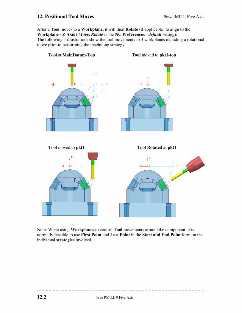
12. Positional Tool Moves PowerMILL Five Axis
12.2 Issue PMILL 9 Five Axis
After a Tool moves to a Workplane, it will then Rotate (if applicable) to align to the
Workplane - Z Axis ( Move, Rotate is the NC Preferences - default setting).
The following 4 illustrations show the tool movements to 3 workplanes including a rotational
move prior to performing the machining strategy.
Tool at MainDatum-Top Tool moved to pkt1-top
Tool moved to pkt1 Tool Rotated at pkt1
Note: When using Workplanes to control Tool movements around the component, it is
normally feasible to use First Point and Last Point in the Start and End Point form on the
individual strategies involved.
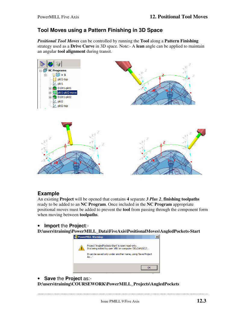
PowerMILL Five Axis 12. Positional Tool Moves
Issue PMILL 9 Five Axis 12.3
Tool Moves using a Pattern Finishing in 3D Space
Positional Tool Moves can be controlled by running the Tool along a Pattern Finishing
strategy used as a Drive Curve in 3D space. Note:- A lean angle can be applied to maintain
an angular tool alignment during transit.
Example An existing Project will be opened that contains 4 separate 3 Plus 2, finishing toolpaths
ready to be added to an NC Program. Once included in the NC Program appropriate
positional moves must be added to prevent the tool from passing through the component form
when moving between toolpaths.
• Import the Project:- D:\users\training\PowerMILL_Data\FiveAxis\PositionalMoves\AngledPockets-Start
• Save the Project as:- D:\users\training\COURSEWORK\PowerMILL_Projects\AngledPockets
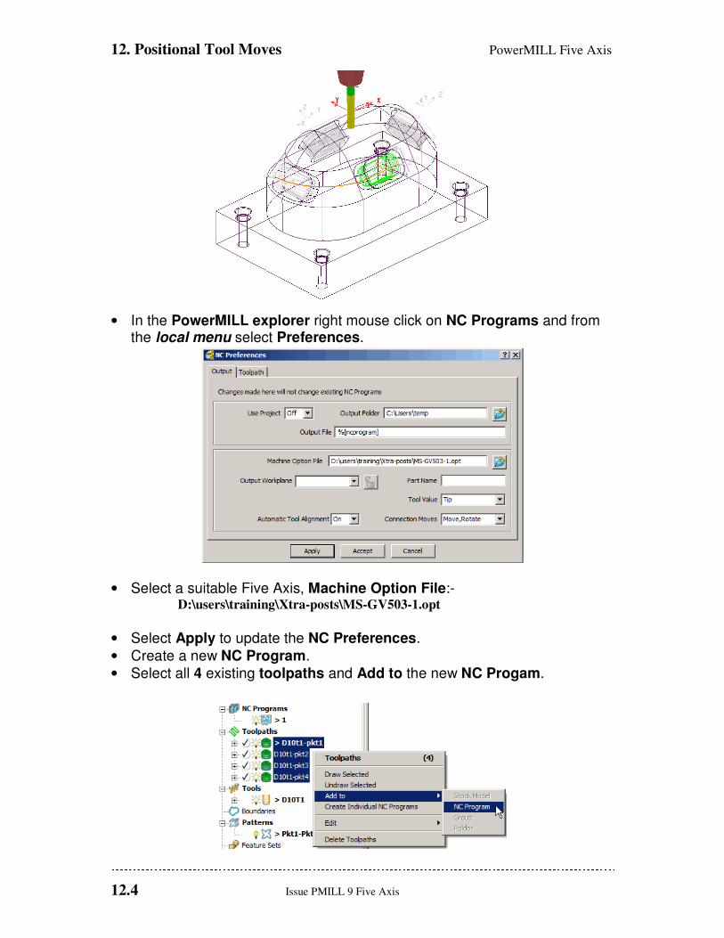
12. Positional Tool Moves PowerMILL Five Axis
12.4 Issue PMILL 9 Five Axis
• In the PowerMILL explorer right mouse click on NC Programs and from the local menu select Preferences.
• Select a suitable Five Axis, Machine Option File:- D:\users\training\Xtra-posts\MS-GV503-1.opt
• Select Apply to update the NC Preferences.
• Create a new NC Program.
• Select all 4 existing toolpaths and Add to the new NC Progam.
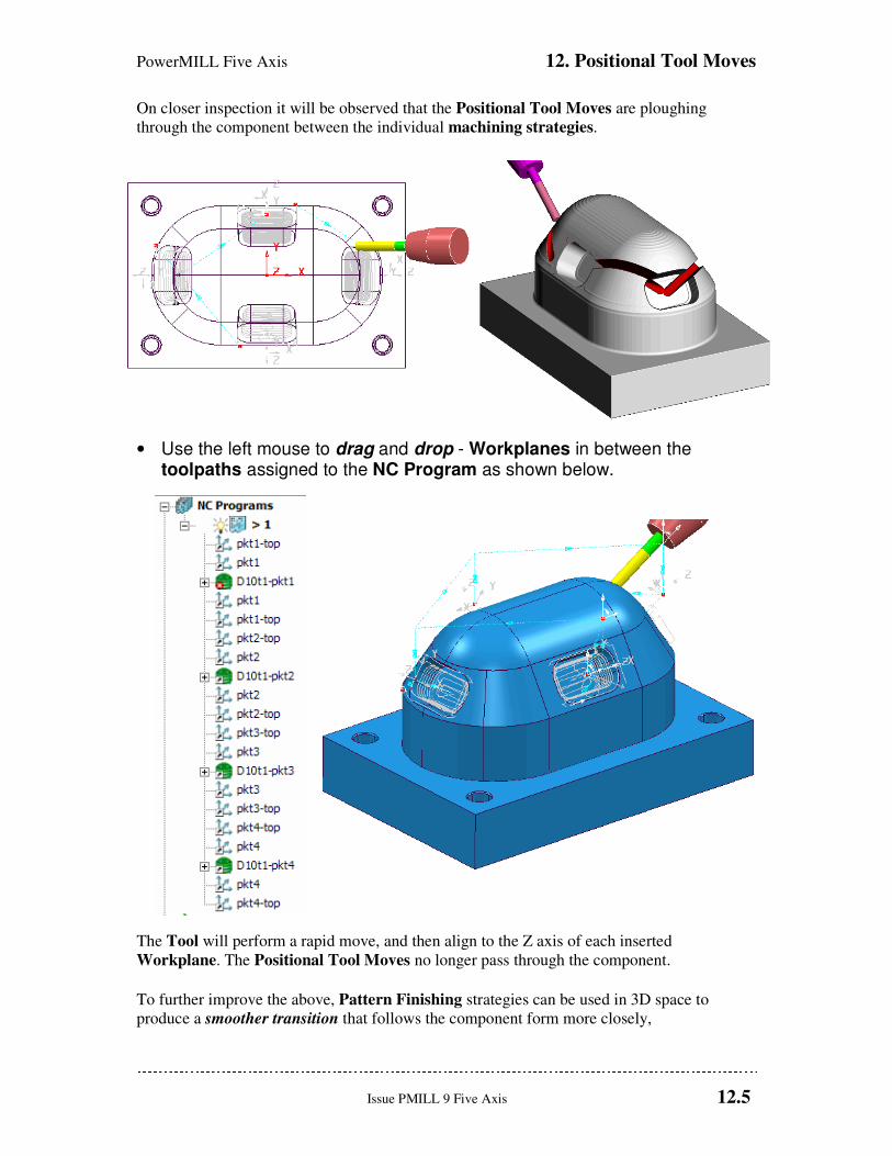
PowerMILL Five Axis 12. Positional Tool Moves
Issue PMILL 9 Five Axis 12.5
On closer inspection it will be observed that the Positional Tool Moves are ploughing
through the component between the individual machining strategies.
• Use the left mouse to drag and drop - Workplanes in between the toolpaths assigned to the NC Program as shown below.
The Tool will perform a rapid move, and then align to the Z axis of each inserted
Workplane. The Positional Tool Moves no longer pass through the component.
To further improve the above, Pattern Finishing strategies can be used in 3D space to
produce a smoother transition that follows the component form more closely,
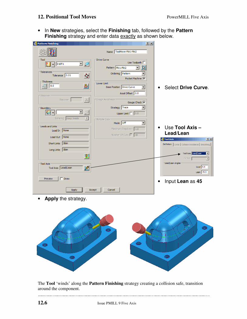
12. Positional Tool Moves PowerMILL Five Axis
12.6 Issue PMILL 9 Five Axis
• In New strategies, select the Finishing tab, followed by the Pattern Finishing strategy and enter data exactly as shown below.
• Select Drive Curve.
• Use Tool Axis – Lead/Lean
• Input Lean as 45
• Apply the strategy.
The Tool ‘winds’ along the Pattern Finishing strategy creating a collision safe, transition
around the component.
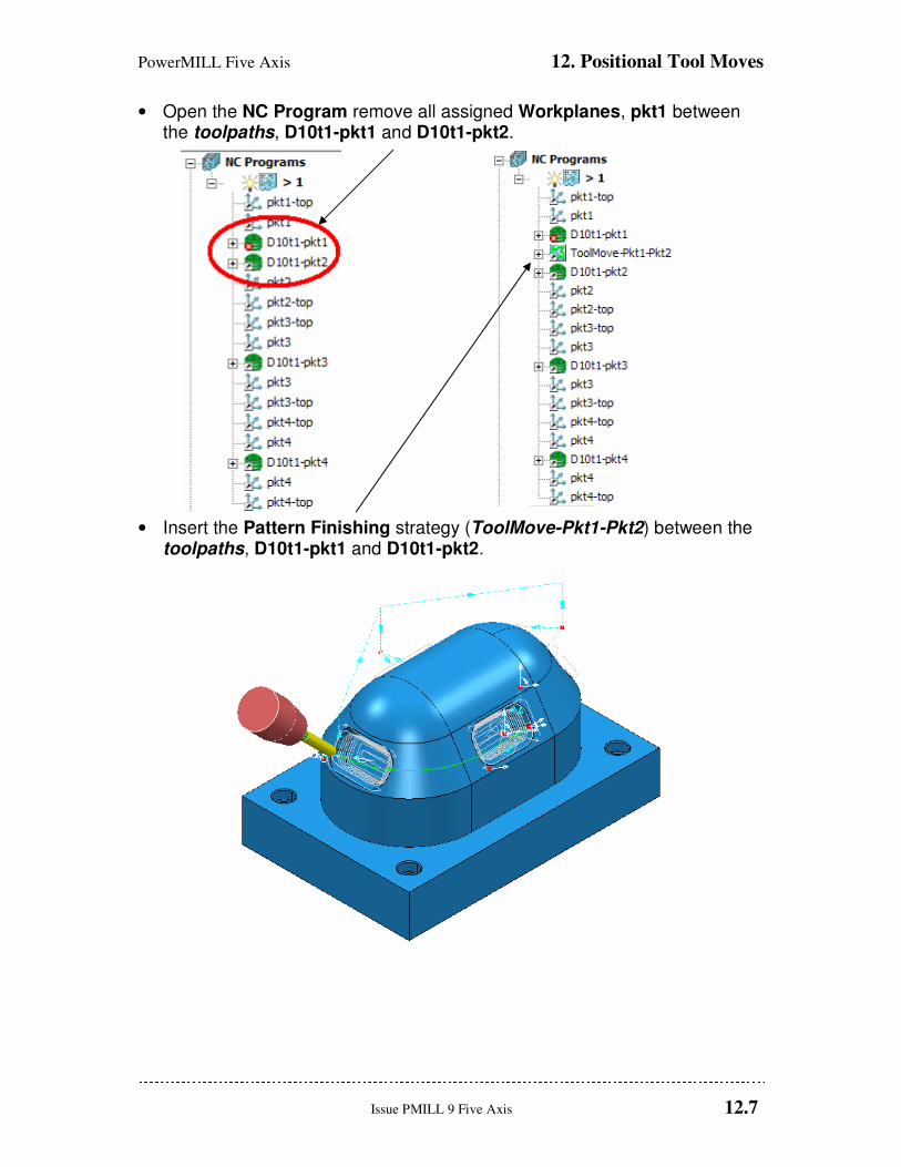
PowerMILL Five Axis 12. Positional Tool Moves
Issue PMILL 9 Five Axis 12.7
• Open the NC Program remove all assigned Workplanes, pkt1 between the toolpaths, D10t1-pkt1 and D10t1-pkt2.
• Insert the Pattern Finishing strategy (ToolMove-Pkt1-Pkt2) between the toolpaths, D10t1-pkt1 and D10t1-pkt2.
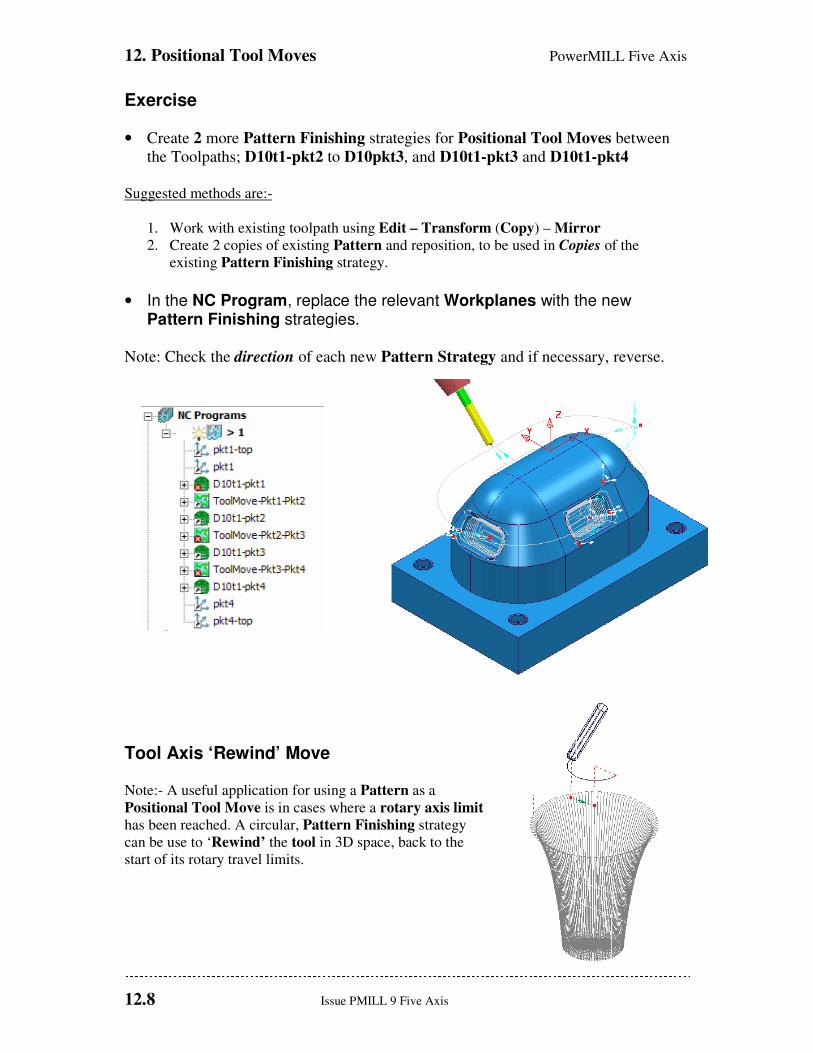
12. Positional Tool Moves PowerMILL Five Axis
12.8 Issue PMILL 9 Five Axis
Exercise
• Create 2 more Pattern Finishing strategies for Positional Tool Moves between
the Toolpaths; D10t1-pkt2 to D10pkt3, and D10t1-pkt3 and D10t1-pkt4
Suggested methods are:-
1. Work with existing toolpath using Edit – Transform (Copy) – Mirror
2. Create 2 copies of existing Pattern and reposition, to be used in Copies of the
existing Pattern Finishing strategy.
• In the NC Program, replace the relevant Workplanes with the new Pattern Finishing strategies.
Note: Check the direction of each new Pattern Strategy and if necessary, reverse.
Tool Axis ‘Rewind’ Move Note:- A useful application for using a Pattern as a
Positional Tool Move is in cases where a rotary axis limit
has been reached. A circular, Pattern Finishing strategy
can be use to ‘Rewind’ the tool in 3D space, back to the
start of its rotary travel limits.

PowerMILL Five Axis 13. Hints and Tips
Issue PMILL 9 Five Axis 13.1
13. Hints and Tips
Useful commands
5-Axis Leads and Links Leads and Links are applied in the same way as for 3-Axis applications and will
automatically take into account the applied 5-Axis - Tool Alignment options .
Useful Preview Commands There are a number of useful commands that may be used to help examine and check the 5-
Axis toolpaths created in PowerMILL. At present these are typed in via the Command
Window.
EDIT TOOLPATH ; AXIAL_OFFSET
This command allows a new offset 5-Axis toolpath to be created from the Active, 5-Axis
toolpath with an offset. All of the points of the new toolpath are calculated from the old
toolpath but offset along the tool axis vector. The actual toolpath name can be inserted
instead of ; if the toolpath is not Active.
EDIT TOOLPATH SHOW_TOOL_AXIS 30 0 This command displays the tool axis vectors from an existing 5-Axis toolpath. The ‘30’ value
in the command line above is the length of the vector. This value can be altered to any value.
EDIT SURFPROJ AUTORANGE OFF
EDIT SURFPROJ RANGEMIN -6
EDIT SURFPROJ RANGEMAX 6 This command sequence limits the Surface Projection distance range to +/- 6mm.
EDIT SURFPROJ AUTORANGE ON This command returns to default no limit to the Surface Projection distance range.

13. Hints and Tips PowerMILL Five Axis
13.2 Issue PMILL 9 Five Axis
Reference Surface Rules
• Keep them simple.
• Don’t follow the form too closely.
• Reference Surface can be Inside/Outside/Both of model, but must be within projection
range.
• Avoid discontinuities.
• Aim for uniform parameterisation.
• Using a small projection range results in a quicker calculation.
• Avoid coincident lats/long as it causes duplicate toolpath segments.
Keep them Simple
Don’t Follow the Model form too closely.

PowerMILL Five Axis 13. Hints and Tips
Issue PMILL 9 Five Axis 13.3
Reference Surface can be Inside/Outside/Both of model, but must be within projection range.
Remember to set the component thickness to ignore if the reference surface is outside or both.
What is the Projection Range?
Setting the projection Range
EDIT SURFPROJ AUTORANGE OFF
EDIT SURFPROJ RANGEMIN -10
EDIT SURFPROJ RANGEMAX 10

13. Hints and Tips PowerMILL Five Axis
13.4 Issue PMILL 9 Five Axis
Avoid discontinuities.
Aim for uniform parameterisation.
Surface internal curves can control the toolpath.