contact probes - feinmetall
TRANSCRIPT

contact probesfor pcb testing
probes for ict and fct interface probes
position testaccessories for test fixtures
Vers
ion
1

2
Contents
Contact Probes for In-Circuit Test and Functional Test (ICT, FCT)
For many years FEINMETALL is a worldwide leading provider of contact probes for ICT and FCT applications. Based on long-term experience and a strong customer focus we have consistently set high standards in developing innovative and practical contacting solutions for contacting PCBs, even with smaller and smaller centers.
These solutions are included in this catalog.
Contact probes for other applications are shown in the corresponding further catalogs.
Probes for ICT / FCTNEW F030 20NEW F031 21NEW F039 22
F040 23F050 28F051 29F075 34F075 HP 33F075 RP 36F100 40F100 HP 42F100 RP 43F111 24F112 25F561 30F562 38F563 53F588 46F701 31F768 26F771 39F772 48F773 54F785 57F786 50F788 27F793 37F796 56F797 52H075 35H100 44Insulating Caps Overview 32
Interface ProbesF100 Special (e.g.: Mint Pin) 63F150 (Teradyne) 67F262 (ATG) 59F502 (L&M) 61F504 (Genrad) 60F538 (L&M) 62
Interface ProbesFP732 (Scorpion) 68Z585 (Agilent, Digitaltest) 65
Probes for Special ApplicationsSwitch Probes (Standard) 70Switch Probes with Ball Head 72Switch Probes with Off-on-off characteristic 73
Description of Positions Sensor System 74
Solutions for Position Test 75High Current Probes 76Coaxial Probes for Kelvin-Mea-surement 78
Coaxial Probes for Radio Frequency Measurement 79
Accessories for Test FixturesBoard Marker 86F419 (NO) 80
NEW Test Connector (HDMI 1.4) 94NEW Test Connector (HDMI 2.0) 95NEW Test Connector (QF) 97NEW Test Connector (RCA) 96NEW Test Connector (RJ-09) 98NEW Test Connector (RJ-11) 99NEW Test Connector (RJ-45) 100NEW Test Connector (RJ-45 f) 101NEW Test Connector (RJ-50) 102NEW Test Connector (USB Micro) 90NEW Test Connector (USB Mini) 91NEW Test Connector (USB 2.0) 92NEW Test Connector (USB 3.0) 93
Interface Blocks (Signal Block) 84Interface Pins (Rigid Contacts) 82Pre-centerings 86
Tools / AccessoriesFDWZ 105FEWZ 105FK50 106Tool Boxes 104
3
NoteThis catalogue contains contact probes for contacting PCBs. The whole contact probe portfolio as well as corresponding step-files for the integration in your CAD-system can be downloaded from our homepage at www.feinmetall.com.
Probes for ICT / FCT 13
Interface Probes 58
Accessories for Test Fixtures 80
Probes for Special Applications 69
Basics 3
Tools / Accessories 103
Tip Styles 6
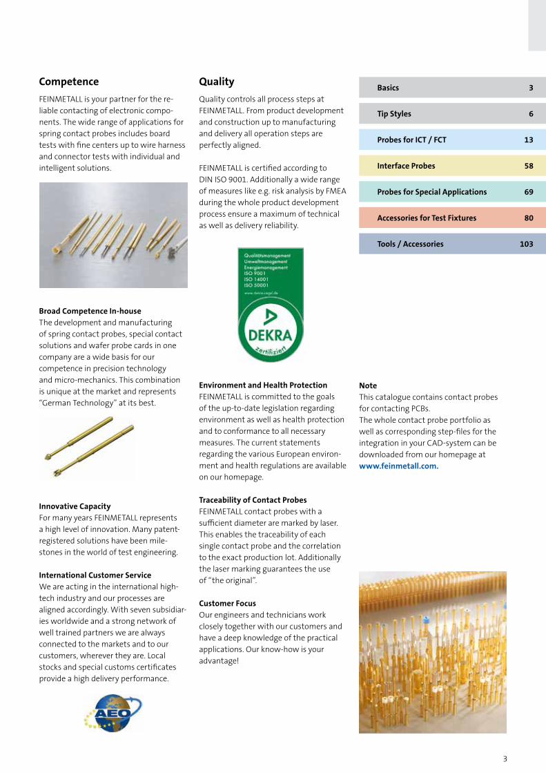
CompetenceFEINMETALL is your partner for the re- liable contacting of electronic compo-nents. The wide range of applications for spring contact probes includes board tests with fine centers up to wire harness and connector tests with individual and intelligent solutions.
Broad Competence In-houseThe development and manufacturing of spring contact probes, special contact solutions and wafer probe cards in one company are a wide basis for our competence in precision technology and micro-mechanics. This combination is unique at the market and represents “German Technology” at its best.
Innovative CapacityFor many years FEINMETALL represents a high level of innovation. Many patent- registered solutions have been mile-stones in the world of test engineering.
International Customer ServiceWe are acting in the international high- tech industry and our processes are aligned accordingly. With seven subsidiar-ies worldwide and a strong network of well trained partners we are always connected to the markets and to our customers, wherever they are. Local stocks and special customs certificates provide a high delivery performance.
Quality Quality controls all process steps at FEINMETALL. From product development and construction up to manufacturing and delivery all operation steps are perfectly aligned.
FEINMETALL is certified according to DIN ISO 9001. Additionally a wide range of measures like e.g. risk analysis by FMEA during the whole product development process ensure a maximum of technical as well as delivery reliability.
Environment and Health ProtectionFEINMETALL is committed to the goals of the up-to-date legislation regarding environment as well as health protection and to conformance to all necessary measures. The current statements regarding the various European environ-ment and health regulations are available on our homepage.
Traceability of Contact ProbesFEINMETALL contact probes with a sufficient diameter are marked by laser. This enables the traceability of each single contact probe and the correlation to the exact production lot. Additionally the laser marking guarantees the use of “the original”.
Customer FocusOur engineers and technicians work closely together with our customers and have a deep knowledge of the practical applications. Our know-how is your advantage!

4
01 02 03 04 05 06Conical 90° Conical 90°
steppedConical 60° Conical 60°
steppedConcave stepped
Serrated stepped
07 09 10 11 12 14Hexagonal 90°
stepped6-point crown 120°
steppedFlexible Needle Spherical Spherical
stepped4-point crown
stepped (self cleaning)
15 16 17 18 21 28Triangular 45°
steppedFlat Flat
steppedConical 30° 4-point crown
(self cleaning)4-point crown
stepped
29 30 32 33 35 364-point crown Triangular
45°Rigid needle
10°Square lance
38°3-point crown
stepped (self cleaning)
6-point crown with middle pin
stepped
37 38 41 43 53 554-point crown
steppedSquare lance
140°6-point crown
stepped (self cleaning)
Square lance90°
Square lance55°
Concave (self cleaning)
62 63 66Triangular
30°8-point crown
stepped (self cleaning)
Serrated stepped
(self cleaning)
Special Versions
(06) IK (17) KIK = Insulating cap K = Synthetic head
BasiCs
Overview of Tip Styles for Board Test
5
BasiCs
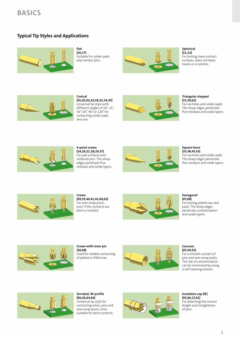
Typical Tip Styles and Applications
Flat(16,17)Suitable for solder pads and contact pins.
Spherical (11,12)For testing clean contact surfaces, does not leave marks or scratches.
Triangular stepped (15,30,62)For via holes and solder pads. The sharp edges penetrate flux residues and oxide layers.
Conical (01,02,03,10,18,32,34,35) Universal tip style with different angles of 10°, 15°, 30°, 60°, 90° or 120° for contacting solder pads and vias.
4-point crown (14,20,21,28,29,37)For pad surfaces and soldered pins. The sharp edges penetrate flux residues and oxide layers.
Hexagonal (07,08)For testing plated vias and pads. The sharp edges penetrate contamination and oxide layers.
Crown (09,35,40,41,42,60,63)For wire wrap posts, even if the contacts are bent or twisted.
Concave (05,50,55)For a smooth contact of pins and wire wrap posts. The risk of contamination can be minimized by using a self cleaning version.
Insulation cap (IK) (05,06,17,41)For detecting the correct length and straightness of pins.
Serrated, W-profile (06,46,64,66)Universal tip style for contacting wires, pins and wire wrap posts, even suitable for bent contacts.
Crown with inner pin (36,68)Used for reliable contacting of plated or filled vias.
Square lance (33,38,43,53)For via holes and solder pads. The sharp edges penetrate flux residues and oxide layers.

6
BasiCs
Design of Spring Contact ProbesSpring contact probes are typically composed of a plunger, a barrel and a spring.
PlungerFEINMETALL manufactures plungers with many different tip styles, suitable for a large variety of applications. Plungers are generally made from beryllium copper (BeCu) or steel. Optimized turning and plating processes are resulting in an outstanding straightness and exactness of the plunger surface, the base for a long lifetime. Aggressive tip styles are made by a special grinding process for ultra sharp edges.
BarrelFEINMETALL barrels are usually made of nickel silver, bronze or brass. Nickel silver barrels are deep-drawn whereas barrels made of bronze are turned or deep-drawn and barrels of brass are turned. All barrels are usually silver or gold plated. A small hole in the bottom permits the barrels to be thoroughly cleaned during manufacturing and ensures continuous wetting in the plating process.
SpringDuring the early years FEINMETALL developed long-life springs for the clock industry and subsequently made use of this knowledge in the manufacturing of spring contact probes. Compression springs are normally made of silver plated music wire or stainless steel, for some special applications also of non-magnetic beryllium copper. Springs made of music wire have a working temperature up to a Maximum of 80°C (176°F) while made of stainless steel or BeCu can be operated up to 200°C (392°F).
Spring ForceThe selection of the spring force mainly depends on the application. On the one hand side the spring force needs to ensure the quality of the electrical contact and the penetration of contami-nations or oxide layers. On the other hand side it should not lead to any damages on
the contacting surface or on the board. It also needs to be taken into consideration that the penetration of the contacted surface highly depends on the chosen tip style. In test fixtures (especially vacuum fixtures) the sum of all spring forces has to be observed in order to close the fixture and the contacts without problems. Due to manufacturing processes and material variances all spring forces have a tolerance of ±20%.
Spring TravelThe spring force increases proportional to the spring travel. This linear function is shown in the force-travel-diagram. During the assembly of the probe the spring is already compressed by a certain travel. The resulting spring force is called preload. The preload makes sure that there is a certain force right from the beginning of the contacting process. Also it makes sure that the plunger is completely pushed back after the contacting. The nominal spring force is the spring force at the recommended working travel. The recommended working travel should not be exceeded significantly, because otherwise the life time of the probe could be considerably reduced.
Electrical SpecificationsIn a contact probe the primary current flow is typically leading through the plunger, the barrel and the receptacle. A secondary current flow is leading through the plunger, the spring and the barrel. The transition points cause certain transfer resistances that are influenced by the following factors:
→ Conductivity of the base material
→ Conductivity of the plating material
→ Condition of the surface of the probe
→ Size of the contact surface
→ Contact forces at the transition points
FEINMETALL is taking measures to guar-antee a constant low contact resistance during the whole lifetime of the probes. The maximum continuous currents and the typical resistances of each specific probe are shown in the data sheets.
Important note for all products with electrically insulated functions like e.g. switch probes, switch recep-tacles, combi receptacles, coaxial probes, insulation caps etc.: For safety reasons according to DIN VDE 0100, part 410, over electrically insulated parts only low-voltages of maximum 25 V (AC) or 60 V (DC) are allowed. These values are effective values including voltage pulses due to over-voltages etc.
Travel [mm]
Preload
Sprin
g fo
rce
[cN
]
Nominal Travel
Maximum Travel
Basic Materials Plating
Barrel Nickel Silver (deep-drawn) SilverBronze (turned or deep-drawn) GoldBrass (drilled)Nickel
Plunger Beryllium-Copper - BeCu (B) Chemical Nickel Steel (S) Gold Synthetic Material (K) FM-Longtime Gold Palladium Alloy (P) Rhodium Brass (M) Progressive Coating
MultiplexSpring Music Wire (max. 80°C) Silver
Stainless Steel (max. 200°C) GoldBeCu (non-magnetic, max. 200°C)
Receptacle Nickel Silver GoldBronzeBrass
BarrelSpringPlunger

7
BasiCs
Different Types of Spring Contact Probes Spring Contact Probes are available for various applications. Below you find a brief overview of the most important types.
ICT/FCT Probes for Test FixturesTest fixtures for in-circuit test (ICT) and functional test (FCT) are mainly equipped with standard probes for the centers 50 mil, 75 mil and 100 mil.
Fine Pitch ProbesContact probes for centers smaller than 1,27 mm / 50 mil are fine pitch probes. In these centers a direct soldering or the use of receptacles is not possible. Therefore most fine pitch probes are designed as double plunger probes to be mounted into sandwich blocks.
Battery ContactsBattery contacts are compact probes, often with a limited travel. They are well suitable as charging contact, but they can also be integrated in end user products whenever low-wear electrical contacts are required.
Interface ProbesInterface probes are used for transmit-ting the signals from the test fixture into the test system. Contact probes for this application are specifically standardized for each test system.
Threaded ProbesContact probes with thread are mainly used in modules for testing connectors and wire harnesses. The advantage is that even under difficult conditions the probes do not move out of the receptacle and a secure seat is guaranteed.
High Current ProbesFor high current applications spring contact probes need to be designed with a very small probe resistance. High current probes are available in different versions and designs.
Switch Probes Special probes with integrated switch element are mainly used for presence tests. Switch probes close or open an electric circuit after a defined travel of the plunger (switch travel). For non-con-ductive contacting, switch probes are available with various insulated tips.
Switch Probes with Ball Head For side contacts with laterally moved test items, FEINMETALL has developed a special switch probe series with a rolling ball as contact element. These probes are less sensitive to lateral forces and have a remarkably higher durability compared to standard probes with only round tip styles.
Pneumatic Switch ProbesFor selective contacting of test points or for positions that are difficult to access, it can be helpful to use pneumatic contact probes, operated by compressed air.
Push Back ProbesDuring the push back test of connectors the tight seat of the connector elements is verified. For this application contact probes with very high spring forces are used.
Kelvin ProbesVery low resistances of components are measured by the 4-wire measurement (Kelvin-method). For this application contacts for the current source and the voltmeter need to be implemented very close to the component. These connec-tions can be realized by special coaxial probes (Kelvin probes), using the outer conductor for the constant current and the inner conductor for measuring the voltage. Therefore measuring errors caused by the connection wires are eliminated.
Radio Frequency ProbesIn many applications, like e.g. testing antenna connectors, radio frequency signals need to be transmitted. To carry these signals, special coaxial contact probes are used. RF probes have an inner conductor for the transmission of the signal and an outer conductor for the electromagnetic shielding.
Fine
pitc
h Pr
obe
Inte
rfac
e Pr
obe
Thre
aded
Pro
be
Hig
h Cu
rren
t Pr
obe
Switc
h Pr
obe
Push
Bac
k Pr
obe
Kelv
in P
robe
Switc
h Pr
obe
with
Bal
l Hea
d
Radi
o Fr
eque
ncy
Pro
be
ICT-
/FCT
Pro
be
Batt
ery
cont
act
Pneu
mat
ic M
icro
Sw
itch
Prob
e

8
The pointing accuracy of a spring contact probe is determined by many factors, for example by manufactur-ing tolerances, by the length of the plungers and by the type of plunger guiding. Further factors that are independent of the contact probe have to be considered, for example the receptacles and the mounting of the test fixture or module.
To optimize the pointing accuracy especially in applications with small centers additional guiding plates in the fixture can be used. There is always a radial tolerance between plunger and barrel of a spring contact probe.
This leads to a certain deflection of the plunger tip. The guide clearance is necessary and if ideally designed, it guarantees a low abrasion and a reduc-tion of lateral forces. The know-how to produce a good functioning and still long living spring contact probe lies in the defi-nition of the optimum tolerances of plunger and barrel.
The most important factor for the pointing accuracy is the radial deflection of the tip compared to the central axis of the probe at the moment of contacting. The specific pointing accuracy in the technical specifications of the probes is approximately corresponding with the maximum radial deflection. The radial deflection can be shown in a diagram.
Pointing Accuracy and Radial Tolerance
The life cycle of spring contact probes is depending on the design of the probes as well as on the operating conditions in the field.
High lateral forces, high current load and contamination may lead to a significantly reduced lifetime of the probes. For us as manufacturer of these probes, it is vital to permanently control and review the quality parameters and to analyze the lifetime performance of our products. In our own laboratory we have various test and measurement setups for quality control and for the determination of technical parameters during research and development. One important subject is the life cycle test, conducted with seven
autonomous stress stages. The test con-ditions provide an internal standard refer-ence that allows competent statements regarding the life cycles of our probes.
Life cycle tests are performed under the following conditions:
→ Ambient temperature: +20°C to +30°C→ Relative humidity: 40 to 60%→ Dust free environment
For the life cycle test up to 10 sample probes are mounted in a stress stage and then pressed with a stroke frequency of 5 to 6 strokes per second. In predetermined steps (e.g. after 2000 strokes) the probes are analyzed in a separate test station and the spring force and the contact resistance of each probe are measured as a function of the spring travel (see picture right on the top). Later the test results are combined in a diagram, showing the whole life cycle of the probe (up to more than a million strokes). The diagrams show typical life cycle test results of spring force and resistance.
Radial Deflection [mm]
BasiCs
Life Cycle Test of Contact Probes
Travel [mm]
Sprin
g Fo
rce
[cN
]
Resi
stan
ce [m
Ohm
]
Contact cycles
Sprin
g Fo
rce
[cN
]
Contact cycles
Resi
stan
ce [m
Ohm
]

9
BasiCs
MaterialsThe optimum performance of a spring contact probe is significantly depending on the selection and combination of ma-terials and platings. Developing, testing and qualifying materials for the various applications is an important aspect of our research and development efforts.
Basic MaterialsFor choosing the optimum basic material for barrel, plunger, spring and receptacle of spring contact probes different aspects need to be considered. Besides the technical applicability also machining and economical facts are relevant for this decision.
Beryllium-Coppercombines outstanding mechanical properties with a high electrical conduc-tivity. It is used for plungers or contact elements in a great variety of products, especially in the field of standard- and high current probes. Also springs can be made of BeCu.
Steelis significantly harder than BeCu and is used for plungers with aggressive tip styles or the requirement of extremely long durability.
Palladium Alloy is used as basic material for plungers. Because of the high hardness it is very robust, an additional plating is not necessary.
Nickel Silveris very resistant to corrosion and is well suitable for machining. Barrels and receptacles made of nickel silver can also be deep drawn economically.
Bronzeis characterized by a combination of good wear resistance, cold formability and high electrical conductivity. It is used for barrels and receptacles.
Brass is an extremely high quality material with a high electrical conductivity, a good wear resistance and the suitability for different ways of machining. It is used for barrels, receptacles and for special shapes.
Plating MaterialsTypically the surfaces of all elements of contact probes are galvanically plated in order to protect the basic material against corrosion. At the assembled contact probe the plating also reduces friction and thereby leads to low abrasion and low contact resistances.
FEINMETALL plating materials are basically galvanic nickel, chemical nickel, gold, hard gold, longtime gold, rhodium, silver or progressive coating. To achieve the maximum performance the ideal selection and combination of coating materials, coating thicknesses, coating alloys as well as various boundary processes have to be made.
Galvanic Nickel has a good chemical durability and a hardness of 300 to 500 HV. It has a good ductility and adheres well to the base material. Nickel also prevents the base material from migrating into the precious metal surface and contaminating it and leads to a high temperature stability and life time.
Chemical Nickelhas a very good chemical durability and is not brittle. It has a hardness of 400 to 600 HV. Chemical nickel is most appro-priate for aggressive tip styles, because it has a good contouring capability and wear resistance.
Rhodiumis extremely resistant to wear and abrasion. Due to its hardness of 800 to 900 HV it is plated on plungers which are used in very rough applications.
Silver is used as a bearing surface and as corrosion protection for barrels and springs. The hardness of the silver layer is 80 to 100 HV only, but it adheres very well to the base material even at small diameters. Silver improves the electrical conductivity.
Gold guarantees the best chemical durability with a hardness of 150 to 200 HV. Gold considerably improves the electrical conductivity. Standard gold is mainly used for plungers made of beryllium- copper or brass.
Hard Goldis the hardest galvanic gold layer with up to 400 HV. Hard gold differs from the other gold types by its slightly lighter color.
FM Longtime Goldis a special gold plating layer system for steel plungers developed by FEINMETALL. The combination of steel and FM-Long-time gold results in a high performance and a long lifetime, even at heavy load applications.
Progressive Coatingis a special coating for contacting lead-free soldering pads and other contaminated or oxidized surfaces. This coating is characterized by a high hardness of 550 to 600 HV and a very low contamination of the tips, which leads to a long lifetime of the probes.
Multiplexis a multi-layer coating system with a very high corrosion resistance. It has been developed for gold plating of steel plungers, that are used in conditions with high humidity.
NickelBarrels in very small diameters can be manufactured by electroforming. In this case nickel is separated and combined with precious metal. This results in pipes with very thin pipe wall of nickel, that can already be gold plated on the inner surface. These barrels are highly precise, however, the thickness of the pipe wall cannot be varied within one part.
10
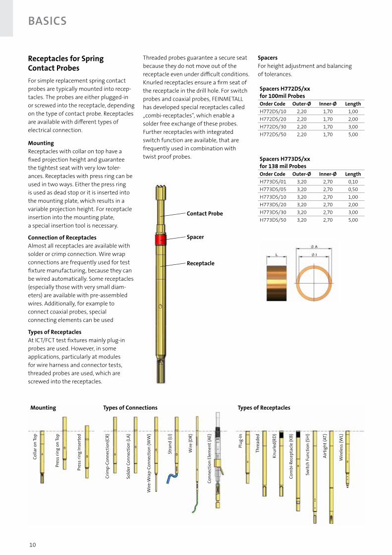
Receptacles for Spring Contact ProbesFor simple replacement spring contact probes are typically mounted into recep-tacles. The probes are either plugged-in or screwed into the receptacle, depending on the type of contact probe. Receptacles are available with different types of electrical connection.
MountingReceptacles with collar on top have a fixed projection height and guarantee the tightest seat with very low toler-ances. Receptacles with press ring can be used in two ways. Either the press ring is used as dead stop or it is inserted into the mounting plate, which results in a variable projection height. For receptacle insertion into the mounting plate, a special insertion tool is necessary.
Connection of ReceptaclesAlmost all receptacles are available with solder or crimp connection. Wire wrap connections are frequently used for test fixture manufacturing, because they can be wired automatically. Some receptacles (especially those with very small diam-eters) are available with pre-assembled wires. Additionally, for example to connect coaxial probes, special connecting elements can be used
Types of ReceptaclesAt ICT/FCT test fixtures mainly plug-in probes are used. However, in some applications, particularly at modules for wire harness and connector tests, threaded probes are used, which are screwed into the receptacles.
Threaded probes guarantee a secure seat because they do not move out of the receptacle even under difficult conditions. Knurled receptacles ensure a firm seat of the receptacle in the drill hole. For switch probes and coaxial probes, FEINMETALL has developed special receptacles called „combi-receptacles“, which enable a solder free exchange of these probes. Further receptacles with integrated switch function are available, that are frequently used in combination with twist proof probes.
Wire
-Wra
p-Co
nnec
tion
(WW
)
Colla
r on
Top
Pres
s rin
g on
Top
Pres
s rin
g In
sert
ed
Crim
p-Co
nnec
tion(
CR)
Sold
er C
onne
ctio
n (L
A)
Stra
nd (L
I)
Wire
(DR)
Conn
ectio
n El
emen
t (AE
)
Plug
-In
Thre
aded
Knur
led(
RD)
Com
bi-R
ecep
tacl
e (K
B)
Switc
h Fu
nctio
n (S
H)
Airt
ight
(AT)
Wire
less
(WL)
Mounting Types of Connections Types of Receptacles
Spacers H772DS/xx for 100mil ProbesOrder Code Outer-Ø Inner-Ø LengthH772DS/10 2,20 1,70 1,00H772DS/20 2,20 1,70 2,00H772DS/30 2,20 1,70 3,00H772DS/50 2,20 1,70 5,00
Spacers H773DS/xx for 138 mil ProbesOrder Code Outer-Ø Inner-Ø LengthH773DS/01 3,20 2,70 0,10H773DS/05 3,20 2,70 0,50H773DS/10 3,20 2,70 1,00H773DS/20 3,20 2,70 2,00H773DS/30 3,20 2,70 3,00H773DS/50 3,20 2,70 5,00
SpacersFor height adjustment and balancing of tolerances.
BasiCs
Contact Probe
Spacer
Receptacle

11
BasiCsOuter-Ø Receptacle [mm]
Drill-Ø [mm]FEINMETALL Receptacles
EP 105 HGW 2372.1
Receptacle with press ring as stop (without knurl)0,66 0,66-0,68 0,66-0,68 H1090,85 0,83-0,84 0,83-0,84 H1110,94 0,94-0,96 0,94-0,96 H6050,95 0,96-0,97 0,97-0,98 H0501,00 0,99-1,00 0,99-1,00 H768, H787, H7301,14 1,12-1,14 1,12-1,14 H7091,20 1,19-1,20 1,19-1,20 H3101,30 1,29-1,30 1,29-1,30 H703, H0751,32 1,31-1,32 1,31-1,32 H7011,50 1,49-1,50 1,49-1,50 -1,56 1,54-1,55 1,54-1,55 H7081,68 1,67-1,68 1,68-1,69 H502, H585, H1001,75 1,73-1,74 1,74-1,75 H3201,80 1,78-1,79 1,78-1,79 H610
2,00 1,99-2,00 1,99-2,00 H722, H732, H712, H752, H756, H757, H772, H875, HVF100
2,10 2,08-2,09 2,08-2,09 H8102,30 2,28-2,29 2,28-2,29 H7022,35 2,33-2,34 2,33-2,34 H3302,36 2,34-2,35 2,34-2,35 H5632,40 2,38-2,39 2,39-2,40 H8912,50 2,48-2,49 2,48-2,49 HVF32,69 2,67-2,68 2,67-2,68 H5642,70 2,68-2,69 2,68-2,69 H3403,00 2,97-2,99 2,97-2,99 HVF4
3,00 2,98-2,99 2,98-2,99 H723, H733, H760, H761, H773, H774, H880, H884, H885, H893
3,40 3,38-3,39 3,39-3,40 H8953,50 3,48-3,49 3,48-3,49 HVF43,56 3,54-3,55 3,54-3,55 H5664,00 3,98-3,99 3,98-3,99 H775, H7354,50 4,48-4,49 4,48-4,49 -4,70 4,68-4,69 4,68-4,69 H820, H8315,00 4,98-4,99 4,98-4,99 -5,50 5,48-5,49 5,48-5,49 -5,60 5,58-5,59 5,58-5,59 -6,50 6,46-6,49 6,46-6,49 H888S18,00 7,98-7,99 7,98-7,99 -9,00 8,96-8,99 8,96-8,99 H888S2
Receptacle with inserted press ring (without knurl)1,05 0,98-1,00 0,99-1,01 H0501,10 1,05-1,08 1,05-1,08 H7871,47 1,36-1,40 1,36-1,40 H703, H0751,80 1,70-1,75 1,70-1,75 -1,81 1,70-1,75 1,70-1,75 H502, H585, H1002,08 2,03-2,05 2,03-2,05 H772, HVF1002,49 2,39-2,44 2,39-2,44 -2,50 2,40-2,45 2,40-2,45 H5632,80 2,72-2,77 2,72-2,77 -2,82 2,75-2,78 2,75-2,78 H5643,66 3,58-3,63 3,58-3,63 H566
Receptacle with collar as stop (with knurl)(1,32) 1,35 R 1,32-1,34 1,32-1,34 H175(1,67) 1,70 R 1,67-1,68 1,67-1,68 H731(2,00) 2,05 R 2,00-2,02 2,00-2,02 H732, H875(2,75) 2,95 R 2,92-2,94 2,92-2,94 -(3,00) 3,05 R 3,00-3,02 3,00-3,02 H733, H737, H881, H885(3,45) 3,55 R 3,47-3,52 3,47-3,52 H755(3,50) 3,56 R 3,50-3,52 3,50-3,52 H887(4,70) 4,74 R 4,70-4,72 4,70-4,72 H831(6,50) 6,80 R 6,55-6,75 6,55-6,75 H888RD(8,70) 8,90 R 8,75-8,85 8,75-8,85 H888RDS1
Contact probe (with knurl)(1,65) 1,72 R 1,66 1,66 F752(2,50) 2,55 R 2,50-2,52 2,50-2,52 V03
(2,565) 2,70 R 2,66 2,66 F754Interface pins
1,43-1,53 1,44-1,49 1,44-1,49 I-Z11,45-1,50 1,45-1,48 1,45-1,48 I-G
(1,33) 1,50 R 1,40-1,47 1,40-1,47 I-G1(1,98) 2,03 R 1,98-2,00 1,98-2,00 I-D, I-C(2,45) 2,60 R 2,55-2,57 I-P1
Contact probe directly inserted in drill hole (without knurl)… drill-Ø = outer-Ø of the barrel all plug-in contact probes
Drilling Recommendations Mounting the receptacle into the mount-ing plate demands special precision. Various parameters like rotating speed, feed, helical groove length, material and plate thickness are influencing the drilling results. The drilling recommendations in the technical specifications of the probes are guideline values only as a basis for your own drilling trials. Therefore it is very important to make drilling tests in order to ensure that the receptacles have a proper seat in the mounting plate.
Press ring as stop
Contact probe without receptacle
Interface pin
Contact probe with knurl
With receptacle with collar as stop
With inserted Press ring
Material- characteristics FR4 CEM1
Density (g/cm³) 1,70 - 1,90 1,54Humidity- absorption (%) 0,15 0,15
Thermal conduc-tivity (W/m K) 0,30 0,20
Operation temperature permanent (°C)
155 130
12
BasiCs
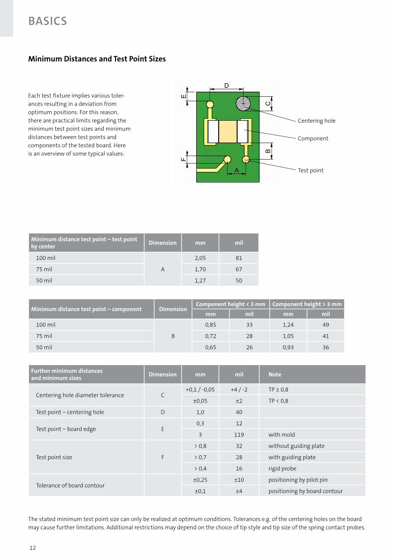
Each test fixture implies various toler-ances resulting in a deviation from optimum positions. For this reason, there are practical limits regarding the minimum test point sizes and minimum distances between test points and components of the tested board. Here is an overview of some typical values:
Minimum Distances and Test Point Sizes
Minimum distance test point – component DimensionComponent height < 3 mm Component height > 3 mm
mm mil mm mil
100 mil
B
0,85 33 1,24 49
75 mil 0,72 28 1,05 41
50 mil 0,65 26 0,93 36
Minimum distance test point – test pointby center Dimension mm mil
100 mil
A
2,05 81
75 mil 1,70 67
50 mil 1,27 50
Further minimum distances and minimum sizes Dimension mm mil Note
Centering hole diameter tolerance C+0,1 / -0,05 +4 / -2 TP ≥ 0,8
±0,05 ±2 TP < 0,8
Test point – centering hole D 1,0 40
Test point – board edge E0,3 12
3 119 with mold
Test point size F
> 0,8 32 without guiding plate
> 0,7 28 with guiding plate
> 0,4 16 rigid probe
Tolerance of board contour±0,25 ±10 positioning by pilot pin
±0,1 ±4 positioning by board contour
The stated minimum test point size can only be realized at optimum conditions. Tolerances e.g. of the centering holes on the board may cause further limitations. Additional restrictions may depend on the choice of tip style and tip size of the spring contact probes.
E
D
CB
A
F
Centering hole
Component
Test point

13Edition 06/2017. All rights reserved. Not all combinations are available. Further versions can be found at www.feinmetall.com
For the in-circuit and functional test of PCBs standard probes in the centers 50 mil, 75 mil and 100 mil are most commonly used. In these applications long lifetime, reliable contacts and great variety of tip styles and spring forces are essential.
Additionally, for many applications special solutions are required like e.g. for contacting lead-free soldered pads as well as contaminated, oxidized or OSP-coated boards.
Probes for In-Circuit- and Functional TestF030 20 F031 21F039 22F040 23F111 24F112 25 F768 26 F788 27F050 28F051 29F561 30F701 31Insulation caps 32F075 33F793 37F562 38F771 39F100 40F588 46F772 48F786 50F797 52 F563 53F773 54F796 56F785 57
14
ICT/FCT Probes
Edition 06/2017. All rights reserved. Not all combinations are available. Further versions can be found at www.feinmetall.com
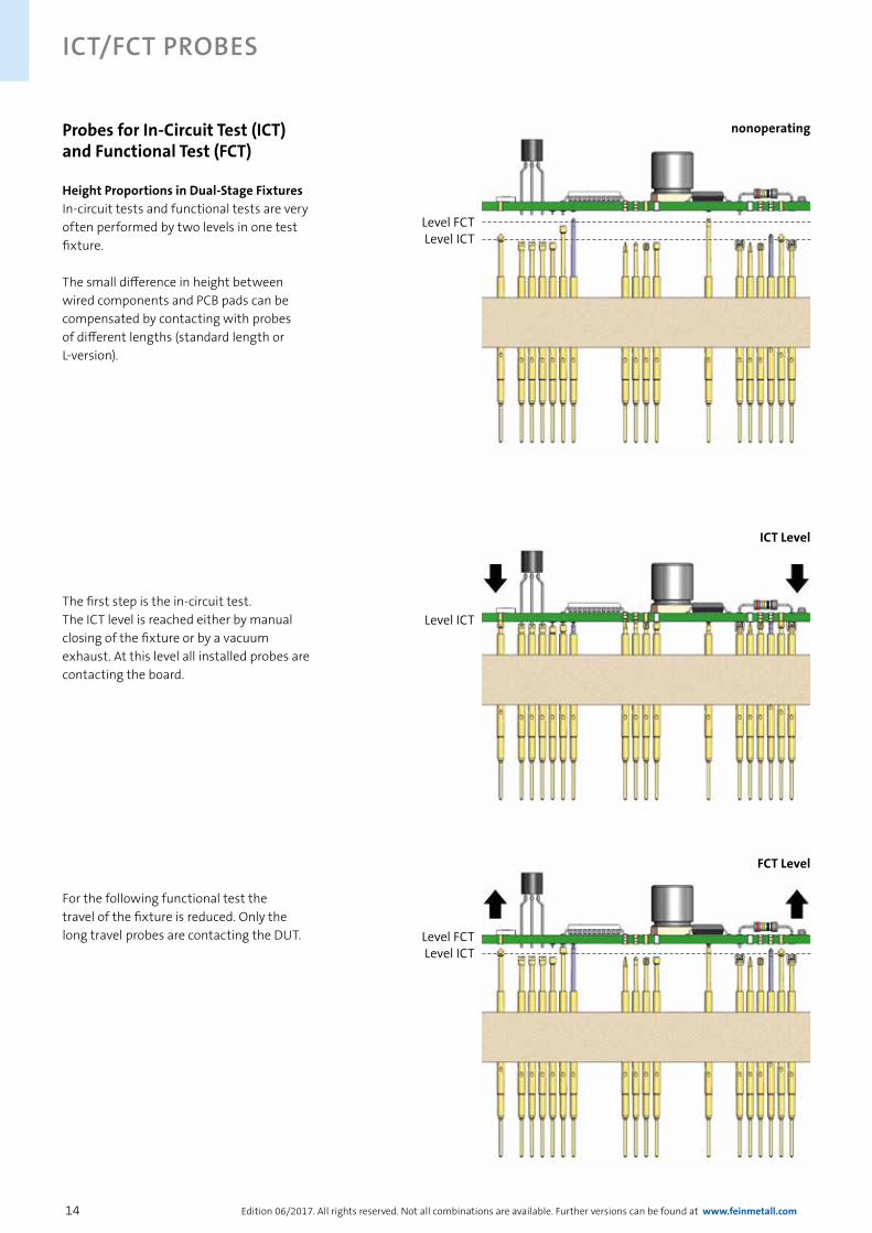
The first step is the in-circuit test. The ICT level is reached either by manual closing of the fixture or by a vacuum exhaust. At this level all installed probes are contacting the board.
Probes for In-Circuit Test (ICT) and Functional Test (FCT)
Height Proportions in Dual-Stage FixturesIn-circuit tests and functional tests are very often performed by two levels in one test fixture.
The small difference in height between wired components and PCB pads can be compensated by contacting with probes of different lengths (standard length or L-version).
For the following functional test the travel of the fixture is reduced. Only the long travel probes are contacting the DUT.
ICT Level
FCT Level
Level ICTLevel FCT
nonoperating
Level ICTLevel FCT
Level ICT
15
ICT/FCT Probes
Edition 06/2017. All rights reserved. Not all combinations are available. Further versions can be found at www.feinmetall.com
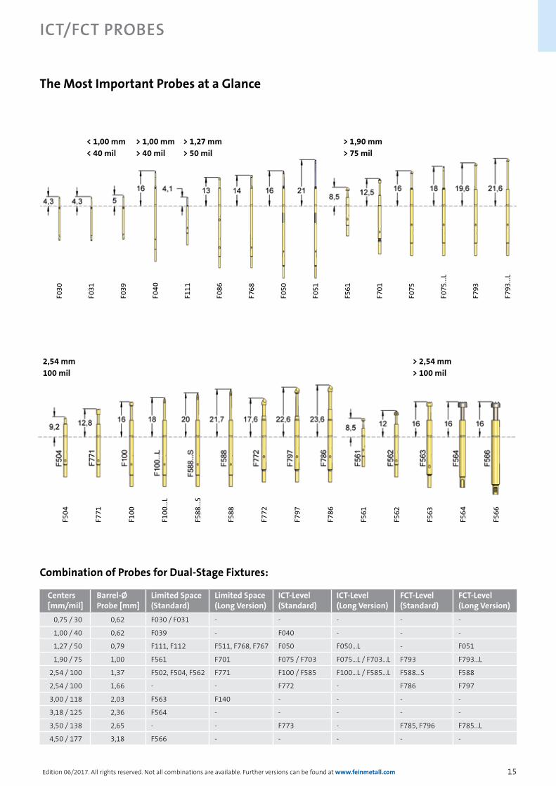
The Most Important Probes at a Glance
Centers [mm/mil]
Barrel-Ø Probe [mm]
Limited Space (Standard)
Limited Space (Long Version)
ICT-Level (Standard)
ICT-Level (Long Version)
FCT-Level (Standard)
FCT-Level (Long Version)
0,75 / 30 0,62 F030 / F031 - - - - -
1,00 / 40 0,62 F039 - F040 - - -
1,27 / 50 0,79 F111, F112 F511, F768, F767 F050 F050...L - F051
1,90 / 75 1,00 F561 F701 F075 / F703 F075...L / F703...L F793 F793...L
2,54 / 100 1,37 F502, F504, F562 F771 F100 / F585 F100...L / F585...L F588...S F588
2,54 / 100 1,66 - - F772 - F786 F797
3,00 / 118 2,03 F563 F140 - - - -
3,18 / 125 2,36 F564 - - - - -
3,50 / 138 2,65 - - F773 - F785, F796 F785...L
4,50 / 177 3,18 F566 - - - - -
Combination of Probes for Dual-Stage Fixtures:
< 1,00 mm < 40 mil
> 1,90 mm > 75 mil
> 1,27 mm > 50 mil
> 1,00 mm > 40 mil
F793
...L
F793
F075
...L
F075
F701
F561
F051
F050
F768
F086
F111
F040
F039
F031
F030
2,54 mm 100 mil
> 2,54 mm > 100 mil
F566
F564
F563
F562
F561
F786
F797
F772
F588
F588
...S
F100
...L
F100
F771
F504

16
ICT/FCT Probes
Edition 06/2017. All rights reserved. Not all combinations are available. Further versions can be found at www.feinmetall.com
for component pins
for viasfor solder pads
Applications with Special Challenges
Lead free soldering and contaminated surfacesThe changeover from leaded to lead free soldering has caused some unexpected problems. The most important disadvantages are the 10 to 30 K increased melting temperature and a higher aggressiveness against metallic materials. The necessary soldering parameters for lead free soldering often lead to a decomposition of tools or test equipment that is directly contacting the soldering metal. Additionally, lead free solders and surfaces have less universal applications and cause technical problems like embrittlement or whisker formation. These conditions also cause strong challenges regarding the contacting, similar to the problems caused by contaminations or oxidation.
FEINMETALL offers a great variety of specially developed spring contact probes for exactly these challenges. These solutions are already proofed and established in many customers’ applications.
Progressive coating
Gold coating
17
ICT/FCT Probes
Edition 06/2017. All rights reserved. Not all combinations are available. Further versions can be found at www.feinmetall.com
Applications with Special Challenges
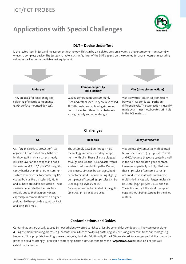
OSP
OSP (organic surface protection) is an organic dilution based on substituted imidazoles. It is a transparent, nearly invisible layer on the copper and has a thickness of 0,2 to 0,6 μm. OSP is signifi-cantly harder than tin or other common surface refinements. For contacting OSP coated boards the tip styles 32, 33, 38 and 43 have proved to be suitable. These variants penetrate the hard surface reliably due to their aggressiveness, especially in combination with a higher preload. So they provide a good contact and long life times.
Bent pins
The assembly based on through hole technology is characterized by compo-nents with pins. These pins are plugged through holes in the PCB and afterwards soldered onto conductor paths. During this process pins can be damaged, bent or contaminated. For contacting slightly bent pins, self-centering tip styles can be used (e.g. tip style 05 or 55). For contacting contaminated pins e.g. tip styles 06, 14, 55 or 63 are used.
Empty or filled vias
Vias are usually contacted with pointed tips or sharp lances (e.g. tip styles 15, 33 and 62), because these are centering well in the hole and create a good contact. However, at partially or fully filled vias these tip styles often come to rest on not conductive materials. In this case multi-sided lances with larger angles can be useful (e.g. tip styles 38, 43 and 53). These tips contact the via at the upper edge without being stopped by the filled material.
Challenges
DUT – Device Under Testis the tested item in test and measurement technology. This can be an isolated area on a wafer, a single component, an assembly or even a complete device. The tested characteristics or features of the DUT depend on the required test parameters or measuring values as well as on the available test equipment.
Solder pads
They are used for positioning and soldering of electric components (SMD, surface mounted devices).
Vias (through connections)
Vias are vertical electrical connections between PCB conductor paths on different levels. The connection is usually made by an inner metal-coated drill hole in the PCB material.
Component pins by THT assembly
Leaded components are commonly used and established. They are also called THT (through hole technology) compo-nents. It can be differentiated between axially, radially and other designs.
Contaminations and Oxides
Contaminations are usually caused by not sufficiently wetted vanishes or just by general dust or deposits. They can occur either during the manufacturing process, e.g. because of residues of soldering paste or glues, or during later conditions and storage, e.g. because of inappropriate handling, grease spots, oils, dust etc. Additionally, if the PCBs are stored for a longer period, the conductor paths can oxidize strongly. For reliable contacting in these difficult conditions the Progressive Series is an excellent and well established solution.
18
ICT/FCT Probes
Edition 06/2017. All rights reserved. Not all combinations are available. Further versions can be found at www.feinmetall.com
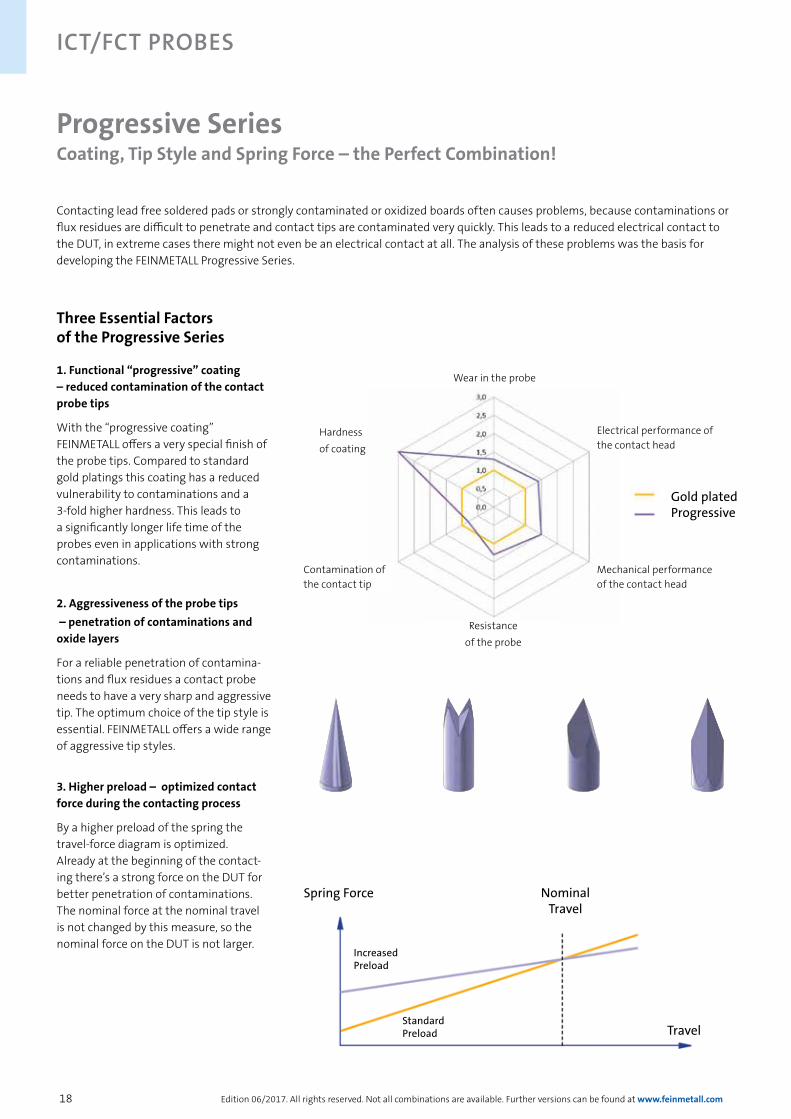
Contacting lead free soldered pads or strongly contaminated or oxidized boards often causes problems, because contaminations or flux residues are difficult to penetrate and contact tips are contaminated very quickly. This leads to a reduced electrical contact to the DUT, in extreme cases there might not even be an electrical contact at all. The analysis of these problems was the basis for developing the FEINMETALL Progressive Series.
Progressive SeriesCoating, Tip Style and Spring Force – the Perfect Combination!
Three Essential Factors of the Progressive Series
1. Functional “progressive” coating – reduced contamination of the contact probe tips
With the “progressive coating” FEINMETALL offers a very special finish of the probe tips. Compared to standard gold platings this coating has a reduced vulnerability to contaminations and a 3-fold higher hardness. This leads to a significantly longer life time of the probes even in applications with strong contaminations.
2. Aggressiveness of the probe tips – penetration of contaminations and oxide layers
For a reliable penetration of contamina-tions and flux residues a contact probe needs to have a very sharp and aggressive tip. The optimum choice of the tip style is essential. FEINMETALL offers a wide range of aggressive tip styles.
3. Higher preload – optimized contact force during the contacting process
By a higher preload of the spring the travel-force diagram is optimized. Already at the beginning of the contact-ing there’s a strong force on the DUT for better penetration of contaminations. The nominal force at the nominal travel is not changed by this measure, so the nominal force on the DUT is not larger.
Spring Force
Travel
Nominal Travel
Standard Preload
Increased Preload
Mechanical performance of the contact head
Electrical performance of the contact head
Contamination of the contact tip
Hardness of coating
Wear in the probe
Gold platedProgressive
Resistance of the probe
19
ICT/FCT Probes
Edition 06/2017. All rights reserved. Not all combinations are available. Further versions can be found at www.feinmetall.com
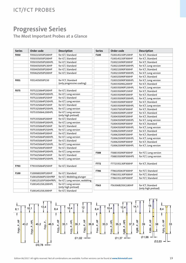
Progressive SeriesThe Most Important Probes at a Glance
Series Order code DescriptionF050 F05021S050P200HP for ICT, Standard
F05033S050P200HP for ICT, StandardF05033S050P200HPL for ICT, StandardF05043S050P130HP for ICT, StandardF05043S050P200HP for ICT, StandardF05062S050P200HP for ICT, Standard
F051 F05143S050P150 for FCT, Standard (only progressive coating)
F075 F07521S064P200HP for ICT, StandardF07521S064P200HPL for ICT, Long versionF07521S064P250HP for ICT, StandardF07521S064P250HPL for ICT, Long versionF07532S064P250HP for ICT, StandardF07532S064P250HPL for ICT, Long versionF07533S064L200HPL for ICT, Long version
(only high preload)F07533S064P200HP for ICT, StandardF07533S064P200HPL for ICT, Long versionF07533S064P250HP for ICT, StandardF07533S064P250HPL for ICT, Long versionF07543S064P200HP for ICT, StandardF07543S064P200HPL for ICT, Long versionF07543S064P250HP for ICT, StandardF07543S064P250HPL for ICT, Long versionF07562S064P200HP for ICT, StandardF07562S064P200HPL for ICT, Long versionF07562S064P250HP for ICT, StandardF07562S064P250HPL for ICT, Long version
F793 F79333S064P250HP for ICT, Standard
F100 F10006B200P100HP for ICT, StandardF10010S060P150HPRP for ICT, Wobbling plungerF10012S105P300HPRPL for ICT, Long version, wobblingF10014S150L200HPL for ICT, Long version
(only high preload)F10014S150L300HP for ICT, Standard
Series Order code DescriptionF100 F10014S150P130HP for ICT, Standard
F10014S150P300HP for ICT, StandardF10021S090P200HP for ICT, StandardF10021S090P200HPL for ICT, Long versionF10021S090P300HP for ICT, StandardF10021S090P300HPL for ICT, Long versionF10032S090P300HP for ICT, StandardF10032S090P300HPL for ICT, Long versionF10033S090L200HP for ICT, StandardF10033S090P130HPL for ICT, Long versionF10033S090P150HP for ICT, StandardF10033S090P200HP for ICT, StandardF10033S090P200HPL for ICT, Long versionF10033S090P300HP for ICT, StandardF10033S090P300HPL for ICT, Long versionF10037S050P300HP for ICT, StandardF10043S090P130HP for ICT, StandardF10043S090P200HP for ICT, StandardF10043S090P200HPL for ICT, Long versionF10043S090P300HP for ICT, StandardF10043S090P300HPL for ICT, Long versionF10062S090P150HP for ICT, StandardF10062S090P200HP for ICT, StandardF10062S090P200HPL for ICT, Long versionF10062S090P300HP for ICT, StandardF10062S090P300HPL for ICT, Long version
F588 F58833S090P300HP for FCT, Long versionF58833S090P300HPS for FCT, Long version
F772 F77233S130P300HP for ICT, Standard
F786 F78610S063P300HP for FCT, StandardF78633S130P300HP for FCT, StandardF78633S130P500HP for FCT, Standard
F563 F56306B250G180HP for ICT, Standard (only high preload)

20
ICT/FCT Probes
Edition 06/2017. All rights reserved. Not all combinations are available. Further versions can be found at www.feinmetall.com
F030Probe 30 milStandard
Series Tip-Ø
Spring Force (cN)
F030 18 E 038 M 080 AE
Tip Style
Material Plating
Version
Material: E = Stainless steelTip-Ø: 038 = 0,38 mm (e.g.)
Plating: M = Multiplex coatingReceptacle: Order Code according drawing
Spring Force (cN ±20%)Version Preload NominalStandard 35 80
Travel (mm)Version Nominal MaximumStandard 2,0 3,5Pointing Accuracy ±0,05 mm
Materials and PlatingPlunger see tip styleBarrel Bronze, gold platedSpring Music wire, silver plated
AccessoriesConnecting element H031-0001
Drill size (mm)Barrel-Ø 0,61 - 0,63
Tip Style Number Material Plating ∅ in mm Version
18 E M 0,38 -
18 E M 0,38 AE
Centers (mm/mil) 0,76 / 30
Current 1,5 A
R typ 150 mOhm
Temperature -20°C...+80°C
NEW
The AE variant is the combination of F030 and H031-0001.

21
ICT/FCT Probes
Edition 06/2017. All rights reserved. Not all combinations are available. Further versions can be found at www.feinmetall.com
F031Probe 31 milStandard
Series Tip-Ø
Spring Force (cN)
F031 18 S 040 M 080 AE
Tip Style
Material Plating
Version
Material: S = Steel; E = Stainless steelTip-Ø: 040= 0,40 mm (e.g.)
Plating: M = Multiplex coatigReceptacle: Order Code according drawing
Spring Force (cN ±20%)Version Preload NominalStandard 35 80
Travel (mm)Version Nominal MaximumStandard 2,0 3,5Pointing Accuracy ±0,05 mm
Materials and PlatingPlunger see tip styleBarrel Bronze, gold platedSpring Music wire, silver platedConnecting element BeCu, gold plated
AccessoriesConnecting element H031AE
Drill size (mm)Barrel-Ø 0,63 - 0,65
Tip Style Number Material Plating ∅ in mm Version
18 E M 0,40 -
18 E M 0,40 AE
Centers (mm/mil) 0,80 / 31
Current 1,5 A
R typ 150 mOhm
Temperature -20°C...+80°C
NEW
The AE variant is the combination of F031 and H031-0001.
22
ICT/FCT Probes
Edition 06/2017. All rights reserved. Not all combinations are available. Further versions can be found at www.feinmetall.com
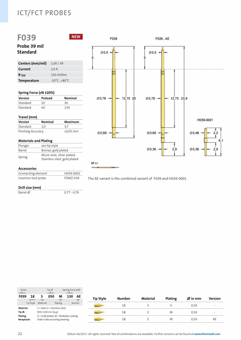
F039Probe 39 milStandard
Spring Force (cN ±20%)Version Preload NominalStandard 10 30Standard 60 130
Travel (mm)Version Nominal MaximumStandard 2,0 3,7Pointing Accuracy ±0,05 mm
Materials and PlatingPlunger see tip styleBarrel Bronze, gold plated
Spring Music wire, silver plated Stainless steel, gold plated
AccessoriesConnecting element H039-0001Insertion tool probe FDWZ-039
Drill size (mm)Barrel-Ø 0,77 - 0,79
Centers (mm/mil) 1,00 / 39
Current 2,0 A
R typ 150 mOhm
Temperature -20°C...+80°C
Series Tip-Ø
Spring Force (cN)
F039 18 S 050 M 130 AE
Tip Style
Material Plating
Version
Material: S = Steel; E = Stainless steelTip-Ø: 050= 0,50 mm (e.g.)
Plating: G = Gold plated; M = Multiplex coatingReceptacle: Order Code according drawing
Tip Style Number Material Plating ∅ in mm Version
18 S G 0,50 -
18 E M 0,50 -
18 E M 0,50 AE
NEW
The AE variant is the combined variant of F039 and H039-0001.

23
ICT/FCT Probes
Edition 06/2017. All rights reserved. Not all combinations are available. Further versions can be found at www.feinmetall.com
F040Probe 40 milStandard
Series Tip-Ø
Spring Force (cN)
F040 18 S 038 L 080
Tip Style
Material Plating
Version
Material: S = SteelTip-Ø: 038 = 0,38 mm (e.g.)
Plating: L = Longtime Gold platedReceptacle: Order Code according drawing
Spring Force (cN ±20%)Version Preload NominalStandard 40 80
Travel (mm)Version Nominal MaximumStandard 4,3 6,4Pointing Accuracy ±0,05 mm
Materials and PlatingPlunger see tip styleBarrel Bronze, gold platedSpring Music wire, gold platedReceptacle Nickel silver, gold plated
AccessoriesInsertion tool receptacle FEWZ-040E0Insertion tool probe FDWZ-050
Drill size (mm)Press ring as stop 0,80 - 0,81Press ring inserted 0,82 - 0,83
Projection Height (mm)H040... with F040 8,1 - 16,0
Tip Style Number Material Plating ∅ in mm Version
18 S L 0,38 -
29 S L 0,38 -
33 S L 0,38 -
43 S L 0,38 -
Centers (mm/mil) 1,00 / 40
Current 2,0 A
R typ 20 mOhm
Temperature -20°C...+80°C
WireAWG301000 mm
24
ICT/FCT Probes
Edition 06/2017. All rights reserved. Not all combinations are available. Further versions can be found at www.feinmetall.com
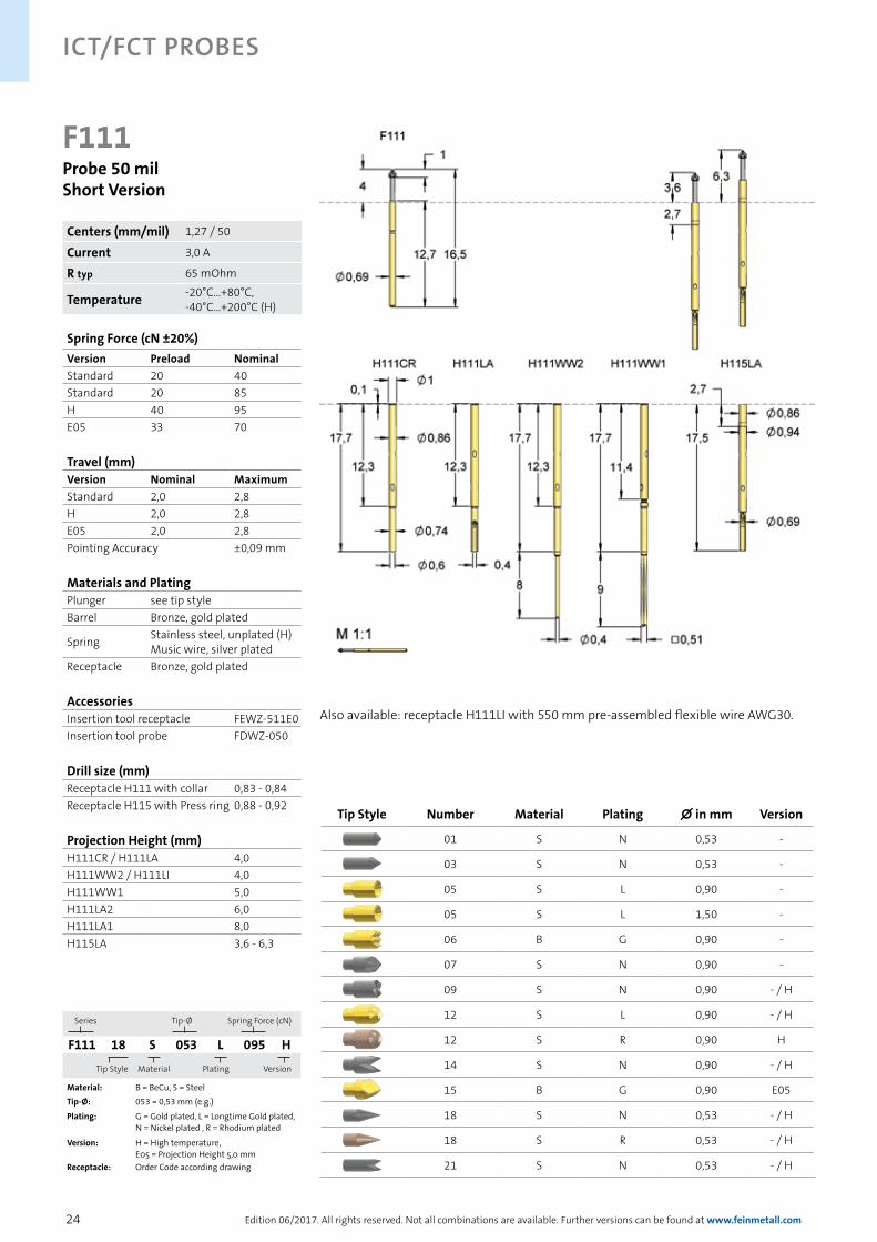
F111Probe 50 milShort Version
Series Tip-Ø
Spring Force (cN)
F111 18 S 053 L 095 H
Tip Style
Material Plating
Version
Material: B = BeCu, S = SteelTip-Ø: 053 = 0,53 mm (e.g.)
Plating: G = Gold plated, L = Longtime Gold plated, N = Nickel plated , R = Rhodium plated
Version: H = High temperature, E05 = Projection Height 5,0 mm
Receptacle: Order Code according drawing
Also available: receptacle H111LI with 550 mm pre-assembled flexible wire AWG30.
Spring Force (cN ±20%)Version Preload NominalStandard 20 40Standard 20 85H 40 95E05 33 70
Travel (mm)Version Nominal MaximumStandard 2,0 2,8H 2,0 2,8E05 2,0 2,8Pointing Accuracy ±0,09 mm
Materials and PlatingPlunger see tip styleBarrel Bronze, gold plated
Spring Stainless steel, unplated (H)Music wire, silver plated
Receptacle Bronze, gold plated
AccessoriesInsertion tool receptacle FEWZ-511E0Insertion tool probe FDWZ-050
Drill size (mm)Receptacle H111 with collar 0,83 - 0,84Receptacle H115 with Press ring 0,88 - 0,92
Projection Height (mm)H111CR / H111LA 4,0H111WW2 / H111LI 4,0H111WW1 5,0H111LA2 6,0H111LA1 8,0H115LA 3,6 - 6,3
Tip Style Number Material Plating ∅ in mm Version
01 S N 0,53 -
03 S N 0,53 -
05 S L 0,90 -
05 S L 1,50 -
06 B G 0,90 -
07 S N 0,90 -
09 S N 0,90 - / H
12 S L 0,90 - / H
12 S R 0,90 H
14 S N 0,90 - / H
15 B G 0,90 E05
18 S N 0,53 - / H
18 S R 0,53 - / H
21 S N 0,53 - / H
Centers (mm/mil) 1,27 / 50
Current 3,0 A
R typ 65 mOhm
Temperature -20°C...+80°C, -40°C...+200°C (H)
25
ICT/FCT Probes
Edition 06/2017. All rights reserved. Not all combinations are available. Further versions can be found at www.feinmetall.com
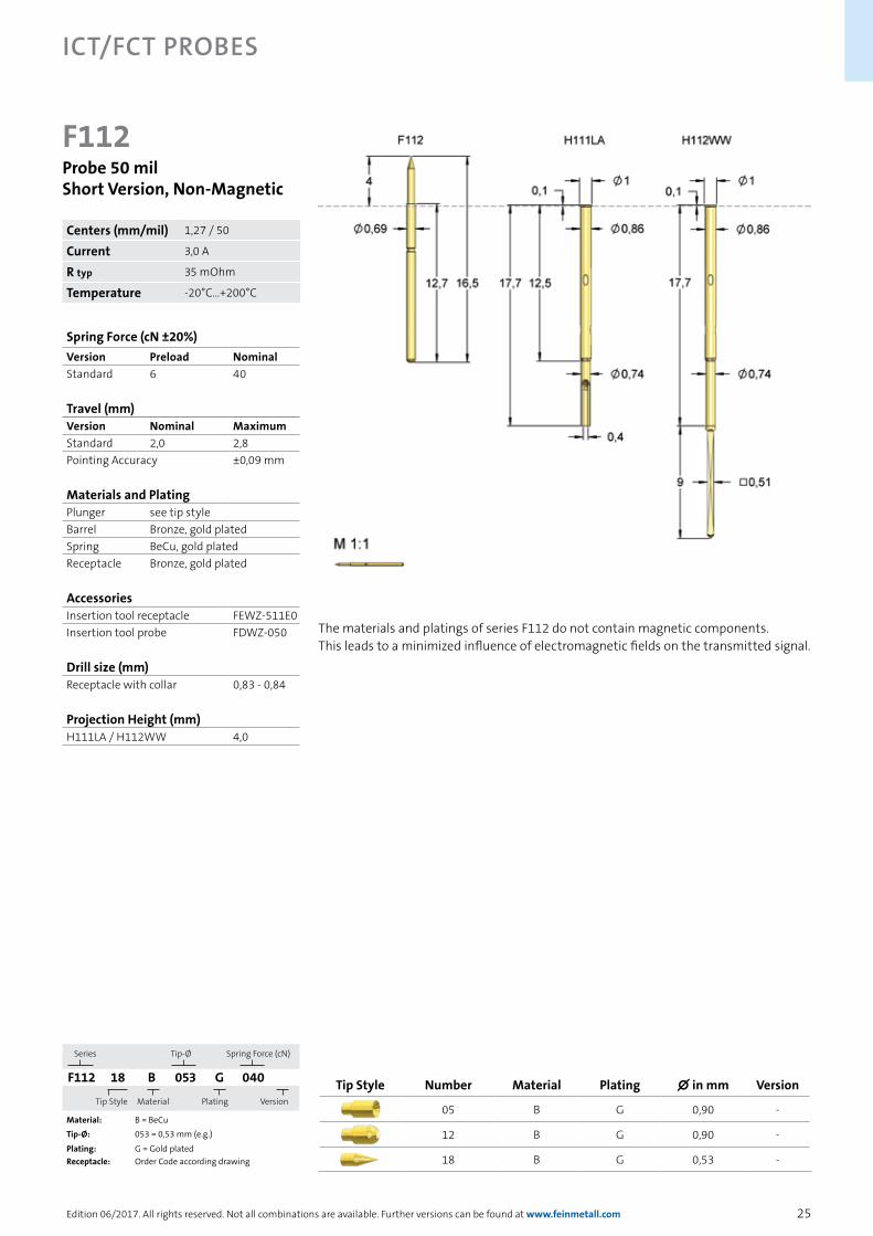
F112Probe 50 milShort Version, Non-Magnetic
Series Tip-Ø
Spring Force (cN)
F112 18 B 053 G 040
Tip Style
Material Plating
Version
Material: B = BeCuTip-Ø: 053 = 0,53 mm (e.g.)
Plating: G = Gold platedReceptacle: Order Code according drawing
The materials and platings of series F112 do not contain magnetic components. This leads to a minimized influence of electromagnetic fields on the transmitted signal.
Spring Force (cN ±20%)Version Preload NominalStandard 6 40
Travel (mm)Version Nominal MaximumStandard 2,0 2,8Pointing Accuracy ±0,09 mm
Materials and PlatingPlunger see tip styleBarrel Bronze, gold platedSpring BeCu, gold platedReceptacle Bronze, gold plated
AccessoriesInsertion tool receptacle FEWZ-511E0Insertion tool probe FDWZ-050
Drill size (mm)Receptacle with collar 0,83 - 0,84
Projection Height (mm)H111LA / H112WW 4,0
Tip Style Number Material Plating ∅ in mm Version
05 B G 0,90 -
12 B G 0,90 -
18 B G 0,53 -
Centers (mm/mil) 1,27 / 50
Current 3,0 A
R typ 35 mOhm
Temperature -20°C...+200°C
26
ICT/FCT Probes
Edition 06/2017. All rights reserved. Not all combinations are available. Further versions can be found at www.feinmetall.com
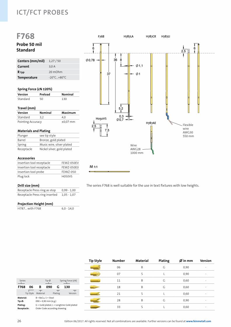
F768Probe 50 milStandard
Series Tip-Ø
Spring Force (cN)
F768 06 B 090 G 130
Tip Style
Material Plating
Version
Material: B = BeCu, S = SteelTip-Ø: 090 = 0,90 mm (e.g.)
Plating: G = Gold plated, L = Longtime Gold platedReceptacle: Order Code according drawing
The series F768 is well suitable for the use in text fixtures with low heights.
Spring Force (cN ±20%)Version Preload NominalStandard 50 130
Travel (mm)Version Nominal MaximumStandard 3,2 4,0Pointing Accuracy ±0,07 mm
Materials and PlatingPlunger see tip styleBarrel Bronze, gold platedSpring Music wire, silver platedReceptacle Nickel silver, gold plated
AccessoriesInsertion tool receptacle FEWZ-050EVInsertion tool receptacle FEWZ-050E0Insertion tool probe FDWZ-050Plug lock H050VS
Drill size (mm)Receptacle Press ring as stop 0,99 - 1,00Receptacle Press ring inserted 1,05 - 1,07
Projection Height (mm)H787... with F768 6,0 - 14,0
Tip Style Number Material Plating ∅ in mm Version
06 B G 0,90 -
07 S L 0,90 -
11 B G 0,60 -
18 B G 0,60 -
21 S L 0,60 -
28 B G 0,90 -
33 S L 0,60 -
Centers (mm/mil) 1,27 / 50
Current 3,0 A
R typ 20 mOhm
Temperature -20°C...+80°C
WireAWG281000 mm
Flexible wireAWG30550 mm

27
ICT/FCT Probes
Edition 06/2017. All rights reserved. Not all combinations are available. Further versions can be found at www.feinmetall.com
F788Probe 50 milLong Travel Version
Series Tip-Ø
Spring Force (cN)
F788 33 S 050 L 165 L
Tip Style
Material Plating
Version
Material: B = BeCu, S = SteelTip-Ø: 050 = 0,50 mm (e.g.)
Plating: G = Gold plated, L = Longtime Gold platedVersion: L = Long versionReceptacle: Order Code according drawing
The F788 is the long travel version of the F768. These probes can be combined well in dual stage fixtures. Also available: receptacle H050WL11/7.6 with spring loaded end for contacting conductor paths.
Spring Force (cN ±20%)Version Preload NominalStandard 30 165L 30 165
Travel (mm)Version Nominal MaximumStandard 6,4 7,0L 6,4 7,0Pointing Accuracy ±0,10 mm
Materials and PlatingPlunger see tip styleBarrel Bronze, gold platedSpring Music wire, silver platedReceptacle Nickel silver, gold plated
AccessoriesInsertion tool receptacle FEWZ-050EVInsertion tool receptacle FEWZ-050E0Insertion tool probe FDWZ-050Plug lock H050VS
Drill size (mm)Receptacle Press ring as stop 0,99 - 1,00Receptacle Press ring inserted 1,05 - 1,07
Projection Height (mm)H787... with F788 12,0 - 20,0H787... with F788...L 14,0 - 22,0
Centers (mm/mil) 1,27 / 50
Current 3,0 A
R typ 20 mOhm
Temperature -20°C...+80°C
Tip Style Number Material Plating ∅ in mm Version
06 B G 0,90 -
07 S L 0,90 -
11 B G 0,60 -
18 B G 0,60 -
33 S L 0,60 -
33 S L 0,50 L
WireAWG281000 mm
Flexible wireAWG30550 mm
28
ICT/FCT Probes
Edition 06/2017. All rights reserved. Not all combinations are available. Further versions can be found at www.feinmetall.com
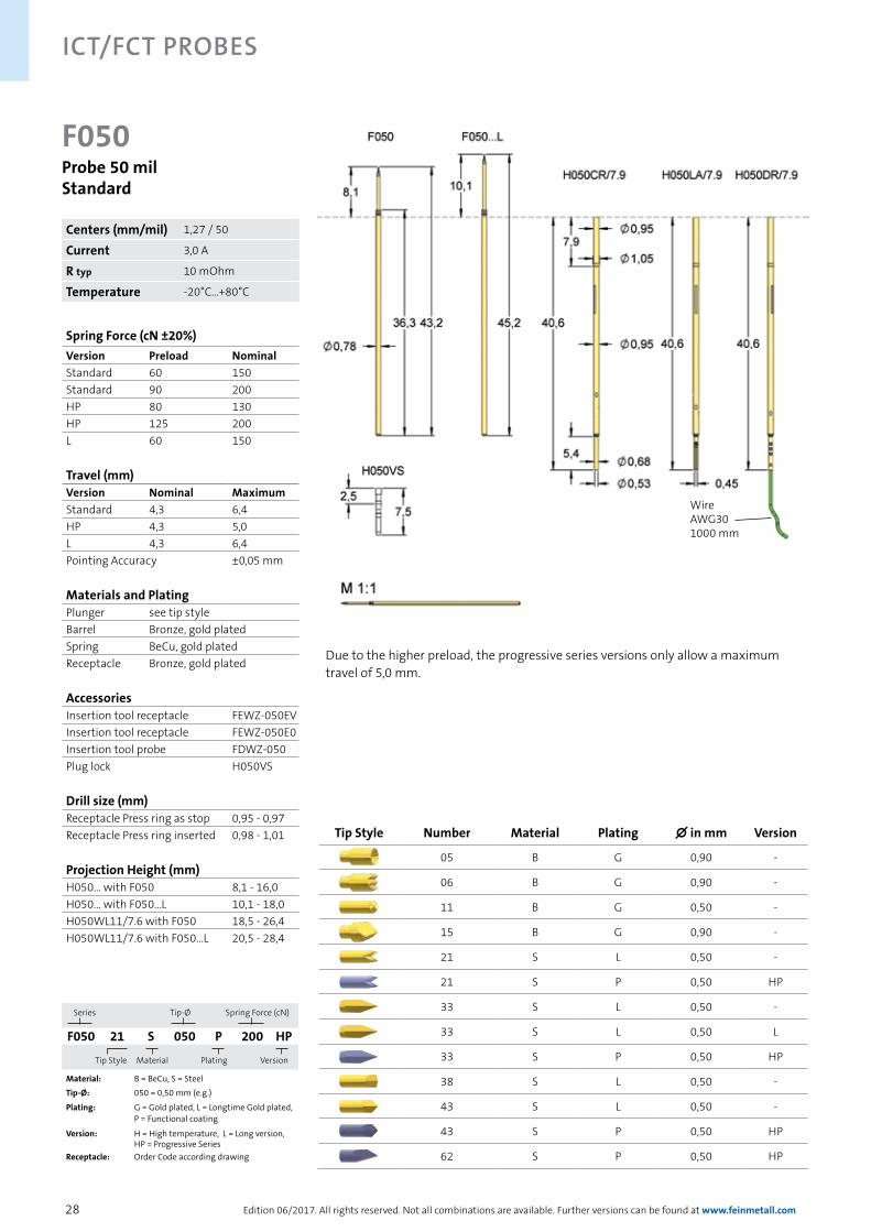
F050Probe 50 milStandard
Series Tip-Ø
Spring Force (cN)
F050 21 S 050 P 200 HP
Tip Style
Material Plating
Version
Material: B = BeCu, S = SteelTip-Ø: 050 = 0,50 mm (e.g.)
Plating: G = Gold plated, L = Longtime Gold plated, P = Functional coating
Version: H = High temperature, L = Long version,HP = Progressive Series
Receptacle: Order Code according drawing
Due to the higher preload, the progressive series versions only allow a maximum travel of 5,0 mm.
Spring Force (cN ±20%)Version Preload NominalStandard 60 150Standard 90 200HP 80 130HP 125 200L 60 150
Travel (mm)Version Nominal MaximumStandard 4,3 6,4HP 4,3 5,0L 4,3 6,4Pointing Accuracy ±0,05 mm
Materials and PlatingPlunger see tip styleBarrel Bronze, gold platedSpring BeCu, gold platedReceptacle Bronze, gold plated
AccessoriesInsertion tool receptacle FEWZ-050EVInsertion tool receptacle FEWZ-050E0Insertion tool probe FDWZ-050Plug lock H050VS
Drill size (mm)Receptacle Press ring as stop 0,95 - 0,97Receptacle Press ring inserted 0,98 - 1,01
Projection Height (mm)H050... with F050 8,1 - 16,0H050... with F050...L 10,1 - 18,0H050WL11/7.6 with F050 18,5 - 26,4H050WL11/7.6 with F050...L 20,5 - 28,4
Tip Style Number Material Plating ∅ in mm Version
05 B G 0,90 -
06 B G 0,90 -
11 B G 0,50 -
15 B G 0,90 -
21 S L 0,50 -
21 S P 0,50 HP
33 S L 0,50 -
33 S L 0,50 L
33 S P 0,50 HP
38 S L 0,50 -
43 S L 0,50 -
43 S P 0,50 HP
62 S P 0,50 HP
Centers (mm/mil) 1,27 / 50
Current 3,0 A
R typ 10 mOhm
Temperature -20°C...+80°C
WireAWG301000 mm
29
ICT/FCT Probes
Edition 06/2017. All rights reserved. Not all combinations are available. Further versions can be found at www.feinmetall.com
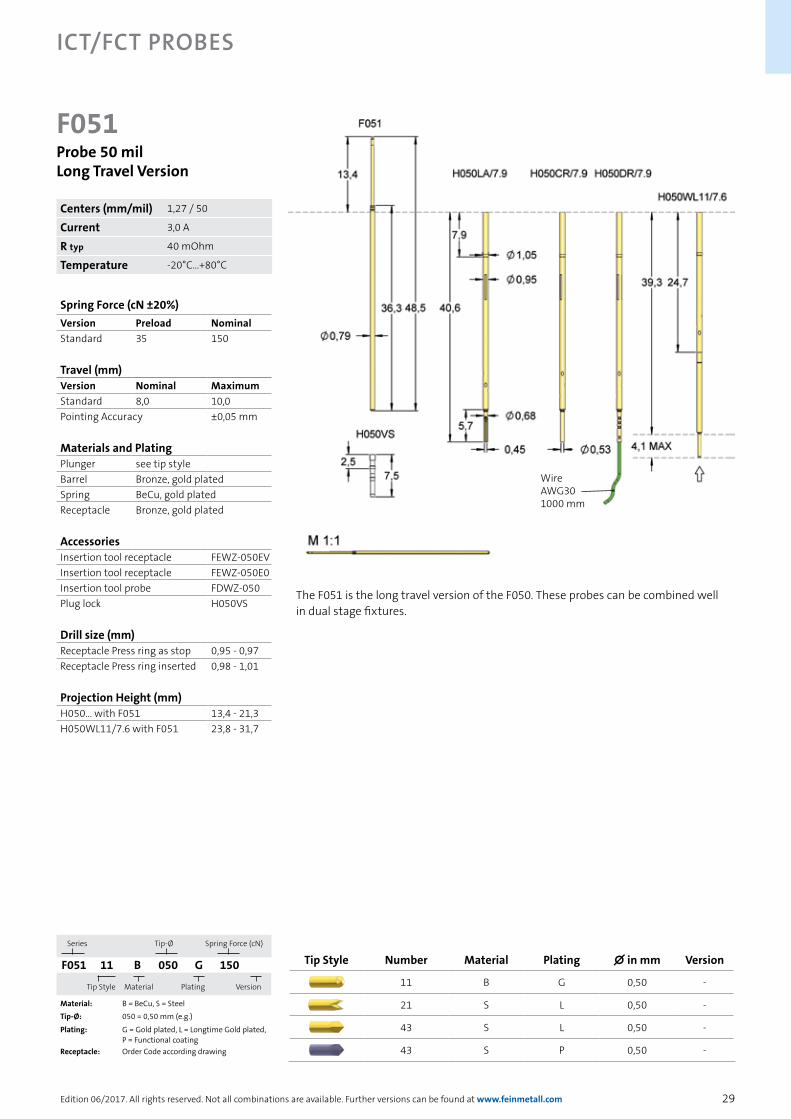
F051Probe 50 milLong Travel Version
Series Tip-Ø
Spring Force (cN)
F051 11 B 050 G 150
Tip Style
Material Plating
Version
Material: B = BeCu, S = SteelTip-Ø: 050 = 0,50 mm (e.g.)
Plating: G = Gold plated, L = Longtime Gold plated, P = Functional coating
Receptacle: Order Code according drawing
The F051 is the long travel version of the F050. These probes can be combined wellin dual stage fixtures.
Spring Force (cN ±20%)Version Preload NominalStandard 35 150
Travel (mm)Version Nominal MaximumStandard 8,0 10,0Pointing Accuracy ±0,05 mm
Materials and PlatingPlunger see tip styleBarrel Bronze, gold platedSpring BeCu, gold platedReceptacle Bronze, gold plated
AccessoriesInsertion tool receptacle FEWZ-050EVInsertion tool receptacle FEWZ-050E0Insertion tool probe FDWZ-050Plug lock H050VS
Drill size (mm)Receptacle Press ring as stop 0,95 - 0,97Receptacle Press ring inserted 0,98 - 1,01
Projection Height (mm)H050... with F051 13,4 - 21,3H050WL11/7.6 with F051 23,8 - 31,7
Tip Style Number Material Plating ∅ in mm Version
11 B G 0,50 -
21 S L 0,50 -
43 S L 0,50 -
43 S P 0,50 -
Centers (mm/mil) 1,27 / 50
Current 3,0 A
R typ 40 mOhm
Temperature -20°C...+80°C
WireAWG301000 mm

30
ICT/FCT Probes
Edition 06/2017. All rights reserved. Not all combinations are available. Further versions can be found at www.feinmetall.com
F561Probe 75 milShort Version
Series Tip-Ø
Spring Force (cN)
F561 05 B 150 G 150
Tip Style
Material Plating
Version
Material: B = BeCuTip-Ø: 150 = 1,50 mm (e.g.)
Plating: G = Gold platedReceptacle: Order Code according drawing
The F561 is the short version of probes for 75 mil centers.
Spring Force (cN ±20%)Version Preload NominalStandard 30 80Standard 50 100Standard 70 150
Travel (mm)Version Nominal MaximumStandard 2,4 3,0Pointing Accuracy ±0,05 mm
Materials and PlatingPlunger see tip styleBarrel Bronze, gold platedSpring Music wire, silver platedReceptacle Nickel silver, gold plated
AccessoriesInsertion tool receptacle FEWZ-075EVInsertion tool receptacle FEWZ-075E0Insertion tool probe FDWZ-075Plug lock H075VS
Drill size (mm)Receptacle Press ring as stop 1,29 - 1,30Receptacle Press ring inserted 1,36 - 1,40
Projection Height (mm)H561... with F561 4,5 - 8,4
Tip Style Number Material Plating ∅ in mm Version
05 B G 1,50 -
06 B G 1,50 -
11 B G 0,50 -
15 B G 1,50 -
18 B G 0,50 -
Centers (mm/mil) 1,90 / 75
Current 4,0 A
R typ 20 mOhm
Temperature -20°C...+80°C

31
ICT/FCT Probes
Edition 06/2017. All rights reserved. Not all combinations are available. Further versions can be found at www.feinmetall.com
F701
Tip Style Number Material Plating ∅ in mm Version
06 B G 1,15 -
07 S L 1,15 -
11 B G 0,50 -
14 S L 1,15 -
15 B G 1,30 -
18 B G 0,50 -
21 S L 0,50 -
Probe 75 milShort Version
Series Tip-Ø
Spring Force (cN)
F701 06 B 115 G 150
Tip Style
Material Plating
Version
Material: B = BeCu, S = SteelTip-Ø: 115 = 1,15 mm (e.g.)
Plating: G = Gold plated, L = Longtime Gold platedReceptacle: Order Code according drawing
Spring Force (cN ±20%)Version Preload NominalStandard 15 40Standard 40 70Standard 30 150
Travel (mm)Version Nominal MaximumStandard 4,0 5,0Pointing Accuracy ±0,10 mm
Materials and PlatingPlunger see tip styleBarrel Bronze, gold platedSpring Music wire, silver platedReceptacle Bronze, gold plated
AccessoriesInsertion tool receptacle FEWZ-075EVInsertion tool receptacle FEWZ-075E0Insertion tool probe FDWZ-075Plug lock H075VS
Drill size (mm)Receptacle with collar 1,31 - 1,32
Projection Height (mm)H701CR/LA with F701 12,5H701WW with F701 12,7
Centers (mm/mil) 1,90 / 75
Current 4,0 A
R typ 20 mOhm
Temperature -20°C...+80°C

32
ICT/FCT Probes
Edition 06/2017. All rights reserved. Not all combinations are available. Further versions can be found at www.feinmetall.com
Insulating Caps OverviewExact dimensions and technical details can be found in the respective series.
F075 Order ExampleSpring ForceInner-Ø AOuter-Ø BOverlap C
F07506B130G200IK04200 cN
Ø 1,30 mmØ 1,70 mm
0,40 mm
F786 Order ExampleSpring ForceInner-Ø AOuter-Ø BOverlap C
F78606B400G300IK06300 cN
Ø 4,00 mmØ 4,80 mm
0,60 mm
F78606B400G300IK17300 cN
Ø 4,00 mmØ 4,80 mm
1,70 mm
F772 Order ExampleSpring ForceInner-Ø AOuter-Ø BOverlap C
F77206B120G150IK05 150 cN
Ø 1,20 mmØ 2,00 mm
0,50 mm
F77206B180G150IK08 150 cN
Ø 1,80 mmØ 2,60 mm
0,8 mm
F77206B200G150IK05
150 cNØ 2,00 mmØ 2,80 mm
0,50 mm
F588 Order ExampleSpring ForceInner-Ø AOuter-Ø BOverlap C
F58841B150G300IK 300 cN
Ø 1,50 mmØ 2,20 mm
0,40 mm
F58841B150G300IK04S 300 cN
Ø 1,50 mmØ 2,20 mm
0,40 mm
F100 Order ExampleSpring ForceInner-Ø AOuter-Ø BOverlap C
F10005B150G100IK04100 cN
Ø 1,50 mmØ 2,20 mm
0,40 mm
F100 Order ExampleSpring ForceInner-Ø AOuter-Ø BOverlap C
F10006B150GxxxIK04100, 200, 300 cN
Ø 1,50 mmØ 2,20 mm
0,40 mm
F100 Order ExampleSpring ForceInner-Ø AOuter-Ø BOverlap C
F10006B200GxxxIK04200, 300 cNØ 2,00 mmØ 3,20 mm
0,40 mm
F10006B350GxxxIK04200, 300 cNØ 3,50 mmØ 4,00 mm
0,40 mm
F10006B350G300IK10300 cN
Ø 3,50 mmØ 4,20 mm
1,00 mm
F100 Order ExampleSpring ForceInner-Ø AOuter-Ø BOverlap C
F10006B370G300IK36300 cN
Ø 3,70 mmØ 4,40 mm
3,60 mm
F10017B150G200IK04200 cN
Ø 1,50 mmØ 2,20 mm
0,40 mm
F10041B150GxxxIK04200, 300 cNØ 1,50 mmØ 2,20 mm
0,40 mm

33
ICT/FCT Probes
Edition 06/2017. All rights reserved. Not all combinations are available. Further versions can be found at www.feinmetall.com
Tip Style Number Material Plating ∅ in mm Version
21 S P 0,64 HP
21 S P 0,64 HPL
32 S P 0,64 HP
32 S P 0,64 HPL
33 S P 0,64 HP
33 S P 0,64 HPL
43 S P 0,64 HP
43 S P 0,64 HPL
62 S P 0,64 HP
62 S P 0,64 HPL
F075...HPProbe 75 milProgressive Series
Series Tip-Ø
Spring Force (cN)
F075 21 S 064 P 200 HP
Tip Style
Material Plating
Version
Material: S = Steel
Tip-Ø: 064 = 0,64 mm (e.g.)
Plating: P = Functional coating
Version: HP = Progressive Series, HPL = Progressive Series Long version
Receptacle: Order Code according drawing
This series was developed for difficult contacting conditions such as lead free soldered pads or strongly contaminated or oxidized boards. Probes of this series allow penetrating sticky layers reliably with a low vulnerability to contaminations of the tips. This leads to a high contact reliability and a long life time of these probes.
Spring Force (cN ±20%)Version Preload NominalHP 120 200HP 130 250HPL 120 200HPL 130 250
Travel (mm)Version Nominal MaximumHP 4,3 6,4HPL 4,3 6,4Pointing Accuracy ±0,08 mm
Materials and PlatingPlunger see tip styleBarrel Bronze, gold platedSpring Music wire, gold platedReceptacle Nickel silver, gold plated
AccessoriesInsertion tool receptacle FEWZ-075EVInsertion tool receptacle FEWZ-075E0Insertion tool probe FDWZ-075Plug lock H075VS
Drill size (mm)Receptacle Press ring as stop 1,29 - 1,30Receptacle Press ring inserted 1,36 - 1,40
Projection Height (mm)(F075) H075.../10.0 8,4 - 18,4(F075) H075.../7.6 8,4 - 16,0(F075) H075.../2.0 8,4 - 10,4(F075) H075WW10/2.0S1 11,4 - 13,4(F075) H075WW10/2.0S2 16,4 - 18,4(F075...L) H075.../10.0 10,4 - 20,4(F075...L) H075.../7.6 10,4 - 18,0(F075...L) H075.../2.0 10,4 - 12,4(F075...L) H075WW10/2.0S1 13,4 - 15,4(F075...L) H075WW10/2.0S2 18,4 - 20,4
Centers (mm/mil) 1,90 / 75
Current 4,0 A
R typ 40 mOhm
Temperature -20°C...+80°C

34
ICT/FCT Probes
Edition 06/2017. All rights reserved. Not all combinations are available. Further versions can be found at www.feinmetall.com
Tip Style Number Material Plating ∅ in mm Version
05 B G 1,20 -
06 B G 1,00 -
06 B G 1,20 -
06 B G 1,30 IK
07 S L 1,20 -
10 S L 0,64 -
11 B G 0,64 -
14 S L 0,78 -
14 S L 1,20 -
15 B G 0,90 -
15 B G 1,20 -
15 B G 1,20 L
17 B G 1,20 -
18 B G 0,78 -
21 S L 0,64 -
21 S L 0,64 L
30 S L 0,64 -
33 S L 0,64 -
33 S L 0,64 L
F075Probe 75 milStandard
Series Tip-Ø
Spring Force (cN)
F075 05 B 150 G 200 L
Tip Style
Material Plating
Version
Material: B = BeCu, S = Steel
Tip-Ø: 150 = 1,50 mm (e.g.)
Plating: G = Gold plated, L = Longtime Gold plated
Version: L = Long version, IK = Insulation cap
Receptacle: Order Code according drawing
Probe series F075 is the most common probe for 75 mil centers. Further information about the receptacles see extra section for receptacle H075.
Spring Force (cN ±20%)Version Preload NominalStandard 30 60Standard 50 100Standard 70 150Standard 80 200Standard 100 280L 50 100L 70 150L 80 200L 100 280IK 30 60IK 70 150IK 70 280
Travel (mm)Version Nominal MaximumStandard 4,3 6,4L 4,3 6,4IK 4,3 6,4Pointing Accuracy ±0,08 mm
Materials and PlatingPlunger see tip styleBarrel Bronze, gold platedSpring Music wire, silver platedReceptacle Nickel silver, gold plated
AccessoriesInsertion tool receptacle FEWZ-075EVInsertion tool receptacle FEWZ-075E0Insertion tool probe FDWZ-075Plug lock H075VS
Drill size (mm)Receptacle Press ring as stop 1,29 - 1,30Receptacle Press ring inserted 1,36 - 1,40
Centers (mm/mil) 1,90 / 75
Current 4,0 A
R typ 50 mOhm
Temperature -20°C...+80°C

35
ICT/FCT Probes
Edition 06/2017. All rights reserved. Not all combinations are available. Further versions can be found at www.feinmetall.com
Series Length of Wire Wrap Pin
H 075 WW 10 / 7.6
Connection Type
Press Ring Position
Connection Type: CR= Crimp connectionLA = Solder connectionWW = Wire Wrap connectionLI = Stranded wireWL = Spring loaded connection
Length of Wire Wrap Pin: e.g. 10 = 10,0 mm
Press Ring Position: e.g. 7.6 = 7,6 mm
H075Receptacle 75 mil
Materials and PlatingReceptacle Nickel silver, gold plated
AccessoriesInsertion tool receptacle FEWZ-075EVInsertion tool receptacle FEWZ-075E0
Drill size (mm)Receptacle Press ring as stop 1,29 - 1,30Receptacle Press ring inserted 1,36 - 1,40
Tip Style Number Material Plating ∅ in mm Version
33 S L 0,78 -
36 B G 1,20 -
37 B G 0,50 -
37 B G 0,50 L
38 S L 0,64 -
38 S L 0,64 L
41 B G 1,30 IK
43 S L 0,64 -
53 S L 0,64 -
53 S L 0,64 L
63 S G 1,20 -
63 S L 1,20 -
F075Probe 75 milStandard
Projection Height (mm)(F075) H075.../10.0 8,4 - 18,4(F075) H075.../7.6 8,4 - 16,0(F075) H075.../2.0 8,4 - 10,4(F075) H075WW10/2.0S1 11,4 - 13,4(F075) H075WW10/2.0S2 16,4 - 18,4(F075...L) H075.../10.0 10,4 - 20,4(F075...L) H075.../7.6 10,4 - 18,0(F075...L) H075.../2.0 10,4 - 12,4(F075...L) H075WW10/2.0S1 13,4 - 15,4(F075...L) H075WW10/2.0S2 18,4 - 20,4

36
ICT/FCT Probes
Edition 06/2017. All rights reserved. Not all combinations are available. Further versions can be found at www.feinmetall.com
Tip Style Number Material Plating ∅ in mm Version
10 S L 0,50 RP
F075...RPWobbling Plunger for Contacting Soldered Pins
Series Tip-Ø
Spring Force (cN)
F075 10 S 050 L 100 RP
Tip Style
Material Plating
Version
Material: S = Steel
Tip-Ø: 050 = 0,50 mm (e.g.)
Plating: L = Longtime Gold plated
Version: RP = Wobbling Plunger
Receptacle: Order Code according drawing
Spring Force (cN ±20%)Version Preload NominalRP 50 100RP 70 150
Travel (mm)Version Nominal MaximumRP 4,3 6,4Pointing Accuracy ±0,08 mm
Materials and PlatingPlunger see tip styleBarrel Bronze, gold platedSpring Music wire, silver platedReceptacle Nickel silver, gold plated
AccessoriesInsertion tool receptacle FEWZ-075EVInsertion tool receptacle FEWZ-075E0Insertion tool probe FDWZ-075Plug lock H075VS
The deflection of a wobbling plunger substantially exceeds the function of the flexible needle. The special design of the plunger enables plunger deflections without notable abrasion. High level stress tests with plunger deflection up to 0.8 mm have resulted in outstanding electrical performance and life time of the probe. The diagram shows the comparison to a conventional probe without wobbling plunger.
Centers (mm/mil) 1,90 / 75
Current 4,0 A
R typ 50 mOhm
Temperature -20°C...+80°C
Resi
stan
ce [m
Ohm
]
Life cycles
37
ICT/FCT Probes
Edition 06/2017. All rights reserved. Not all combinations are available. Further versions can be found at www.feinmetall.com
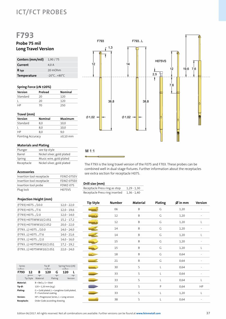
F793Probe 75 milLong Travel Version
Series Tip-Ø
Spring Force (cN)
F793 12 B 120 G 120 L
Tip Style
Material Plating
Version
Material: B = BeCu, S = Steel
Tip-Ø: 120 = 1,20 mm (e.g.)
Plating: G = Gold plated, L = Longtime Gold plated, P = Functional coating
Version: HP = Progressive Series, L = Long version
Receptacle: Order Code according drawing
The F793 is the long travel version of the F075 and F703. These probes can be combined well in dual stage fixtures. Further information about the receptacles see extra section for receptacle H075.
Spring Force (cN ±20%)Version Preload NominalStandard 20 120L 20 120HP 70 250
Travel (mm)Version Nominal MaximumStandard 8,0 10,0L 8,0 10,0HP 8,0 9,0Pointing Accuracy ±0,10 mm
Materials and PlatingPlunger see tip styleBarrel Nickel silver, gold platedSpring Music wire, gold platedReceptacle Nickel silver, gold plated
AccessoriesInsertion tool receptacle FEWZ-075EVInsertion tool receptacle FEWZ-075E0Insertion tool probe FDWZ-075Plug lock H075VS
Projection Height (mm)
(F793) H075.../10.0 12,0 - 22,0
(F793) H075.../7.6 12,0 - 19,6
(F793) H075.../2.0 12,0 - 14,0
(F793) H075WW10/2.0S1 15,2 - 17,2
(F793) H075WW10/2.0S2 20,0 - 22,0
(F793...L) H075.../10.0 14,0 - 24,0
(F793...L) H075.../7.6 14,0 - 21,6
(F793...L) H075.../2.0 14,0 - 16,0
(F793...L) H075WW10/2.0S1 17,2 - 19,2
(F793...L) H075WW10/2.0S1 22,0 - 24,0
Tip Style Number Material Plating ∅ in mm Version
06 B G 1,20 -
12 B G 1,20 -
12 B G 1,20 L
14 B G 1,20 -
14 B G 1,20 L
15 B G 1,20 -
15 B G 1,20 L
18 B G 0,64 -
21 B G 0,64 -
30 S L 0,64 -
33 S L 0,64 -
33 S L 0,64 L
33 S P 0,64 HP
33 S L 1,20 L
38 S L 0,64 -
Drill size (mm)Receptacle Press ring as stop 1,29 - 1,30Receptacle Press ring inserted 1,36 - 1,40
Centers (mm/mil) 1,90 / 75
Current 4,0 A
R typ 20 mOhm
Temperature -20°C...+80°C
38
ICT/FCT Probes
Edition 06/2017. All rights reserved. Not all combinations are available. Further versions can be found at www.feinmetall.com
Tip Style Number Material Plating ∅ in mm Version
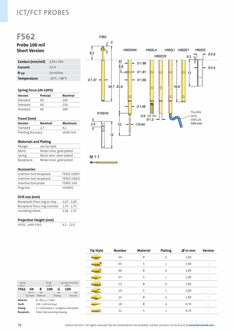
04 B G 1,90 -
05 S L 1,90 -
06 B G 1,90 -
07 S L 1,90 -
12 B G 1,90 -
14 S L 1,90 -
15 B G 1,90 -
18 B G 0,76 -
21 S L 0,76 -
F562Probe 100 milShort Version
Series Tip-Ø
Spring Force (cN)
F562 04 B 190 G 100
Tip Style
Material Plating
Version
Material: B = BeCu, S = Steel
Tip-Ø: 190 = 1,90 mm (e.g.)
Plating: G = Gold plated, L = Longtime Gold plated
Receptacle: Order Code according drawing
Spring Force (cN ±20%)Version Preload NominalStandard 60 100Standard 60 150Standard 60 200
Travel (mm)Version Nominal MaximumStandard 2,7 4,1Pointing Accuracy ±0,05 mm
Materials and PlatingPlunger see tip styleBarrel Nickel silver, gold platedSpring Music wire, silver platedReceptacle Nickel silver, gold plated
AccessoriesInsertion tool receptacle FEWZ-100EVInsertion tool receptacle FEWZ-100E0Insertion tool probe FDWZ-100Plug lock H100VS
Drill size (mm)Receptacle Press ring as stop 1,67 - 1,69Receptacle Press ring inserted 1,70 - 1,75Insulating sleeve 2,36 - 2,37
Projection Height (mm)H502... with F562 6,2 - 12,0
Centers (mm/mil) 2,54 / 100
Current 5,0 A
R typ 20 mOhm
Temperature -20°C...+80°C
Flexible wireAWG26550 mm
39
ICT/FCT Probes
Edition 06/2017. All rights reserved. Not all combinations are available. Further versions can be found at www.feinmetall.com
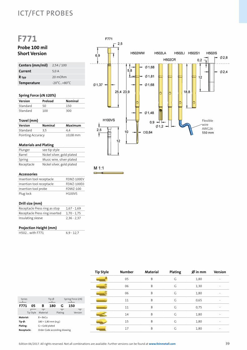
Tip Style Number Material Plating ∅ in mm Version
05 B G 1,80 -
06 B G 1,30 -
06 B G 1,80 -
11 B G 0,65 -
11 B G 0,75 -
14 B G 1,80 -
15 B G 1,80 -
17 B G 1,80 -
F771Probe 100 milShort Version
Series Tip-Ø
Spring Force (cN)
F771 05 B 180 G 150
Tip Style
Material Plating
Version
Material: B = BeCu
Tip-Ø: 180 = 1,80 mm (e.g.)
Plating: G = Gold plated
Receptacle: Order Code according drawing
Spring Force (cN ±20%)Version Preload NominalStandard 50 150Standard 100 300
Travel (mm)Version Nominal MaximumStandard 3,5 4,4Pointing Accuracy ±0,08 mm
Materials and PlatingPlunger see tip styleBarrel Nickel silver, gold platedSpring Music wire, silver platedReceptacle Nickel silver, gold plated
AccessoriesInsertion tool receptacle FEWZ-100EVInsertion tool receptacle FEWZ-100E0Insertion tool probe FDWZ-100Plug lock H100VS
Drill size (mm)Receptacle Press ring as stop 1,67 - 1,69Receptacle Press ring inserted 1,70 - 1,75Insulating sleeve 2,36 - 2,37
Projection Height (mm)H502... with F771 6,9 - 12,7
Centers (mm/mil) 2,54 / 100
Current 5,0 A
R typ 20 mOhm
Temperature -20°C...+80°C
Flexible wireAWG26550 mm

40
ICT/FCT Probes
Edition 06/2017. All rights reserved. Not all combinations are available. Further versions can be found at www.feinmetall.com
F100Probe 100 milStandard
Series Tip-Ø
Spring Force (cN)
F100 06 B 150 G 100 L
Tip Style
Material Plating
Version
Material: B = BeCu, S = Steel
Tip-Ø: 150 = 1,50 mm (e.g.)
Plating: G = Gold plated, L = Longtime Gold plated
Version: L = Long version, IK = Insulation cap
Receptacle: Order Code according drawing
Probe series F100 is the most common probe for 100 mil centers. Further information about the receptacles see extra section for receptacle H100.
Spring Force (cN ±20%)Version Preload NominalStandard 30 60Standard 40 100Standard 80 150Standard 80 200Standard 150 300Standard 180 400H 70 150H 70 200H 100 300L 40 100L 80 150L 80 200L 150 300Mint-Pin 40 100Mint-Pin 80 150Mint-Pin 60 225
Travel (mm)Version Nominal MaximumStandard 4,3 6,4L 4,3 6,4Mint-Pin 4,3 6,4Pointing Accuracy ±0,08 mm
Materials and PlatingPlunger see tip styleBarrel Nickel silver, gold platedSpring Music wire, silver platedReceptacle Nickel silver, gold plated
AccessoriesInsertion tool receptacle FEWZ-100EVInsertion tool receptacle FEWZ-100E0Insertion tool probe FDWZ-100Plug lock H100VS
Tip Style Number Material Plating ∅ in mm Version
05 B G 1,50 -
06 B G 1,30 -
06 B G 1,30 H
06 B G 1,50 -
06 B G 1,50 H
06 B G 1,50 L
06 B G 2,00 -
06 B G 2,50 -
06 B G 3,00 -
06 B G 3,10 Mint-Pin
06 B G 4,00 -
07 S L 1,50 -
07 S L 1,50 H
11 B G 0,50 -
11 B G 0,64 -
11 B G 0,90 -
11 B G 0,90 H
11 B G 0,90 L
Centers (mm/mil) 2,54 / 100
Current 5,0 A
R typ 20 mOhm
Temperature -20°C...+80°C-40°C...+200°C (H)

41
ICT/FCT Probes
Edition 06/2017. All rights reserved. Not all combinations are available. Further versions can be found at www.feinmetall.com
Drill size (mm)Receptacle Press ring as stop 1,67 - 1,69Receptacle Press ring inserted 1,70 - 1,75
Projection Height (mm)(F100) H100.../10.0 8,4 - 18,4(F100) H100.../7.6 8,4 - 16,0(F100) H100.../2.0 8,4 - 10,4(F100) H100WW10/2.0S1 11,4 - 13,4(F100) H100WW10/2.0S2 16,4 - 18,4(F100...L) H100.../10.0 10,4 - 20,4(F100...L) H100.../7.6 10,4 - 18,0(F100...L) H100.../2.0 10,4 - 12,4(F100...L) H100WW10/2.0S1 13,4 - 15,4(F100...L) H100WW10/2.0S2 18,4 - 20,4
F100Probe 100 milStandard
Tip Style Number Material Plating ∅ in mm Version
12 B G 1,50 -
14 B G 1,30 -
14 B G 1,50 -
14 S L 1,30 -
14 S L 1,30 H
14 S L 1,50 H
14 S L 1,50 -
15 B G 1,50 -
15 B G 1,50 L
15 B G 1,50 H
15 B G 1,70 -
15 B G 2,50 H
17 B G 1,50 -
17 B G 2,00 -
17 B G 2,00 H
18 B G 0,90 -
21 S L 0,90 -
21 S L 0,90 L
30 B G 0,90 -
33 S L 0,90 -
33 S L 0,90 H
33 S L 0,90 L
35 S L 1,50 -
36 S L 1,30 -
36 S L 1,30 H
37 S L 0,50 -
38 S L 0,90 -
43 S L 0,90 -
53 S L 0,90 -
53 S L 0,90 L
55 B G 1,80 -
55 B G 1,80 H
55 B G 1,80 L
62 B G 0,90 -
62 B G 0,90 H
63 B G 1,50 -
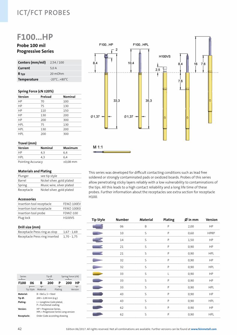
42
ICT/FCT Probes
Edition 06/2017. All rights reserved. Not all combinations are available. Further versions can be found at www.feinmetall.com
F100...HPProbe 100 milProgressive Series
Series Tip-Ø
Spring Force (cN)
F100 06 B 200 P 200 HP
Tip Style
Material Plating
Version
Material: B = BeCu, S = Steel
Tip-Ø: 200 = 2,00 mm (e.g.)
Plating: L = Longtime Gold plated, P = Functional coating
Version: HP = Progressive Series, HPL = Progressive Series Long version
Receptacle: Order Code according drawing
This series was developed for difficult contacting conditions such as lead free soldered or strongly contaminated pads or oxidized boards. Probes of this series allow penetrating sticky layers reliably with a low vulnerability to contaminations of the tips. All this leads to a high contact reliability and a long life time of these probes. Further information about the receptacles see extra section for receptacle H100.
Spring Force (cN ±20%)Version Preload NominalHP 70 100HP 75 130HP 110 150HP 130 200HP 200 300HPL 75 130HPL 130 200HPL 200 300
Travel (mm)Version Nominal MaximumHP 4,3 6,4HPL 4,3 6,4Pointing Accuracy ±0,08 mm
Materials and PlatingPlunger see tip styleBarrel Nickel silver, gold platedSpring Music wire, silver platedReceptacle Nickel silver, gold plated
AccessoriesInsertion tool receptacle FEWZ-100EVInsertion tool receptacle FEWZ-100E0Insertion tool probe FDWZ-100Plug lock H100VS
Drill size (mm)Receptacle Press ring as stop 1,67 - 1,69Receptacle Press ring inserted 1,70 - 1,75
Tip Style Number Material Plating ∅ in mm Version
06 B P 2,00 HP
10 S P 0,60 HPRP
14 S P 1,50 HP
21 S P 0,90 HP
21 S P 0,90 HPL
32 S P 0,90 HP
32 S P 0,90 HPL
33 S L 0,90 HP
33 S P 0,90 HP
33 S P 0,90 HPL
43 S P 0,90 HP
43 S P 0,90 HPL
62 S P 0,90 HP
62 S P 0,90 HPL
Centers (mm/mil) 2,54 / 100
Current 5,0 A
R typ 20 mOhm
Temperature -20°C...+80°C

43
ICT/FCT Probes
Edition 06/2017. All rights reserved. Not all combinations are available. Further versions can be found at www.feinmetall.com
F100...RPWobbling Plunger for Contacting Soldered Pins
The deflection of a wobbling plunger substantially exceeds the function of the flexible needle. The special design of the plunger enables plunger deflections without notable abrasion. High level stress tests with plunger deflection up to 0.8 mm have resulted in outstanding electrical performance and life time of the probe. The diagram shows the comparison to a conventional probe without wobbling plunger. Further information about the receptacles see extra section for receptacle H100.
Tip Style Number Material Plating ∅ in mm Version
10 S L 0,60 RP
10 S P 0,60 HPRP
12 S P 105 HPRPL
Series Tip-Ø
Spring Force (cN)
F100 10 S 060 L 100 RP
Tip Style
Material Plating
Version
Material: S = Steel
Tip-Ø: 060 = 0,60 mm (e.g.)
Plating: L = Longtime Gold plated, P = Functional coating
Version: HP = Progressive Series, L = Long version, RP = Wobbling Plunger
Receptacle: Order Code according drawing
Spring Force (cN ±20%)Version Preload NominalRP 70 100RP 110 150HPRP 110 150HPRPL 200 300
Travel (mm)Version Nominal MaximumRP 4,3 6,4HPRPL 4,3 6,4Pointing Accuracy ±0,08 mm
Materials and PlatingPlunger see tip styleBarrel Nickel silver, gold platedSpring Music wire, silver platedReceptacle Nickel silver, gold plated
AccessoriesInsertion tool receptacle FEWZ-100EVInsertion tool receptacle FEWZ-100E0Insertion tool probe FDWZ-100Plug lock H100VS
Drill size (mm)Receptacle Press ring as stop 1,67 - 1,69Receptacle Press ring inserted 1,70 - 1,75
Centers (mm/mil) 2,54 / 100
Current 5,0 A
R typ 20 mOhm
Temperature -20°C...+80°C
Resi
stan
ce [m
Ohm
]
Life cycles
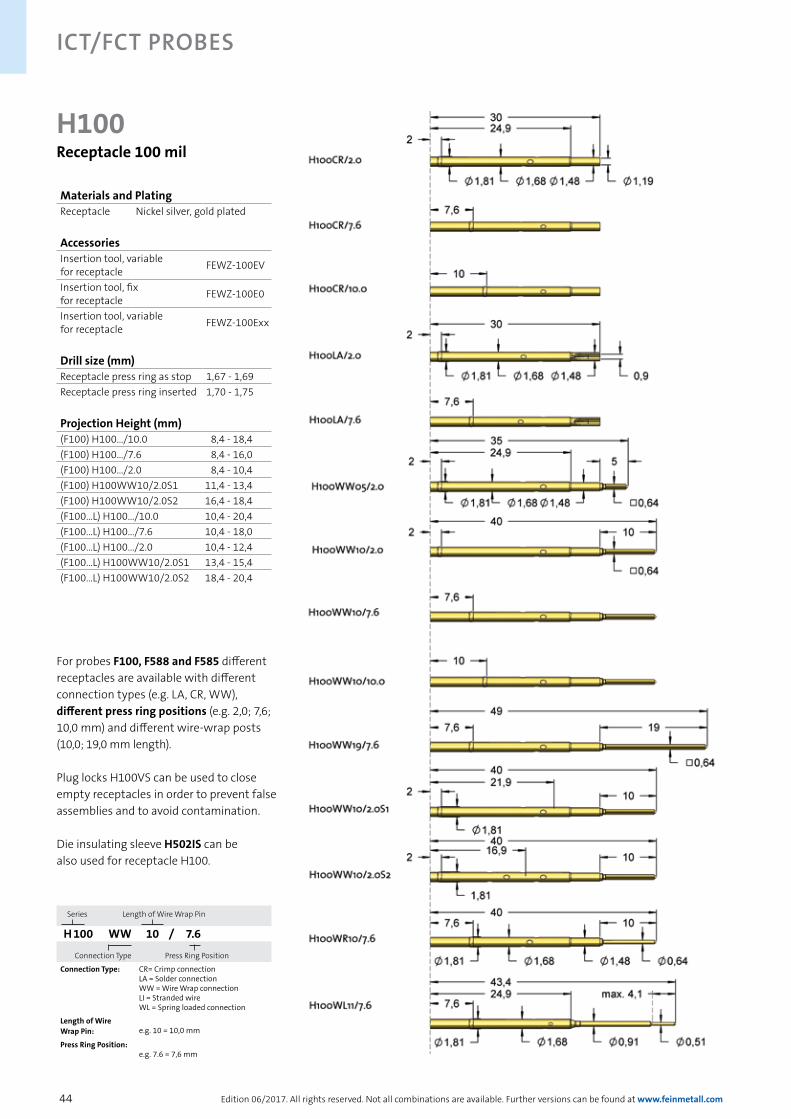
44
ICT/FCT Probes
Edition 06/2017. All rights reserved. Not all combinations are available. Further versions can be found at www.feinmetall.com
Series Length of Wire Wrap Pin
H 100 WW 10 / 7.6
Connection Type
Press Ring Position
Connection Type: CR= Crimp connectionLA = Solder connectionWW = Wire Wrap connectionLI = Stranded wireWL = Spring loaded connection
Length of Wire Wrap Pin: e.g. 10 = 10,0 mm
Press Ring Position:e.g. 7.6 = 7,6 mm
H100Receptacle 100 mil
Materials and PlatingReceptacle Nickel silver, gold plated
AccessoriesInsertion tool, variablefor receptacle FEWZ-100EV
Insertion tool, fix for receptacle FEWZ-100E0
Insertion tool, variablefor receptacle FEWZ-100Exx
Drill size (mm)Receptacle press ring as stop 1,67 - 1,69Receptacle press ring inserted 1,70 - 1,75
Projection Height (mm)(F100) H100.../10.0 8,4 - 18,4(F100) H100.../7.6 8,4 - 16,0(F100) H100.../2.0 8,4 - 10,4(F100) H100WW10/2.0S1 11,4 - 13,4(F100) H100WW10/2.0S2 16,4 - 18,4(F100...L) H100.../10.0 10,4 - 20,4(F100...L) H100.../7.6 10,4 - 18,0(F100...L) H100.../2.0 10,4 - 12,4(F100...L) H100WW10/2.0S1 13,4 - 15,4(F100...L) H100WW10/2.0S2 18,4 - 20,4
For probes F100, F588 and F585 different receptacles are available with different connection types (e.g. LA, CR, WW), different press ring positions (e.g. 2,0; 7,6; 10,0 mm) and different wire-wrap posts (10,0; 19,0 mm length).
Plug locks H100VS can be used to close empty receptacles in order to prevent false assemblies and to avoid contamination.
Die insulating sleeve H502IS can be also used for receptacle H100.

45
ICT/FCT Probes
Edition 06/2017. All rights reserved. Not all combinations are available. Further versions can be found at www.feinmetall.com
Adequate insertion tools for mounting receptacles are available. The right tool for flush insertion is FEWZ-100E0. The most economic tools for fix projection heights are FEWZ-100Exx (e.g. E55 = 5,5 mm). For variable projection heights the tool FEWZ-100EV with adjustable projection heights is appropriate.
MountingReceptacle 100 mil
Receptacles with spring loaded end are often used in interface systems. The spring loaded end of the receptacle can directly contact a PCB that is connected with the test system. For different available space these receptacles are available in different centers (50 mil, 75 mil, 100 mil).
HxxxWL11/7.6With Spring Loaded End for Interface Systems
PCB
Receptacle with spring loaded contact pin
Mounting-plate
Press ring
100 mil75 mil50 mil
H100WL11/7.6
H075WL11/7.6
H050WL11/7.6

46
ICT/FCT Probes
Edition 06/2017. All rights reserved. Not all combinations are available. Further versions can be found at www.feinmetall.com
F588Probe 100 milLong Travel Version
The F588 is the long travel version of the F100 and F585. These probes can be combined well in dual stage fixtures. Versions with insulation caps are also avail-able, see page insulation caps. Further information about the receptacles see extra section for receptacle H100.
Series Tip-Ø
Spring Force (cN)
F588 05 B 150 G 180 S
Tip Style
Material Plating
Version
Material: B = BeCu, S = Steel
Tip-Ø: 150 = 1,50 mm (e.g.)
Plating: G = Gold plated, L = Longtime Gold plated, P = Functional coating
Version: HP = Progressive Series, S = Short version
Receptacle: Order Code according drawing
Spring Force (cN ±20%)Version Preload NominalStandard 80 180Standard 110 300HP 110 180HPS 140 300S 100 180S 140 300IK 110 300
Travel (mm)Version Nominal MaximumStandard 9,3 11,7HP 9,3 11,7HPS 7,6 10,0S 7,6 10,0IK 9,3 11,7Pointing Accuracy ±0,10 mm
Materials and PlatingPlunger see tip styleBarrel Nickel silver, gold platedSpring Music wire, silver platedReceptacle Nickel silver, gold plated
AccessoriesInsertion tool receptacle FEWZ-100EVInsertion tool receptacle FEWZ-100E0Insertion tool probe FDWZ-100Plug lock H100VS
Drill size (mm)Receptacle Press ring as stop 1,67 - 1,69Receptacle Press ring inserted 1,70 - 1,75
Tip Style Number Material Plating ∅ in mm Version
05 B G 1,50 -
05 B G 1,50 S
06 B G 1,50 -
06 B G 1,50 S
11 B G 0,90 -
12 B G 1,50 -
12 B G 1,50 S
15 B G 1,50 -
15 B G 1,50 S
18 B G 0,76 -
21 S L 0,76 -
21 S L 0,90 -
21 S P 0,90 HP
28 B G 1,50 -
30 B G 0,76 -
33 S L 0,76 -
Centers (mm/mil) 2,54 / 100
Current 5,0 A
R typ 20 mOhm
Temperature -20°C...+80°C

47
ICT/FCT Probes
Edition 06/2017. All rights reserved. Not all combinations are available. Further versions can be found at www.feinmetall.com
Projection Height (mm)
(F588...S) H100.../10.0 12,4 - 22,4
(F588...S) H100.../7.6 12,4 - 20,0
(F588...S) H100.../2.0 12,4 - 14,4
(F588...S) H100WW10/2.0S1 15,4 - 17,4
(F588...S) H100WW10/2.0S2 20,4 - 22,4
(F588) H100.../10.0 14,1 - 24,1
(F588) H100.../7.6 14,1 - 21,7
(F588) H100.../2.0 14,1 - 16,1
(F588) H100WW10/2.0S1 17,1 - 19,1
(F588) H100WW10/2.0S2 22,1 - 24,1
F588Probe 100 milLong Travel Version
Tip Style Number Material Plating ∅ in mm Version
33 S L 0,76 S
33 S L 0,90 -
33 S L 0,90 S
33 S P 0,90 -
33 S P 0,90 HP
33 S P 0,90 HPS
36 S L 1,40 -
37 S L 0,50 -
37 S P 0,50 HP
38 S L 0,90 -
41 B G 1,50 IK
41 B G 1,50 IKS
43 S P 0,90 -
55 B G 1,80 -
55 B G 1,80 H
55 B G 1,80 L
62 B P 0,90 -
63 B G 1,50 -
66 B P 2,50 HP
Centers (mm/mil) 2,54 / 100
Current 5,0 A
R typ 20 mOhm
Temperature -20°C...+80°C

48
ICT/FCT Probes
Edition 06/2017. All rights reserved. Not all combinations are available. Further versions can be found at www.feinmetall.com
F772Probe 100 mil
Series Tip-Ø
Spring Force (cN)
F772 06 B 150 G 300 H
Tip Style
Material Plating
Version
Material: B = BeCu, S = Steel
Tip-Ø: 150 = 1,50 mm (e.g.)
Plating: G = Gold plated, L = Longtime Gold plated, P = Functional coating N = Nickel plated, R = Rhodium plated
Version: L = Long version, HP = Progressive Series H = High temperature, IK = Insulation cap
Receptacle: Order Code according drawing
Versions with different projection height available on request.
Spring Force (cN ±20%)Version Preload NominalStandard 30 80Standard 60 150Standard 60 220Standard 60 300H 60 150H 60 300HP 200 300
Travel (mm)Version Nominal MaximumStandard 4,0 5,0Pointing Accuracy ±0,08 mm
Materials and PlatingPlunger see tip styleBarrel Nickel silver, gold plated
Spring Music wire, silver plated, Stainless steel, unplated (H)
Receptacle Nickel silver, gold plated
AccessoriesInsertion tool receptacle FEWZ-772EVInsertion tool receptacle FEWZ-772E0Insertion tool probe FDWZ-100Plug lock H772VS
Spacers H772DS/xx for 100 mil probesOrder Code Outer-Ø Inner-Ø LengthH772DS/10 2,20 1,70 1,00H772DS/20 2,20 1,70 2,00H772DS/30 2,20 1,70 3,00H772DS/50 2,20 1,70 5,00
Centers (mm/mil) 2,54 / 100
Current 5,0 A
R typ 25 mOhm
Temperature -20°C...+80°C-40°C...+200°C (H)
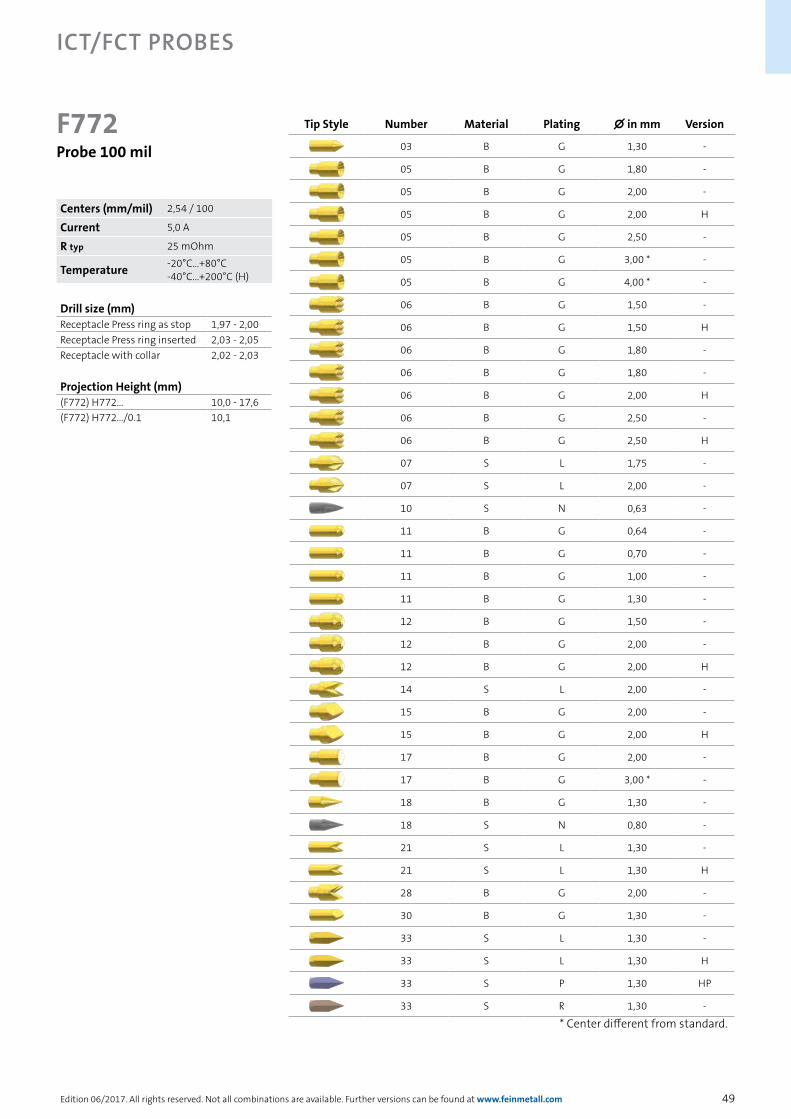
49
ICT/FCT Probes
Edition 06/2017. All rights reserved. Not all combinations are available. Further versions can be found at www.feinmetall.com
Drill size (mm)Receptacle Press ring as stop 1,97 - 2,00Receptacle Press ring inserted 2,03 - 2,05Receptacle with collar 2,02 - 2,03
Projection Height (mm)(F772) H772... 10,0 - 17,6(F772) H772.../0.1 10,1
Tip Style Number Material Plating ∅ in mm Version
03 B G 1,30 -
05 B G 1,80 -
05 B G 2,00 -
05 B G 2,00 H
05 B G 2,50 -
05 B G 3,00 * -
05 B G 4,00 * -
06 B G 1,50 -
06 B G 1,50 H
06 B G 1,80 -
06 B G 1,80 -
06 B G 2,00 H
06 B G 2,50 -
06 B G 2,50 H
07 S L 1,75 -
07 S L 2,00 -
10 S N 0,63 -
11 B G 0,64 -
11 B G 0,70 -
11 B G 1,00 -
11 B G 1,30 -
12 B G 1,50 -
12 B G 2,00 -
12 B G 2,00 H
14 S L 2,00 -
15 B G 2,00 -
15 B G 2,00 H
17 B G 2,00 -
17 B G 3,00 * -
18 B G 1,30 -
18 S N 0,80 -
21 S L 1,30 -
21 S L 1,30 H
28 B G 2,00 -
30 B G 1,30 -
33 S L 1,30 -
33 S L 1,30 H
33 S P 1,30 HP
33 S R 1,30 -
F772Probe 100 mil
* Center different from standard.
Centers (mm/mil) 2,54 / 100
Current 5,0 A
R typ 25 mOhm
Temperature -20°C...+80°C-40°C...+200°C (H)

50
ICT/FCT Probes
Edition 06/2017. All rights reserved. Not all combinations are available. Further versions can be found at www.feinmetall.com
Spacers H772DS/xx for 100 mil probesOrder Code Outer-Ø Inner-Ø LengthH772DS/10 2,20 1,70 1,00H772DS/20 2,20 1,70 2,00H772DS/30 2,20 1,70 3,00H772DS/50 2,20 1,70 5,00
Drill size (mm)Receptacle Press ring as stop 1,97 - 2,00Receptacle Press ring inserted 2,03 - 2,05Receptacle with collar 2,02 - 2,03
Projection Height (mm)(F786) H772... 16,0 - 23,6(F786) H772.../0.1 16,1
F786Probe 100 mil,Long Travel Version
Series Tip-Ø
Spring Force (cN)
F786 06 B 400 G 300 IK06
Tip Style
Material Plating
Version
Material: B = BeCu, S = Steel, K = Synthetic
Tip-Ø: 400 = 4,00 mm (e.g.)
Plating: G = Gold plated, L = Longtime Gold plated, P = Functional coating, U = Unplated
Version: HP = Progressive Series, IK = Insulation cap
Receptacle: Order Code according drawing
The F786 is the long travel version of the F772. These probes can be combined well in dual stage fixtures.
Spring Force (cN ±20%)Version Preload NominalStandard 60 150Standard 60 225Standard 60 300IK 60 300HP 180 300HP 180 500
Travel (mm)Version Nominal MaximumStandard 6,4 8,0IK 6,4 8,0HP 6,4 8,0Pointing Accuracy ±0,10 mm
Materials and PlatingPlunger see tip styleBarrel Nickel silver, gold platedSpring Music wire, silver platedReceptacle Nickel silver, gold plated
AccessoriesInsertion tool receptacle FEWZ-772EVInsertion tool receptacle FEWZ-772E0Insertion tool probe FDWZ-100Plug lock H772VS
Centers (mm/mil) 2,54 / 100
Current 5,0 A
R typ 25 mOhm
Temperature -20°C...+80°C
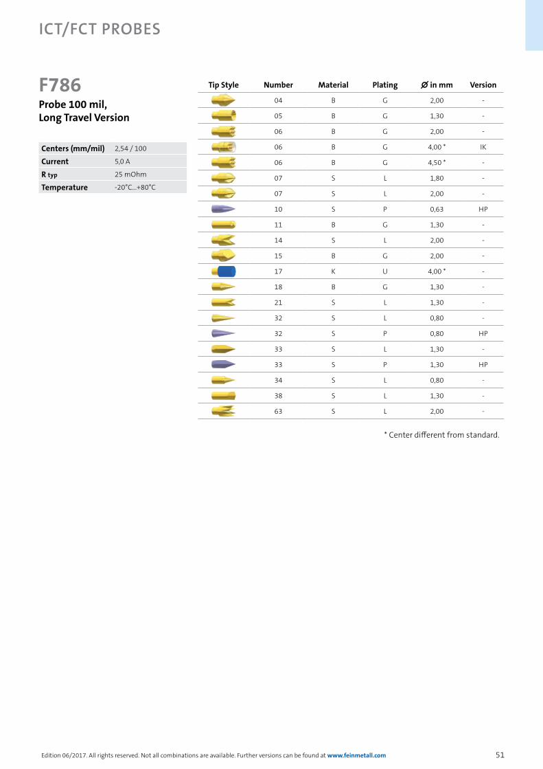
51
ICT/FCT Probes
Edition 06/2017. All rights reserved. Not all combinations are available. Further versions can be found at www.feinmetall.com
Tip Style Number Material Plating ∅ in mm Version
04 B G 2,00 -
05 B G 1,30 -
06 B G 2,00 -
06 B G 4,00 * IK
06 B G 4,50 * -
07 S L 1,80 -
07 S L 2,00 -
10 S P 0,63 HP
11 B G 1,30 -
14 S L 2,00 -
15 B G 2,00 -
17 K U 4,00 * -
18 B G 1,30 -
21 S L 1,30 -
32 S L 0,80 -
32 S P 0,80 HP
33 S L 1,30 -
33 S P 1,30 HP
34 S L 0,80 -
38 S L 1,30 -
63 S L 2,00 -
* Center different from standard.
F786Probe 100 mil,Long Travel Version
Centers (mm/mil) 2,54 / 100
Current 5,0 A
R typ 25 mOhm
Temperature -20°C...+80°C

52
ICT/FCT Probes
Edition 06/2017. All rights reserved. Not all combinations are available. Further versions can be found at www.feinmetall.com
Tip Style Number Material Plating ∅ in mm Version
06 B G 2,00 -
14 S L 2,00 -
15 B G 2,00 -
18 B G 1,00 -
18 B G 1,00 E21
63 S L 2,00 E21
Spacers H772DS/xx for 100 mil probesOrder Code Outer-Ø Inner-Ø LengthH772DS/10 2,20 1,70 1,00H772DS/20 2,20 1,70 2,00H772DS/30 2,20 1,70 3,00H772DS/50 2,20 1,70 5,00
Drill size (mm)Receptacle Press ring as stop 1,97 - 2,00Receptacle Press ring inserted 2,03 - 2,05Receptacle with collar 2,02 - 2,03
Projection Height (mm)(F797) H772... 15,0 - 22,6(F797) H772.../0.1 15,1
F797Probe 100 mil,Long Travel Version
Series Tip-Ø
Spring Force (cN)
F797 18 S 100 L 300 E21
Tip Style
Material Plating
Version
Material: B = BeCu, S = Steel, K = Synthetic
Tip-Ø: 400 = 4,00 mm (e.g.)
Plating: G = Gold plated, L = Longtime Gold plated, P = Functional coating, U = Unplated
Version: HP = Progressive Series, IK = Insulation cap
Receptacle: Order Code according drawing
The F797 is the long travel version of the F772. These probes can be combined well in dual stage fixtures.
Spring Force (cN ±20%)Version Preload NominalStandard 60 150Standard 60 300E21 100 300
Travel (mm)Version Nominal MaximumStandard 8,0 10,0E21 8,0 10,0Pointing Accuracy ±0,18 mm
Materials and PlatingPlunger see tip styleBarrel Nickel silver, gold platedSpring Music wire, silver platedReceptacle Nickel silver, gold plated
AccessoriesInsertion tool receptacle FEWZ-772EVInsertion tool receptacle FEWZ-772E0Insertion tool probe FDWZ-100Plug lock H772VS
Centers (mm/mil) 2,54 / 100
Current 5,0 A
R typ 25 mOhm
Temperature -20°C...+80°C

53
ICT/FCT Probes
Edition 06/2017. All rights reserved. Not all combinations are available. Further versions can be found at www.feinmetall.com
Drill size (mm)Press ring as stop 2,34 - 2,35Press ring inserted 2,40 - 2,45
Projection Height (mm)H563... with F563 8,4 - 16,0
F563Probe 118 mil
Series Tip-Ø
Spring Force (cN)
F563 06 B 250 G 180 HP
Tip Style
Material Plating
Version
Material: B = BeCu
Tip-Ø: 250 = 2,50 mm (e.g.)
Plating: G = Gold plated, P = Functional coating
Version: HP = Progressive Series
Receptacle: Order Code according drawing
A long travel version is available on request (series F140).
Spring Force (cN ±20%)Version Preload NominalStandard 90 120Standard 90 180Standard 130 250Standard 180 300HP 140 180
Travel (mm)Version Nominal MaximumStandard 4,3 6,4HP 4,3 6,4Pointing Accuracy ±0,10 mm
Materials and PlatingPlunger see tip styleBarrel Bronze, gold platedSpring Stainless steel, unplatedReceptacle Nickel silver, gold plated
AccessoriesInsertion tool receptacle FEWZ-563E0Insertion tool probe FDWZ-100
Tip Style Number Material Plating ∅ in mm Version
05 B G 1,70 -
05 B G 2,50 -
06 B G 2,50 -
06 B G 2,50 HP
06 B G 4,00 -
07 S P 3,00 -
11 B G 1,30 -
12 B G 1,70 -
12 B G 2,50 -
14 B G 2,50 -
15 B G 3,00 -
16 B G 1,30 -
17 B G 1,70 -
18 B G 0,70 -
18 B G 1,30 -
Centers (mm/mil) 3,00 / 118
Current 6,0 A
R typ 100 mOhm
Temperature -40°C...+200°C (H)
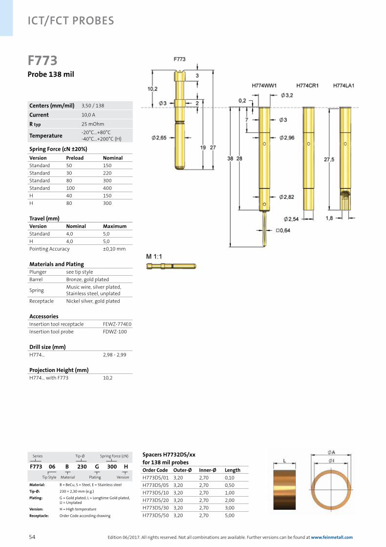
54
ICT/FCT Probes
Edition 06/2017. All rights reserved. Not all combinations are available. Further versions can be found at www.feinmetall.com
F773Probe 138 mil
Series Tip-Ø
Spring Force (cN)
F773 06 B 230 G 300 H
Tip Style
Material Plating
Version
Material: B = BeCu, S = Steel, E = Stainless steel
Tip-Ø: 230 = 2,30 mm (e.g.)
Plating: G = Gold plated, L = Longtime Gold plated, U = Unplated
Version: H = High temperature
Receptacle: Order Code according drawing
Spring Force (cN ±20%)Version Preload NominalStandard 50 150Standard 30 220Standard 80 300Standard 100 400H 40 150H 80 300
Travel (mm)Version Nominal MaximumStandard 4,0 5,0H 4,0 5,0Pointing Accuracy ±0,10 mm
Materials and PlatingPlunger see tip styleBarrel Bronze, gold plated
Spring Music wire, silver plated, Stainless steel, unplated
Receptacle Nickel silver, gold plated
AccessoriesInsertion tool receptacle FEWZ-774E0Insertion tool probe FDWZ-100
Drill size (mm)H774... 2,98 - 2,99
Projection Height (mm)H774... with F773 10,2
Spacers H7732DS/xx for 138 mil probesOrder Code Outer-Ø Inner-Ø LengthH773DS/01 3,20 2,70 0,10H773DS/05 3,20 2,70 0,50H773DS/10 3,20 2,70 1,00H773DS/20 3,20 2,70 2,00H773DS/30 3,20 2,70 3,00H773DS/50 3,20 2,70 5,00
Centers (mm/mil) 3,50 / 138
Current 10,0 A
R typ 25 mOhm
Temperature -20°C...+80°C-40°C...+200°C (H)

55
ICT/FCT Probes
Edition 06/2017. All rights reserved. Not all combinations are available. Further versions can be found at www.feinmetall.com
Tip Style Number Material Plating ∅ in mm Version
05 B G 2,30 -
06 B G 2,30 -
06 B G 2,30 H
06 B G 3,00 -
06 B G 3,00 H
06 B G 4,00 -
06 B G 4,00 H
07 S L 2,30 -
07 S L 4,00 -
09 S L 2,30 -
11 B G 1,80 -
12 B G 2,30 -
12 B G 3,00 -
12 B G 3,00 H
12 E U 2,30 -
14 S L 2,30 -
15 B G 2,30 -
15 B G 3,00 -
16 B G 1,40 -
16 B G 1,80 -
17 B G 2,30 -
17 B G 3,00 -
17 B G 3,00 H
18 B G 1,80 -
18 B G 1,80 H
21 S L 1,80 -
28 B G 2,30 -
28 B G 2,30 H
F773Probe 138 mil
Centers (mm/mil) 3,50 / 138
Current 10,0 A
R typ 25 mOhm
Temperature -20°C...+80°C-40°C...+200°C (H)
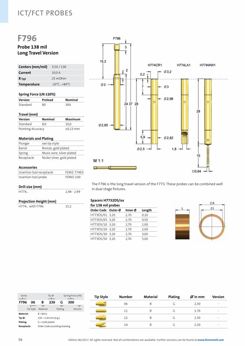
56
ICT/FCT Probes
Edition 06/2017. All rights reserved. Not all combinations are available. Further versions can be found at www.feinmetall.com
F796Probe 138 milLong Travel Version
Series Tip-Ø
Spring Force (cN)
F796 06 B 230 G 300
Tip Style
Material Plating
Version
Material: B = BeCu
Tip-Ø: 230 = 2,30 mm (e.g.)
Plating: G = Gold plated
Receptacle: Order Code according drawing
Spring Force (cN ±20%)Version Preload NominalStandard 80 300
Travel (mm)Version Nominal MaximumStandard 8,0 10,0Pointing Accuracy ±0,13 mm
Materials and PlatingPlunger see tip styleBarrel Bronze, gold platedSpring Music wire, silver platedReceptacle Nickel silver, gold plated
AccessoriesInsertion tool receptacle FEWZ-774E0Insertion tool probe FDWZ-100
Drill size (mm)H774... 2,98 - 2,99
Projection Height (mm)H774... with F796 15,2
Spacers H7732DS/xx for 138 mil probesOrder Code Outer-Ø Inner-Ø LengthH773DS/01 3,20 2,70 0,10H773DS/05 3,20 2,70 0,50H773DS/10 3,20 2,70 1,00H773DS/20 3,20 2,70 2,00H773DS/30 3,20 2,70 3,00H773DS/50 3,20 2,70 5,00
The F796 is the long travel version of the F773. These probes can be combined well in dual stage fixtures.
Tip Style Number Material Plating ∅ in mm Version
06 B G 2,30 -
11 B G 1,76 -
12 B G 2,30 -
14 B G 2,30 -
Centers (mm/mil) 3,50 / 138
Current 10,0 A
R typ 25 mOhm
Temperature -20°C...+80°C

57
ICT/FCT Probes
Edition 06/2017. All rights reserved. Not all combinations are available. Further versions can be found at www.feinmetall.com
Tip Style Number Material Plating ∅ in mm Version
01 S L 2,00 -
06 B G 1,20 L
06 B G 2,30 -
06 B G 2,50 L
06 B G 3,50 L
14 S L 2,30 -
14 S L 2,30 L
F785Probe 138 milLong Travel Version
Series Tip-Ø
Spring Force (cN)
F785 06 B 250 G 300 L
Tip Style
Material Plating
Version
Material: B = BeCu, S = Steel
Tip-Ø: 250 = 2,50 mm (e.g.)
Plating: G = Gold plated, L = Longtime Gold plated
Version: L = Long version
Receptacle: Order Code according drawing
Spring Force (cN ±20%)Version Preload NominalStandard 80 150Standard 80 300L 80 150L 80 300
Travel (mm)Version Nominal MaximumStandard 6,4 8,0L 6,4 8,0Pointing Accuracy ±0,10 mm
Materials and PlatingPlunger see tip styleBarrel Bronze, gold platedSpring Music wire, silver platedReceptacle Nickel silver, gold plated
AccessoriesInsertion tool receptacle FEWZ-774E0Insertion tool probe FDWZ-100
Drill size (mm)H774... 2,98 - 2,99
Projection Height (mm)H774... with F785 16,2H774... with F785...L 22,2
Spacers H7732DS/xx for 138 mil probesOrder Code Outer-Ø Inner-Ø LengthH773DS/01 3,20 2,70 0,10H773DS/05 3,20 2,70 0,50H773DS/10 3,20 2,70 1,00H773DS/20 3,20 2,70 2,00H773DS/30 3,20 2,70 3,00H773DS/50 3,20 2,70 5,00
The F785 is the long travel version of the F773. These probes can be combined well in dual stage fixtures.
Centers (mm/mil) 3,50 / 138
Current 10,0 A
R typ 25 mOhm
Temperature -20°C...+80°C
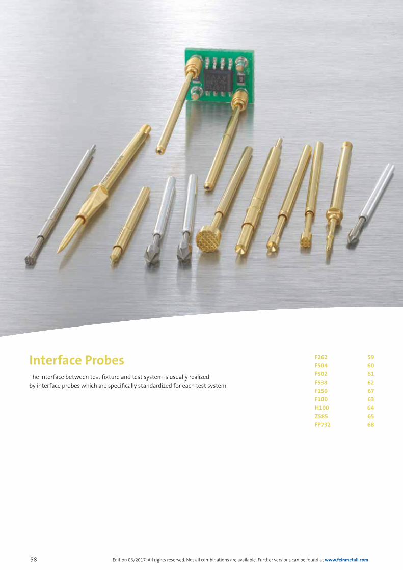
58 Edition 06/2017. All rights reserved. Not all combinations are available. Further versions can be found at www.feinmetall.com
The interface between test fixture and test system is usually realized by interface probes which are specifically standardized for each test system.
Interface Probes F262 59F504 60F502 61F538 62F150 67F100 63H100 64Z585 65 FP732 68

59Edition 06/2017. All rights reserved. Not all combinations are available. Further versions can be found at www.feinmetall.com
Tip Style Number Material Plating ∅ in mm Version
07 S L 1,00 -
F262For ATG Test Systems
Series Tip-Ø
Spring Force (cN)
F262 07 S 100 L 140
Tip Style
Material Plating
Version
Material: S = Steel
Tip-Ø: 100 = 1,00 mm (e.g.)
Plating: L = Longtime Gold plated
Spring Force (cN ±20%)Version Preload NominalStandard 0 40Standard 0 140
Travel (mm)Version Nominal MaximumStandard 5,0 7,0Pointing Accuracy ±0,08 mm
Materials and PlatingPlunger see tip styleBarrel Nickel silver, gold platedSpring Music wire, silver plated
Drill size (mm)Press ring as stop 1,08 - 1,10Press ring inserted 1,20 - 1,27
Projection Height (mm)F262... 12,0
Probe F262 is mainly used at the basic grid field of bare board testers.
Centers (mm/mil) 1,50 / 59
Current 2,0 A
R typ 100 mOhm
Temperature -20°C...+80°C
interfaCe proBes
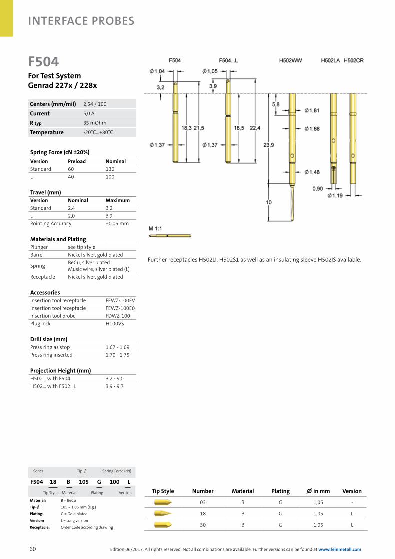
60
Interface Probes
Edition 06/2017. All rights reserved. Not all combinations are available. Further versions can be found at www.feinmetall.com
F504For Test SystemGenrad 227x / 228x
Series Tip-Ø
Spring Force (cN)
F504 18 B 105 G 100 L
Tip Style
Material Plating
Version
Material: B = BeCu
Tip-Ø: 105 = 1,05 mm (e.g.)
Plating: G = Gold plated
Version: L = Long version
Receptacle: Order Code according drawing
Spring Force (cN ±20%)Version Preload NominalStandard 60 130L 40 100
Travel (mm)Version Nominal MaximumStandard 2,4 3,2L 2,0 3,9Pointing Accuracy ±0,05 mm
Materials and PlatingPlunger see tip styleBarrel Nickel silver, gold plated
Spring BeCu, silver platedMusic wire, silver plated (L)
Receptacle Nickel silver, gold plated
AccessoriesInsertion tool receptacle FEWZ-100EVInsertion tool receptacle FEWZ-100E0Insertion tool probe FDWZ-100Plug lock H100VS
Drill size (mm)Press ring as stop 1,67 - 1,69Press ring inserted 1,70 - 1,75
Projection Height (mm)H502... with F504 3,2 - 9,0H502... with F502...L 3,9 - 9,7
Further receptacles H502LI, H502S1 as well as an insulating sleeve H502IS available.
Tip Style Number Material Plating ∅ in mm Version
03 B G 1,05 -
18 B G 1,05 L
30 B G 1,05 L
Centers (mm/mil) 2,54 / 100
Current 5,0 A
R typ 35 mOhm
Temperature -20°C...+80°C

61Edition 06/2017. All rights reserved. Not all combinations are available. Further versions can be found at www.feinmetall.com
interfaCe proBes
F502For Testsystem Luther & Maelzer
Series Tip-Ø
Spring Force (cN)
F502 03 S 076 N 130
Tip Style
Material Plating
Version
Material: S = Steel
Tip-Ø: 076 = 0,76 mm (e.g.)
Plating: N = Nickel plated
Receptacle: Order Code according drawing
Spring Force (cN ±20%)Version Preload NominalStandard 60 130
Travel (mm)Version Nominal MaximumStandard 2,7 4,1Pointing Accuracy ±0,05 mm
Materials and PlatingPlunger see tip styleBarrel Bronze, silver platedSpring Music wire, silver platedReceptacle Nickel silver, gold plated
AccessoriesInsertion tool receptacle FEWZ-100EVInsertion tool receptacle FEWZ-100E0Insertion tool probe FDWZ-100Plug lock H100VS
Drill size (mm)Press ring as stop 1,67 - 1,69Press ring inserted 1,70 - 1,75
Projection Height (mm)H502... with F502 6,2 - 12,0
Tip Style Number Material Plating ∅ in mm Version
03 S N 0,76 -
12 S N 1,90 -
Further receptacles H502LI, H502S1 as well as an insulating sleeve H502IS available.
Probe F502 is used in wired fixtures (LP1800 from atg Luther & Maelzer GmbH), and as interface probes in universal test systems. Probe F50241B160N170 used in universal test systems contacts the balls of the ALS-probes with a 6-point crown.
Centers (mm/mil) 2,54 / 100
Current 5,0 A
R typ 55 mOhm
Temperature -20°C...+80°C

62
Interface Probes
Edition 06/2017. All rights reserved. Not all combinations are available. Further versions can be found at www.feinmetall.com
F538For Test System Digitaltest MTS 300, L&M LP1800
Series Tip-Ø
Spring Force (cN)
F538 07 S 130 N 220
Tip Style
Material Plating
Version
Material: S = Steel
Tip-Ø: 130 = 1,30 mm (e.g.)
Plating: N = Nickel plated
Receptacle: Order Code according drawing
Tip Style Number Material Plating ∅ in mm Version
07 S N 1,30 -
07 S N 1,90 -
Further receptacles H502LI, H502S1 as well as an insulating sleeve H502IS available.
Probe F538 is used in wired fixtures (LP1800 from atg Luther & Maelzer GmbH) and as interface probes in universal test systems for testing vias and other applications in the field of bare board test.
Spring Force (cN ±20%)Version Preload NominalStandard 60 220
Travel (mm)Version Nominal MaximumStandard 2,7 4,0Pointing Accuracy ±0,05 mm
Materials and PlatingPlunger see tip styleBarrel Bronze, silver platedSpring Music wire, silver platedReceptacle Nickel silver, gold plated
AccessoriesInsertion tool receptacle FEWZ-100EVInsertion tool receptacle FEWZ-100E0Insertion tool probe FDWZ-100Plug lock H100VS
Drill size (mm)Press ring as stop 1,67 - 1,69Press ring inserted 1,70 - 1,75
Projection Height (mm)H502... with F538 7,2 - 13,0
Centers (mm/mil) 2,54 / 100
Current 5,0 A
R typ 55 mOhm
Temperature -20°C...+80°C
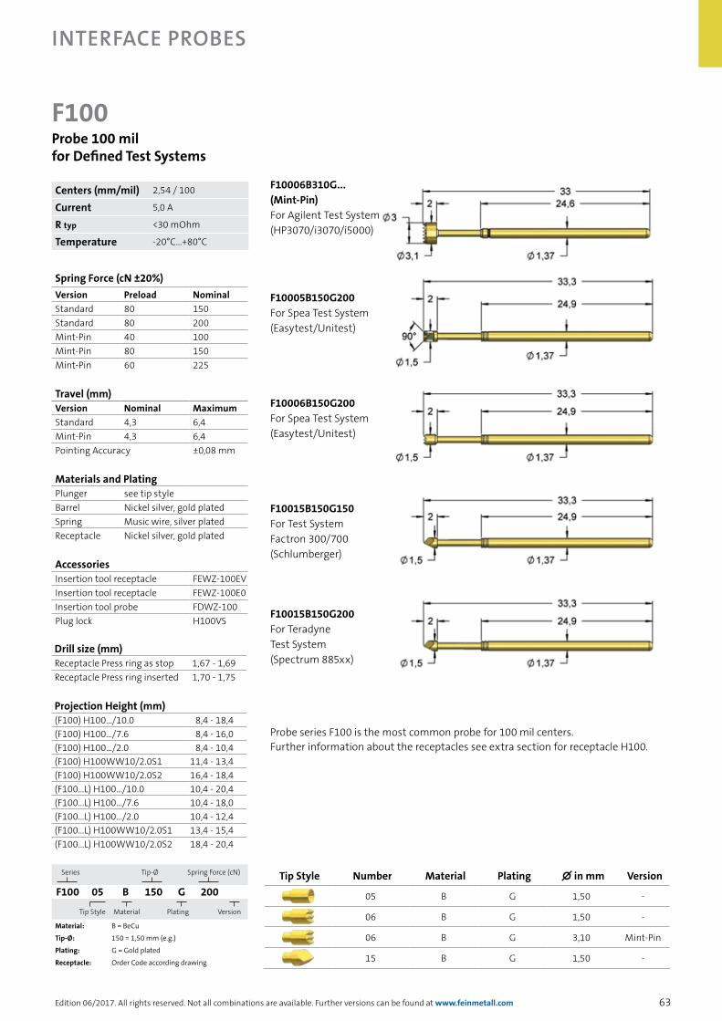
63
Interface Probes
Edition 06/2017. All rights reserved. Not all combinations are available. Further versions can be found at www.feinmetall.com
F100Probe 100 milfor Defined Test Systems
Series Tip-Ø
Spring Force (cN)
F100 05 B 150 G 200
Tip Style
Material Plating
Version
Material: B = BeCu
Tip-Ø: 150 = 1,50 mm (e.g.)
Plating: G = Gold plated
Receptacle: Order Code according drawing
Probe series F100 is the most common probe for 100 mil centers. Further information about the receptacles see extra section for receptacle H100.
Spring Force (cN ±20%)Version Preload NominalStandard 80 150Standard 80 200Mint-Pin 40 100Mint-Pin 80 150Mint-Pin 60 225
Travel (mm)Version Nominal MaximumStandard 4,3 6,4Mint-Pin 4,3 6,4Pointing Accuracy ±0,08 mm
Materials and PlatingPlunger see tip styleBarrel Nickel silver, gold platedSpring Music wire, silver platedReceptacle Nickel silver, gold plated
AccessoriesInsertion tool receptacle FEWZ-100EVInsertion tool receptacle FEWZ-100E0Insertion tool probe FDWZ-100Plug lock H100VS
Tip Style Number Material Plating ∅ in mm Version
05 B G 1,50 -
06 B G 1,50 -
06 B G 3,10 Mint-Pin
15 B G 1,50 -
F10006B310G...(Mint-Pin) For Agilent Test System (HP3070/i3070/i5000)
F10005B150G200 For Spea Test System (Easytest/Unitest)
F10006B150G200 For Spea Test System (Easytest/Unitest)
F10015B150G150 For Test System Factron 300/700 (Schlumberger)
F10015B150G200 For Teradyne Test System (Spectrum 885xx)
Drill size (mm)Receptacle Press ring as stop 1,67 - 1,69Receptacle Press ring inserted 1,70 - 1,75
Projection Height (mm)(F100) H100.../10.0 8,4 - 18,4(F100) H100.../7.6 8,4 - 16,0(F100) H100.../2.0 8,4 - 10,4(F100) H100WW10/2.0S1 11,4 - 13,4(F100) H100WW10/2.0S2 16,4 - 18,4(F100...L) H100.../10.0 10,4 - 20,4(F100...L) H100.../7.6 10,4 - 18,0(F100...L) H100.../2.0 10,4 - 12,4(F100...L) H100WW10/2.0S1 13,4 - 15,4(F100...L) H100WW10/2.0S2 18,4 - 20,4
Centers (mm/mil) 2,54 / 100
Current 5,0 A
R typ <30 mOhm
Temperature -20°C...+80°C

64
Interface Probes
Edition 06/2017. All rights reserved. Not all combinations are available. Further versions can be found at www.feinmetall.com
Series Length of Wire Wrap Pin
H 100 WW 10 / 7.6
Connection Type
Press Ring Position
Connection Type: CR= Crimp connectionLA = Solder connectionWW = Wire Wrap connectionLI = Stranded wireWL = Spring loaded connection
Length of Wire Wrap Pin: e.g. 10 = 10,0 mm
Press Ring Position: e.g. 7.6 = 7,6 mm
H100Receptacle 100 mil
Materials and PlatingReceptacle Nickel silver, gold plated
AccessoriesInsertion tool, variablefor Receptacle FEWZ-100EV
Insertion tool, fix for Receptacle FEWZ-100E0
Insertion tool, variablefor Receptacle FEWZ-100Exx
Drill size (mm)Receptacle Press ring as stop 1,67 - 1,69Receptacle Press ring inserted 1,70 - 1,75
Projection Height (mm)(F100) H100.../10.0 8,4 - 18,4(F100) H100.../7.6 8,4 - 16,0(F100) H100.../2.0 8,4 - 10,4(F100) H100WW10/2.0S1 11,4 - 13,4(F100) H100WW10/2.0S2 16,4 - 18,4(F100...L) H100.../10.0 10,4 - 20,4(F100...L) H100.../7.6 10,4 - 18,0(F100...L) H100.../2.0 10,4 - 12,4(F100...L) H100WW10/2.0S1 13,4 - 15,4(F100...L) H100WW10/2.0S2 18,4 - 20,4
For probes F100, F588 and F585 different receptacles are available with different connection types (e.g. LA, CR, WW), different press ring positions (e.g. 2,0; 7,6; 10,0 mm) and different wire-wrap posts (10,0; 19,0 mm length).
Plug locks H100VS can be used to close empty receptacles in order to prevent false assemblies and to avoid contamination.
Die insulating sleeve H502IS can be also used for receptacle H100.

65
Interface Probes
Edition 06/2017. All rights reserved. Not all combinations are available. Further versions can be found at www.feinmetall.com
Z585For Testing von ICs on PCBs (Test Jet)
Spring Force (cN ±20%)Version Preload NominalStandard 50 100S1 50 100
Travel (mm)Version Nominal MaximumStandard 5,0 9,6S1 5,0 9,6
Materials and PlatingPlunger BeCu, gold platedBarrel Nickel silver, gold platedSpring Music wire, silver platedReceptacle Nickel silver, gold plated
AccessoriesInsertion tool receptacle FEWZ-774E0Insertion tool probe FDWZ-100
Drill size (mm)H774... 2,98 - 2,99
Projection Height (mm)H774... with F796 15,2
DUT with IC Chip
Amplifier board
Sensor plate
Z58550B175G100S1 Z58550B175G100
The flexible contact head with spring element ensures an optimal adjustment of the sensor plate on the IC or component.
Order Code DescriptionZ58550B175G100S1 Test jet spring contact probe wit spiral spring head (Agilent)Z58550B175G100 Test jet spring contact probe with spiral spring head (Digitaltest)
Centers (mm/mil) 9,50 / 374
Current 3,0 A
R typ 30 mOhm
Temperature -20°C...+80°C
The Z585/Z588 is a special probe for non-contact gauging of IC-components. The contact probes are used in pairs as flexible holder for the sensor plate. This measuring principle is known as „TestJet“ in the Agilent test system and as “Frame Scan“ in the Teradyne test system. Mounting receptacles see H100.

66
Interface Probes
Edition 06/2017. All rights reserved. Not all combinations are available. Further versions can be found at www.feinmetall.com
Capacitive Sensors and AccessoriesTest system Description Order code Unit of trading
System Agilent („Testjet“ und „VTEP“)Testjet Signal Conditioner Board* (Mux Board) 2100175 1
Signal Conditioner Board* (Mux+REF B-Revision) 2100191 1Testjet Amplifier incl. 2 probes 2100830 bulk 2100176 1Testjet Amplifier incl. 2 probes Z58550B175G130S1 bulk 2101350 1Testjet Amplifier without probes 2102310 1Sensor Plates 9,5x12 mm (0,375x0,475 inch), usable area 5,5x10,3 mm (0,217x0,405 inch) SO14 2100823 10
Sensor Plates 10,8x14,6 mm (0,475x0,575 inch) SO20 2100824 10Sensor Plates 30x30 mm (1,2x1,2 inch) 2100825 1Sensor Plates 64x64 mm (2,5x2,5 inch) 2100826 1Sensor Plates 12,5x158 mm (0,5x6,1 inch) 2100827 1Sensor Plates* 30x30 mm (1,2x1,2 inch) 2100179 1Sensor Plates* 64x64 mm (2,5x2,5 inch) 2100180 1Sensor Plates* 12,5x158 mm (0,5x6,1 inch) 2100190 1Small Testjet Amplifier* incl. 2 probes 2100822 bulk 2100192 1Small Sensor Plates* B-C Size 4x6,4 mm also for VTEP 2100193 10Small Sensor Plates* D Size 5x7,6 mm also for VTEP 2100194 10Set: Small Testjet Amplifier* incl. 2 probes 2100822 soldered and Sensor Plate B-C-Size soldered 40400146 1
Set: Small Testjet Amplifier* incl. 2 probes 2100822 soldered and Sensor Plate D-Size soldered 40400147 1
Set: Small Testjet Amplifier* incl. 2 probes 2100822 soldered without Sensor Plate 40400104 1
VTEP VTEP Signal Conditioner Board* ( Mux-Board) 2101126 1VTEP Signal Conditioner Board* ( Mux+REF) 2101127 1VTEP Testjet Amplifier* incl. 2 probes 2100830 bulk 2101128 1VTEP Testjet Amplifier* incl. 2 probes Z58550B175G130S1 bulk 2102041 1
VTEP Testjet Amplifier* without probes 2102275 1VTEP Sensor Plates* 30x30 mm (1,2x1,2 inch) 2101131 1VTEP Sensor Plates* 64x64 mm (2,5x2,5 inch) 2101132 1VTEP Sensor Plates* 12,5x158 mm (0,5x6,1 inch) 2101130 1VTEP Small Testjet Amplifier* incl. 2 probes 2100822 bulk 2101133 1VTEP Small Sensor Plates, see above* orig. Agilent
System Teradyne („Framescan“ und „Capscan“)Teradyne Mux-Board 4-805960 1
Framescan
Teradyne Framescan Amplifier (higher amplification factor than System Agilent Testjet Amplifier) - alternatively also System Agilent Testjet Amplifier (not for VTEP)- Sensor Plates identical to System Agilent
2101970 1
Capscan identical to System Agilent Small Testjet parts (not for VTEP, see above)
System Digitaltest („Opens Check“)Digitaltest Opens Check Board (Amplifier) 2100199Passive Sensor Connection Board incl. 2 probes Z58550B175G130 4-806448
Sensor Plates identical System Agilent, see aboveOpens Check probe with FM spiral head Z58550B175G130 Z58550B175G130 10Plug-in part for FM spiral spring probe SO585B02G SO585B02G 10
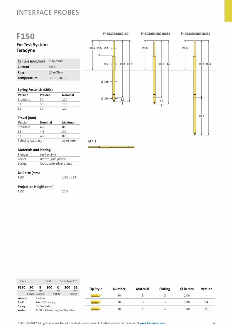
67
Interface Probes
Edition 06/2017. All rights reserved. Not all combinations are available. Further versions can be found at www.feinmetall.com
F150For Test System Teradyne
Series Tip-Ø
Spring Force (cN)
F150 30 B 100 G 100 S1
Tip Style
Material Plating
Version
Material: B = BeCu
Tip-Ø: 100 = 1,00 mm (e.g.)
Plating: G = Gold plated
Version: S1 /S2 = different Length of Contact end
Spring Force (cN ±20%)Version Preload NominalStandard 50 100S1 50 100S2 50 100
Travel (mm)Version Nominal MaximumStandard 4,5 8,0S1 4,5 8,0S2 4,5 8,0Pointing Accuracy ±0,08 mm
Materials and PlatingPlunger see tip styleBarrel Bronze, gold platedSpring Music wire, silver plated
Drill size (mm)F150 1,62 - 1,65
Projection Height (mm)F150 20,5
Tip Style Number Material Plating ∅ in mm Version
30 B G 1,00 -
30 B G 1,00 S1
30 B G 1,00 S2
Centers (mm/mil) 2,54 / 100
Current 5,0 A
R typ 20 mOhm
Temperature -20°C...+80°C

68
Interface Probes
Edition 06/2017. All rights reserved. Not all combinations are available. Further versions can be found at www.feinmetall.com
Tip Style Number Material Plating ∅ in mm Version
18 S L 1,00 E19
FP732Threaded Probe 100 mil, Long Travel Flying Probe for Skorpion Tester
Spring Force (cN ±20%)Version Preload NominalStandard 50 150
Travel (mm)Version Nominal MaximumStandard 6,4 8,0Thread (M) 1,6Wrench Size 2,0Pointing Accuracy ±0,10 mm
Materials and PlatingPlunger see tip styleBarrel Brass, gold platedSpring Music wire, gold platedReceptacle Brass, gold plated
Series Tip-Ø
Spring Force (cN)
FP732 18 S 100 L 150 E19
Tip Style
Material Plating
Version
Material: S = SteelTip-Ø: 100 = 1,00 mm (e.g.)
Plating: L = Longtime Gold platedReceptacle: Order Code according drawing
Drill size (mm)H732LARD 2,00 - 2,02
Projection Height (mm)H732LARD 19,8H732LARD/5 24,6
AccessoriesInsertion tool receptacle FEWZ-772E0Screw-in tool probe FWZVF3S2 (T2)
Centers (mm/mil) 3,00 / 118
Current 5,0 A
R typ 20 mOhm
Temperature -20°C...+80°C

69Edition 06/2017. All rights reserved. Not all combinations are available. Further versions can be found at www.feinmetall.com
Contact Probes for Special ApplicationsIn addition to contact probes for testing PCBs a wide range of further contact probes for other special applications are available. These include for example:→ Contact probes for presence and position test→ High current probes→ Kelvin probes for 4-wire measurements→ Radio frequency probes

70
Probes for sPecial aPPlications
Edition 06/2017. All rights reserved. Not all combinations are available. Further versions can be found at www.feinmetall.com
Switch ProbesAs Opener and Closer
Travel [mm]
1
00 51,7
Switc
h st
atus
Switch Characteristic
Travel [mm]
1
00 51,7
Switc
h st
atus
Switch Characteristic
Presence Test with Switch ProbesSwitch probes are contact elements, which open or close an electric circuit after a defined switch travel. This condition persists beyond the switching point.
Typical applications:
→ Presence test of components or connectors
→ Voltage-free detection with synthetic heads
→ Short-circuit-proof modules by electrically isolated switch elements (voltage-free system)
→ Installation of intrinsically save circuits (only with NC-versions)
Versions of switch probes:
→ Openers (NC - normally closed), closers (NO - normally open)
→ Different switch travels
→ Probe for a gentle lateral contacting by ball element
→ Short and long versions to realize different projection heights
→ Long travel versions for depth determination
Switch Probe (NO) Switch Probe (NC)
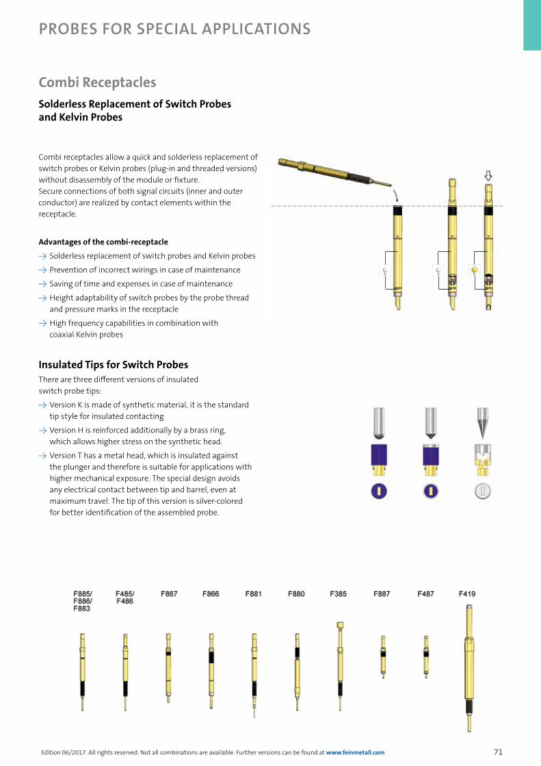
71
Probes for sPecial aPPlications
Edition 06/2017. All rights reserved. Not all combinations are available. Further versions can be found at www.feinmetall.com
Combi receptacles allow a quick and solderless replacement of switch probes or Kelvin probes (plug-in and threaded versions) without disassembly of the module or fixture. Secure connections of both signal circuits (inner and outer conductor) are realized by contact elements within the receptacle.
Advantages of the combi-receptacle
→ Solderless replacement of switch probes and Kelvin probes
→ Prevention of incorrect wirings in case of maintenance
→ Saving of time and expenses in case of maintenance
→ Height adaptability of switch probes by the probe thread and pressure marks in the receptacle
→ High frequency capabilities in combination with coaxial Kelvin probes
Insulated Tips for Switch ProbesThere are three different versions of insulated switch probe tips:
→ Version K is made of synthetic material, it is the standard tip style for insulated contacting
→ Version H is reinforced additionally by a brass ring, which allows higher stress on the synthetic head.
→ Version T has a metal head, which is insulated against the plunger and therefore is suitable for applications with higher mechanical exposure. The special design avoids any electrical contact between tip and barrel, even at maximum travel. The tip of this version is silver-colored for better identification of the assembled probe.
Combi ReceptaclesSolderless Replacement of Switch Probes and Kelvin Probes

72
Probes for sPecial aPPlications
Edition 06/2017. All rights reserved. Not all combinations are available. Further versions can be found at www.feinmetall.com
Switch Probe with Ball Head for Lateral ContactingThis series allows contacting applications with laterally moved DUT.
Function:
A rolling ball as contact element is insensitive against lateral forces, which leads to a remarkably higher durability compared to contact probes with fix plunger head of similar shape. This probe does not leave any scratching or damaging of the DUT.
Typical applications:
Lateral presence test of components or connectors, drill holes, screws etc.
Travel [mm]
1
00 51,7
Switc
h st
atus
Switch Characteristic
F88890S0003U100S08F88890S1102U100S07F88890S1103U200S05F88890S1101U200S05F88890M2104G150
With thread, without switch
With thread, with switch
With thread, with switch
With thread, with switch
Without thread, with switch

73
Probes for sPecial aPPlications
Edition 06/2017. All rights reserved. Not all combinations are available. Further versions can be found at www.feinmetall.com
Switch Probes with Off-on-off Function The off-on-off function allows an exact position test with only one switch probe.
Function:
Whereas standard switch probes only have one switch point, the new switch probes with off-on-off function have two switch points. After a defined travel the switch circuit is closed and after a further travel (e.g. 1,0 mm) the switch circuit is opened again. The measured position can be determined very precisely, the accuracy of the switch points is ± 0,2 mm.
Typical applications:
Length detection of connector pins or determination of correct hole depths.
Travel [mm]
1
00 51,7
Switc
h st
atus
Switch Characteristic
F899F899PF485F487 F486
Without thread, with pneumatic connection
With thread and pneumatic connection
With threadWith threadWith thread
OFF
OFFON
Additionally to the pure mechanical versions also a pneumatically controlled version is available for selective or lateral contacting requirements..

74
Probes for sPecial aPPlications
Edition 06/2017. All rights reserved. Not all combinations are available. Further versions can be found at www.feinmetall.com
The position sensor system has been developed to enable an exact measure-ment of the travel of the plunger additionally to contacting the test item.
The system has a modular design and consists of a contact probe, a receptacle and a sensor element with integrated potentiometer. The potentiometer is galvanically isolated from the probe.
After applying an operating voltage, the sensor supplies a measurement voltage that is linear to the travel of the plunger (potentiometric operation). Alternatively, with restrictions regarding accuracy and life cycle, also the resulting resistance can be used as measurement value (resistive operation). FEINMETALL recommends the potentiometric operation for all position sensor systems. The measurement results can be analyzed by the available tester environment, commonly.
VariantsThe position sensor system is available for different centers of 75 mil, 100 mil and 157 mil. For 100 mil centers a twist proof version is available (PS756). The system for 157 mil is suitable for airtight modules or fixtures (i.e. leakage rate < 0,5 cm³ / min at 0,7 bar).
Measuring rangesPS175: 0…6,4 mm (75 mil) PS756: 0...4,4 mm (100 mil) PS732: 0…5,0 mm (100 mil) PS733: 0…5,0 mm (157 mil)
U0 Operating voltage (maximum 10 VDC)Um Measuring voltage (potentiometric op.) (U1 < Um < UP – U3)Rm Measuring resistance (resistive op.) (R1 < Rm < RP – R3)R1 Initial resistance U1 Initial voltage (U1= I * R1)R3 Final resistanceU3 Final voltage (U3= I * R3)RP Potentiometric resistance (4,5 kOhm ± 20%) (RP = R1 + R + R3)Rs Slider resistanceRL Load resistor (optional to protect against over-current at the slider)
Position Sensor System
CalibrationDue to test principle with a certain initial and final resistance and due to electrical and mechanical tolerances the exact plunger position in millimeter requires a calibration of the position sensor system after assembly.
Measurement of relative valuesBy calculating the difference between two measurement values of one probe deviations related to a required position can be determined in positive or negative travel direction.
Reference measurementBy calculating the difference between two measurement values of different probes deviations related to a reference position can be determined.
Contact Probe with Integrated Potentiometer Contact probe - Receptacle - Sensor element
PS73306B300G250 H733PSRD PS157F060R5.2
PS73206B200G090 H732PSRD PS100F060R5.2
PS17511B064G100 H175PSRD PS075F060R6.5
Modular Design of the Position Sensor System
157 mil
100 mil
75 mil
ConnectionsRed: Operating voltage U0Black: Measuring signal Um or RmWhite: MassBlue: Test point of contact probe tip (maximum current 1 A)
Specification sensor elementMeasuring principle: potentiometric Accuracy: ≤ 2% Reproducibility: typ. ≤ ±0,05 mm Therm. resist. coeff. 5x10⁻⁵/K Nominal spring force: 60 cN Preload: 40 cN Nominal: 4,0 mm
The reference can either be a certain reference point of the test item or a special “golden device”.
Zero balanceDepending on the hard- and software of the test system the measurement signal can be zeroed at user-defined positions. This method allows positive or negative deviations without calculating any differences.
FEINMETALL recommends periodic calibration and zeroing of the system.

75
Probes for sPecial aPPlications
Edition 06/2017. All rights reserved. Not all combinations are available. Further versions can be found at www.feinmetall.com
Different Solutions for Presence and Position Tests
Standard Switch ProbesSwitch probes open or close a switch circuit after a defined switch travel.
NO – „normally open“ = closer NC – „normally closed“ = opener
Off-on-off Switch Probes Switch probes with off-on-off function have two switch points. After a defined travel the switch circuit is closed and after a further travel (e.g. 1,0 mm) the switch circuit is opened again.
Off-on-off - 2 switch points
Position Sensor System The position sensor system has a sensor element with integrated potentiometer, that allows an exact measurement of the travel.
Travel measurement
Travel in mm
1
00 51,7
Switc
h st
atus
Switch Characteristic
Travel in mm
1
00 52,5 3,5
Switc
h st
atus
Switch Characteristic
Volta
ge
Travel in mm
1
00 5
Measurement
The pictures below show the different categories of FEINMETALL solutions with increasing accuracy. Simple solutions like using standard switch probes or step probes only allow a statement of OK or NOT OK. With the off-on-off switch probe with two switch points the result is more precise. With the position sensor system the exact position of a DUT can be measured and documented. The following pages include detailed information about corresponding probes and applications.
Standard Switch Probes
Fault not detected
OK OKNOK
OK too short too longSituation:
Result:
Off-on-off Switch Probes
OKNOK NOK
Position Sensor System
3 exact measuring results
too short too longOK too short too longOK

76
Probes for sPecial aPPlications
Edition 06/2017. All rights reserved. Not all combinations are available. Further versions can be found at www.feinmetall.com
Special head made of silver alloy In high current applications ideally no voltage should apply and accordingly no current should flow during closing or releasing the contact. Otherwise, an electric spark may occur, which may damage the surface of the contact area. To avoid or at least minimise such a contact-burn-off, FEINMETALL offers tips made of a special silver alloy to minimise the contact-burn-off, reducing the transition resistance and lead to a longer life time of the probes.
Contact burn-off
Basics of High Current ProbesFor high current applications the design of a spring contact probe has to consider a minimal electrical internal probe resistance as well as contact resistance. Otherwise, especially the spring of the probe would be overheated, what would lead to a remarkable reduction of the probe life time. A low electrical resistance of the probe significantly depends of the design and the material of the contact probe. Independently from the design of the probe a higher contact force cal also increase the maximum allowed current. The maximum continuous current is defined as IRMS (root-mean-square value). It is mainly limited by the maximum tolerable warming of the probe. The maximum current values in the specifications all refer to this IRMS.The design of springs of FEINMETALL high current probes ensures that also high temperatures up to 200°C do not lead to damages or a reduction in lifetime.
High current probes with continuous plungerhave the lowest resistance and therefore allow a high current loading. If the electrical connection is assembled at the end of the continuous plunger, the cable moves synchronously with the plunger. Those contact probes always have to be connected with flexible cables.
HIGH CURRENT PROBES
F310 F320 F330 F340 F772C F773C F775C F360C F723C F732C F733C F762C F735C F348C

77
Probes for sPecial aPPlications
Edition 06/2017. All rights reserved. Not all combinations are available. Further versions can be found at www.feinmetall.com
High current probe for contacting flat blade connectors Due to the twist proof design the plunger is always brought to the test item well aligned. Once the plunger is compressed by contacting the blade connector, it is twisted up to a maximum of 20°. This results in a good electrical contact without damaging or scratching the tested item.
High current probe with coaxial design For charging and discharging of accumulator cells and simultaneously measuring the voltage special coaxial high current probes have been developed.
High current probes with split plungersare designed that way, that under force effect the plunger elements optimally establish a low-resistance connection to the barrel of the contact probe. As a consequence, the current flows mainly through plunger and barrel without stressing the spring strongly.
HIGH CURRENT PROBES
High current blocks Due to the integrated spring loaded plungers, this block offers a low resistance contact even if the contact surface is uneven or inclined. The block is designed to be mounted directly into conductive material to make use of the whole block surface.
1860C007F349C 1860C0081860C0041860C0031860C005F840
1860C0091860C006
1860C001

78
Probes for sPecial aPPlications
Edition 06/2017. All rights reserved. Not all combinations are available. Further versions can be found at www.feinmetall.com
A Kelvin probe is a coaxial contact probe with two electrically insulated measuring circuits. The typical 4-wire measurement is based on a constant current, flowing through the test resistance and the measurement of the resulting drop in voltage, which is directly proportional to the resistance value. According “I=constant” and because of the very high internal resistance of the voltmeter, the cable and contact resistances are not influencing the measuring result.
This leads to high accuracy of this measuring method. The contacting for current source and voltmeter is realized by two Kelvin probes, ideally located very close to the device under test.
The constant current usually is carried by the outer conductor (force signal), while the voltage drop is detected by the inner conductor (sense signal). The inner and outer conductors of FEINMETALL coaxial probes are independently spring loaded in order to balance mechanical tolerances and heights.
1860C007F349F832 F840F822F835F810F805 1860C0081860C004
for Kelvin Measurement(4-Wire Measurement)
Coaxial Probes

79
Probes for sPecial aPPlications
Edition 06/2017. All rights reserved. Not all combinations are available. Further versions can be found at www.feinmetall.com
SMD mini coax and SMD switch connectorsare used on PCBs as RF interfaces. To contact these FEINMETALL provides different types of RF probes (e.g. HF66).
PCB Test Points For RF contacts directly on the PCB special RF probes are available. The probe design of these probes (e.g. HF05, HF60) is adapted to the typical require-ments of the test points.
ConnectorsIn various telecommunications, consumer electronics and automotive applications different standard connectors like SMA, SMB, SMC, HSD are used. FEINMETALL offers different probe series for contacting these connectors (e.g. HF60, HF19, HF66).
FEINMETALL offers sophisticated contact solutions for various industries and applications. Coaxial probes cover a wide range of radio frequency applications like contacting standard RF connectors, switch connectors or RF test points on the PCB.
e.g. HF60-0001 SMA-F 8 P MCX - Cutoff frequency Connection type
Series DUT Mounting version
Number
Center
Coaxial Probes
HF66 HF05HF19HF60
for Radio Frequency Tests and Transmission of Radio Frequency Signals

80
accessories for TesT fixTures
Edition 06/2017. All rights reserved. Not all combinations are available. Further versions can be found at www.feinmetall.com
F419 (NO)Switch Probe 256 milLong Travel, Threaded
Tip Style Number Material Plating Ø in mm Version
11 K U 3,00 -
Series Tip-Ø
Spring Force (cN)
F419 11 K 300 U 400
Tip Style
Material Plating
Version
Material: K = Synthetic Tip-Ø: 300 = 3,00 mm (e.g.)
Plating: U = UnplatedReceptacle: Order Code according drawing
Spring Force (cN ±20%)Version Preload NominalStandard 200 400
Travel (mm)Version Nominal MaximumStandard 11,0 16,0Switch travel (mm) 2,0Thread (M) 4,0x0,5Wrench Size 5,0Pointing Accuracy ±0,06 mm
Materials and PlatingPlunger see tip styleBarrel Brass, gold platedSpring Music wire, silver platedReceptacle Brass, gold plated
AccessoriesInsertion tool receptacle FEWZ-340E0Screw-in tool probe FWZ888 (T)
Drill size (mm)Receptacle with knurl 5,50 - 5,54
Projection Height (mm)H419KB 27,3
Switch travel2,0 mm
This probe is often used in test fixtures for detecting if a DUT is inserted. The switch function of the probe is activated when the lid of the fixture closes and pushes down the DUT (switch travel of 2,0 mm). The high maximum travel of 16 mm still allows to cover the whole fixture travel of further 10 to 14 mm.
Centers (mm/mil) 6,50 / 256
Current 10,0 A
Current (Switch) 1,0 A
R typ 20 mOhm
Temperature -20°C...+80°C
NEW
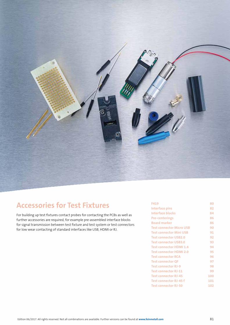
81
accessories for TesT fixTures
Edition 06/2017. All rights reserved. Not all combinations are available. Further versions can be found at www.feinmetall.com
For building up test fixtures contact probes for contacting the PCBs as well as further accessories are required, for example pre-assembled interface blocks for signal transmission between test fixture and test system or test connectors for low wear contacting of standard interfaces like USB, HDMI or RJ.
Accessories for Test Fixtures F419 80Interface pins 82Interface blocks 84Pre-centerings 86Board marker 86Test connector Micro USB 90Test connector Mini USB 91Test connector USB2.0 92Test connector USB3.0 93Test connector HDMI 1.4 94Test connector HDMI 2.0 95Test connector RCA 96Test connector QF 97Test connector RJ-9 98Test connector RJ-11 99Test connector RJ-45 100Test connector RJ-45 f 101Test connector RJ-50 102

82
accessories for TesT fixTures
Edition 06/2017. All rights reserved. Not all combinations are available. Further versions can be found at www.feinmetall.com
Interface PinsBrass, gold plated (rhodanized)
I-G1 10,0 Ampere
I-G1S1 10,0 Ampere
I-G1S2 10,0 Ampere
I-G1S3 10,0 Ampere
I-P18WR/0.8 10,0 Ampere
I-P1S4 10,0 Ampere
I-Z1 10,0 Ampere
I-Z1WR/0.8 10,0 Ampere
I-C22WW/2 10,0 Ampere
I-D22WW/2 10,0 Ampere
I-D23WW/3 10,0 Ampere
I-D32WW/12 10,0 Ampere

83
accessories for TesT fixTures
Edition 06/2017. All rights reserved. Not all combinations are available. Further versions can be found at www.feinmetall.com
I-P1 30,0 Ampere
I-P16LA/0.9 30,0 Ampere
I-P20LA/2.5 30,0 Ampere
I-P1S2 40,0 Ampere
I-Z1S2 15,0 Ampere
I-D19S1/2 15,0 Ampere
I-C17LA/2 20,0 Ampere
I-C18LA/3 20,0 Ampere
I-D17LA/2 20,0 Ampere
Interface PinsBrass, gold plated (rhodanized)

84
accessories for TesT fixTures
Edition 06/2017. All rights reserved. Not all combinations are available. Further versions can be found at www.feinmetall.com
Interface Blocks
* The sum of the currents lead to a heating of the blocks due to power loss. The maximum allowed rise of this temperature is limited to 80 Kelvin.
FEINMETALL interface blocks (Pylon blocks) are used as internal interface. The integrated spring contact probes guarantee a good signal transmission with low transfer resistances. This is only a selection of available signal blocks, further variants on request.
Signal Block 170 pole (max. 5A*)
Fixture sideOrder code: 43900002Receptacle: - Contact pin: I-Z1
Receiver side (Wire-Wrap connection)Order code: 43900032Receptacle: H502WW Contact probe: F50430B104G130L
Signal Block 170 pole (max. 5A*)
Fixture sideOrder code: 43900032-100Receptacle: H502WWContact pin: I-Z1S2
Receiver side (Wire-Wrap connection)Order code: 43900032Receptacle: H502WW Contact probe: F50430B104G130L
Signal Block 170 pole (max. 5A*)
Fixture sideOrder code: 43900015Receptacle: - Contact pin: I-G1
Receiver side (Wire-Wrap connection)Order code: 43900017Receptacle: H502WW Contact probe: F50403B104G130
Signal Block 170 pole (max. 5A*)
Fixture sideOrder code: 43900015Receptacle: - Contact pin: I-G1
Receiver side (Solder connection)Order code: 43900018Receptacle: H502LA Contact probe: F50403B104G130

85
accessories for TesT fixTures
Edition 06/2017. All rights reserved. Not all combinations are available. Further versions can be found at www.feinmetall.com
Interface Blocks
Fixture sideOrder code: 43900066Receptacle: -Contact pin: I-C22WW/2
Signal Block 85 pole (max. 5A*)
Receiver side (Wire-Wrap connection)Order code: 43900067Receptacle: H502WW Contact probe: F50403B104G130
Signal Block 85 pole (max. 5A*)
Fixture sideOrder code: 43900022Receptacle: -Contact pin: I-C17LA/2
Receiver side (Solder connection)Order code: 43900021Receptacle: H502LA Contact probe: F50403B104G130
Signal Block 85 pole (max. 5A*)
Fixture sideOrder code: 43900022-200Receptacle: H502LAContact pin: I-Z1S2
Receiver side (Solder connection)Order code: 43900021Receptacle: H502LA Contact probe: F50403B104G130
Signal Block 85 pole (max. 5A*)
Fixture sideOrder code: 43900064Receptacle: -Contact pin: I-D22WW/2
Receiver side (Wire-Wrap connection)Order code: 43900065Receptacle: H502WWContact probe: F50430B104G100L
Signal Block 145 pole (max. 5A*)
Fixture sideOrder code: 43900024Receptacle: H502LAContact pin: I-Z1S2
Receiver side (Solder connection)Order code: 43900023Receptacle: H502LA Contact probe: F50430B105G130L
High Current Block 20 pole (max. 24 A*)
Fixture sideOrder code: 43900027Receptacle: -Contact pin: I-P20LA/2.5
Receiver side (Solder connection)Order code: 43900028Receptacle: H735LA Contact probe: F73506B400G300C
Pneumatic Block 8 pole
Fixture sideOrder code: 43900026
Receiver sideOrder code: 43900025
High Current Block 32 pole (max. 20 A*)
Receiver side (Solder connection)Order code: 2101178
Fixture sideOrder code: 2101179

86
accessories for TesT fixTures
Edition 06/2017. All rights reserved. Not all combinations are available. Further versions can be found at www.feinmetall.com
Pre-centerings are used to simplify the insertion of the DUT. Depending on the height of the mounted components in the DUT, pre-centerings are available in different lengths. For DUTs with larger tolerances also eccentrically adjustable pre-centerings can be used.
Order code Description
4106028 Pre-centering aluminum, blue, anodized, eccentrically adjustable, 16 mm projection
4106031 Pre-centering aluminum, blue, anodized, 30 mm projection
4106010-001 Pre-centering aluminum, blue, anodized, 15 mm projection
4106010 Pre-centering plastic, black, 15 mm projection
4106023 Pre-centering plastic, black, 30 mm projection
Pre-centerings
Board markers are used for optical marking of good parts after being tested.
The tip of the board marker is set onto the board. After being tested, a current pulse initiates a twist movement of the board marker for scratching a permanent mark into the board.
For the board marker replacement tips and a synthetic mounting receptacle are available.
Order code Description
4-BMP-01 Board Marker
4-BMT-01 Board Marker replacement tip
4-BMP-01-H Board Marker mounting receptacle PVC black
Board Marker

87
accessories for TesT fixTures
Edition 06/2017. All rights reserved. Not all combinations are available. Further versions can be found at www.feinmetall.com
TEST CONNECTORS FOR USB, RJ AND HDMI
Durable Test Connectors for ICT and FCT Test
The need of contacting standard USB or RJ connections and interfaces is increasing in the field of in-circuit and functional test of PCBs, because the standardization of these interfaces has great advantages.
Compared to a normal USB or RJ45 plug, a specific test contact has the advantage that it does not lock into the socket. This leads to a low-wear contact with a long life time of more than 100 000 test cycles. Additionally unwanted stress or damage of the contact springs within the test item can be avoided. The connection between the test contact and the test fixture or module is realized in a very simple way without soldering just by using the standard plug of the respective interface (plug and play). For maintenance purposes the exchange of the test contact is therefore very simple.
The test contacts can be mounted into test fixtures or modules easily and effectively. The contacting of the DUT can be realized either by the vertical travel or the test fixture or by integrating the test contacts into a pneumatically controlled contacting unit.
With these new test contacts FEINMETALL extends the portfolio of contact probes for test engineering and offers even more comprehensive contacting solutions to its customers.
RJ-9
RJ-11
RJ-45
RJ-50
F-Type
RCA
Mikro-USB
Mini-USB
USB 2.0
USB 3.0
HDMI 1.4
HDMI 2.0

88
accessories for TesT fixTures
Edition 06/2017. All rights reserved. Not all combinations are available. Further versions can be found at www.feinmetall.com
Mounting of Test Connectors
Align the lower level of the test connector on the lower internal level of the connector to test (DUT)
Align the median level of the connector to be tested (DUT) and of the test connector.
Alignment of the levels
DUT Test connector
Test connectorAlignment of the levels
DUT
Choose the test connector and holding device according to your needs.In this example: USB Test connector
DUT
Holding device
Please note the following guidelines for building up a test fixture

89
accessories for TesT fixTures
Edition 06/2017. All rights reserved. Not all combinations are available. Further versions can be found at www.feinmetall.com
Mounting of Test Connectors
Threaded hole M3
Threaded hole M3
Opening for test connector
Opening for test connector
Distance 0,5 - 1,0 mm
Threaded pin
Opening
Carrier plate
Test connectorHolding device
Cylinder screw
Loosen the retaining screw of the test connector. Insert the test connector into the DUT until it comes to rest. Retract the test connector for 0.5 to 1 mm in order to prevent damages of the DUT. Now the test connector can be fixed by using the threaded pin.
Both, the cylinder screws and the threaded pin require a hex wrench SW2,5 mm.
Cut a sufficient opening into the carrier plate to have enough space for later insertion of the test connector from the back. Leave at least 1 mm space between opening and test connector.
Threaded hole M3
Threaded hole M3
Carrier plate
Place two opposite threaded holes M3 onto the carrier plate. For fixing of the holding device, two screws M3x8 (ISO4768) are required.

90
accessories for TesT fixTures
Edition 06/2017. All rights reserved. Not all combinations are available. Further versions can be found at www.feinmetall.com
TC-P 195 005 USB 2.0 B MicroTest Connector for Micro USB
Test connector for Micro USB (5 pole) for contacting Micro USB interfaces. Application in smaller USB devices like cameras, mobile phones, radios, hard disks etc.
Features:
→ Report on Micro USB type B
→ Smooth contact to test item (front view)
→ Simple connection to the test system with standard USB cable (rear view)
→ Up to 200.000 contact cycles
Front view Rear view
Max. Data rate 480 Mbit/s
Voltage 25 VAC / 60 VDC
Current 1,5 A at 25°C
R typ <30 mOhm
Temperature -20°C...+75°C
TC-H 195Holding Device forTest Connector Micro USB
Due to the centered seat of the test connector the holding device allows a parallel movement of the test connector and its connection.
→ Floating-mounting of test connectors of ± 0,4 mm in x- and y-direction
→ A torsion angle of up to 1.8 ° ± 0.2 ° is possible
→ The holding device has a life cycle of more than 500.000 mechanical movements
→ The holding device is fixed only by two screws at the upper and lower ends
→ The test connector is attached to the holding device using only one locking screw
Both, the cylinder screws and the threaded pin require a hex wrench SW2,5 mm.
Series
Pole count Type
e.g. TC-P 195 005 USB 2.0 B micro
Holding device Contact side
Version
NEW

91
accessories for TesT fixTures
Edition 06/2017. All rights reserved. Not all combinations are available. Further versions can be found at www.feinmetall.com
TC-P 198 005 USB 2.0 B MiniTest connector for Mini USB
Test connector for Mini USB (5 pole) for contacting Mini USB Interfaces. Application in smaller Mini-USB devices like cameras, mobile phones, radios, hard disks etc.
Features:
→ Report on Mini USB type B
→ Smooth contact to test item (front view)
→ Easy connection to test system with standard USB cable (rear view)
→ Up to 200.000 contact cycles
Max. Data rate 480 Mbit/s
Voltage 25 VAC / 60 VDC
Current 1,0 A at 25°C
R typ <50 mOhm
Temperature 0°C...+50°C
TC-H 198Holding Device for Test Connector mUSB / USB 2.0 / USB 3.0
Front view Rear view
NEW
Due to the centered seat of the test connector the holding device allows a parallel movement of the test connector and its connection.
→ Floating-mounting of test connectors of ± 0,4 mm in x- and y-direction
→ A torsion angle of up to 1.8 ° ± 0.2 ° is possible
→ The holding device has a life cycle of more than 500.000 mechanical movements
→ The holding device is fixed only by two screws at the upper and lower ends
→ The test connector is attached to the holding device using only one locking screw
Both, the cylinder screws and the threaded pin require a hex wrench SW2,5 mm.
Series
Pole count Type
e.g. TC-P 198 005 USB 2.0 mini
Holding device Contact side
Version
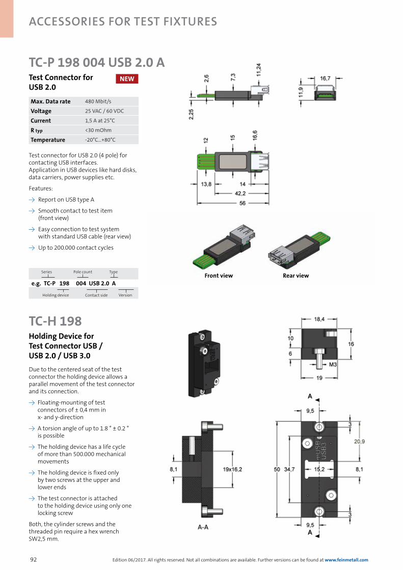
92
accessories for TesT fixTures
Edition 06/2017. All rights reserved. Not all combinations are available. Further versions can be found at www.feinmetall.com
TC-P 198 004 USB 2.0 ATest Connector for USB 2.0
Test connector for USB 2.0 (4 pole) for contacting USB interfaces. Application in USB devices like hard disks, data carriers, power supplies etc.
Features:
→ Report on USB type A
→ Smooth contact to test item (front view)
→ Easy connection to test system with standard USB cable (rear view)
→ Up to 200.000 contact cycles
Max. Data rate 480 Mbit/s
Voltage 25 VAC / 60 VDC
Current 1,5 A at 25°C
R typ <30 mOhm
Temperature -20°C...+80°C
Front view Rear view
TC-H 198Holding Device for Test Connector USB / USB 2.0 / USB 3.0Due to the centered seat of the test connector the holding device allows a parallel movement of the test connector and its connection.
→ Floating-mounting of test connectors of ± 0,4 mm in x- and y-direction
→ A torsion angle of up to 1.8 ° ± 0.2 ° is possible
→ The holding device has a life cycle of more than 500.000 mechanical movements
→ The holding device is fixed only by two screws at the upper and lower ends
→ The test connector is attached to the holding device using only one locking screw
Both, the cylinder screws and the threaded pin require a hex wrench SW2,5 mm.
NEW
Series
Pole count Type
e.g. TC-P 198 004 USB 2.0 A
Holding device Contact side
Version

93
accessories for TesT fixTures
Edition 06/2017. All rights reserved. Not all combinations are available. Further versions can be found at www.feinmetall.com
TC-P 198 009 USB 3.0 ATest Connector for USB 3.0
Test connector for USB 3.0 (9 pole) for contacting USB interfaces. Application in high speed USB devices like hard disks, data carriers, power supplies etc.
Features:
→ Report on USB type A
→ Smooth contact to test item (front view)
→ Easy connection to test system with standard USB cable (rear view)
→ Up to 50.000 contact cycles
Front view Rear view
Max. Data rate 4 Gbit/s
Voltage 25 VAC / 60 VDC
Current 1,5 A at 25°C
R typ <50 mOhm
Temperature -20°C...+75°C
TC-H 198Holding Device for Test Connector mUSB / USB 2.0 / USB 3.0
Test connector also possible as a piling version (holding device TC-H 208 for 2x test connector USB 3.0, note: for mounting spacer TC-D 202 necessary).
Due to the centered seat of the test connector the holding device allows a parallel movement of the test connector and its connection.
→ Floating-mounting of test connectors of ± 0,4 mm in x- and y-direction
→ A torsion angle of up to 1.8 ° ± 0.2 ° is possible
→ The holding device has a life cycle of more than 500.000 mechanical movements
→ The holding device is fixed only by two screws at the upper and lower ends
→ The test connector is attached to the holding device using only one locking screw
Both, the cylinder screws and the threaded pin require a hex wrench SW2,5 mm.
NEW
Series
Pole count Type
e.g. TC-P 198 009 USB 3.0 A
Holding device Contact side
Version

94
accessories for TesT fixTures
Edition 06/2017. All rights reserved. Not all combinations are available. Further versions can be found at www.feinmetall.com
TC-P 197 019 HDMI 1.4Test Connector for HDMI 1.4
Test solution for HDMI connectors (19 pole). Applications in video and audio systems.
Features:
→ Smooth contact to test item (front view)
→ Easy connection to HDMI cable (rear view)
→ Up to 50.000 contact cycles
Max. Data rate 8,16 Gbit/s
Voltage 25 VAC / 60 VDC
Current 0,5 A at 25°C
R typ <20 mOhm
Temperature -20°C...+75°C
TC-H 197Holding Device for Test Connector HDMI
Front view Rear view
Due to the centered seat of the test connector the holding device allows a parallel movement of the test connector and its connection.
→ Floating-mounting of test connectors of ± 0,4 mm in x- and y-direction
→ A torsion angle of up to 1.8 ° ± 0.2 ° is possible
→ The holding device has a life cycle of more than 500.000 mechanical movements
→ The holding device is fixed only by two screws at the upper and lower ends
→ The test connector is attached to the holding device using only one locking screw
Both, the cylinder screws and the threaded pin require a hex wrench SW2,5 mm.
NEW
Series
Pole count Type
e.g. TC-P 197 019 HDMI 1.4
Holding device Contact side
Version

95
accessories for TesT fixTures
Edition 06/2017. All rights reserved. Not all combinations are available. Further versions can be found at www.feinmetall.com
TC-P 226 019 HDMI 2.0Test Connector for HDMI 2.0
Test solution for HDMI connectors (19 pole). Applications in video and audio systems.
Features:
→ Smooth contact to test item (front view)
→ Easy connection to HDMI cable (rear view)
→ Up to 50.000 contact cycles
Max. Data rate 14,4 Gbit/s
Voltage 25 VAC / 60 VDC
Current 0,5 A at 25°C
R typ <20 mOhm
Temperature -20°C...+75°C
TC-H 226Holding Device for Test Connector HDMI
Front view Rear view
Due to the centered seat of the test connector the holding device allows a parallel movement of the test connector and its connection.
→ Floating-mounting of test connectors of ± 0,4 mm in x- and y-direction
→ A torsion angle of up to 1.8 ° ± 0.2 ° is possible
→ The holding device has a life cycle of more than 500.000 mechanical movements
→ The holding device is fixed only by two screws at the upper and lower ends
→ The test connector is attached to the holding device using only one locking screw
Both, the cylinder screws and the threaded pin require a hex wrench SW2,5 mm.
NEW
Series
Pole count Type
e.g. TC-P 197 019 HDMI 2.0
Holding device Contact side
Version

96
accessories for TesT fixTures
Edition 06/2017. All rights reserved. Not all combinations are available. Further versions can be found at www.feinmetall.com
TC-P 200 002 RCATest Connector for RCA
Test solution for RCA connectors. Applications with standard Chinch- connectors for audio coaxial cables
Features:
→ Smooth contact to test item (front view)
→ Easy connection to Cinch-cable (rear view)
→ Up to 200.000 contact cycles
Data rate 500 khz
Voltage 25 VAC / 60 VDC
Current 1,5 A at 25°C
R typ <50 mOhm
Temperature -20°C...+75°C
TC-H 200Holding Device for Test Connector RCA
Front view Rear view
Due to the centered seat of the test connector the holding device allows a parallel movement of the test connector and its connection.
→ Floating-mounting of test connectors of ± 0,4 mm in x- and y-direction
→ A torsion angle of up to 1.8 ° ± 0.2 ° is possible
→ The holding device has a life cycle of more than 500.000 mechanical movements
→ The holding device is fixed only by two screws at the upper and lower ends
→ The test connector is attached to the holding device using only one locking screw
Both, the cylinder screws and the threaded pin require a hex wrench SW2,5 mm.
NEW
Series
Pole count Type
e.g. TC-P 200 002 RCA
Holding device Contact side
Version
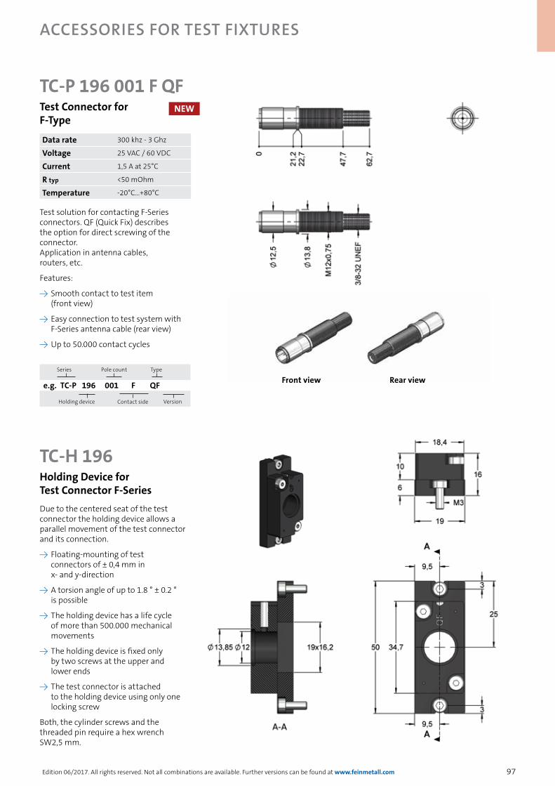
97
accessories for TesT fixTures
Edition 06/2017. All rights reserved. Not all combinations are available. Further versions can be found at www.feinmetall.com
TC-P 196 001 F QFTest Connector for F-Type
Test solution for contacting F-Series connectors. QF (Quick Fix) describes the option for direct screwing of the connector. Application in antenna cables, routers, etc.
Features:
→ Smooth contact to test item (front view)
→ Easy connection to test system with F-Series antenna cable (rear view)
→ Up to 50.000 contact cycles
Data rate 300 khz - 3 Ghz
Voltage 25 VAC / 60 VDC
Current 1,5 A at 25°C
R typ <50 mOhm
Temperature -20°C...+80°C
TC-H 196Holding Device for Test Connector F-Series
Front view Rear view
Due to the centered seat of the test connector the holding device allows a parallel movement of the test connector and its connection.
→ Floating-mounting of test connectors of ± 0,4 mm in x- and y-direction
→ A torsion angle of up to 1.8 ° ± 0.2 ° is possible
→ The holding device has a life cycle of more than 500.000 mechanical movements
→ The holding device is fixed only by two screws at the upper and lower ends
→ The test connector is attached to the holding device using only one locking screw
Both, the cylinder screws and the threaded pin require a hex wrench SW2,5 mm.
NEW
Series
Pole count Type
e.g. TC-P 196 001 F QF
Holding device Contact side
Version

98
accessories for TesT fixTures
Edition 06/2017. All rights reserved. Not all combinations are available. Further versions can be found at www.feinmetall.com
TC-P 201 004 RJ 09Test Connector for RJ-9
Test connector (4 pole) for contacting RJ-9 interfaces. Applications in mini phones, headsets etc.
Features:
→ Smooth contact to test item (front view)
→ Easy connection to test system with RJ-9 cable (rear view)
→ Up to 200.000 contact cycles
Max. Data rate 1 Gbit/s
Voltage 25 VAC / 60 VDC
Current 1,5 A at 25°C
R typ <20 mOhm
Temperature -20°C...+75°C
TC-H 201Holding Device for Test Connector RJ-xx
Front view Rear view
Due to the centered seat of the test connector the holding device allows a parallel movement of the test connector and its connection.
→ Floating-mounting of test connectors of ± 0,4 mm in x- and y-direction
→ A torsion angle of up to 1.8 ° ± 0.2 ° is possible
→ The holding device has a life cycle of more than 500.000 mechanical movements
→ The holding device is fixed only by two screws at the upper and lower ends
→ The test connector is attached to the holding device using only one locking screw
Both, the cylinder screws and the threaded pin require a hex wrench SW2,5 mm.
NEW
Series
Pole count Type
e.g. TC-P 201 004 RJ 09
Holding device Contact side
Version

99
accessories for TesT fixTures
Edition 06/2017. All rights reserved. Not all combinations are available. Further versions can be found at www.feinmetall.com
TC-H 201Holding Device for Test Connector RJ-xx
TC-P 201 006 RJ 11Test Connector for RJ-11
Test connector (6 pole) for contacting RJ-11 interfaces. Applications in data networks, data transmission, power supplies, microphones etc.
Features:
→ Smooth contact to test item (front view)
→ Easy connection to test system with RJ-11 cable (rear view)
→ Up to 200.000 contact cycles
Max. Data rate 1 Gbit/s
Voltage 25 VAC / 60 VDC
Current 1,5 A at 25°C
R typ <20 mOhm
Temperature -20°C...+75°C
Front view Rear view
Due to the centered seat of the test connector the holding device allows a parallel movement of the test connector and its connection.
→ Floating-mounting of test connectors of ± 0,4 mm in x- and y-direction
→ A torsion angle of up to 1.8 ° ± 0.2 ° is possible
→ The holding device has a life cycle of more than 500.000 mechanical movements
→ The holding device is fixed only by two screws at the upper and lower ends
→ The test connector is attached to the holding device using only one locking screw
Both, the cylinder screws and the threaded pin require a hex wrench SW2,5 mm.
NEW
Series
Pole count Type
e.g. TC-P 201 006 RJ 11
Holding device Contact side
Version
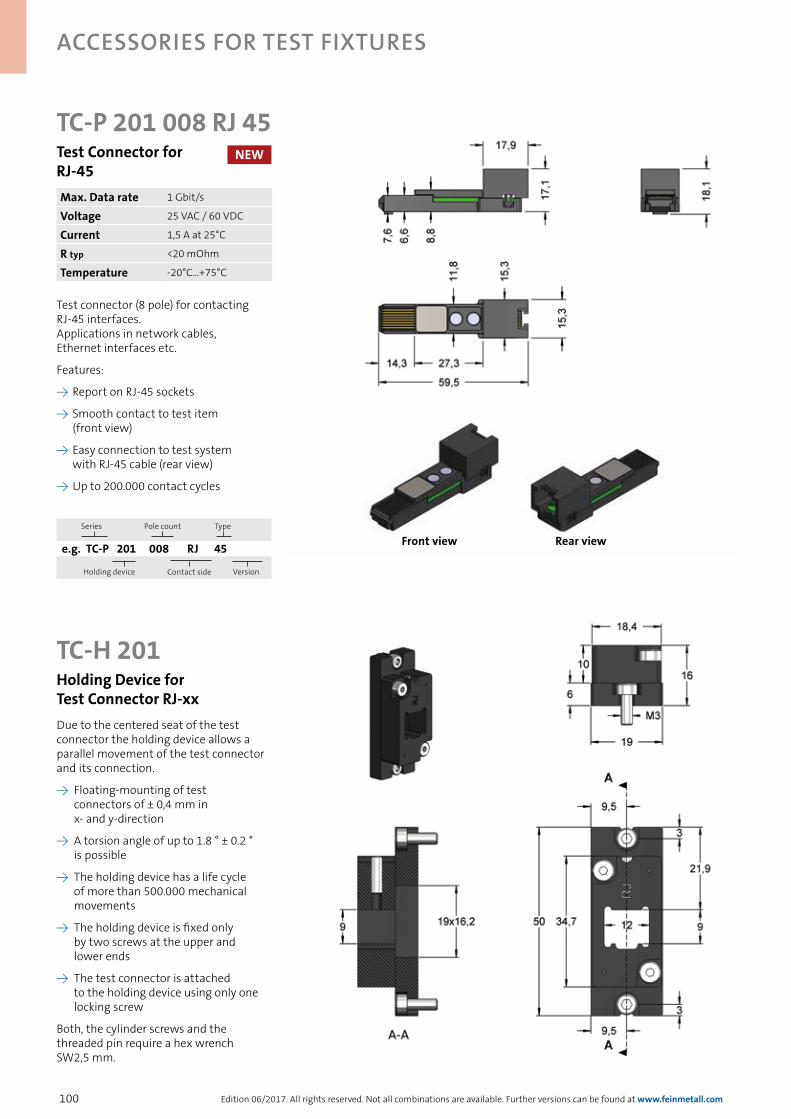
100
accessories for TesT fixTures
Edition 06/2017. All rights reserved. Not all combinations are available. Further versions can be found at www.feinmetall.com
TC-P 201 008 RJ 45Test Connector for RJ-45
Test connector (8 pole) for contacting RJ-45 interfaces. Applications in network cables, Ethernet interfaces etc.
Features:
→ Report on RJ-45 sockets
→ Smooth contact to test item (front view)
→ Easy connection to test system with RJ-45 cable (rear view)
→ Up to 200.000 contact cycles
Max. Data rate 1 Gbit/s
Voltage 25 VAC / 60 VDC
Current 1,5 A at 25°C
R typ <20 mOhm
Temperature -20°C...+75°C
TC-H 201Holding Device for Test Connector RJ-xx
Front view Rear view
Due to the centered seat of the test connector the holding device allows a parallel movement of the test connector and its connection.
→ Floating-mounting of test connectors of ± 0,4 mm in x- and y-direction
→ A torsion angle of up to 1.8 ° ± 0.2 ° is possible
→ The holding device has a life cycle of more than 500.000 mechanical movements
→ The holding device is fixed only by two screws at the upper and lower ends
→ The test connector is attached to the holding device using only one locking screw
Both, the cylinder screws and the threaded pin require a hex wrench SW2,5 mm.
NEW
Series
Pole count Type
e.g. TC-P 201 008 RJ 45
Holding device Contact side
Version
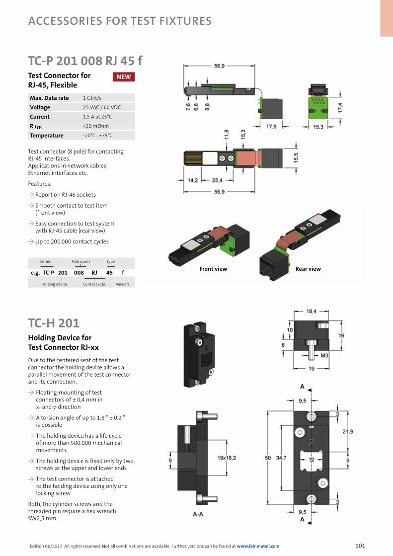
101
accessories for TesT fixTures
Edition 06/2017. All rights reserved. Not all combinations are available. Further versions can be found at www.feinmetall.com
TC-P 201 008 RJ 45 fTest Connector for RJ-45, Flexible
Test connector (8 pole) for contacting RJ-45 Interfaces. Applications in network cables, Ethernet interfaces etc.
Features:
→ Report on RJ-45 sockets
→ Smooth contact to test item (front view)
→ Easy connection to test system with RJ-45 cable (rear view)
→ Up to 200.000 contact cycles
Max. Data rate 1 Gbit/s
Voltage 25 VAC / 60 VDC
Current 1,5 A at 25°C
R typ <20 mOhm
Temperature -20°C...+75°C
TC-H 201Holding Device for Test Connector RJ-xx
Front view Rear view
Due to the centered seat of the test connector the holding device allows a parallel movement of the test connector and its connection.
→ Floating-mounting of test connectors of ± 0,4 mm in x- and y-direction
→ A torsion angle of up to 1.8 ° ± 0.2 ° is possible
→ The holding device has a life cycle of more than 500.000 mechanical movements
→ The holding device is fixed only by two screws at the upper and lower ends
→ The test connector is attached to the holding device using only one locking screw
Both, the cylinder screws and the threaded pin require a hex wrench SW2,5 mm.
NEW
Series
Pole count Type
e.g. TC-P 201 008 RJ 45 f
Holding device Contact side
Version

102
accessories for TesT fixTures
Edition 06/2017. All rights reserved. Not all combinations are available. Further versions can be found at www.feinmetall.com
TC-H 201Holding Device for Test Connector RJ-xx
TC-P 201 010 RJ 50Test Connector for RJ-50
Test solution for RJ-50 connectors (10 pole). Applications in data networks, data transmission, power supplies, microphones etc.
Features:
→ Smooth contact to test item (front view)
→ Easy connection to test system with RJ-50 cable (rear view)
→ Up to 200.000 contact cycles
Max. Data rate 1 Gbit/s
Voltage 25 VAC / 60 VDC
Current 1,5 A at 25°C
R typ <20 mOhm
Temperature -20°C...+75°C
Front view Rear view
Due to the centered seat of the test connector the holding device allows a parallel movement of the test connector and its connection.
→ Floating-mounting of test connectors of ± 0,4 mm in x- and y-direction
→ A torsion angle of up to 1.8 ° ± 0.2 ° is possible
→ The holding device has a life cycle of more than 500.000 mechanical movements
→ The holding device is fixed only by two screws at the upper and lower ends
→ The test connector is attached to the holding device using only one locking screw
Both, the cylinder screws and the threaded pin require a hex wrench SW2,5 mm.
NEW
Series
Pole count Type
e.g. TC-P 201 010 RJ 50
Holding device Contact side
Version
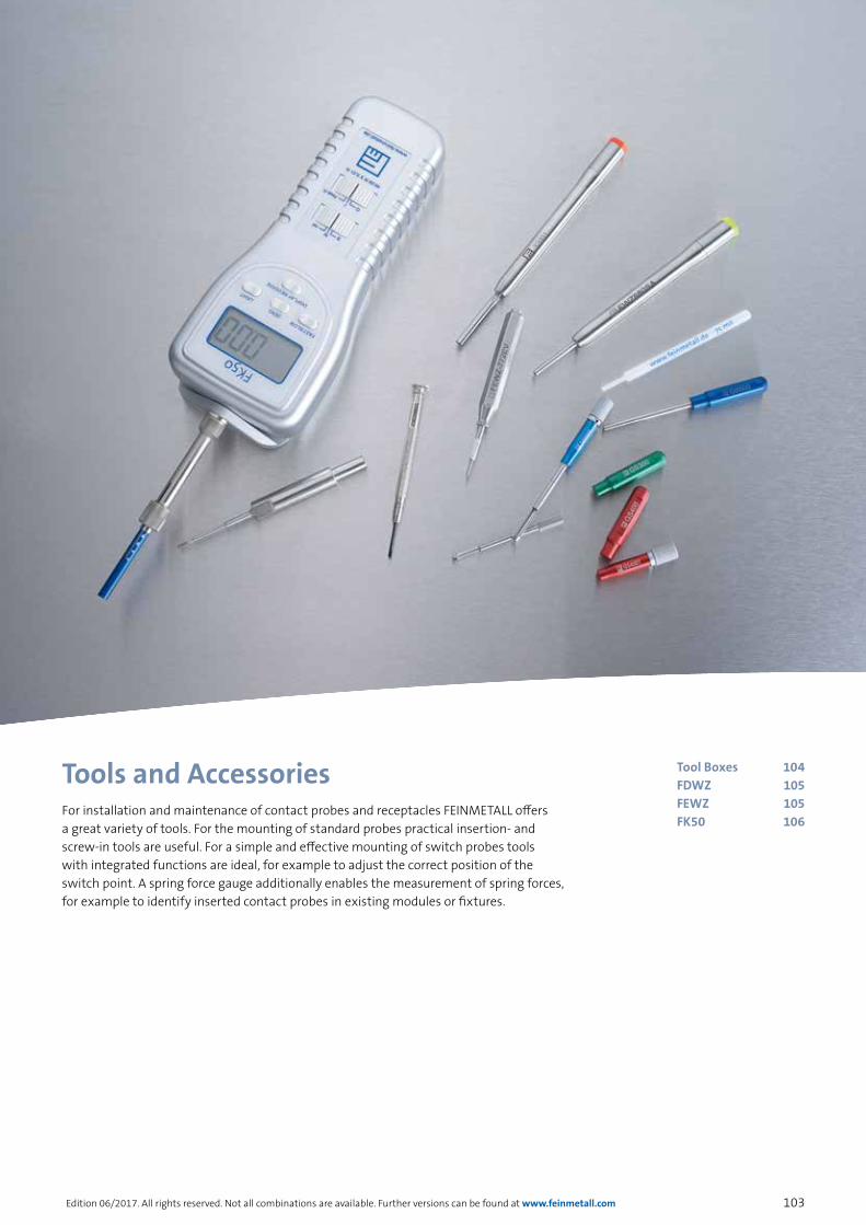
103Edition 06/2017. All rights reserved. Not all combinations are available. Further versions can be found at www.feinmetall.com
For installation and maintenance of contact probes and receptacles FEINMETALL offers a great variety of tools. For the mounting of standard probes practical insertion- and screw-in tools are useful. For a simple and effective mounting of switch probes tools with integrated functions are ideal, for example to adjust the correct position of the switch point. A spring force gauge additionally enables the measurement of spring forces, for example to identify inserted contact probes in existing modules or fixtures.
Tools and Accessories Tool Boxes 104FDWZ 105FEWZ 105FK50 106
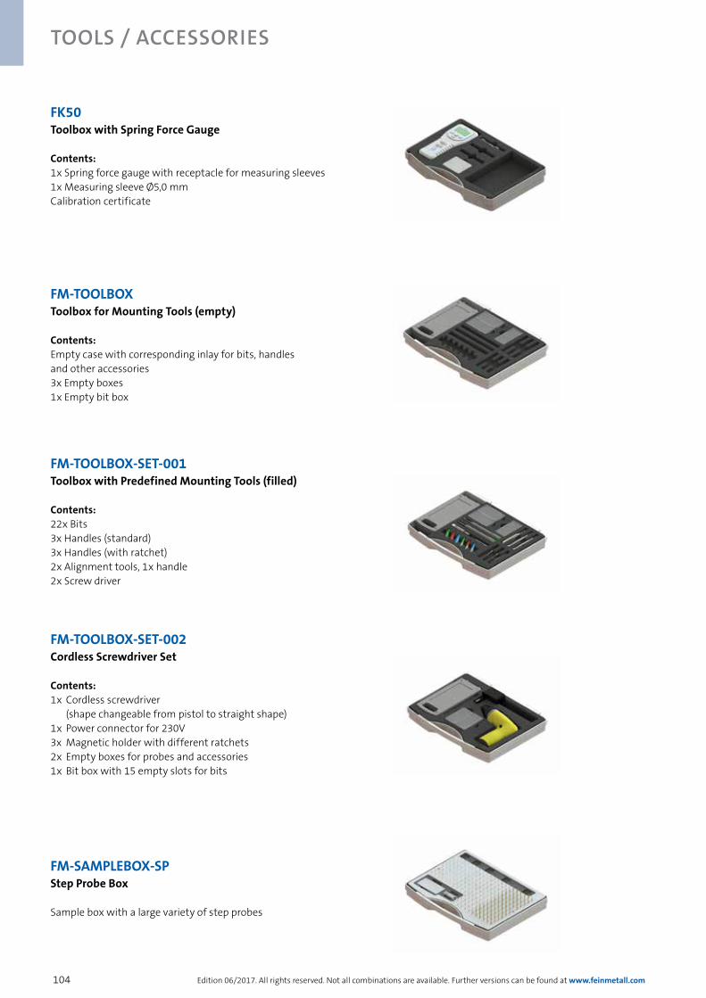
104
Tools / Accessories
Edition 06/2017. All rights reserved. Not all combinations are available. Further versions can be found at www.feinmetall.com
FM-TOOLBOX-SET-001 Toolbox with Predefined Mounting Tools (filled)
Contents:22x Bits 3x Handles (standard)3x Handles (with ratchet)2x Alignment tools, 1x handle2x Screw driver
FM-TOOLBOX-SET-002 Cordless Screwdriver Set Contents:1x Cordless screwdriver (shape changeable from pistol to straight shape)1x Power connector for 230V3x Magnetic holder with different ratchets2x Empty boxes for probes and accessories1x Bit box with 15 empty slots for bits
FK50 Toolbox with Spring Force Gauge Contents:1x Spring force gauge with receptacle for measuring sleeves1x Measuring sleeve Ø5,0 mmCalibration certificate
FM-SAMPLEBOX-SP Step Probe Box Sample box with a large variety of step probes
FM-TOOLBOX Toolbox for Mounting Tools (empty) Contents: Empty case with corresponding inlay for bits, handles and other accessories3x Empty boxes1x Empty bit box

105Edition 06/2017. All rights reserved. Not all combinations are available. Further versions can be found at www.feinmetall.com
tools / aCCessories
All receptacles with dead stop (collar) can be inserted with tool FEWZ-…E0. Press ring at receptacles can be used also as dead stop. The guiding pin of the tool helps to stabilize and properly mount the receptacle.
Insertion tool for receptacles with fixed stop (collar or press ring on top)
Receptacle Insertion height (mm)
PIN-AØ (mm) Insertion tool
H040 0,0 0,63 FEWZ-040E0
H050, H787 0,0 0,80 FEWZ-050E0
H075, H703, H701 0,0 0,90 FEWZ-075E0
H100, H585, H502, H708 0,0 1,30 FEWZ-100E0
H109 0,0 0,50 FEWZ-109E0
H111, H511 0,0 0,60 FEWZ-511E0
H563 0,0 2,00 FEWZ-563E0
H564 0,0 2,40 FEWZ-564E0
H735, H775 0,0 3,50 FEWZ-735E0
H772 0,0 1,60 FEWZ-772E0
H774, H566 0,0 2,6 FEWZ-774E0
All receptacles with press ring can be inserted with tool FEWZ-…Ex. In this case the x is the fix height level (see picture). This value is required for ordering the correct tool. For often changing projection heights the variable tool below is recommended.
Insertion tool for receptacles with press ring (inserted)
Receptacles Insertion height XX required (mm) I-Ø (mm) Insertion tool
H050, H787 xx 1,10 FEWZ-050Exx
H075 xx 1,50 FEWZ-075Exx
H100 xx 1,83 FEWZ-100Exx
For different height levels of the receptacles with inserted press ring, the tool FEWZ-…EV is recommended. The required height level can be adjusted at the tool..
Variable insertion tool for receptacles
Receptacles Insertion height X (mm) Insertion tool
H050, H787 0 - 10 FEWZ-050EV
H075 0 - 12 FEWZ-075EV
H100 0 - 12 FEWZ-100EV
H772 0 - 10 FEWZ-772EV
For inserting the probe into the receptacle tool FDWZ is helpful. After the probe is pushed into the receptacle and stopped by the pressure marks, the probe is driven into the receptacle with the FDWZ tool. The tool is made of a synthetic material to avoid any damaging of the plunger tips.
Insertion tools FDWZ for plug-in contact probes
Insertion tool Shank-Ø (mm) Length (mm)
FDWZ-039 A-Ø=1,00; I-Ø=0,55 67,50
FDWZ-050 1,50 100,0
FDWZ-075 2,50 100,0
FDWZ-100 3,50 100,0
FDWZ-650 A-Ø=6,00; I-Ø=4,10 100,0

106
Tools / Accessories
Edition 06/2017. All rights reserved. Not all combinations are available. Further versions can be found at www.feinmetall.com
Measuring sleeve Order code for series Inner-Ø A [mm]
Outer-Ø B [mm]
Projection Height [mm]
Nominal travel [mm]
Measuring sleeve F732 MS230E065 F732 2,30 2,70 10,50 4,00
Measuring sleeve F733 MS360E065 F733 3,60 4,00 10,50 4,00
Measuring sleeve VF3 MS270E355 VF3 2,70 3,20 40,50 5,00
Measuring sleeve VF4 MS370E355 VF4 3,70 4,20 40,50 5,00
Measuring sleeve VF5 MS460E315 VF5 4,60 5,00 36,50 4,80
FK50 Spring Force GaugeThe Spring Force Gauge allows force measurement at all types of spring contact probes up to 50 N. This instrument allows in a very simple way to verify, if a probe is still intact and to determine the spring force of the probe. The measuring results are displayed at the instrument and the display can be electrically turned by 180° if needed, e.g. for overhead applications. For the measurement just put the measuring sleeve over the probe and push it to the mounting plate. The sleeves depth can be adjusted according to the projection height of the probe. Adjustable measuring sleeves are available with three different diameters.
Technical SpecificationsMinimum force: 3g / 0,10oz / 0,03NResolution: 1g / 0,03oz / 0,01NMeasuring accuracy: +/- 0,5% at 25°CData output: via RS 232 (order code 2111810)Power supply: 6 x 1,5V AA (UM-3 batteries) (Batteries non included in delivery)
Included in Delivery:→ Spring Force Gauge with receptacle for measuring sleeve→ Measuring sleeve Ø 5,0mm→ Calibration certificate→ Carrying case
Rigid measuring sleeves with fixed stop Rigid measuring sleeves for repeating measurements at probes with fixed projection height are available with different diameters.
Example for height adjustment at measuring sleeve
Projection height of probe, e.g. F732:Nominal:Projection height - nominal:Value of height to fix:
= 10,50 mm= 4,00 mm = 10,50 - 4,00 mm= 6,50 mm
Dimensions of adjustable measuring sleeves
Measuring sleeve
Inner-Ø A [mm]
Outer-Ø B [mm]
Height adjustable from/to [mm]
MS30 3,00 4,00 0 - 40,50
MS40 4,00 5,00 0 - 40,50
MS50 5,00 6,00 0 - 40,50
Description Order code
Spring force gauge FK50 FK50
Measuring sleeve Ø 3,0 mm MS30
Measuring sleeve Ø 4,0 mm MS40
Measuring sleeve Ø 5,0 mm MS50
Data cable RS232 2111810
Operating manual available on the homepage.

107
Application Specific Catalogs
In order to find the right contact probe for your application quickly and at a glance, we have now created four application specific catalogs with appropriate contact probes, including many technical details and application notes.
the right Catalogue for eaCh appliCation
All catalogs and brochures are available on our homepagehttp://www.feinmetall.com/downloads/catalogues-and-flyers/
contact probesfor wire harness test
switch probes step probes
threaded probes push back probes
Vers
ion
1
contact probesfor pcb testing
probes for ict and fct interface probes
position testaccessories for test fixtures
Vers
ion
1
contact probesfor fine pitches for low heights and for direct soldering
fine pitch probes battery contacts
short travel probes
Vers
ion
1
contact probesfor high current, kelvin 4-wire- and radio frequency messurement
high current probes kelvin probes radio frequency probes
Vers
ion
1

Vers
ion
1
S
ubje
ct to
cha
nge
wit
hout
not
ice
GO
-gra
fik.
de
www.feinmetall.com
You can find all representations worldwide on our homepage www.feinmetall.comOur sales offices are perfectly connected to the markets and work in close cooperation with our customers. Most important for us is a high quality - regarding our products as well as regarding our customer support.
Our strengths → Native-speaking contacts in many countries enable ideal communication → Application engineers take care of customer projects → Active key account management provides customer specific know-how → Teamwork of product managers and local sales engineers facilitate innovative and customized solutions → Periodic technical trainings make sure that sales teams have a high level of competence → Technical key customer trainings enhances know-how transfer to end users
These strengths have already resulted in many successful and innovative projects. FEINMETALL is already rated as preferred supplier for many notable companies. Our strong customer support is your advantage.
wOrLdwIdE PrESENT FOr yOu
FM Subsidiaries representations
FEINMETALL GMBH | HErrENBErG, GErMANy(+49) 7032 2001-0 | [email protected]
FEINMETALL dE MExIcO | MExIcO(+52) 55 2591 0629 | [email protected]
FEINMETALL SINGAPOrE PTE LTd | SINGAPOrE(+65) 6316 4544 | [email protected]
FEINMETALL SHANGHAI | cHINA(+86) 21 2898 6848 | [email protected]
FEINMETALL uSA LLc | SAN JOSE, uSA(+1) 408 432 7500 | [email protected]
FEINMETALL-OcT | HSINcHu cOuNTy, TAIwAN(+886) 3 560 15 66 | [email protected]
FEINMETALL cZ | cZEcH rEPuBLIc(+42) 0491 470-511 | [email protected]
FM Subsidiaries: