construction control technology of cast-in-place foot
TRANSCRIPT

Construction Control Technology of Cast-in-place Foot Section on Arch Aqueduct Using Cantilever Erection Method
construction control technology of arch foot cast-in-place section Wenping Peng 1, a, Zhongchu Tian 2,b
1Changsha university of Science and Technology,Changsha,Hunan,China 2 Changsha university of Science and Technology,Changsha,Hunan,China
[email protected], [email protected]
Keywords: Arch aqueduct; Prefabrication and lifting; Construction control; Construction joint. Abstract. Longchang Aqueduct is a reinforced concrete box deck type arch with clear span 200m,located in Guizhou Province of China, inclined cable-stayed buckle and cantilever erection is adopted for rib assemble. This paper introduces the arch ring of arch foot section of the construction of a unique process, the Reverse tension Bailey truss method, based on two different casting scheme comparisons, the key of the construction control parameters of the technology is put forward. It is of guiding function for engineering practice.
Introduction The segmental precast arch ring, using the cable erection with cable-stayed buckle construction of
arch aqueduct are rare. Longchang aqueduct, the key in Central Guizhou’s Hydro-junction, is a deck arch aqueduct with a single span of 200m. The aqueduct is famous for its span size and hoisting capacity, designed for 300kN. It is difficult to control the cable forces and the arch rib alignment during the construction process. In this paper, the main arch ring of Longchang aqueduct construction control of the key technologies are introduced, providing reference for similar bridge construction. In this paper, the cast-in-place foot section of Longchang aqueduct construction control technologies are introduced, providing reference for similar bridge construction.
Engineering Background Longchang aqueduct is a single span arch aqueduct, the first phase of central Guizhou water
conservancy key project in Guizhou, one of the biggest span arch aqueduct in China’s water conservancy industry. Long chang aqueduct’s main arch ring is a reinforced concrete box arch of single box with double chamber, with a clear span of 200m. A net arrowheight of 40m and a rise-span ratio of 1/5(Fig.1). The arch axis of the main arch ring is set up to a catenary with arch-axis coefficient m=2.240. The section of arch box is a variable cross-section, has a width from 12m gradually change to 5.5m(Fig.2),a height of 3.5m, and a thickness of roof and floor of 40cm. Boundary web plate is 60cm,and medium web plate is 40cm. The main arch ring is made of C55 concrete, 0# cast-in-situ section is poured on reversely-pulled bailey truss. The rest is divided to 13 sections per half-span, constructed by cable erection and strayed knotting method. Mid-span closure segment has a length of 0.8m is cast-in-place.
Arch ring 0# section uses the bailey truss reverse pulling cast-in-place method, while segments 1#-13# use precast and hoisting, vault setting stiff skeleton closure segments. For each segment, the installation sequence is to complete casting immediately on the current section with the previous section of joints after that joint reaches more than 85% of the design strength of concrete, before lifting the next section. The whole precasting and cantilever (cable hoisting with suspension process) installation plan is used in the main arch ring. The arch ring is divided into 26 precast segments simplifying construction and installation safety horizontal to the overall prefabricated box. The prefabricated segment size is according to the biggest cable hoisting system of 3000kN (based on a
7th International Conference on Energy and Environmental Protection (ICEEP 2018)
Copyright © 2018, the Authors. Published by Atlantis Press. This is an open access article under the CC BY-NC license (http://creativecommons.org/licenses/by-nc/4.0/).
Advances in Engineering Research, volume 170
975

single section shell weight of 1425kN, so 1500kN for a single set of main cable lifting). The length of single section precast is 15m of arch foot horizontal projection using reverse pulling bailey truss cast-in-place, the rest according to the division of cable hoisting system lifting tonnage segment, segment with the heaviest weight is 2413kN and the lightest weight is 1942kN. After every section’s installation, the precast box section will be in front of the segment joint of cast-in-place concrete casting, increasing the rigidity of the arch rings and joints, ensuring construction safety.
330000(15000×22)
clear span200000
Tank shell segment
▽1241.500 X
Y
O
C55concrete
1:0.3
C
▽1281.316
▽1267.306
▽1252.796
▽1277.616
▽1268.626
1:0.3
Figure 1. Elevations layout of Longchang aqueduct (unit: mm)
center line of arch aixs
Expand along theoretical arch axis
19695 5568 5426 5879 5756 5640 6637 7576 7448 7859 8262 8187 8629 8710 4030 1 2
center line of Segment
3 4 5 6 7 8 9 10 11 12 13
1200
0
5500
111675
late poured band
1:2
400
650
650
403
Figure 2. Floorplan of Longchang aqueduct (unit: mm)
Longchang aqueduct’s main arch ring is devided into 29 sections and constructed by the method of prefabrication and lifting. 0# cast-in-situ section is poured on reversely-pulled bailey truss. The rest is constructed by whole prefabrication and cable erection method. After one segment lifting complete, it would be cable-stayed buckled for a short time, and then, beginning the next cycle. The steel buckled towers are build on the two borderline piers with steel pipe truss structure, have a height of 27m,its main compressed structure is made up of eight Ф630×20mm steel tubes. The tension anchor beam is constituted by I50 joist steel. 0#~6# supporting cable layered hang on the borderline pier, 7#~13# supporting cable layered hang on steel buckled towers’ each anchor point. Cable erection system and cable-stayed buckle system(Fig.3).
Main cableanchoring
Tunnel
fmax=L/12.5
550000 120000
water channel
Lifting cablePulling cable
Main cable
Figure 3. Arrangement drawing of Longchang aqueduct (unit: mm)
Main construction process of 0# cast-in-place segment Cast-in-site segment arc arch ring 0# 19.695m, adopt bailey truss counter loop construction(Fig.4).
Bailey truss assembly along the axis of the aqueduct, The Bailey truss articulated on arch foot, finish rolled threaded reinforcing bar as a rigid connection counter pull Bailey truss on the borderline pier. The back anchor cables on borderline pier adopts steel strand anchor in mountain anchor cables. Counter loop rigid bar is divided into two parts. One part arrangement near the end of the outside Bailey truss called 1# bar, composed of eight set of tie bar, another part arrangement in the central of the Bailey truss called 2# bar, is made up of six groups of tie bar. The borderline pier anchor cable
Advances in Engineering Research, volume 170
976

made up of five groups of prestressed steel strand, corresponding tie rod boundary pier at the front two rows of to ensure pier deviation under controlled.
The 3.5m high main arch ring section, in order to ensure the concrete vibratory compaction, to control the hydration heat, to ensure the quality of concrete pouring, to ring pouring, is divided into three ring, divided into arch ring floor, arch ring webs and arch ring roof. Split ring pattern as shown in figure 5.
Figure 4 Cast-in-place Segment arrangement
700
2100
700
3500
Figure 5 Cast-in-place Segment layered pouring
Table 1 Construction process of 0# cast-in-place segment by no Later pouring blocks Process order Plan A
1 assemble bailey truss, tension #1and #2 precision-rolled reinforced bars and #2 anchor cables
2 install the bottom die, tie plate steel, casting floor 3 tension #1 anchor cables 4 bind reinforcement web, pour the web
5 cables force adjustment, tension #1 and #2 precision-rolled reinforced bars and #2 anchor cables, base plate of arch ring
6 bind steel roofs, pour roofs
7 system transformation, dismantle temporary buckle, anchor cables, install permanent buckle and anchor cables
Table 2 Construction process of 0# cast-in-place segment by later pouring blocks .
Process order Plan B
1 assemble Bailey truss tension #1, #2 precision-rolled reinforced bars and #2 anchor cables
2 install the bottom die, tie plate steel, casting floor 3 Tension #1 anchor cables 4 bind reinforcement web, pour the web 5 bind steel roofs, pour roofs
Advances in Engineering Research, volume 170
977
6 place later pouring blocks
7 system transformation, dismantle temporary buckle, anchor cables, install permanent buckle and anchor cables
Pouring schemes comparison From the concrete internal stress state, with ring pouring, reserved later pouring blocks can
guarantee concrete in stressless state, which can effectively prevent the concrete from beginning to crack.
The posterior segments scheme will be because the base plate after forming, skewback consolidation, the webs pouring load by the base plate and the bailey truss joint, under heavy load on the skewback bottom plate upper has tensile stress, maximum tensile stress is 1.70MPa. When the web plate casting is completed, the opening-box is formed, roof load by opening-box and bailey truss joint, opening-box upper arch feet also will develop tensile stress. To prevent roof pouring, continue to apply tensile stress in the crack of the arch foot. After the completion of the web plate casting, add a second line through the stress state of the cable force adjustment opening-box to decrease the tensile stress in the flange on the arch foot. After the procedure, which can effectively control tensile stress in the arch ring within 1.92MPa, the requirement of class A component cracks are satisfied.
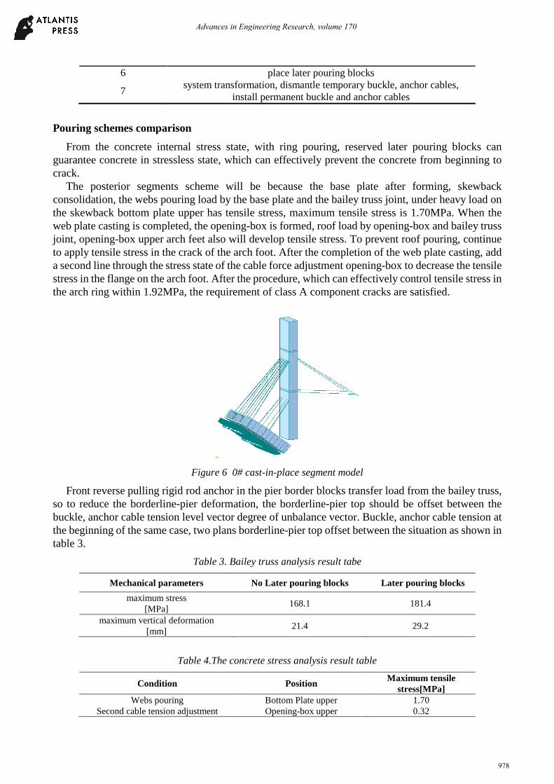
Figure 6 0# cast-in-place segment model
Front reverse pulling rigid rod anchor in the pier border blocks transfer load from the bailey truss, so to reduce the borderline-pier deformation, the borderline-pier top should be offset between the buckle, anchor cable tension level vector degree of unbalance vector. Buckle, anchor cable tension at the beginning of the same case, two plans borderline-pier top offset between the situation as shown in table 3.
Table 3. Bailey truss analysis result tabe
Mechanical parameters No Later pouring blocks Later pouring blocks maximum stress
[MPa] 168.1 181.4
maximum vertical deformation [mm] 21.4 29.2
Table 4.The concrete stress analysis result table
Condition Position Maximum tensile stress[MPa]
Webs pouring Bottom Plate upper 1.70 Second cable tension adjustment Opening-box upper 0.32
Advances in Engineering Research, volume 170
978

Table 5.The concrete stress analysis result table
Schemes Maximum pier top offset[mm]
1 No later pouring blocks 7.2
2 Later pouring blocks 14
The results can be seen in table 3, Scheme 1’s pier top offset is smaller. Therefore, under the
condition of the same initial tension, Scheme 2, the rigid rod is passed to the borderline-pier load is bigger. Given the above analysis result, the reserve later pouring blocks of structure with the overall stress distribution is bad. Later pouring blocks can make the arch ring be in a state of stress, without considering the arch ring tension. Through the stress analysis, the secondary adjustable cord to adjust the stress state of the arch ring can effectively prevent cracking tensile stress if the arch ring is too large. After considering the difficulty the no later pouring blocks scheme is more suitable. This concrete pouring is achieved through reverse pulling bailey truss cast-in-place method which combines the support cast-in-place with cable-stayed, has its unique mechanical characteristics. In construction control, therefore, not only is there a need to analyze the force of the support structure itself, but also a need to consider the stress state of the concrete pier offset between them both. The key parameters for its reasonable structure in the process of control can guarantee the construction safety and reliability.
Conclusions With reverse pulling bailey truss cast-in-place construction, no later pouring blocks is acceptable. Using the method of twice adjustable concrete stress is feasible, effectively preventing the stratified pouring in the process of the cracks of the concrete stress.
Acknowledgements This work was financially supported by the National Natural Science Foundation of China (51478049).
References [1] The ministry of communications of the People's Republic of China. Code of design for reinforced and prestressed concrete highway bridges (JTG D62-2004)[S]. Beijing. people's traffic press, 2004
[2] Li Zhe, Zhao Dongsheng, Yan Donghuang. Large span concrete filled steel tubular arch bridge manufacturing linear calculation method for the study [J]. Chinese and foreign road,2015, (35)
[3] Cai Ze. Concrete filled steel tubular arch bridge arch rib arch setting and construction control.[J].Modern industrial economy and information technology, 2015, (11)
[4] Qian Jianzhang, Zhou Yiqiao. By the methods of long term and short term precast prestressed concrete box girder section[J]. Highway traffic technology,2003, (5)
[5] Liu Wanzhong, Wang Jiejun. The cantilever construction of reinforced concrete arch bridge construction control[J]. Highway traffic science and technology, 2003, (6). 69-72
[6] Shi Jing, Gao Jianqi. Continuous box girder bracket of bailey truss cast-in-situ construction technology[J]. Road construction machinery and construction mechanization. 2011,(9). 73-75
Advances in Engineering Research, volume 170
979