consortium partners - promeca official...
TRANSCRIPT

ENERGY ANALYSIS AND MODELING OF MEMBRANE REACTORSPROMECA Workshop 2017
ENERGY ANALYSIS AND MODELING OF MEMBRANE REACTORS
PROMECA Workshop 2017
Consortium Partners
Director, Institute for Micro Process Engineering (IMVT), Karlsruhe Institute of Technology (KIT), Karlsruhe, Germany
Roland Dittmeyer
Ultra-compact micro structured palladium membrane reactors for hydrogen production
Institute for Micro Process Engineering (IMVT)

1. Introduction – Micro structured membrane reactors for hydrogen production
2. On-site steam methane reforming – The µ-Enhancer
3. Dehydrogenation of liquid organic hydrogen carriers – The system MCH / TOL
4. Simplified modeling of a micro channel membrane reactor will wall-coated catalyst
1.Derivation of the governing equations
2.Flexible solution using Matlab®
5. Some points to remember
AGENDA
02

SMALL CAPACITY HYDROGEN SUPPLY AN OPPORTUNITY FOR NEW TECHNOLOGY SUCH AS
MEMBRANE REACTORS
03
Small quantities (<500m³/h)
low pressure H2 (<3bar)
medium grade H2 (>99,95%)
Customer
Transport
Hydrogen supply< 500 m³/h
on-site
Hydrogen supply < 80.000 m³/hHigh pressure and purity (~10-20 bar, >99.999%)
Dittmeyer & Schödel, ICCMR-11, 2013

WHY MEMBRANE REACTORS IN HYDROGEN PRODUCTION?
04
• Equilibrium shift• Integrated purification
Steam methane reforming
Natural gas
Desul- furizer
Steam
Reformer
H2
Shift Converter
PSA
Buffer tank Steam
H2
Membrane reformer
NG
more energy-efficient, lower OPEX
simpler process, reduced CAPEX

BENCHMARK IN MEMBRANE-ASSISTED SMR
05
Modular reformer system: 40 mN
3/h H2
Tokyo Gas Modules:
Senju hydrogen station, Tokyo
Yasuda et al., 2005, ICCMR-7, Cetraro
Kurokawa et al., 2010, Demonstration of Highly-Efficient Distributed Hydrogen Production from Natural Gas with CO2Capture, WHEC2010, Essen

WHY MICRO FABRICATION?
06
Membrane
Benefits:•Very large membrane surface area per catalyst volume (ca. 103 – 106 m-1)•Negligible mass transport resistance towards membrane even for high-flux membranes•Efficient heating by hot gas or catalytic combustion of retentate with air•High compactness / low weight / modular plant design

07
KIT‘s µ-EnH2ancer project
• Preparation of defect-free membranes• Concepts for thermal and mechanical stability
• Membrane integration by laser welding• H2 permeation experiments• Mass transport performance 3)
• Preparation of Rh/Al2O3 catalysts• Activity and stability tests• Reaction kinetics without membrane In
tegr
atio
n in
a te
chni
cal
reac
tor b
y la
ser w
eldi
ng
1) Boeltken et al., CE&P: Process Intensif. 67 (2013) 136-1472) Lee et al., Appl. Catal. A:Gen. 467 (2013) 69-753) Boeltken et al., J. Membr. Sci. 468 (2014) 233-2414) Boeltken et al., Int. J. Hydr. Energy 41 (2014) 18058-18068

08
MODULAR MEMBRANE REACTOR DESIGN
Pre-reforming stage• Cracking of higher hydrocarbons (natural gas)• Build-up of H2 partial pressure (by reforming)Reforming stage• Reforming• H2 separationRetentate combustion zone• Heat transfer to the reforming zone
09
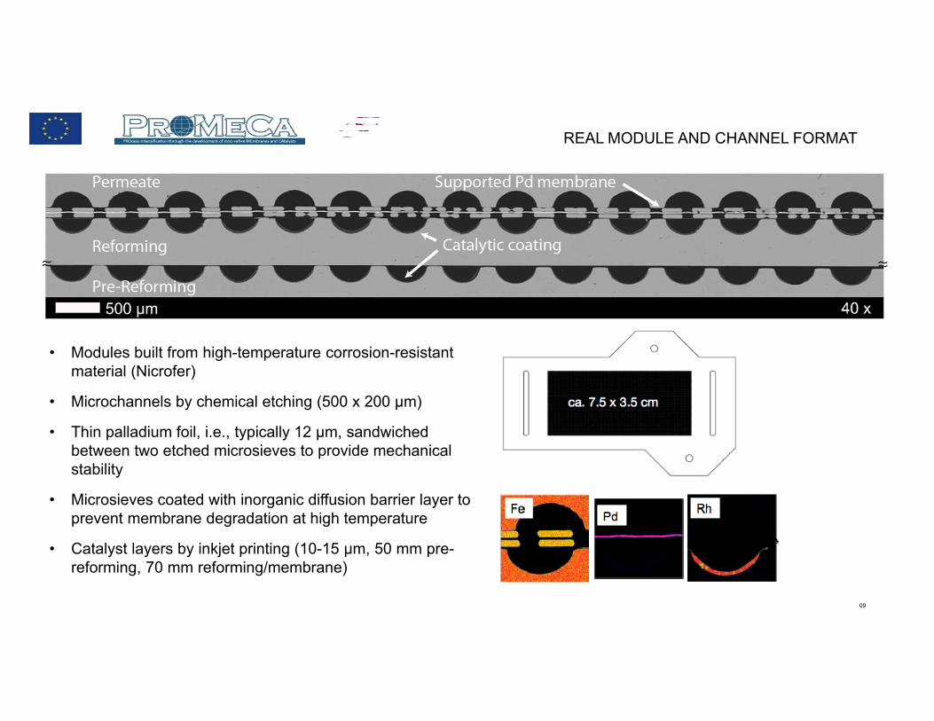
REAL MODULE AND CHANNEL FORMAT
• Modules built from high-temperature corrosion-resistant material (Nicrofer)
• Microchannels by chemical etching (500 x 200 µm)
• Thin palladium foil, i.e., typically 12 µm, sandwiched between two etched microsieves to provide mechanical stability
• Microsieves coated with inorganic diffusion barrier layer to prevent membrane degradation at high temperature
• Catalyst layers by inkjet printing (10-15 µm, 50 mm pre-reforming, 70 mm reforming/membrane)

010
SELECTED RESULTS - CONVERSION VERSUS HYDROGEN RECOVERY
Variation of retentate pressure; W/F = 0.33 gCat h / mol CH4; S/C = 3
Conversion is close to equilibrium considering the fraction of hydrogen removed
Activity of catalyst high enough to respond to H2 removal
Boeltken et al., Int. J. Hydr. Energy, 2014, 39, 18058-18068.
011
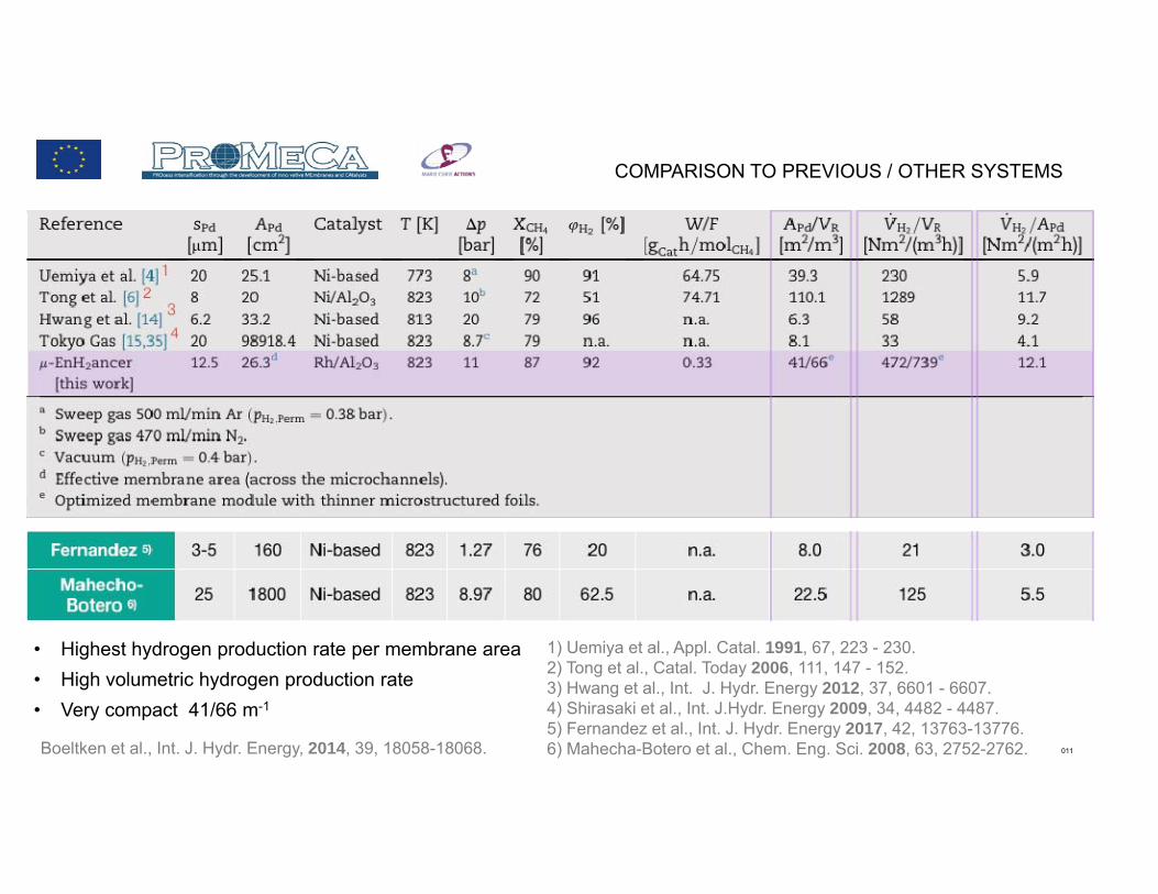
COMPARISON TO PREVIOUS / OTHER SYSTEMS
• Highest hydrogen production rate per membrane area• High volumetric hydrogen production rate• Very compact 41/66 m-1
1) Uemiya et al., Appl. Catal. 1991, 67, 223 - 230. 2) Tong et al., Catal. Today 2006, 111, 147 - 152. 3) Hwang et al., Int. J. Hydr. Energy 2012, 37, 6601 - 6607. 4) Shirasaki et al., Int. J.Hydr. Energy 2009, 34, 4482 - 4487. 5) Fernandez et al., Int. J. Hydr. Energy 2017, 42, 13763-13776.6) Mahecha-Botero et al., Chem. Eng. Sci. 2008, 63, 2752-2762. Boeltken et al., Int. J. Hydr. Energy, 2014, 39, 18058-18068.

012
NEW SYSTEM WITH FLUIDIC HEATING ESTABLISHED
Dittmeyer et al., ICIM-14 2016

013
NEW MODULES
• all plates fabricated • microchannel plates awaiting coating with new catalyst• new porous metal-supported membranes in preparation
Dittmeyer et al., ICCMR-13 2017

014
IMRET 2018, OCT. 21-24, KARLSRUHE

015
RH/AL2O3 CATALYSTS BY FLAME SPRAY PYROLYSIS
Catalyst
Rh
loadinga
(%)
H2 chemisorption results TEM results
Rh active sites
(Achem)b
(μmol/gcat)
Rh dis-
persionc
(%)
Rh particle
size (Pchem)d
(nm)
Rh particle
size (PTEM)e
(nm)
Rh active sites
(ATEM)f
(μmol/gcat)
5Rh/FAl 3.85 174 47 2.4 1.6 290
5Rh/SAl 2.75 117 44 2.5 3.5 90
1Rh/FAl 0.94 69 75 1.5 1.0 105
1Rh/SAl 0.84 59 73 1.5 1.7 53
0.2Rh/FAl 0.20 13 69 1.6 -- --
0.2Rh/SAl 0.20 12 61 1.8 -- --
a Rh loading derived from ICP-OES. b From H2 uptake in chemisorption assuming
a stoichiometry of H/Rh = 1. c Ratio of active Rh from H2 chemisorption
and Rh content from ICP-OES. d From metal dispersion by H2 chemisorption. e From TEM measurements.f Derived from TEM results.
Yu et al., Appl. Catal. B: Environ. 2016, 198, 171–179.

016
PLANAR METAL-SUPPORTED PD MEMBRANES
In cooperation with Forschungszentrum Jülich (Martin Bram, IEK-1)
Test specimen
48,0
22,8
48,0
20,6
35,0
9,8
7,6
48,0
22,8
48,0
20,6
35,0
9,8
7,6
Transfer to membrane reformer modules
Testing unit
• Pd: ca. 4 - 12 µm (foil or SPS coating)
• 8-YSZ: ca. 20 - 40 µm• Sinter metal: ca. 1 mm
Boeltken et al., CE&P 2013, 67,136-147Dittmeyer et al., ICCMR-13 2017
Concept
017
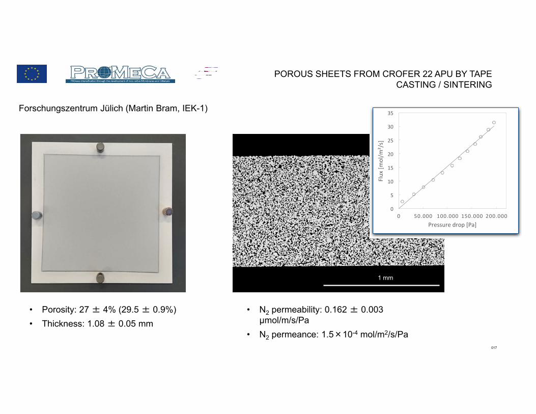
POROUS SHEETS FROM CROFER 22 APU BY TAPE CASTING / SINTERING
1 mm
0
5
10
15
20
25
30
35
0 50.000 100.000 150.000 200.000
Flux
[mol/m
²/s]
Pressure drop [Pa]
• Porosity: 27 ± 4% (29.5 ± 0.9%)• Thickness: 1.08 ± 0.05 mm
• N2 permeability: 0.162 ± 0.003 µmol/m/s/Pa
• N2 permeance: 1.5×10⁻⁴ mol/m2/s/Pa
Forschungszentrum Jülich (Martin Bram, IEK-1)

018
COATING WITH POROUS 8YSZ
Forschungszentrum Jülich (Martin Bram, IEK-1, Paul Kant, IMVT)

019
Forschungszentrum Jülich (Martin Bram, IEK-1, Paul Kant, IMVT)
0,000
0,005
0,010
0,015
0,020
0,025
0,030
0,035
0 5 10 15 20 25
Layer thickne
ss [m
m]
Posi9on in mm
single coa9ng
double coa9ng
Layer thickness derived from SEM (MatlabⓇ routine)
SINGLE VERSUS DOUBLE LAYER COATING
020
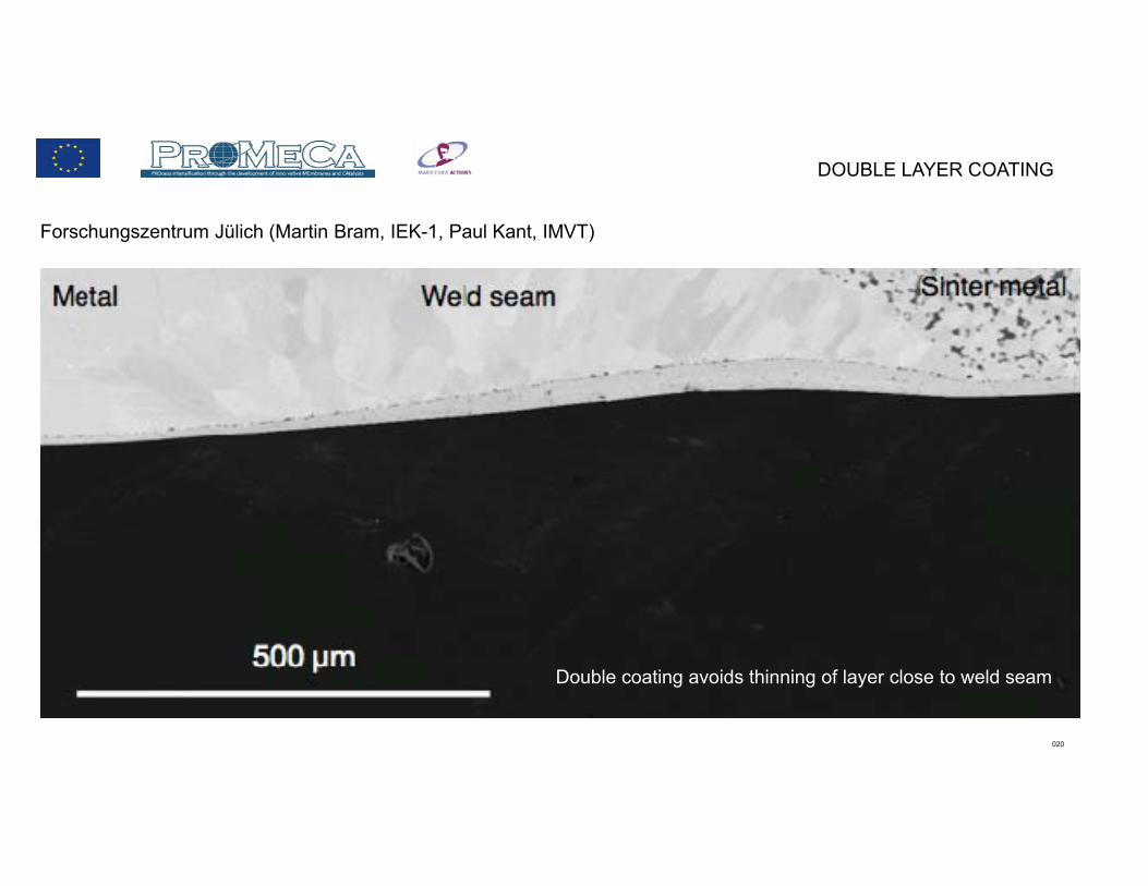
DOUBLE LAYER COATING
Forschungszentrum Jülich (Martin Bram, IEK-1, Paul Kant, IMVT)
Double coating avoids thinning of layer close to weld seam

021
DOUBLE LAYER COATING
Forschungszentrum Jülich (Martin Bram, IEK-1, Paul Kant, IMVT)
Nice smooth surface for coating with thin Pd or Pd alloy layer

022
SUSPENSION PLASMA SPRAYING OF PD NANOPARTICLES
In cooperation with the German Aerospace Center (Sayed-Asif Ansar, Dirk Ullmer, TT, Stuttgart)
• Stable suspension of Pd nanoparticles obtained
• Injection system and plasma parameters being optimised
• First coating experiments performed on test specimen (Pd layers are not yet gastight)
• Transfer to membrane reformer modules
Boeltken et al., J. Membr. Sci. 2014, 468, 233-241.

023
BENEFITS OF POROUS SUPPORT
Boeltken et al., J. Membr. Sci. 2014, 468, 233-241.
• Higher pressure improves H2 permeation flux • The is key to high H2 production rate per volume
Pd foil on porous support
1st generation system

024
MEMBRANE MICROREACTOR FOR MCH DEHYDROGENATION
Application background
Liquid organic reaction cycle (LORC) for long-term storage of intermediate temperature heat
Kreuder et al., Catal. Today, 2015, 242, 211-220.
MCH dehydrogenation to toluene:
Catalyst: 1 wt.-% Pt/γ-Al2O3

025
Microchannel Reactor – Catalyst testing
Kreuder et al., Catal. Today, 2015, 242, 211-220.
Influence of pressure on the deactivation rate. T = 325°C. modified contact time W/F 4000 kg s m-3 (1 bar) and 750 kg s m-3 (9 bar). MCH/N2 50/50.
• Kinetic studies in BERTY-type recycle reactor showed much slower deactivation by carbon formation

026
Micro Packed-Bed Membrane Reactor – First Design
Kreuder et al., Int. J. Hydr. Energy, 2016, 41, 12082-12092.

027
CATALYST DEACTIVATION BY COKING
Micro membrane reactor Berty-type recycle reactor Micro channel reactor
Time [min]
Con
vers
ion
[%]
Eq, 9 bar
Eq, 1 bar
Effect of hydrogen on deactivation. W/F = 250 kg s m-3.
Carbon content stable around 0.8 wt.-% (TGA, 400°C, BERTY reactor, up to 25 h)
350°C, 9 barback permeation of H2 in entrance region
348°C, 1 barperfect back mixing, i.e., H2concentration at reactor effluent level
400°C, 9 bar no back mixing, i.e., low H2 partial pressure in entrance region
after use
fresh

028
REGNERATION IN PLACE
Procedure• 1 h treatment in a flow of 5 ml/min air plus 50 ml/min N2 for during off the deposits• 1 h treatment in a flow of 50 ml/min H2 for reduction of the catalyst surface
T = 400°C. PRet = 9 bar. W/F = 250 kg·s·m-3. XEq. = 99%.
Kreuder et al., Int. J. Hydr. Energy, 2016, 41, 12082-12092.

029
MODIFIED PACKED-BED DESIGN
Reduced bed height of 0.5 mm / enlarged area
Kreuder et al., Int. J. Hydr. Energy, 2016, 41, 12082-12092.
0 500 1000 1500 2000 25000.0
0.2
0.4
0.6
0.8
1.0
Conversion H2 recovery factor
tos / min
Con
vers
ion
/ -
0.0
0.2
0.4
0.6
0.8
1.031 bar28 bar25 bar
Hyd
roge
n re
cove
ry fa
ctor
/ - On-going work:
• Further optimisation of reactor geometry based on simulations (optimised bed height, longer packed bed section).
• Catalyst improvement regarding coking.
• Scale-up and test in integrated process.
T = 350°C. PRet = 28-31 bar. W/F = 125 kg·s·m-3.

030
WALL-COATED REACTION CHANNEL - UNIVERSAL APPROACH

031
FREE CHANNEL VOLUME
CSTR material balance for component i:
0 q(x) ci (x) q(x dx) ci (x dx) ji (x dx) A
0 u(x) ci (x) u(x dx) ci (x dx) w h kig ci*(x dx) ci (x dx) w dx

032
FREE CHANNEL VOLUME
u(x dx) w h u(x) w h kig ci*(x dx) ci (x dx)
i
w dx RT
p
new flow velocity u(x+dx) for ideal gas and constant pressure:
total volume flow to/from layer
total molar flux to/from layer
u(x dx) u(x) dxhRTp
kig ci*(x dx) ci (x dx)
i
in material balance:
0 u(x) ci (x) ci (x dx) dxhRTp kig ci
*(x dx) ci (x dx) i
ci (x dx) ...
...kig ci*(x dx) ci (x dx) dx
h concentration on the surface is given by reaction/diffusion inside layer

033
DOUBLE LAYER WITH ADJACENT PD MEMBRANE
now, the situation with Pd membrane:

034
FREE CHANNEL VOLUME (REACTION SIDE)
CSTR material balance component i (reaction side):
0 u(x) ci (x) u(x dx) ci (x dx) w h kig ci*(x dx) ci (x dx) w dx ...
... ji,M (x dx) w fM dx
0 q(x) ci (x) q(x dx) ci (x dx) ji (x dx) A ji,M (x dx) AM
same approach:

035
FREE CHANNEL VOLUME (REACTION SIDE)
the membrane flux connects both compartments:
ji,M (x dx) QH2
sM
RT 0.5 cH2
0.5 (x dx) cH2 ,p0.5 (x dx) for i H2
ji,M (x dx) 0 for i H 2
here ji,M is positiv if hydrogen enters the reaction compartment via the membrane

036
FREE CHANNEL VOLUME (REACTION SIDE)
u(x dx) w h u(x) w h kig ci*(x dx) ci (x dx)
i
w dx RT
p ...
...QH2
sM
RT 0.5 cH2
0.5 (x dx) cH2 ,p0.5 (x dx) w fM dx RT
p
again, new flow velocity u(x+dx) for ideal gas and constant pressure:
total volume flow to/from layer
total molar flux to/from layer
total molar flux to/from permeate
total volume flow to/from permeate
u(x dx) u(x) dxhRTp kig ci
*(x dx) ci (x dx) i
...
...fM QH2
sM
RT 0.5 cH2
0.5 (x dx) cH2 ,p0.5 (x dx)

037
FREE CHANNEL VOLUME (REACTION SIDE)
in material balance:
concentration on the surface is given by reaction/diffusion inside layer
concentration in the permeate (has to be determined by permeate side material balance)

038
FREE CHANNEL VOLUME (PERMEATE SIDE)
CSTR material balance component i (permeate side):
0 qp(x) ci,p(x) qp(x dx) ci,p (x dx) ji,M (x dx) AM
0 up (x) ci,p (x) up (x dx) ci,p(x dx) wp hp ji,M (x dx) w fM dx
so, permeate side:

039
FREE CHANNEL VOLUME (PERMEATE SIDE)
here as well, new flow velocity up(x+dx) for ideal gas and constant pressure:
up (x dx) wp hp up(x) wp hp ...
...QH2
sM
RT 0.5 cH2
0.5 (x dx) cH2 ,p0.5 (x dx) w fM dx RT
ptotal molar flux to/from permeate
total volume flow to/from permeate
up (x dx) up (x) dxhp
fM wwp
RT 1.5
pQH2
sM
cH2
0.5 (x dx) cH2 ,p0.5 (x dx)
note that pressure p here is the permeate pressure, which is in general different from the reaction side pressure

040
FREE CHANNEL VOLUME (PERMEATE SIDE)
in material balance:
0 up (x) ci,p (x) ci,p (x dx) ...
...dxhp
fM wwp
RT 1.5
pQH2
sM
cH2
0.5 (x dx) cH2 ,p0.5 (x dx) ci,p (x dx) ...
... ji,M fM dxhp
again, note that pressure p here is the permeate pressure, which is in general different from the reaction side pressure

041
REACTION / DIFFUSION INSIDE LAYER
Standard ODE (constant diffusivity): 0 Di d2ci
dy2 Ri (ci ,T )
• different diffusivities Di in the two layers can be handled via position-dependent effective diffusivity Di(y) • the presence of different catalysts in the two layers can also be handled via position-dependent catalyst mass
concentrations ρCat,j(y)
now, we need to solve the ODE for the layer:

042
NON-DIMENSIONAL FUNCTION F WITH 2 PARAMETERS
Effective diffusivity as step function:
Di Di,Core f (y) Di,Shell Di,Core
Catalyst mass concentrations as step functions:
Cat ,Core(y) [1 f (y)] Core
Cat ,Shell (y) f (y) Shell

043
ODE SYSTEM FOR POSITION-DEPENDENT DIFFUSIVITY DI(Y)
0 Di (y) dci
dy(y) dx w Di (y y) dci
dy(y y) dx w
Ri (y) Ri (y y)2
y dx w
0 Di dci
dy Di
dDi
dy y
dci
dy
d 2ci
dy2 y
Ri Ri dRi
dy y
2
y
influx outflux source term
0 Di dci
dy Di
dci
dy
dDi
dy y dci
dy Di
d 2ci
dy2 y dDi
dyd 2ci
dy2 y 2
Ri y 1
2dRi
dy y 2
0 dDi
dydci
dy Di
d 2ci
dy2 Rid 2ci
dy2 Ri (y)Di (y)
1
Di (y)dDi (y)
dydci
dyextra term

044
ODE SYSTEM FOR POSITION-DEPENDENT DIFFUSIVITY DI(Y)
d 2ci
dy2 Ri (y)Di (y)
1
Di (y)dDi (y)
dydci
dy
dDi (y)dy
Di ,core Di,shell dfdy
where:
and:dfdy
df
d y s
1s 1 tanh2 y y0 2 fs fs
s hcore hshell y ys
y0 hcore
sdue to:

045
BOUNDARY CONDITIONS
d 2ci
dy2 Ri (y)Di (y)
1
Di (y)dDi (y)
dydci
dy
Boundary conditions:
y=0 y=hCore+hShell
dci
dy y0
0 infinite mass transfer rate
finite mass transfer rate
ci yhCorehShell ci (x dx)
Di,Shell dci
dy yhCorehShell
kig ci (x dx) ci*(x dx)
concentration in bulk phase
concentration on top of double layer

046
CONNECTING ODE SYSTEM WITH CSTR MATERIAL BALANCE
Case 1: infinite mass transfer rate
ci yhCorehShell ci (x dx)
flux from/to layer is expressed with the concentration gradient at top of the double layer
0 u(x) ci (x) ci (x dx) dxhRTp kig ci
*(x dx) ci (x dx) i
...
...fM QH2
sM
RT 0.5 cH2
0.5 (x dx) cH2 ,p0.5 (x dx)
ci (x dx) ...
...kig ci*(x dx) ci (x dx) dx
h ji,M fM
dxh
kig ci*(x dx) ci (x dx) Di,Shell
dci
dy yhCorehShell
where:

047
EVALUATION
0 u(x) ci (x) ci (x dx) dxhRTp Di,Shell
dci
dy yhCorehShelli
...
...fM QH2
sM
RT 0.5 cH2
0.5 (x dx) cH2 ,p0.5 (x dx)
ci (x dx) ...
...Di,Shell dci
dy yhCorehShell
dxh ji,M fM
dxh
rearranging:
ci yhCorehShell ci (x dx)
u(x) ci (x) dxh Di,Shell
dci
dy yhCorehShell
ji,M fM
u(x) dxhRTp Di,Shell
dci
dy yhCorehShell
i fM
QH2
sM
RT 0.5 cH2
0.5 (x dx) cH2 ,p0.5 (x dx)
• cH2,p(x+dx) is found from the hydrogen material balance for permeate side for given sweep gas flow rate, permeate pressure and reaction side hydrogen concentration.
• owing to Sievert's law this requires the solution of a nonlinear equation.

048
MATLAB PROGRAM - STRUCTURE
Flexible approach - 1D cascade of cells with the option to limit the concentration change per cell via step size control
• solved profiles for one cell are used as initial guess for subsequent cell
• mole flows in both compartments are updated based on solved profiles
• graphics for monitoring progress of the calculation
• material balance checks
• heat balance not yet implemented
• pressure drop along channel neglected
bvp4c - reliable boundary value problem solver with adaptive grid
• CSTR material balance and membrane transport integrated in the definition of the boundary conditions
• nonuniform catalyst distribution and effective diffusivity - two distinct layers approximated by S-shaped distribution function
Exchangeable kinetics and permeation

049
Matlab Program – Graphical Output
0 0.5 1 1.5 2 2.5 3 3.5 4y ( m)
10
20
30
40
c (m
ol/m
3)
Concentration in layerCOH2CH4H2O
CO2N2
0 0.02 0.04 0.06 0.08 0.1l (m)
0
10
20
30
40
50
c (m
ol/m
3)
Concentration along reactorCOH2CH4H2O
CO2N2
N2 (sweep)
H2p (sweep)
0 0.02 0.04 0.06 0.08 0.1l (m)
0
20
40
60
80
X/S
(%)
Conversion and selectivityXCH
4
SCO2,CSCO,C
0 0.02 0.04 0.06 0.08 0.1l (m)
-20
-15
-10
-5
0
C/H
/O/N
bal
ance
(-)
10 -7 Atom balancesC/CH/HO/ON/NN/Ns
0 0.02 0.04 0.06 0.08 0.1l (m)
0
50
100
150
200
v H2 (m
l/min
) (S
TP)
H2 permeate flowvH2
0 0.02 0.04 0.06 0.08 0.1l (m)
0
0.2
0.4
0.6
0.8
u (m
/s)
Flow velocitiesupus
050
CONCLUSIONS
First commercial applications of membrane reactors may appear in•small-capacity hydrogen production for industrial uses via on site reforming (low pressure, moderate purity), •hydrogen generation from LOHC in the context of hydrogen logistics,
rather than in large-scale reforming or WGS.
•Transport effects may have a big influence on reactor performance (yield, selectivity, space time yield, etc.); this holds especially for membrane reactors where the reactions kinetics should not only match the usual heat and mass transport rates but also the permeation kinetics.
•Matlab is a flexible platform for building your own customised models for „multiscale“ reactor simulation

051
ACKNOWLEDGEMENTS
• Financial support by the Helmholtz Research School „Energy-Related Catalysis“ in the frame of a PhD scholarship.
• Financial support by Helmholtz Association and CAS for joint research group 118 „Integrated catalytic technologies for efficient hydrogen production“.
• The German Federal Ministry of Education and Research for financial support in the frame of the Kopernikus project „Power to X“.
• All colleagues at IMVT for their dedication and professional work.
