connecting the melsec-q series/cc-link/cc-link ie field ... · melsec-q series programmable...
TRANSCRIPT

NewNew
RFID Interface Module for OMRON RFID System V680 Series
ID tag
Antenna
Amplifier
Read/Write antennawith built-in amplifier
MELSEC-Q seriesprogrammable controller
manufactured byMitsubishi Electric Corporation
EQ-V680D1
ECL2-V680D1
EQ-V680D2 RFID system V680 seriesmanufactured by OMRON Corporation
CC-Link remote device stationCC-Link master station
ECLEF-V680D2
CC-Link IE Field intelligent device stationCC-Link IE Field master station
RFID interface module for MELSEC-Q series
RFID interface module for CC-Link
RFID interface module for CC-Link IE Field
MELSEC-Q SeriesModel: EQ-V680D1 1-Channel RFID Interface ModuleModel: EQ-V680D2 2-Channel RFID Interface Module
CC-Link Remote DeviceModel: ECL2-V680D1 1-Channel RFID Interface Module
CC-Link IE Field Intelligent DeviceModel: ECLEF-V680D2 2-Channel RFID Interface Module
Connecting the MELSEC-Q Series/CC-Link/CC-Link IE Field
System and the RFID System V680 Series!OMRON Corporation
Mitsubishi Electric Corporation
CC-Link master module manufactured by Mitsubishi Electric Corporation
CC-Link IE Field master modulemanufactured by
Mitsubishi Electric Corporation
1-13-5, Kudankita, Chiyoda-ku, Tokyo, 102-0073, Japan URL:http://www.mee.co.jp/
This catalog explains the typical features and functions of the MELSEC-Q Series EQ-V680D1 1-channel RFID Interface Module, EQ-V680D2 2-channel RFID Interface Module, CC-Link ECL2-V680D1 1-channel RFID Interface Module, and CC-Link IE Field ECLEF-V680D2 2-channel RFID Interface Module. Restrictions and other information on usage and module combinations are not provided. When using the products, always read the user's manuals of the products. Mutsubushi Electric Engineering will not be held liable for damage caused by factors found not to be the cause of Mutsubushi Electric Engineering; machine damage or lost profits caused by faults in the Mutsubushi Electric Engineering products; damage, secondary damage, accident compensation caused by special factors unpredictable by Mutsubushi Electric Engineering; damages to products other than Mutsubushi Electric Engineering products; and to other duties.
Precautions for Choosing the ProductsThis product has been manufactured as a general-purpose part for general industries, and has not been designed or manufactured to be incorporated in a device or system used in purposes related to human life. Before using the product for special purposes such as nuclear power, electric power, aerospace, medicine or passenger movement vehicles, consult with Mitsubishi.This product has been manufactured under strict quality control. However, when installing the product where major accidents or losses could occur if the product fails, install appropriate backup or failsafe functions in the system.
For safe operations
New publication,effective Jan. 2016Specifications subject to change without notice.MEI C099E •148B (1601)MEE
All company and product names herein are eiter trademarks or registered tarademarks of their respective owners.
ECL2-V680D1
ECL2-V680D1
•V680 Series RFID System Features
ID tag
ID tag
Antenna
Amplifier
Read/Write antennawith built-in amplifier
Antenna cable0.5 m
Antenna cable2 m, 12.5 m
Amplifier cable0.5 m, 5 m, 10 m
ID tag
Extension cable2 m, 3 m, 5 m, 10 m, 20 m, 30 m
Extension cable2 m, 5 m, 10 m, 20 m, 30 m(only one cable can be connected)
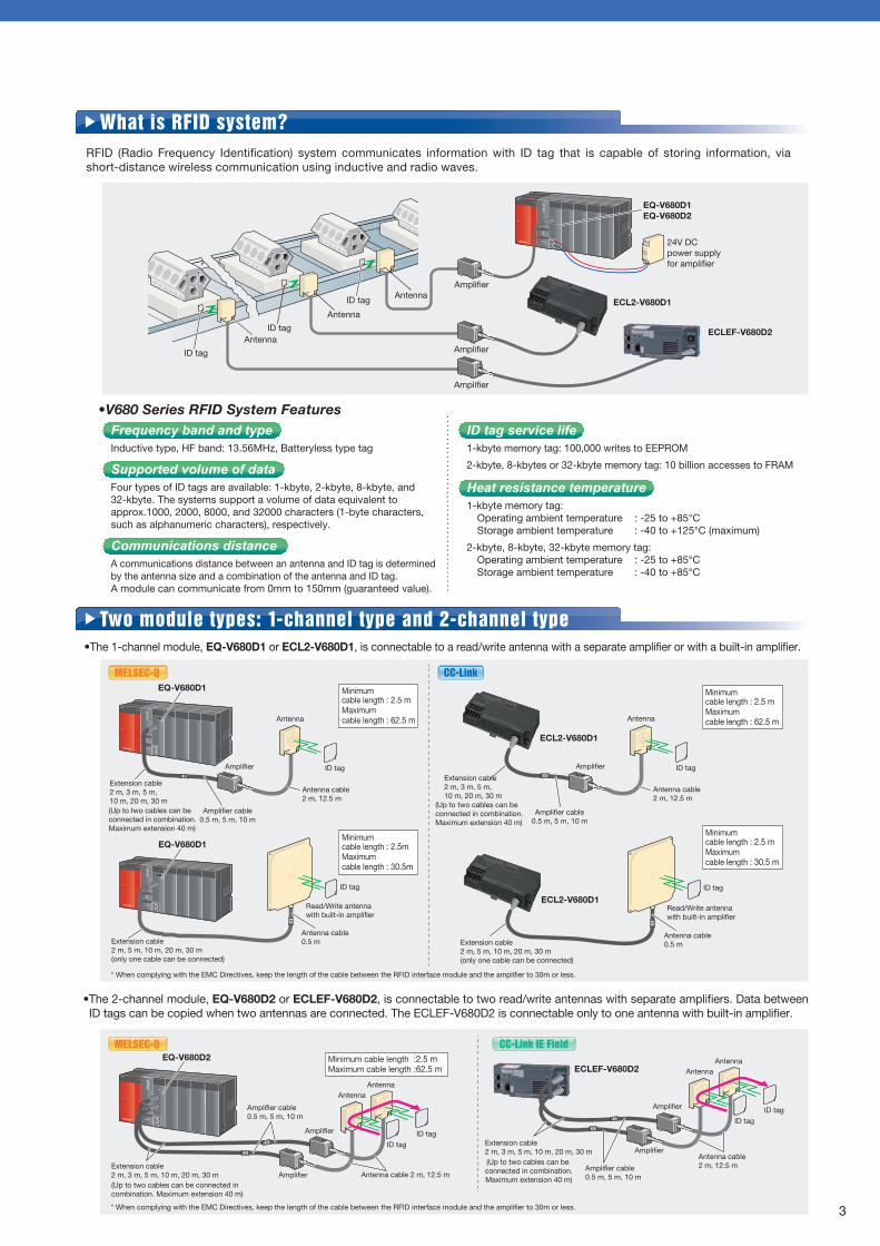
RFID (Radio Frequency Identification) system communicates information with ID tag that is capable of storing information, via short-distance wireless communication using inductive and radio waves.
Two module types: 1-channel type and 2-channel type•The 1-channel module, EQ-V680D1 or ECL2-V680D1, is connectable to a read/write antenna with a separate amplifier or with a built-in amplifier.
MODERUNERR
USERBAT
BOOT
USB
PULL
RS-232
•The 2-channel module, EQ-V680D2 or ECLEF-V680D2, is connectable to two read/write antennas with separate amplifiers. Data between ID tags can be copied when two antennas are connected. The ECLEF-V680D2 is connectable only to one antenna with built-in amplifier.
MODERUNERR
USERBAT
BOOT
USB
PULL
RS-232
Antenna
ID tagID tag
Antenna
Amplifier
EQ-V680D2
Amplifier Antenna cable 2 m, 12.5 m
Amplifier cable0.5 m, 5 m, 10 m
MODERUNERR
USERBAT
BOOT
USB
PULL
RS-232
MODERUNERR
USERBAT
BOOT
USB
PULL
RS-232
MODERUNERR
USERBAT
BOOT
USB
PULL
RS-232
EQ-V680D1EQ-V680D2
MODERUNERR
USERBAT
BOOT
USB
PULL
RS-232 24V DC power supply for amplifier
MODERUNERR
USERBAT
BOOT
USB
PULL
RS-232
EQ-V680D1
MODERUNERR
USERBAT
BOOT
USB
PULL
RS-232
MODERUNERR
USERBAT
BOOT
USB
PULL
RS-232
EQ-V680D1
Read/Write antennawith built-in amplifier
Antenna cable0.5 mExtension cable
2 m, 5 m, 10 m, 20 m, 30 m(only one cable can be connected)
ID tag
MODERUNERR
USERBAT
BOOT
USB
PULL
RS-232
ID tag
Antenna
Amplifier
Antenna cable2 m, 12.5 m
Amplifier cable0.5 m, 5 m, 10 m
What is RFID system?
Antenna
ID tag
ECL2-V680D1
Amplifier
Amplifier
Amplifier
MELSEC-Q
MELSEC-Q
CC-Link
Achieved high-speed communications with the MELSEC-Q series programmable controller CPU manufactured by Mitsubishi Electric Corporation
You can mount the RFID interface module directly to the MELSEC-Q series to enable high-speed communications with the programmable controller CPU.
Achieved distributed arrangement as the CC-Link remote device station
Using the RFID interface module as the CC-Link remote device station achieves connections with the RFID system V680 series manufactured by OMRON Corporation. The module can be placed at a distance of up to 1,200 m from the CC-Link master station.
Achieved distributed arrangement as the CC-Link IE Field intelligent device station
Using the RFID interface module as the CC-Link IE Field intelligent device station achieves connections with the RFID system V680 series manufactured by OMRON Corporation. The module can be placed at a distance of up to 12,000 m from the CC-Link IE Field master station.
1-channel and 2-channel modules
The 1-channel module, EQ-V680D1 is connectable to a read/write antenna with a separate amplifier or a read/write antenna with a built-in amplifier. The 2-channel module, EQ-V680D2, is connectable to two read/write antennas with separate amplifiers.
1-channel modules
The 1-channel module, ECL2-V680D1 is connectable to a read/write antenna with a separate amplifier or a read/write antenna with a built-in amplifier.
2-channel module
The 2-channel module, ECLEF-V680D2, is connectable to two antennas with separate amplifier or one antenna with a built-in amplifier.
Equipped with tests and measurement functions required for the start-up and maintenance
You can perform some diagnoses such as "tag communication test" and "distance level measurement"* between antennas and ID tags for start-up and maintenance.* CC-Link IE Field module is not supported.
iQSS (iQ Sensor Solution) reducing the time for development, debugging and start-up
Since the RFID interface module is compatible with Mitsubishi iQSS, on the screen of Mitsubishi MELSOFT GX Works2, you can easily perform the tests and measurement functions, including the "communications test" and the "distance level measurement".You can also check the module status (including the ON/OFF status of each signal and device values) to reduce the time for development, debugging, and start-up.
Function Block (FB) enabling the simple program development
We offer some programs such as the parameter settings or the programs for executing the function which includes date reading/writing as Function Block (FB).You can develop the programs easily by installing FB to your programs. You can download the FB library applicable to the Mitsubishi MELSOFT PLC Engineering Software from the MEEFAN or Mitsubishi Electric Factory Automation Website.
In regions other than Japan, please consult your local Mitsubishi representative.
Features
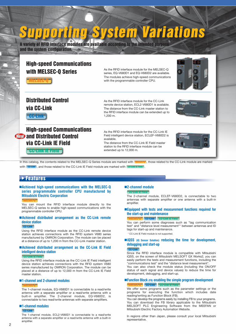
Supporting System VariationsSupporting System VariationsA variety of RFID interface modules are available according to the intended purpose and the system configuration.
High-speed Communications with MELSEC-Q Series
Distributed Control via CC-Link
In this catalog, the contents related to the MELSEC-Q Series module are marked with , those related to the CC-Link module are marked
with , and those related to the CC-Link IE Field module are marked with .CC-Link
MELSEC-Q
As the RFID interface module for the MELSEC-Q series, EQ-V680D1 and EQ-V680D2 are available.The modules achieve high-speed communications with the programmable controller CPU.
As the RFID interface module for the CC-Link remote device station, ECL2-V680D1 is available.The distance from the CC-Link master station to the RFID interface module can be extended up to 1,200 m.
High-speed Communications and Distributed Control via CC-Link IE Field
As the RFID interface module for the CC-Link IE Field intelligent device station, ECLEF-V680D2 is available.The distance from the CC-Link IE Field master station to the RFID interface module can be extended up to 12,000 m.
MELSEC-Q
MELSEC-Q
CC-Link
CC-Link
CC-Link
CC-Link
CC-Link
MELSEC-Q
2 3
CC-Link IE Field
CC-Link IE Field
CC-Link IE Field
CC-Link IE Field
MELSEC-Q CC-Link CC-Link IE Field
CC-Link IE Field
MELSEC-Q
CC-Link IE Field
ECLEF-V680D2
Antenna
Antenna
NewNew
ID tag
Extension cable2 m, 3 m, 5 m, 10 m, 20 m, 30 m(Up to two cables can be connected in combination.Maximum extension 40 m)
Extension cable2 m, 3 m, 5 m, 10 m, 20 m, 30 m(Up to two cables can be connected in combination. Maximum extension 40 m)
Extension cable2 m, 3 m, 5 m,10 m, 20 m, 30 m(Up to two cables can be connected in combination.Maximum extension 40 m)
ID tag service life1-kbyte memory tag: 100,000 writes to EEPROM
2-kbyte, 8-kbytes or 32-kbyte memory tag: 10 billion accesses to FRAM
Heat resistance temperature1-kbyte memory tag:
Operating ambient temperature : -25 to +85°CStorage ambient temperature : -40 to +125°C (maximum)
2-kbyte, 8-kbyte, 32-kbyte memory tag: Operating ambient temperature : -25 to +85°CStorage ambient temperature : -40 to +85°C
Frequency band and typeInductive type, HF band: 13.56MHz, Batteryless type tag
Supported volume of dataFour types of ID tags are available: 1-kbyte, 2-kbyte, 8-kbyte, and 32-kbyte. The systems support a volume of data equivalent to approx.1000, 2000, 8000, and 32000 characters (1-byte characters, such as alphanumeric characters), respectively.
Communications distanceA communications distance between an antenna and ID tag is determined by the antenna size and a combination of the antenna and ID tag. A module can communicate from 0mm to 150mm (guaranteed value).
Minimum cable length : 2.5 mMaximum cable length : 62.5 m
Minimumcable length : 2.5mMaximum cable length : 30.5m
(Up to two cables can be connected in combination.Maximum extension 40 m)
Minimum cable length : 2.5 mMaximum cable length : 62.5 m
Minimum cable length : 2.5 mMaximum cable length : 30.5 m
Minimum cable length :2.5 mMaximum cable length :62.5 m ECLEF-V680D2
Antenna
ID tagID tag
Antenna
Amplifier
Amplifier Antenna cable2 m, 12.5 mAmplifier cable
0.5 m, 5 m, 10 m
* When complying with the EMC Directives, keep the length of the cable between the RFID interface module and the amplifier to 30m or less.
* When complying with the EMC Directives, keep the length of the cable between the RFID interface module and the amplifier to 30m or less.
ECL2-V680D1
ECL2-V680D1
•V680 Series RFID System Features
ID tag
ID tag
Antenna
Amplifier
Read/Write antennawith built-in amplifier
Antenna cable0.5 m
Antenna cable2 m, 12.5 m
Amplifier cable0.5 m, 5 m, 10 m
ID tag
Extension cable2 m, 3 m, 5 m, 10 m, 20 m, 30 m
Extension cable2 m, 5 m, 10 m, 20 m, 30 m(only one cable can be connected)
RFID (Radio Frequency Identification) system communicates information with ID tag that is capable of storing information, via short-distance wireless communication using inductive and radio waves.
Two module types: 1-channel type and 2-channel type•The 1-channel module, EQ-V680D1 or ECL2-V680D1, is connectable to a read/write antenna with a separate amplifier or with a built-in amplifier.
MODERUNERR
USERBAT
BOOT
USB
PULL
RS-232
•The 2-channel module, EQ-V680D2 or ECLEF-V680D2, is connectable to two read/write antennas with separate amplifiers. Data between ID tags can be copied when two antennas are connected. The ECLEF-V680D2 is connectable only to one antenna with built-in amplifier.
MODERUNERR
USERBAT
BOOT
USB
PULL
RS-232
Antenna
ID tagID tag
Antenna
Amplifier
EQ-V680D2
Amplifier Antenna cable 2 m, 12.5 m
Amplifier cable0.5 m, 5 m, 10 m
MODERUNERR
USERBAT
BOOT
USB
PULL
RS-232
MODERUNERR
USERBAT
BOOT
USB
PULL
RS-232
MODERUNERR
USERBAT
BOOT
USB
PULL
RS-232
EQ-V680D1EQ-V680D2
MODERUNERR
USERBAT
BOOT
USB
PULL
RS-232 24V DC power supply for amplifier
MODERUNERR
USERBAT
BOOT
USB
PULL
RS-232
EQ-V680D1
MODERUNERR
USERBAT
BOOT
USB
PULL
RS-232
MODERUNERR
USERBAT
BOOT
USB
PULL
RS-232
EQ-V680D1
Read/Write antennawith built-in amplifier
Antenna cable0.5 mExtension cable
2 m, 5 m, 10 m, 20 m, 30 m(only one cable can be connected)
ID tag
MODERUNERR
USERBAT
BOOT
USB
PULL
RS-232
ID tag
Antenna
Amplifier
Antenna cable2 m, 12.5 m
Amplifier cable0.5 m, 5 m, 10 m
What is RFID system?
Antenna
ID tag
ECL2-V680D1
Amplifier
Amplifier
Amplifier
MELSEC-Q
MELSEC-Q
CC-Link
Achieved high-speed communications with the MELSEC-Q series programmable controller CPU manufactured by Mitsubishi Electric Corporation
You can mount the RFID interface module directly to the MELSEC-Q series to enable high-speed communications with the programmable controller CPU.
Achieved distributed arrangement as the CC-Link remote device station
Using the RFID interface module as the CC-Link remote device station achieves connections with the RFID system V680 series manufactured by OMRON Corporation. The module can be placed at a distance of up to 1,200 m from the CC-Link master station.
Achieved distributed arrangement as the CC-Link IE Field intelligent device station
Using the RFID interface module as the CC-Link IE Field intelligent device station achieves connections with the RFID system V680 series manufactured by OMRON Corporation. The module can be placed at a distance of up to 12,000 m from the CC-Link IE Field master station.
1-channel and 2-channel modules
The 1-channel module, EQ-V680D1 is connectable to a read/write antenna with a separate amplifier or a read/write antenna with a built-in amplifier. The 2-channel module, EQ-V680D2, is connectable to two read/write antennas with separate amplifiers.
1-channel modules
The 1-channel module, ECL2-V680D1 is connectable to a read/write antenna with a separate amplifier or a read/write antenna with a built-in amplifier.
2-channel module
The 2-channel module, ECLEF-V680D2, is connectable to two antennas with separate amplifier or one antenna with a built-in amplifier.
Equipped with tests and measurement functions required for the start-up and maintenance
You can perform some diagnoses such as "tag communication test" and "distance level measurement"* between antennas and ID tags for start-up and maintenance.* CC-Link IE Field module is not supported.
iQSS (iQ Sensor Solution) reducing the time for development, debugging and start-up
Since the RFID interface module is compatible with Mitsubishi iQSS, on the screen of Mitsubishi MELSOFT GX Works2, you can easily perform the tests and measurement functions, including the "communications test" and the "distance level measurement".You can also check the module status (including the ON/OFF status of each signal and device values) to reduce the time for development, debugging, and start-up.
Function Block (FB) enabling the simple program development
We offer some programs such as the parameter settings or the programs for executing the function which includes date reading/writing as Function Block (FB).You can develop the programs easily by installing FB to your programs. You can download the FB library applicable to the Mitsubishi MELSOFT PLC Engineering Software from the MEEFAN or Mitsubishi Electric Factory Automation Website.
In regions other than Japan, please consult your local Mitsubishi representative.
Features
Supporting System VariationsSupporting System VariationsA variety of RFID interface modules are available according to the intended purpose and the system configuration.
High-speed Communications with MELSEC-Q Series
Distributed Control via CC-Link
In this catalog, the contents related to the MELSEC-Q Series module are marked with , those related to the CC-Link module are marked
with , and those related to the CC-Link IE Field module are marked with .CC-Link
MELSEC-Q
As the RFID interface module for the MELSEC-Q series, EQ-V680D1 and EQ-V680D2 are available.The modules achieve high-speed communications with the programmable controller CPU.
As the RFID interface module for the CC-Link remote device station, ECL2-V680D1 is available.The distance from the CC-Link master station to the RFID interface module can be extended up to 1,200 m.
High-speed Communications and Distributed Control via CC-Link IE Field
As the RFID interface module for the CC-Link IE Field intelligent device station, ECLEF-V680D2 is available.The distance from the CC-Link IE Field master station to the RFID interface module can be extended up to 12,000 m.
MELSEC-Q
MELSEC-Q
CC-Link
CC-Link
CC-Link
CC-Link
CC-Link
MELSEC-Q
2 3
CC-Link IE Field
CC-Link IE Field
CC-Link IE Field
CC-Link IE Field
MELSEC-Q CC-Link CC-Link IE Field
CC-Link IE Field
MELSEC-Q
CC-Link IE Field
ECLEF-V680D2
Antenna
Antenna
NewNew
ID tag
Extension cable2 m, 3 m, 5 m, 10 m, 20 m, 30 m(Up to two cables can be connected in combination.Maximum extension 40 m)
Extension cable2 m, 3 m, 5 m, 10 m, 20 m, 30 m(Up to two cables can be connected in combination. Maximum extension 40 m)
Extension cable2 m, 3 m, 5 m,10 m, 20 m, 30 m(Up to two cables can be connected in combination.Maximum extension 40 m)
ID tag service life1-kbyte memory tag: 100,000 writes to EEPROM
2-kbyte, 8-kbytes or 32-kbyte memory tag: 10 billion accesses to FRAM
Heat resistance temperature1-kbyte memory tag:
Operating ambient temperature : -25 to +85°CStorage ambient temperature : -40 to +125°C (maximum)
2-kbyte, 8-kbyte, 32-kbyte memory tag: Operating ambient temperature : -25 to +85°CStorage ambient temperature : -40 to +85°C
Frequency band and typeInductive type, HF band: 13.56MHz, Batteryless type tag
Supported volume of dataFour types of ID tags are available: 1-kbyte, 2-kbyte, 8-kbyte, and 32-kbyte. The systems support a volume of data equivalent to approx.1000, 2000, 8000, and 32000 characters (1-byte characters, such as alphanumeric characters), respectively.
Communications distanceA communications distance between an antenna and ID tag is determined by the antenna size and a combination of the antenna and ID tag. A module can communicate from 0mm to 150mm (guaranteed value).
Minimum cable length : 2.5 mMaximum cable length : 62.5 m
Minimumcable length : 2.5mMaximum cable length : 30.5m
(Up to two cables can be connected in combination.Maximum extension 40 m)
Minimum cable length : 2.5 mMaximum cable length : 62.5 m
Minimum cable length : 2.5 mMaximum cable length : 30.5 m
Minimum cable length :2.5 mMaximum cable length :62.5 m ECLEF-V680D2
Antenna
ID tagID tag
Antenna
Amplifier
Amplifier Antenna cable2 m, 12.5 mAmplifier cable
0.5 m, 5 m, 10 m
* When complying with the EMC Directives, keep the length of the cable between the RFID interface module and the amplifier to 30m or less.
* When complying with the EMC Directives, keep the length of the cable between the RFID interface module and the amplifier to 30m or less.

4 5
Mitsubishi Electric CorporationMELSEC-Q series
programmable controller
Basic model QCPUHigh-performance model QCPU
Process CPUUniversal model QCPU
Master station
Master station
Mitsubishi Electric CorporationMELSEC-Q series
programmable controller
Basic model QCPUHigh-performance model QCPU
Process CPUUniversal model QCPU
Master station
2-kbyte
Model: V680-D2KF52M
Model: V680-D2KF52M-BT01
Model: V680-D2KF52M-BT11
Model: V680S-D2KF67MModel: V680S-D2KF67
Model: V680S-D2KF68MModel: V680S-D2KF68
8-kbyte
Model: V680-D8KF67MModel: V680-D8KF67
Model: V680S-D8KF67MModel: V680S-D8KF67
Model: V680-D8KF68Model: V680S-D8KF68MModel: V680S-D8KF68
32-kbyte
Model: V680-D32KF68
OMRON Corporation RFID System V680 Series
ID tag
1-kbyte
Model: V680-D1KP52MT
Model: V680-D1KP52M-BT01
Model: V680-D1KP52M-BT11
ECL2-V680D1
Remote device station
Model: V680-D1KP53M
Model: V680-D1KP66MTModel: V680-D1KP66T
Model: V680-D1KP54T
Model: V680-D1KP66T-SP
Model: V680-D1KP58HTN
Model: V680-H01-V2Cable length: 0.5 m
Extension cable
ECL2-V680D1
Remote device station
ECLEF-V680D2
Intelligent device station
EQ-V680D2
EQ-V680D1
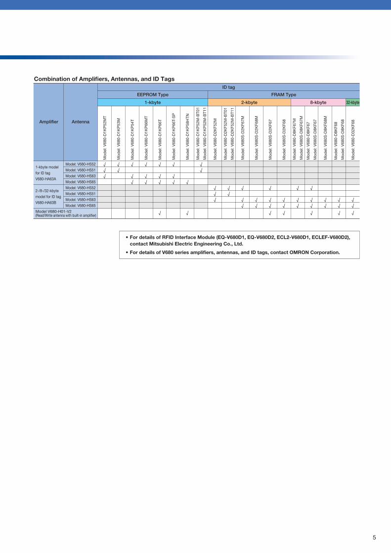
Combination of Amplifiers, Antennas, and ID Tags
Amplifier Antenna
ID tag
EEPROM Type FRAM Type
2-kbyte1-kbyte 8-kbyte 32-kbyte
√√√
√√
√
√√
√
√√
√
√
√√ √
√
√√
√√√
√√
√
√√
√√
√
√√
√
√√
√
√
√√
√
√√
√
√√
√
√√
√√
√
1-kbyte model
for ID tag
V680-HA63A
2-/8-/32-kbyte
model for ID tag
V680-HA63B
Model V680-H01-V2(Read/Write antenna with built-in amplifier)
Model: V680-HS52
Model: V680-HS51
Model: V680-HS63
Model: V680-HS65
Model: V680-HS52
Model: V680-HS51
Model: V680-HS63
Model: V680-HS65
√
√√
Mod
el: V
680-
D1K
P52
MT
Mod
el: V
680-
D1K
P53
M
Mod
el: V
680-
D1K
P54
T
Mod
el: V
680-
D1K
P66
MT
Mod
el: V
680-
D1K
P66
T
Mod
el: V
680-
D1K
P66
T-S
P
Mod
el: V
680-
D1K
P58
HTN
Mod
el: V
680-
D1K
P52
M-B
T01
Mod
el: V
680-
D1K
P52
M-B
T11
Mod
el: V
680-
D2K
F52M
Mod
el: V
680-
D2K
F52M
-BT0
1
Mod
el: V
680-
D2K
F52M
-BT1
1
Mod
el: V
680S
-D2K
F67M
Mod
el: V
680S
-D2K
F68M
Mod
el: V
680S
-D2K
F67
Mod
el: V
680S
-D2K
F68
Mod
el: V
680-
D8K
F67M
Mod
el: V
680S
-D8K
F67M
Mod
el: V
680-
D8K
F67
Mod
el: V
680S
-D8K
F67
Mod
el: V
680S
-D8K
F68M
Mod
el: V
680-
D8K
F68
Mod
el: V
680S
-D8K
F68
Mod
el: V
680-
D32
KF6
8
System configuration
Master station
EQ-V680D1
ECLEF-V680D2
Intelligent device station
Read/Write antenna
Model: V680-HS52
Model: V680-HS51
Model: V680-HS63
Model: V680-HS65Cable length:2 m/12.5 m
2-/8-/32-kbyteID tag amplifier
Model: V680-HA63BCable length:
0.5 m/5 m/10 m
1-kbyteID tag amplifier
Model: V680-HA63ACable length:
0.5 m/5 m/10 m
Extension cable
Extension cable
Model: V700-A40 2MCable length: 2 m
Model: V700-A41 3MCable length: 3 m
Model: V700-A42 5MCable length: 5 m
Model: V700-A43 10MCable length: 10 m
Model: V700-A44 20MCable length: 20 m
Model: V700-A45 30MCable length: 30 m
Model: V700-A40 2MCable length: 2 m
Model: V700-A41 3MCable length: 3 m
Model: V700-A42 5MCable length: 5 m
Model: V700-A43 10MCable length: 10 m
Model: V700-A44 20MCable length: 20 m
Model: V700-A45 30MCable length: 30 m
Model: V700-A40-W 2MCable length: 2 m
Model: V700-A40-W 5MCable length: 5 m
Model: V700-A40-W 10M Cable length: 10 m
Model: V700-A40-W 20MCable length: 20 m
Model: V700-A40-W 30MCable length: 30 m
* Only one antenna with built-in amplifier can be connected.
Read/Write antennawith built-in amplifier
If you need more information about OMRON Corporation products, please refer to the OMRON's catalog.
• For details of RFID Interface Module (EQ-V680D1, EQ-V680D2, ECL2-V680D1, ECLEF-V680D2), contact Mitsubishi Electric Engineering Co., Ltd.
• For details of V680 series amplifiers, antennas, and ID tags, contact OMRON Corporation.
* When complying with the EMC Directives, keep the length of the cable between the RFID interface module and the amplifier to 30m or less.
4 5
Mitsubishi Electric CorporationMELSEC-Q series
programmable controller
Basic model QCPUHigh-performance model QCPU
Process CPUUniversal model QCPU
Master station
Master station
Mitsubishi Electric CorporationMELSEC-Q series
programmable controller
Basic model QCPUHigh-performance model QCPU
Process CPUUniversal model QCPU
Master station
2-kbyte
Model: V680-D2KF52M
Model: V680-D2KF52M-BT01
Model: V680-D2KF52M-BT11
Model: V680S-D2KF67MModel: V680S-D2KF67
Model: V680S-D2KF68MModel: V680S-D2KF68
8-kbyte
Model: V680-D8KF67MModel: V680-D8KF67
Model: V680S-D8KF67MModel: V680S-D8KF67
Model: V680-D8KF68Model: V680S-D8KF68MModel: V680S-D8KF68
32-kbyte
Model: V680-D32KF68
OMRON Corporation RFID System V680 Series
ID tag
1-kbyte
Model: V680-D1KP52MT
Model: V680-D1KP52M-BT01
Model: V680-D1KP52M-BT11
ECL2-V680D1
Remote device station
Model: V680-D1KP53M
Model: V680-D1KP66MTModel: V680-D1KP66T
Model: V680-D1KP54T
Model: V680-D1KP66T-SP
Model: V680-D1KP58HTN
Model: V680-H01-V2Cable length: 0.5 m
Extension cable
ECL2-V680D1
Remote device station
ECLEF-V680D2
Intelligent device station
EQ-V680D2
EQ-V680D1
Combination of Amplifiers, Antennas, and ID Tags
Amplifier Antenna
ID tag
EEPROM Type FRAM Type
2-kbyte1-kbyte 8-kbyte 32-kbyte
√√√
√√
√
√√
√
√√
√
√
√√ √
√
√√
√√√
√√
√
√√
√√
√
√√
√
√√
√
√
√√
√
√√
√
√√
√
√√
√√
√
1-kbyte model
for ID tag
V680-HA63A
2-/8-/32-kbyte
model for ID tag
V680-HA63B
Model V680-H01-V2(Read/Write antenna with built-in amplifier)
Model: V680-HS52
Model: V680-HS51
Model: V680-HS63
Model: V680-HS65
Model: V680-HS52
Model: V680-HS51
Model: V680-HS63
Model: V680-HS65
√
√√
Mod
el: V
680-
D1K
P52
MT
Mod
el: V
680-
D1K
P53
M
Mod
el: V
680-
D1K
P54
T
Mod
el: V
680-
D1K
P66
MT
Mod
el: V
680-
D1K
P66
T
Mod
el: V
680-
D1K
P66
T-S
P
Mod
el: V
680-
D1K
P58
HTN
Mod
el: V
680-
D1K
P52
M-B
T01
Mod
el: V
680-
D1K
P52
M-B
T11
Mod
el: V
680-
D2K
F52M
Mod
el: V
680-
D2K
F52M
-BT0
1
Mod
el: V
680-
D2K
F52M
-BT1
1
Mod
el: V
680S
-D2K
F67M
Mod
el: V
680S
-D2K
F68M
Mod
el: V
680S
-D2K
F67
Mod
el: V
680S
-D2K
F68
Mod
el: V
680-
D8K
F67M
Mod
el: V
680S
-D8K
F67M
Mod
el: V
680-
D8K
F67
Mod
el: V
680S
-D8K
F67
Mod
el: V
680S
-D8K
F68M
Mod
el: V
680-
D8K
F68
Mod
el: V
680S
-D8K
F68
Mod
el: V
680-
D32
KF6
8
System configuration
Master station
EQ-V680D1
ECLEF-V680D2
Intelligent device station
Read/Write antenna
Model: V680-HS52
Model: V680-HS51
Model: V680-HS63
Model: V680-HS65Cable length:2 m/12.5 m
2-/8-/32-kbyteID tag amplifier
Model: V680-HA63BCable length:
0.5 m/5 m/10 m
1-kbyteID tag amplifier
Model: V680-HA63ACable length:
0.5 m/5 m/10 m
Extension cable
Extension cable
Model: V700-A40 2MCable length: 2 m
Model: V700-A41 3MCable length: 3 m
Model: V700-A42 5MCable length: 5 m
Model: V700-A43 10MCable length: 10 m
Model: V700-A44 20MCable length: 20 m
Model: V700-A45 30MCable length: 30 m
Model: V700-A40 2MCable length: 2 m
Model: V700-A41 3MCable length: 3 m
Model: V700-A42 5MCable length: 5 m
Model: V700-A43 10MCable length: 10 m
Model: V700-A44 20MCable length: 20 m
Model: V700-A45 30MCable length: 30 m
Model: V700-A40-W 2MCable length: 2 m
Model: V700-A40-W 5MCable length: 5 m
Model: V700-A40-W 10M Cable length: 10 m
Model: V700-A40-W 20MCable length: 20 m
Model: V700-A40-W 30MCable length: 30 m
* Only one antenna with built-in amplifier can be connected.
Read/Write antennawith built-in amplifier
If you need more information about OMRON Corporation products, please refer to the OMRON's catalog.
• For details of RFID Interface Module (EQ-V680D1, EQ-V680D2, ECL2-V680D1, ECLEF-V680D2), contact Mitsubishi Electric Engineering Co., Ltd.
• For details of V680 series amplifiers, antennas, and ID tags, contact OMRON Corporation.
* When complying with the EMC Directives, keep the length of the cable between the RFID interface module and the amplifier to 30m or less.

MELSEC-Q
MELSEC-Q
There are seven methods for communicating with ID tag. The communication method can be specified according to purpose.
With the trigger communication method, communication is performed with ID tag stopped inside an antenna communication area. Only one ID tag can exist inside a communications area.
With the repeat auto communication method, communication is performed upon automatic detection of a moving ID tag that has entered an antenna communications area. Communication is performed consecutively with ID tags that enter a communications area until the command execution request signal is turned OFF. Only one ID tag can exist inside a communications area.
With the auto communication method, communication is performed upon automatic detection of a moving ID tag that has entered an antenna communications area. Only one ID tag can exist inside a communication area.
With the FIFO repeat communication method, communication is performed upon automatic detection of a moving ID tag that has entered an antenna communications area. Communication is performed consecutively with ID tags that enter a communications area until the command execution request signal is turned OFF. This method can be used in cases where ID tags are close to each other. Only one operable ID tag can exist inside a communications area.
With the FIFO trigger communication method, communication is performed with an ID tag stopped inside an antenna communications area. This method can be used in cases where ID tags are close to each other. Only one operable ID tag can exist inside a communications area.
With the multi-access repeat communication method, communication is performed upon automatic detection of multiple moving ID tags that have entered an antenna communications area. Communication is performed consecutively with ID tags that enter the communications area until the command execution request signal is turned OFF.
With the multi-trigger communication method, communication is performed with multiple ID tags stopped inside an antenna communications area.
ID tag communication method
1) Trigger
2) Single auto
3) Repeat auto
4) FIFO trigger
5) FIFO repeat
6) Multi-access trigger
7) Multi-access repeat
MELSEC-Q CC-Link
ID tag BID tag C ID tag A
Communication area
ID tag B
ID tag C
ID tag A
Communication area
ID tag BID tag C ID tag A
Communication area
ID tag BID tag C ID tag A
Communication area
ID tag A
Communication area
ID tag AID tag B
Communication area
Communication is started by ID tag entering with the communication area.
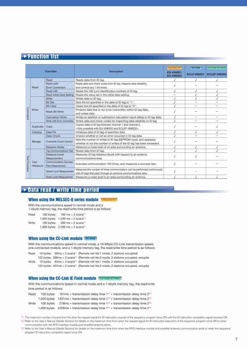
With the communications speed in normal mode and a 1-kbyte memory tag, the read/write time period is as follows:
Read 100 bytes: 169 ms + 2 scans*1
1,000 bytes: 1,339 ms + 2 scans*1
Write 100 bytes: 289 ms + 2 scans*1
1,000 bytes: 2,296 ms + 2 scans*1
When using the MELSEC-Q series module
With the communications speed in normal mode, a 10-Mbps CC-Link transmission speed, one connected module, and a 1-kbyte memory tag, the read/write time period is as follows:
Read 10 bytes: 59ms + 2 scans*1 (Remote net Ver.1 mode, 2 stations occupied) 122 bytes: 306ms + 2 scans*1 (Remote net Ver.2 mode, 2 stations occupied, octuple)Write 10 bytes: 93ms + 2 scans*1 (Remote net Ver.1 mode, 2 stations occupied) 122 bytes: 407ms + 2 scans*1 (Remote net Ver.2 mode, 2 stations occupied, octuple)
Read
Write
Duplicate
Initialize
Manage
Test/Measure
ReadRead with Error CorrectionRead UIDRead Initial Data SettingWriteBit SetBit Clear
Mask Bit Write
Calculation WriteWrite with Error Correction
Copy
Data FillData Check
Overwrite Count Control
Measure NoiseTag Communications TestDistance Level MeasurementCommunications Success Rate Measurement
Speed Level Measurement
Noise Level Measurement
Function
Reads data from ID tag.Reads data and check codes from ID tag, inspects data reliability, and corrects any 1-bit errors.Reads the UID (unit identification number) of ID tag.Reads the value set in the initial data setting.Writes data to ID tag.Sets the bit specified in the data of ID tag to "1".Clears the bit specified in the data of ID tag to "0".Protects data that is not to be overwritten within ID tag data, and writes data.Writes an addition or subtraction calculation result (data) to ID tag data.Writes data and check codes for inspecting data reliability to ID tag.Copies data of ID tag between channel 1 and channel 2.<Only possible with EQ-V680D2 and ECLEF-V680D2>Initializes data of ID tag of specified data.Checks whether or not an error occurred in ID tag data. Sets the number of writes to ID tag (EEPROM-type), and assesses whether or not the number of writes of the ID tag has been exceeded.Measures a noise level of an area surrounding an antenna.Reads data from ID tag.Measures ID tag distance (level) with respect to an antenna communications area.
Executes communication 100 times, and measures a success rate.
Measures the number of times communication can be performed continuously with ID tags that pass through an antenna communications area.Measures a noise level in an area surrounding an antenna.
√
√
√—√√√
√
√√
√
√√
√
√√
√
√
√
√
√
—
√√√——
—
——
—
√—
—
√√
√
—
—
√
DescriptionECL2-V680D1
√
—
√√√——
—
——
√
√—
—
√√
—
—
—
√
ECLEF-V680D2EQ-V680D1EQ-V680D2
Function list
Data read / write time period
When using the CC-Link module
With the communications speed in normal mode and a 1-kbyte memory tag, the read/write
time period is as follows:
Read 100 bytes: 161ms + transmission delay time 1*2 + transmission delay time 2*3
1,000 bytes: 1331ms + transmission delay time 1*2 + transmission delay time 2*3
Write 100 bytes: 278ms + transmission delay time 1*2 + transmission delay time 2*3
1,000 bytes: 2258ms + transmission delay time 1*2 + transmission delay time 2*3
When using the CC-Link IE Field module
*1: The maximum number of scans from the time the request signal for ID instruction request of the sequence program turns ON until the ID instruction completion signal receives ON.*2: Refer to the User’s Manual (Details Section) for details on the maximum time from when the request signal for ID instruction execution of the sequence program turns ON to when communication with the RFID interface module and amplifier/antenna starts.*3: Refer to the User’s Manual (Details Section) for details on the maximum time from when the RFID interface module and amplifier/antenna communication ends to when the sequence program ID instruction completion signal turns ON.
MELSEC-Q
CC-Link
MELSEC-Q CC-Link
CC-Link IE Field
CC-Link IE Field
CC-Link IE Field
MELSEC-Q CC-Link CC-Link IE Field
MELSEC-Q CC-Link CC-Link IE Field
MELSEC-Q CC-Link CC-Link IE Field
MELSEC-Q CC-Link CC-Link IE Field
6 7
Communication is started by ID tag entering with the communication area.
Communication is performed with ID tag existing inside a communications area when the command execution request signal turns ON.
ID tag with which communication is completed is set to an prohibited state.
Communication is started by ID tag entering with the communication area.
ID tag with which communi-cation is completed is set to an prohibited state.
Communication is performed with ID tags existing inside a communications area when the command execution request signal turns ON.
ID tag with which communication is completed is set to an prohibited state.
ID tag B
ID tag C
ID tag A
Communication area
Communication is performed with all ID tags that have entered a communications area.
ID tag with which communication is completed is set to an prohibited state.
Note) The FIFO trigger, FIFO repeat, multi-access trigger, and multi-access repeat methods are not available for the ID tags of V680-D1KP (EEPROM type).
Com
mand
Test Function
MELSEC-Q
MELSEC-Q
There are seven methods for communicating with ID tag. The communication method can be specified according to purpose.
With the trigger communication method, communication is performed with ID tag stopped inside an antenna communication area. Only one ID tag can exist inside a communications area.
With the repeat auto communication method, communication is performed upon automatic detection of a moving ID tag that has entered an antenna communications area. Communication is performed consecutively with ID tags that enter a communications area until the command execution request signal is turned OFF. Only one ID tag can exist inside a communications area.
With the auto communication method, communication is performed upon automatic detection of a moving ID tag that has entered an antenna communications area. Only one ID tag can exist inside a communication area.
With the FIFO repeat communication method, communication is performed upon automatic detection of a moving ID tag that has entered an antenna communications area. Communication is performed consecutively with ID tags that enter a communications area until the command execution request signal is turned OFF. This method can be used in cases where ID tags are close to each other. Only one operable ID tag can exist inside a communications area.
With the FIFO trigger communication method, communication is performed with an ID tag stopped inside an antenna communications area. This method can be used in cases where ID tags are close to each other. Only one operable ID tag can exist inside a communications area.
With the multi-access repeat communication method, communication is performed upon automatic detection of multiple moving ID tags that have entered an antenna communications area. Communication is performed consecutively with ID tags that enter the communications area until the command execution request signal is turned OFF.
With the multi-trigger communication method, communication is performed with multiple ID tags stopped inside an antenna communications area.
ID tag communication method
1) Trigger
2) Single auto
3) Repeat auto
4) FIFO trigger
5) FIFO repeat
6) Multi-access trigger
7) Multi-access repeat
MELSEC-Q CC-Link
ID tag BID tag C ID tag A
Communication area
ID tag B
ID tag C
ID tag A
Communication area
ID tag BID tag C ID tag A
Communication area
ID tag BID tag C ID tag A
Communication area
ID tag A
Communication area
ID tag AID tag B
Communication area
Communication is started by ID tag entering with the communication area.
With the communications speed in normal mode and a 1-kbyte memory tag, the read/write time period is as follows:
Read 100 bytes: 169 ms + 2 scans*1
1,000 bytes: 1,339 ms + 2 scans*1
Write 100 bytes: 289 ms + 2 scans*1
1,000 bytes: 2,296 ms + 2 scans*1
When using the MELSEC-Q series module
With the communications speed in normal mode, a 10-Mbps CC-Link transmission speed, one connected module, and a 1-kbyte memory tag, the read/write time period is as follows:
Read 10 bytes: 59ms + 2 scans*1 (Remote net Ver.1 mode, 2 stations occupied) 122 bytes: 306ms + 2 scans*1 (Remote net Ver.2 mode, 2 stations occupied, octuple)Write 10 bytes: 93ms + 2 scans*1 (Remote net Ver.1 mode, 2 stations occupied) 122 bytes: 407ms + 2 scans*1 (Remote net Ver.2 mode, 2 stations occupied, octuple)
Read
Write
Duplicate
Initialize
Manage
Test/Measure
ReadRead with Error CorrectionRead UIDRead Initial Data SettingWriteBit SetBit Clear
Mask Bit Write
Calculation WriteWrite with Error Correction
Copy
Data FillData Check
Overwrite Count Control
Measure NoiseTag Communications TestDistance Level MeasurementCommunications Success Rate Measurement
Speed Level Measurement
Noise Level Measurement
Function
Reads data from ID tag.Reads data and check codes from ID tag, inspects data reliability, and corrects any 1-bit errors.Reads the UID (unit identification number) of ID tag.Reads the value set in the initial data setting.Writes data to ID tag.Sets the bit specified in the data of ID tag to "1".Clears the bit specified in the data of ID tag to "0".Protects data that is not to be overwritten within ID tag data, and writes data.Writes an addition or subtraction calculation result (data) to ID tag data.Writes data and check codes for inspecting data reliability to ID tag.Copies data of ID tag between channel 1 and channel 2.<Only possible with EQ-V680D2 and ECLEF-V680D2>Initializes data of ID tag of specified data.Checks whether or not an error occurred in ID tag data. Sets the number of writes to ID tag (EEPROM-type), and assesses whether or not the number of writes of the ID tag has been exceeded.Measures a noise level of an area surrounding an antenna.Reads data from ID tag.Measures ID tag distance (level) with respect to an antenna communications area.
Executes communication 100 times, and measures a success rate.
Measures the number of times communication can be performed continuously with ID tags that pass through an antenna communications area.Measures a noise level in an area surrounding an antenna.
√
√
√—√√√
√
√√
√
√√
√
√√
√
√
√
√
√
—
√√√——
—
——
—
√—
—
√√
√
—
—
√
DescriptionECL2-V680D1
√
—
√√√——
—
——
√
√—
—
√√
—
—
—
√
ECLEF-V680D2EQ-V680D1EQ-V680D2
Function list
Data read / write time period
When using the CC-Link module
With the communications speed in normal mode and a 1-kbyte memory tag, the read/write
time period is as follows:
Read 100 bytes: 161ms + transmission delay time 1*2 + transmission delay time 2*3
1,000 bytes: 1331ms + transmission delay time 1*2 + transmission delay time 2*3
Write 100 bytes: 278ms + transmission delay time 1*2 + transmission delay time 2*3
1,000 bytes: 2258ms + transmission delay time 1*2 + transmission delay time 2*3
When using the CC-Link IE Field module
*1: The maximum number of scans from the time the request signal for ID instruction request of the sequence program turns ON until the ID instruction completion signal receives ON.*2: Refer to the User’s Manual (Details Section) for details on the maximum time from when the request signal for ID instruction execution of the sequence program turns ON to when communication with the RFID interface module and amplifier/antenna starts.*3: Refer to the User’s Manual (Details Section) for details on the maximum time from when the RFID interface module and amplifier/antenna communication ends to when the sequence program ID instruction completion signal turns ON.
MELSEC-Q
CC-Link
MELSEC-Q CC-Link
CC-Link IE Field
CC-Link IE Field
CC-Link IE Field
MELSEC-Q CC-Link CC-Link IE Field
MELSEC-Q CC-Link CC-Link IE Field
MELSEC-Q CC-Link CC-Link IE Field
MELSEC-Q CC-Link CC-Link IE Field
6 7
Communication is started by ID tag entering with the communication area.
Communication is performed with ID tag existing inside a communications area when the command execution request signal turns ON.
ID tag with which communication is completed is set to an prohibited state.
Communication is started by ID tag entering with the communication area.
ID tag with which communi-cation is completed is set to an prohibited state.
Communication is performed with ID tags existing inside a communications area when the command execution request signal turns ON.
ID tag with which communication is completed is set to an prohibited state.
ID tag B
ID tag C
ID tag A
Communication area
Communication is performed with all ID tags that have entered a communications area.
ID tag with which communication is completed is set to an prohibited state.
Note) The FIFO trigger, FIFO repeat, multi-access trigger, and multi-access repeat methods are not available for the ID tags of V680-D1KP (EEPROM type).
Com
mand
Test Function
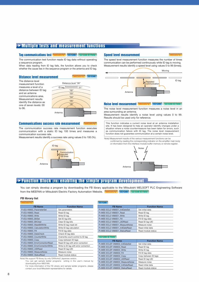
Communications success rate measurementThe communication success rate measurement function executes communication with a static ID tag 100 times and measures a communication success rate. Measurement results identify a success rate using values 0 to 100 (%).
Tag communications testThe communication test function reads ID tag data without operating a sequence program. When data reading from ID tag fails, the function allows you to check whether the cause lies in the sequence program or the antenna and ID tag.
Distance level measurementThe distance level measurement function measures a level of a distance between ID tag and an antenna communications area. Measurement results identify the distance as one of seven levels: 00 to 06.
MELSEC-Q CC-Link
MELSEC-Q
MELSEC-Q
This function indicates a current noise level at an antenna installation site. It has been designed to help an operator identify changes under a situation where a noise countermeasure has been taken for errors, such as communication failure with ID tag. The noise level measurement function does not guarantee communication at a certain noise level.
Note) Measurement results of the various measurement functions can be confirmed by reading the corresponding indicator on the amplifier main body or information from the interface module buffer memory or remote register.
Speed level measurementThe speed level measurement function measures the number of times communication can be performed continuously while ID tag is moving. Measurement results identify a speed level using values 0 to 99 (times).
Noise level measurementThe noise level measurement function measures a noise level in an area surrounding an antenna. Measurement results identify a noise level using values 0 to 99. Results should be used only for reference.
Easy start-upWhen you start up or modify the system, the RFID interface module detects the slave stations connected to the CC-Link master/local modules in the actual system configuration, and reflects the detected data to the CC-Link configuration window on the PLC Engineering Software.In this window, you can easily perform the "communi-cations test", the "distance level measurement", or others.
Sensor monitorThe status of the iQSS (iQ Sensor Solution) -compat-ible equipment connected to the CC-Link master/local modules appears in the monitor information window of the PLC Engineering Software.In this window, you can easily check the status of the module (including the ON/OFF status of each signal and device values).
Note) We support the function of iQSS by only GXWorks2 Japanese version.
Easy programmingYou can import the label information of ECL2-V680D1 to the user program and specify the device number using the label name. This enables you to create an easy-to-understand program.
Multiple tests and measurement functionsThe CC-Link RFID interface module, ECL2-V680D1, is compatible with Mitsubishi iQSS to achieve the easy start-up, monitoring, and programming of the RFID system.
Compatible with iQSS (iQ Sensor Solution)
CC-Link
You can simply develop a program by downloading the FB library applicable to the Mitsubishi MELSOFT PLC Engineering Software
from the MEEFAN or Mitsubishi Electric Factory Automation Website.
FB library list
P+EQ-V680D_ParameterSet
P+EQ-V680D_Read
P+EQ-V680D_Write
P+EQ-V680D_BitSet
P+EQ-V680D_BitClear
P+EQ-V680D_MaskBitWrite
P+EQ-V680D_CalculationWrite
P+EQ-V680D_Fill
P+EQ-V680D_DataCheck
P+EQ-V680D_CounterWrite
P+EQ-V680D_Copy
P+EQ-V680D_ErrorCorrectionRead
P+EQ-V680D_ErrorCorrectionWrite
P+EQ-V680D_UIDRead
P+EQ-V680D_MeasureNoise
P+EQ-V680D_StatusRead
FB NameSet parameters
Read ID tag
Write ID tag
Set ID tag bits
Clear ID tag bits
Write ID tag mask bit
Write ID tag calculation
Fill ID tag data
Check ID tag data
Overwrite count control to ID tag
Copy between ID tags
Read ID tag with error correction
Write to ID tag with error correction
Read ID tag UID
Measure noise
Read module status
Function Nama
Function Block (FB) enabling the simple program development
P+MEE-ECL2-V680D1_InitDateSet
P+MEE-ECL2-V680D1_Read
P+MEE-ECL2-V680D1_Write
P+MEE-ECL2-V680D1_Fill
P+MEE-ECL2-V680D1_UIDRead
P+MEE-ECL2-V680D1_MeasureNoise
P+MEE-ECL2-V680D1_InitDateRead
P+MEE-ECL2-V680D1_StatusRead
FB NameSet initial data
Read ID tag
Write ID tag
Fill ID tag data
Read ID tag UID
Measure noise
Read initial data
Read module status
Function Nama
P+MEE-ECLEF-V680D2_InitDateSet
P+MEE-ECLEF-V680D2_Read
P+MEE-ECLEF-V680D2_Write
P+MEE-ECLEF-V680D2_Fill
P+MEE-ECLEF-V680D2_Copy
P+MEE-ECLEF-V680D2_UIDRead
P+MEE-ECLEF-V680D2_MeasureNoise
P+MEE-ECLEF-V680D2_InitDateRead
P+MEE-ECLEF-V680D2_StatusRead
FB NameSet initial data
Read ID tag
Write ID tag
Fill ID tag data
Copy between ID tags
Read ID tag UID
Measure noise
Read initial data
Read module status
Function Nama
MELSEC-Q CC-Link
MELSEC-Q CC-Link
CC-Link IE Field
8 9
CC-Link IE Field
CC-Link IE Field
MELSEC-Q CC-Link
MELSEC-Q CC-Link CC-Link IE Field
Antenna
Distance level "00"
ID tag"02"
"01"
"03"
"04"
"05"
"06"
ID tag
Antenna
Communicationexecuted 100 times
Antenna
Moving
Repeatedcommunication
ID tag
Noise
Antenna
Note) We support FB library by only GXWorks2 Japanese version.You can get sample ladder programs writing in the user's manual by downloading from MEEFAN.For more information of the FB Library and sample ladder programs, please contact your local Mitsubishi representative for details.
Graphically displaying the CC-Link network configuration
Equipment configuration diagram
Displaying the ON/OFF status of the remote I/O signals and the remote device values in ECL2-V680D1
Import the label name of the sensor!
Utilize the label name!

Number of connectable antennas
CC-Link side
Power supply
Weight
Outer dimensions
Station type
Version
Station number selection
Transmission speed
Number of
occupied stations
and data transfer size
Connection cable
Item
1
Remote device station
Version 1.10 and Version 2.0
For 2 stations occupied: Station numbers 1 to 63 For 4 stations occupied: Station numbers 1 to 61
156 kbps/625 kbps/2.5 Mbps/5 Mbps/10 Mbps (Selectable)
Ver.1.10-compatible CC-Link dedicated cable
CC-Link dedicated cable (Ver.1.00-compatible)
CC-Link dedicated high-performance cable (Ver.1.00-compatible)
20.4 to 26.4 V DC (24 V DC -15%, +10%) (Ripple ratio: within 5%)
Current consumption: 0.33 A or less
0.3 kg
65 (H) x 150(W) x 45 (D) mm (for module unit excluding connected antenna cable)
ECL2-V680D1
Specifications
1-channel RFID interface module
ECL2-V680D1 RFID Interface Module
User's Manual
ECL2-V680D1 RFID Interface Module
User's Manual [English version]
Product Name
ECL2-V680D1
ECL2-V680D1-MAN-JP
ECL2-V680D1-MAN-E
•ECL2-V680D1 (main unit)
•User's Manual (Hardware)
ECL2-V680D1 RFID Interface Module Specifications
/ Programming Method Descriptions
Product Name Remarks
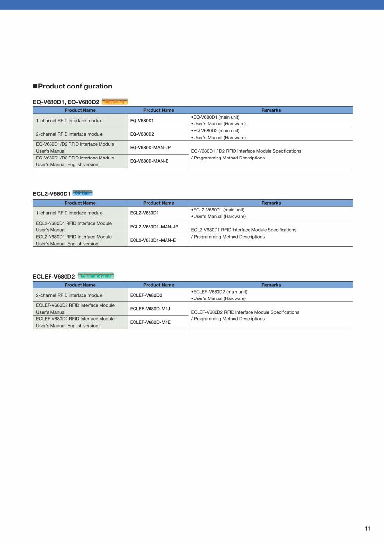
ECL2-V680D1
ECL2-V680D1
2-channel RFID interface module
ECLEF-V680D2 RFID Interface Module
User's Manual
ECLEF-V680D2 RFID Interface Module
User's Manual [English version]
Product Name
ECLEF-V680D2
ECLEF-V680D-M1J
ECLEF-V680D-M1E
•ECLEF-V680D2 (main unit)
•User's Manual (Hardware)
ECLEF-V680D2 RFID Interface Module Specifications
/ Programming Method Descriptions
Product Name Remarks
ECLEF-V680D2
1-channel RFID interface module
2-channel RFID interface module
EQ-V680D1/D2 RFID Interface Module
User's Manual
EQ-V680D1/D2 RFID Interface Module
User's Manual [English version]
Product Name
EQ-V680D1
EQ-V680D2
EQ-V680D-MAN-JP
EQ-V680D-MAN-E
•EQ-V680D1 (main unit)
•User's Manual (Hardware)
•EQ-V680D2 (main unit)
•User's Manual (Hardware)
EQ-V680D1 / D2 RFID Interface Module Specifications
/ Programming Method Descriptions
Product Name Remarks
EQ-V680D1, EQ-V680D2
Product configuration
EQ-V680D1, EQ-V680D2
Performance specifications
Number of connectable antennas
Data transfer volume
(number of communicated data bytes per a transfer)
Number of occupied IO points
5 V DC internal power supply current consumption
24 V DC external power supply current consumption
(20.4 to 26.4 V DC)
Recommended 24 V DC power supply
Weight
Outer dimensions
Item
2048 bytes, maximum
32 points (IO assignments: 32 intelligent module points)
S8VS-03024 (Manufuctured by OMRON Corporation)
98 (H) x 27.4 (W) x 106.5 (D) mm (for module unit excluding connected antenna cable)
2
0.52 A
0.37 A
0.2 kg
1
0.42 A
0.25 A
0.2 kg
EQ-V680D2EQ-V680D1
Specifications
CC-Link version
Version 1.10
Version 2.0
Number of
occupied stations
2 stations occupied
4 stations occupied
2 stations occupied
Extended
cyclic settings
Double
Quadruple
Octuple
Data transfer size
8 words
16 words
16 words
32 words
64 words
Writable/readable data size
per ID instruction
10 bytes
26 bytes
26 bytes
58 bytes
122 bytes
Number of connectable antennas
CC-Link IE Field
side
Power supply
Weight
Outer dimensions
Station type
Station number selection
Network number
Communication speed
Data transmission volume
Connection cable
Item
2
Intelligent device station
1 to 120
1 to 239
1 Gbps
Data volume writable/readable with one ID command
8 to 1016 bytes (variable), set with parameters
1000BASE-T Standard compliant Ethernet cable
Category 5e or higher (with double shield, STP), straight cable
20.4 to 28.8 V DC (24 V DC -15%, +20%) (Ripple ratio: within 5%)
Current consumption: 0.60 A
0.3 kg
55 (H) x 180(W) x 70 (D) mm (for module unit excluding connected antenna cable)
ECLEF-V680D2
Specifications
ECLEF-V680D2
10 11
MELSEC-Q MELSEC-Q
CC-Link
CC-Link
CC-Link IE Field
CC-Link IE Field
Number of connectable antennas
CC-Link side
Power supply
Weight
Outer dimensions
Station type
Version
Station number selection
Transmission speed
Number of
occupied stations
and data transfer size
Connection cable
Item
1
Remote device station
Version 1.10 and Version 2.0
For 2 stations occupied: Station numbers 1 to 63 For 4 stations occupied: Station numbers 1 to 61
156 kbps/625 kbps/2.5 Mbps/5 Mbps/10 Mbps (Selectable)
Ver.1.10-compatible CC-Link dedicated cable
CC-Link dedicated cable (Ver.1.00-compatible)
CC-Link dedicated high-performance cable (Ver.1.00-compatible)
20.4 to 26.4 V DC (24 V DC -15%, +10%) (Ripple ratio: within 5%)
Current consumption: 0.33 A or less
0.3 kg
65 (H) x 150(W) x 45 (D) mm (for module unit excluding connected antenna cable)
ECL2-V680D1
Specifications
1-channel RFID interface module
ECL2-V680D1 RFID Interface Module
User's Manual
ECL2-V680D1 RFID Interface Module
User's Manual [English version]
Product Name
ECL2-V680D1
ECL2-V680D1-MAN-JP
ECL2-V680D1-MAN-E
•ECL2-V680D1 (main unit)
•User's Manual (Hardware)
ECL2-V680D1 RFID Interface Module Specifications
/ Programming Method Descriptions
Product Name Remarks
ECL2-V680D1
ECL2-V680D1
2-channel RFID interface module
ECLEF-V680D2 RFID Interface Module
User's Manual
ECLEF-V680D2 RFID Interface Module
User's Manual [English version]
Product Name
ECLEF-V680D2
ECLEF-V680D-M1J
ECLEF-V680D-M1E
•ECLEF-V680D2 (main unit)
•User's Manual (Hardware)
ECLEF-V680D2 RFID Interface Module Specifications
/ Programming Method Descriptions
Product Name Remarks
ECLEF-V680D2
1-channel RFID interface module
2-channel RFID interface module
EQ-V680D1/D2 RFID Interface Module
User's Manual
EQ-V680D1/D2 RFID Interface Module
User's Manual [English version]
Product Name
EQ-V680D1
EQ-V680D2
EQ-V680D-MAN-JP
EQ-V680D-MAN-E
•EQ-V680D1 (main unit)
•User's Manual (Hardware)
•EQ-V680D2 (main unit)
•User's Manual (Hardware)
EQ-V680D1 / D2 RFID Interface Module Specifications
/ Programming Method Descriptions
Product Name Remarks
EQ-V680D1, EQ-V680D2
Product configuration
EQ-V680D1, EQ-V680D2
Performance specifications
Number of connectable antennas
Data transfer volume
(number of communicated data bytes per a transfer)
Number of occupied IO points
5 V DC internal power supply current consumption
24 V DC external power supply current consumption
(20.4 to 26.4 V DC)
Recommended 24 V DC power supply
Weight
Outer dimensions
Item
2048 bytes, maximum
32 points (IO assignments: 32 intelligent module points)
S8VS-03024 (Manufuctured by OMRON Corporation)
98 (H) x 27.4 (W) x 106.5 (D) mm (for module unit excluding connected antenna cable)
2
0.52 A
0.37 A
0.2 kg
1
0.42 A
0.25 A
0.2 kg
EQ-V680D2EQ-V680D1
Specifications
CC-Link version
Version 1.10
Version 2.0
Number of
occupied stations
2 stations occupied
4 stations occupied
2 stations occupied
Extended
cyclic settings
Double
Quadruple
Octuple
Data transfer size
8 words
16 words
16 words
32 words
64 words
Writable/readable data size
per ID instruction
10 bytes
26 bytes
26 bytes
58 bytes
122 bytes
Number of connectable antennas
CC-Link IE Field
side
Power supply
Weight
Outer dimensions
Station type
Station number selection
Network number
Communication speed
Data transmission volume
Connection cable
Item
2
Intelligent device station
1 to 120
1 to 239
1 Gbps
Data volume writable/readable with one ID command
8 to 1016 bytes (variable), set with parameters
1000BASE-T Standard compliant Ethernet cable
Category 5e or higher (with double shield, STP), straight cable
20.4 to 28.8 V DC (24 V DC -15%, +20%) (Ripple ratio: within 5%)
Current consumption: 0.60 A
0.3 kg
55 (H) x 180(W) x 70 (D) mm (for module unit excluding connected antenna cable)
ECLEF-V680D2
Specifications
ECLEF-V680D2
10 11
MELSEC-Q MELSEC-Q
CC-Link
CC-Link
CC-Link IE Field
CC-Link IE Field

NewNew
RFID Interface Module for OMRON RFID System V680 Series
ID tag
Antenna
Amplifier
Read/Write antennawith built-in amplifier
MELSEC-Q seriesprogrammable controller
manufactured byMitsubishi Electric Corporation
EQ-V680D1
ECL2-V680D1
EQ-V680D2 RFID system V680 seriesmanufactured by OMRON Corporation
CC-Link remote device stationCC-Link master station
ECLEF-V680D2
CC-Link IE Field intelligent device stationCC-Link IE Field master station
RFID interface module for MELSEC-Q series
RFID interface module for CC-Link
RFID interface module for CC-Link IE Field
MELSEC-Q SeriesModel: EQ-V680D1 1-Channel RFID Interface ModuleModel: EQ-V680D2 2-Channel RFID Interface Module
CC-Link Remote DeviceModel: ECL2-V680D1 1-Channel RFID Interface Module
CC-Link IE Field Intelligent DeviceModel: ECLEF-V680D2 2-Channel RFID Interface Module
Connecting the MELSEC-Q Series/CC-Link/CC-Link IE Field
System and the RFID System V680 Series!OMRON Corporation
Mitsubishi Electric Corporation
CC-Link master module manufactured by Mitsubishi Electric Corporation
CC-Link IE Field master modulemanufactured by
Mitsubishi Electric Corporation
1-13-5, Kudankita, Chiyoda-ku, Tokyo, 102-0073, Japan URL:http://www.mee.co.jp/
This catalog explains the typical features and functions of the MELSEC-Q Series EQ-V680D1 1-channel RFID Interface Module, EQ-V680D2 2-channel RFID Interface Module, CC-Link ECL2-V680D1 1-channel RFID Interface Module, and CC-Link IE Field ECLEF-V680D2 2-channel RFID Interface Module. Restrictions and other information on usage and module combinations are not provided. When using the products, always read the user's manuals of the products. Mutsubushi Electric Engineering will not be held liable for damage caused by factors found not to be the cause of Mutsubushi Electric Engineering; machine damage or lost profits caused by faults in the Mutsubushi Electric Engineering products; damage, secondary damage, accident compensation caused by special factors unpredictable by Mutsubushi Electric Engineering; damages to products other than Mutsubushi Electric Engineering products; and to other duties.
Precautions for Choosing the ProductsThis product has been manufactured as a general-purpose part for general industries, and has not been designed or manufactured to be incorporated in a device or system used in purposes related to human life. Before using the product for special purposes such as nuclear power, electric power, aerospace, medicine or passenger movement vehicles, consult with Mitsubishi.This product has been manufactured under strict quality control. However, when installing the product where major accidents or losses could occur if the product fails, install appropriate backup or failsafe functions in the system.
For safe operations
New publication,effective Jan. 2016Specifications subject to change without notice.MEI C099E •148B (1601)MEE
All company and product names herein are eiter trademarks or registered tarademarks of their respective owners.