connecting sew brakes to distributed siemens converters · connecting sew brakes to distributed...
TRANSCRIPT

Applications & Tools
Answers for industry.
Cover sheet
Connecting SEW brakes to distributed Siemens converters As an example connected to SINAMICS G120D
Application description September 2012

2 Connecting SEW brakes to distributed Siemens converters
1.0, Entry ID: 63969856
Co
pyr
igh
t
Sie
me
ns
AG
20
12
All
righ
ts r
ese
rve
d
Siemens Industry Online Support
This article comes from the Siemens Industry Online Support. You can go directly to the download page of this document using the following link:
http://support.automation.siemens.com/WW/view/en/63969856
Caution: The functions and solutions described in this document predominantly address the implementation of the automation task. Please note, that when networking your plant with other plant parts, the company network or the Internet, the appropriate protective measures must be taken regarding industrial security. You can find additional information under entry ID 50203404.
http://support.automation.siemens.com/WW/view/en/50203404
Please also actively use our technical forum in the Siemens Industry Online Support on this topic. Send in your questions, suggestions or problems, and discuss these with our strong forum community:
http://www.siemens.de/forum-applikationen

Connecting SEW brakes to distributed Siemens converters 1.0, Entry ID: 63969856 3
Co
pyr
igh
t
Sie
me
ns
AG
20
12
All
righ
ts r
ese
rve
d
s
SINAMICS G120D Connecting SEW brakes to distributed Siemens converters
Task
1
Solution
2
Basic
3
Hardware connections
4
Commissioning the brake
5 Comparison of the control modes
6
References
7
Contact person
8
History
9

Table of contents
4 Connecting SEW brakes to distributed Siemens converters
1.0, Entry ID: 63969856
Co
pyr
igh
t
Sie
me
ns
AG
20
12
All
righ
ts r
ese
rve
d
Warranty and liability Note The application examples are not binding and do not claim to be complete
regarding the configuration and equipping as well as possible eventualities. The application examples do not represent customer-specific solutions. They are only intended to provide support for typical applications. You are responsible in ensuring that the described products are correctly used. These application examples do not relieve you of the responsibility of safely and professionally using, installing, operating and servicing equipment. When using these application examples, you recognize that we cannot be made liable for any damage/claims beyond the liability clause described. We reserve the right to make changes to these application examples at any time without prior notice. If there are any deviations between the recommendations provided in this application example and other Siemens publications - e.g. Catalogs, then the contents of the other documents have priority.
We do not accept any liability for the information contained in this document.
Claims against us – irrespective of the legal grounds – resulting from the use of the examples described in this application example, information, programs, engineering and performance data etc. are excluded. Such an exclusion shall not apply where liability is mandatory, e.g. under the German Product Liability Act involving intent, gross negligence, or injury of life, body or health, guarantee for the quality of a product, fraudulent concealment of a deficiency or non-performance. Claims of the purchaser for compensation relating to non-performance of essential contract obligations shall be limited to foreseeable damages typically covered by a contract unless intent, willful misconduct or gross negligence is involved or injury of life, body or health. The above stipulations shall not change the burden of proof to your detriment.
It is not permissible to transfer or copy these application examples or excerpts of them without first having prior authorization from Siemens Industry Sector in writing.

Table of contents
Connecting SEW brakes to distributed Siemens converters 1.0, Entry ID: 63969856 5
Co
pyr
igh
t
Sie
me
ns
AG
20
12
All
righ
ts r
ese
rve
d
Table of contents Warranty and liability................................................................................................... 4 1 Task..................................................................................................................... 6
1.1 Overview .............................................................................................. 6 2 Solution............................................................................................................... 7
2.1 Basic solution 1 – direct connection..................................................... 7 2.2 Basic solution 2 – external brake control ............................................. 8 2.3 Possible hardware and software components ..................................... 9
3 Basics ............................................................................................................... 11 3.1 Basics on the SEW brake .................................................................. 11 3.2 Brake output at the G120D ................................................................ 12
4 Hardware connections .................................................................................... 13 4.1 Pin assignment of the G120D ............................................................ 13 4.2 Motor cable pin assignment for ECOFAST plug HAN 10E................ 15
5 Commissioning the brake............................................................................... 16 5.1 Basic commissioning of the drive....................................................... 16 5.2 Configuration screen form brake control ............................................ 16 5.3 Release brake screen form ................................................................ 18 5.4 Close brake screen form .................................................................... 19
6 Comparison of the control modes ................................................................. 20 6.1 Measuring technique.......................................................................... 20 6.2 Releasing ........................................................................................... 21 6.3 In the released state........................................................................... 22 6.4 Closing ............................................................................................... 23
7 References ....................................................................................................... 24 7.1 Internet links - data............................................................................. 24
8 Contact person ................................................................................................ 24 9 History............................................................................................................... 24

1 Task
6 Connecting SEW brakes to distributed Siemens converters
1.0, Entry ID: 63969856
Co
pyr
igh
t
Sie
me
ns
AG
20
12
All
righ
ts r
ese
rve
d
1 Task
1.1 Overview
Introduction
A distributed Siemens converter is to be connected to a SEW motor equipped with brake.
However, the converter power unit has an integrated brake rectification circuit. Which is available via two connections (brake + and brake -).
However, the SEW motor has a brake that has 3 connections.
As a consequence, the question arises how these two different systems can be connected with one another.
Overview of the task
Figure 1-1
Task description
The task of the application is to open the SEW brake from the SINAMICS G120D, without requiring additional functions in the PLC.

2 Solution
Connecting SEW brakes to distributed Siemens converters 1.0, Entry ID: 63969856 7
Co
pyr
igh
t
Sie
me
ns
AG
20
12
All
righ
ts r
ese
rve
d
2 Solution There are two principle solutions. These will be explained based on the SINAMICS G120D. Alternatively, the G110D and the ET200proFC can also be used. Although these have the same connections, they differ however in the commissioning screen forms as well as the direct connection when opening (boost function of the G110D) and closing the brakes (no accelerated voltage reduction/decay).
2.1 Basic solution 1 – direct connection
Schematic
Figure 2-1
*For the pin assignment of the Siemens components, see Chapter 4 Hardware connections
The brake connection of the G120D is directly connected to the SEW brake using an auxiliary terminal strip. The center connection of the brake solenoid must be isolated.
Advantages
• Low hardware costs
• The brake is controlled with low delay
• Fewer error sources
Disadvantages
• Accelerator solenoid of the brake is not used.

2 Solution
8 Connecting SEW brakes to distributed Siemens converters
1.0, Entry ID: 63969856
Co
pyr
igh
t
Sie
me
ns
AG
20
12
All
righ
ts r
ese
rve
d
• Only suitable for SEW brakes that are dimensioned for the supply voltage of the G120D. UDC = ULINE * 0.45
2.2 Basic solution 2 – external brake control
Schematic
Figure 2-2
*For the pin assignment of the Siemens components, see Chapter 4 Hardware connections
The SEW brake is connected via a contactor, which is controlled from a G120D digital output.
In this case, a distinction can be made between shutdown on the AC side and shutdown on the DC and AC sides (see Fig. 3-1).
When opening, both control types behave in the same way. However, when closing, shutdown on the DC side means that the current flowing through the solenoid is more quickly reduced to zero. This results in a shorter closing time.
For a shutdown on the AC side only, the connection between contacts 4 and 5 via the contactor is eliminated, and the blue cable is directly connected to 5.
Advantages
• The acceleration circuit is used
• Alternatively, it can also be used for braking with different input voltages
Disadvantages
• High wiring costs
• Many components
• Additional delay when controlling the brake
2 Solution
Connecting SEW brakes to distributed Siemens converters 1.0, Entry ID: 63969856 9
Co
pyr
igh
t
Sie
me
ns
AG
20
12
All
righ
ts r
ese
rve
d
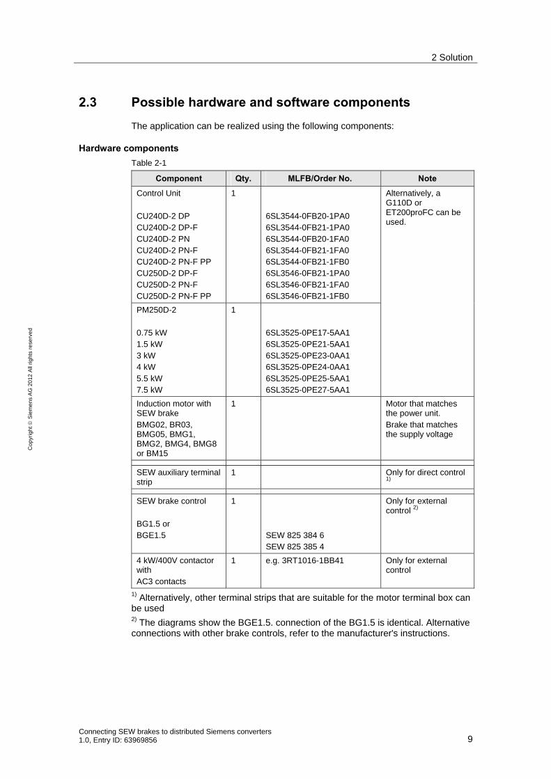
2.3 Possible hardware and software components
The application can be realized using the following components:
Hardware components
Table 2-1
Component Qty. MLFB/Order No. Note
Control Unit CU240D-2 DP CU240D-2 DP-F CU240D-2 PN CU240D-2 PN-F CU240D-2 PN-F PP CU250D-2 DP-F CU250D-2 PN-F CU250D-2 PN-F PP
1 6SL3544-0FB20-1PA0 6SL3544-0FB21-1PA0 6SL3544-0FB20-1FA0 6SL3544-0FB21-1FA0 6SL3544-0FB21-1FB0 6SL3546-0FB21-1PA0 6SL3546-0FB21-1FA0 6SL3546-0FB21-1FB0
PM250D-2 0.75 kW 1.5 kW 3 kW 4 kW 5.5 kW 7.5 kW
1 6SL3525-0PE17-5AA1 6SL3525-0PE21-5AA1 6SL3525-0PE23-0AA1 6SL3525-0PE24-0AA1 6SL3525-0PE25-5AA1 6SL3525-0PE27-5AA1
Alternatively, a G110D or ET200proFC can be used.
Induction motor with SEW brake BMG02, BR03, BMG05, BMG1, BMG2, BMG4, BMG8 or BM15
1 Motor that matches the power unit. Brake that matches the supply voltage
SEW auxiliary terminal strip
1 Only for direct control 1)
SEW brake control BG1.5 or BGE1.5
1 SEW 825 384 6 SEW 825 385 4
Only for external control 2)
4 kW/400V contactor with AC3 contacts
1 e.g. 3RT1016-1BB41 Only for external control
1) Alternatively, other terminal strips that are suitable for the motor terminal box can be used 2) The diagrams show the BGE1.5. connection of the BG1.5 is identical. Alternative connections with other brake controls, refer to the manufacturer's instructions.

2 Solution
10 Connecting SEW brakes to distributed Siemens converters
1.0, Entry ID: 63969856
Co
pyr
igh
t
Sie
me
ns
AG
20
12
All
righ
ts r
ese
rve
d
Standard software components
Table 2-2
Component Qty. MLFB/Order No. Note
Starter commissioning tool
1 http://support.automation.siemens.com/WW/view/en/26233208

3 Basics
Connecting SEW brakes to distributed Siemens converters 1.0, Entry ID: 63969856 11
Co
pyr
igh
t
Sie
me
ns
AG
20
12
All
righ
ts r
ese
rve
d
3 Basics
3.1 Basics on the SEW brake
Regarding the SEW brake, the question is frequently asked as to why this has 3 connections.
Fig. 3-1
Partial solenoid
Accelerator solenoid
rd
wh
bu
345
12
BGE
400V AC
With DC side disconnection
Without DC side disconnection
The brake has two separate solenoids, an accelerator solenoid and a partial solenoid. Together, these solenoids form the holding solenoid. In order to utilize the advantage of this arrangement, a brake rectifier is required that has been specifically designed for the purpose.
If this brake rectifier is used, then initially, the current only flows via the acceleration solenoid and the brake opens. After this, to hold the brake, the current flows through both solenoids; as a consequence, the current that flows becomes smaller.
There are two options to close the brake. One of these is shutdown on the AC side, where the AC voltage is disconnected, and the current flowing through the solenoids is reduced to zero through a free wheeling diode. The other option is shut down on the DC and AC sides. In this case, a DC circuit is additionally opened and the current is reduced to zero through a varistor. As a consequence, the current is more quickly reduced to zero and the brake closes more quickly.
If the brake outputs of a standard rectifier, e.g. of the G120D, are connected to the red (+) and blue (-) cables, and if the white cable is additionally isolated, then the brake behaves like a normal DC voltage brake with only one solenoid.

3 Basics
12 Connecting SEW brakes to distributed Siemens converters
1.0, Entry ID: 63969856
Co
pyr
igh
t
Sie
me
ns
AG
20
12
All
righ
ts r
ese
rve
d
3.2 Brake output at the G120D
For a 400 V supply voltage, the G120D has an output voltage of 180 V DC. The DC output voltage is the supply voltage multiplied by 0.45. This DC voltage is not a smoothed DC voltage – that is taken from the DC link – but is obtained through half wave rectification. This is obtained using half wave rectification of the converter input voltage.
Fig. 3-2
0
100
200
300
400
500
600
700
0 10 20 30 40 50 60 70
t in ms
U in
V

4 Hardware connections
Connecting SEW brakes to distributed Siemens converters 1.0, Entry ID: 63969856 13
Co
pyr
igh
t
Sie
me
ns
AG
20
12
All
righ
ts r
ese
rve
d
4 Hardware connections
4.1 Pin assignment of the G120D
Only the connections required for the application are shown. All of the other connections are shown in the operating instructions.
Overview
Overview of the described connections, that are absolutely required to operate the application. The digital outputs are only required for the solution with an external brake control.
Fig. 4-1
24V connection (IN)
Table 4-1
Pin Designation Connection -X1
7/8" – 16 UN (connector)
Pin 1 Switched 0V (2M)
Pin 2 Non-switched 0v (1M)
Pin 3 Function ground
Pin 4 Non-switched +24V (1L+)
Pin 5 Switched +24V (2L+)
The non-switched voltage is absolutely necessary for the 24 V supply of the Control Unit and the power unit.
The switched 24V is only used to supply the digital outputs. Without these switched voltages, the digital outputs cannot be used.

4 Hardware connections
14 Connecting SEW brakes to distributed Siemens converters
1.0, Entry ID: 63969856
Co
pyr
igh
t
Sie
me
ns
AG
20
12
All
righ
ts r
ese
rve
d
Line supply connection
Table 4-2
Pin Designation Line supply connection
HAN Q4/2 (plug)
Pin 1 L1
Pin 2 L2
Pin 3 L3
Pin 4 -
Pin 11 -
Pin 12 -
PE Protective ground
Motor connection
Table 4-3
Pin Designation Line supply connection
HAN Q8 (socket)
Pin 1 U
Pin 2 -
Pin 3 W
Pin 4 EM brake (-)
Pin 5 Temperature sensor (+)
Pin 6 EM brake (+)
Pin 7 V
Pin 8 Temperature sensor (-)
PE Protective ground
Digital outputs (only absolutely mandatory for the external brake control)
Table 4-4
Pin Designation Connection -X5
M12 5-pin (socket)
Pin 1 -
Pin 2 Digital output 1
Pin 3 Switched 0V (2M)
Pin 4 Digital output 0
Pin 5 Function ground

4 Hardware connections
Connecting SEW brakes to distributed Siemens converters 1.0, Entry ID: 63969856 15
Co
pyr
igh
t
Sie
me
ns
AG
20
12
All
righ
ts r
ese
rve
d
4.2 Motor cable pin assignment for ECOFAST plug HAN 10E
Pin Designation at the
G120D
Designation at the motor
Connection -X5
M12 5-pin (socket)
Pin 1 U Winding connection U1
Pin 2 V Winding connection V1
Pin 3 W Winding connection W1
Pin 4 EM brake (-) EM brake (-)
Pin 5 EM brake (+) EM brake (+)
Pin 6 *) Winding connection W2
Pin 7 *) Winding connection U2
Pin 8 *) Winding connection V2
Pin 9 Temperature sensor (+)
Temperature sensor (+)
Pin 10 Temperature sensor (-)
Temperature sensor (-)
*): The winding connections U2,V2 and W2 do not have a permanently assigned mating element at the G120D. These are created as a result of internal interconnections in the connector in order to be able to change over between a star and delta connection.
Star Υ:
Pin 6, pin 7 and pin 8 jumpered
Delta Δ:
Pin 1 and pin 6 jumpered
Pin 2 and pin 7 jumpered
Pin 3 and pin 8 jumpered

5 Commissioning the brake
16 Connecting SEW brakes to distributed Siemens converters
1.0, Entry ID: 63969856
Co
pyr
igh
t
Sie
me
ns
AG
20
12
All
righ
ts r
ese
rve
d
5 Commissioning the brake
5.1 Basic commissioning of the drive
Carry out the basic commissioning of the G120D. For instance, here you can use the wizard that you can find under Control_Unit>Configuration.
This document is mainly intended to show how to connect and commission the SEW brake. Information about the basic commissioning is provided in the operating instructions for the relevant CU. see Chapter 7 References.
5.2 Configuration screen form brake control
Call the screen form
You can access the configuration screen form as follows Control_Unit>Functions>Brake control
Fig. 5-1

5 Commissioning the brake
Connecting SEW brakes to distributed Siemens converters 1.0, Entry ID: 63969856 17
Co
pyr
igh
t
Sie
me
ns
AG
20
12
All
righ
ts r
ese
rve
d
Configuring the brake
Fig. 5-2
To start, using the drop-down menu (1.) you must select the brake control type. The following can be selected
0. No motor holding brake being used
1. Motor holding brake acc. to sequence control
2. Motor holding brake always open
3. Motor holding brake acc. to sequence control, connection via BICO
For the direct brake control of the SEW brake "[1] Motor holding brake acc. to sequence control" must be used.
For the external brake control, "[3] Motor holding brake acc. to sequence control, connection via BICO“ should be used.
The screen forms of [1] and [3] are identical. The only difference in the function of the two is that for [1] the internal DC brake is switched, and for [3] it is not.
You can specify how long the brake requires to open and close using the brake release time (2.) and the brake closing time (3.).
The release time starts when the release condition is reached (magnetized, speed or torque). The condition remains active during the set release time. As a consequence, this time should not be selected to be too long. This is because the speed control and position control only become active after this time has expired.
The closing time starts when the switch-off condition is reached. And keeps the motor magnetized until the brake closing time has expired
An additional release condition can be selected in the next input field (4.). If 0 % or 0 Nm is entered here, then the release condition is that the motor is magnetized. This value is maintained while the brake is released. The normal setpoint and/or the position control for the CU250D-2 is not active.
If a V/f control is being used, then the starting frequency, which the motor should move against the brake when it releases, can be entered in this line. As standard,

5 Commissioning the brake
18 Connecting SEW brakes to distributed Siemens converters
1.0, Entry ID: 63969856
Co
pyr
igh
t
Sie
me
ns
AG
20
12
All
righ
ts r
ese
rve
d
this is interconnected with parameter p1351. Here, using the expert list, you can specify the starting frequency as a %.
For vector control, here you can specify the starting torque, which must be present in order to release the brake and while the brake is being released. As standard, this is interconnected with 0%. Parameter p2930 can be used as possible interconnection – where you can directly enter the value in Nm.
Behind the buttons "Release brake (5.) and "Close brake" (6.) are the screen forms, in which the release and close conditions are displayed, and the signals "Brake must be released" and "Brake must be closed" can be interconnected.
These screen forms are shown in more detail in Sections 5.3 and 5.4.
The interconnections "Release brake command" (7.) and "Close brake command" (8.) are used to interconnect the commands to the outside, for example to display the brake state or to control an external brake.
Note For the external brake control, this interconnection must be interconnected to a digital output, e.g. DO 1 (p731). Which is then connected with the contactor.
The states as well as the interconnection option for all of the bits of status word 1 used are shown under the "Status words" (9.) button.
5.3 Release brake screen form
In the following screen form, you can optionally set that the brake must be released (unconditionally released). This is necessary, if the shaft must be able to be freely moved; for example, when carrying out maintenance work.
Fig. 5-3

5 Commissioning the brake
Connecting SEW brakes to distributed Siemens converters 1.0, Entry ID: 63969856 19
Co
pyr
igh
t
Sie
me
ns
AG
20
12
All
righ
ts r
ese
rve
d
The "Brake must be released" command is only effective if the brake configuration actually permits this (1 or 3). If the "Brake must be closed" command is simultaneously present, then closing the brake has priority.
5.4 Close brake screen form
Fig. 5-4
The standstill detection is set using the values Threshold (1.), Deceleration (2.) and Monitoring time (3.). If standstill is detected and an OFF1 or OFF3 command is simultaneously issued, then the brake is closed.
The brake is immediately closed with "Brake must be closed" (4.). This command has a higher priority than the "Brake must be released" command, but a lower one than the brake configuration itself.

6 Comparison of the control modes
20 Connecting SEW brakes to distributed Siemens converters
1.0, Entry ID: 63969856
Co
pyr
igh
t
Sie
me
ns
AG
20
12
All
righ
ts r
ese
rve
d
6 Comparison of the control modes
6.1 Measuring technique
Measuring points
Fig. 6-1
rt
ws
blV V
A
Measuring point 1: Voltage between the red and blue brake connection.
Measuring point 2: Voltage between the white and blue brake connection. (only for external brake control)
Measuring point 3: Current in the blue brake connection.
Measuring point 4: Shaft speed
Trigger signal for the measurement
The release brake signal is used as the trigger signal. With this you can identify that for the external control, the delay time of the contactor is also included in the overall delay time.

6 Comparison of the control modes
Connecting SEW brakes to distributed Siemens converters 1.0, Entry ID: 63969856 21
Co
pyr
igh
t
Sie
me
ns
AG
20
12
All
righ
ts r
ese
rve
d
6.2 Releasing
Direct brake control
Fig. 6-2
External brake control with BGE 1.5
Fig. 6-3
Comparison
• For the external control, significantly higher currents flow and higher voltages are involved.
• This is the reason that the external control requires one half wave less to open the brake
• However, as a result of the contactor delay, the external control takes an overall longer time.
400 V/div 200 mA/div 100 rpm/div 25 ms/div
400 V/div 400 V/div 200 mA/div 100 rpm/DIV 25 ms/div

6 Comparison of the control modes
22 Connecting SEW brakes to distributed Siemens converters
1.0, Entry ID: 63969856
Co
pyr
igh
t
Sie
me
ns
AG
20
12
All
righ
ts r
ese
rve
d
6.3 In the released state
Direct brake control
Fig. 6-4
External brake control with BGE1.5
Fig. 6-5
Comparison
• Both have an almost identical input current.
• Direct control has a better rectification quality.
400 V/div 200 mA/div 100 rpm/div 10 ms/div
400 V/div 400 V/div 200 mA/div 100 rpm/DIV 10 ms/div

6 Comparison of the control modes
Connecting SEW brakes to distributed Siemens converters 1.0, Entry ID: 63969856 23
Co
pyr
igh
t
Sie
me
ns
AG
20
12
All
righ
ts r
ese
rve
d
6.4 Closing
Direct brake control
Fig. 6-6
External brake control with BGE1.5
Fig. 6-7
Comparison
• For both control types, braking is equally fast.
• If the contactor delay is taken into account, then the direct control is clearly faster.
400 V/div 400 V/div 200 mA/div 500 rpm/DIV 10 ms/div
400 V/div 200 mA/div 500 rpm/DIV 10 ms/div

7 References
24 Connecting SEW brakes to distributed Siemens converters
1.0, Entry ID: 63969856
Co
pyr
igh
t
Sie
me
ns
AG
20
12
All
righ
ts r
ese
rve
d
7 References
7.1 Internet links - data
This list is in no way complete and only reflects a selection of suitable information.
Table 7-1
Subject area Title
\1\ Reference to the article
http://support.automation.siemens.com/WW/view/en/63969856
\2\ Siemens Industry Online Support
http://support.automation.siemens.com
\3\ Getting Started G120D
http://support.automation.siemens.com/WW/view/en/60443908
\4\ Operating instructions CU240D-2
http://support.automation.siemens.com/WW/view/en/60448591
\5\ Operating instructions CU250D-2
http://support.automation.siemens.com/WW/view/en/60443897
\6\ List Manual G120D
http://support.automation.siemens.com/WW/view/en/59745958
8 Contact person
Siemens AG
Industry Sector I DT MC PMA APC Frauenauracher Straße 80 D - 91056 Erlangen mailto: [email protected]
9 History
Table 9-1
Version Date Change
V1.0 09/2012 First Edition