drive engineering – practical implementation · drive engineering – practical implementation...
TRANSCRIPT
Drive Technology \ Drive Automation \ System Integration \ Services
SEW Disk Brakes
Edition 11/200816668413 / EN
Drive Engineering –Practical Implementation
Phone: 800.894.0412 - Fax: 888.723.4773 - Web: www.clrwtr.com - Email: [email protected]
SEW-EURODRIVE – Driving the world
Phone: 800.894.0412 - Fax: 888.723.4773 - Web: www.clrwtr.com - Email: [email protected]
Contents
1 Important Information............................................................................................ 61.1 Structure of the safety notes .......................................................................... 61.2 Copyright........................................................................................................ 6
2 Introduction ............................................................................................................ 7
3 Principle of SEW Brakes........................................................................................ 83.1 Basic design................................................................................................... 83.2 Basic functions............................................................................................... 83.3 SEW brake systems in detail ......................................................................... 9
4 Numerous Possibilities Using Modular Brake Controls................................... 224.1 Particularly short response times at switch-on............................................. 234.2 High starting frequency possible .................................................................. 254.3 Particularly short response times at switch-off............................................. 264.4 High stopping accuracy................................................................................ 284.5 Particularly safe ........................................................................................... 294.6 Low noise level ............................................................................................ 294.7 High thermal load possible........................................................................... 294.8 Low and fluctuating ambient temperatures possible .................................... 304.9 Direct control using a frequency inverter...................................................... 30
5 Brake Controls in Detail....................................................................................... 315.1 Standard brake control................................................................................. 315.2 Principle and selection of the BSR brake control ......................................... 335.3 Principle and selection of the BUR brake control......................................... 345.4 Brake control in the control cabinet.............................................................. 355.5 Brake control in the wiring space ................................................................. 375.6 Multi-motor operation of brakemotors .......................................................... 38
6 Project Planning Information .............................................................................. 396.1 Select the brake and the braking torque in accordance with the project
planning data (motor selection).................................................................... 396.2 Determine the brake voltage........................................................................ 466.3 Dimensioning and routing the cable............................................................. 476.4 Selecting the brake contactor ...................................................................... 486.5 Important design information........................................................................ 506.6 Motor protection switch ................................................................................ 51
7 DR/DT/DV...BM(G) and DR..BE AC Brakemotors with FrequencyInverters ................................................................................................................ 527.1 Overview ...................................................................................................... 527.2 Additional documentation............................................................................. 53
8 DFS56..B, CMP..BP, CMD.. BP und CM..BR Servomotors with Brake............. 548.1 Overview ...................................................................................................... 548.2 Standard brake control................................................................................. 568.3 Additional documentation............................................................................. 56
Drive Engineering – Practical Implementation – SEW Disk Brakes
Phone: 800.894.0412 - Fax: 888.723.4773 - Web: www.clrwtr.com - Email: info@
3clrwtr.com
4
ontents
9 DAS... BR ASEPTIC Motors with Brake.............................................................. 579.1 Overview ...................................................................................................... 579.2 Standard brake control................................................................................. 579.3 Brake control options ................................................................................... 579.4 Additional documentation............................................................................. 57
10 eDT 71D4 BC05/H./TF – eDT 100L4 BC2/H./TF Explosion-proof AC Brakemotors ................................................................................................... 5810.1 Overview ...................................................................................................... 5810.2 Brake control ................................................................................................ 5810.3 Additional documentation............................................................................. 59
11 Brakes in VARIBLOC® Variable Speed Gear Units ........................................... 6011.1 Overview ...................................................................................................... 6011.2 Additional documentation............................................................................. 60
12 Brakes in Adapters with Hydraulic Centrifugal Coupling ................................ 6112.1 Overview ...................................................................................................... 6112.2 Additional documentation............................................................................. 61
13 Block Diagrams .................................................................................................... 6213.1 Key............................................................................................................... 6213.2 BG brake control .......................................................................................... 6313.3 BMS brake control ....................................................................................... 6413.4 BGE brake control........................................................................................ 6513.5 BME brake control ....................................................................................... 6613.6 BSR brake control ........................................................................................ 6713.7 BUR brake control........................................................................................ 6913.8 BSG brake control........................................................................................ 6913.9 BMP brake control ....................................................................................... 7013.10 BMH brake control ....................................................................................... 7113.11 BMV brake control ....................................................................................... 7213.12 BMK brake control ....................................................................................... 73
14 Sample Circuits .................................................................................................... 7414.1 Key............................................................................................................... 7414.2 AC motors with one speed........................................................................... 7614.3 Multi-speed motors....................................................................................... 8714.4 AC motors with frequency inverter ............................................................... 9914.5 Multi-motor operation ................................................................................. 105
15 Technical Data .................................................................................................... 10615.1 BR / BM(G) / BE brake for AC motors, asynchronous servomotors .......... 10615.2 BC brake for explosion-proof AC motors ................................................... 10715.3 BM(G)/BR03/BC/BE braking torque........................................................... 10815.4 B / BR / BP brake for synchronous servo motors....................................... 11315.5 Operating currents for brakes .................................................................... 11415.6 Brake coil resistance.................................................................................. 120
C
Drive Engineering – Practical Implementation – SEW Disk Brakes
Phone: 800.894.0412 - Fax: 888.723.4773 - Web: www.clrwtr.com - Email: [email protected]
Contents
15.7 Coils and rectifier data for BC.. brakes, category 2G/2D (zone 1/21), protection type deIIB/IP65.......................................................................... 128
15.8 Permitted work done by BM(G) brake, BR03 for AC motors, asynchronous servomotors ........................................................................ 129
15.9 Permitted work done by the BE brake for AC motors ................................ 13315.10 Permitted work done by BM(G) brake, for AC motors in category 3G
(zone 2), protection type nA....................................................................... 13715.11 Friction work .............................................................................................. 14115.12 Working air gap for SEW brakes................................................................ 14315.13 DUB10A brake monitoring ......................................................................... 14415.14 Dimensions of brake controls..................................................................... 145
16 Explanation of Abbreviations............................................................................ 148
Index.................................................................................................................... 149
Drive Engineering – Practical Implementation – SEW Disk Brakes
Phone: 800.894.0412 - Fax: 888.723.4773 - Web: www.clrwtr.com - Email: info@
5clrwtr.com
1 portant Informationtructure of the safety notes
6
1 Important Information1.1 Structure of the safety notes
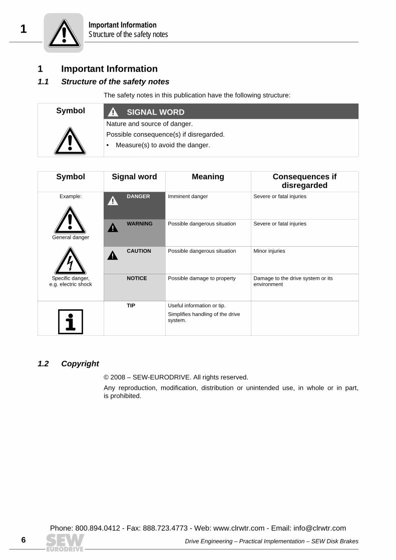
The safety notes in this publication have the following structure:
1.2 Copyright© 2008 – SEW-EURODRIVE. All rights reserved.Any reproduction, modification, distribution or unintended use, in whole or in part,is prohibited.
Symbol SIGNAL WORDNature and source of danger.Possible consequence(s) if disregarded.• Measure(s) to avoid the danger.
Symbol Signal word Meaning Consequences if disregarded
Example:
General danger
Specific danger,e.g. electric shock
DANGER Imminent danger Severe or fatal injuries
WARNING Possible dangerous situation Severe or fatal injuries
CAUTION Possible dangerous situation Minor injuries
NOTICE Possible damage to property Damage to the drive system or its environment
TIP Useful information or tip.Simplifies handling of the drive system.
ImS
Drive Engineering – Practical Implementation – SEW Disk Brakes
Phone: 800.894.0412 - Fax: 888.723.4773 - Web: www.clrwtr.com - Email: [email protected]
2IntroductionCopyrigh
2 IntroductionThis publication is designed for project planning engineers who intend to install ACmotors, servomotors or geared brakemotors from SEW-EURODRIVE. It provides infor-mation on the basic principles, special characteristics, intended use and electricalconnection of SEW brakemotors, and also includes sample circuits.Note that this documentation does not deal with the various safety conditions arising inspecific cases, nor with how they can be implemented in the motor control. Projectplanning engineers are responsible for these aspects of the system.The working principle and characteristic data of SEW disk brakes are also described inthe following SEW-EURODRIVE catalogs:• Gearmotors• DR Gearmotors• DR AC Motors• DR, CMP Motors• Synchronous Servo Gearmotors• Variable Speed Gearmotors• DTE/DVE Energy-efficient Motors• ASEPTIC GearmotorsDetailed information about basic sizing principles can be found in the SEW publication“Drive Planning” from the series “Drive Engineering – Practical Implementation.”All other information relating to drive calculations can also be found in this documenta-tion. The SEW project planning software “SEW Workbench” offers you support inmatters relating to configuration.For information on startup, operation and maintenance, refer to the relevant operatinginstructions.
Drive Engineering – Practical Implementation – SEW Disk Brakes
Phone: 800.894.0412 - Fax: 888.723.4773 - Web: www.clrwtr.com - Email: info@
tP
if
kVA
Hz
n
7clrwtr.com
3 rinciple of SEW Brakesasic design
8
3 Principle of SEW Brakes3.1 Basic design
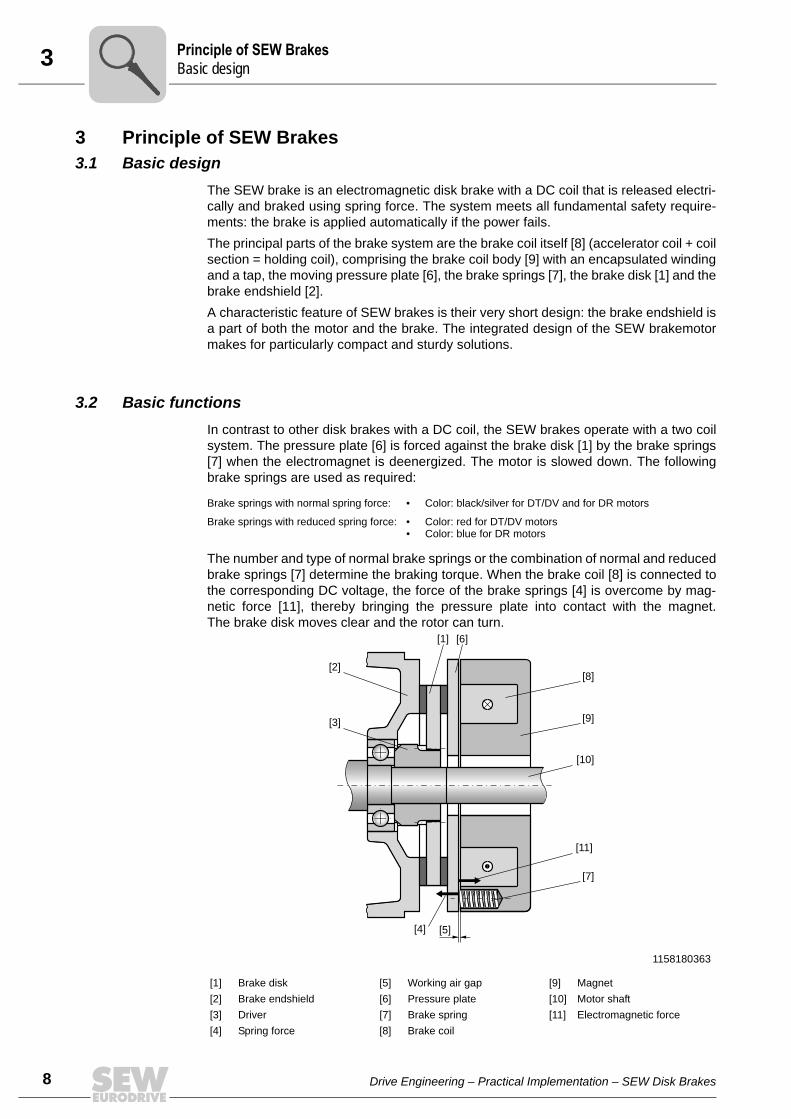
The SEW brake is an electromagnetic disk brake with a DC coil that is released electri-cally and braked using spring force. The system meets all fundamental safety require-ments: the brake is applied automatically if the power fails.The principal parts of the brake system are the brake coil itself [8] (accelerator coil + coilsection = holding coil), comprising the brake coil body [9] with an encapsulated windingand a tap, the moving pressure plate [6], the brake springs [7], the brake disk [1] and thebrake endshield [2].A characteristic feature of SEW brakes is their very short design: the brake endshield isa part of both the motor and the brake. The integrated design of the SEW brakemotormakes for particularly compact and sturdy solutions.
3.2 Basic functionsIn contrast to other disk brakes with a DC coil, the SEW brakes operate with a two coilsystem. The pressure plate [6] is forced against the brake disk [1] by the brake springs[7] when the electromagnet is deenergized. The motor is slowed down. The followingbrake springs are used as required:
The number and type of normal brake springs or the combination of normal and reducedbrake springs [7] determine the braking torque. When the brake coil [8] is connected tothe corresponding DC voltage, the force of the brake springs [4] is overcome by mag-netic force [11], thereby bringing the pressure plate into contact with the magnet.The brake disk moves clear and the rotor can turn.
Brake springs with normal spring force: • Color: black/silver for DT/DV and for DR motors
Brake springs with reduced spring force: • Color: red for DT/DV motors• Color: blue for DR motors
1158180363
[1] Brake disk [5] Working air gap [9] Magnet[2] Brake endshield [6] Pressure plate [10] Motor shaft[3] Driver [7] Brake spring [11] Electromagnetic force[4] Spring force [8] Brake coil
[5]
[11]
[10]
[9]
[8]
[7]
[6]
[3]
[2]
[1]
[4]
PB
Drive Engineering – Practical Implementation – SEW Disk Brakes
3Principle of SEW BrakesSEW brake systems in detai
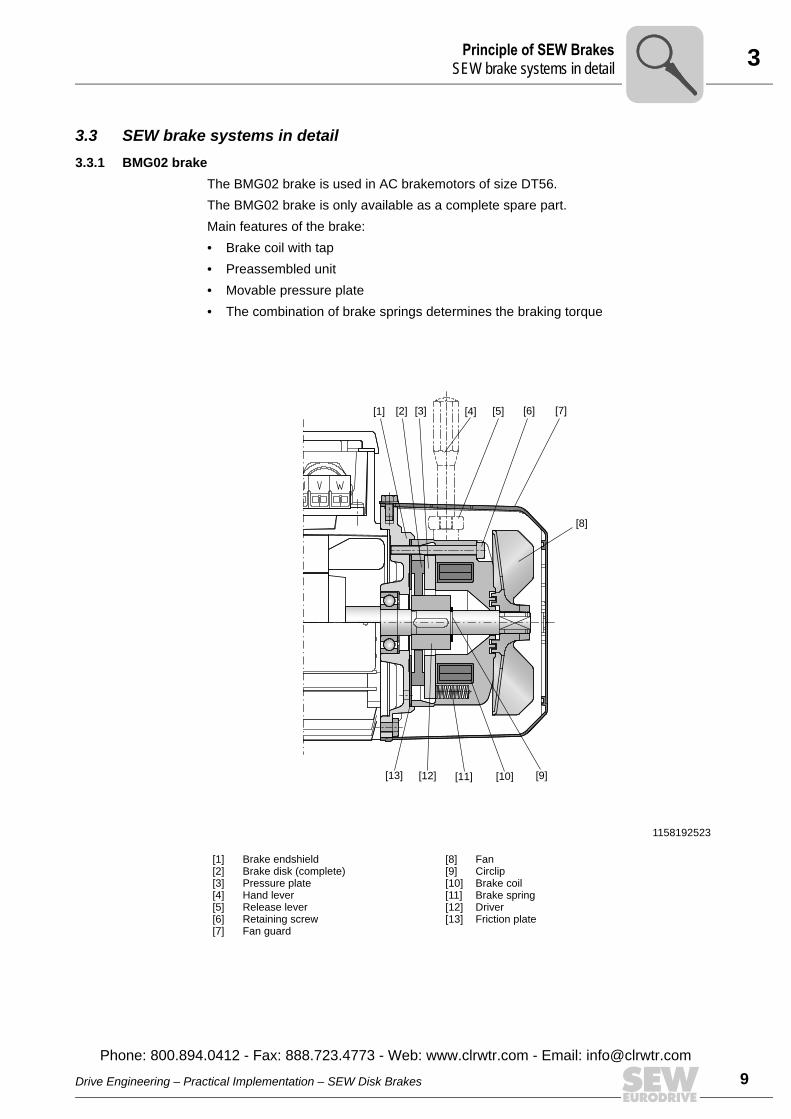
3.3 SEW brake systems in detail3.3.1 BMG02 brake
The BMG02 brake is used in AC brakemotors of size DT56.The BMG02 brake is only available as a complete spare part.Main features of the brake:• Brake coil with tap• Preassembled unit• Movable pressure plate• The combination of brake springs determines the braking torque
1158192523
[1][2][3][4][5][6][7]
Brake endshieldBrake disk (complete)Pressure plateHand leverRelease leverRetaining screw Fan guard
[8] [9] [10] [11] [12] [13]
FanCirclipBrake coilBrake springDriverFriction plate
[1] [2] [3] [4] [5] [6] [7]
[8]
[12][13] [11] [10] [9]
Drive Engineering – Practical Implementation – SEW Disk Brakes
Phone: 800.894.0412 - Fax: 888.723.4773 - Web: www.clrwtr.com - Email: info@
l
9clrwtr.com
3 rinciple of SEW BrakesEW brake systems in detail
10
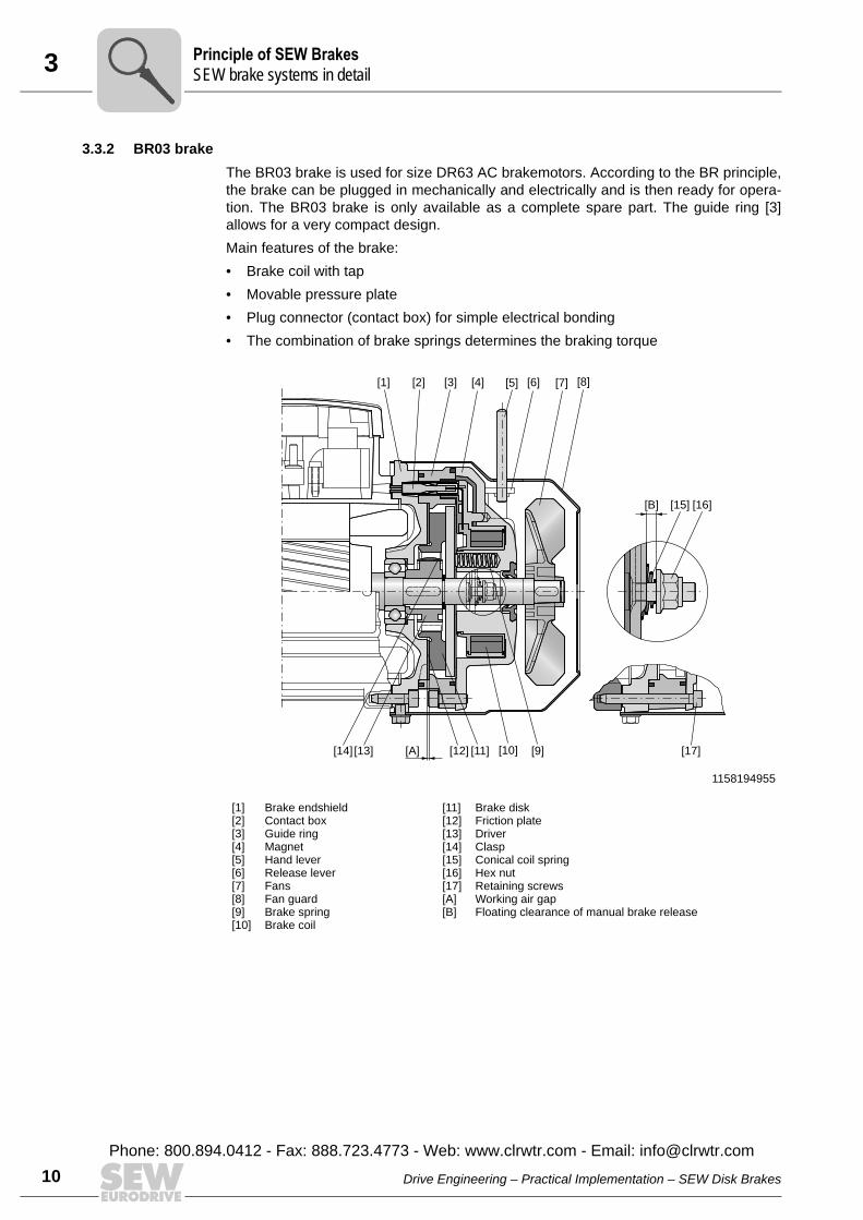
3.3.2 BR03 brakeThe BR03 brake is used for size DR63 AC brakemotors. According to the BR principle,the brake can be plugged in mechanically and electrically and is then ready for opera-tion. The BR03 brake is only available as a complete spare part. The guide ring [3]allows for a very compact design.Main features of the brake:• Brake coil with tap• Movable pressure plate• Plug connector (contact box) for simple electrical bonding• The combination of brake springs determines the braking torque
1158194955
[1][2][3][4][5][6][7][8][9][10]
Brake endshieldContact boxGuide ringMagnetHand leverRelease leverFansFan guardBrake springBrake coil
[11][12][13][14][15][16][17][A][B]
Brake diskFriction plateDriverClaspConical coil springHex nutRetaining screwsWorking air gapFloating clearance of manual brake release
[14] [13] [12][A] [11] [10] [9]
[1] [2] [3] [4] [5] [6] [7] [8]
[15] [16]
[17]
[B]
PS
Drive Engineering – Practical Implementation – SEW Disk Brakes
Phone: 800.894.0412 - Fax: 888.723.4773 - Web: www.clrwtr.com - Email: [email protected]
3Principle of SEW BrakesSEW brake systems in detai
3.3.3 BE.. brake The BE.. brake is used for AC motors DR.71 - DR.315.In the smaller DR.71 and DR.80 motors, the brake operates according to the principleof the BM(G), i.e. “brake integrated” directly on the endshield. The principle of the mod-ular brake on a friction disk begins starting at motor size DR.90. The modular brake allows for mounting of up to three brake sizes to one motor.The B-side endshield is to be regarded like a connecting flange, which accommodatesthe BE brake pre-mounted on a friction disk.Although the integrated brake is mounted on a complete brake endshield, it can bedimensioned to suit specific requirements, just like the modular brake.
Main features of the brake:• Various brake sizes can be mounted to each motor size• Brake coil with tap• Movable pressure plate• Plug connector for simple electrical connection, starting at BE20• The combination of brake springs determines the braking torque• Position of the manual brake release can be defined by the user
The working air gap [A] is set using the 3 retaining bolts [17] and the corresponding nuts[16], see Technical Data (see page 143).
Drive Engineering – Practical Implementation – SEW Disk Brakes
Phone: 800.894.0412 - Fax: 888.723.4773 - Web: www.clrwtr.com - Email: info@
l
11clrwtr.com
3 rinciple of SEW BrakesEW brake systems in detail
12
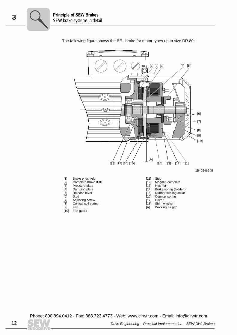
The following figure shows the BE.. brake for motor types up to size DR.80:
1540946699
[1][2][3][4][5][6][7][8][9][10]
Brake endshieldComplete brake diskPressure plateDamping plateRelease leverStudAdjusting screwConical coil springFanFan guard
[11][12][13][14][15][16][17][18][A]
StudMagnet, completeHex nutBrake spring (hidden)Rubber sealing collarCounter springDriverShim washerWorking air gap
[1] [2] [3]
[7]
[6]
[8]
[9]
[10]
[4] [5]
[18] [17] [16] [15] [13] [11][12]
[A]
[14]
PS
Drive Engineering – Practical Implementation – SEW Disk Brakes
Phone: 800.894.0412 - Fax: 888.723.4773 - Web: www.clrwtr.com - Email: [email protected]
3Principle of SEW BrakesSEW brake systems in detai
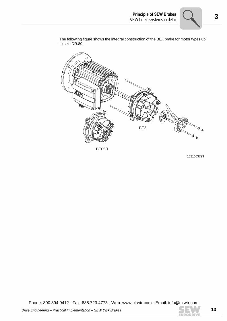
The following figure shows the integral construction of the BE.. brake for motor types upto size DR.80:
1521603723
BE05/1
BE2
Drive Engineering – Practical Implementation – SEW Disk Brakes
Phone: 800.894.0412 - Fax: 888.723.4773 - Web: www.clrwtr.com - Email: info@
l
13clrwtr.com

3 rinciple of SEW BrakesEW brake systems in detail
14
The following figure shows the BE.. brake for motor types from size DR.90:
1540949131
[1][2][3][4][5][6][7][8][9][10]
Brake endshieldComplete brake diskPressure plateDamping plateReleasing leverStudAdjusting screwConical coil springFansFan guard
[11][12][13][14][15][16][17][18][A]
StudMagnet, completeHex nutBrake spring (hidden)Rubber sealing collarCounter springDriverShim washerWorking air gap
[1] [2] [3]
[7]
[6]
[8]
[9]
[10]
[4] [5]
[18] [17] [16] [15] [13] [11][12]
[A]
[14]
PS
Drive Engineering – Practical Implementation – SEW Disk Brakes
Phone: 800.894.0412 - Fax: 888.723.4773 - Web: www.clrwtr.com - Email: [email protected]
3Principle of SEW BrakesSEW brake systems in detai
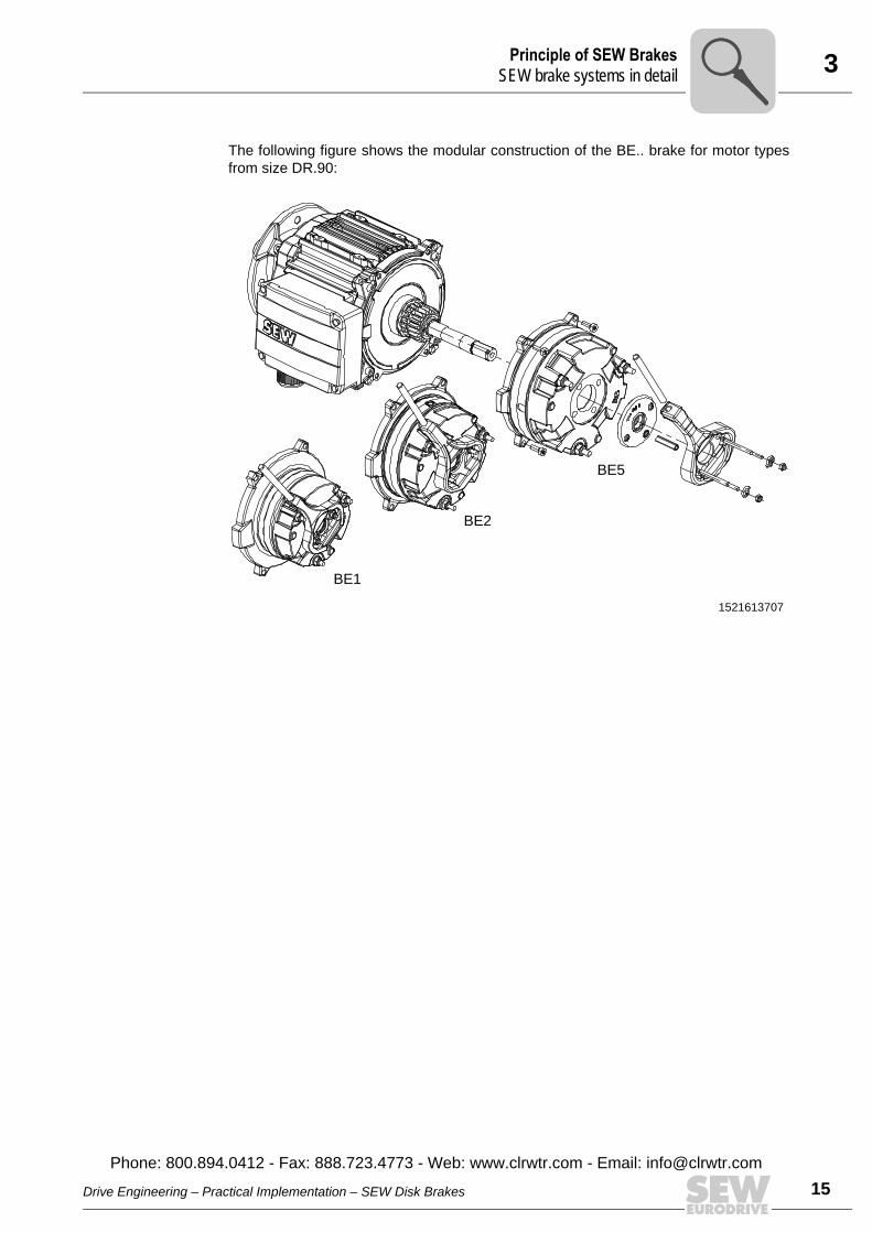
The following figure shows the modular construction of the BE.. brake for motor typesfrom size DR.90:
1521613707
BE1
BE5
BE2
Drive Engineering – Practical Implementation – SEW Disk Brakes
Phone: 800.894.0412 - Fax: 888.723.4773 - Web: www.clrwtr.com - Email: info@
l
15clrwtr.com
3 rinciple of SEW BrakesEW brake systems in detail
16
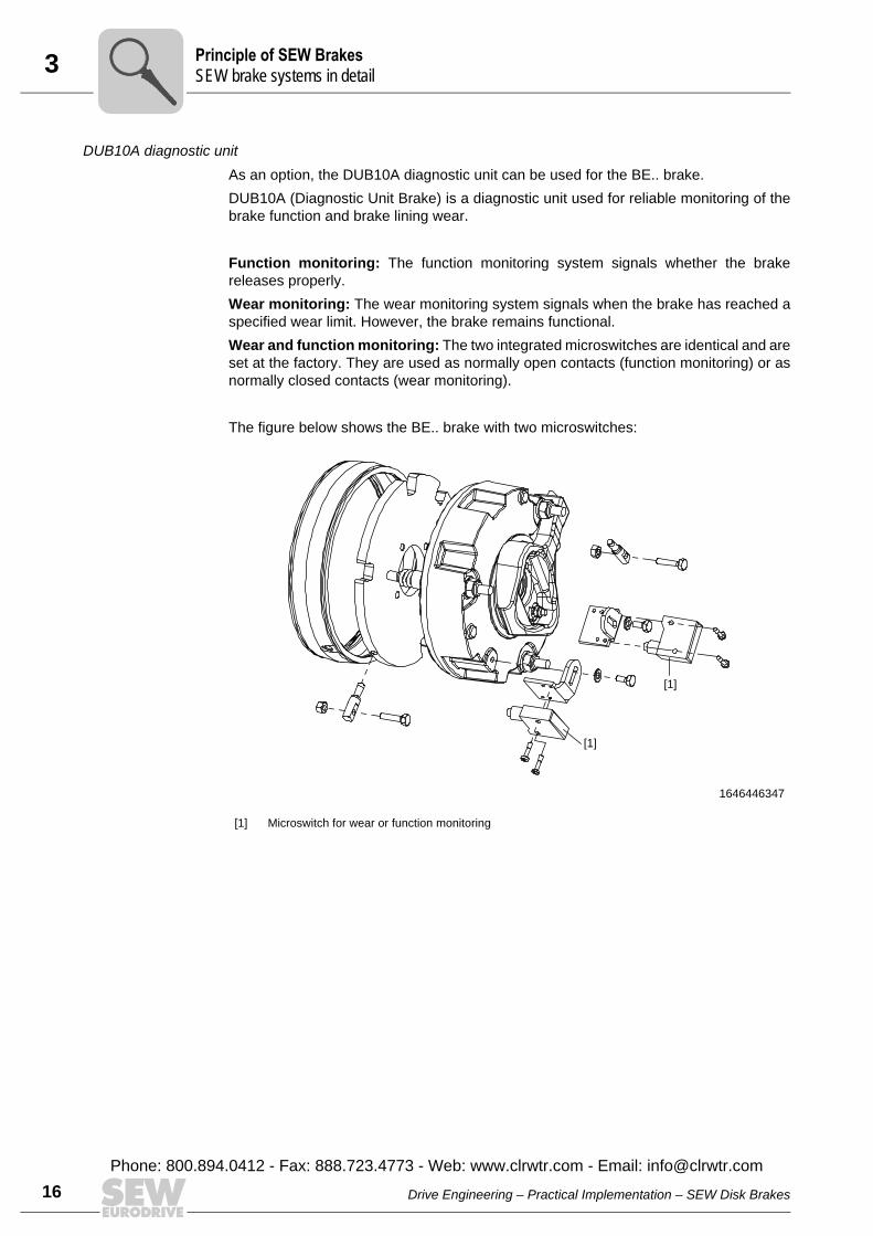
DUB10A diagnostic unitAs an option, the DUB10A diagnostic unit can be used for the BE.. brake.DUB10A (Diagnostic Unit Brake) is a diagnostic unit used for reliable monitoring of thebrake function and brake lining wear.
Function monitoring: The function monitoring system signals whether the brakereleases properly.Wear monitoring: The wear monitoring system signals when the brake has reached aspecified wear limit. However, the brake remains functional.Wear and function monitoring: The two integrated microswitches are identical and areset at the factory. They are used as normally open contacts (function monitoring) or asnormally closed contacts (wear monitoring).
The figure below shows the BE.. brake with two microswitches:
1646446347
[1] Microswitch for wear or function monitoring
[1]
[1]
PS
Drive Engineering – Practical Implementation – SEW Disk Brakes
Phone: 800.894.0412 - Fax: 888.723.4773 - Web: www.clrwtr.com - Email: [email protected]
3Principle of SEW BrakesSEW brake systems in detai
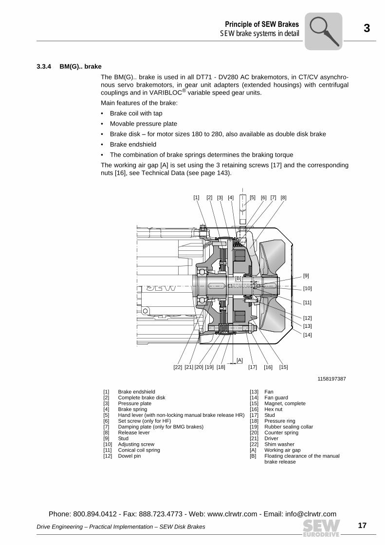
3.3.4 BM(G).. brakeThe BM(G).. brake is used in all DT71 - DV280 AC brakemotors, in CT/CV asynchro-nous servo brakemotors, in gear unit adapters (extended housings) with centrifugalcouplings and in VARIBLOC® variable speed gear units.Main features of the brake: • Brake coil with tap • Movable pressure plate • Brake disk – for motor sizes 180 to 280, also available as double disk brake • Brake endshield • The combination of brake springs determines the braking torqueThe working air gap [A] is set using the 3 retaining screws [17] and the correspondingnuts [16], see Technical Data (see page 143).
1158197387
[1][2][3][4][5][6][7][8][9][10][11][12]
Brake endshieldComplete brake diskPressure plateBrake springHand lever (with non-locking manual brake release HR)Set screw (only for HF)Damping plate (only for BMG brakes)Release leverStudAdjusting screwConical coil springDowel pin
[13][14][15][16][17][18][19][20][21][22][A][B]
FanFan guardMagnet, completeHex nutStudPressure ringRubber sealing collarCounter springDriverShim washerWorking air gapFloating clearance of the manual brake release
[1] [2] [3] [4] [5] [6] [7] [8]
[22] [21] [20] [19] [18] [17] [16] [15]
[10]
[9]
[11]
[12]
[13]
[14]
[A]
[B]
Drive Engineering – Practical Implementation – SEW Disk Brakes
Phone: 800.894.0412 - Fax: 888.723.4773 - Web: www.clrwtr.com - Email: info@
l
17clrwtr.com
3 rinciple of SEW BrakesEW brake systems in detail
18
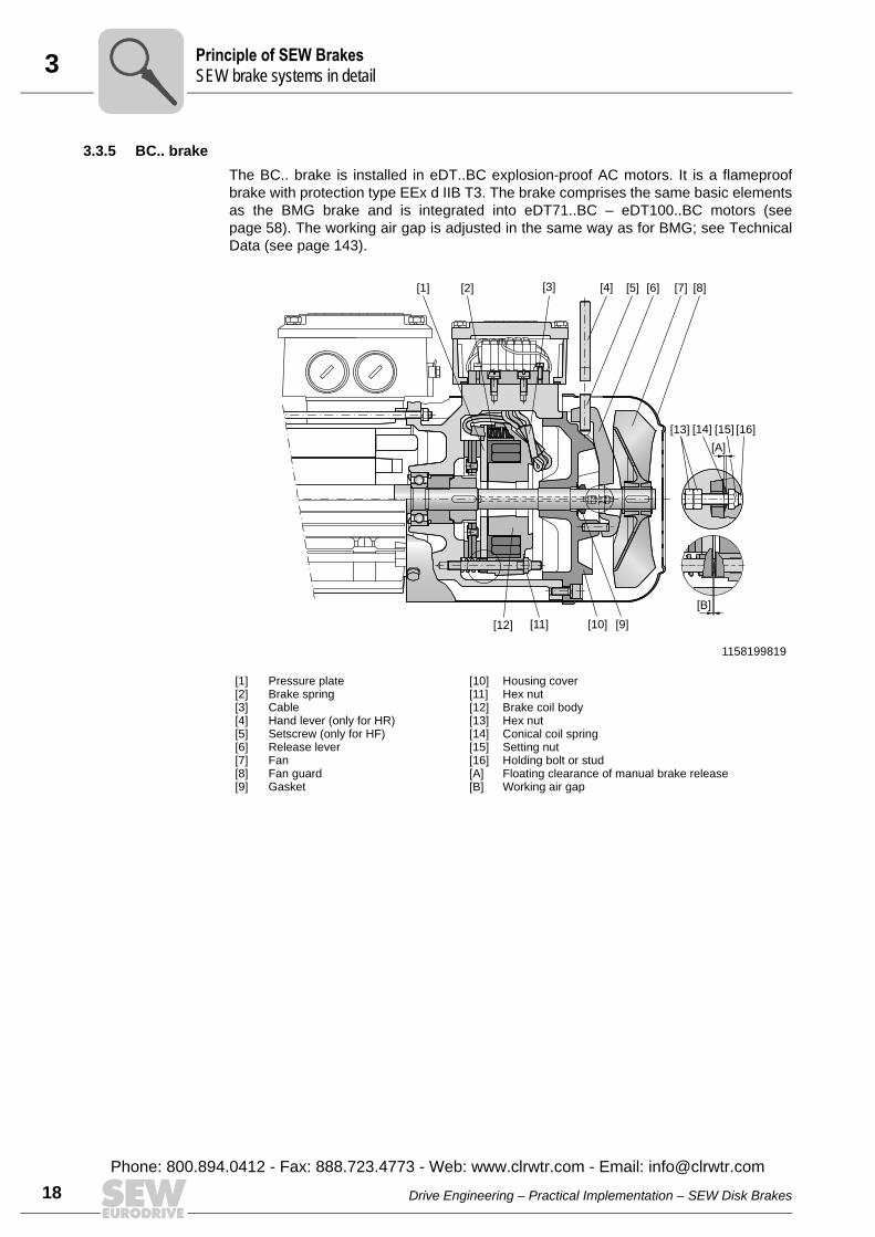
3.3.5 BC.. brakeThe BC.. brake is installed in eDT..BC explosion-proof AC motors. It is a flameproofbrake with protection type EEx d IIB T3. The brake comprises the same basic elementsas the BMG brake and is integrated into eDT71..BC – eDT100..BC motors (seepage 58). The working air gap is adjusted in the same way as for BMG; see TechnicalData (see page 143).
1158199819
[1][2][3][4][5][6][7][8][9]
Pressure plateBrake springCableHand lever (only for HR)Setscrew (only for HF)Release leverFanFan guardGasket
[10][11][12][13][14][15][16][A][B]
Housing coverHex nutBrake coil bodyHex nutConical coil springSetting nutHolding bolt or studFloating clearance of manual brake releaseWorking air gap
[1] [2] [3] [4] [5] [6] [7] [8]
[13]
[12] [11] [10] [9]
[14] [15]
[A]
[16]
[B]
PS
Drive Engineering – Practical Implementation – SEW Disk Brakes
Phone: 800.894.0412 - Fax: 888.723.4773 - Web: www.clrwtr.com - Email: [email protected]
3Principle of SEW BrakesSEW brake systems in detai
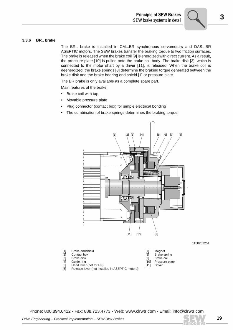
3.3.6 BR.. brakeThe BR.. brake is installed in CM...BR synchronous servomotors and DAS...BRASEPTIC motors. The SEW brakes transfer the braking torque to two friction surfaces.The brake is released when the brake coil [9] is energized with direct current. As a result,the pressure plate [10] is pulled onto the brake coil body. The brake disk [3], which isconnected to the motor shaft by a driver [11], is released. When the brake coil isdeenergized, the brake springs [8] determine the braking torque generated between thebrake disk and the brake bearing end shield [1] or pressure plate.The BR brake is only available as a complete spare part.Main features of the brake:• Brake coil with tap• Movable pressure plate• Plug connector (contact box) for simple electrical bonding• The combination of brake springs determines the braking torque
1158202251
[1][2][3][4][5][6]
Brake endshieldContact boxBrake diskGuide ringHand lever (not for HF)Release lever (not installed in ASEPTIC motors)
[7][8][9][10][11]
MagnetBrake springBrake coilPressure plateDriver
[1] [2] [3] [4] [5] [6] [7] [8]
[11] [10] [9]
Drive Engineering – Practical Implementation – SEW Disk Brakes
Phone: 800.894.0412 - Fax: 888.723.4773 - Web: www.clrwtr.com - Email: info@
l
19clrwtr.com
3 rinciple of SEW BrakesEW brake systems in detail
20
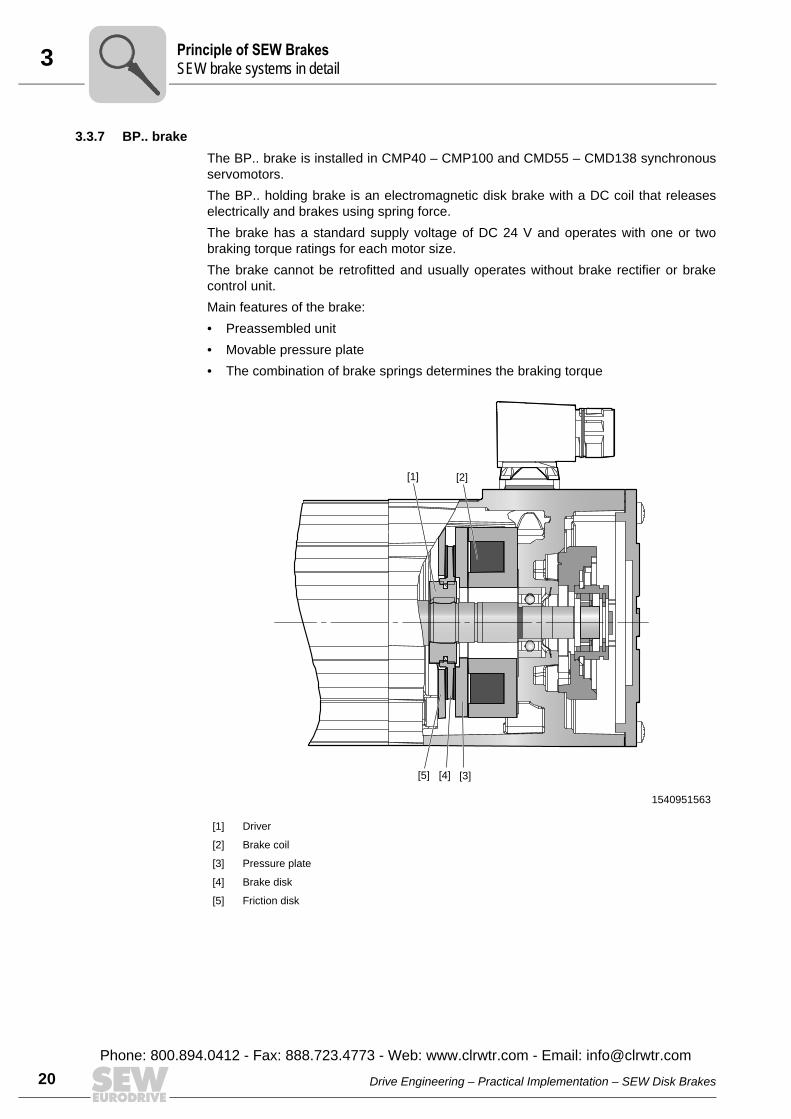
3.3.7 BP.. brakeThe BP.. brake is installed in CMP40 – CMP100 and CMD55 – CMD138 synchronousservomotors.The BP.. holding brake is an electromagnetic disk brake with a DC coil that releaseselectrically and brakes using spring force. The brake has a standard supply voltage of DC 24 V and operates with one or twobraking torque ratings for each motor size. The brake cannot be retrofitted and usually operates without brake rectifier or brakecontrol unit. Main features of the brake:• Preassembled unit• Movable pressure plate• The combination of brake springs determines the braking torque
1540951563
[1] Driver
[2] Brake coil
[3] Pressure plate
[4] Brake disk
[5] Friction disk
[1] [2]
[5] [4] [3]
PS
Drive Engineering – Practical Implementation – SEW Disk Brakes
Phone: 800.894.0412 - Fax: 888.723.4773 - Web: www.clrwtr.com - Email: [email protected]
3Principle of SEW BrakesSEW brake systems in detai
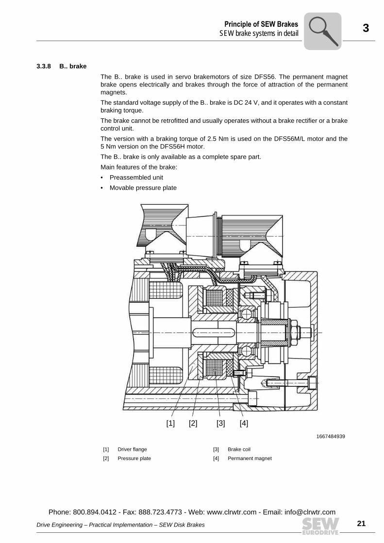
3.3.8 B.. brakeThe B.. brake is used in servo brakemotors of size DFS56. The permanent magnetbrake opens electrically and brakes through the force of attraction of the permanentmagnets.The standard voltage supply of the B.. brake is DC 24 V, and it operates with a constantbraking torque. The brake cannot be retrofitted and usually operates without a brake rectifier or a brakecontrol unit. The version with a braking torque of 2.5 Nm is used on the DFS56M/L motor and the5 Nm version on the DFS56H motor.The B.. brake is only available as a complete spare part.Main features of the brake:• Preassembled unit• Movable pressure plate
1667484939
[1] Driver flange [3] Brake coil
[2] Pressure plate [4] Permanent magnet
[1] [2] [3] [4]
Drive Engineering – Practical Implementation – SEW Disk Brakes
Phone: 800.894.0412 - Fax: 888.723.4773 - Web: www.clrwtr.com - Email: info@
l
21clrwtr.com

4 umerous Possibilities Using Modular Brake ControlsEW brake systems in detail
22
4 Numerous Possibilities Using Modular Brake ControlsThe SEW brake system, just like the entire product range of SEW-EURODRIVE, has amodular structure. The modular concept consisting of electronic and mechanical com-ponents permits a wide variety of tasks to be accomplished.In the mechanical range of the modular units, there are various types to be considered,such as adjustable braking torques and additional options. Electronic components, on the other hand, make different control systems and functionsavailable, such as high-speed excitation or a heating function. In this way, all SEW brake systems share one basic principle, which is adapted to thebroadest variety of possible uses by combining elements from the modular concept.The following table gives an overview of the possible combinations of brakes and con-trols and the resulting properties.
Installation in terminal box
BG BGE BSR BUR BS BSG
Standard excitation – O1)
1) Standard excitation is only possible for DR63.
O1) –
High-speed excitation – –
Standard application – – –
Rapid application O2)
2) This combination is only possible together with switch contacts in utilization category AC-3 with SR.. orUR.. for BG and BGE.
O2) –
Heating function – – – – – –
Connection, DC 24 V brake – – – –
Connection, explosion-proof motors – – – – – 3)
3) The BSG brake control must be installed in the control cabinet.
Installation in control cabinet
BMS BME BMH BMP1)
1) The BMP brake control can also be in the terminal box with the DR315 motor.
BMK BMV
Standard excitation – – – – –
High-speed excitation –
Standard application O2)
2) This combination is only possible by applying a jumper.
– –
Rapid application O3)
3) This combination is only possible together with contacts in utilization category AC-3.
O3) O3)
Heating function – – – – –
Connection, DC 24 V brake – – – – –
DC 24 V control input – – – –
Connection, explosion-proof motors – – – –
Possible
O Only possible to a certain extent
– Not possible
NS
Pi
fkVA
Hz
n
Drive Engineering – Practical Implementation – SEW Disk Brakes
Phone: 800.894.0412 - Fax: 888.723.4773 - Web: www.clrwtr.com - Email: [email protected]
4Numerous Possibilities Using Modular Brake ControlsParticularly short response times at switch-on
The following features are explained in more detail in the next sections:• Particularly short response times at switch-on• Particularly short response times at switch-off• Particularly safe• High stopping accuracy• High starting frequency possible• Low noise level• High thermal load possible• Low and fluctuating ambient temperatures possible
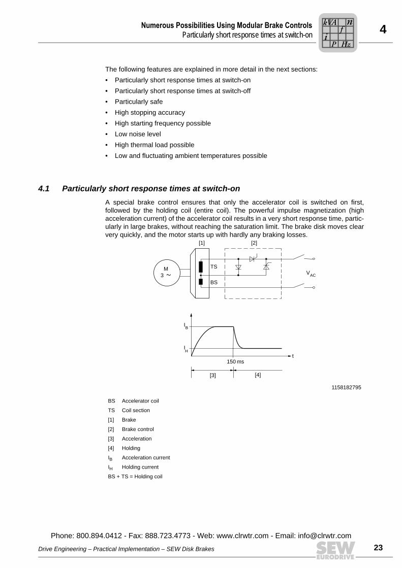
4.1 Particularly short response times at switch-onA special brake control ensures that only the accelerator coil is switched on first,followed by the holding coil (entire coil). The powerful impulse magnetization (highacceleration current) of the accelerator coil results in a very short response time, partic-ularly in large brakes, without reaching the saturation limit. The brake disk moves clearvery quickly, and the motor starts up with hardly any braking losses.
1158182795
BS Accelerator coil
TS Coil section
[1] Brake
[2] Brake control
[3] Acceleration
[4] Holding
IB Acceleration current
IH Holding current
BS + TS = Holding coil
150 ms
IB
t
IH
M
3
TS
BS
VAC
[1] [2]
[3] [4]
Drive Engineering – Practical Implementation – SEW Disk Brakes
Phone: 800.894.0412 - Fax: 888.723.4773 - Web: www.clrwtr.com - Email: info@
Pi
fkVA
Hz
n
23clrwtr.com
4 umerous Possibilities Using Modular Brake Controlsarticularly short response times at switch-on
24
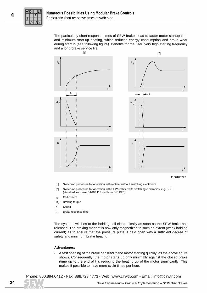
The particularly short response times of SEW brakes lead to faster motor startup timeand minimum start-up heating, which reduces energy consumption and brake wearduring startup (see following figure). Benefits for the user: very high starting frequencyand a long brake service life.
The system switches to the holding coil electronically as soon as the SEW brake hasreleased. The braking magnet is now only magnetized to such an extent (weak holdingcurrent) as to ensure that the pressure plate is held open with a sufficient degree ofsafety and minimum brake heating.
Advantages:• A fast opening of the brake can lead to the motor starting quickly, as the above figure
shows. Consequently, the motor starts up only minimally against the closed brake(time up to the end of t1), reducing the heating up of the motor significantly. Thismakes it possible to have more cycle times per hour.
1158185227
[1] Switch-on procedure for operation with rectifier without switching electronics
[2] Switch-on procedure for operation with SEW rectifier with switching electronics, e.g. BGE (standard from size DT/DV 112 and from DR..BE5)
IS Coil current
MB Braking torque
n Speed
t1 Brake response time
t1t1
t t
t t
t t
IS IS
M B M B
n n
[1] [2]
NP
Pi
fkVA
Hz
n
Drive Engineering – Practical Implementation – SEW Disk Brakes
Phone: 800.894.0412 - Fax: 888.723.4773 - Web: www.clrwtr.com - Email: [email protected]

4Numerous Possibilities Using Modular Brake ControlsHigh starting frequency possible
4.2 High starting frequency possibleBrakemotors often demand a high starting frequency and significant external massmoments of inertia.In addition to the basic thermal suitability of the motor, the brake needs to have aresponse time t1 short enough to ensure that it is already released when the motorstarts. At the same time, the acceleration required for the mass moment of inertia alsohas to be taken into account. Without the usual startup phase when the brake is stillapplied, the temperature and wear balance of the SEW brake permits a high startingfrequency.Brakes from BMG8 – BMG122 and BE5 – BE122 are designed for a high startingfrequency as standard.
The table below shows that, in addition to BGE (BME) and BSG, the BSR, BUR, BMH,BMK and BMP brake controls also have properties for shortening the response time inaddition to their other functions.
Type Brakemotor
High starting frequency
Brake control for AC connection Brake control for DC 24 V connection
DR63..BR BME (BMH, BMP, BMK) in control cabinet BSG and BMV in control cabinet
DT71..BMG
BGE (BSR, BUR) in terminal box or BME(BMH, BMP, BMK) in control cabinet
BSG in terminal box or BMV and BSG in control
cabinet
DT80..BMG
DT90..BMG
DV100..BMG
DV112..BMG
DV132S..BMG
DV132M..BM
DV132ML..BM
DV160..BM
DV180..BM
DV200..BM
DV225..BM
DV250..BMGBGE in terminal box or BME in control cabinet -
DV280..BMG
BrakeHigh starting frequency
Brake control for AC connection Brake control for DC 24 V connection
BE05
BGE (BSR, BUR) in terminal box or BME(BMH, BMP, BMK) in control cabinet
BSG in terminal box or BMV and BSG in control
cabinet
BE1
BE2
BE5
BE11
BE20
BE30BGE in terminal box or BME in control cabinet
-BE32
BE120BMP3.1 in the terminal box or the control cabinet
BE122
Drive Engineering – Practical Implementation – SEW Disk Brakes
Phone: 800.894.0412 - Fax: 888.723.4773 - Web: www.clrwtr.com - Email: info@
Pi
fkVA
Hz
n
25clrwtr.com
4 umerous Possibilities Using Modular Brake Controlsarticularly short response times at switch-off
26
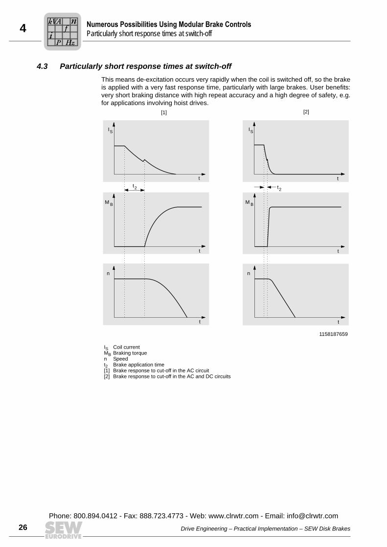
4.3 Particularly short response times at switch-offThis means de-excitation occurs very rapidly when the coil is switched off, so the brakeis applied with a very fast response time, particularly with large brakes. User benefits:very short braking distance with high repeat accuracy and a high degree of safety, e.g.for applications involving hoist drives.
1158187659
IS Coil currentMB Braking torquen Speedt2 Brake application time[1] Brake response to cut-off in the AC circuit[2] Brake response to cut-off in the AC and DC circuits
t
t
t
IS
M B
n
[1] [2]
t2 t2
IS
M B
n
t
t
t
NP
Pi
fkVA
Hz
n
Drive Engineering – Practical Implementation – SEW Disk Brakes
Phone: 800.894.0412 - Fax: 888.723.4773 - Web: www.clrwtr.com - Email: [email protected]
4Numerous Possibilities Using Modular Brake ControlsParticularly short response times at switch-of
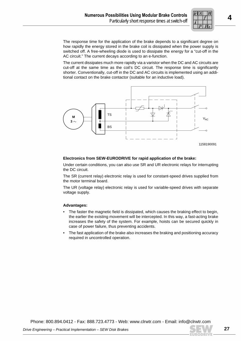
The response time for the application of the brake depends to a significant degree onhow rapidly the energy stored in the brake coil is dissipated when the power supply isswitched off. A free-wheeling diode is used to dissipate the energy for a “cut-off in theAC circuit.” The current decays according to an e-function.The current dissipates much more rapidly via a varistor when the DC and AC circuits arecut-off at the same time as the coil’s DC circuit. The response time is significantlyshorter. Conventionally, cut-off in the DC and AC circuits is implemented using an addi-tional contact on the brake contactor (suitable for an inductive load).
Electronics from SEW-EURODRIVE for rapid application of the brake:Under certain conditions, you can also use SR and UR electronic relays for interruptingthe DC circuit.The SR (current relay) electronic relay is used for constant-speed drives supplied fromthe motor terminal board.The UR (voltage relay) electronic relay is used for variable-speed drives with separatevoltage supply.
Advantages:• The faster the magnetic field is dissipated, which causes the braking effect to begin,
the earlier the existing movement will be intercepted. In this way, a fast-acting brakeincreases the safety of the system. For example, hoists can be secured quickly incase of power failure, thus preventing accidents.
• The fast application of the brake also increases the braking and positioning accuracyrequired in uncontrolled operation.
1158190091
ACM
3
TS
BS
V
Drive Engineering – Practical Implementation – SEW Disk Brakes
Phone: 800.894.0412 - Fax: 888.723.4773 - Web: www.clrwtr.com - Email: info@
fP
if
kVA
Hz
n
27clrwtr.com
4 umerous Possibilities Using Modular Brake Controlsigh stopping accuracy
28
4.4 High stopping accuracyPositioning systems require high stopping accuracy.Due to their mechanical principle, the degree of wear on the linings, and on-site basicphysical conditions, brakemotors are subject to an empirically determined brakingdistance variation of ±12%. The shorter the response times (see page 26), the smallerthe absolute value of the variation.Cut-off in the DC and AC circuits makes it possible to shorten the brake application timet2 considerably.
Cut-off in the DC and AC circuits with mechanical contact:The sections “Basic functions” (see page 8) and “Standard brake control” (see page 31)have already referred to the possibility of achieving this solution by conventional meansby using an extra contact.
Cut-off in the DC and AC circuits with electronic relay in the terminal box:The BSR and BUR brake controls offer particularly elegant possibilities involving anelectronic, wear-free contact at the same time as minimum wiring work (see page 33 andfollowing). Both control systems are made up of BGE (BG for size 63) and either the SRcurrent relay or UR voltage relay.BSR is only suitable for single-speed motors. BUR can be installed universally ifit has a separate power supply.When ordering the brakemotor, it is sufficient to specify BSR and BUR in conjunctionwith the motor or brake voltage. The SEW order processing system assigns a suitablerelay. The proper relays for possible retrofitting and those for motor and voltage can be foundin the sections “Principle and selection of the BSR/BUR brake control.” The electronicrelays can switch up to 1 A brake current, thereby limiting the selection to BSR and BUR.
NH
Pi
fkVA
Hz
n
Drive Engineering – Practical Implementation – SEW Disk Brakes
Phone: 800.894.0412 - Fax: 888.723.4773 - Web: www.clrwtr.com - Email: [email protected]
4Numerous Possibilities Using Modular Brake ControlsParticularly safe
4.5 Particularly safeTried and tested design components and brake controls tested in trial applicationsensure that the SEW brake has a high degree of operational safety. Due to the fail-safeprinciple, the brake is closed by spring force if the coil is not under current. Conse-quently, the brake always goes back to a safe condition in case of power failure.
Advantages:• The sturdy mechanical components of the brake are designed to withstand several
times the rated load. Because of SEW-EURODRIVE’s great deal of experience, thebrake linings are carefully adapted to meet customer needs and have proven them-selves in many years of operation.
• In addition to reliable standard brake controls, one can also select safety-orientedcontrol systems, such as BST (see the publication “Safety-Oriented BST BrakeModule”).
4.6 Low noise levelMany applications in the power range up to approx. 5.5 kW (4-pole) require particularlyquiet brakemotors to reduce noise pollution. SEW-EURODRIVE implements specialdesign measures to meet these requirements as standard for all AC brakemotors up tosize DV132S and for all motors from the DR modular series without affecting the specialdynamic features of the brake system.
Advantages:• The surrounding area will not affected by noise caused by brakes. The noise
damping does not change the time the brake requires for switching on and off. Possible places of use for noise-damping brakes could be, for example, the theater.Because of their quiet application and opening, the brakes would not be heard by theaudience.
4.7 High thermal load possibleIn addition to the basic considerations, elevated ambient temperature, insufficientsupply of cooling air and/or thermal class 180 (H) are reasons for installing the brakecontrol in the control cabinet.Only brake controls with electronic switching are used in order to ensure reliableswitching at higher winding temperatures in the brake.The use of BGE, BME or BSG instead of BG, BMS or DC 24 V direct connection is pre-scribed for the special case represented by “electronic brake release when motor atstandstill” for brake sizes BMG05 – BMG4 and brake sizes BE05 – BE2.Special designs of brakemotors for increased thermal loading must be equipped withbrake controls in the control cabinet.
Drive Engineering – Practical Implementation – SEW Disk Brakes
Phone: 800.894.0412 - Fax: 888.723.4773 - Web: www.clrwtr.com - Email: info@
Pi
fkVA
Hz
n
29clrwtr.com
4 umerous Possibilities Using Modular Brake Controlsow and fluctuating ambient temperatures possible
30
4.8 Low and fluctuating ambient temperatures possibleBrakemotors for low and fluctuating ambient temperatures, e.g. for use outdoors, areexposed to the dangers of condensation and icing. Functional limitations due to corro-sion and ice can be counteracted by using the BMH brake control with the additionalfunction “anti-condensation heating.”The “heating” function is activated externally. As soon as the brake has been appliedand the heating function switched on during lengthy breaks, both coil sections of theSEW brake system are supplied with reduced voltage in an inverse-parallel connectionby a thyristor operating at a reduced control factor setting. On the one hand, this practi-cally eliminates the induction effect (brake does not release). On the other hand, it givesrise to heating in the coil system, increasing the temperature by approx. 25 K in relationto the ambient temperature.The heating function (via K16 in the sample circuits) must be ended before the brakestarts its normal switching function again.The BMH brake control, which is available for all motor sizes and is installed only in thecontrol cabinet, provides the anti-condensation heating. Brakes with the BMH brake control can be used in this way with a reduced functionalrange at temperatures of -40 to +100 °C.
4.9 Direct control using a frequency inverterThe BMK and BMV brake controls serve as units that can be directly controlled usingthe brake command of a frequency inverter. No other switching elements are required. BMK and BMV brake controls energize the brake as soon as the power supply and a DC24 V control signal are present. The releasing and application of the brake occurs withan especially short reaction time.For safety reasons, all poles must be switched off upon an emergency stop.
NL
Pi
fkVA
Hz
n
Drive Engineering – Practical Implementation – SEW Disk Brakes
Phone: 800.894.0412 - Fax: 888.723.4773 - Web: www.clrwtr.com - Email: [email protected]
5Brake Controls in DetaiStandard brake contro
5 Brake Controls in DetailVarious brake controls are available for controlling disk brakes with a DC coil, dependingon the requirements and the operating conditions. All brake controls are fitted asstandard with varistors to protect against overvoltage. The brake controls are either installed directly in the wiring space on the motor or in thecontrol cabinet. For motors of thermal class 180 (H) and explosion-proof motors(eDT..BC), the control system must be installed in the control cabinet.Various brake controls for installation in the terminal box or in the control cabinet meanthat the optimum solution can be found for all applications and conditions.The standard type is supplied unless particular requirements are made.
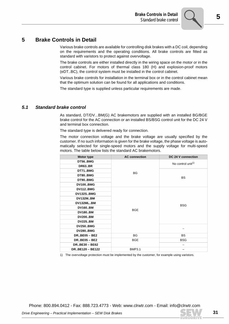
5.1 Standard brake controlAs standard, DT/DV...BM(G) AC brakemotors are supplied with an installed BG/BGEbrake control for the AC connection or an installed BS/BSG control unit for the DC 24 Vand terminal box connection.The standard type is delivered ready for connection.The motor connection voltage and the brake voltage are usually specified by thecustomer. If no such information is given for the brake voltage, the phase voltage is auto-matically selected for single-speed motors and the supply voltage for multi-speedmotors. The table below lists the standard AC brakemotors.
Motor type AC connection DC 24 V connectionDT56..BMG
BG
No control unit1)
1) The overvoltage protection must be implemented by the customer, for example using varistors.
DR63..BRDT71..BMG
BSDT80..BMGDT90..BMG
DV100..BMGDV112..BMG
BGEBSG
DV132S..BMGDV132M..BM
DV132ML..BMDV160..BMDV180..BMDV200..BMDV225..BM
DV250..BMG–
DV280..BMGDR..BE05 – BE2 BG BSDR..BE05 – BE2 BGE BSGDR..BE30 – BE62 –
DR..BE120 – BE122 BMP3.1 –
Drive Engineering – Practical Implementation – SEW Disk Brakes
Phone: 800.894.0412 - Fax: 888.723.4773 - Web: www.clrwtr.com - Email: info@
ll
31clrwtr.com
5 rake Controls in Detailtandard brake control
32
For brake applications with higher starting frequencies, different brake controls areused.Either cut-off in the AC circuit or cut-off in both the DC and AC circuits is possible withstandard versions for AC connection.The brake voltage can either be supplied separately (particularly with multi-speedmotors) or taken directly from the motor terminal board (with single-speed motors).The response times t2I for cut-off in the AC circuit (see page 106) apply to the separatepower supply. With the terminal board connection, switching the motor off with remanentenergization leads to a further delay before the brake is applied.The specified brake controls have powerful overvoltage protection for the brake coil andswitching contact.No brake control is supplied with the standard version for DC 24 V voltage supply ofDT56..BMG and DR63..BR motors. The customer must install suitable overvoltage pro-tection.
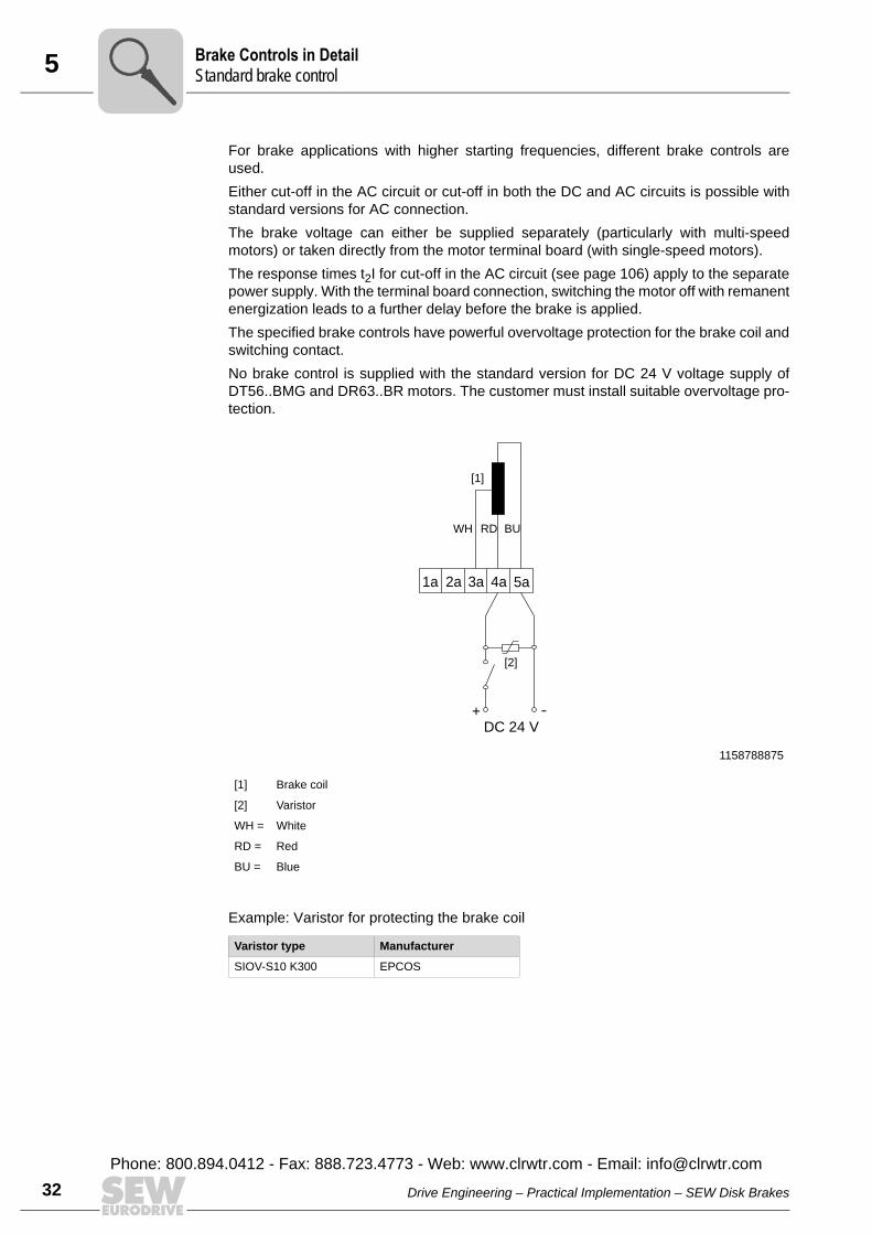
Example: Varistor for protecting the brake coil
1158788875
[1] Brake coil
[2] Varistor
WH = White
RD = Red
BU = Blue
Varistor type Manufacturer
SIOV-S10 K300 EPCOS
+ -
1a 2a 3a 4a
DC 24 V
WH RD BU
5a
[1]
[2]
BS
Drive Engineering – Practical Implementation – SEW Disk Brakes
Phone: 800.894.0412 - Fax: 888.723.4773 - Web: www.clrwtr.com - Email: [email protected]

5Brake Controls in DetaiPrinciple and selection of the BSR brake contro
5.2 Principle and selection of the BSR brake controlThe BSR brake control combines the BGE control unit with an electrical current relay.With BSR, the BGE (BG for DR63) is supplied with voltage directly from the terminalboard of a single-speed motor, which means that it does not need a special supplycable.When the motor is disconnected, the motor current is interrupted practically instanta-neously and is used for cut-off in the DC circuit of the brake coil via the SR current relay.This feature results in particularly fast brake application despite the residual voltage atthe motor terminal board and in the brake control (see page 67).The brake voltage is defined automatically on the basis of the motor phase voltagewithout further customer data (e.g. motor 230 V/400 V, brake 230 V). As an option, thebrake coil can also be configured for the line-to-line voltage (e.g. motor 400 V, brake400 V).The allocation of current relay and brake rectifier is made in the order depending on thespecified motor and brake voltages.The following table shows the allocation of SR current relay to the rated motor currentIN [A] in Õ connection and the maximum holding current of the brake IHmax [A].IHmax= IH × 1.3 [AC A]
Current relay Rated motor current IN [A] in Õ connection
Max. holding current of the brake IHmax [A]
SR11 0.6 - 10 1
SR15 10 - 50 1
SR19 50 - 90 1
Drive Engineering – Practical Implementation – SEW Disk Brakes
Phone: 800.894.0412 - Fax: 888.723.4773 - Web: www.clrwtr.com - Email: info@
ll
33clrwtr.com
5 rake Controls in Detailrinciple and selection of the BUR brake control
34
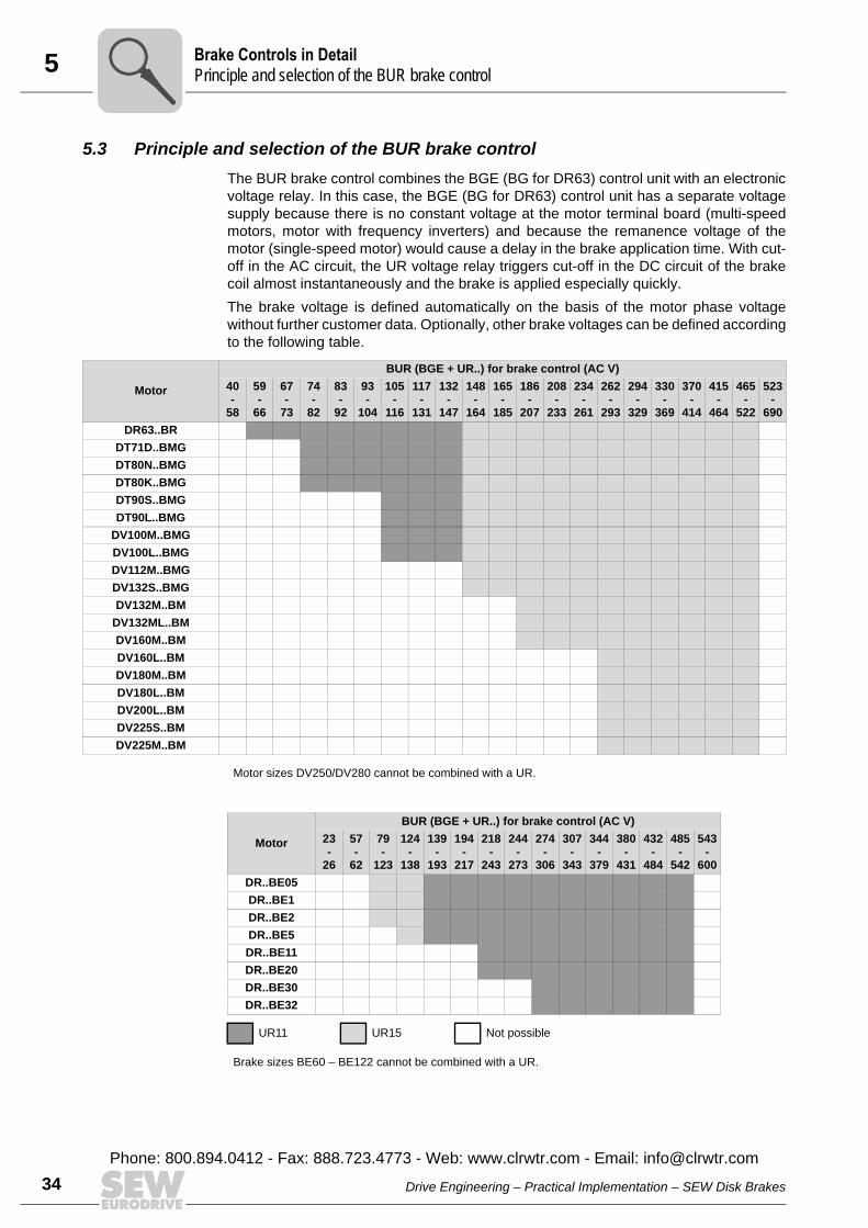
5.3 Principle and selection of the BUR brake controlThe BUR brake control combines the BGE (BG for DR63) control unit with an electronicvoltage relay. In this case, the BGE (BG for DR63) control unit has a separate voltagesupply because there is no constant voltage at the motor terminal board (multi-speedmotors, motor with frequency inverters) and because the remanence voltage of themotor (single-speed motor) would cause a delay in the brake application time. With cut-off in the AC circuit, the UR voltage relay triggers cut-off in the DC circuit of the brakecoil almost instantaneously and the brake is applied especially quickly.The brake voltage is defined automatically on the basis of the motor phase voltagewithout further customer data. Optionally, other brake voltages can be defined accordingto the following table.
Motor
BUR (BGE + UR..) for brake control (AC V) 40-
58
59 -
66
67-
73
74-
82
83-
92
93-
104
105-
116
117-
131
132-
147
148-
164
165-
185
186-
207
208-
233
234-
261
262-
293
294-
329
330-
369
370-
414
415-
464
465-
522
523-
690DR63..BR
DT71D..BMGDT80N..BMGDT80K..BMGDT90S..BMGDT90L..BMG
DV100M..BMGDV100L..BMGDV112M..BMGDV132S..BMGDV132M..BM
DV132ML..BMDV160M..BMDV160L..BMDV180M..BMDV180L..BMDV200L..BMDV225S..BMDV225M..BM
Motor sizes DV250/DV280 cannot be combined with a UR.
Motor
BUR (BGE + UR..) for brake control (AC V) 23-
26
57-
62
79-
123
124-
138
139-
193
194-
217
218-
243
244-
273
274-
306
307-
343
344-
379
380-
431
432-
484
485-
542
543-
600DR..BE05DR..BE1DR..BE2DR..BE5DR..BE11DR..BE20DR..BE30DR..BE32
UR11 UR15 Not possible
Brake sizes BE60 – BE122 cannot be combined with a UR.
BP
Drive Engineering – Practical Implementation – SEW Disk Brakes
Phone: 800.894.0412 - Fax: 888.723.4773 - Web: www.clrwtr.com - Email: [email protected]
5Brake Controls in DetaiBrake control in the control cabine
5.4 Brake control in the control cabinetThe SEW brake controls are also available for control cabinet installation. The followingaspects favor control cabinet installation:• Unfavorable ambient conditions at the motor (e.g. motor with thermal class 180 H,
high ambient temperature > 40°C, low ambient temperatures, etc.)• Connections with cut-off in the DC circuit by means of a switch contact are less com-
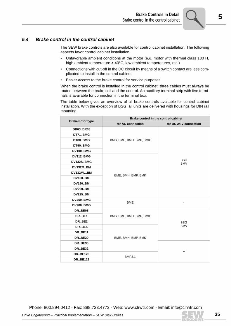
plicated to install in the control cabinet• Easier access to the brake control for service purposesWhen the brake control is installed in the control cabinet, three cables must always berouted between the brake coil and the control. An auxiliary terminal strip with five termi-nals is available for connection in the terminal box. The table below gives an overview of all brake controls available for control cabinetinstallation. With the exception of BSG, all units are delivered with housings for DIN railmounting.
Brakemotor typeBrake control in the control cabinet
for AC connection for DC 24 V connection
DR63..BR03
BMS, BME, BMH, BMP, BMK
BSGBMV
DT71..BMG
DT80..BMG
DT90..BMG
DV100..BMG
DV112..BMG
BME, BMH, BMP, BMK
DV132S..BMG
DV132M..BM
DV132ML..BM
DV160..BM
DV180..BM
DV200..BM
DV225..BM
DV250..BMGBME -
DV280..BMG
DR..BE05
BMS, BME, BMH, BMP, BMK
BSGBMV
DR..BE1
DR..BE2
DR..BE5
BME, BMH, BMP, BMK
DR..BE11
DR..BE20
DR..BE30
–DR..BE32
DR..BE120BMP3.1
DR..BE122
Drive Engineering – Practical Implementation – SEW Disk Brakes
Phone: 800.894.0412 - Fax: 888.723.4773 - Web: www.clrwtr.com - Email: info@
lt
35clrwtr.com
5 rake Controls in Detailrake control in the control cabinet
36
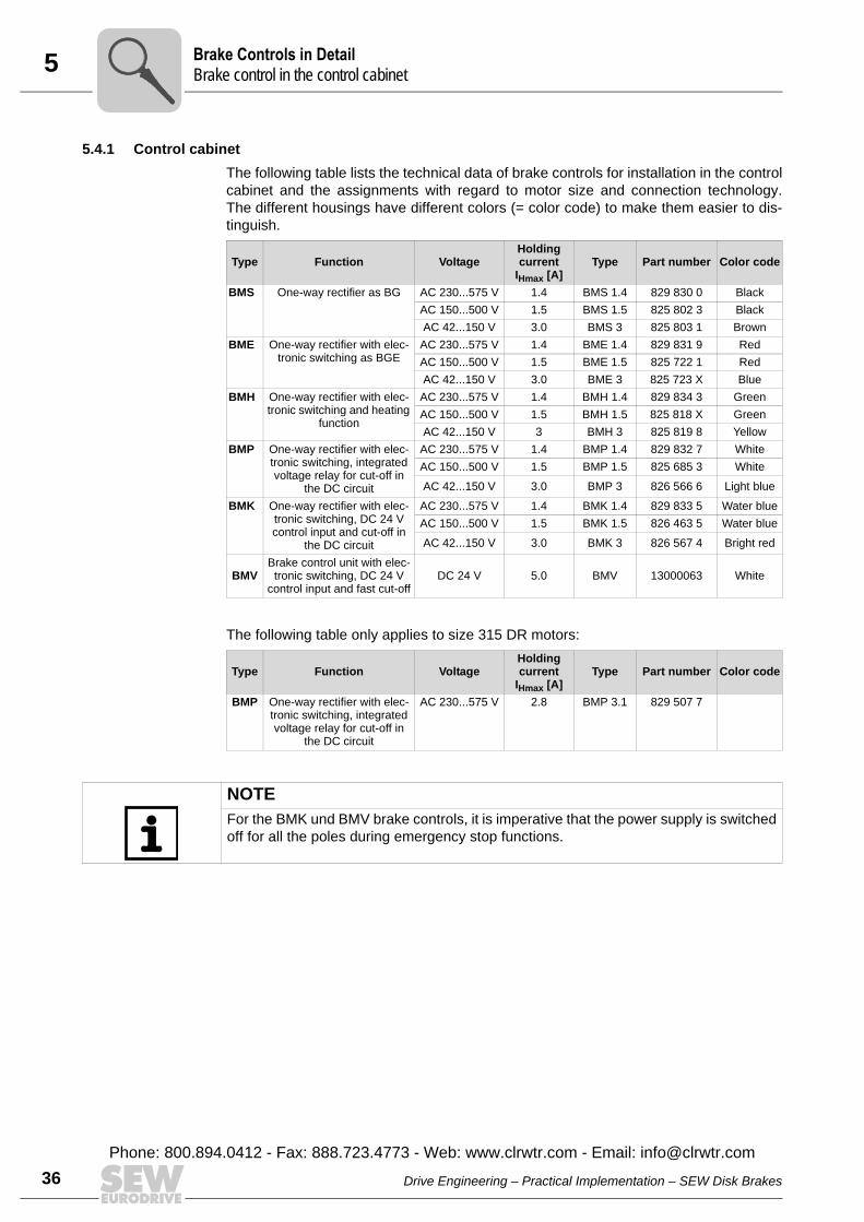
5.4.1 Control cabinetThe following table lists the technical data of brake controls for installation in the controlcabinet and the assignments with regard to motor size and connection technology.The different housings have different colors (= color code) to make them easier to dis-tinguish.
The following table only applies to size 315 DR motors:
Type Function VoltageHolding current
IHmax [A]Type Part number Color code
BMS One-way rectifier as BG AC 230...575 V 1.4 BMS 1.4 829 830 0 BlackAC 150...500 V 1.5 BMS 1.5 825 802 3 BlackAC 42...150 V 3.0 BMS 3 825 803 1 Brown
BME One-way rectifier with elec-tronic switching as BGE
AC 230...575 V 1.4 BME 1.4 829 831 9 RedAC 150...500 V 1.5 BME 1.5 825 722 1 RedAC 42...150 V 3.0 BME 3 825 723 X Blue
BMH One-way rectifier with elec-tronic switching and heating
function
AC 230...575 V 1.4 BMH 1.4 829 834 3 GreenAC 150...500 V 1.5 BMH 1.5 825 818 X GreenAC 42...150 V 3 BMH 3 825 819 8 Yellow
BMP One-way rectifier with elec-tronic switching, integrated voltage relay for cut-off in
the DC circuit
AC 230...575 V 1.4 BMP 1.4 829 832 7 WhiteAC 150...500 V 1.5 BMP 1.5 825 685 3 WhiteAC 42...150 V 3.0 BMP 3 826 566 6 Light blue
BMK One-way rectifier with elec-tronic switching, DC 24 V control input and cut-off in
the DC circuit
AC 230...575 V 1.4 BMK 1.4 829 833 5 Water blueAC 150...500 V 1.5 BMK 1.5 826 463 5 Water blueAC 42...150 V 3.0 BMK 3 826 567 4 Bright red
BMVBrake control unit with elec-tronic switching, DC 24 V
control input and fast cut-offDC 24 V 5.0 BMV 13000063 White
Type Function VoltageHolding current
IHmax [A]Type Part number Color code
BMP One-way rectifier with elec-tronic switching, integrated voltage relay for cut-off in
the DC circuit
AC 230...575 V 2.8 BMP 3.1 829 507 7
NOTEFor the BMK und BMV brake controls, it is imperative that the power supply is switchedoff for all the poles during emergency stop functions.
BB
Drive Engineering – Practical Implementation – SEW Disk Brakes
Phone: 800.894.0412 - Fax: 888.723.4773 - Web: www.clrwtr.com - Email: [email protected]
5Brake Controls in DetaiBrake control in the wiring space
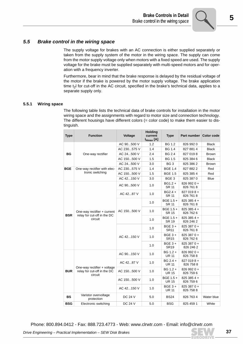
5.5 Brake control in the wiring spaceThe supply voltage for brakes with an AC connection is either supplied separately ortaken from the supply system of the motor in the wiring space. The supply can comefrom the motor supply voltage only when motors with a fixed speed are used. The supplyvoltage for the brake must be supplied separately with multi-speed motors and for oper-ation with a frequency inverter.Furthermore, bear in mind that the brake response is delayed by the residual voltage ofthe motor if the brake is powered by the motor supply voltage. The brake applicationtime t2l for cut-off in the AC circuit, specified in the brake’s technical data, applies to aseparate supply only.
5.5.1 Wiring spaceThe following table lists the technical data of brake controls for installation in the motorwiring space and the assignments with regard to motor size and connection technology.The different housings have different colors (= color code) to make them easier to dis-tinguish.
Type Function VoltageHolding current
IHmax [A]Type Part number Color code
BG One-way rectifier
AC 90...500 V 1.2 BG 1.2 826 992 0 BlackAC 230...575 V 1.4 BG 1.4 827 881 4 BlackAC 24...500 V 2.4 BG 2.4 827 019 8 Brown
AC 150...500 V 1.5 BG 1.5 825 384 6 BlackAC 24...500 V 3.0 BG 3 825 386 2 Brown
BGE One-way rectifier with elec-tronic switching
AC 230...575 V 1.4 BGE 1.4 827 882 2 RedAC 150...500 V 1.5 BGE 1.5 825 385 4 RedAC 42...150 V 3.0 BGE 3 825 387 0 Blue
BSROne-way rectifier + current relay for cut-off in the DC
circuit
AC 90...500 V 1.0 BG1.2 + SR 11
826 992 0 + 826 761 8
AC 42...87 V 1.0 BG2.4 + SR 11
827 019 8 + 826 761 8
AC 150...500 V
1.0 BGE 1.5 + SR 11
825 385 4 + 826 761 8
1.0 BGE 1.5 + SR 15
825 385 4 + 826 762 6
1.0 BGE 1.5 + SR 19
825 385 4 + 826 246 2
AC 42...150 V
1.0 BGE 3 + SR11
825 387 0 + 826 761 8
1.0 BGE 3 + SR15
825 387 0 + 826 762 6
1.0 BGE 3 + SR19
825 387 0 + 826 246 2
BUROne-way rectifier + voltage relay for cut-off in the DC
circuit
AC 90...150 V 1.0 BG 1.2 + UR 11
826 992 0 + 826 758 8
AC 42...87 V 1.0 BG 2.4 + UR 11
827 019 8 + 826 758 8
AC 150...500 V 1.0 BG 1.2 + UR 15
826 992 0 + 826 759 6
AC 150...500 V 1.0 BGE 1.5 + UR 15
825 385 4 + 826 759 6
AC 42...150 V 1.0 BGE 3 + UR 11
825 387 0 + 826 758 8
BS Varistor overvoltage protection DC 24 V 5.0 BS24 826 763 4 Water blue
BSG Electronic switching DC 24 V 5.0 BSG 825 459 1 White
Drive Engineering – Practical Implementation – SEW Disk Brakes
Phone: 800.894.0412 - Fax: 888.723.4773 - Web: www.clrwtr.com - Email: info@
l
37clrwtr.com

5 rake Controls in Detailulti-motor operation of brakemotors
38
The following table only applies to DR motors of the size 315:
5.6 Multi-motor operation of brakemotorsBrakes must be switched at the same time in multi-motor operation and must also applytogether when a fault occurs in one brake.Simultaneous switching can be achieved by connecting any particular group of brakesin parallel to one brake control.When several brakes are connected in parallel to the same brake rectifier, the totalof all the operating currents must not exceed the rated current of the brakecontrol.
Type Function VoltageHolding current
IHmax [A]Type Part number Color code
BMP One-way rectifier with elec-tronic switching, integrated voltage relay for cut-off in
the DC circuit
AC 230...575 V 2.8 BMP 3.1 829 507 7
NOTICEDefective brake rectifier Device damage• In case of a fault in one brake, switch off all brakes.
BM
Drive Engineering – Practical Implementation – SEW Disk Brakes
Phone: 800.894.0412 - Fax: 888.723.4773 - Web: www.clrwtr.com - Email: [email protected]
6Project Planning InformationSelect the brake and the braking torque in accordance with the project planning data (motor
6 Project Planning InformationThe size of the brakemotor and its electrical connection must be selected carefully toensure the longest possible service life.When doing this, pay attention to the following points: • Select the brake and the braking torque in accordance with the project planning data
(motor selection)• Determine the brake voltage• Dimension and route the cable• Select brake contactor• Important design information• Motor protection switch if necessary to protect the brake coil
6.1 Select the brake and the braking torque in accordance with the project planning data (motor selection)
The mechanical components, brake type and braking torque are determined when thedrive motor is selected. The drive type, application areas and the standards that have tobe taken into account are also used for brake selection.Selection criteria:• AC motor with one speed/multi-speed motor • Speed-controlled AC motor with frequency inverter• Servomotor• Number of braking operations during service and number of emergency braking
operations• Working brake or holding brake• Level of braking torque (“soft braking”/“hard braking”) • Hoist applications• Minimum/maximum deceleration
Drive Engineering – Practical Implementation – SEW Disk Brakes
Phone: 800.894.0412 - Fax: 888.723.4773 - Web: www.clrwtr.com - Email: info@
39clrwtr.com
6 roject Planning Informationelect the brake and the braking torque in accordance with the project planning data (motor
40
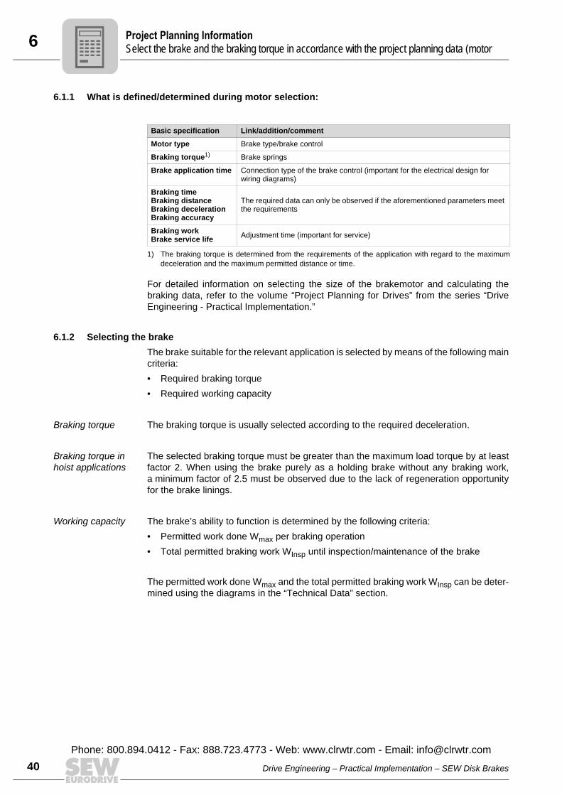
6.1.1 What is defined/determined during motor selection:
For detailed information on selecting the size of the brakemotor and calculating thebraking data, refer to the volume “Project Planning for Drives” from the series “DriveEngineering - Practical Implementation.”
6.1.2 Selecting the brakeThe brake suitable for the relevant application is selected by means of the following maincriteria:• Required braking torque• Required working capacity
Braking torque The braking torque is usually selected according to the required deceleration.
Braking torque in hoist applications
The selected braking torque must be greater than the maximum load torque by at leastfactor 2. When using the brake purely as a holding brake without any braking work,a minimum factor of 2.5 must be observed due to the lack of regeneration opportunityfor the brake linings.
Working capacity The brake’s ability to function is determined by the following criteria:• Permitted work done Wmax per braking operation• Total permitted braking work WInsp until inspection/maintenance of the brake
The permitted work done Wmax and the total permitted braking work WInsp can be deter-mined using the diagrams in the “Technical Data” section.
Basic specification Link/addition/comment
Motor type Brake type/brake control
Braking torque1)
1) The braking torque is determined from the requirements of the application with regard to the maximumdeceleration and the maximum permitted distance or time.
Brake springs
Brake application time Connection type of the brake control (important for the electrical design for wiring diagrams)
Braking timeBraking distanceBraking decelerationBraking accuracy
The required data can only be observed if the aforementioned parameters meet the requirements
Braking workBrake service life Adjustment time (important for service)
PS
Drive Engineering – Practical Implementation – SEW Disk Brakes
Phone: 800.894.0412 - Fax: 888.723.4773 - Web: www.clrwtr.com - Email: [email protected]
6Project Planning InformationSelect the brake and the braking torque in accordance with the project planning data (motor
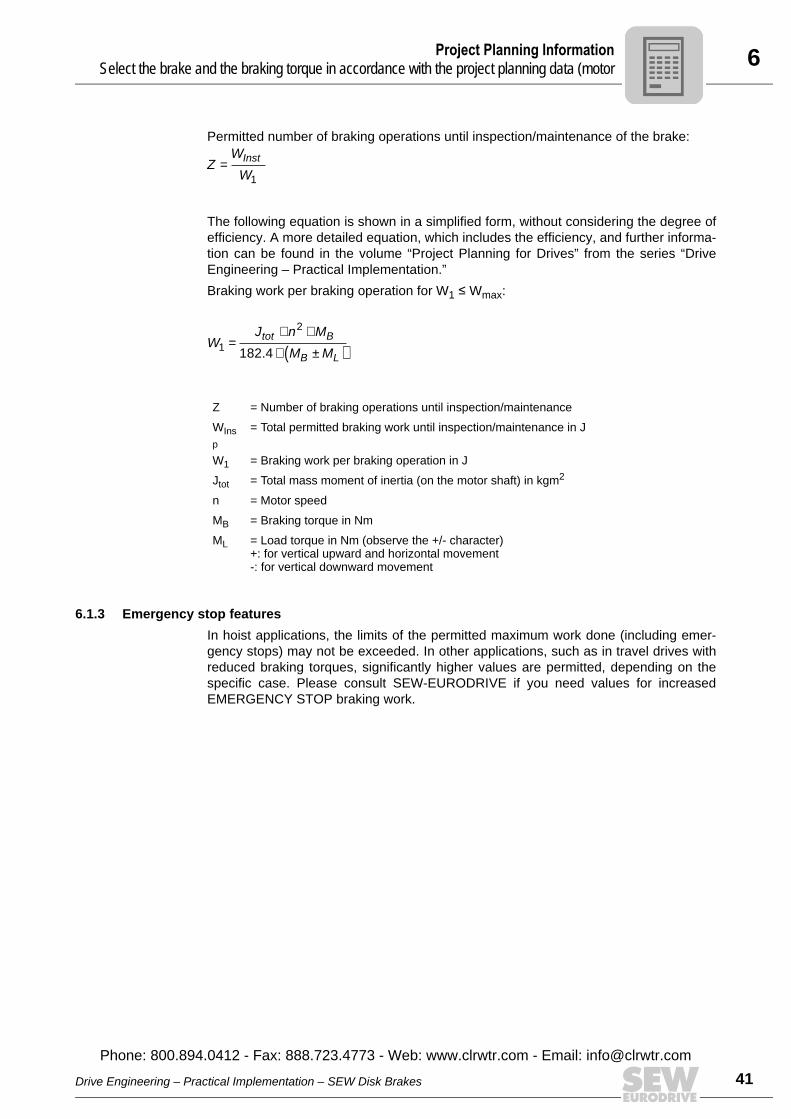
Permitted number of braking operations until inspection/maintenance of the brake:
The following equation is shown in a simplified form, without considering the degree ofefficiency. A more detailed equation, which includes the efficiency, and further informa-tion can be found in the volume “Project Planning for Drives” from the series “DriveEngineering – Practical Implementation.”Braking work per braking operation for W1 Â Wmax:
6.1.3 Emergency stop featuresIn hoist applications, the limits of the permitted maximum work done (including emer-gency stops) may not be exceeded. In other applications, such as in travel drives withreduced braking torques, significantly higher values are permitted, depending on thespecific case. Please consult SEW-EURODRIVE if you need values for increasedEMERGENCY STOP braking work.
Z = Number of braking operations until inspection/maintenanceWInsp
= Total permitted braking work until inspection/maintenance in J
W1 = Braking work per braking operation in JJtot = Total mass moment of inertia (on the motor shaft) in kgm2
n = Motor speedMB = Braking torque in NmML = Load torque in Nm (observe the +/- character)
+: for vertical upward and horizontal movement-: for vertical downward movement
ZW
WInst=
1
WJ n M
M Mtot B
B L1
2
182 4=
× ×× ±( ).
Drive Engineering – Practical Implementation – SEW Disk Brakes
Phone: 800.894.0412 - Fax: 888.723.4773 - Web: www.clrwtr.com - Email: info@
41clrwtr.com
6 roject Planning Informationelect the brake and the braking torque in accordance with the project planning data (motor
42
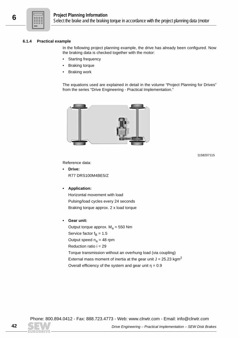
6.1.4 Practical exampleIn the following project planning example, the drive has already been configured. Nowthe braking data is checked together with the motor:• Starting frequency• Braking torque• Braking work
The equations used are explained in detail in the volume “Project Planning for Drives”from the series “Drive Engineering - Practical Implementation.”
Reference data:• Drive:
R77 DRS100M4BE5/Z
• Application:Horizontal movement with loadPulsing/load cycles every 24 secondsBraking torque approx. 2 x load torque
• Gear unit:Output torque approx. Ma = 550 NmService factor fB = 1.5Output speed na = 48 rpmReduction ratio i = 29Torque transmission without an overhung load (via coupling)External mass moment of inertia at the gear unit J = 25.23 kgm2
Overall efficiency of the system and gear unit η = 0.9
1158207115
PS
Drive Engineering – Practical Implementation – SEW Disk Brakes
Phone: 800.894.0412 - Fax: 888.723.4773 - Web: www.clrwtr.com - Email: [email protected]
6Project Planning InformationSelect the brake and the braking torque in accordance with the project planning data (motor
• Brakemotor:Rated power PN = 3 kWRated speed nN = 1400 rpmRated torque = 20.5 NmBraking torque MB = 40 NmMass moment of inertia JMot_BE = 0.0062 kgm2
Mass inertia of the flywheel fan JZ = 0.0135 kgm2
Cyclic duration factor CDF = 60%BGE type of rectifier
The permitted starting frequency of the motor must be determined before the brakingwork is calculated. This prevents the motor from attaining excessively high tempera-tures. The starting frequency is 24 seconds per pulsing for a cyclic duration factor of60%. This means that the motor starts up every 24 seconds and then brakes. For onehour, this means there is a starting frequency of:
The formula for calculating the starting frequency for horizontal movements is:
Now the factors that are still missing can be determined.Starting frequency Z0 (from catalog):Observe that the value Z0 must be reduced by a factor of 0.8 because of the flywheelfan.
ZP = Maximum permitted starting frequency in one hour
Z0 = Starting frequency per hour according to the catalog data
ML = Static load torque in Nm
MH = Acceleration torque of the motor in Nm
η = Efficiency
JM = Mass inertia of the motor in kgm2
JZ = Mass inertia of the flywheel fan in kgm2
JX = External mass inertia reduced on motor shaft in kgm2
KP = Calculation factor
Z shs hpresent = =3600
24150
1
Z Z
M
M
J JJ
J
KP
L
H
M ZX
M
P= ×−
×
+ +×0
1η
η
Zh h0 85001
0 8 68001= × =.
Drive Engineering – Practical Implementation – SEW Disk Brakes
Phone: 800.894.0412 - Fax: 888.723.4773 - Web: www.clrwtr.com - Email: info@
43clrwtr.com
6 roject Planning Informationelect the brake and the braking torque in accordance with the project planning data (motor
44
Static load torque ML (from the appendix):
Acceleration torque MH (from the catalog):
External mass moment of inertia JX from the appendix:
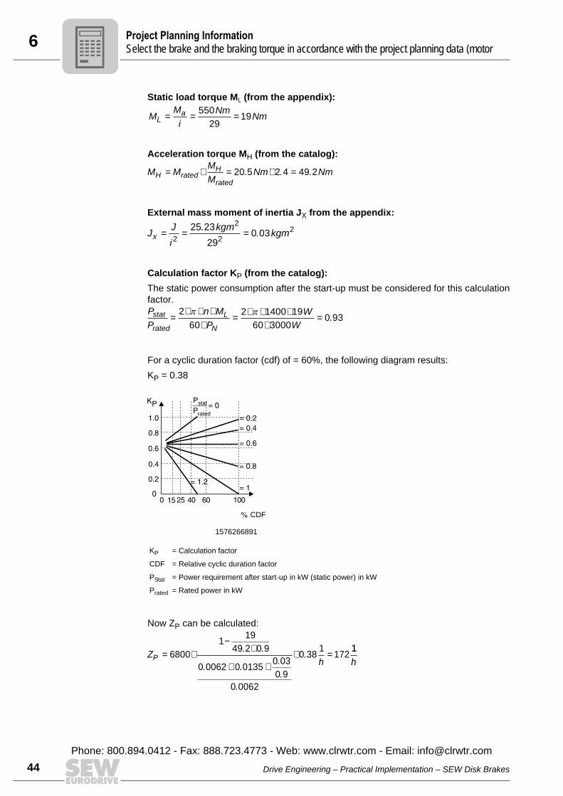
Calculation factor KP (from the catalog):The static power consumption after the start-up must be considered for this calculationfactor.
For a cyclic duration factor (cdf) of = 60%, the following diagram results:KP = 0.38
Now ZP can be calculated:
1576266891
KP = Calculation factor
CDF = Relative cyclic duration factor
PStat = Power requirement after start-up in kW (static power) in kW
Prated = Rated power in kW
MM
i
NmNmL
a= = =55029
19
M MMM
Nm NmH ratedH
rated= × = × =20 5 2 4 49 2. . .
J Ji
kgm kgmx = = =2
2
2
225 23
290 03
..
PP
n MP
WW
stat
rated
L
N=
× × ××
= × × ××
=2
60
2 1400 19
60 30000 93
π π.
CDF
rated
ZhP = ×
−×
+ +× =6800
119
49 2 0 9
0 0062 0 01350 03
0 9
0 0062
0 381
172. .
. ..
.
.
.11
h
PS
Drive Engineering – Practical Implementation – SEW Disk Brakes
Phone: 800.894.0412 - Fax: 888.723.4773 - Web: www.clrwtr.com - Email: [email protected]
6Project Planning InformationSelect the brake and the braking torque in accordance with the project planning data (motor
The following condition will be checked: The calculated maximum starting frequency must be higher than the one actuallypresent: ZP > ZpresentIn the example being discussed, this means that the condition is OK.
The motor can therefore maintain the required cycle time without overheating.
Now the brake itself will be checked. The BE5 brake can deliver up to 55 Nm of brakingtorque, but it is set to 40 Nm (ca. 2 x ML). The braking torque is therefore OK. Thencheck whether the resulting braking work per braking operation is not too high.The braking work is calculated as follows:
For vertical downwards, the result would be 876 J instead of 351 J; that is, 2.5 times asmuch!
Furthermore, the following condition must be met:The maximum braking work per braking operation must be greater that thebraking work actually occurring: Wmax > WB
The maximal permitted braking work can be determined based on the diagram forbraking work (see page 133) (diagram for rated speed, 1,500 rpm, curve BE5, Zpresent= 150 per hour).The following value can be derived from the diagram: Wmax = 2,200 J.This step satisfies the condition 2,200 J > 351 J.Therefore, the brake can withstand the load from the resulting braking work.
WB = Braking work per braking operation in J
MB = Braking torque in Nm
ML = Static load torque
η = Efficiency
JM = Mass inertia of the motor in kgm2
JZ = Mass inertia of the flywheel fan in kgm2
JX = External mass inertia, reduced on motor shaft, in kgm2
nM = Motor speed in rpm
182.5 = Conversion factor
172 1 150 1h h
>
WM
M MJ J J n
BB
B L
M Z X M=+ ×
×+ + × ×
ηη( )
.
2
182 5
NOTEIn the formula for braking work, a “+” is in the denominator of the first fraction. This onlyapplies for horizontal and rotary motion as well as upwards vertical movement. A “-”must be there for vertical movement downwards. The difference in the braking workrequired for vertically upwards movement and that for vertically downwards movementis very large.
Wmax = Maximum permitted braking work in J
W JB =+ ×
× + + × × =40
40 19 0 9
0 0062 0 0135 0 03 0 9 1400
182 5351
2
.
( . . . . )
.
Drive Engineering – Practical Implementation – SEW Disk Brakes
Phone: 800.894.0412 - Fax: 888.723.4773 - Web: www.clrwtr.com - Email: info@
45clrwtr.com
6 roject Planning Informationetermine the brake voltage
46
The service life of the brake lining until the next inspection/maintenance can now becalculated:
After about 4,940 hours, the maximum permitted air gap will be reached. The brake mustnow be set to the minimum air gap again as described in the operating instructions.
As an alternative to the available BE5 brake, it is possible under certain circumstancesto use the BE2 brake. For this, the required braking torque MB must be  20 Nm. Theirmaximum braking work Wmax (1,600 J) is sufficient if the peripheral conditions are thesame.
6.2 Determine the brake voltageThe brake voltage should always be selected on the basis of the available AC supplyvoltage or motor operating voltage. This means the user is always guaranteed the mostcost-effective installation for lower braking currents. In the case of multi-voltage versions for which the supply voltage has not been definedwhen the motor is purchased, the lower voltage must be selected in each case in orderto achieve feasible connection conditions when the brake control is installed in the ter-minal box.Extra-low voltages are often unavoidable for reasons of safety. However, they require aconsiderably greater investment in cables, switchgear, transformers/power-supply unitsas well as rectifiers and overvoltage protection (e.g. for direct DC 24 V supply) than isthe case for line voltage supply connections. With the exception of BG and BMS, the maximum current flowing when the brake isreleased is 8.5 times the holding current. The voltage at the brake coil must not dropbelow 90% of the rated voltage.
LW
W ZJ hJ
hBinst
B present=
×= × ×
× ×=260 10
351 1504938
6
NOTICEUncontrolled application of the brake. Potential damage to property.• Use larger cable cross sections. • Use high-capacity switchgear and transformers/power supplies.• Use a larger rectifier.
PD
Drive Engineering – Practical Implementation – SEW Disk Brakes
Phone: 800.894.0412 - Fax: 888.723.4773 - Web: www.clrwtr.com - Email: [email protected]
6Project Planning InformationDimensioning and routing the cable
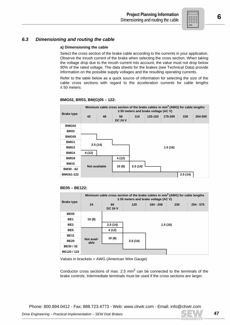
6.3 Dimensioning and routing the cablea) Dimensioning the cableSelect the cross section of the brake cable according to the currents in your application.Observe the inrush current of the brake when selecting the cross section. When takingthe voltage drop due to the inrush current into account, the value must not drop below90% of the rated voltage. The data sheets for the brakes (see Technical Data) provideinformation on the possible supply voltages and the resulting operating currents.Refer to the table below as a quick source of information for selecting the size of thecable cross sections with regard to the acceleration currents for cable lengths 50 meters.
BMG02, BR03, BM(G)05 – 122:
BE05 – BE122:
Values in brackets = AWG (American Wire Gauge)
Conductor cross sections of max. 2.5 mm2 can be connected to the terminals of thebrake controls. Intermediate terminals must be used if the cross sections are larger.
Brake type
Minimum cable cross section of the brake cables in mm2 (AWG) for cable lengths  50 meters and brake voltage (AC V)
42 48 56DC 24 V
110 125-153 175-200 230 254-500
BMG02
BR03
BMG05
BMG12.5 (14)
BMG2 1.5 (16)
BMG4 4 (12)
BMG8
Not available
4 (12)
BM1510 (8) 2.5 (14)
BM30 - 62
BMG61-122 2.5 (14)
Brake type
Minimum cable cross section of the brake cables in mm2 (AWG) for cable lengths  50 meters and brake voltage (AC V)
24 60DC 24 V
120 184 - 208 230 254 - 575
BE05
10 (8)BE1
BE2 2.5 (14) 1.5 (16)
BE5
Not avail-able
4 (12)
BE1110 (8)
2.5 (14)BE20
BE30 / 32
BE120 / 122
Drive Engineering – Practical Implementation – SEW Disk Brakes
Phone: 800.894.0412 - Fax: 888.723.4773 - Web: www.clrwtr.com - Email: info@
47clrwtr.com
6 roject Planning Informationelecting the brake contactor
48
b) Routing information: • Unless they are shielded, brake supply cables must always be routed separately
from other power cables with phased currents. • Ensure adequate equipotential bonding between the drive and the control cabinet
(for an example, see “EMC in Drive Engineering” from “Drive Engineering – PracticalImplementation”).
In particular, power cables with phased currents include:• Output cables from frequency inverters and servo controllers, soft-start units and
brake units• Supply cables to braking resistors
6.4 Selecting the brake contactor
The brake contactor for mains operation is selected as follows:• For the standard voltages AC 230 V or AC 400 V, a power contactor with a rated
power of 2.2 kW or 4 kW for AC-3 operation is selected.• The contactor is configured for DC-3 operation with DC 24 V.
When applications require cut-off in the DC and AC circuits for the brake, it is a goodidea to install SEW switchgear to perform this task.
6.4.1 Control cabinet installationBrake rectifiers (BMP, BMV and BMK), which perform the cut-off in the DC circuit inter-nally, have been specially designed for this purpose.
NOTICESwitching the DC voltage using unsuited contacts. Possible damage to the brake rectifier.• As switchgear for the brake voltage and the DC voltage cut-off, use either special
direct current contactors or adapted AC contactors in utilization category AC-3according to EN 60947-4-1.
PS
Drive Engineering – Practical Implementation – SEW Disk Brakes
Phone: 800.894.0412 - Fax: 888.723.4773 - Web: www.clrwtr.com - Email: [email protected]
6Project Planning InformationSelecting the brake contactor
6.4.2 Terminal box installationThe current and voltage relays (SR1x and UR1x), which are mounted directly on themotor, perform the same task.
Advantages compared to switch contacts:• Special contactors with four AC-3 contacts are not required.• The contact for the direct current separation is subjected to heavy loads and, there-
fore, to a high degree of wear. The electronic switches, however, function without anywear.
• Customers do not have to perform any additional wiring. Current and voltage relaysare delivered already wired from the factory. For BMP and BMK rectifiers, only thepower supply and the brake coils have to be connected.
• Two additional conductors between the motor and control cabinet are no longerrequired.
• No additional interference emission from contact bounce when the brake is cut-off inthe DC circuit.
6.4.3 Semi-conductor relaySemi-conductor relays with RC protection circuits are not suitable for switchingbrake rectifiers (with the exception of BG and BMS).
NOTICEBrake no longer releases. Device damage.• Brakes which are optimized for the accelerator function may not be operated with
the semiconductor RC suppressor circuit.
Drive Engineering – Practical Implementation – SEW Disk Brakes
Phone: 800.894.0412 - Fax: 888.723.4773 - Web: www.clrwtr.com - Email: info@
49clrwtr.com
6 roject Planning Informationportant design information
50
6.5 Important design informationa) EMC (Electromagnetic compatibility)SEW AC brakemotors comply with the relevant EMC generic standards when operatedin accordance with their designated use in continuous duty connected to mains power.Additional instructions in the frequency inverter documentation must also be taken intoaccount for operation with frequency inverters.The EMC instructions in the servo controller documentation must also be taken intoaccount for the operation of SEW servomotors with a brake.The instructions on laying cables (see page 47) must always be adhered to.
b) Connection typeThe electrical design team and, in particular the installation and startup personnel, mustbe given detailed information on the connection type and the intended brake function.Maintaining certain brake application times may be relevant to safety. The decision toimplement cut-off in the AC circuit or cut-off in the DC and AC circuits must be passedon clearly and unambiguously to the people undertaking the work. The brake reactiontimes t2I (see page 106 and following pages) for cut-off in the AC circuit apply only ifthere is a separate voltage supply. The times are longer if the brake is connected to theterminal board of the motor. BG and BGE are always supplied wired up for cut-off in theAC circuit in the terminal box. The blue wire from the brake coil must be moved fromterminal 5 of the rectifier to terminal 4 for cut-off in the AC and DC circuits. An additionalcontactor (SR/UR) must also be connected between terminals 4 and 5.
c) Maintenance intervalsThe time to maintenance is determined on the basis of the expected brake wear. Thisvalue is important for setting up the maintenance schedule for the machine to be usedby the customer’s service personnel (machine documentation).
d) Measuring principlesThe following points must be observed during service measurements on the brakes:The values for DC voltage specified in the data sheets only apply if brakes are suppliedwith DC voltage from an external source without an SEW brake control.Due to the fact that the freewheeling arm only extends over the coil section, the DCvoltage that can be measured during operation with the SEW-EURODRIVE brake con-trol is 10% to 20% lower than the normal one-way rectification when the freewheelingarm extends over the entire coil.
PIm
Drive Engineering – Practical Implementation – SEW Disk Brakes
Phone: 800.894.0412 - Fax: 888.723.4773 - Web: www.clrwtr.com - Email: [email protected]
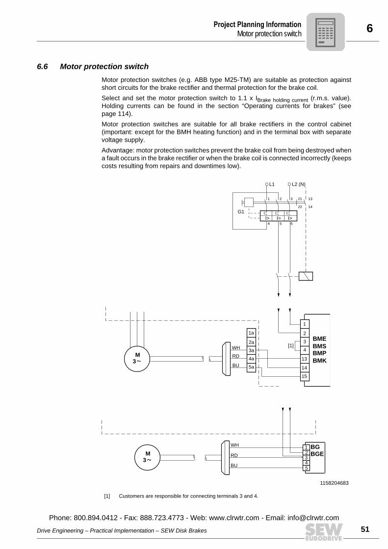
6Project Planning InformationMotor protection switch
6.6 Motor protection switchMotor protection switches (e.g. ABB type M25-TM) are suitable as protection againstshort circuits for the brake rectifier and thermal protection for the brake coil.Select and set the motor protection switch to 1.1 x IBrake holding current (r.m.s. value).Holding currents can be found in the section “Operating currents for brakes” (seepage 114).Motor protection switches are suitable for all brake rectifiers in the control cabinet(important: except for the BMH heating function) and in the terminal box with separatevoltage supply.Advantage: motor protection switches prevent the brake coil from being destroyed whena fault occurs in the brake rectifier or when the brake coil is connected incorrectly (keepscosts resulting from repairs and downtimes low).
1158204683
[1] Customers are responsible for connecting terminals 3 and 4.
BU
WH
RD3
M
1a
2a
5a
4a
3a
BME
BMS
BMP
BMK
1
2
13
14
15
4
3
5BU
WH
BGE
BG123RD
43
M
I>I>I>
1 2 3
4 5 6
21 13
22 14
G1
L1 L2 (N)
[1]
Drive Engineering – Practical Implementation – SEW Disk Brakes
Phone: 800.894.0412 - Fax: 888.723.4773 - Web: www.clrwtr.com - Email: info@
51clrwtr.com
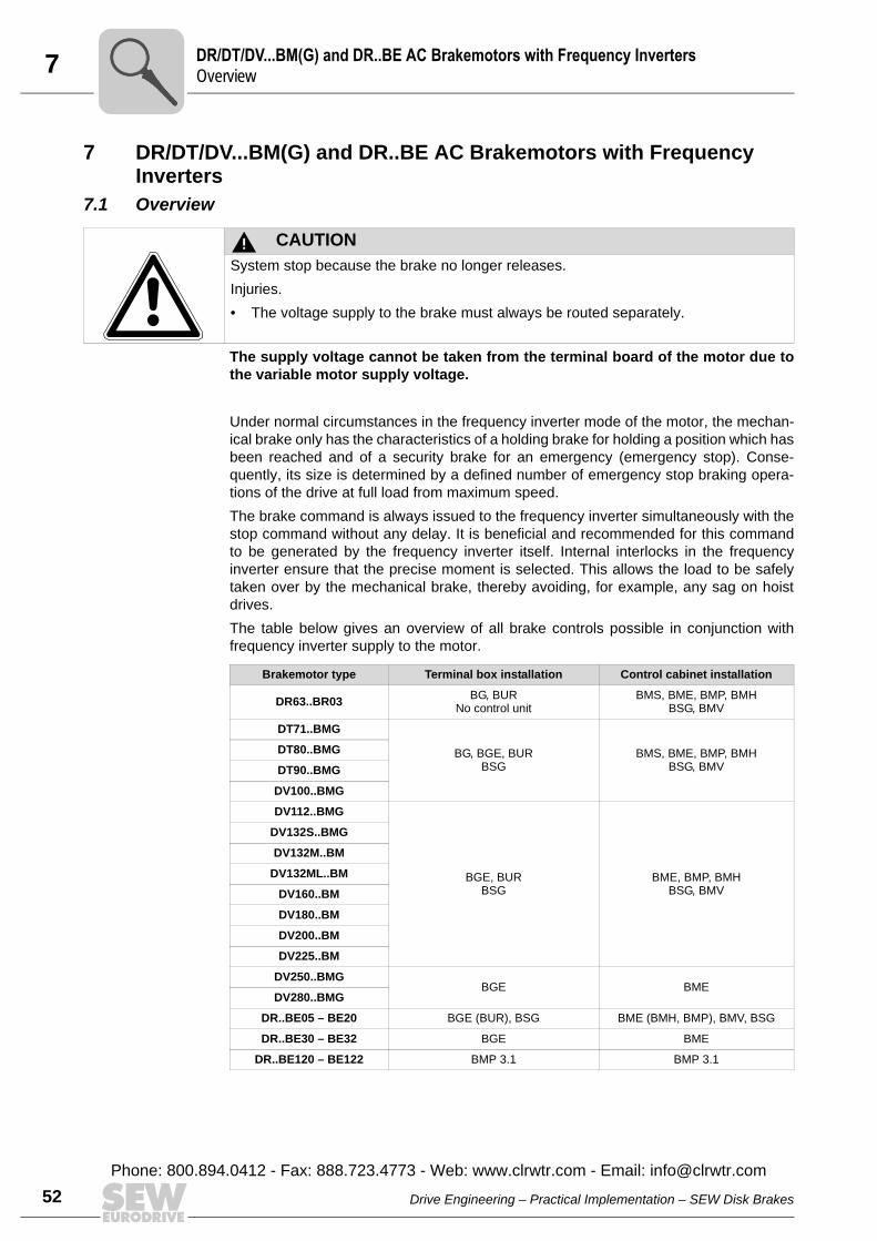
7 R/DT/DV...BM(G) and DR..BE AC Brakemotors with Frequency Invertersverview
52
7 DR/DT/DV...BM(G) and DR..BE AC Brakemotors with Frequency Inverters
7.1 Overview
The supply voltage cannot be taken from the terminal board of the motor due tothe variable motor supply voltage.
Under normal circumstances in the frequency inverter mode of the motor, the mechan-ical brake only has the characteristics of a holding brake for holding a position which hasbeen reached and of a security brake for an emergency (emergency stop). Conse-quently, its size is determined by a defined number of emergency stop braking opera-tions of the drive at full load from maximum speed. The brake command is always issued to the frequency inverter simultaneously with thestop command without any delay. It is beneficial and recommended for this commandto be generated by the frequency inverter itself. Internal interlocks in the frequencyinverter ensure that the precise moment is selected. This allows the load to be safelytaken over by the mechanical brake, thereby avoiding, for example, any sag on hoistdrives.The table below gives an overview of all brake controls possible in conjunction withfrequency inverter supply to the motor.
CAUTIONSystem stop because the brake no longer releases.Injuries.• The voltage supply to the brake must always be routed separately.
Brakemotor type Terminal box installation Control cabinet installation
DR63..BR03 BG, BURNo control unit
BMS, BME, BMP, BMHBSG, BMV
DT71..BMG
BG, BGE, BURBSG
BMS, BME, BMP, BMHBSG, BMV
DT80..BMG
DT90..BMG
DV100..BMG
DV112..BMG
BGE, BUR BSG
BME, BMP, BMHBSG, BMV
DV132S..BMG
DV132M..BM
DV132ML..BM
DV160..BM
DV180..BM
DV200..BM
DV225..BM
DV250..BMG BGE BME
DV280..BMG
DR..BE05 – BE20 BGE (BUR), BSG BME (BMH, BMP), BMV, BSG
DR..BE30 – BE32 BGE BME
DR..BE120 – BE122 BMP 3.1 BMP 3.1
DO
Drive Engineering – Practical Implementation – SEW Disk Brakes
Phone: 800.894.0412 - Fax: 888.723.4773 - Web: www.clrwtr.com - Email: [email protected]
7DR/DT/DV...BM(G) and DR..BE AC Brakemotors with Frequency InvertersAdditional documentation
7.2 Additional documentationFor further information and detailed technical data, refer to the following documentation:• “Gearmotors” catalog• “MOVIDRIVE® A” system manual and catalog• “MOVIDRIVE® B” system manual and catalog• “MOVITRAC® 07” system manual and catalog
Drive Engineering – Practical Implementation – SEW Disk Brakes
Phone: 800.894.0412 - Fax: 888.723.4773 - Web: www.clrwtr.com - Email: info@
53clrwtr.com

8 FS56..B, CMP..BP, CMD.. BP und CM..BR Servomotors with Brakeverview
54
8 DFS56..B, CMP..BP, CMD.. BP und CM..BR Servomotors with Brake8.1 Overview
DFS56..BBrake B of the DFS servomotor is a permanent magnet brake with a standard supplyvoltage of DC 24 V. It operates with an unchanging braking torque of 2.5 Nm (DFS56Mand DFS56L) and 5 Nm (DFS56H). The brake cannot be retrofitted and operates withouta brake rectifier or a brake control unit. The overvoltage protection must be implementedby the customer, for example using varistors. The brake can be used in all speedclasses.The following figure shows the wiring diagram:
CMP40..BP – CMP100..BP und CMD55..BP – CMD138..BP The BP brake of CMP and CMD servomotors is a spring-loaded brake with a standardsupply voltage of DC 24 V. It operates with an unchanging braking torque. The brakecannot be retrofitted and operates without a brake rectifier or a brake control unit.The overvoltage protection must be implemented by the customer, for example usingvaristors. The use of the brake is speed-dependant and must be considered when plan-ning the project. The following figures show the wiring diagrams:
1677465739
[1] Brake coil
1399195787
[1] Brake coil
1647935755
[1] Brake coil
BU
GNYE
RD
BK
BK
BK
U1BK
GNYE
BK V1
W1
U1
V1
W1
RD
BU
[1]
-
+
BK-/1
+/2SB10
SB11
D
C
B
A
3
1
4
YE
YE
BU
RD
BKU1
V1
D
C
B
A
3
1
4
BK
BK
GNYE GNYE
BK
BK
1
U
V
W3BK W1
[1]SB
SB1
V
W U
+
12
BKV
BK
W
BK
1
3
BK
BK
U
GNYE
-
V
WU
-+
1 2
RDV1
BUW1
GNYE
BKU1
YE
YE
[1]
SBB
DO
Drive Engineering – Practical Implementation – SEW Disk Brakes
Phone: 800.894.0412 - Fax: 888.723.4773 - Web: www.clrwtr.com - Email: [email protected]
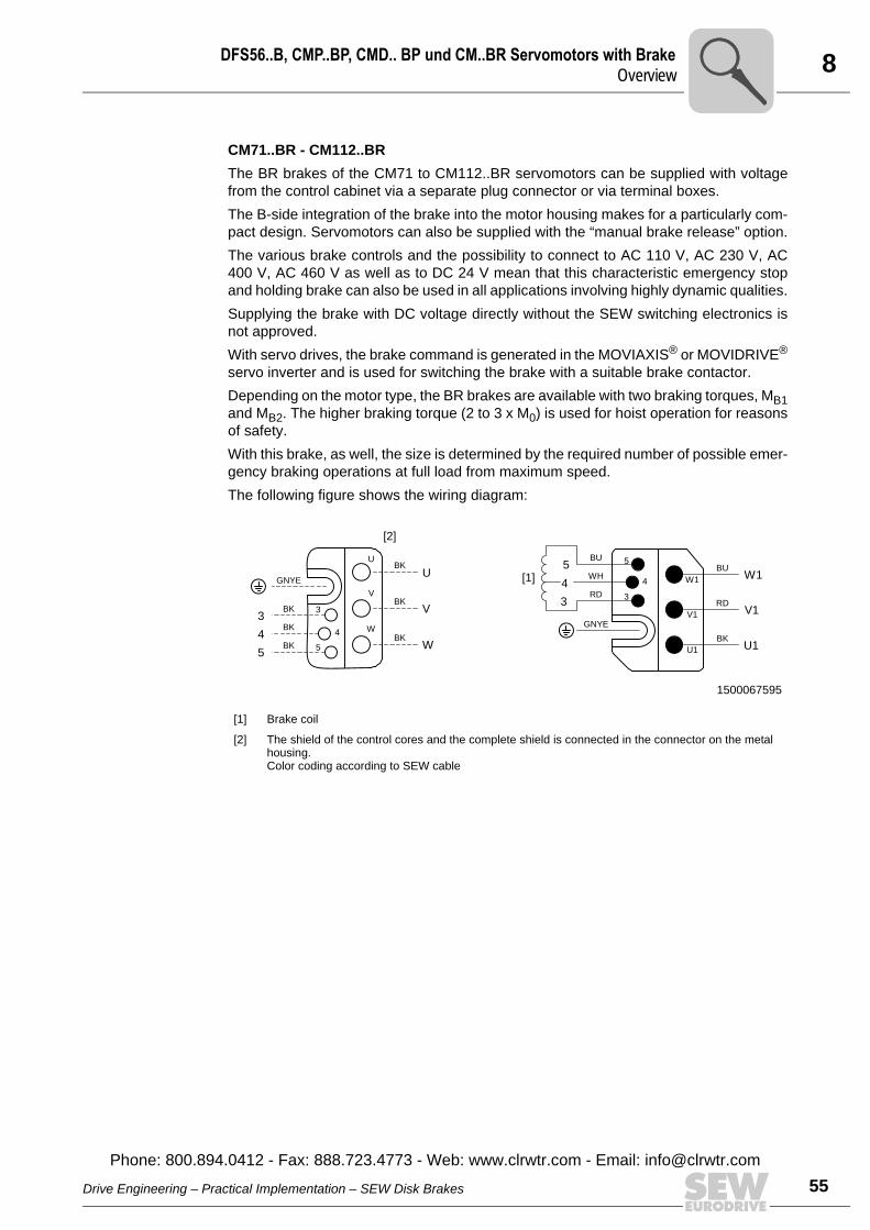
8DFS56..B, CMP..BP, CMD.. BP und CM..BR Servomotors with BrakeOverview
CM71..BR - CM112..BRThe BR brakes of the CM71 to CM112..BR servomotors can be supplied with voltagefrom the control cabinet via a separate plug connector or via terminal boxes.The B-side integration of the brake into the motor housing makes for a particularly com-pact design. Servomotors can also be supplied with the “manual brake release” option.The various brake controls and the possibility to connect to AC 110 V, AC 230 V, AC400 V, AC 460 V as well as to DC 24 V mean that this characteristic emergency stopand holding brake can also be used in all applications involving highly dynamic qualities.Supplying the brake with DC voltage directly without the SEW switching electronics isnot approved.With servo drives, the brake command is generated in the MOVIAXIS® or MOVIDRIVE®
servo inverter and is used for switching the brake with a suitable brake contactor.Depending on the motor type, the BR brakes are available with two braking torques, MB1and MB2. The higher braking torque (2 to 3 x M0) is used for hoist operation for reasonsof safety.With this brake, as well, the size is determined by the required number of possible emer-gency braking operations at full load from maximum speed.The following figure shows the wiring diagram:
1500067595
[1] Brake coil
[2] The shield of the control cores and the complete shield is connected in the connector on the metal housing.Color coding according to SEW cable
5
4
U1
V1
W1
3
BU
RD
BK
GNYE
BU
WH
RD
V1
U1
W15
4
3
BK
BK
BK
GNYE
BK
BK
BK
3
5
4
U
V
W
3
4
5
U
V
W
[1]
[2]
Drive Engineering – Practical Implementation – SEW Disk Brakes
Phone: 800.894.0412 - Fax: 888.723.4773 - Web: www.clrwtr.com - Email: info@
55clrwtr.com
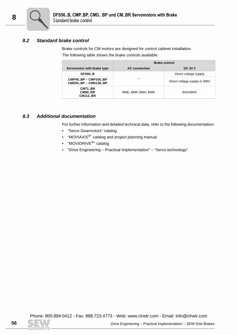
8 FS56..B, CMP..BP, CMD.. BP und CM..BR Servomotors with Braketandard brake control
56
8.2 Standard brake controlBrake controls for CM motors are designed for control cabinet installation.The following table shows the brake controls available:
8.3 Additional documentationFor further information and detailed technical data, refer to the following documentation:• “Servo Gearmotors” catalog• “MOVIAXIS®” catalog and project planning manual• “MOVIDRIVE®” catalog• “Drive Engineering – Practical Implementation” – “Servo technology”
Brake control
Servomotor with brake type AC connection DC 24 V
DFS56..B–
Direct voltage supply
CMP40..BP – CMP100..BPCMD55..BP – CMD138..BP Direct voltage supply or BMV
CM71..BRCM90..BRCM112..BR
BME, BMP, BMH, BMK BSG/BMV
DS
Drive Engineering – Practical Implementation – SEW Disk Brakes
Phone: 800.894.0412 - Fax: 888.723.4773 - Web: www.clrwtr.com - Email: [email protected]
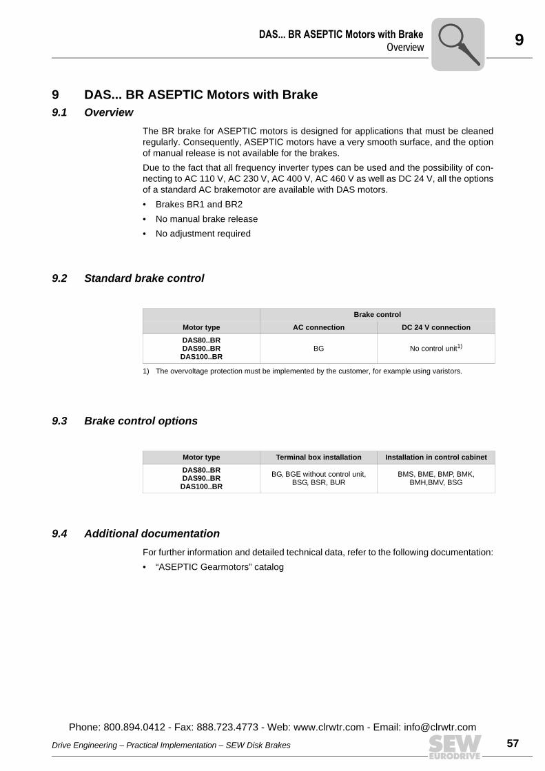
9DAS... BR ASEPTIC Motors with BrakeOverview
9 DAS... BR ASEPTIC Motors with Brake9.1 Overview
The BR brake for ASEPTIC motors is designed for applications that must be cleanedregularly. Consequently, ASEPTIC motors have a very smooth surface, and the optionof manual release is not available for the brakes.Due to the fact that all frequency inverter types can be used and the possibility of con-necting to AC 110 V, AC 230 V, AC 400 V, AC 460 V as well as DC 24 V, all the optionsof a standard AC brakemotor are available with DAS motors.• Brakes BR1 and BR2 • No manual brake release• No adjustment required
9.2 Standard brake control
9.3 Brake control options
9.4 Additional documentationFor further information and detailed technical data, refer to the following documentation:• “ASEPTIC Gearmotors” catalog
Brake control
Motor type AC connection DC 24 V connection
DAS80..BRDAS90..BR
DAS100..BRBG No control unit1)
1) The overvoltage protection must be implemented by the customer, for example using varistors.
Motor type Terminal box installation Installation in control cabinet
DAS80..BRDAS90..BR
DAS100..BRBG, BGE without control unit,
BSG, BSR, BURBMS, BME, BMP, BMK,
BMH,BMV, BSG
Drive Engineering – Practical Implementation – SEW Disk Brakes
Phone: 800.894.0412 - Fax: 888.723.4773 - Web: www.clrwtr.com - Email: info@
57clrwtr.com
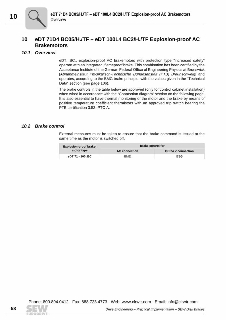
10 DT 71D4 BC05/H./TF – eDT 100L4 BC2/H./TF Explosion-proof AC Brakemotorsverview
58
10 eDT 71D4 BC05/H./TF – eDT 100L4 BC2/H./TF Explosion-proof AC Brakemotors
10.1 OvervieweDT...BC.. explosion-proof AC brakemotors with protection type “increased safety”operate with an integrated, flameproof brake. This combination has been certified by theAcceptance Institute of the German Federal Office of Engineering Physics at Brunswick[Abnahmeinstitut Physikalisch-Technische Bundesanstalt (PTB) Braunschweig] andoperates, according to the BMG brake principle, with the values given in the “TechnicalData” section (see page 106).The brake controls in the table below are approved (only for control cabinet installation)when wired in accordance with the “Connection diagram” section on the following page.It is also essential to have thermal monitoring of the motor and the brake by means ofpositive temperature coefficient thermistors with an approved trip switch bearing thePTB certification 3.53 -PTC A.
10.2 Brake controlExternal measures must be taken to ensure that the brake command is issued at thesame time as the motor is switched off.
Explosion-proof brake-motor type
Brake control for
AC connection DC 24 V connection
eDT 71 - 100..BC BME BSG
eO
Drive Engineering – Practical Implementation – SEW Disk Brakes
Phone: 800.894.0412 - Fax: 888.723.4773 - Web: www.clrwtr.com - Email: [email protected]
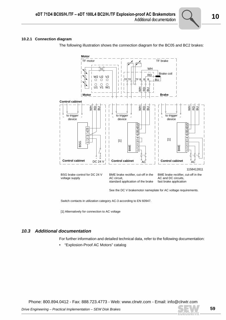
10eDT 71D4 BC05/H./TF – eDT 100L4 BC2/H./TF Explosion-proof AC BrakemotorsAdditional documentation
10.2.1 Connection diagram The following illustration shows the connection diagram for the BC05 and BC2 brakes:
10.3 Additional documentationFor further information and detailed technical data, refer to the following documentation:• “Explosion-Proof AC Motors” catalog
1158412811
BSG brake control for DC 24 V voltage supply
BME brake rectifier, cut-off in the AC circuit, standard application of the brake
BME brake rectifier, cut-off in the AC and DC circuits, fast brake application
See the DC V brakemotor nameplate for AC voltage requirements.
Switch contacts in utilization category AC-3 according to EN 60947.
[1] Alternatively for connection to AC voltage
BS
G
BM
E
ACDC 24 VControl cabinet Control cabinet
to trigger
device
to trigger
device
Brake coil
Brake
TF motor TF brake
WH
WH
RD
RD
BU
WH
RD
BU
WH
RD
BU
BU
TF
TF BBBTFTFW2 U2 V2
U1 V1 W1
Motor
15
12
34
5
14
13
43
21 B
ME
ACControl cabinet
to trigger
device
WH
RD
BU
15
14
13
43
21
- +
Motor
Control cabinet
[1] [1]
Drive Engineering – Practical Implementation – SEW Disk Brakes
Phone: 800.894.0412 - Fax: 888.723.4773 - Web: www.clrwtr.com - Email: info@
59clrwtr.com
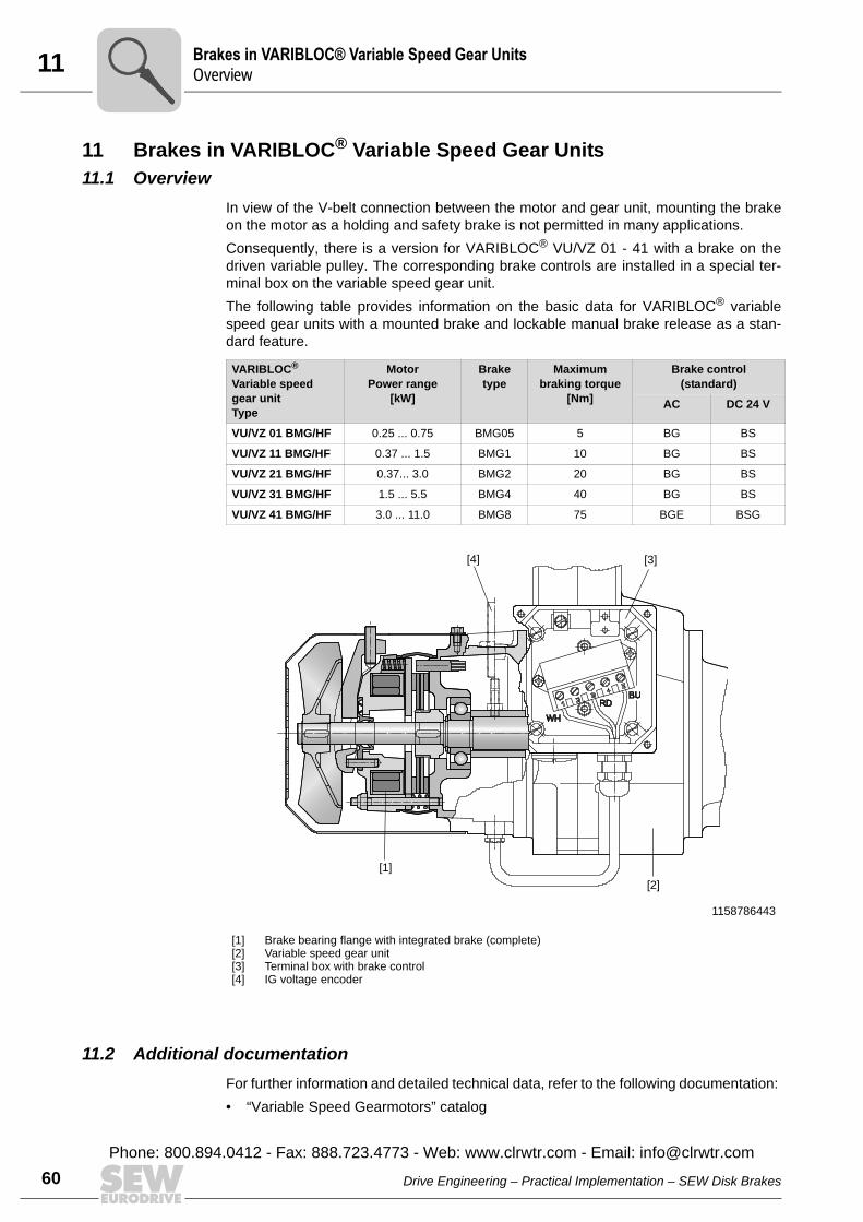
11 rakes in VARIBLOC® Variable Speed Gear Unitsverview
60
11 Brakes in VARIBLOC® Variable Speed Gear Units11.1 Overview
In view of the V-belt connection between the motor and gear unit, mounting the brakeon the motor as a holding and safety brake is not permitted in many applications.Consequently, there is a version for VARIBLOC® VU/VZ 01 - 41 with a brake on thedriven variable pulley. The corresponding brake controls are installed in a special ter-minal box on the variable speed gear unit.The following table provides information on the basic data for VARIBLOC® variablespeed gear units with a mounted brake and lockable manual brake release as a stan-dard feature.
11.2 Additional documentationFor further information and detailed technical data, refer to the following documentation: • “Variable Speed Gearmotors” catalog
VARIBLOC®
Variable speed gear unitType
MotorPower range
[kW]
Brake type
Maximum braking torque
[Nm]
Brake control(standard)
AC DC 24 V
VU/VZ 01 BMG/HF 0.25 ... 0.75 BMG05 5 BG BS
VU/VZ 11 BMG/HF 0.37 ... 1.5 BMG1 10 BG BS
VU/VZ 21 BMG/HF 0.37... 3.0 BMG2 20 BG BS
VU/VZ 31 BMG/HF 1.5 ... 5.5 BMG4 40 BG BS
VU/VZ 41 BMG/HF 3.0 ... 11.0 BMG8 75 BGE BSG
1158786443
[1][2][3][4]
Brake bearing flange with integrated brake (complete)Variable speed gear unitTerminal box with brake controlIG voltage encoder
[4] [3]
[1][2]
BO
Drive Engineering – Practical Implementation – SEW Disk Brakes
Phone: 800.894.0412 - Fax: 888.723.4773 - Web: www.clrwtr.com - Email: [email protected]
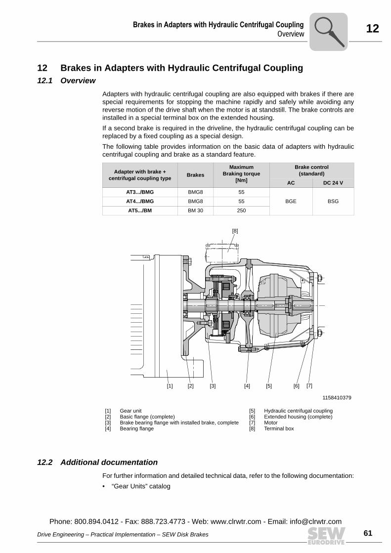
12Brakes in Adapters with Hydraulic Centrifugal CouplingOverview
12 Brakes in Adapters with Hydraulic Centrifugal Coupling12.1 Overview
Adapters with hydraulic centrifugal coupling are also equipped with brakes if there arespecial requirements for stopping the machine rapidly and safely while avoiding anyreverse motion of the drive shaft when the motor is at standstill. The brake controls areinstalled in a special terminal box on the extended housing. If a second brake is required in the driveline, the hydraulic centrifugal coupling can bereplaced by a fixed coupling as a special design.The following table provides information on the basic data of adapters with hydrauliccentrifugal coupling and brake as a standard feature.
12.2 Additional documentationFor further information and detailed technical data, refer to the following documentation:• “Gear Units” catalog
Adapter with brake +centrifugal coupling type Brakes
Maximum Braking torque
[Nm]
Brake control(standard)
AC DC 24 V
AT3.../BMG BMG8 55
BGE BSGAT4.../BMG BMG8 55
AT5.../BM BM 30 250
1158410379
[1][2][3][4]
Gear unitBasic flange (complete)Brake bearing flange with installed brake, completeBearing flange
[5][6][7][8]
Hydraulic centrifugal couplingExtended housing (complete)MotorTerminal box
[2] [3] [4] [5] [6] [7][1]
[8]
Drive Engineering – Practical Implementation – SEW Disk Brakes
Phone: 800.894.0412 - Fax: 888.723.4773 - Web: www.clrwtr.com - Email: info@
61clrwtr.com
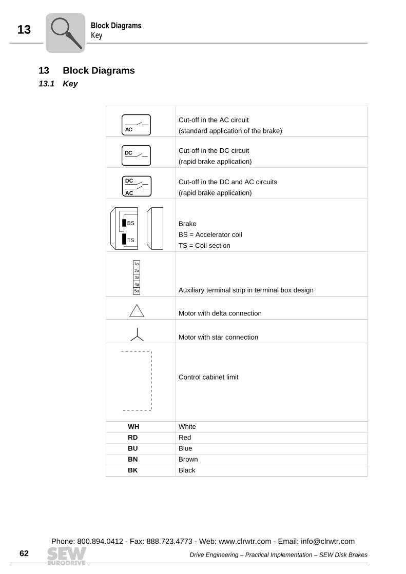
13 lock Diagramsey
62
13 Block Diagrams13.1 Key
Cut-off in the AC circuit (standard application of the brake)
Cut-off in the DC circuit(rapid brake application)
Cut-off in the DC and AC circuits(rapid brake application)
BrakeBS = Accelerator coilTS = Coil section
Auxiliary terminal strip in terminal box design
Motor with delta connection
Motor with star connection
Control cabinet limit
WH WhiteRD RedBU BlueBN BrownBK Black
AC
DC
AC
DC
BS
TS
1a
2a
5a
4a
3a
BK
Drive Engineering – Practical Implementation – SEW Disk Brakes
Phone: 800.894.0412 - Fax: 888.723.4773 - Web: www.clrwtr.com - Email: [email protected]
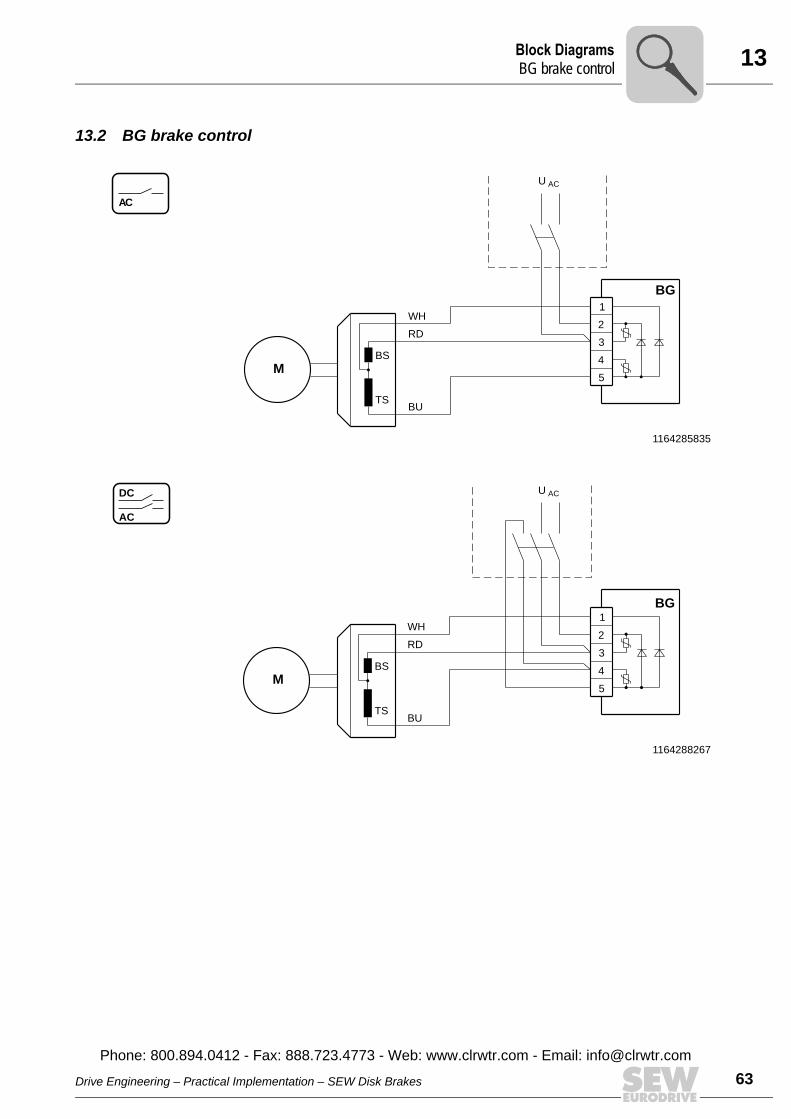
13Block DiagramsBG brake contro
13.2 BG brake control
1164285835
1164288267
AC
M4
1
3
2
TS
BS
BU
BG
RD
WH
ACU
5
AC
DC AC
BG
RD
WH
U
5
4
1
3
2
BU
M
TS
BS
Drive Engineering – Practical Implementation – SEW Disk Brakes
Phone: 800.894.0412 - Fax: 888.723.4773 - Web: www.clrwtr.com - Email: info@
l
63clrwtr.com
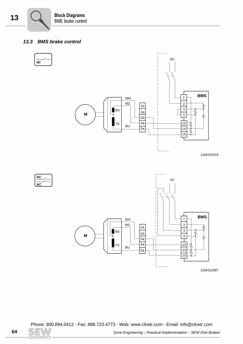
13 lock DiagramsMS brake control
64
13.3 BMS brake control
1164315019
1164312587
AC
BU
AC
WH
RD1a
2a
5a
4a
3a
BMS1
2
13
14
15
4
3
M
TS
BS
AC
DC
BU
AC
WH
RD1a
2a
5a
4a
3aM
TS
BS
BMS1
2
13
14
15
4
3
BB
Drive Engineering – Practical Implementation – SEW Disk Brakes
Phone: 800.894.0412 - Fax: 888.723.4773 - Web: www.clrwtr.com - Email: [email protected]
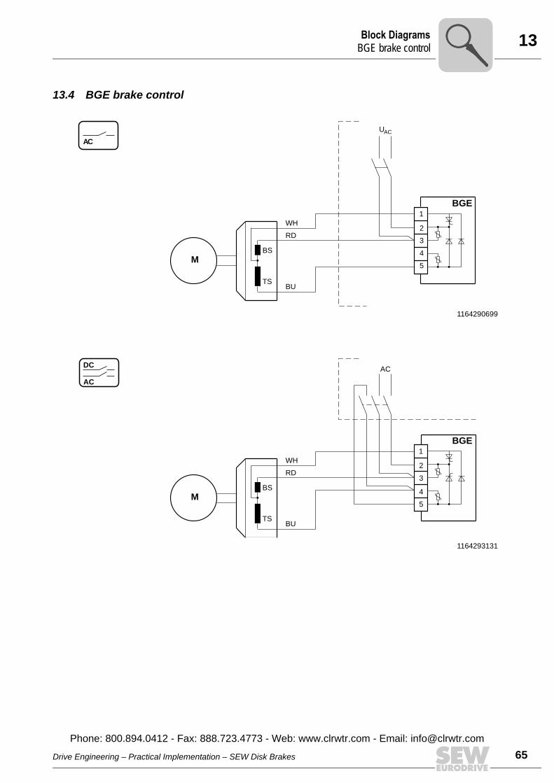
13Block DiagramsBGE brake contro
13.4 BGE brake control
1164290699
1164293131
AC
1
2
5
4
3
BU
WH
RD
BGE
ACU
M
TS
BS
AC
DC
1
2
5
4
3
BU
WH
RD
BGE
AC
M
TS
BS
Drive Engineering – Practical Implementation – SEW Disk Brakes
Phone: 800.894.0412 - Fax: 888.723.4773 - Web: www.clrwtr.com - Email: info@
l
65clrwtr.com

13 lock DiagramsME brake control
66
13.5 BME brake control
1164297995
1164295563
AC
BU
UAC
WH
RD1a
2a
5a
4a
3a
BME1
2
13
14
15
4
3M
TS
BS
AC
DC
BU
AC
WH
RD1a
2a
5a
4a
3a
BME1
2
13
14
15
4
3M
TS
BS
BB
Drive Engineering – Practical Implementation – SEW Disk Brakes
Phone: 800.894.0412 - Fax: 888.723.4773 - Web: www.clrwtr.com - Email: [email protected]
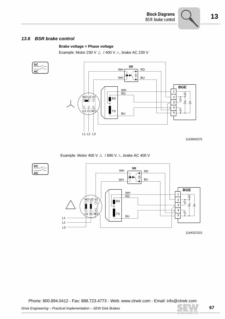
13Block DiagramsBSR brake contro
13.6 BSR brake controlBrake voltage = Phase voltageExample: Motor 230 V Ö / 400 V Õ, brake AC 230 V
1163992075
Example: Motor 400 V Ö / 690 V Õ, brake AC 400 V
1164322315
AC
DC
BU
WH
WH
WH
BU
RD
RD
TS
BS
1
2
5
4
3
BGE
V2U2
SR
L1
V1U1 W1
W2
L3L2
AC
DC
WH
WH
BU
RD
V2U2
SR
L1
V1U1 W1
W2
L3
L2
1
2
5
4
3
BGE
BU
WHRD
TS
BS
Drive Engineering – Practical Implementation – SEW Disk Brakes
Phone: 800.894.0412 - Fax: 888.723.4773 - Web: www.clrwtr.com - Email: info@
l
67clrwtr.com
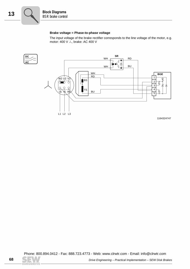
13 lock DiagramsSR brake control
68
Brake voltage = Phase-to-phase voltageThe input voltage of the brake rectifier corresponds to the line voltage of the motor, e.g.motor: 400 V Õ, brake: AC 400 V
1164324747
AC
DC
V2U2
SR
V1
RD
U1 W1
W2
BU
WH
WH
L1 L3L2
1
2
5
4
3
BGE
BU
WH
RD
TS
BS
BB
Drive Engineering – Practical Implementation – SEW Disk Brakes
Phone: 800.894.0412 - Fax: 888.723.4773 - Web: www.clrwtr.com - Email: [email protected]
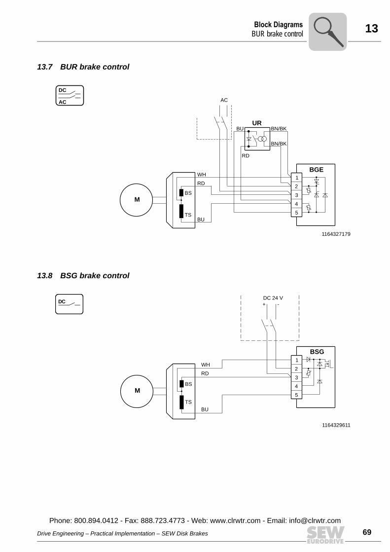
13Block DiagramsBUR brake contro
13.7 BUR brake control
13.8 BSG brake control
1164327179
AC
DC
BGE
UR
RD
RD
WH
AC
5
4
1
3
2
BU
BU BN/BK
BN/BK
M
TS
BS
1164329611
DC
M4
1
3
2
TS
BS
BU
BSG
RD
WH
DC 24 V
+ -
5
Drive Engineering – Practical Implementation – SEW Disk Brakes
Phone: 800.894.0412 - Fax: 888.723.4773 - Web: www.clrwtr.com - Email: info@
l
69clrwtr.com

13 lock DiagramsMP brake control
70
13.9 BMP brake control
1164307723
1164310155
AC
DC
BU
AC
WH
RD1a
2a
5a
4a
3aM
TS
BS
1
2
13
14
15
4
3
BMP
AC
BU
AC
WH
RD1a
2a
5a
4a
3aM
TS
BS
1
2
13
14
15
4
3
BMP
BB
Drive Engineering – Practical Implementation – SEW Disk Brakes
Phone: 800.894.0412 - Fax: 888.723.4773 - Web: www.clrwtr.com - Email: [email protected]
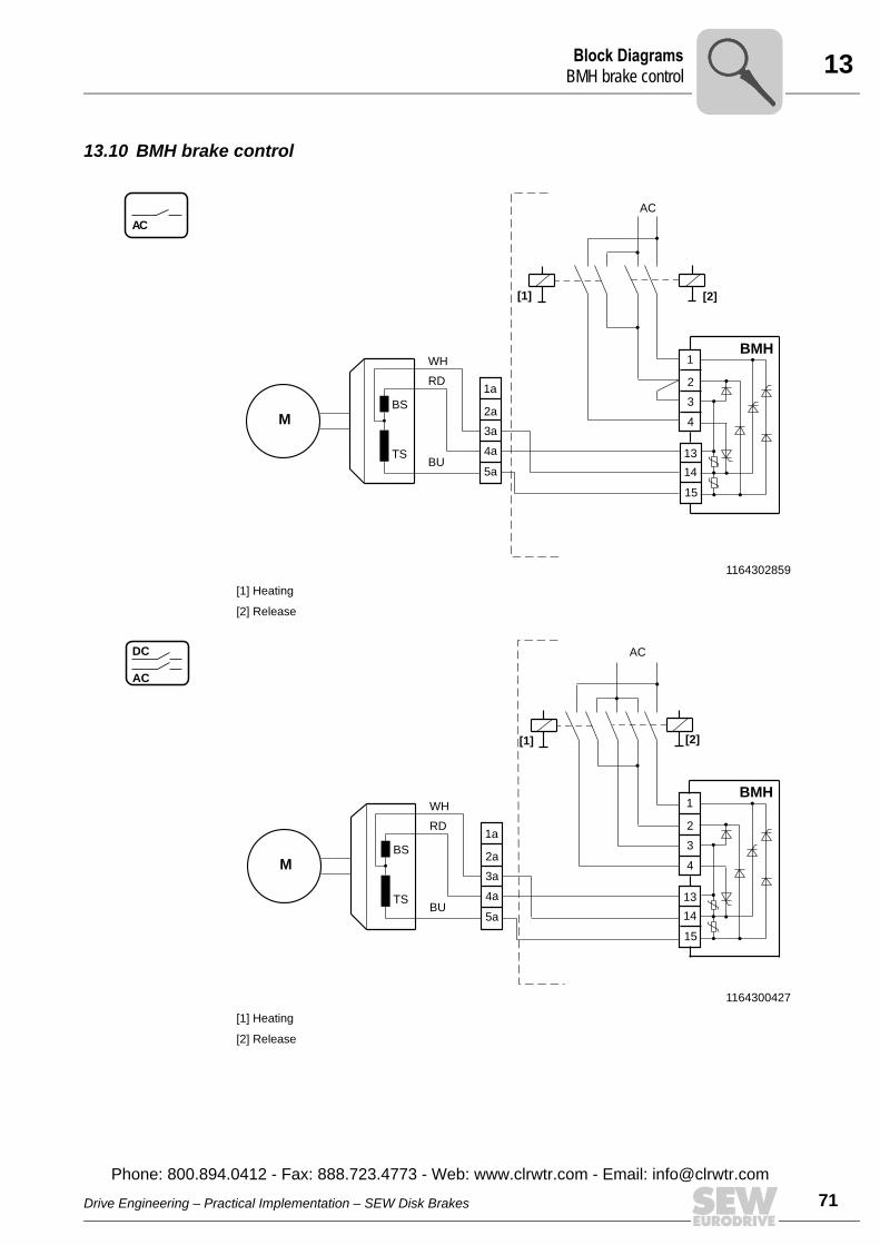
13Block DiagramsBMH brake contro
13.10 BMH brake control
1164302859
[1] Heating
[2] Release
1164300427
[1] Heating
[2] Release
AC
BU
AC
WH
RD1a
2a
5a
4a
3aM
TS
BS
[1] [2]
1
2
13
14
15
4
3
BMH
AC
DC
BU
AC
WH
RD1a
2a
5a
4a
3aM
TS
BS
[2][1]
1
2
13
14
15
4
3
BMH
Drive Engineering – Practical Implementation – SEW Disk Brakes
Phone: 800.894.0412 - Fax: 888.723.4773 - Web: www.clrwtr.com - Email: info@
l
71clrwtr.com
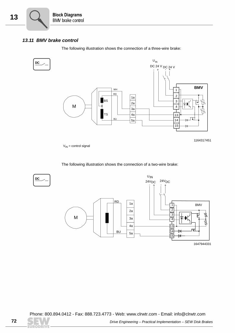
13 lock DiagramsMV brake control
72
13.11 BMV brake controlThe following illustration shows the connection of a three-wire brake:
The following illustration shows the connection of a two-wire brake:
1164317451
VIN = control signal
DC
1a
2a
3a
4a
5a
M
BS
TS
RD
WH
BU
- + - +
1
2
13
14
15
4
3
BMV
DC 24 V
UIN
DC 24 V
1647944331
DC
+-
U
24V
+-
IN
DC
1a
2a
3a
4a
5a
1
2
3
13
14
15
4
BMV
24VDC
RD
BU
M
BB
Drive Engineering – Practical Implementation – SEW Disk Brakes
Phone: 800.894.0412 - Fax: 888.723.4773 - Web: www.clrwtr.com - Email: [email protected]
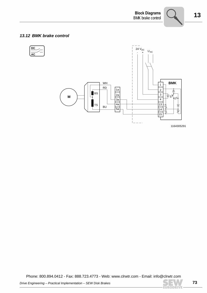
13Block DiagramsBMK brake contro
13.12 BMK brake control
1164305291
AC
DC
BU
U+- AC
WH
RD1a
2a
5a
4a
3a
BMK1
24 VDC
2
13
14
15
4
3M
TS
BS
Drive Engineering – Practical Implementation – SEW Disk Brakes
Phone: 800.894.0412 - Fax: 888.723.4773 - Web: www.clrwtr.com - Email: info@
l
73clrwtr.com
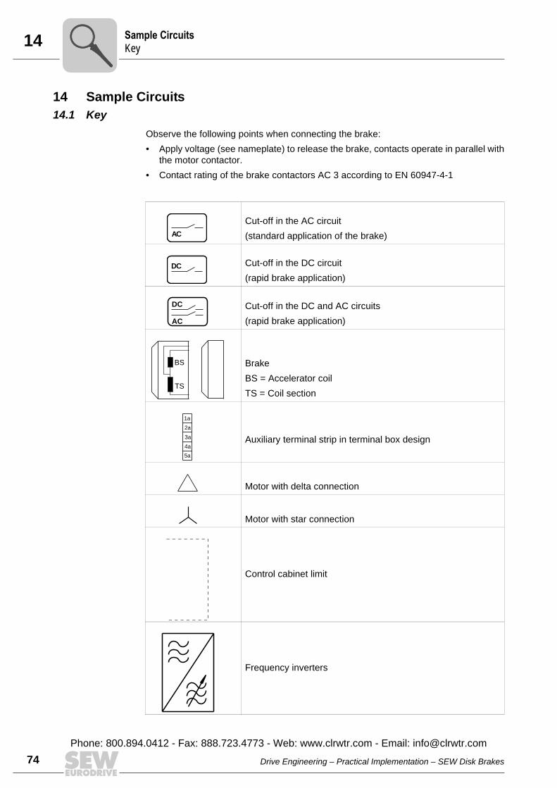
14 ample Circuitsey
74
14 Sample Circuits14.1 Key
Observe the following points when connecting the brake:• Apply voltage (see nameplate) to release the brake, contacts operate in parallel with
the motor contactor.• Contact rating of the brake contactors AC 3 according to EN 60947-4-1
Cut-off in the AC circuit (standard application of the brake)
Cut-off in the DC circuit(rapid brake application)
Cut-off in the DC and AC circuits(rapid brake application)
BrakeBS = Accelerator coilTS = Coil section
Auxiliary terminal strip in terminal box design
Motor with delta connection
Motor with star connection
Control cabinet limit
Frequency inverters
AC
DC
AC
DC
BS
TS
1a
2a
5a
4a
3a
SK
Drive Engineering – Practical Implementation – SEW Disk Brakes
Phone: 800.894.0412 - Fax: 888.723.4773 - Web: www.clrwtr.com - Email: [email protected]
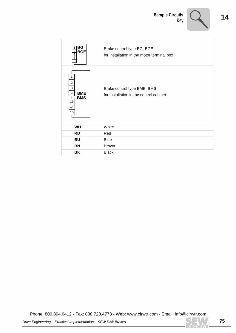
14Sample CircuitsKey
Brake control type BG, BGE for installation in the motor terminal box
Brake control type BME, BMS for installation in the control cabinet
WH WhiteRD RedBU BlueBN BrownBK Black
BGE
BG12345
BME
1
2
13
14
15
4
3
BMS
Drive Engineering – Practical Implementation – SEW Disk Brakes
Phone: 800.894.0412 - Fax: 888.723.4773 - Web: www.clrwtr.com - Email: info@
75clrwtr.com
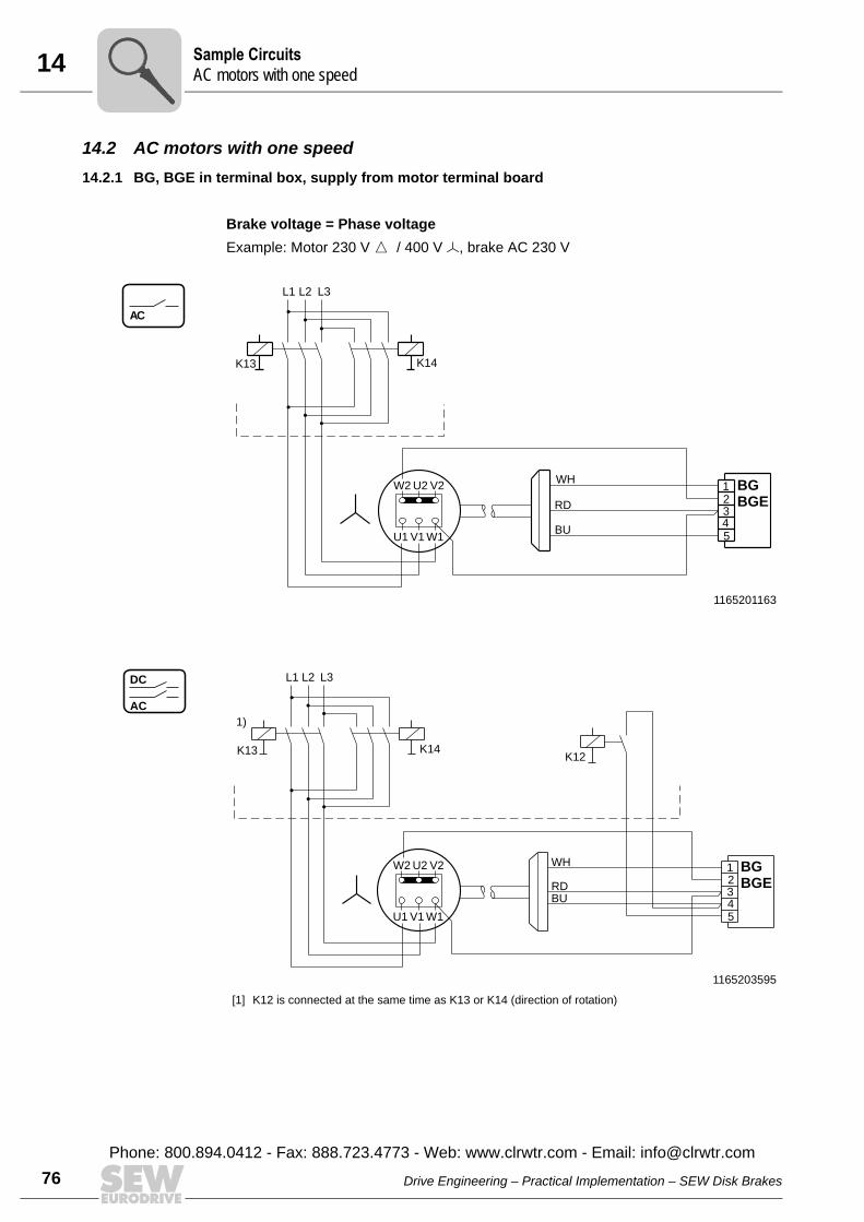
14 ample CircuitsC motors with one speed
76
14.2 AC motors with one speed14.2.1 BG, BGE in terminal box, supply from motor terminal board
Brake voltage = Phase voltageExample: Motor 230 V Ö / 400 V Õ, brake AC 230 V
1165201163
1165203595
[1] K12 is connected at the same time as K13 or K14 (direction of rotation)
AC
U2 V2
V1
W2
W1U1
K13
BGE
BG123
RD
L1 L3
4
L2
5
K14
WH
BU
AC
DC
5
L1
BU
L3
WH
L2
BGE
BG123
RD
K12K14
1)
K13
4
U2 V2
V1
W2
W1U1
SA
Drive Engineering – Practical Implementation – SEW Disk Brakes
Phone: 800.894.0412 - Fax: 888.723.4773 - Web: www.clrwtr.com - Email: [email protected]
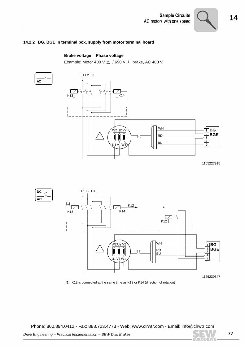
14Sample CircuitsAC motors with one speed
14.2.2 BG, BGE in terminal box, supply from motor terminal board
Brake voltage = Phase voltageExample: Motor 400 V Ö / 690 V Õ, brake, AC 400 V
1165227915
1165230347
[1] K12 is connected at the same time as K13 or K14 (direction of rotation)
AC
U2 V2
V1
W2
W1U1
K13
BGE
BG123
RD
L1 L3
4
L2
5
K14
WH
BU
AC
DC
5
L1
BU
L3
WH
L2
BGE
BG123
RD
K12
K14
[1]
K13
4
U2 V2
V1
W2
W1U1
K12
Drive Engineering – Practical Implementation – SEW Disk Brakes
Phone: 800.894.0412 - Fax: 888.723.4773 - Web: www.clrwtr.com - Email: info@
77clrwtr.com
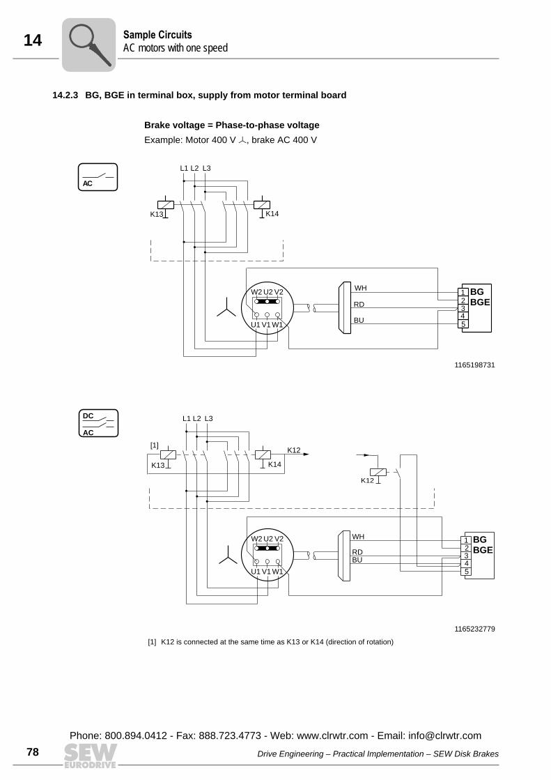
14 ample CircuitsC motors with one speed
78
14.2.3 BG, BGE in terminal box, supply from motor terminal board
Brake voltage = Phase-to-phase voltageExample: Motor 400 V Õ, brake AC 400 V
1165198731
1165232779
[1] K12 is connected at the same time as K13 or K14 (direction of rotation)
AC
U2 V2
V1
W2
W1U1
K13
BGE
BG123
RD
L1 L3
4
L2
5
K14
WH
BU
AC
DC
5
L1
BU
L3
WH
L2
BGE
BG123
RD
K12
K14
[1]
K13
4
U2 V2
V1
W2
W1U1
K12
SA
Drive Engineering – Practical Implementation – SEW Disk Brakes
Phone: 800.894.0412 - Fax: 888.723.4773 - Web: www.clrwtr.com - Email: [email protected]

14Sample CircuitsAC motors with one speed
14.2.4 BG, BGE in terminal box, external supply
1165235211
1165237643
AC
5
L1
BU
L3 AC
WH
L2
BGE
BG123RD
K12
K14
K12[1]
K13
43
M
AC
DC
5
BU
AC
WH
BGE
BG123RD
K12
4
Drive Engineering – Practical Implementation – SEW Disk Brakes
Phone: 800.894.0412 - Fax: 888.723.4773 - Web: www.clrwtr.com - Email: info@
79clrwtr.com
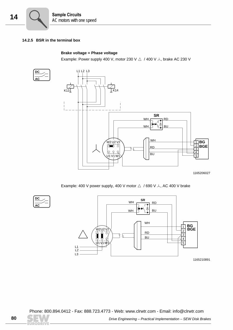
14 ample CircuitsC motors with one speed
80
14.2.5 BSR in the terminal box
Brake voltage = Phase voltageExample: Power supply 400 V, motor 230 V Ö / 400 V Õ, brake AC 230 V
Example: 400 V power supply, 400 V motor Ö / 690 V Õ, AC 400 V brake
1165206027
AC
DC
U2 V2
V1
W2
W1U1
K13
BGE
BG
SR
123
RD
L1 L3
4
L2
5
K14
WH
WH
WH
BU
RD
BU
1165210891
AC
DC
WH
WH
BU
RD
V2U2
SR
L1
V1U1 W1
W2
L3
L2
RD
WH
BU
1
2
5
4
3
BGEBG
SA
Drive Engineering – Practical Implementation – SEW Disk Brakes
Phone: 800.894.0412 - Fax: 888.723.4773 - Web: www.clrwtr.com - Email: [email protected]
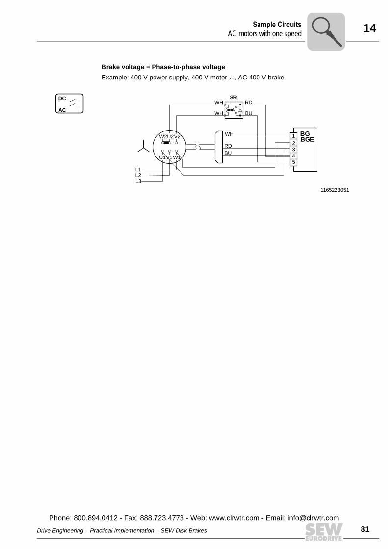
14Sample CircuitsAC motors with one speed
Brake voltage = Phase-to-phase voltageExample: 400 V power supply, 400 V motor Õ, AC 400 V brake
1165223051
AC
DC
U2V2
V1
W2
W1U1
SR
RD
WH
WH
WH
BU
RD
BU
L1
L3L2
1
2
5
4
3
BGEBG
Drive Engineering – Practical Implementation – SEW Disk Brakes
Phone: 800.894.0412 - Fax: 888.723.4773 - Web: www.clrwtr.com - Email: info@
81clrwtr.com
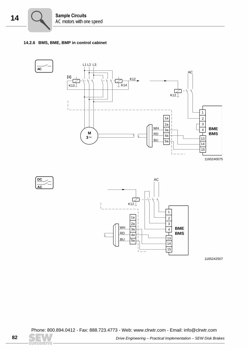
14 ample CircuitsC motors with one speed
82
14.2.6 BMS, BME, BMP in control cabinet
1165240075
ACL1
BU
L3
AC
WH
L2
RD
K12
K14
K12[1]
K13
3
M
1a
2a
5a
4a
3a
1
2
13
14
15
4
3
BME
BMS
1165242507
AC
DC AC
BU
WH
RD
K12
1a
2a
5a
4a
3a
1
2
13
14
15
4
3
BME
BMS
SA
Drive Engineering – Practical Implementation – SEW Disk Brakes
Phone: 800.894.0412 - Fax: 888.723.4773 - Web: www.clrwtr.com - Email: [email protected]
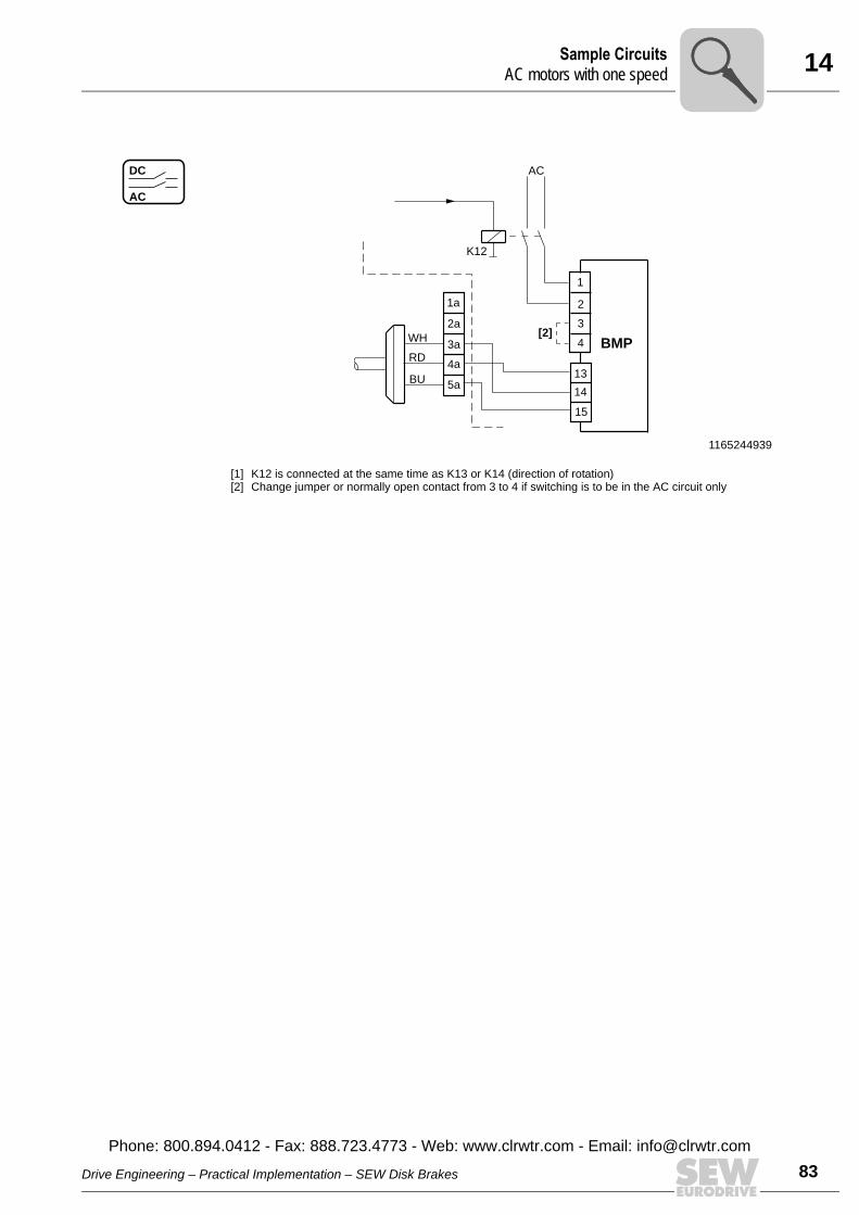
14Sample CircuitsAC motors with one speed
1165244939
AC
DC AC
[2]
BU
WH
RD
K12
1a
2a
5a
4a
3a BMP
1
2
13
14
15
4
3
[1] K12 is connected at the same time as K13 or K14 (direction of rotation)[2] Change jumper or normally open contact from 3 to 4 if switching is to be in the AC circuit only
Drive Engineering – Practical Implementation – SEW Disk Brakes
Phone: 800.894.0412 - Fax: 888.723.4773 - Web: www.clrwtr.com - Email: info@
83clrwtr.com
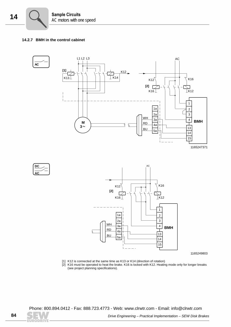
14 ample CircuitsC motors with one speed
84
14.2.7 BMH in the control cabinet
1165247371
AC
L1
BU
L3 AC
WH
L2
RD
K16 K12
K12K14
K12[1]
K13
3
M
1a
2a
5a
4a
3a
[2]
BMH
1
2
13
14
15
4
3
K16
1165249803
AC
DC
[2]
BU
AC
WH
RD
K16 K12
K12
1a
2a
5a
4a
3aBMH
1
2
13
14
15
4
3
K16
[1] K12 is connected at the same time as K13 or K14 (direction of rotation)[2] K16 must be operated to heat the brake. K16 is locked with K12. Heating mode only for longer breaks
(see project planning specifications).
SA
Drive Engineering – Practical Implementation – SEW Disk Brakes
Phone: 800.894.0412 - Fax: 888.723.4773 - Web: www.clrwtr.com - Email: [email protected]
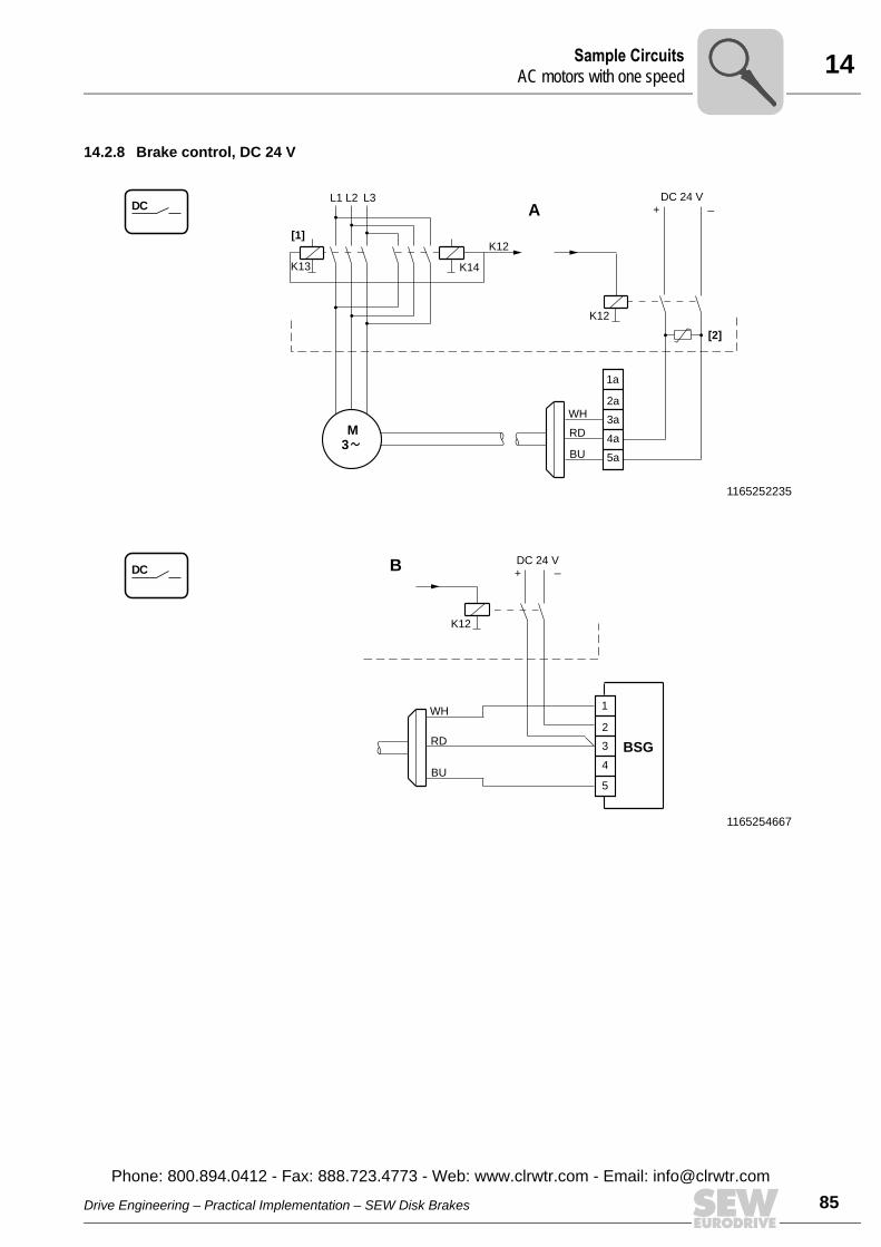
14Sample CircuitsAC motors with one speed
14.2.8 Brake control, DC 24 V
1165252235
DCL1
BU
L3+ _
DC 24 V
WH
L2
RD
K12
K14
K12
[2]
K13
3
M
1a
2a
5a
4a
3a
A
[1]
1165254667
DC
BU
+ _DC 24 V
WH
RD
K12
1
2
5
4
3 BSG
B
Drive Engineering – Practical Implementation – SEW Disk Brakes
Phone: 800.894.0412 - Fax: 888.723.4773 - Web: www.clrwtr.com - Email: info@
85clrwtr.com
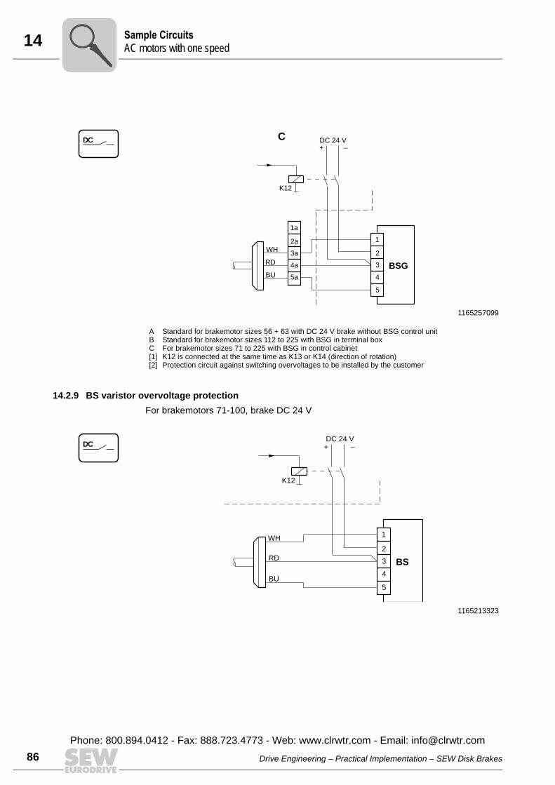
14 ample CircuitsC motors with one speed
86
14.2.9 BS varistor overvoltage protectionFor brakemotors 71-100, brake DC 24 V
1165257099
DC
BU
WH
RD
1a
2a
5a
4a
3a
+ _
K12
1
2
5
4
3 BSG
C DC 24 V
A Standard for brakemotor sizes 56 + 63 with DC 24 V brake without BSG control unitB Standard for brakemotor sizes 112 to 225 with BSG in terminal boxC For brakemotor sizes 71 to 225 with BSG in control cabinet[1] K12 is connected at the same time as K13 or K14 (direction of rotation)[2] Protection circuit against switching overvoltages to be installed by the customer
1165213323
DC
BU
+ _DC 24 V
WH
RD
K12
1
2
5
4
3 BS
SA
Drive Engineering – Practical Implementation – SEW Disk Brakes
Phone: 800.894.0412 - Fax: 888.723.4773 - Web: www.clrwtr.com - Email: [email protected]
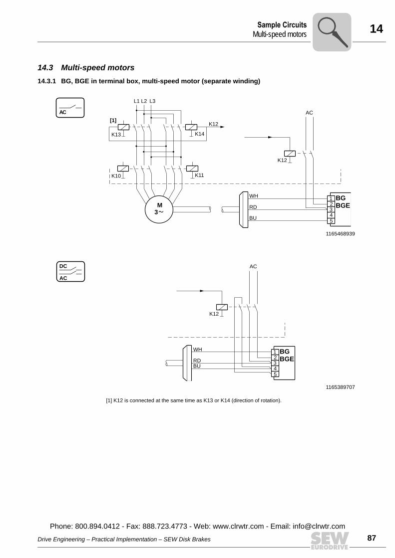
14Sample CircuitsMulti-speed motors
14.3 Multi-speed motors14.3.1 BG, BGE in terminal box, multi-speed motor (separate winding)
1165468939
AC
5
L1
BU
L3
AC
WH
L2
BGE
BG123RD
K12
K14
K12[1]
K13
K11K10
43
M
1165389707
AC
DC
5
BU
AC
WH
BGE
BG123RD
K12
4
[1] K12 is connected at the same time as K13 or K14 (direction of rotation).
Drive Engineering – Practical Implementation – SEW Disk Brakes
Phone: 800.894.0412 - Fax: 888.723.4773 - Web: www.clrwtr.com - Email: info@
87clrwtr.com
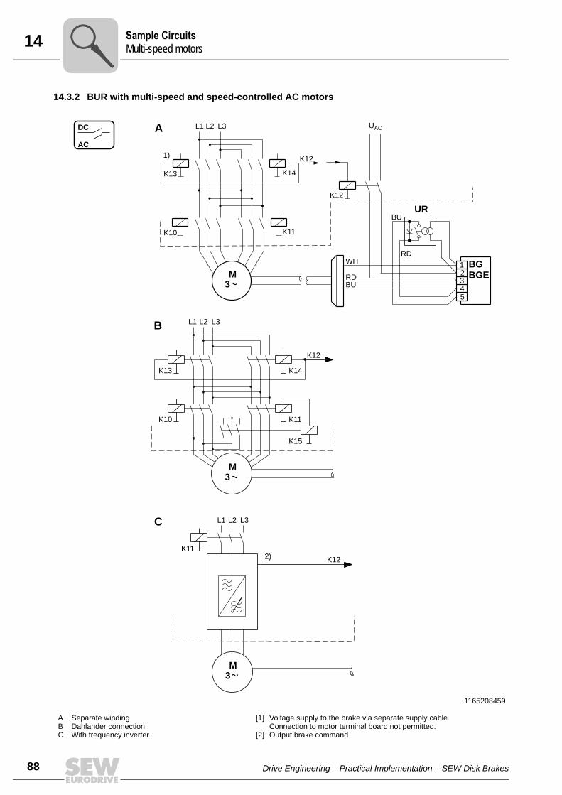
14 ample Circuitsulti-speed motors
88
14.3.2 BUR with multi-speed and speed-controlled AC motors
1165208459
A Separate windingB Dahlander connectionC With frequency inverter
[1] Voltage supply to the brake via separate supply cable. Connection to motor terminal board not permitted.
[2] Output brake command
AC
DC
5
L1
BU
BU
L3 UAC
WH
L2
BGE
BG123RD
RD
K12
K14
K121)
K13
K11K10
43
M
K10
M
L1
K13
K11
K14
3
K15
L1 L3L2
M
K11
3
L3L2
K12
K12
2)
B
A
C
UR
SM
Drive Engineering – Practical Implementation – SEW Disk Brakes
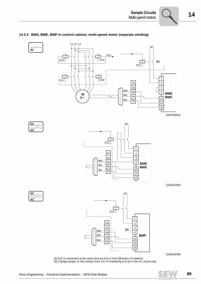
14Sample CircuitsMulti-speed motors
14.3.3 BMS, BME, BMP in control cabinet, multi-speed motor (separate winding)
1165259531
1165261963
1165264395[1] K12 is connected at the same time as K13 or K14 (direction of rotation).[2] Change jumper or NO contact from 3 to 4 if switching is to be in the AC circuit only.
AC
BU
AC
WH
RD
K12
1a
2a
5a
4a
3a
L1 L3L2
K14
K12
[1]K13
K10K11
3
M BME
1
2
13
14
15
4
3
BMS
AC
DC AC
BU
WH
RD
K12
1a
2a
5a
4a
3aBME
1
2
13
14
15
4
3
BMS
AC
DC AC
[2]
BU
WH
RD
K12
1a
2a
5a
4a
3a
1
2
13
14
15
4
3
BMP
Drive Engineering – Practical Implementation – SEW Disk Brakes
89
14 ample Circuitsulti-speed motors
90
14.3.4 BMH in control cabinet, multi-speed motor (separate winding)
1165266827
AC
L1 L3L2
K14
K12[1]
K13
K11K10
3
M
BU
AC
WH
RD
K16 K12
K12 K16
1a
2a
5a
4a
3aBMH
1
2
13
14
15
4
3
1165269259
AC
DC
[2]
BU
AC
WH
RD
K16 K12
K16K12
1a
2a
5a
4a
3aBMH
1
2
13
14
15
4
3
[1] K12 is connected at the same time as K13 or K14 (direction of rotation).[2] K16 must be operated to heat the brake. K16 is locked with K12. Heating mode only for longer breaks
(see project planning specifications).
SM
Drive Engineering – Practical Implementation – SEW Disk Brakes
Phone: 800.894.0412 - Fax: 888.723.4773 - Web: www.clrwtr.com - Email: [email protected]
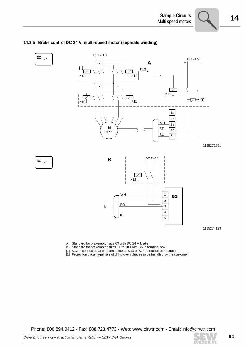
14Sample CircuitsMulti-speed motors
14.3.5 Brake control DC 24 V, multi-speed motor (separate winding)
1165271691
1165274123
DCL1 L3L2
K14
K12[1]
K13
K11K10
3
M
BU
+ _DC 24 V
WH
RD
K12
[2]
1a
2a
5a
4a
3a
A
DCDC 24 V+ -
K12
B
1
2
5
4
3
BS
BU
WH
RD
A Standard for brakemotor size 63 with DC 24 V brake B Standard for brakemotor sizes 71 to 100 with BS in terminal box[1] K12 is connected at the same time as K13 or K14 (direction of rotation)[2] Protection circuit against switching overvoltages to be installed by the customer
Drive Engineering – Practical Implementation – SEW Disk Brakes
Phone: 800.894.0412 - Fax: 888.723.4773 - Web: www.clrwtr.com - Email: info@
91clrwtr.com
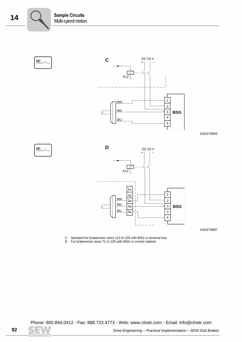
14 ample Circuitsulti-speed motors
92
1165276555
1165278987
DC
BU
+ _DC 24 V
WH
RD
K12
1
2
5
4
3 BSG
C
DC
BU
WH
RD
1a
2a
5a
4a
3a
+ _DC 24 V
K12
1
2
5
4
3 BSG
D
C Standard for brakemotor sizes 112 to 225 with BSG in terminal boxD For brakemotor sizes 71 to 225 with BSG in control cabinet
SM
Drive Engineering – Practical Implementation – SEW Disk Brakes
Phone: 800.894.0412 - Fax: 888.723.4773 - Web: www.clrwtr.com - Email: [email protected]
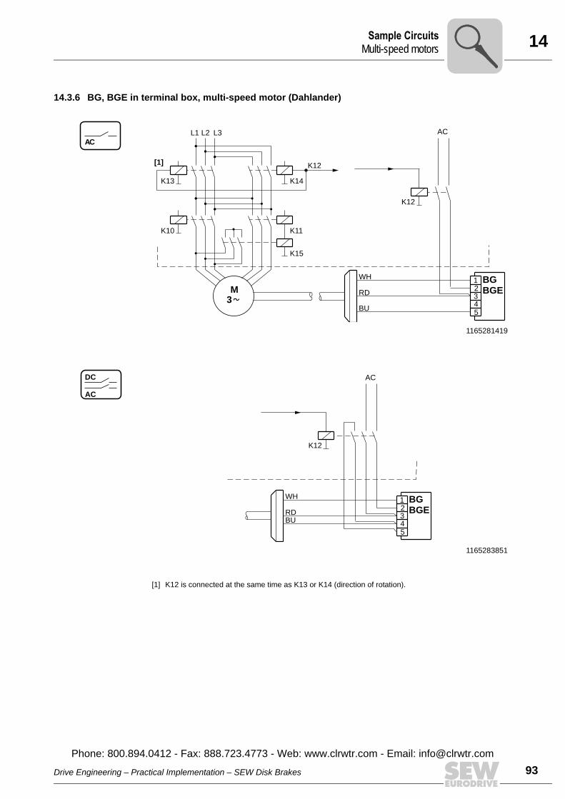
14Sample CircuitsMulti-speed motors
14.3.6 BG, BGE in terminal box, multi-speed motor (Dahlander)
1165281419
AC
5BU
AC
WH
BGE
BG123RD
K12
4
K12
K15
3
K14
K11
K13
L1
M
K10
[1]
L2 L3
1165283851
AC
DC
5
BU
AC
WH
BGE
BG123RD
K12
4
[1] K12 is connected at the same time as K13 or K14 (direction of rotation).
Drive Engineering – Practical Implementation – SEW Disk Brakes
Phone: 800.894.0412 - Fax: 888.723.4773 - Web: www.clrwtr.com - Email: info@
93clrwtr.com

14 ample Circuitsulti-speed motors
94
14.3.7 BMS, BME, BMP in control cabinet, multi-speed motor (Dahlander)
1165286283
1165288715
AC
K12
K15
3
K14
K11
K13
L1
M
K10
[1]
L2 L3
BU
AC
WH
RD
K12
1a
2a
5a
4a
3a BME
BMS
1
2
13
14
15
4
3
AC
DC AC
BU
WH
RD
K12
1a
2a
5a
4a
3a BME
BMS
1
2
13
14
15
4
3
SM
Drive Engineering – Practical Implementation – SEW Disk Brakes
Phone: 800.894.0412 - Fax: 888.723.4773 - Web: www.clrwtr.com - Email: [email protected]
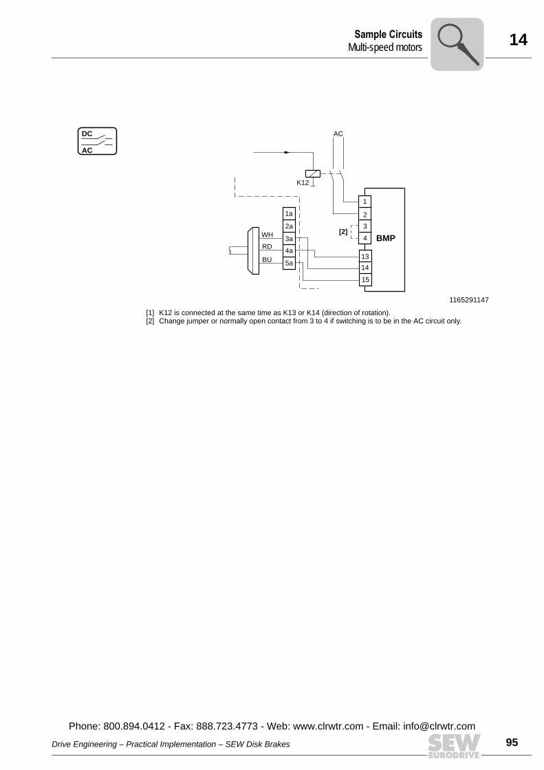
14Sample CircuitsMulti-speed motors
1165291147
[1] K12 is connected at the same time as K13 or K14 (direction of rotation).[2] Change jumper or normally open contact from 3 to 4 if switching is to be in the AC circuit only.
AC
DC AC
[2]
BU
WH
RD
K12
1a
2a
5a
4a
3a BMP
1
2
13
14
15
4
3
Drive Engineering – Practical Implementation – SEW Disk Brakes
Phone: 800.894.0412 - Fax: 888.723.4773 - Web: www.clrwtr.com - Email: info@
95clrwtr.com

14 ample Circuitsulti-speed motors
96
14.3.8 BMH in control cabinet, multi-speed motor (Dahlander)
1165293579
AC
DC
K12
K15
3
K14
K11
K13
L1
M
K10
[1]
L2 L3
BU
AC
WH
RD
K16 K12
K12 K16
1a
2a
5a
4a
3a BMH
1
2
13
14
15
4
3
1165296011
AC
DC
[2]
BU
AC
WH
RD
K16 K12
K16K12
1a
2a
5a
4a
3aBMH
1
2
13
14
15
4
3
[1] K12 is connected at the same time as K13 or K14 (direction of rotation).[2] K16 must be operated to heat the brake. K16 is locked with K12. Heating mode only for longer breaks
(see project planning specifications).
SM
Drive Engineering – Practical Implementation – SEW Disk Brakes
Phone: 800.894.0412 - Fax: 888.723.4773 - Web: www.clrwtr.com - Email: [email protected]

14Sample CircuitsMulti-speed motors
14.3.9 Brake control, DC 24 V, multi-speed motor (Dahlander)
1165298443
DC
K12
K15
3
K14
K11
K13
L1
M
K10
[1]
L2 L3
BU
+ _DC 24 V
WH
RD
K12
[2]
1a
2a
5a
4a
3a
A
1165300875
A Standard for brakemotor size 63 with DC 24 V brake B Standard for brakemotor sizes 71 to 100 with BS in terminal box[1] K12 is connected at the same time as K13 or K14 (direction of rotation)[2] Protection circuit against switching overvoltages to be installed by the customer
DC DC 24 V
K12
+ –B
1
2
5
4
3 BSBU
WH
RD
Drive Engineering – Practical Implementation – SEW Disk Brakes
Phone: 800.894.0412 - Fax: 888.723.4773 - Web: www.clrwtr.com - Email: info@
97clrwtr.com
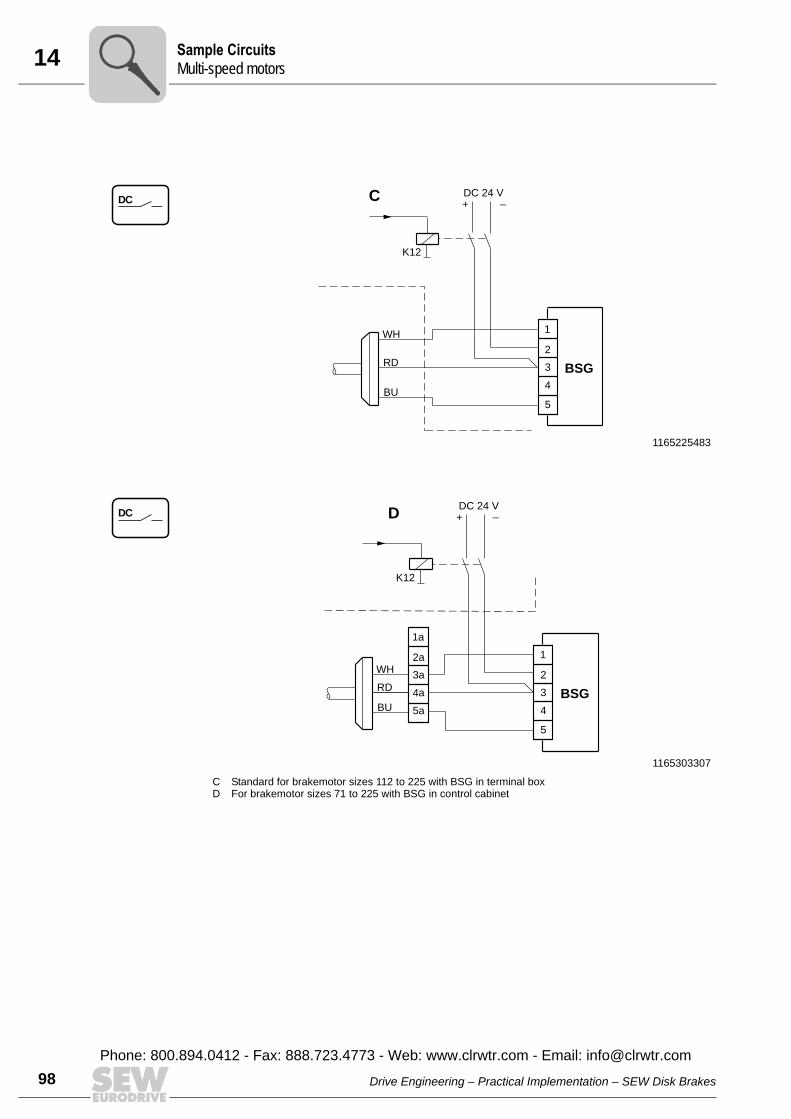
14 ample Circuitsulti-speed motors
98
1165225483
DC
BU
+ _DC 24 V
WH
RD
K12
1
2
5
4
3 BSG
C
1165303307
C Standard for brakemotor sizes 112 to 225 with BSG in terminal boxD For brakemotor sizes 71 to 225 with BSG in control cabinet
DC
BU
WH
RD
1a
2a
5a
4a
3a
+ _DC 24 V
K12
1
2
5
4
3 BSG
D
SM
Drive Engineering – Practical Implementation – SEW Disk Brakes
Phone: 800.894.0412 - Fax: 888.723.4773 - Web: www.clrwtr.com - Email: [email protected]
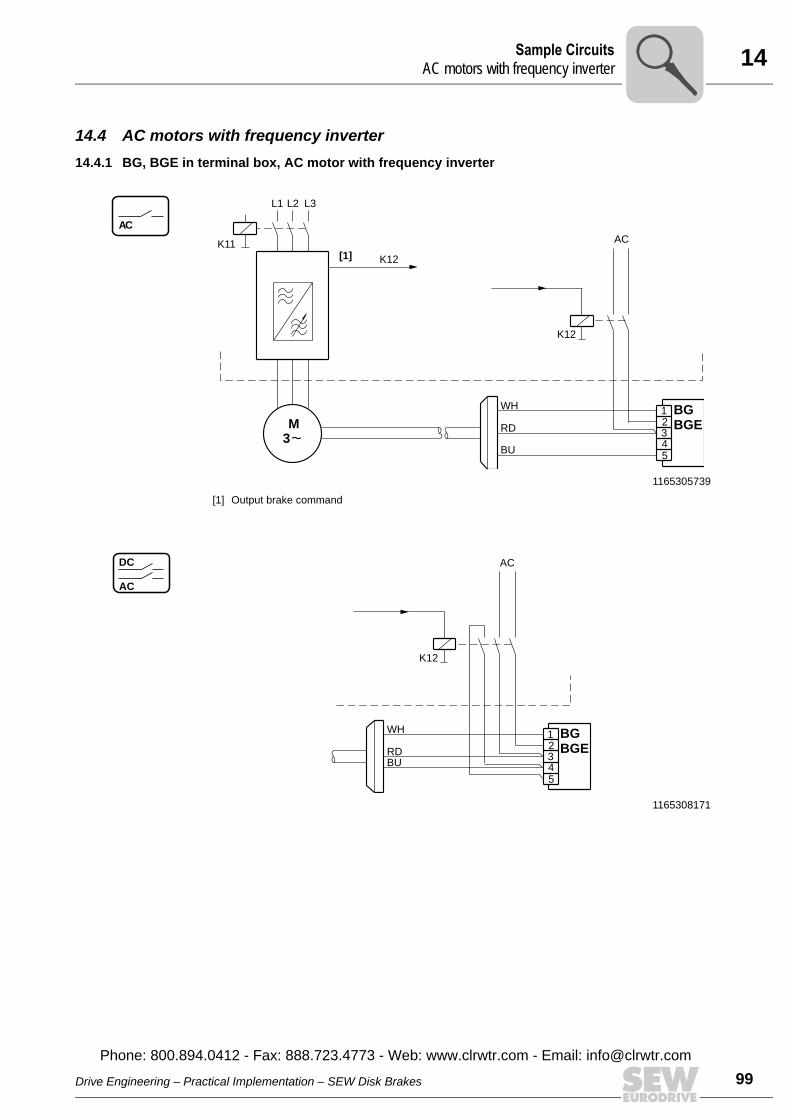
14Sample CircuitsAC motors with frequency inverter
14.4 AC motors with frequency inverter14.4.1 BG, BGE in terminal box, AC motor with frequency inverter
1165305739
[1] Output brake command
1165308171
AC
5BU
AC
WH
BGE
BG123RD
K12
4
K12
3
K11
M
L2 L3
[1]
L1
AC
DC
5
BU
AC
WH
BGE
BG123RD
K12
4
Drive Engineering – Practical Implementation – SEW Disk Brakes
Phone: 800.894.0412 - Fax: 888.723.4773 - Web: www.clrwtr.com - Email: info@
99clrwtr.com

14 ample CircuitsC motors with frequency inverter
100
14.4.2 BMS, BME, BMP in control cabinet, AC motor with frequency inverter
1165310603
1165313035
AC
K12
3
K11
M
L2 L3
[1]
L1
BU
AC
WH
RD
K12
1a
2a
5a
4a
3a BME
BMS
1
2
13
14
15
4
3
AC
DC AC
BU
WH
RD
K12
1a
2a
5a
4a
3a BME
BMS
1
2
13
14
15
4
3
SA
Drive Engineering – Practical Implementation – SEW Disk Brakes
Phone: 800.894.0412 - Fax: 888.723.4773 - Web: www.clrwtr.com - Email: [email protected]
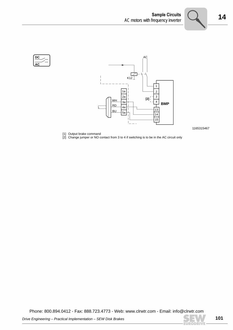
14Sample CircuitsAC motors with frequency inverter
1165315467
[1] Output brake command[2] Change jumper or NO contact from 3 to 4 if switching is to be in the AC circuit only
AC
DC AC
[2]
BU
WH
RD
K12
1a
2a
5a
4a
3aBMP
1
2
13
14
15
4
3
Drive Engineering – Practical Implementation – SEW Disk Brakes
Phone: 800.894.0412 - Fax: 888.723.4773 - Web: www.clrwtr.com - Email: info@
101clrwtr.com
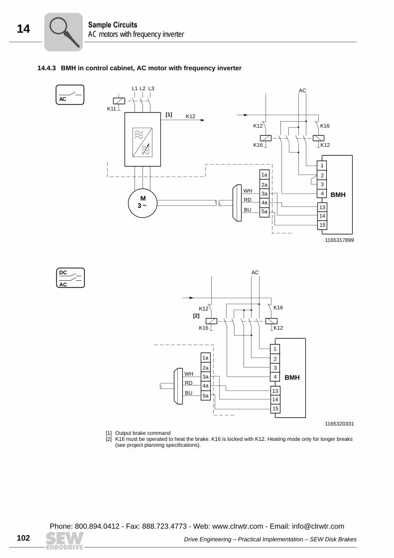
14 ample CircuitsC motors with frequency inverter
102
14.4.3 BMH in control cabinet, AC motor with frequency inverter
1165317899
AC
BU
AC
WH
RD
K16 K12
K12 K16
1a
2a
5a
4a
3a
K12
3
K11
M
L2 L3
[1]
L1
BMH
1
2
13
14
15
4
3
1165320331
[1] Output brake command[2] K16 must be operated to heat the brake. K16 is locked with K12. Heating mode only for longer breaks
(see project planning specifications).
AC
DC
[2]
BU
AC
WH
RD
K16 K12
K16K12
1a
2a
5a
4a
3a BMH
1
2
13
14
15
4
3
SA
Drive Engineering – Practical Implementation – SEW Disk Brakes
Phone: 800.894.0412 - Fax: 888.723.4773 - Web: www.clrwtr.com - Email: [email protected]
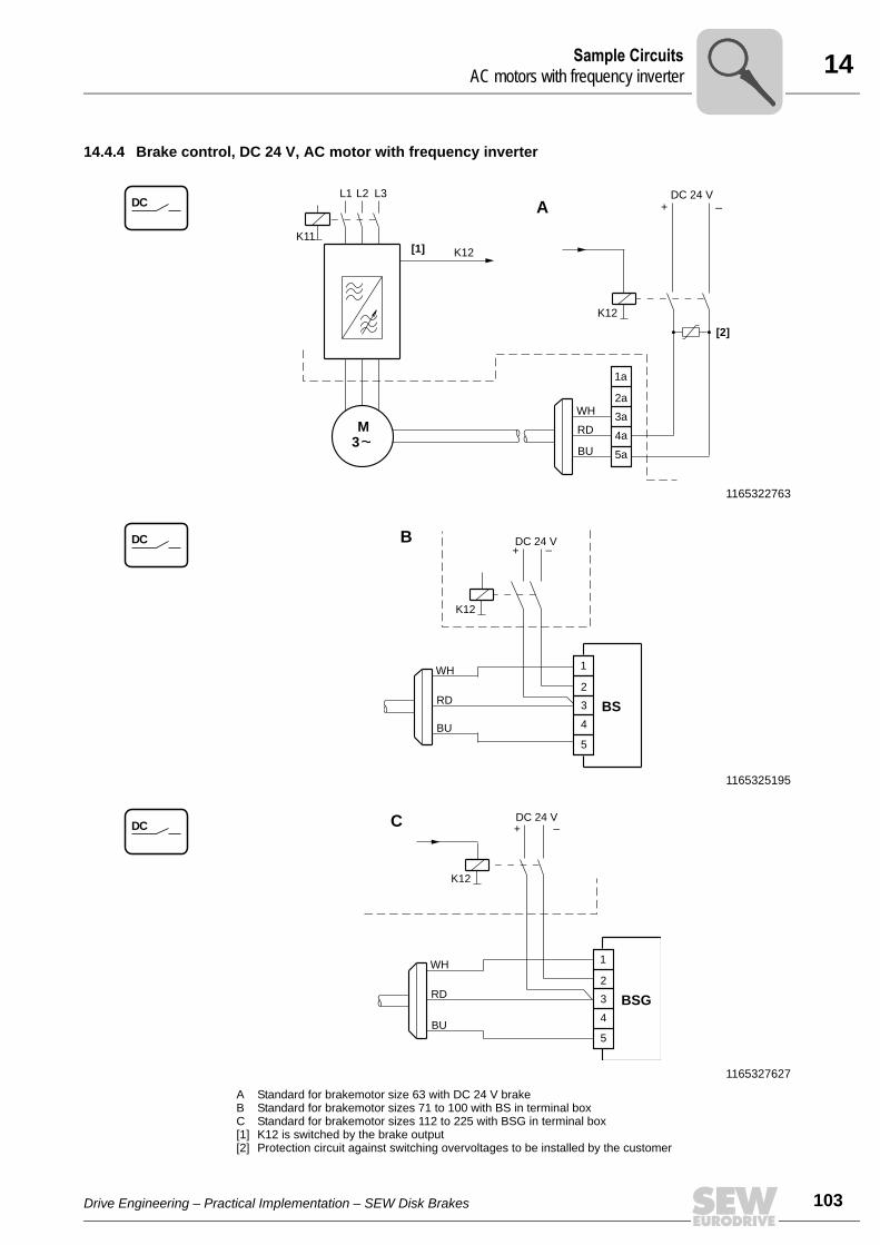
14Sample CircuitsAC motors with frequency inverter
14.4.4 Brake control, DC 24 V, AC motor with frequency inverter
1165322763
1165325195
1165327627
A Standard for brakemotor size 63 with DC 24 V brake B Standard for brakemotor sizes 71 to 100 with BS in terminal boxC Standard for brakemotor sizes 112 to 225 with BSG in terminal box[1] K12 is switched by the brake output[2] Protection circuit against switching overvoltages to be installed by the customer
DC
BU
+ _DC 24 V
WH
RD
K12
[2]
1a
2a
5a
4a
3a
A
K12
3
K11
M
L2 L3
[1]
L1
DC DC 24 V
K12
+ –B
BU
WH
RD
1
2
5
4
3 BS
DC
BU
+ _DC 24 V
WH
RD
K12
1
2
5
4
3 BSG
C
Drive Engineering – Practical Implementation – SEW Disk Brakes
103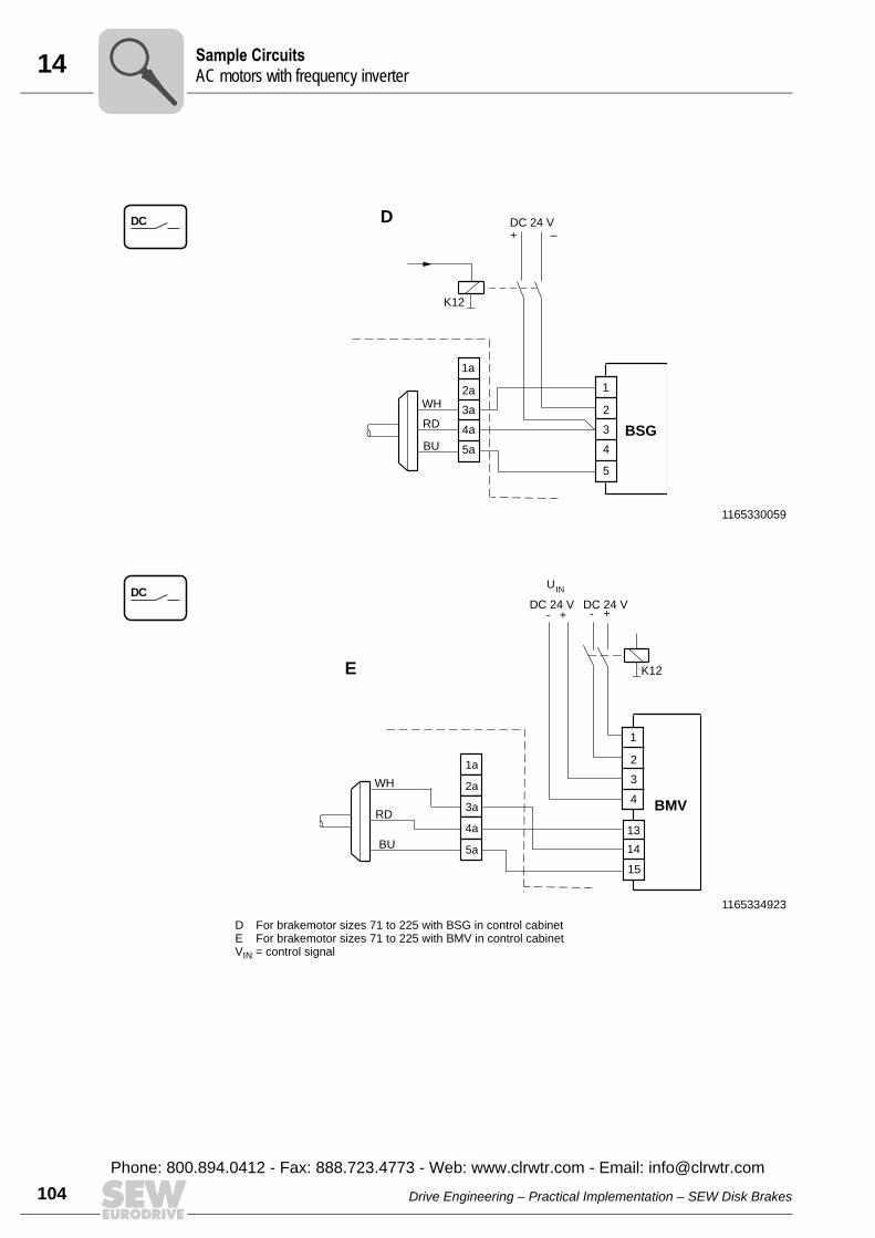
14 ample CircuitsC motors with frequency inverter
104
1165330059
DC
BU
WH
RD
1a
2a
5a
4a
3a
+ _DC 24 V
K12
1
2
5
4
3 BSG
D
1165334923
D For brakemotor sizes 71 to 225 with BSG in control cabinetE For brakemotor sizes 71 to 225 with BMV in control cabinetVIN = control signal
DC
1a
2a
3a
4a
5aBU
UIN
DC 24 V- + - +
BMV
WH
RD
E K12
1
2
13
14
15
4
3
DC 24 V
SA
Drive Engineering – Practical Implementation – SEW Disk Brakes
Phone: 800.894.0412 - Fax: 888.723.4773 - Web: www.clrwtr.com - Email: [email protected]
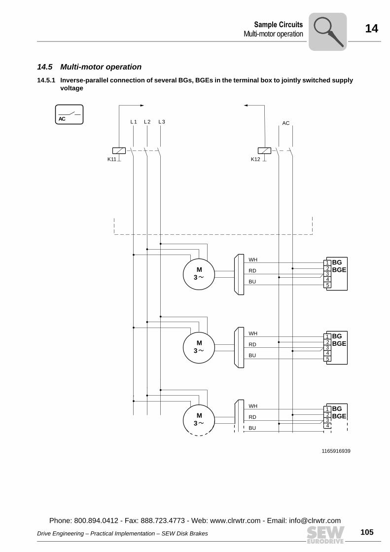
14Sample CircuitsMulti-motor operation
14.5 Multi-motor operation14.5.1 Inverse-parallel connection of several BGs, BGEs in the terminal box to jointly switched supply
voltage
1165916939
AC
3
M
WH
RD
BU
L1
K11
M
L3L2 AC
K12
3
5
BGE
BG1234
M
WH
RD
BU3
BGE
BG1234
WH
RD
BU5
BGE
BG1234
Drive Engineering – Practical Implementation – SEW Disk Brakes
Phone: 800.894.0412 - Fax: 888.723.4773 - Web: www.clrwtr.com - Email: info@
105clrwtr.com
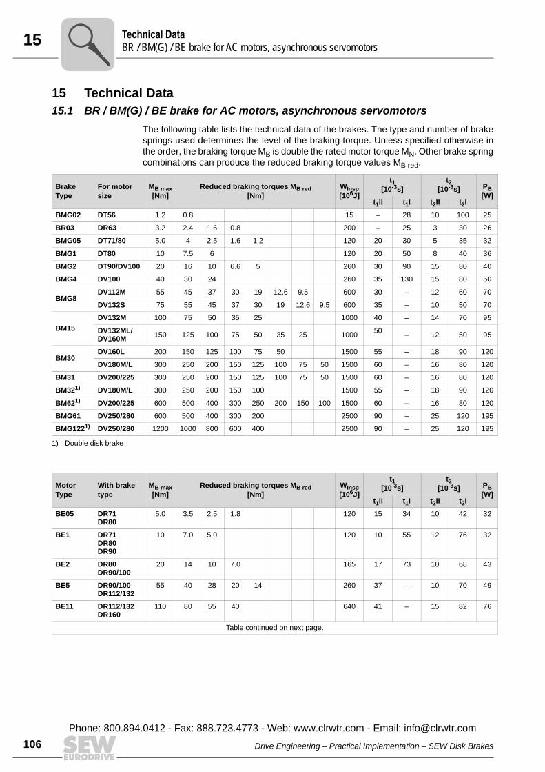
15 echnical DataR / BM(G) / BE brake for AC motors, asynchronous servomotors
106
15 Technical Data15.1 BR / BM(G) / BE brake for AC motors, asynchronous servomotors
The following table lists the technical data of the brakes. The type and number of brakesprings used determines the level of the braking torque. Unless specified otherwise inthe order, the braking torque MB is double the rated motor torque MN. Other brake springcombinations can produce the reduced braking torque values MB red.
BrakeType
For motorsize
MB max[Nm]
Reduced braking torques MB red[Nm]
WInsp[106J]
t1[10-3s]
t2[10-3s] PB
[W]t1II t1I t2II t2I
BMG02 DT56 1.2 0.8 15 – 28 10 100 25
BR03 DR63 3.2 2.4 1.6 0.8 200 – 25 3 30 26
BMG05 DT71/80 5.0 4 2.5 1.6 1.2 120 20 30 5 35 32
BMG1 DT80 10 7.5 6 120 20 50 8 40 36
BMG2 DT90/DV100 20 16 10 6.6 5 260 30 90 15 80 40
BMG4 DV100 40 30 24 260 35 130 15 80 50
BMG8DV112M 55 45 37 30 19 12.6 9.5 600 30 – 12 60 70
DV132S 75 55 45 37 30 19 12.6 9.5 600 35 – 10 50 70
BM15DV132M 100 75 50 35 25 1000 40 – 14 70 95
DV132ML/DV160M 150 125 100 75 50 35 25 1000 50 – 12 50 95
BM30DV160L 200 150 125 100 75 50 1500 55 – 18 90 120
DV180M/L 300 250 200 150 125 100 75 50 1500 60 – 16 80 120
BM31 DV200/225 300 250 200 150 125 100 75 50 1500 60 – 16 80 120
BM321) DV180M/L 300 250 200 150 100 1500 55 – 18 90 120
BM621) DV200/225 600 500 400 300 250 200 150 100 1500 60 – 16 80 120
BMG61 DV250/280 600 500 400 300 200 2500 90 – 25 120 195
BMG1221) DV250/280 1200 1000 800 600 400 2500 90 – 25 120 195
1) Double disk brake
MotorType
With brake type
MB max[Nm]
Reduced braking torques MB red[Nm]
WInsp[106J]
t1[10-3s]
t2[10-3s] PB
[W]t1II t1I t2II t2I
BE05 DR71DR80
5.0 3.5 2.5 1.8 120 15 34 10 42 32
BE1 DR71DR80DR90
10 7.0 5.0 120 10 55 12 76 32
BE2 DR80DR90/100
20 14 10 7.0 165 17 73 10 68 43
BE5 DR90/100DR112/132
55 40 28 20 14 260 37 – 10 70 49
BE11 DR112/132DR160
110 80 55 40 640 41 – 15 82 76
Table continued on next page.
TB
Drive Engineering – Practical Implementation – SEW Disk Brakes
Phone: 800.894.0412 - Fax: 888.723.4773 - Web: www.clrwtr.com - Email: [email protected]

15Technical DataBC brake for explosion-proof AC motors
15.2 BC brake for explosion-proof AC motors
BE20 DR160DR180
200 150 110 80 1000 57 – 20 88 100
BE30 DR180DR200/225
300 200 150 100 1500 60 – 16 80 130
BE321) DR180DR200/225
600 500 400 300 200 150 1500 60 – 16 80 130
BE60 DR200/225DR250/280
600 500 400 300 200 2500 90 – 25 120 195
BE621) DR200/225DR250/280
1000 800 600 400 2500 90 – 25 120 195
BE120 DR250/280DR315
1000 800 600 400 2500 120 – 40 130 250
BE1221) DR315 2000 1600 1200 800 2500 120 – 40 130 250
1) Double disk brake
MB max Maximum braking torque
MB red Reduced braking torque
WInsp Braking work until inspection/maintenance
t1I Response time for standard excitation
t1II Response time for high-speed excitation
t2I Brake application time for cut-off in the AC circuit
t2II Brake application time for cut-off in the DC and AC circuits
PB Electrical power loss
The response and application times are guide values in relation to the maximum braking torque.
MotorType
With brake type
MB max[Nm]
Reduced braking torques MB red[Nm]
WInsp[106J]
t1[10-3s]
t2[10-3s] PB
[W]t1II t1I t2II t2I
Brake For motorsize
MB max[Nm]
Reduced braking torque MB red[Nm]
WInsp[106J]
t1II[10-3s]
t2 PB[W]t2II
[10-3s]t2I
[10-3s]
BC05 eDT71/80 7.5 6 5 4 2.5 1.6 1.2 60 20 8 40 29
BC2 eDT90/100 30 24 20 16 10 6.6 5 130 35 15 80 41
MB max Maximum braking torque
MB red Reduced braking torque
WInsp Braking work until inspection/maintenance
t1II Response time for high-speed excitation
t2I Brake application time for cut-off in the AC circuit
t2II Brake application time for cut-off in the DC and AC circuits
PB Electrical power loss
The response and application times are guide values in relation to the maximum braking torque.
Drive Engineering – Practical Implementation – SEW Disk Brakes
Phone: 800.894.0412 - Fax: 888.723.4773 - Web: www.clrwtr.com - Email: info@
107clrwtr.com
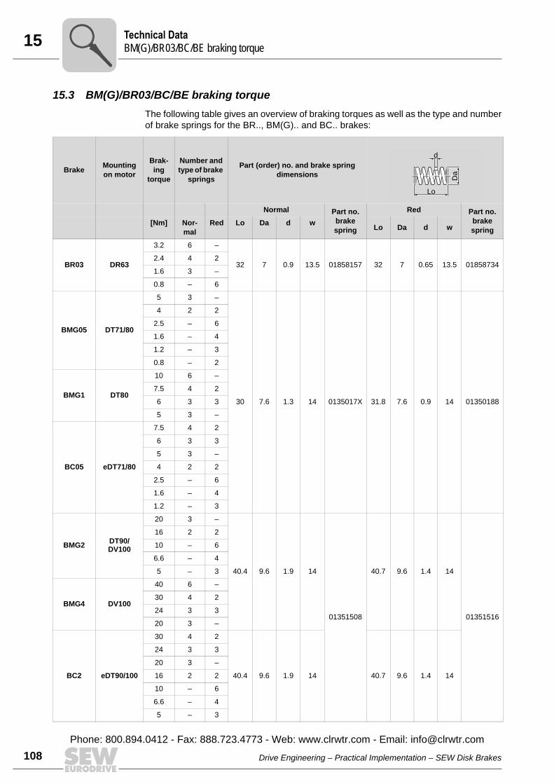
15 echnical DataM(G)/BR03/BC/BE braking torque
108
15.3 BM(G)/BR03/BC/BE braking torqueThe following table gives an overview of braking torques as well as the type and numberof brake springs for the BR.., BM(G).. and BC.. brakes:
Brake Mounting on motor
Brak-ing
torque
Number and type of brake
springs
Part (order) no. and brake spring dimensions
Normal Part no. brake spring
Red Part no. brake spring
[Nm] Nor-mal
Red Lo Da d w Lo Da d w
BR03 DR63
3.2 6 –
32 7 0.9 13.5 01858157 32 7 0.65 13.5 018587342.4 4 2
1.6 3 –
0.8 – 6
BMG05 DT71/80
5 3 –
30 7.6 1.3 14 0135017X 31.8 7.6 0.9 14 01350188
4 2 2
2.5 – 6
1.6 – 4
1.2 – 3
0.8 – 2
BMG1 DT80
10 6 –
7.5 4 2
6 3 3
5 3 –
BC05 eDT71/80
7.5 4 2
6 3 3
5 3 –
4 2 2
2.5 – 6
1.6 – 4
1.2 – 3
BMG2 DT90/DV100
20 3 –
40.4 9.6 1.9 14
01351508
40.7 9.6 1.4 14
01351516
16 2 2
10 – 6
6.6 – 4
5 – 3
BMG4 DV100
40 6 –
30 4 2
24 3 3
20 3 –
BC2 eDT90/100
30 4 2
40.4 9.6 1.9 14 40.7 9.6 1.4 14
24 3 3
20 3 –
16 2 2
10 – 6
6.6 – 4
5 – 3
d
Lo
Da
TB
Drive Engineering – Practical Implementation – SEW Disk Brakes
Phone: 800.894.0412 - Fax: 888.723.4773 - Web: www.clrwtr.com - Email: [email protected]
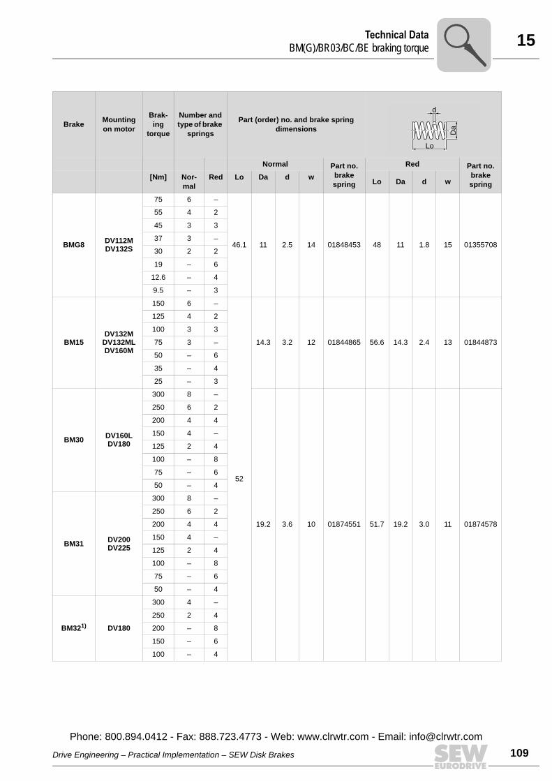
15Technical DataBM(G)/BR03/BC/BE braking torque
BMG8 DV112MDV132S
75 6 –
46.1 11 2.5 14 01848453 48 11 1.8 15 01355708
55 4 2
45 3 3
37 3 –
30 2 2
19 – 6
12.6 – 4
9.5 – 3
BM15DV132M
DV132MLDV160M
150 6 –
52
14.3 3.2 12 01844865 56.6 14.3 2.4 13 01844873
125 4 2
100 3 3
75 3 –
50 – 6
35 – 4
25 – 3
BM30 DV160LDV180
300 8 –
19.2 3.6 10 01874551 51.7 19.2 3.0 11 01874578
250 6 2
200 4 4
150 4 –
125 2 4
100 – 8
75 – 6
50 – 4
BM31 DV200DV225
300 8 –
250 6 2
200 4 4
150 4 –
125 2 4
100 – 8
75 – 6
50 – 4
BM321) DV180
300 4 –
250 2 4
200 – 8
150 – 6
100 – 4
Brake Mounting on motor
Brak-ing
torque
Number and type of brake
springs
Part (order) no. and brake spring dimensions
Normal Part no. brake spring
Red Part no. brake spring
[Nm] Nor-mal
Red Lo Da d w Lo Da d w
d
Lo
Da
Drive Engineering – Practical Implementation – SEW Disk Brakes
Phone: 800.894.0412 - Fax: 888.723.4773 - Web: www.clrwtr.com - Email: info@
109clrwtr.com
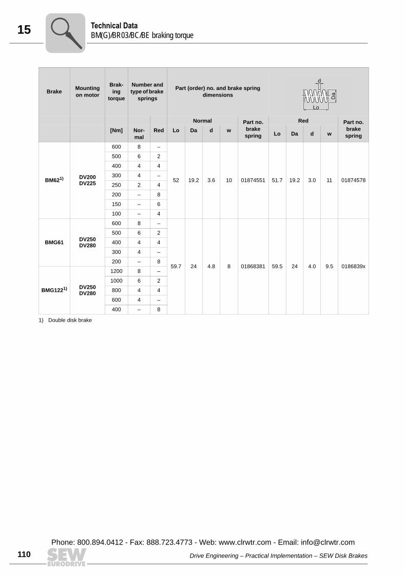
15 echnical DataM(G)/BR03/BC/BE braking torque
110
BM621) DV200DV225
600 8 –
52 19.2 3.6 10 01874551 51.7 19.2 3.0 11 01874578
500 6 2
400 4 4
300 4 –
250 2 4
200 – 8
150 – 6
100 – 4
BMG61 DV250DV280
600 8 –
59.7 24 4.8 8 01868381 59.5 24 4.0 9.5 0186839x
500 6 2
400 4 4
300 4 –
200 – 8
BMG1221) DV250DV280
1200 8 –
1000 6 2
800 4 4
600 4 –
400 – 8
1) Double disk brake
Brake Mounting on motor
Brak-ing
torque
Number and type of brake
springs
Part (order) no. and brake spring dimensions
Normal Part no. brake spring
Red Part no. brake spring
[Nm] Nor-mal
Red Lo Da d w Lo Da d w
d
Lo
Da
TB
Drive Engineering – Practical Implementation – SEW Disk Brakes
Phone: 800.894.0412 - Fax: 888.723.4773 - Web: www.clrwtr.com - Email: [email protected]
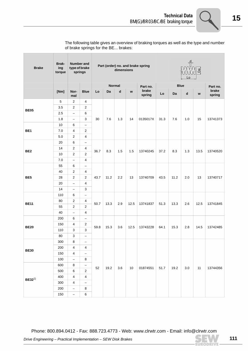
15Technical DataBM(G)/BR03/BC/BE braking torque
The following table gives an overview of braking torques as well as the type and numberof brake springs for the BE... brakes:
BrakeBrak-ing
torque
Number and type of brake
springs
Part (order) no. and brake spring dimensions
Normal Part no. brake spring
Blue Part no. brake spring
[Nm] Nor-mal
Blue Lo Da d w Lo Da d w
BE05
5 2 4
30 7.6 1.3 14 0135017X 31.3 7.6 1.0 15 13741373
3.5 2 2
2.5 – 6
1.8 – 3
BE1
10 6 –
7.0 4 2
5.0 2 4
BE2
20 6 –
36.7 8.3 1.5 1.5 13740245 37.2 8.3 1.3 13.5 1374052014 2 4
10 2 2
7.0 – 4
BE5
55 6 –
43.7 11.2 2.2 13 13740709 43.5 11.2 2.0 13 13740717
40 2 4
28 2 2
20 – 4
14 – 3
BE11
110 6 –
50.7 13.3 2.9 12.5 13741837 51.3 13.3 2.6 12.5 1374184580 2 4
55 2 2
40 – 4
BE20
200 6 –
59.8 15.3 3.6 12.5 13743228 64.1 15.3 2.8 14.5 13742485150 4 2
110 3 3
80 3 –
BE30
300 8 –
52 19.2 3.6 10 01874551 51.7 19.2 3.0 11 13744356
200 4 4
150 4 –
100 – 8
BE321)
600 8 –
500 6 2
400 4 4
300 4 –
200 – 8
150 – 6
d
Lo
Da
Drive Engineering – Practical Implementation – SEW Disk Brakes
Phone: 800.894.0412 - Fax: 888.723.4773 - Web: www.clrwtr.com - Email: info@
111clrwtr.com
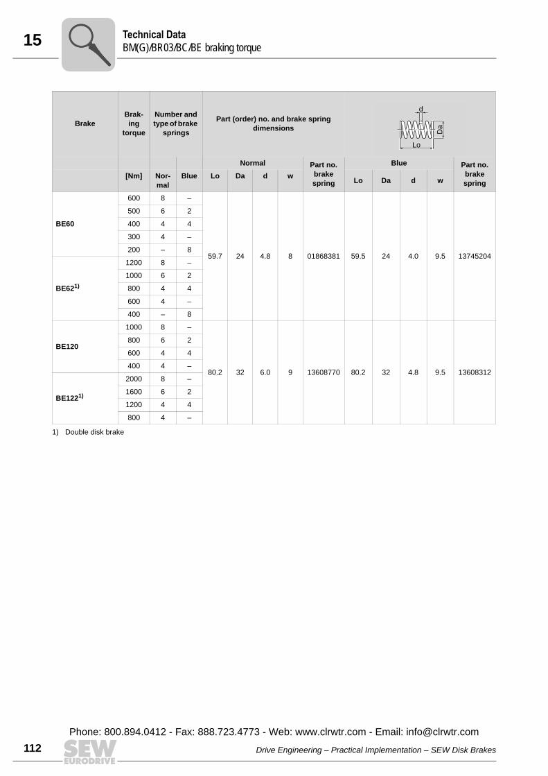
15 echnical DataM(G)/BR03/BC/BE braking torque
112
BE60
600 8 –
59.7 24 4.8 8 01868381 59.5 24 4.0 9.5 13745204
500 6 2
400 4 4
300 4 –
200 – 8
BE621)
1200 8 –
1000 6 2
800 4 4
600 4 –
400 – 8
BE120
1000 8 –
80.2 32 6.0 9 13608770 80.2 32 4.8 9.5 13608312
800 6 2
600 4 4
400 4 –
BE1221)
2000 8 –
1600 6 2
1200 4 4
800 4 –
1) Double disk brake
BrakeBrak-ing
torque
Number and type of brake
springs
Part (order) no. and brake spring dimensions
Normal Part no. brake spring
Blue Part no. brake spring
[Nm] Nor-mal
Blue Lo Da d w Lo Da d w
d
Lo
Da
TB
Drive Engineering – Practical Implementation – SEW Disk Brakes
Phone: 800.894.0412 - Fax: 888.723.4773 - Web: www.clrwtr.com - Email: [email protected]
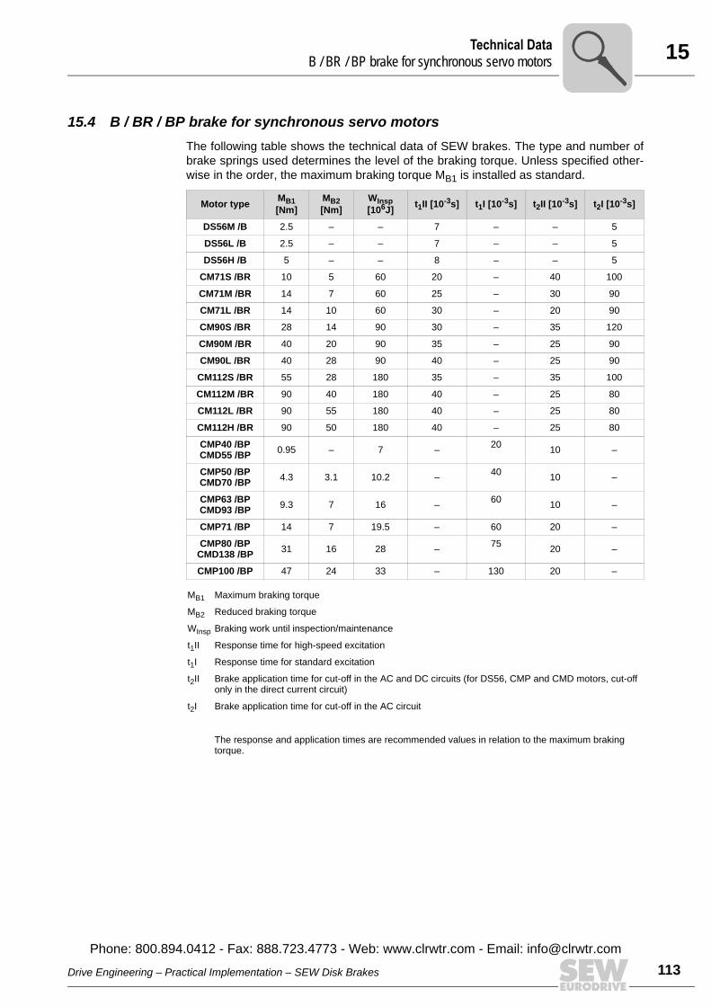
15Technical DataB / BR / BP brake for synchronous servo motors
15.4 B / BR / BP brake for synchronous servo motorsThe following table shows the technical data of SEW brakes. The type and number ofbrake springs used determines the level of the braking torque. Unless specified other-wise in the order, the maximum braking torque MB1 is installed as standard.
Motor type MB1 [Nm]
MB2 [Nm]
WInsp [106J] t1II [10-3s] t1I [10-3s] t2II [10-3s] t2I [10-3s]
DS56M /B 2.5 – – 7 – – 5
DS56L /B 2.5 – – 7 – – 5
DS56H /B 5 – – 8 – – 5
CM71S /BR 10 5 60 20 – 40 100
CM71M /BR 14 7 60 25 – 30 90
CM71L /BR 14 10 60 30 – 20 90
CM90S /BR 28 14 90 30 – 35 120
CM90M /BR 40 20 90 35 – 25 90
CM90L /BR 40 28 90 40 – 25 90
CM112S /BR 55 28 180 35 – 35 100
CM112M /BR 90 40 180 40 – 25 80
CM112L /BR 90 55 180 40 – 25 80
CM112H /BR 90 50 180 40 – 25 80
CMP40 /BPCMD55 /BP 0.95 – 7 – 20 10 –
CMP50 /BPCMD70 /BP 4.3 3.1 10.2 – 40 10 –
CMP63 /BPCMD93 /BP 9.3 7 16 – 60 10 –
CMP71 /BP 14 7 19.5 – 60 20 –
CMP80 /BPCMD138 /BP 31 16 28 – 75 20 –
CMP100 /BP 47 24 33 – 130 20 –
MB1 Maximum braking torque
MB2 Reduced braking torque
WInsp Braking work until inspection/maintenance
t1II Response time for high-speed excitation
t1I Response time for standard excitation
t2II Brake application time for cut-off in the AC and DC circuits (for DS56, CMP and CMD motors, cut-off only in the direct current circuit)
t2I Brake application time for cut-off in the AC circuit
The response and application times are recommended values in relation to the maximum braking torque.
Drive Engineering – Practical Implementation – SEW Disk Brakes
Phone: 800.894.0412 - Fax: 888.723.4773 - Web: www.clrwtr.com - Email: info@
113clrwtr.com
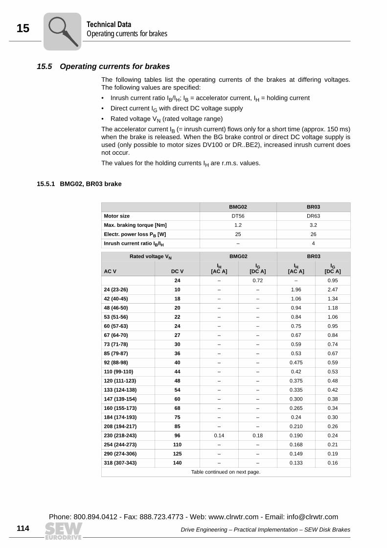
15 echnical Dataperating currents for brakes
114
15.5 Operating currents for brakesThe following tables list the operating currents of the brakes at differing voltages.The following values are specified:• Inrush current ratio IB/IH; IB = accelerator current, IH = holding current• Direct current IG with direct DC voltage supply• Rated voltage VN (rated voltage range)The accelerator current IB (= inrush current) flows only for a short time (approx. 150 ms)when the brake is released. When the BG brake control or direct DC voltage supply isused (only possible to motor sizes DV100 or DR..BE2), increased inrush current doesnot occur.The values for the holding currents IH are r.m.s. values.
15.5.1 BMG02, BR03 brake
BMG02 BR03
Motor size DT56 DR63
Max. braking torque [Nm] 1.2 3.2
Electr. power loss PB [W] 25 26
Inrush current ratio IB/IH – 4
Rated voltage VN BMG02 BR03
IH[AC A]
IG[DC A]
IH[AC A]
IG[DC A]AC V DC V
24 – 0.72 – 0.95
24 (23-26) 10 – – 1.96 2.47
42 (40-45) 18 – – 1.06 1.34
48 (46-50) 20 – – 0.94 1.18
53 (51-56) 22 – – 0.84 1.06
60 (57-63) 24 – – 0.75 0.95
67 (64-70) 27 – – 0.67 0.84
73 (71-78) 30 – – 0.59 0.74
85 (79-87) 36 – – 0.53 0.67
92 (88-98) 40 – – 0.475 0.59
110 (99-110) 44 – – 0.42 0.53
120 (111-123) 48 – – 0.375 0.48
133 (124-138) 54 – – 0.335 0.42
147 (139-154) 60 – – 0.300 0.38
160 (155-173) 68 – – 0.265 0.34
184 (174-193) 75 – – 0.24 0.30
208 (194-217) 85 – – 0.210 0.26
230 (218-243) 96 0.14 0.18 0.190 0.24
254 (244-273) 110 – – 0.168 0.21
290 (274-306) 125 – – 0.149 0.19
318 (307-343) 140 – – 0.133 0.16
Table continued on next page.
TO
Drive Engineering – Practical Implementation – SEW Disk Brakes
Phone: 800.894.0412 - Fax: 888.723.4773 - Web: www.clrwtr.com - Email: [email protected]
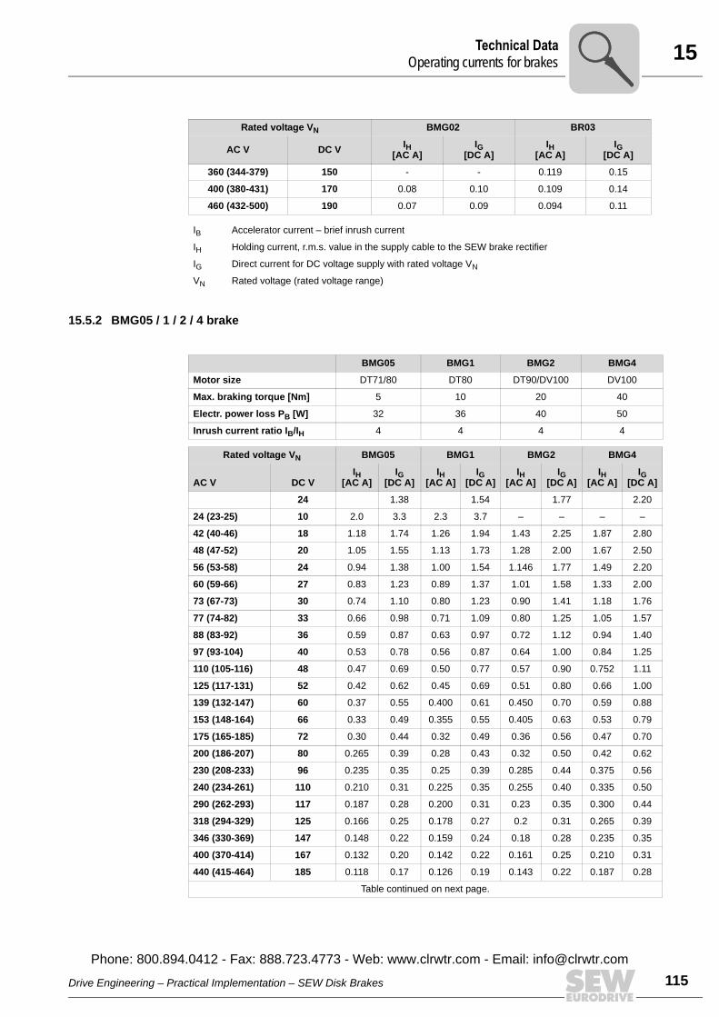
15Technical DataOperating currents for brakes
15.5.2 BMG05 / 1 / 2 / 4 brake
Rated voltage VN BMG02 BR03
IH[AC A]
IG[DC A]
IH[AC A]
IG[DC A]AC V DC V
360 (344-379) 150 - - 0.119 0.15
400 (380-431) 170 0.08 0.10 0.109 0.14
460 (432-500) 190 0.07 0.09 0.094 0.11
IB Accelerator current – brief inrush current
IH Holding current, r.m.s. value in the supply cable to the SEW brake rectifier
IG Direct current for DC voltage supply with rated voltage VN
VN Rated voltage (rated voltage range)
BMG05 BMG1 BMG2 BMG4
Motor size DT71/80 DT80 DT90/DV100 DV100
Max. braking torque [Nm] 5 10 20 40
Electr. power loss PB [W] 32 36 40 50
Inrush current ratio IB/IH 4 4 4 4
Rated voltage VN BMG05 BMG1 BMG2 BMG4
IH[AC A]
IG[DC A]
IH[AC A]
IG[DC A]
IH[AC A]
IG[DC A]
IH[AC A]
IG[DC A]AC V DC V
24 1.38 1.54 1.77 2.20
24 (23-25) 10 2.0 3.3 2.3 3.7 – – – –
42 (40-46) 18 1.18 1.74 1.26 1.94 1.43 2.25 1.87 2.80
48 (47-52) 20 1.05 1.55 1.13 1.73 1.28 2.00 1.67 2.50
56 (53-58) 24 0.94 1.38 1.00 1.54 1.146 1.77 1.49 2.20
60 (59-66) 27 0.83 1.23 0.89 1.37 1.01 1.58 1.33 2.00
73 (67-73) 30 0.74 1.10 0.80 1.23 0.90 1.41 1.18 1.76
77 (74-82) 33 0.66 0.98 0.71 1.09 0.80 1.25 1.05 1.57
88 (83-92) 36 0.59 0.87 0.63 0.97 0.72 1.12 0.94 1.40
97 (93-104) 40 0.53 0.78 0.56 0.87 0.64 1.00 0.84 1.25
110 (105-116) 48 0.47 0.69 0.50 0.77 0.57 0.90 0.752 1.11
125 (117-131) 52 0.42 0.62 0.45 0.69 0.51 0.80 0.66 1.00
139 (132-147) 60 0.37 0.55 0.400 0.61 0.450 0.70 0.59 0.88
153 (148-164) 66 0.33 0.49 0.355 0.55 0.405 0.63 0.53 0.79
175 (165-185) 72 0.30 0.44 0.32 0.49 0.36 0.56 0.47 0.70
200 (186-207) 80 0.265 0.39 0.28 0.43 0.32 0.50 0.42 0.62
230 (208-233) 96 0.235 0.35 0.25 0.39 0.285 0.44 0.375 0.56
240 (234-261) 110 0.210 0.31 0.225 0.35 0.255 0.40 0.335 0.50
290 (262-293) 117 0.187 0.28 0.200 0.31 0.23 0.35 0.300 0.44
318 (294-329) 125 0.166 0.25 0.178 0.27 0.2 0.31 0.265 0.39
346 (330-369) 147 0.148 0.22 0.159 0.24 0.18 0.28 0.235 0.35
400 (370-414) 167 0.132 0.20 0.142 0.22 0.161 0.25 0.210 0.31
440 (415-464) 185 0.118 0.17 0.126 0.19 0.143 0.22 0.187 0.28
Table continued on next page.
Drive Engineering – Practical Implementation – SEW Disk Brakes
Phone: 800.894.0412 - Fax: 888.723.4773 - Web: www.clrwtr.com - Email: info@
115clrwtr.com

15 echnical Dataperating currents for brakes
116
15.5.3 BMG8, BM15 / 30 / 31 / 32 / 62 brake
Rated voltage VN BMG05 BMG1 BMG2 BMG4
IH[AC A]
IG[DC A]
IH[AC A]
IG[DC A]
IH[AC A]
IG[DC A]
IH[AC A]
IG[DC A]AC V DC V
500 (465-522) 208 0.105 0.15 0.113 0.17 0.128 0.20 0.167 0.25
575 (523-585) 233 0.094 0.14 0.10 0.15 0.114 0.17 0.149 0.22
IB Accelerator current – brief inrush current
IH Holding current, r.m.s. value in the supply cable to the SEW brake rectifier
IG Direct current with direct DC voltage supply
VN Rated voltage (rated voltage range)
BMG8 BM15 BM30 / 31; BM32 / 62
Motor size DV112/132S DV132M-160M DV160L-225
Max. braking torque [Nm] 75 150 600
Electr. power loss PB [W] 70 95 120
Inrush current ratio IB/IH 6.3 7.5 8.5
Rated voltage VN BMG8 BM15 BM30 / 31; BM32 / 62IH
[AC A]IH
[AC A]IH
[AC A]AC V DC V24 2.771)
1) Direct current for operation with BSG
4.151) 4.001)
42 (40-46) – 2.31 3.35 –48 (47-52) – 2.10 2.95 –56 (53-58) – 1.84 2.65 –60 (59-66) – 1.64 2.35 –73 (67-73) – 1.46 2.10 –77 (74-82) – 1.30 1.87 –88 (83-92) – 1.16 1.67 –97 (93-104) – 1.04 1.49 –110 (105-116) – 0.93 1.32 1.78125 (117-131) – 0.82 1.18 1.60139 (132-147) – 0.73 1.05 1.43153 (148-164) – 0.66 0.94 1.27175 (165-185) – 0.59 0.84 1.13200 (186-207) – 0.52 0.74 1.00230 (208-233) – 0.46 0.66 0.90240 (234-261) – 0.41 0.59 0.80290 (262-293) – 0.36 0.53 0.71318 (294-329) – 0.33 0.47 0.63346 (330-369) – 0.29 0.42 0.57400 (370-414) – 0.26 0.37 0.50440 (415-464) – 0.24 0.33 0.44500 (465-522) – 0.20 0.30 0.40575 (523-585) – 0.18 0.26 0.36
IH Holding current, r.m.s. value in the supply cable to the SEW brake rectifier
IB Accelerator current – brief inrush current
VN Rated voltage (rated voltage range)
TO
Drive Engineering – Practical Implementation – SEW Disk Brakes
Phone: 800.894.0412 - Fax: 888.723.4773 - Web: www.clrwtr.com - Email: [email protected]
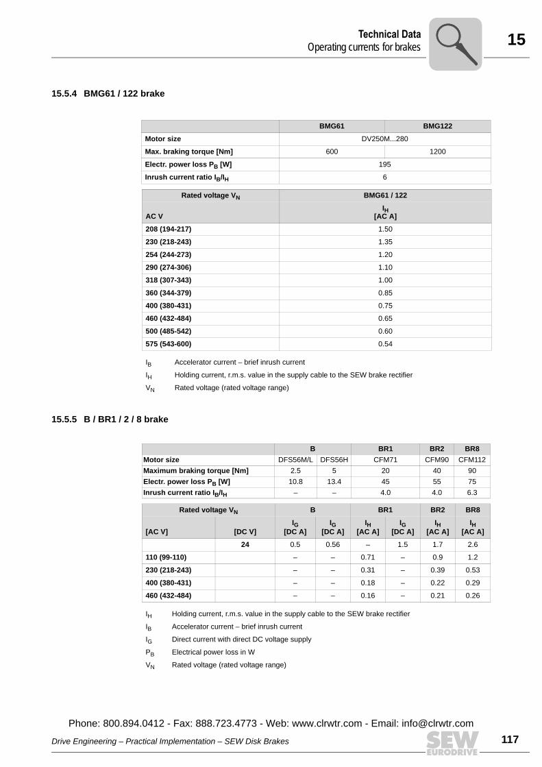
15Technical DataOperating currents for brakes
15.5.4 BMG61 / 122 brake
15.5.5 B / BR1 / 2 / 8 brake
BMG61 BMG122
Motor size DV250M...280
Max. braking torque [Nm] 600 1200
Electr. power loss PB [W] 195
Inrush current ratio IB/IH 6
Rated voltage VN BMG61 / 122
IH[AC A]AC V
208 (194-217) 1.50
230 (218-243) 1.35
254 (244-273) 1.20
290 (274-306) 1.10
318 (307-343) 1.00
360 (344-379) 0.85
400 (380-431) 0.75
460 (432-484) 0.65
500 (485-542) 0.60
575 (543-600) 0.54
IB Accelerator current – brief inrush current
IH Holding current, r.m.s. value in the supply cable to the SEW brake rectifier
VN Rated voltage (rated voltage range)
B BR1 BR2 BR8Motor size DFS56M/L DFS56H CFM71 CFM90 CFM112Maximum braking torque [Nm] 2.5 5 20 40 90Electr. power loss PB [W] 10.8 13.4 45 55 75Inrush current ratio IB/IH – – 4.0 4.0 6.3
Rated voltage VN B BR1 BR2 BR8
[AC V] [DC V]IG
[DC A]IG
[DC A]IH
[AC A]IG
[DC A]IH
[AC A]IH
[AC A]
24 0.5 0.56 – 1.5 1.7 2.6
110 (99-110) – – 0.71 – 0.9 1.2
230 (218-243) – – 0.31 – 0.39 0.53
400 (380-431) – – 0.18 – 0.22 0.29
460 (432-484) – – 0.16 – 0.21 0.26
IH Holding current, r.m.s. value in the supply cable to the SEW brake rectifier
IB Accelerator current – brief inrush current
IG Direct current with direct DC voltage supply
PB Electrical power loss in W
VN Rated voltage (rated voltage range)
Drive Engineering – Practical Implementation – SEW Disk Brakes
Phone: 800.894.0412 - Fax: 888.723.4773 - Web: www.clrwtr.com - Email: info@
117clrwtr.com
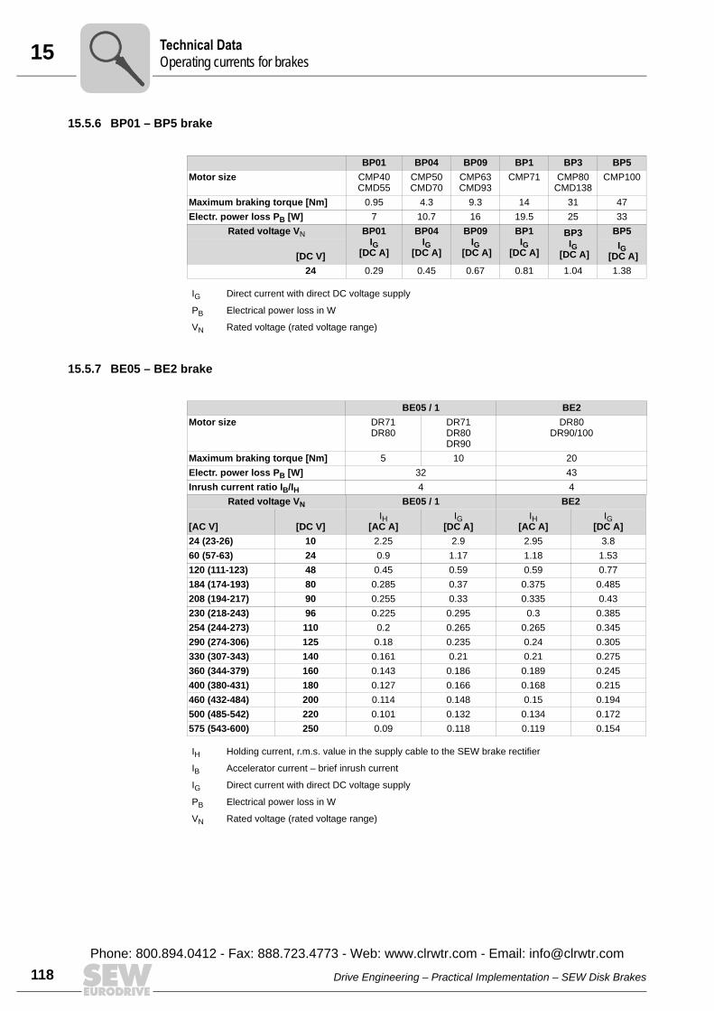
15 echnical Dataperating currents for brakes
118
15.5.6 BP01 – BP5 brake
15.5.7 BE05 – BE2 brake
BP01 BP04 BP09 BP1 BP3 BP5Motor size CMP40
CMD55CMP50CMD70
CMP63CMD93
CMP71 CMP80CMD138
CMP100
Maximum braking torque [Nm] 0.95 4.3 9.3 14 31 47Electr. power loss PB [W] 7 10.7 16 19.5 25 33
Rated voltage VN BP01IG
[DC A]
BP04IG
[DC A]
BP09IG
[DC A]
BP1IG
[DC A]
BP3IG
[DC A]
BP5
[DC V]IG
[DC A]24 0.29 0.45 0.67 0.81 1.04 1.38
IG Direct current with direct DC voltage supply
PB Electrical power loss in W
VN Rated voltage (rated voltage range)
BE05 / 1 BE2Motor size DR71
DR80 DR71DR80DR90
DR80DR90/100
Maximum braking torque [Nm] 5 10 20Electr. power loss PB [W] 32 43Inrush current ratio IB/IH 4 4
Rated voltage VN BE05 / 1 BE2
[AC V] [DC V]IH
[AC A]IG
[DC A]IH
[AC A]IG
[DC A]24 (23-26) 10 2.25 2.9 2.95 3.860 (57-63) 24 0.9 1.17 1.18 1.53120 (111-123) 48 0.45 0.59 0.59 0.77184 (174-193) 80 0.285 0.37 0.375 0.485208 (194-217) 90 0.255 0.33 0.335 0.43230 (218-243) 96 0.225 0.295 0.3 0.385254 (244-273) 110 0.2 0.265 0.265 0.345290 (274-306) 125 0.18 0.235 0.24 0.305330 (307-343) 140 0.161 0.21 0.21 0.275360 (344-379) 160 0.143 0.186 0.189 0.245400 (380-431) 180 0.127 0.166 0.168 0.215460 (432-484) 200 0.114 0.148 0.15 0.194500 (485-542) 220 0.101 0.132 0.134 0.172575 (543-600) 250 0.09 0.118 0.119 0.154
IH Holding current, r.m.s. value in the supply cable to the SEW brake rectifier
IB Accelerator current – brief inrush current
IG Direct current with direct DC voltage supply
PB Electrical power loss in W
VN Rated voltage (rated voltage range)
TO
Drive Engineering – Practical Implementation – SEW Disk Brakes
Phone: 800.894.0412 - Fax: 888.723.4773 - Web: www.clrwtr.com - Email: [email protected]
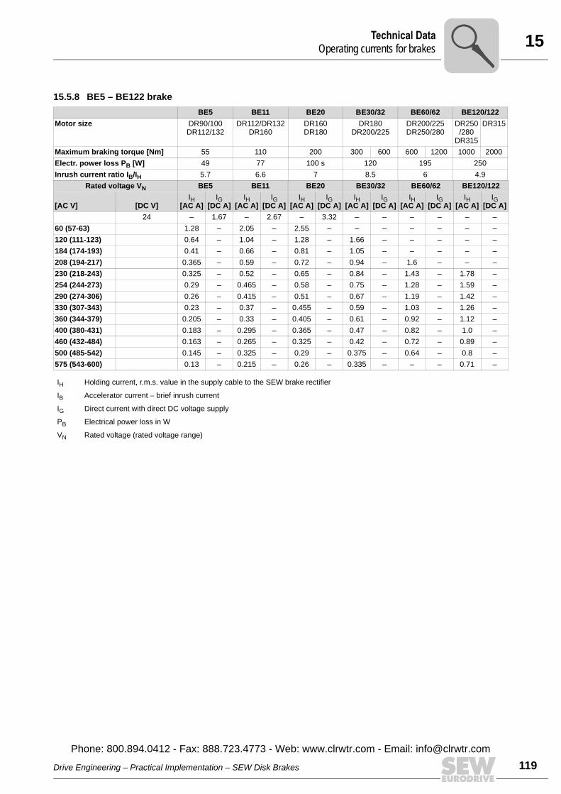
15Technical DataOperating currents for brakes
15.5.8 BE5 – BE122 brakeBE5 BE11 BE20 BE30/32 BE60/62 BE120/122
Motor size DR90/100DR112/132
DR112/DR132DR160
DR160DR180
DR180DR200/225
DR200/225 DR250/280
DR250/280
DR315
DR315
Maximum braking torque [Nm] 55 110 200 300 600 600 1200 1000 2000Electr. power loss PB [W] 49 77 100 s 120 195 250Inrush current ratio IB/IH 5.7 6.6 7 8.5 6 4.9
Rated voltage VN BE5 BE11 BE20 BE30/32 BE60/62 BE120/122
[AC V] [DC V]IH
[AC A]IG
[DC A]IH
[AC A]IG
[DC A]IH
[AC A]IG
[DC A]IH
[AC A]IG
[DC A]IH
[AC A]IG
[DC A]IH
[AC A]IG
[DC A]24 – 1.67 – 2.67 – 3.32 – – – – – –
60 (57-63) 1.28 – 2.05 – 2.55 – – – – – – –120 (111-123) 0.64 – 1.04 – 1.28 – 1.66 – – – – –184 (174-193) 0.41 – 0.66 – 0.81 – 1.05 – – – – –208 (194-217) 0.365 – 0.59 – 0.72 – 0.94 – 1.6 – – –230 (218-243) 0.325 – 0.52 – 0.65 – 0.84 – 1.43 – 1.78 –254 (244-273) 0.29 – 0.465 – 0.58 – 0.75 – 1.28 – 1.59 –290 (274-306) 0.26 – 0.415 – 0.51 – 0.67 – 1.19 – 1.42 –330 (307-343) 0.23 – 0.37 – 0.455 – 0.59 – 1.03 – 1.26 –360 (344-379) 0.205 – 0.33 – 0.405 – 0.61 – 0.92 – 1.12 –400 (380-431) 0.183 – 0.295 – 0.365 – 0.47 – 0.82 – 1.0 –460 (432-484) 0.163 – 0.265 – 0.325 – 0.42 – 0.72 – 0.89 –500 (485-542) 0.145 – 0.325 – 0.29 – 0.375 – 0.64 – 0.8 –575 (543-600) 0.13 – 0.215 – 0.26 – 0.335 – – – 0.71 –
IH Holding current, r.m.s. value in the supply cable to the SEW brake rectifier
IB Accelerator current – brief inrush current
IG Direct current with direct DC voltage supply
PB Electrical power loss in W
VN Rated voltage (rated voltage range)
Drive Engineering – Practical Implementation – SEW Disk Brakes
Phone: 800.894.0412 - Fax: 888.723.4773 - Web: www.clrwtr.com - Email: info@
119clrwtr.com
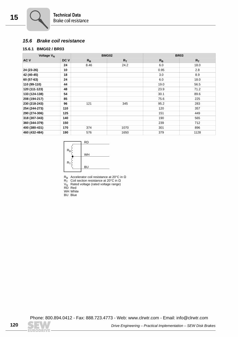
15 echnical Datarake coil resistance
120
15.6 Brake coil resistance15.6.1 BMG02 / BR03
Voltage VN BMG02 BR03AC V DC V RB RT RB RT
24 8.46 24.2 6.0 18.024 (23-26) 10 0.95 2.842 (40-45) 18 3.0 8.960 (57-63) 24 6.0 18.0110 (99-110) 44 19.0 56.5120 (111-123) 48 23.9 71.2133 (124-138) 54 30.1 89.6208 (194-217) 85 75.6 225230 (218-243) 96 121 345 95.2 283254 (244-273) 110 120 357290 (274-306) 125 151 449318 (307-343) 140 190 565360 (344-379) 150 239 712400 (380-431) 170 374 1070 301 896460 (432-484) 190 576 1650 379 1128
RB Accelerator coil resistance at 20°C in ÊRT Coil section resistance at 20°C in ÊVN Rated voltage (rated voltage range)RD RedWH WhiteBU Blue
RB
RD
WH
BU
RT
TB
Drive Engineering – Practical Implementation – SEW Disk Brakes
Phone: 800.894.0412 - Fax: 888.723.4773 - Web: www.clrwtr.com - Email: [email protected]
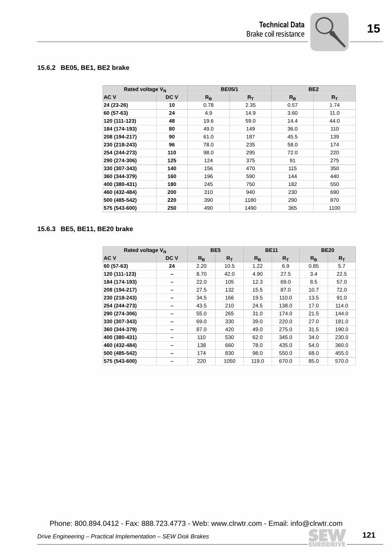
15Technical DataBrake coil resistance
15.6.2 BE05, BE1, BE2 brake
15.6.3 BE5, BE11, BE20 brake
Rated voltage VN BE05/1 BE2RB RT RB RTAC V DC V
24 (23-26) 10 0.78 2.35 0.57 1.7460 (57-63) 24 4.9 14.9 3.60 11.0120 (111-123) 48 19.6 59.0 14.4 44.0184 (174-193) 80 49.0 149 36.0 110208 (194-217) 90 61.0 187 45.5 139230 (218-243) 96 78.0 235 58.0 174254 (244-273) 110 98.0 295 72.0 220290 (274-306) 125 124 375 91 275330 (307-343) 140 156 470 115 350360 (344-379) 160 196 590 144 440400 (380-431) 180 245 750 182 550460 (432-484) 200 310 940 230 690500 (485-542) 220 390 1180 290 870575 (543-600) 250 490 1490 365 1100
Rated voltage VN BE5 BE11 BE20RB RT RB RT RB RTAC V DC V
60 (57-63) 24 2.20 10.5 1.22 6.9 0.85 5.7120 (111-123) – 8.70 42.0 4.90 27.5 3.4 22.5184 (174-193) – 22.0 105 12.3 69.0 8.5 57.0208 (194-217) – 27.5 132 15.5 87.0 10.7 72.0230 (218-243) – 34.5 166 19.5 110.0 13.5 91.0254 (244-273) – 43.5 210 24.5 138.0 17.0 114.0290 (274-306) – 55.0 265 31.0 174.0 21.5 144.0330 (307-343) – 69.0 330 39.0 220.0 27.0 181.0360 (344-379) – 87.0 420 49.0 275.0 31.5 190.0400 (380-431) – 110 530 62.0 345.0 34.0 230.0460 (432-484) – 138 660 78.0 435.0 54.0 360.0500 (485-542) – 174 830 98.0 550.0 68.0 455.0575 (543-600) – 220 1050 119.0 670.0 85.0 570.0
Drive Engineering – Practical Implementation – SEW Disk Brakes
Phone: 800.894.0412 - Fax: 888.723.4773 - Web: www.clrwtr.com - Email: info@
121clrwtr.com
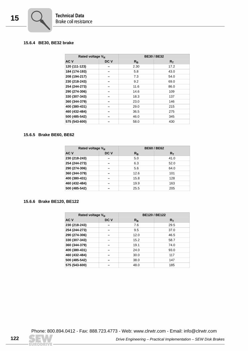
15 echnical Datarake coil resistance
122
15.6.4 BE30, BE32 brake
15.6.5 Brake BE60, BE62
15.6.6 Brake BE120, BE122
Rated voltage VN BE30 / BE32RB RTAC V DC V
120 (111-123) – 2.30 17.2184 (174-193) – 5.8 43.0208 (194-217) – 7.3 54.0230 (218-243) – 9.2 69.0254 (244-273) – 11.6 86.0290 (274-306) – 14.6 109330 (307-343) – 18.3 137360 (344-379) – 23.0 146400 (380-431) – 29.0 215460 (432-484) – 36.5 275500 (485-542) – 46.0 345575 (543-600) – 58.0 430
Rated voltage VN BE60 / BE62AC V DC V RB RT230 (218-243) – 5.0 41.0254 (244-273) – 6.3 52.0290 (274-306) – 5.6 64.0360 (344-379) – 12.6 101400 (380-431) – 15.8 128460 (432-484) – 19.9 163500 (485-542) – 25.5 205
Rated voltage VN BE120 / BE122RB RTAC V DC V
230 (218-243) – 7.6 29.5254 (244-273) – 9.5 37.0290 (274-306) – 12.0 46.5330 (307-343) – 15.2 58.7360 (344-379) – 19.1 74.0400 (380-431) – 24.0 93.0460 (432-484) – 30.0 117500 (485-542) – 38.0 147575 (543-600) – 48.0 185
TB
Drive Engineering – Practical Implementation – SEW Disk Brakes
Phone: 800.894.0412 - Fax: 888.723.4773 - Web: www.clrwtr.com - Email: [email protected]
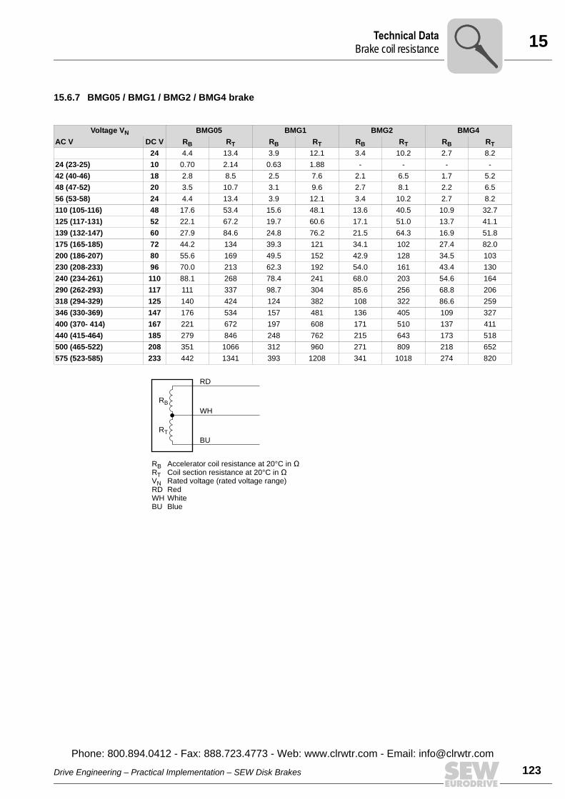
15Technical DataBrake coil resistance
15.6.7 BMG05 / BMG1 / BMG2 / BMG4 brake
Voltage VN BMG05 BMG1 BMG2 BMG4AC V DC V RB RT RB RT RB RT RB RT
24 4.4 13.4 3.9 12.1 3.4 10.2 2.7 8.224 (23-25) 10 0.70 2.14 0.63 1.88 - - - -42 (40-46) 18 2.8 8.5 2.5 7.6 2.1 6.5 1.7 5.248 (47-52) 20 3.5 10.7 3.1 9.6 2.7 8.1 2.2 6.556 (53-58) 24 4.4 13.4 3.9 12.1 3.4 10.2 2.7 8.2110 (105-116) 48 17.6 53.4 15.6 48.1 13.6 40.5 10.9 32.7125 (117-131) 52 22.1 67.2 19.7 60.6 17.1 51.0 13.7 41.1139 (132-147) 60 27.9 84.6 24.8 76.2 21.5 64.3 16.9 51.8175 (165-185) 72 44.2 134 39.3 121 34.1 102 27.4 82.0200 (186-207) 80 55.6 169 49.5 152 42.9 128 34.5 103230 (208-233) 96 70.0 213 62.3 192 54.0 161 43.4 130240 (234-261) 110 88.1 268 78.4 241 68.0 203 54.6 164290 (262-293) 117 111 337 98.7 304 85.6 256 68.8 206318 (294-329) 125 140 424 124 382 108 322 86.6 259346 (330-369) 147 176 534 157 481 136 405 109 327400 (370- 414) 167 221 672 197 608 171 510 137 411440 (415-464) 185 279 846 248 762 215 643 173 518500 (465-522) 208 351 1066 312 960 271 809 218 652575 (523-585) 233 442 1341 393 1208 341 1018 274 820
RB Accelerator coil resistance at 20°C in ÊRT Coil section resistance at 20°C in ÊVN Rated voltage (rated voltage range)RD RedWH WhiteBU Blue
RB
RD
WH
BU
RT
Drive Engineering – Practical Implementation – SEW Disk Brakes
Phone: 800.894.0412 - Fax: 888.723.4773 - Web: www.clrwtr.com - Email: info@
123clrwtr.com
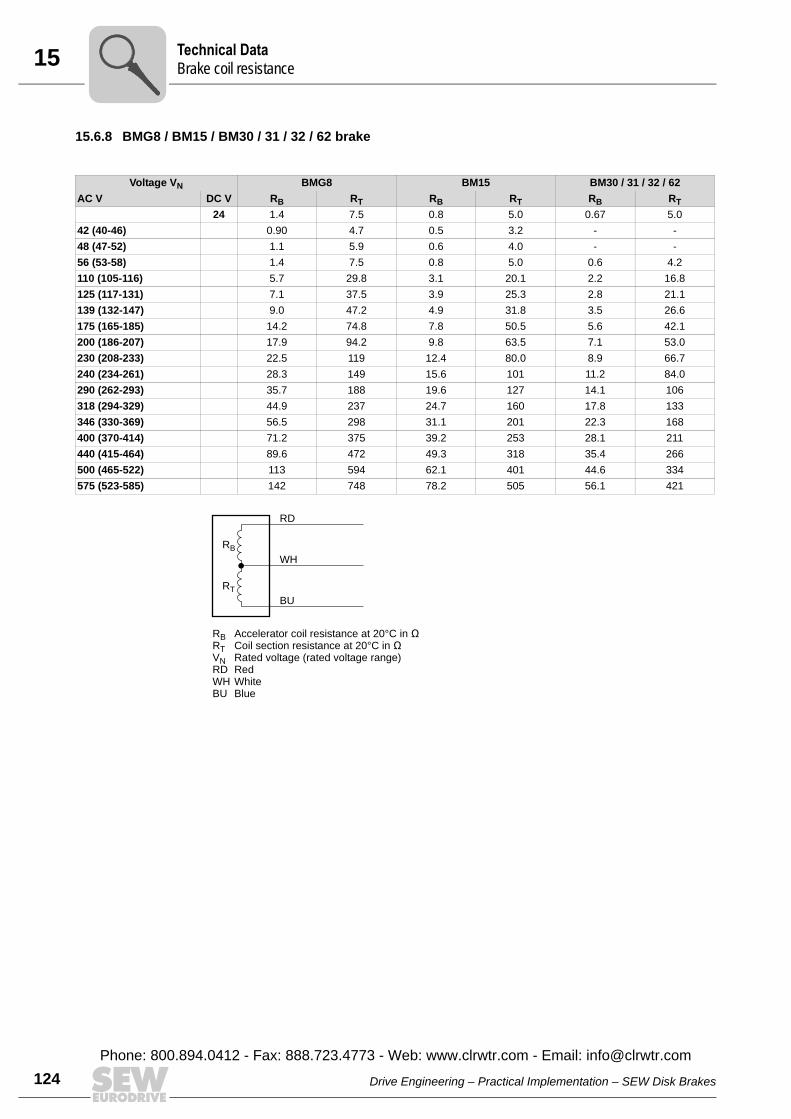
15 echnical Datarake coil resistance
124
15.6.8 BMG8 / BM15 / BM30 / 31 / 32 / 62 brake
Voltage VN BMG8 BM15 BM30 / 31 / 32 / 62AC V DC V RB RT RB RT RB RT
24 1.4 7.5 0.8 5.0 0.67 5.042 (40-46) 0.90 4.7 0.5 3.2 - -48 (47-52) 1.1 5.9 0.6 4.0 - -56 (53-58) 1.4 7.5 0.8 5.0 0.6 4.2110 (105-116) 5.7 29.8 3.1 20.1 2.2 16.8125 (117-131) 7.1 37.5 3.9 25.3 2.8 21.1139 (132-147) 9.0 47.2 4.9 31.8 3.5 26.6175 (165-185) 14.2 74.8 7.8 50.5 5.6 42.1200 (186-207) 17.9 94.2 9.8 63.5 7.1 53.0230 (208-233) 22.5 119 12.4 80.0 8.9 66.7240 (234-261) 28.3 149 15.6 101 11.2 84.0290 (262-293) 35.7 188 19.6 127 14.1 106318 (294-329) 44.9 237 24.7 160 17.8 133346 (330-369) 56.5 298 31.1 201 22.3 168400 (370-414) 71.2 375 39.2 253 28.1 211440 (415-464) 89.6 472 49.3 318 35.4 266500 (465-522) 113 594 62.1 401 44.6 334575 (523-585) 142 748 78.2 505 56.1 421
RB Accelerator coil resistance at 20°C in ÊRT Coil section resistance at 20°C in ÊVN Rated voltage (rated voltage range)RD RedWH WhiteBU Blue
RB
RD
WH
BU
RT
TB
Drive Engineering – Practical Implementation – SEW Disk Brakes
Phone: 800.894.0412 - Fax: 888.723.4773 - Web: www.clrwtr.com - Email: [email protected]
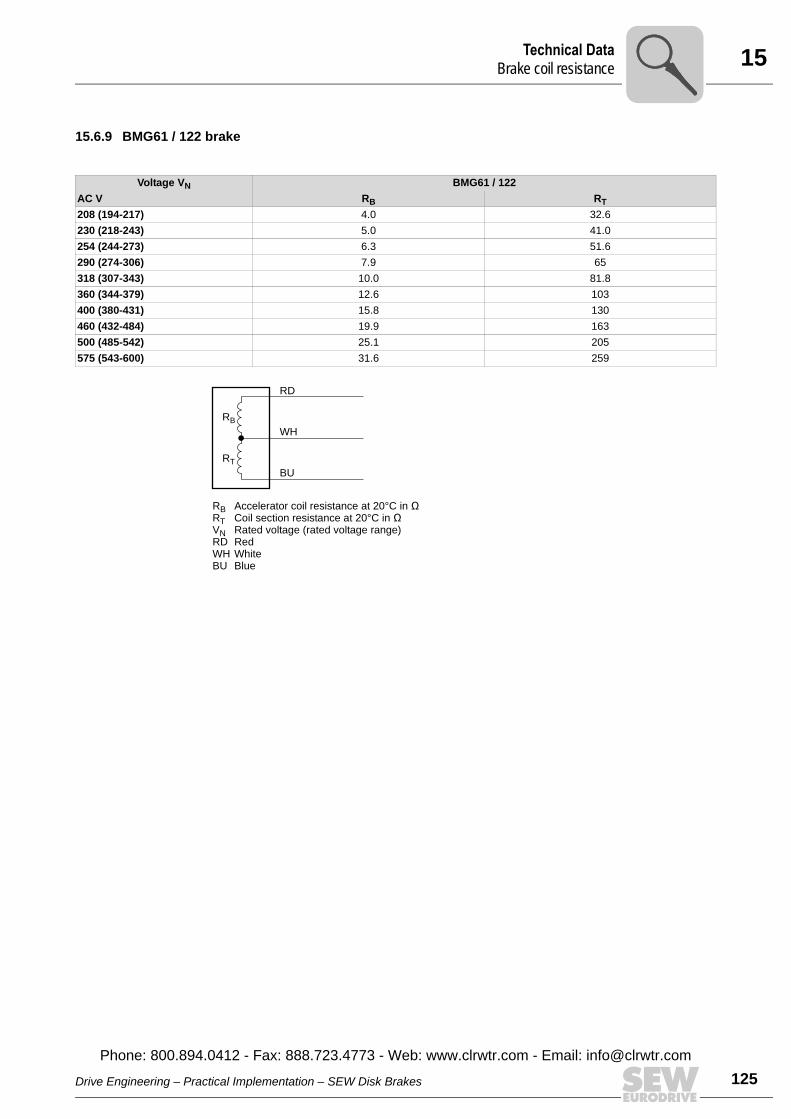
15Technical DataBrake coil resistance
15.6.9 BMG61 / 122 brake
Voltage VN BMG61 / 122AC V RB RT208 (194-217) 4.0 32.6230 (218-243) 5.0 41.0254 (244-273) 6.3 51.6290 (274-306) 7.9 65318 (307-343) 10.0 81.8360 (344-379) 12.6 103400 (380-431) 15.8 130460 (432-484) 19.9 163500 (485-542) 25.1 205575 (543-600) 31.6 259
RB Accelerator coil resistance at 20°C in ÊRT Coil section resistance at 20°C in ÊVN Rated voltage (rated voltage range)RD RedWH WhiteBU Blue
RB
RD
WH
BU
RT
Drive Engineering – Practical Implementation – SEW Disk Brakes
Phone: 800.894.0412 - Fax: 888.723.4773 - Web: www.clrwtr.com - Email: info@
125clrwtr.com
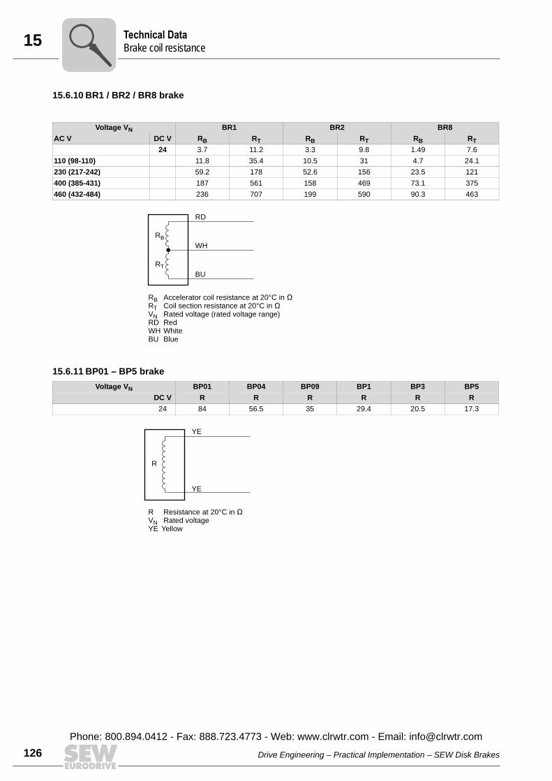
15 echnical Datarake coil resistance
126
15.6.10 BR1 / BR2 / BR8 brake
15.6.11 BP01 – BP5 brake
Voltage VN BR1 BR2 BR8AC V DC V RB RT RB RT RB RT
24 3.7 11.2 3.3 9.8 1.49 7.6110 (98-110) 11.8 35.4 10.5 31 4.7 24.1230 (217-242) 59.2 178 52.6 156 23.5 121400 (385-431) 187 561 158 469 73.1 375460 (432-484) 236 707 199 590 90.3 463
RB Accelerator coil resistance at 20°C in ÊRT Coil section resistance at 20°C in ÊVN Rated voltage (rated voltage range)RD RedWH WhiteBU Blue
RB
RD
WH
BU
RT
Voltage VN BP01 BP04 BP09 BP1 BP3 BP5DC V R R R R R R
24 84 56.5 35 29.4 20.5 17.3
R Resistance at 20°C in ÊVN Rated voltageYE Yellow
R
YE
YE
TB
Drive Engineering – Practical Implementation – SEW Disk Brakes
Phone: 800.894.0412 - Fax: 888.723.4773 - Web: www.clrwtr.com - Email: [email protected]
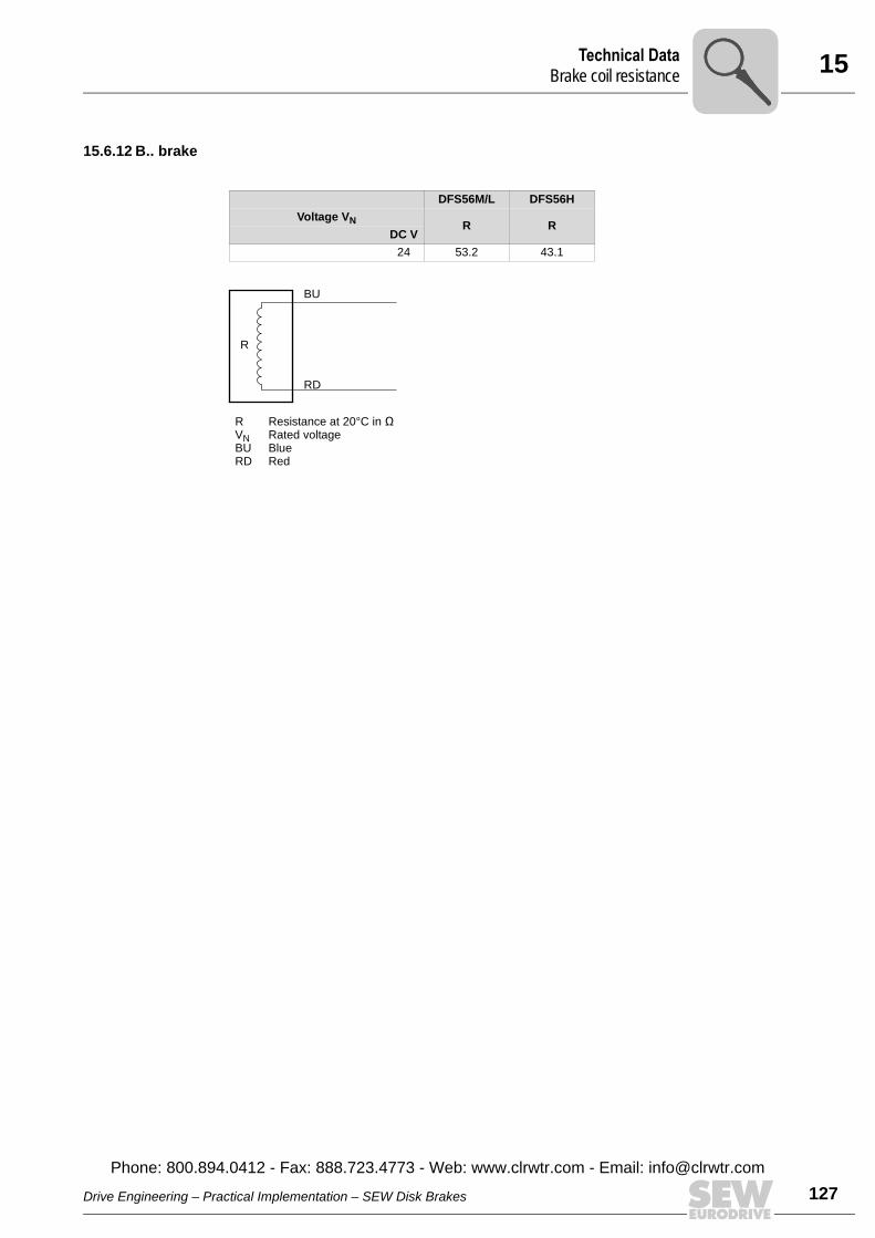
15Technical DataBrake coil resistance
15.6.12 B.. brake
DFS56M/L DFS56HVoltage VN R R
DC V24 53.2 43.1
RVNBURD
Resistance at 20°C in ÊRated voltageBlueRed
R
BU
RD
Drive Engineering – Practical Implementation – SEW Disk Brakes
Phone: 800.894.0412 - Fax: 888.723.4773 - Web: www.clrwtr.com - Email: info@
127clrwtr.com
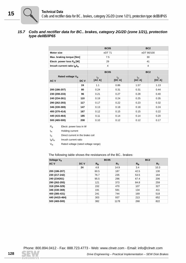
15 echnical Dataoils and rectifier data for BC.. brakes, category 2G/2D (zone 1/21), protection type deIIB/IP65
128
15.7 Coils and rectifier data for BC.. brakes, category 2G/2D (zone 1/21), protection type deIIB/IP65
The following table shows the resistances of the BC.. brakes:
BC05 BC2
Motor size eDT 71 eDT 90/100
Max. braking torque [Nm] 7.5 30
Electr. power loss PB [W] 29 41
Inrush current ratio IB/IH 4 4
BC05 BC2
Rated voltage VN IH[AC A]
IG[DC A]
IH[AC A]
IG[DC A]AC V DC V
24 1.1 0.86 1.57 1.13
200 (186-207) 80 0.24 0.31 0.31 0.44
230 (208-233) 96 0.21 0.27 0.28 0.40
240 (234-261) 110 0.19 0.24 0.25 0.35
290 (262-293) 117 0.17 0.22 0.23 0.32
346 (330-369) 147 0.13 0.18 0.18 0.24
400 (370-414) 167 0.12 0.15 0.15 0.22
440 (415-464) 185 0.11 0.14 0.14 0.20
500 (465-500) 208 0.10 0.12 0.12 0.17
PB Electr. power loss in W
IH Holding current
IG Direct current in the brake coil
IB/IH Inrush current ratio
VN Rated voltage (rated voltage range)
Voltage VN BC05 BC2AC V DC V RB RT RB RT
24 4.8 14.9 3.4 10.3200 (186-207) 60.5 187 42.5 130230 (217-242) 76.7 235 53.5 164240 (234261) 95.5 296 67.4 206290 (262-293) 121 373 84.8 259318 (294-329) 152 470 107 327346 (330-369) 191 591 134 411400 (385-431) 241 744 169 518440 (4415-464) 303 937 213 652500 (465-500) 382 1178 268 822
TC
Drive Engineering – Practical Implementation – SEW Disk Brakes
Phone: 800.894.0412 - Fax: 888.723.4773 - Web: www.clrwtr.com - Email: [email protected]

15Technical DataPermitted work done by BM(G) brake, BR03 for AC motors, asynchronous servomotors
15.8 Permitted work done by BM(G) brake, BR03 for AC motors, asynchronous servomotors
If you are using a brakemotor, you must check whether the brake is approved for usewith the required starting frequency Z. The following diagrams show the approved workdone Wmax per cycle for the various brakes and rated speeds. The values are given withreference to the required starting frequency Z in cycles/hour (1/h).Example: The rated speed is 1,500 rpm (see diagram for 1,500 rpm) and brake BM 32is used. At 200 cycles per hour, the permitted work done per cycle is 9,000 J.
1541737611
750 1/min
106
105
104
103
102
10
J
Wmax
101012
103
104
c/h
Z
BM 32, BM 62
BM 30, BM 31
BM 15
BMG 8
BMG 2, BMG 4
BMG 05, BMG 1
BR 03
Drive Engineering – Practical Implementation – SEW Disk Brakes
Phone: 800.894.0412 - Fax: 888.723.4773 - Web: www.clrwtr.com - Email: info@
129clrwtr.com

15 echnical Dataermitted work done by BM(G) brake, BR03 for AC motors, asynchronous servomotors
130
1541735179
1000 1/min
106
105
104
103
102
10
J
Wmax
101012
103
104
c/h
Z
BM 32, BM 62
BM 30, BM 31
BM 15
BMG 8
BMG 2, BMG 4
BMG 05, BMG 1
BR 03
TP
Drive Engineering – Practical Implementation – SEW Disk Brakes
Phone: 800.894.0412 - Fax: 888.723.4773 - Web: www.clrwtr.com - Email: [email protected]
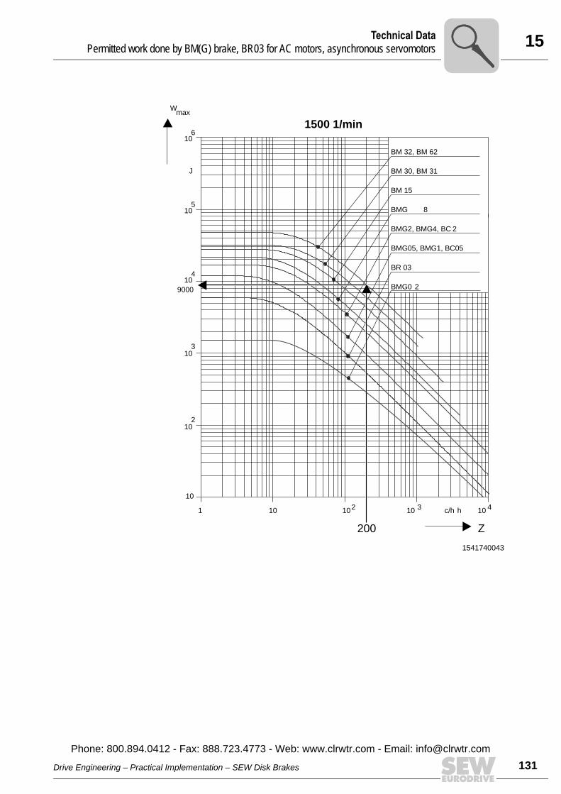
15Technical DataPermitted work done by BM(G) brake, BR03 for AC motors, asynchronous servomotors
1541740043
1500 1/min
106
105
104
103
102
10
J
Wmax
10101 2 10 3 10 4c/h h
Z
BM 32, BM 62
BM 30, BM 31
BM 15
BMG 8
BMG2, BMG4, BC 2
BMG05, BMG1, BC05
BR 03
BMG0 2
200
9000
Drive Engineering – Practical Implementation – SEW Disk Brakes
Phone: 800.894.0412 - Fax: 888.723.4773 - Web: www.clrwtr.com - Email: info@
131clrwtr.com
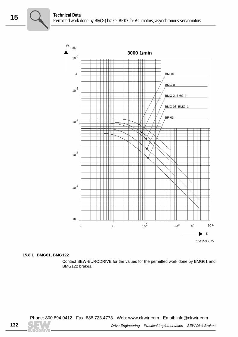
15 echnical Dataermitted work done by BM(G) brake, BR03 for AC motors, asynchronous servomotors
132
15.8.1 BMG61, BMG122Contact SEW-EURODRIVE for the values for the permitted work done by BMG61 andBMG122 brakes.
1542536075
3000 1/min
106
105
104
103
102
10
J
Wmax
102 10101 3 10 4c/h
Z
BM 15
BMG 8
BMG 2, BMG 4
BMG 05, BMG 1
BR 03
TP
Drive Engineering – Practical Implementation – SEW Disk Brakes
Phone: 800.894.0412 - Fax: 888.723.4773 - Web: www.clrwtr.com - Email: [email protected]
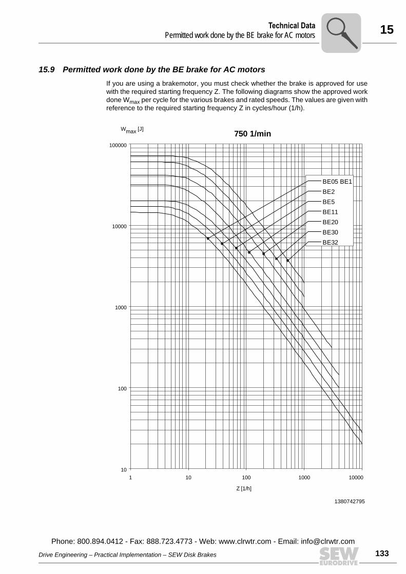
15Technical DataPermitted work done by the BE brake for AC motors
15.9 Permitted work done by the BE brake for AC motorsIf you are using a brakemotor, you must check whether the brake is approved for usewith the required starting frequency Z. The following diagrams show the approved workdone Wmax per cycle for the various brakes and rated speeds. The values are given withreference to the required starting frequency Z in cycles/hour (1/h).
1380742795
750 1/min
Z [1/h]
Wmax [J]
10
100
1000
10000
100000
1 10 100 1000 10000
BE05 BE1
BE2
BE5
BE11
BE20
BE30
BE32
Drive Engineering – Practical Implementation – SEW Disk Brakes
Phone: 800.894.0412 - Fax: 888.723.4773 - Web: www.clrwtr.com - Email: info@
133clrwtr.com
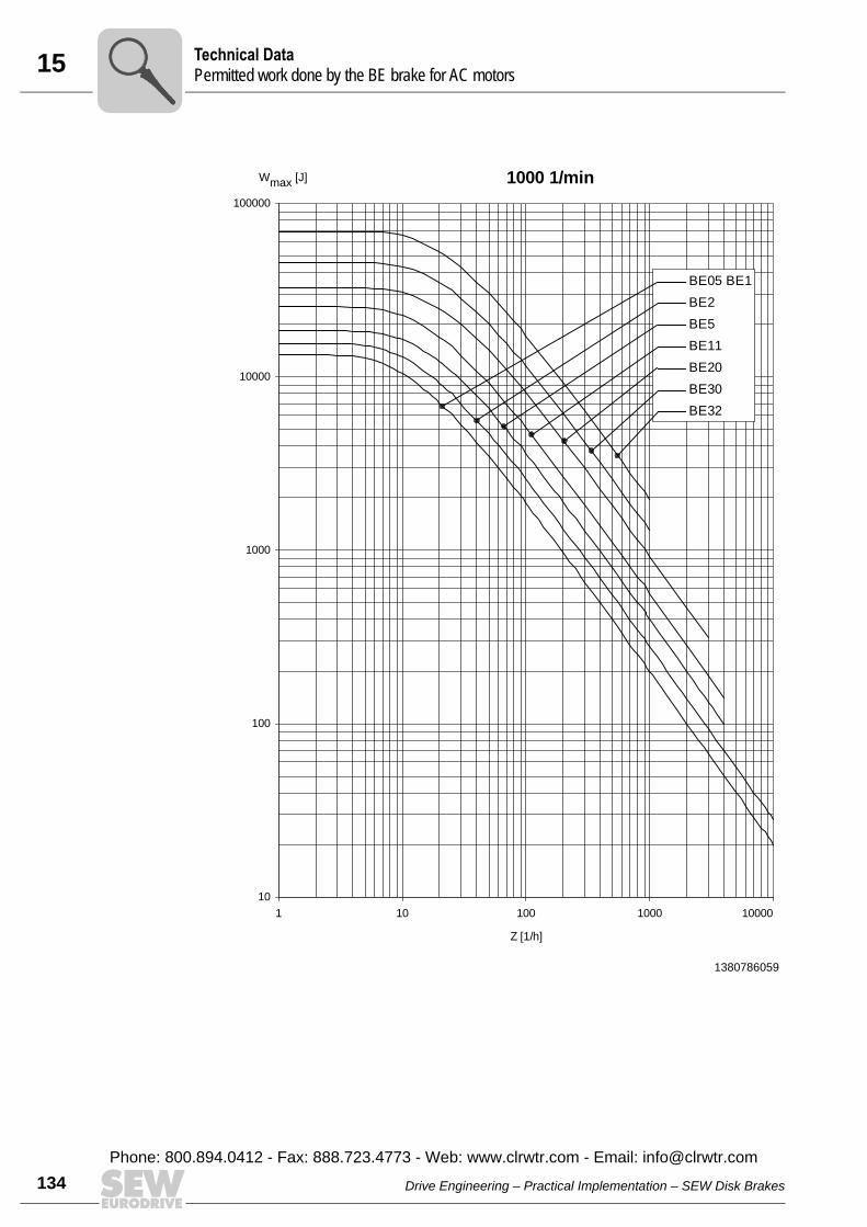
15 echnical Dataermitted work done by the BE brake for AC motors
134
1380786059
10
100
1000
10000
100000
1 10 100 1000 10000
BE05 BE1
BE2
BE5
BE11
BE20
BE30
BE32
1000 1/min
Z [1/h]
Wmax
[J]
TP
Drive Engineering – Practical Implementation – SEW Disk Brakes
Phone: 800.894.0412 - Fax: 888.723.4773 - Web: www.clrwtr.com - Email: [email protected]
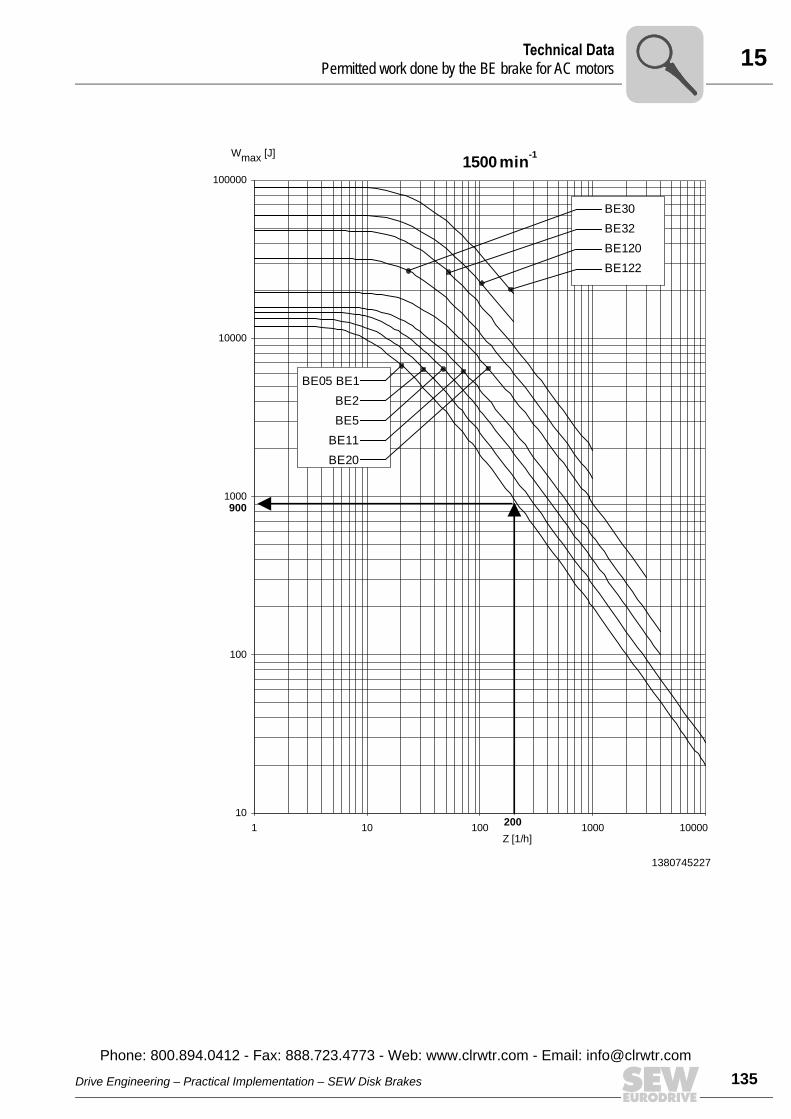
15Technical DataPermitted work done by the BE brake for AC motors
1380745227
Wmax [J]
Z [1/h]
1500
10
100
1000
10000
100000
1 10 100 1000 10000
BE30
BE32
BE120
BE122
min-1
200
900
BE05 BE1
BE2
BE5
BE11
BE20
Drive Engineering – Practical Implementation – SEW Disk Brakes
Phone: 800.894.0412 - Fax: 888.723.4773 - Web: www.clrwtr.com - Email: info@
135clrwtr.com
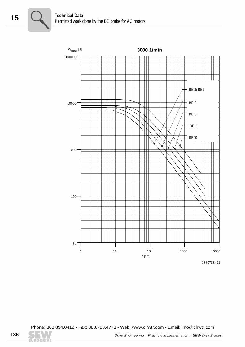
15 echnical Dataermitted work done by the BE brake for AC motors
136
1380788491
3000 1/min
10
100000
1 10
Z [1/h]
Wmax [J]
10000
1000
100
100 1000 10000
BE05 BE1
BE 2
BE 5
BE11
BE20
TP
Drive Engineering – Practical Implementation – SEW Disk Brakes
Phone: 800.894.0412 - Fax: 888.723.4773 - Web: www.clrwtr.com - Email: [email protected]
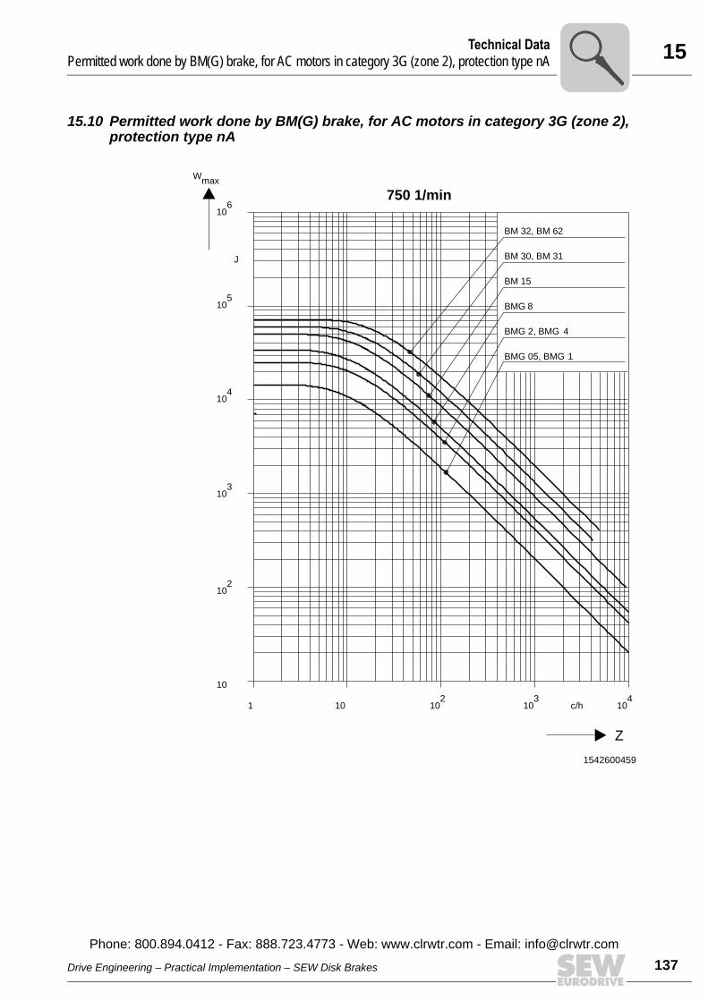
15Technical DataPermitted work done by BM(G) brake, for AC motors in category 3G (zone 2), protection type nA
15.10 Permitted work done by BM(G) brake, for AC motors in category 3G (zone 2), protection type nA
1542600459
Z
BM 32, BM 62
BM 30, BM 31
BM 15
BMG 8
BMG 2, BMG 4
BMG 05, BMG 1
750 1/min
10
102
102
103
c/h 104
101
103
104
105
106
J
Wmax
Drive Engineering – Practical Implementation – SEW Disk Brakes
Phone: 800.894.0412 - Fax: 888.723.4773 - Web: www.clrwtr.com - Email: info@
137clrwtr.com
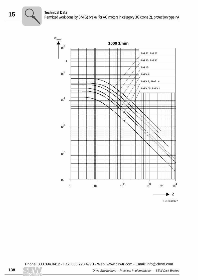
15 echnical Dataermitted work done by BM(G) brake, for AC motors in category 3G (zone 2), protection type nA
138
1542598027
1000 1/min
10
102
102
103
c/h 104
101
103
104
105
106
J
Wmax
Z
BM 32, BM 62
BM 30, BM 31
BM 15
BMG 8
BMG 2, BMG 4
BMG 05, BMG 1
TP
Drive Engineering – Practical Implementation – SEW Disk Brakes
Phone: 800.894.0412 - Fax: 888.723.4773 - Web: www.clrwtr.com - Email: [email protected]
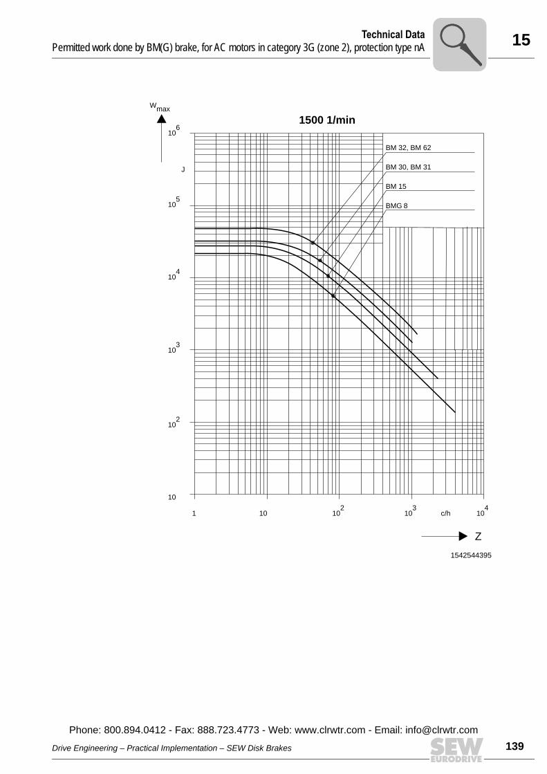
15Technical DataPermitted work done by BM(G) brake, for AC motors in category 3G (zone 2), protection type nA
1542544395
BM 32, BM 62
BM 30, BM 31
BM 15
BMG 8
Z
1500 1/min
10
102
102
103
c/h 104
101
103
104
105
106
J
Wmax
Drive Engineering – Practical Implementation – SEW Disk Brakes
Phone: 800.894.0412 - Fax: 888.723.4773 - Web: www.clrwtr.com - Email: info@
139clrwtr.com
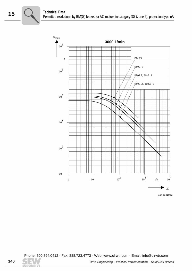
15 echnical Dataermitted work done by BM(G) brake, for AC motors in category 3G (zone 2), protection type nA
140
1542541963
BM 15
BMG 8
BMG 2, BMG 4
BMG 05, BMG 1
3000 1/min
10
102
102
103
c/h 104
101
103
104
105
106
J
Wmax
Z
TP
Drive Engineering – Practical Implementation – SEW Disk Brakes
Phone: 800.894.0412 - Fax: 888.723.4773 - Web: www.clrwtr.com - Email: [email protected]
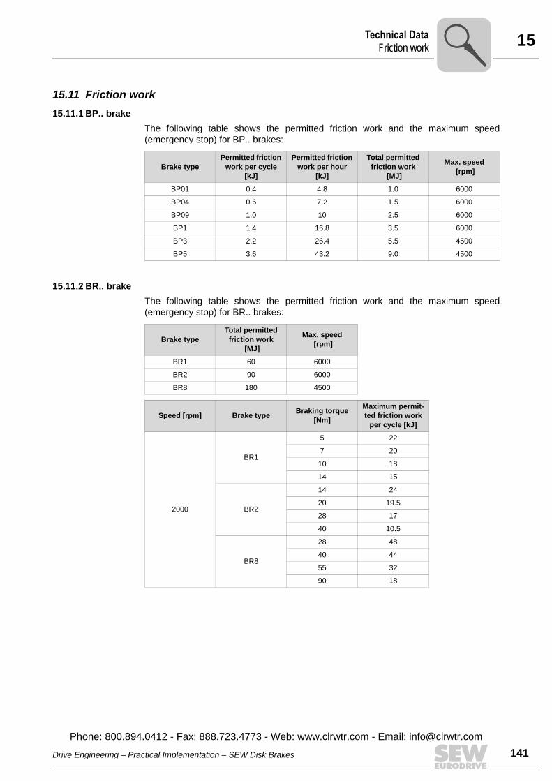
15Technical DataFriction work
15.11 Friction work 15.11.1 BP.. brake
The following table shows the permitted friction work and the maximum speed(emergency stop) for BP.. brakes:
15.11.2 BR.. brakeThe following table shows the permitted friction work and the maximum speed(emergency stop) for BR.. brakes:
Brake typePermitted friction
work per cycle [kJ]
Permitted friction work per hour
[kJ]
Total permitted friction work
[MJ]
Max. speed [rpm]
BP01 0.4 4.8 1.0 6000
BP04 0.6 7.2 1.5 6000
BP09 1.0 10 2.5 6000
BP1 1.4 16.8 3.5 6000
BP3 2.2 26.4 5.5 4500
BP5 3.6 43.2 9.0 4500
Brake typeTotal permitted
friction work [MJ]
Max. speed [rpm]
BR1 60 6000
BR2 90 6000
BR8 180 4500
Speed [rpm] Brake type Braking torque [Nm]
Maximum permit-ted friction work
per cycle [kJ]
2000
BR1
5 22
7 20
10 18
14 15
BR2
14 24
20 19.5
28 17
40 10.5
BR8
28 48
40 44
55 32
90 18
Drive Engineering – Practical Implementation – SEW Disk Brakes
Phone: 800.894.0412 - Fax: 888.723.4773 - Web: www.clrwtr.com - Email: info@
141clrwtr.com
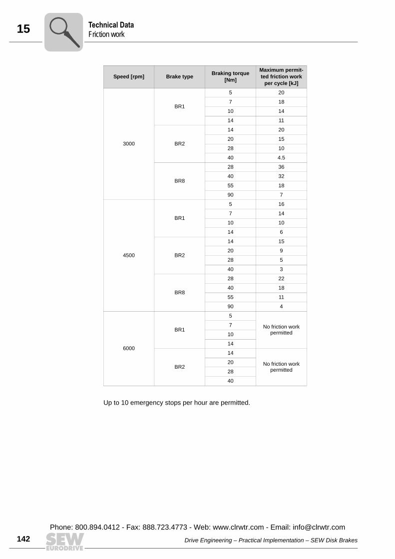
15 echnical Datariction work
142
Up to 10 emergency stops per hour are permitted.
3000
BR1
5 20
7 18
10 14
14 11
BR2
14 20
20 15
28 10
40 4.5
BR8
28 36
40 32
55 18
90 7
4500
BR1
5 16
7 14
10 10
14 6
BR2
14 15
20 9
28 5
40 3
BR8
28 22
40 18
55 11
90 4
6000
BR1
5
No friction work permitted
7
10
14
BR2
14
No friction work permitted
20
28
40
Speed [rpm] Brake type Braking torque [Nm]
Maximum permit-ted friction work
per cycle [kJ]
TF
Drive Engineering – Practical Implementation – SEW Disk Brakes
Phone: 800.894.0412 - Fax: 888.723.4773 - Web: www.clrwtr.com - Email: [email protected]
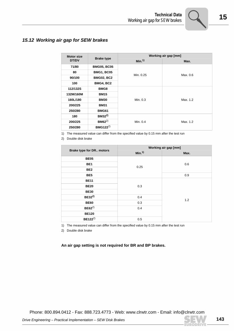
15Technical DataWorking air gap for SEW brakes
15.12 Working air gap for SEW brakes
An air gap setting is not required for BR and BP brakes.
Motor size DT/DV Brake type
Working air gap [mm]
Min.1)
1) The measured value can differ from the specified value by 0.15 mm after the test run
Max.
71/80 BMG05, BC05
Min. 0.25 Max. 0.680 BMG1, BC05
90/100 BMG02, BC2
100 BMG4, BC2
112/132S BMG8
Min. 0.3 Max. 1.2
132M/160M BM15
160L/180 BM30
200/225 BM31
250/280 BMG61
180 BM322)
2) Double disk brake
Min. 0.4 Max. 1.2200/225 BM622)
250/280 BMG1222)
Brake type for DR.. motorsWorking air gap [mm]
Min.1)
1) The measured value can differ from the specified value by 0.15 mm after the test run
Max.
BE05
0.250.6BE1
BE2
BE5 0.9
BE11
0.3
1.2
BE20
BE30
BE322)
2) Double disk brake
0.4
BE60 0.3
BE622) 0.4
BE120
BE1222) 0.5
Drive Engineering – Practical Implementation – SEW Disk Brakes
Phone: 800.894.0412 - Fax: 888.723.4773 - Web: www.clrwtr.com - Email: info@
143clrwtr.com
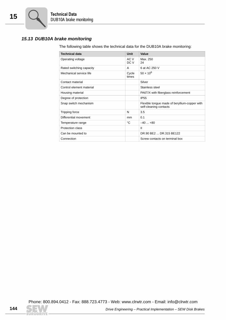
15 echnical DataUB10A brake monitoring
144
15.13 DUB10A brake monitoringThe following table shows the technical data for the DUB10A brake monitoring:
Technical data Unit Value
Operating voltage AC VDC V
Max. 25024
Rated switching capacity A 6 at AC 250 V
Mechanical service life Cycle times
50 × 106
Contact material Silver
Control element material Stainless steel
Housing material PA6T/X with fiberglass reinforcement
Degree of protection IP55
Snap switch mechanism Flexible tongue made of beryllium-copper with self-cleaning contacts
Tripping force N 3.5
Differential movement mm 0.1
Temperature range °C –40 ... +80
Protection class II
Can be mounted to DR.90 BE2 ... DR.315 BE122
Connection Screw contacts on terminal box
TD
Drive Engineering – Practical Implementation – SEW Disk Brakes
Phone: 800.894.0412 - Fax: 888.723.4773 - Web: www.clrwtr.com - Email: [email protected]
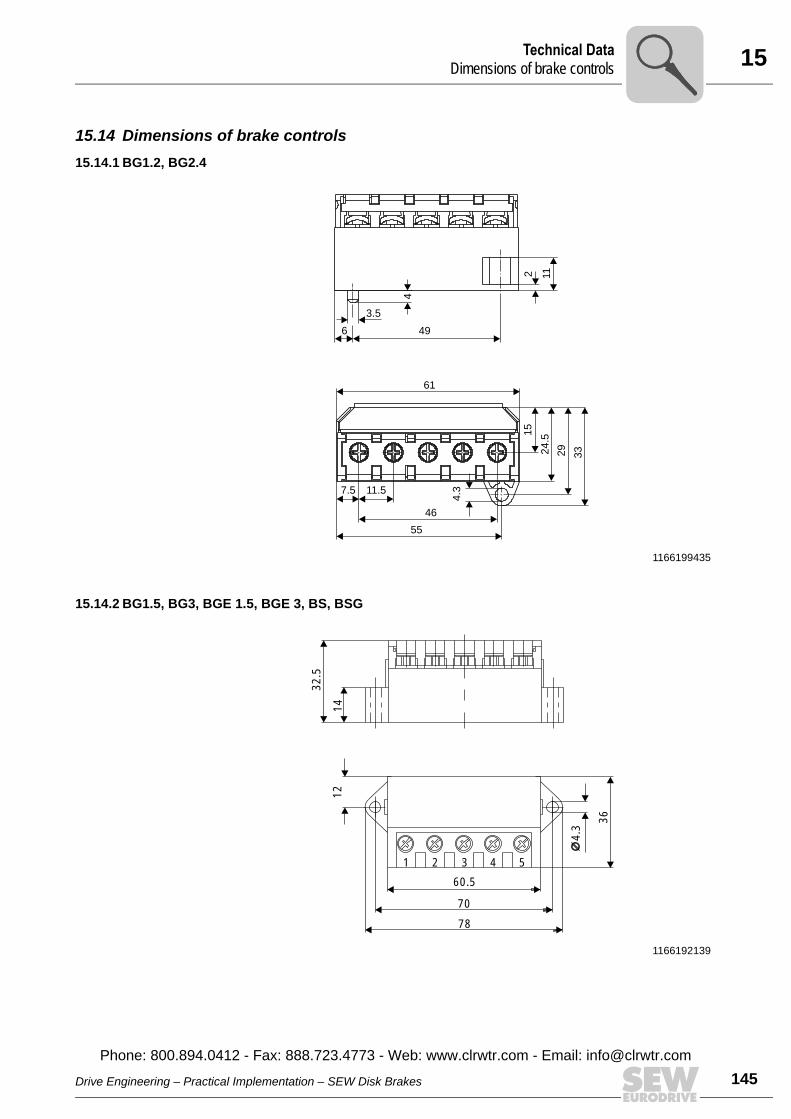
15Technical DataDimensions of brake controls
15.14 Dimensions of brake controls15.14.1 BG1.2, BG2.4
15.14.2 BG1.5, BG3, BGE 1.5, BGE 3, BS, BSG
1166199435
6 493.5
4
112
61
5546
7.5 11.5
1524
.529 33
4.3
1166192139
12
78
70
1 2 3 4 5
36
14
4.3
60.5
32.5
Drive Engineering – Practical Implementation – SEW Disk Brakes
Phone: 800.894.0412 - Fax: 888.723.4773 - Web: www.clrwtr.com - Email: info@
145clrwtr.com
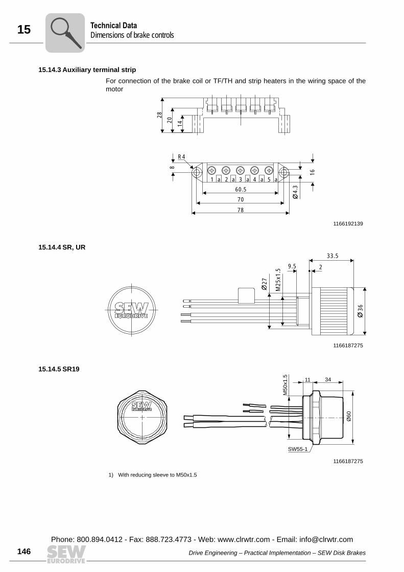
15 echnical Dataimensions of brake controls
146
15.14.3 Auxiliary terminal stripFor connection of the brake coil or TF/TH and strip heaters in the wiring space of themotor
15.14.4 SR, UR
15.14.5 SR19
1166192139
28
20
148
R4
70
78
16
1 a 2 a 3 a 4 a 5 a
60.5 4.3
1166187275
227
M25
x1.5
36
33.5
9.5
1166187275
1) With reducing sleeve to M50x1.5
Ø60
34
SW55-1
11
M50x1.5
TD
Drive Engineering – Practical Implementation – SEW Disk Brakes
Phone: 800.894.0412 - Fax: 888.723.4773 - Web: www.clrwtr.com - Email: [email protected]
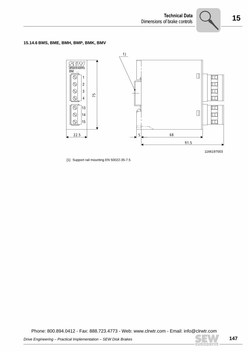
15Technical DataDimensions of brake controls
15.14.6 BMS, BME, BMH, BMP, BMK, BMV
1166197003
[1] Support rail mounting EN 50022-35-7.5
15
14
13
4
3
2
1
BM. ...
75
5 68
1)
22.5
91.5
Drive Engineering – Practical Implementation – SEW Disk Brakes
Phone: 800.894.0412 - Fax: 888.723.4773 - Web: www.clrwtr.com - Email: info@
147clrwtr.com
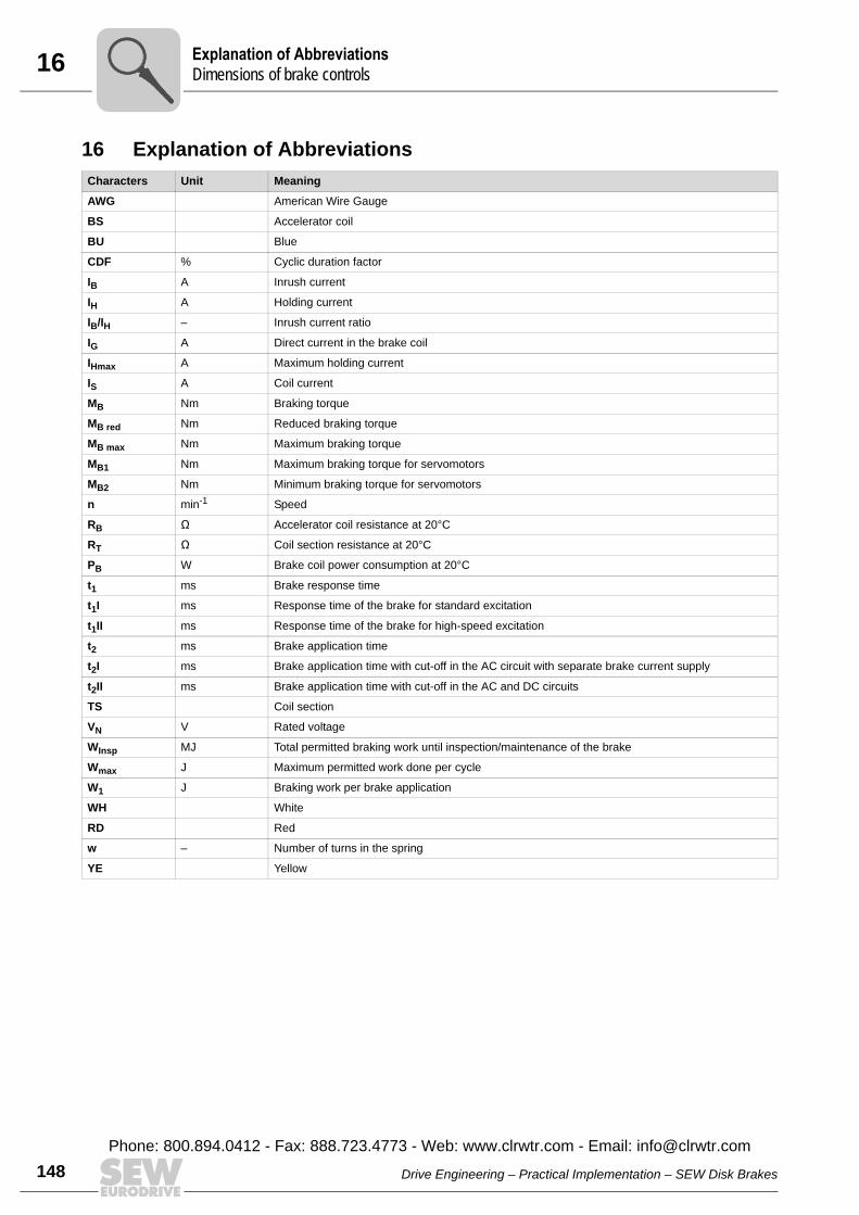
16 xplanation of Abbreviationsimensions of brake controls
148
16 Explanation of AbbreviationsCharacters Unit Meaning
AWG American Wire Gauge
BS Accelerator coil
BU Blue
CDF % Cyclic duration factor
IB A Inrush current
IH A Holding current
IB/IH – Inrush current ratio
IG A Direct current in the brake coil
IHmax A Maximum holding current
IS A Coil current
MB Nm Braking torque
MB red Nm Reduced braking torque
MB max Nm Maximum braking torque
MB1 Nm Maximum braking torque for servomotors
MB2 Nm Minimum braking torque for servomotors
n min-1 Speed
RB Ê Accelerator coil resistance at 20°C
RT Ê Coil section resistance at 20°C
PB W Brake coil power consumption at 20°C
t1 ms Brake response time
t1I ms Response time of the brake for standard excitation
t1II ms Response time of the brake for high-speed excitation
t2 ms Brake application time
t2I ms Brake application time with cut-off in the AC circuit with separate brake current supply
t2II ms Brake application time with cut-off in the AC and DC circuits
TS Coil section
VN V Rated voltage
WInsp MJ Total permitted braking work until inspection/maintenance of the brake
Wmax J Maximum permitted work done per cycle
W1 J Braking work per brake application
WH White
RD Red
w – Number of turns in the spring
YE Yellow
ED
Drive Engineering – Practical Implementation – SEW Disk Brakes
Phone: 800.894.0412 - Fax: 888.723.4773 - Web: www.clrwtr.com - Email: [email protected]
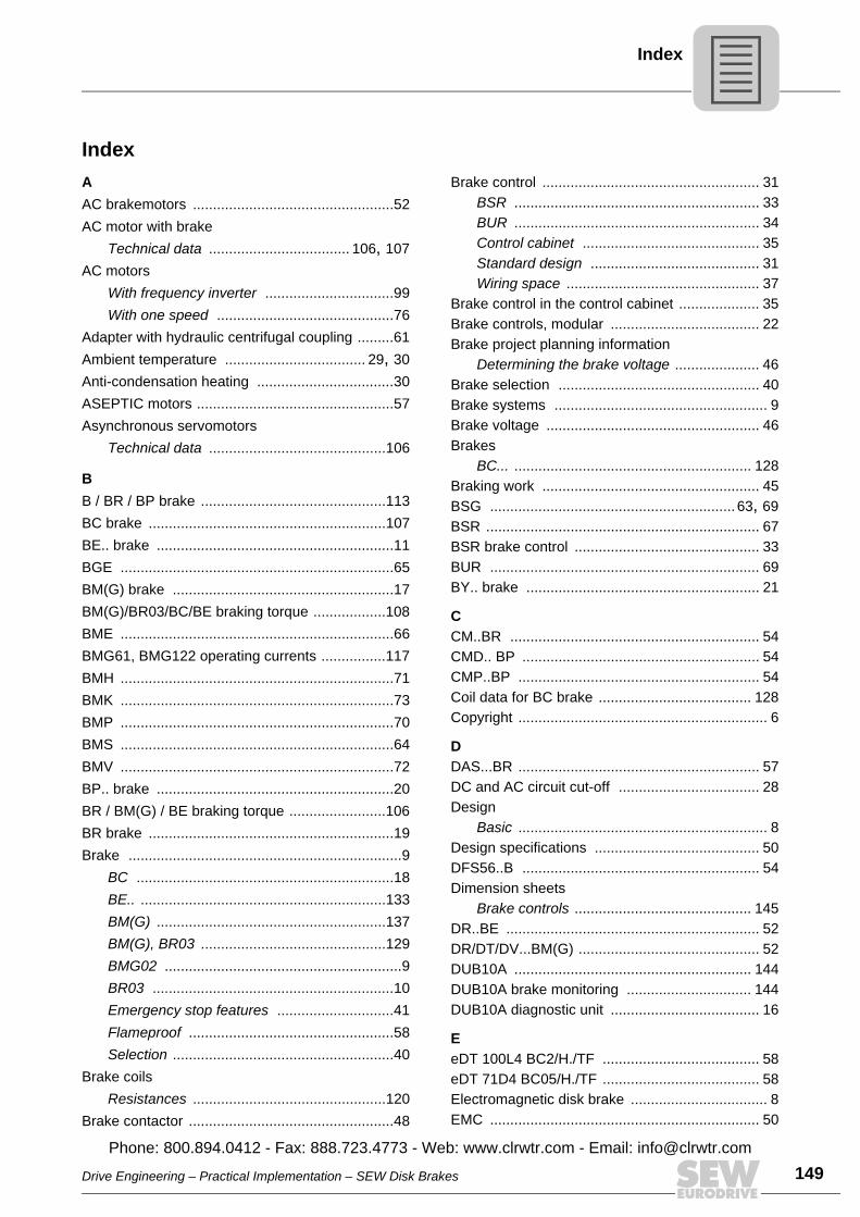
Index
IndexAAC brakemotors ..................................................52AC motor with brake
Technical data ................................... 106, 107AC motors
With frequency inverter ................................99With one speed ............................................76
Adapter with hydraulic centrifugal coupling .........61Ambient temperature ................................... 29, 30Anti-condensation heating ..................................30ASEPTIC motors .................................................57Asynchronous servomotors
Technical data ............................................106
BB / BR / BP brake ..............................................113BC brake ...........................................................107BE.. brake ...........................................................11BGE ....................................................................65BM(G) brake .......................................................17BM(G)/BR03/BC/BE braking torque ..................108BME ....................................................................66BMG61, BMG122 operating currents ................117BMH ....................................................................71BMK ....................................................................73BMP ....................................................................70BMS ....................................................................64BMV ....................................................................72BP.. brake ...........................................................20BR / BM(G) / BE braking torque ........................106BR brake .............................................................19Brake ....................................................................9
BC ................................................................18BE.. .............................................................133BM(G) .........................................................137BM(G), BR03 ..............................................129BMG02 ...........................................................9BR03 ............................................................10Emergency stop features .............................41Flameproof ...................................................58Selection .......................................................40
Brake coilsResistances ................................................120
Brake contactor ...................................................48
Brake control ...................................................... 31BSR ............................................................. 33BUR ............................................................. 34Control cabinet ............................................ 35Standard design .......................................... 31Wiring space ................................................ 37
Brake control in the control cabinet .................... 35Brake controls, modular ..................................... 22Brake project planning information
Determining the brake voltage ..................... 46Brake selection .................................................. 40Brake systems ..................................................... 9Brake voltage ..................................................... 46Brakes
BC... ........................................................... 128Braking work ...................................................... 45BSG ............................................................. 63, 69BSR .................................................................... 67BSR brake control .............................................. 33BUR ................................................................... 69BY.. brake .......................................................... 21
CCM..BR .............................................................. 54CMD.. BP ........................................................... 54CMP..BP ............................................................ 54Coil data for BC brake ...................................... 128Copyright .............................................................. 6
DDAS...BR ............................................................ 57DC and AC circuit cut-off ................................... 28Design
Basic .............................................................. 8Design specifications ......................................... 50DFS56..B ........................................................... 54Dimension sheets
Brake controls ............................................ 145DR..BE ............................................................... 52DR/DT/DV...BM(G) ............................................. 52DUB10A ........................................................... 144DUB10A brake monitoring ............................... 144DUB10A diagnostic unit ..................................... 16
EeDT 100L4 BC2/H./TF ....................................... 58eDT 71D4 BC05/H./TF ....................................... 58Electromagnetic disk brake .................................. 8EMC ................................................................... 50
Drive Engineering – Practical Implementation – SEW Disk Brakes
Phone: 800.894.0412 - Fax: 888.723.4773 - Web: www.clrwtr.com - Email: info@
149clrwtr.com
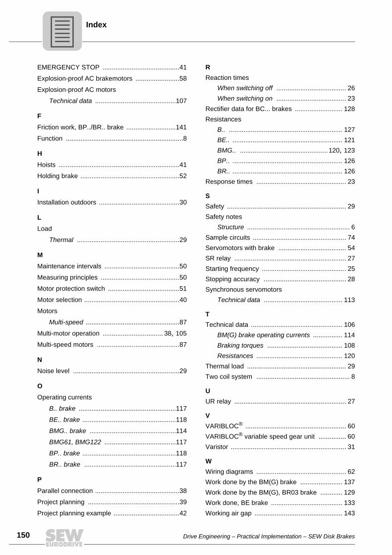
150
dex
EMERGENCY STOP ..........................................41Explosion-proof AC brakemotors ........................58Explosion-proof AC motors
Technical data ............................................107
FFriction work, BP../BR.. brake ...........................141Function ................................................................8
HHoists ..................................................................41Holding brake ......................................................52
IInstallation outdoors ............................................30
LLoad
Thermal ........................................................29
MMaintenance intervals .........................................50Measuring principles ...........................................50Motor protection switch .......................................51Motor selection ....................................................40Motors
Multi-speed ...................................................87Multi-motor operation ................................. 38, 105Multi-speed motors .............................................87
NNoise level ..........................................................29
OOperating currents
B.. brake .....................................................117BE.. brake ...................................................118BMG.. brake ...............................................114BMG61, BMG122 .......................................117BP.. brake ...................................................118BR.. brake ..................................................117
PParallel connection ..............................................38Project planning ..................................................39Project planning example ....................................42
RReaction times
When switching off ...................................... 26When switching on ...................................... 23
Rectifier data for BC... brakes .......................... 128Resistances
B.. .............................................................. 127BE.. ............................................................ 121BMG.. ................................................ 120, 123BP.. ............................................................ 126BR.. ............................................................ 126
Response times ................................................. 23
SSafety ................................................................. 29Safety notes
Structure ........................................................ 6Sample circuits ................................................... 74Servomotors with brake ..................................... 54SR relay ............................................................. 27Starting frequency .............................................. 25Stopping accuracy ............................................. 28Synchronous servomotors
Technical data ........................................... 113
TTechnical data .................................................. 106
BM(G) brake operating currents ................ 114Braking torques ......................................... 108Resistances ............................................... 120
Thermal load ...................................................... 29Two coil system ................................................... 8
UUR relay ............................................................. 27
VVARIBLOC® ....................................................... 60VARIBLOC® variable speed gear unit ............... 60Varistor ............................................................... 31
WWiring diagrams ................................................. 62Work done by the BM(G) brake ....................... 137Work done by the BM(G), BR03 brake ............ 129Work done, BE brake ....................................... 133Working air gap ................................................ 143
In
Drive Engineering – Practical Implementation – SEW Disk Brakes