connect the umc100.3 to an allen-bradley plc over ethernet
TRANSCRIPT

APPLICATION NOTE
2CD
C13
5060
M02
01
Rev
. A (0
3/20
18)
Connect the UMC100.3 to an Allen-Bradley PLC over EtherNet/IP™ using the EIU32.0 Universal Motor Controller UMC100.3 and EtherNet/IP™
In this application note will be described how the ABB Universal Motor Controller UMC100.3, equipped with an EIU32.0 EtherNet/IP™ communication interface, can be connected to an Allen-Bradley CompactLogix PLC.
This document is made for technicians integrating the UMC100.3 into an Allen-Bradley PLC.
A qualified knowledge of EtherNet/IP™, CompactLogix and Studio 5000 is required and expected. The basics are not part of this document.
Application Note │ Connect the UMC100.3 to an Allen-Bradley PLC over EtherNet/IP™ using the EIU32.0 2
EDS file
For integrating the UMC100.3 into the PLC, the EDS file has to be downloaded and installed.
The latest EDS file can be downloaded from our website:
www.abb.com
Products Low Voltage Products and Systems Automation, control and protection Motor controllers Universal Motor Controllers Ethernet Interfaces
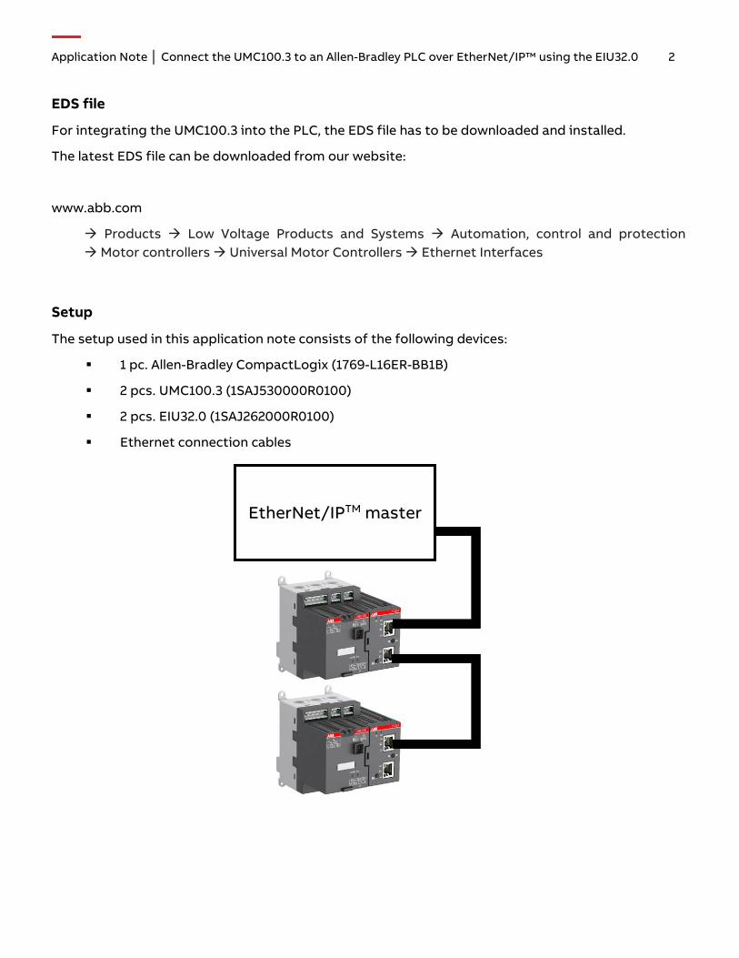
Setup
The setup used in this application note consists of the following devices:
1 pc. Allen-Bradley CompactLogix (1769-L16ER-BB1B)
2 pcs. UMC100.3 (1SAJ530000R0100)
2 pcs. EIU32.0 (1SAJ262000R0100)
Ethernet connection cables
EtherNet/IPTM master

Application Note │ Connect the UMC100.3 to an Allen-Bradley PLC over EtherNet/IP™ using the EIU32.0 3
EIU32.0 configuration
To enable communication through the EtherNet/IP™ network, the EIU32.0 needs a valid IP-address.
There are three different ways for setting an IP-address via the connected UMC:
1. DHCP: In this mode the EIU32.0 will get its IP-address from a DHCP server inside the network
2. Basic: With the Basic setting, the first three octets are fixed to 192.162.1.xxx. The last octet willbe automatically set as FBP-address of the UMC100.3
3. User-defined: With this setting all four octets can be set directly from the user.
The configuration of the EIU32.0 can be done over the connected UMC, using the operator panel UMC100-PAN:
Enter the Menu Communication Ethernet and set the following parameters:
Parameter Name Default Setting Allowed Range
IP Setting Mode DHCP DHCP / Basic / User defined
IP address octet 1 192 0 – 255
IP address octet 2 168 0 – 255
IP address octet 3 1 0 – 255
IP address octet 4 UMC address 0 – 255
Subnet mask octet 1 255 0 – 255
Subnet mask octet 2 255 0 – 255
Subnet mask octet 3 255 0 – 255
Subnet mask octet 4 0 0 – 255
Gateway octet 1 0 0 – 255
Gateway octet 2 0 0 – 255
Gateway octet 3 0 0 – 255
Gateway octet 4 0 0 – 255
Enable webserver Off On / Off
When the IP setting mode is set to “Basic”, you’ll be able to change also octets 1 – 3 of the IP-address. This setting will be ignored and set back to the above mentioned default values!

Application Note │ Connect the UMC100.3 to an Allen-Bradley PLC over EtherNet/IP™ using the EIU32.0 4
Adding the EIU32.0 to the Project
After creating a project in Studio 5000 and installing the EIU32.0 EDS file, the devices will be added to the project tree:
1. Expand “I/O configuration”, right-click on “Ethernet” and select “New Module”
2. Select the “EIU32.0” from the catalog and click on “Create”
3. Insert the name and IP-address and click on “Change”
4. Insert a connection, in this case “Excl. Owner I/O +Diag, Config.” and click on “OK”
5. Repeat steps 1 to 4 for all UMC100.3

Application Note │ Connect the UMC100.3 to an Allen-Bradley PLC over EtherNet/IP™ using the EIU32.0 5
UMC100.3 Configuration with Parameters
Besides the possibility to use the DTM or UMC100.3 operator panel to parametrize the UMC100.3, the configuration parameters can be used also. The following steps describe where to find the parameters and how to change them. To send the configuration parameters, it is required to select a connection including “Config”.
1. Open “Controller Tags”
2. Expand the EIU32.0 configuration list (name ends with “:C”)
3. Expand the sub list, where the name ends with “:C.Data”.

Application Note │ Connect the UMC100.3 to an Allen-Bradley PLC over EtherNet/IP™ using the EIU32.0 6
All parameters are shown as signed integer. For changing the values, it is easier to change the style from decimal to hexadecimal. A correlation list between the shown values and the UMC100.3 parameters can be found in the appendix of this document.
Using I/O Data to communicate with the UMC100.3
The I/O data of the UMC100.3 contains three different types, the monitoring data, the command data and diagnostic data.
The monitoring data contains in total 16 bytes of data. There are six byte of binary data and five analog words. The telegram is built up as shown in the following screenshot from the UMC100.3 manual:

Application Note │ Connect the UMC100.3 to an Allen-Bradley PLC over EtherNet/IP™ using the EIU32.0 7
To start and stop the motor or to transfer data from the PLC to the UMC100.3, the command telegram can be used. It contains twelve byte data in total and is split into four bytes binary data and four analog words. The following screenshot is taken from the UMC100.3 manual and contains the following content:

Application Note │ Connect the UMC100.3 to an Allen-Bradley PLC over EtherNet/IP™ using the EIU32.0 8
In case the motor stopped due to a fault, there will be available the diagnostic in a separate telegram. This telegram consists of eight bytes. The last byte is a detailed fault code, which is described in detail in the UMC100.3 manual.

Application Note │ Connect the UMC100.3 to an Allen-Bradley PLC over EtherNet/IP™ using the EIU32.0 9
Creating Local Tags
To read data from the UMC100.3 or write commands to the UMC100.3, the global tags can be used or local tags can be created. To create local tags, the following steps have to be fulfilled:
1. Open “Controller Tags” and open the ribbon “Edit Tags”
2. Insert a name for a local tag, e.g. “Mod_1_Mon_Byte_0” (short for Modul 1, Monitoring Byte 0)
3. Expand the related list for “Alias For” and select the corresponding global variable
4. Repeat steps 1 to 3 for each module and all necessary data frames.
The Input data “EIU32_Module_1:I” contains 24 byte data. The first 16 bytes are the monitoring data and the last 8 bytes are reserved for the diagnostic.
The five analog words are stored within two bytes as a high and a low byte.

Application Note │ Connect the UMC100.3 to an Allen-Bradley PLC over EtherNet/IP™ using the EIU32.0 10
Working with Global Tags
After adding the EIU32.0 EtherNet/IP™ module and the connected UMC100.3, the global variables can be directly used within the application. In the following screenshot is shown how digital input 0 of the PLC is sending the remote bit to the UMC100.3 and digital input 1 sends the start command:

Application Note │ Connect the UMC100.3 to an Allen-Bradley PLC over EtherNet/IP™ using the EIU32.0 11
Appendix: Correlation table between PLC parameters and UMC100.3 parameters
Bit Parametername Lower Limit Upper Limit Default Value
Parameter Unit / Selection
C.Data[0] Bit 0-7 Setting Ie1 24 320000 50 0.01A
C.Data[1] Bit 0-7 Setting Ie1
C.Data[2] Bit 0-7 Setting Ie1
C.Data[3] Bit 0-7 Setting Ie1
C.Data[4] Bit 0-7 Setting Ie2 24 320000 50 0.01A
C.Data[5] Bit 0-7 Setting Ie2
C.Data[6] Bit 0-7 Setting Ie2
C.Data[7] Bit 0-7 Setting Ie2
C.Data[8] Bit 0-7 YD Starting Time 10 36000 600 0.1s
C.Data[9] Bit 0-7 YD Starting Time
C.Data[10] Bit 0-7 Current Factor 2 64000 100 %
C.Data[11] Bit 0-7 Current Factor
C.Data[12] Bit 0-7 Cooling Time 30 64000 120 s
C.Data[13] Bit 0-7 Cooling Time
C.Data[14] Bit 0-7 Earth Flt Trip Level 20 255 255 %
C.Data[15] Bit 0-7 Earth Flt Trip Delay 0 255 5 0.1s
C.Data[16] Bit 0-7 Language 0 8 0 0: English: 1: Deutsch: 2: Francais: 3: Espanol: 4: Italiano:
5: Portugues: 6: Russian:
7: Polski: 8: Finnish:
C.Data[17] Bit 0-7 Rev Lock-Out Time 1 255 1 s
C.Data[18] Bit 0-7 Fault Output 0 6 0 0: Off: 1: Flash DO2:
2: On DO2: 3: Invert DO2: 4: Flash DO3:
5: On DO3: 6: Invert DO3:
C.Data[19] Bit 0-7 Trip Class 0 4 1 0: Class 5: 1: Class 10: 2: Class 20: 3: Class 30: 4: Class 40:
C.Data[20] Bit 0-7 Low Curr Warn Level
0 20 10 5%
C.Data[21] Bit 0-7 Low Curr Trip Level 0 20 0 5%
C.Data[22] Bit 0-7 High Curr Warn Level
20 160 30 5%
C.Data[23] Bit 0-7 High Curr Trip Level
20 160 160 5%
C.Data[24] Bit 0-7 Locked Rotor Level 20 160 160 5%

Application Note │ Connect the UMC100.3 to an Allen-Bradley PLC over EtherNet/IP™ using the EIU32.0 12
Bit Parametername Lower Limit Upper Limit Default Value
Parameter Unit / Selection
C.Data[25] Bit 0-7 Locked Rotor Delay
0 255 5 0.1s
C.Data[26] Bit 0-7 Custom App Parameter
0 255 0
C.Data[27] Bit 0-7 Multif In 0 0 20 0 0: Off: 1: Stop (NC): 2: Stop (NO):
3: Ext. Flt (NC) always: 4: Ext. Flt (NO) always:
5: Ext. Flt (NC) Motor on: 6: Ext. Flt (NO) Motor on:
7: Prep. emerg. Start (NC): 8: Prep. emerg. Start (NO):
9: Testposition (NC): 10: Testposition (NO):
11: Force local (NC): 12: Force local (NO): 13: Fault reset (NC): 14: Fault reset (NO):
15: Voltage DIP (NC): 16: Voltage DIP (NO):
17: CEM11 always (Warning): 18: CEM11 after startup (Warning):
19: CEM11 always (Fault): 20: CEM11 after startup time (Fault):
C.Data[28] Bit 0-7 Multif In 1 0 20 0 0: Off: 1: Stop (NC): 2: Stop (NO):
3: Ext. Flt (NC) always: 4: Ext. Flt (NO) always:
5: Ext. Flt (NC) Motor on: 6: Ext. Flt (NO) Motor on:
7: Prep. emerg. Start (NC): 8: Prep. emerg. Start (NO):
9: Testposition (NC): 10: Testposition (NO):
11: Force local (NC): 12: Force local (NO): 13: Fault reset (NC): 14: Fault reset (NO):
15: Voltage DIP (NC): 16: Voltage DIP (NO):
17: CEM11 always (Warning): 18: CEM11 after startup (Warning):
19: CEM11 always (Fault): 20: CEM11 after startup time (Fault):
C.Data[29] Bit 0-7 Multif In 2 0 20 0 0: Off: 1: Stop (NC): 2: Stop (NO):
3: Ext. Flt (NC) always: 4: Ext. Flt (NO) always:
5: Ext. Flt (NC) Motor on: 6: Ext. Flt (NO) Motor on:
7: Prep. emerg. Start (NC): 8: Prep. emerg. Start (NO):
9: Testposition (NC): 10: Testposition (NO):
11: Force local (NC): 12: Force local (NO):

Application Note │ Connect the UMC100.3 to an Allen-Bradley PLC over EtherNet/IP™ using the EIU32.0 13
Bit Parametername Lower Limit Upper Limit Default Value
Parameter Unit / Selection
13: Fault reset (NC): 14: Fault reset (NO):
15: Voltage DIP (NC): 16: Voltage DIP (NO):
17: CEM11 always (Warning): 18: CEM11 after startup (Warning):
19: CEM11 always (Fault): 20: CEM11 after startup time (Fault):
C.Data[30] Bit 0-7 Multif In 0 Delay 0 255 0 0.1s
C.Data[31] Bit 0-7 Multif In 1 Delay 0 255 0 0.1s
C.Data[32] Bit 0-7 Multif In 2 Delay 0 255 0 0.1s
C.Data[33] Control Function 1 13 3 1: Transparent: 2: Overload Relay:
3: Direct Starter: 4: Reverse Starter:
5: Star-delta Starter: 7: Pole-Changing Starter:
9: Actuator 1: 10: Actuator 2: 11: Actuator 3: 12: Actuator 4:
13: Softstarter:
C.Data[34] Bit 0-3 Busfault Reaction 0 3 0 0: Motor Off: 1: Retain:
2: Start Forward: 3: Start Reverse:
C.Data[34] Bit 4-7 Reserved 0 1 0
C.Data[35] Bit 0-3 Aux Inp 1 Reaction 0 8 0 0: Disabled: 1: Fault (NC) Motor in On/Off: 2: Fault (NO) Motor in On/Off:
3: Fault (NC) Motor in On: 4: Fault (NO) Motor in On:
5: Warning (NC) Motor in On/Off: 6: Warning (NO) Motor in On/Off:
7: Warning (NC) Motor in On: 8: Warning (NO) Motor in On:
C.Data[35] Bit 4-7 Aux Inp 2 Reaction 0 8 0 0: Disabled: 1: Fault (NC) Motor in On/Off: 2: Fault (NO) Motor in On/Off:
3: Fault (NC) Motor in On: 4: Fault (NO) Motor in On:
5: Warning (NC) Motor in On/Off: 6: Warning (NO) Motor in On/Off:
7: Warning (NC) Motor in On: 8: Warning (NO) Motor in On:
C.Data[36] Bit 0-3 Aux Inp 3 Reaction 0 8 0 0: Disabled: 1: Fault (NC) Motor in On/Off: 2: Fault (NO) Motor in On/Off:
3: Fault (NC) Motor in On: 4: Fault (NO) Motor in On:
5: Warning (NC) Motor in On/Off: 6: Warning (NO) Motor in On/Off:
7: Warning (NC) Motor in On: 8: Warning (NO) Motor in On:

Application Note │ Connect the UMC100.3 to an Allen-Bradley PLC over EtherNet/IP™ using the EIU32.0 14
Bit Parametername Lower Limit Upper Limit Default Value
Parameter Unit / Selection
C.Data[36] Bit 4-7 Aux Inp 4 Reaction 0 8 0 0: Disabled: 1: Fault (NC) Motor in On/Off: 2: Fault (NO) Motor in On/Off:
3: Fault (NC) Motor in On: 4: Fault (NO) Motor in On:
5: Warning (NC) Motor in On/Off: 6: Warning (NO) Motor in On/Off:
7: Warning (NC) Motor in On: 8: Warning (NO) Motor in On:
C.Data[37] Bit 0-3 Aux Inp 5 Reaction 0 8 0 0: Disabled: 1: Fault (NC) Motor in On/Off: 2: Fault (NO) Motor in On/Off:
3: Fault (NC) Motor in On: 4: Fault (NO) Motor in On:
5: Warning (NC) Motor in On/Off: 6: Warning (NO) Motor in On/Off:
7: Warning (NC) Motor in On: 8: Warning (NO) Motor in On:
C.Data[37] Bit 4-7 Aux Inp 6 Reaction 0 8 0 0: Disabled: 1: Fault (NC) Motor in On/Off: 2: Fault (NO) Motor in On/Off:
3: Fault (NC) Motor in On: 4: Fault (NO) Motor in On:
5: Warning (NC) Motor in On/Off: 6: Warning (NO) Motor in On/Off:
7: Warning (NC) Motor in On: 8: Warning (NO) Motor in On:
C.Data[38] Bit 0-1 PTC, Thermistor 0 2 0 0: Disabled: 1: Trip:
2: Warning:
C.Data[38] Bit 2-3 Check-Back 1 3 2 1: Contact DI0: 2: Current:
3: Simulation:
C.Data[38] Bit 4-5 Check Phase Sequence
0 2 0 0: Disabled: 1: Trip:
2: Warning:
C.Data[38] Bit 6-7 Reserved 0 1 0
C.Data[39] Bit 0 Fault Auto Reset 0 1 0 0: Off: 1: On:
C.Data[39] Bit 1 Emergency Start 0 1 0 0: Off: 1: On:
C.Data[39] Bit 2 Earth Flt Detection 0 1 1 0: Always: 1: After Startup:
C.Data[39] Bit 3 Address Check 0 1 0 0: Off: 1: On:
C.Data[39] Bit 4 Enable Custom Logic
0 1 0 0: No:1: Yes:
C.Data[39] Bit 5 YD Change-Over Mode
0 1 1 0: Time: 1: Current:
C.Data[39] Bit 6 Phase Loss Prot. 0 1 1 0: Off: 1: On:
C.Data[39] Bit 7 Resistive Load 0 1 0 0: No: 1: Yes:
C.Data[40] Bit 0 DX1xx Enabled 0 1 0 0: Off: 1: On:
C.Data[40] Bit 1 AI1xx AM1 Enabled 0 1 0 0: Off: 1: On:
C.Data[40] Bit 2 AI1xx AM2 Enabled 0 1 0 0: Off: 1: On:
C.Data[40] Bit 3 VI15x Enabled 0 1 0 0: Off: 1: On:

Application Note │ Connect the UMC100.3 to an Allen-Bradley PLC over EtherNet/IP™ using the EIU32.0 15
Bit Parametername Lower Limit Upper Limit Default Value
Parameter Unit / Selection
C.Data[40] Bit 4 – 6 Reserved
C.Data[40] Bit 7 Missing Module React.
0 1 0 0: Error: 1: Warning:
C.Data[41] Bit 0 Aux Inp 1 Ack Mode 0 1 0 0: Manual Reset: 1: Auto Reset:
C.Data[41] Bit 1 Aux Inp 2 Ack Mode 0 1 0 0: Manual Reset: 1: Auto Reset:
C.Data[41] Bit 2 Aux Inp 3 Ack Mode
0 1 0 0: Manual Reset: 1: Auto Reset:
C.Data[41] Bit 3 Aux Inp 4 Ack Mode
0 1 0 0: Manual Reset: 1: Auto Reset:
C.Data[41] Bit 4 Aux Inp 5 Ack Mode
0 1 0 0: Manual Reset: 1: Auto Reset:
C.Data[41] Bit 5 Aux Inp 6 Ack Mode
0 1 0 0: Manual Reset: 1: Auto Reset:
C.Data[41] Bit 6 Number Of Phases 0 1 0 0: 3 Phases: 1: 1 Phase:
C.Data[41] Bit 7 Cooling Mode 0 1 0 0: Time: 1: x% Therm. Load:
C.Data[42] Bit 0 Invert DI Start Inp. 0 1 0 0: No: 1: Yes:
C.Data[42] Bit 1 Invert DI Stop Inp. 0 1 1 0: No: 1: Yes:
C.Data[42] Bit 2 - 3 Reserved
C.Data[42] Bit 4 Inching DI Start Inp 0 1 0 0: No: 1: Yes:
C.Data[42] Bit 5 - 7 Reserved
C.Data[43] Bit 0 Loc 1 Start Bus Cyc 0 1 0 0: No: 1: Yes:
C.Data[43] Bit 1 Loc 1 Stop Bus Cyc 0 1 1 0: No: 1: Yes:
C.Data[43] Bit 2 Loc 1 Start DI 0 1 1 0: No: 1: Yes:
C.Data[43] Bit 3 Loc 1 Stop DI 0 1 1 0: No: 1: Yes:
C.Data[43] Bit 4 Loc 1 Start LCD 0 1 1 0: No: 1: Yes:
C.Data[43] Bit 5 Loc 1 Stop LCD 0 1 1 0: No: 1: Yes:
C.Data[43] Bit 6 Loc 1 Start Bus Acyc
0 1 0 0: No: 1: Yes:
C.Data[43] Bit 7 Loc 1 Stop Bus Acyc
0 1 1 0: No: 1: Yes:
C.Data[44] Bit 0 Auto Start Bus Cyc 0 1 1 0: No: 1: Yes:
C.Data[44] Bit 1 Auto Stop Bus Cyc 0 1 1 0: No: 1: Yes:
C.Data[44] Bit 2 Auto Start DI 0 1 0 0: No: 1: Yes:
C.Data[44] Bit 3 Auto Stop DI 0 1 1 0: No: 1: Yes:
C.Data[44] Bit 4 Auto Start LCD 0 1 0 0: No: 1: Yes:
C.Data[44] Bit 5 Auto Stop LCD 0 1 1 0: No: 1: Yes:
C.Data[44] Bit 6 Auto Start Bus Acyc
0 1 1 0: No: 1: Yes:
C.Data[44] Bit 7 Auto Stop Bus Acyc
0 1 1 0: No: 1: Yes:

Application Note │ Connect the UMC100.3 to an Allen-Bradley PLC over EtherNet/IP™ using the EIU32.0 16
Bit Parametername Lower Limit Upper Limit Default Value
Parameter Unit / Selection
C.Data[45] Bit 0 Loc 2 Start Bus Cyc 0 1 0 0: No: 1: Yes:
C.Data[45] Bit 1 Loc 2 Stop Bus Cyc 0 1 1 0: No: 1: Yes:
C.Data[45] Bit 2 Loc 2 Start DI 0 1 1 0: No: 1: Yes:
C.Data[45] Bit 3 Loc 2 Stop DI 0 1 1 0: No: 1: Yes:
C.Data[45] Bit 4 Loc 2 Start LCD 0 1 1 0: No: 1: Yes:
C.Data[45] Bit 5 Loc 2 Stop LCD 0 1 1 0: No: 1: Yes:
C.Data[45] Bit 6 Loc 2 Start Bus Acyc
0 1 0 0: No: 1: Yes:
C.Data[45] Bit 7 Loc 2 Stop Bus Acyc
0 1 1 0: No: 1: Yes:
C.Data[46] Bit 0 - 3 Reserved
C.Data[46] Bit 4 Multif In 0 Autoreset
0 1 0 0: No: 1: Yes:
C.Data[46] Bit 5 Multif In 1 Autoreset
0 1 0 0: No: 1: Yes:
C.Data[46] Bit 6 Multif In 2 Autoreset
0 1 0 0: No: 1: Yes:
C.Data[46] Bit 7 Reserved
C.Data[47] Bit 0 - 7 Reserved
C.Data[48] Bit 0 – 7 Reserved
C.Data[49] Bit 0 – 7 Reserved
C.Data[50] Bit 0 – 7 Aux Inp 1 Delay 0 255 0 0.1s
C.Data[51] Bit 0 – 7 Aux Inp 2 Delay 0 255 0 0.1s
C.Data[52] Bit 0 – 7 Aux Inp 3 Delay 0 255 0 0.1s
C.Data[53] Bit 0 – 7 Aux Inp 4 Delay 0 255 0 0.1s
C.Data[54] Bit 0 – 7 Aux Inp 5 Delay 0 255 0 0.1s
C.Data[55] Bit 0 – 7 Aux Inp 6 Delay 0 255 0 0.1s
C.Data[56] Bit 0 – 7 Check-Back Time 1 255 5 0.1s
C.Data[57] Bit 0 – 7 Low Curr Warn Delay
0 255 5 0.1s
C.Data[58] Bit 0 – 7 Low Curr Trip Delay
0 255 5 0.1s
C.Data[59] Bit 0 - 7 High Curr Warn Delay
0 255 5 0.1s
C.Data[60] Bit 0 – 7 High Curr Trip Delay
0 255 5 0.1s
C.Data[61] Bit 0 – 7 Curr Imb Trip Level 0 100 50 %
C.Data[62] Bit 0 – 7 Curr Imb Warn Level
0 100 100 %
C.Data[63] Bit 0 Phase Reversal 0 1 0 0: Phase Sequence L1 L2 L3: 1: Phase Sequence L3 L2 L1:
C.Data[63] Bit 1 – 7 Reserved
C.Data[64] Bit 0 – 7 Restart Level 10 100 30

Application Note │ Connect the UMC100.3 to an Allen-Bradley PLC over EtherNet/IP™ using the EIU32.0 17
Bit Parametername Lower Limit Upper Limit Default Value
Parameter Unit / Selection
C.Data[65] Bit 0 – 7 User Display 1 0 7 0 0: Thermal Load: 1: DX1xx DI:
2: DX1xx DO: 3: Operating Hours: 4: Number of Trips:
5: Number of Starts: 6: max. Startup Current:
7: Real Startup Time:
C.Data[66] Bit 0 – 7 User Display 2 0 7 6 0: Thermal Load: 1: DX1xx DI:
2: DX1xx DO: 3: Operating Hours: 4: Number of Trips:
5: Number of Starts: 6: max. Startup Current:
7: Real Startup Time:
C.Data[67] Bit 0 – 7 User Display 3 0 7 7 0: Thermal Load: 1: DX1xx DI:
2: DX1xx DO: 3: Operating Hours: 4: Number of Trips:
5: Number of Starts: 6: max. Startup Current:
7: Real Startup Time:
C.Data[68] Bit 0 – 7 User Display 4 0 6 4 0: Binary 0: 1: Binary 1:
2: Analog 0: 3: Analog 1:
4: Time to Trip: 5: Time to Cool:
6: Current to earth:
C.Data[69] Bit 0 – 7 User Display 5 0 6 5 0: Binary 0: 1: Binary 1:
2: Analog 0: 3: Analog 1:
4: Time to Trip: 5: Time to Cool:
6: Current to earth:
C.Data[70] Bit 0 - 7 Reserved
C.Data[71] Bit 0 – 7 Dip Duration 1 255 5 0.1s
C.Data[72] Bit 0 – 7 Dip Autorestart Window
1 10 1 0.1s
C.Data[73] Bit 0 – 7 Dip Autorestart Delay
0 255 0 s
C.Data[74] Bit 0 – 7 Thermal Load Warnlev
20 100 100 %
C.Data[75] Bit 0 – 7 Num Starts Allowed
0 32 0
C.Data[76] Bit 0 – 7 Num Starts Window
0 255 0 1 min.
C.Data[77] Bit 0 – 7 Num Starts Pause 0 255 0 1 min.

Application Note │ Connect the UMC100.3 to an Allen-Bradley PLC over EtherNet/IP™ using the EIU32.0 18
Bit Parametername Lower Limit Upper Limit Default Value
Parameter Unit / Selection
C.Data[78] Bit 0 - 7 Earth Flt Warn Level
20 255 255 %
C.Data[79] Bit 0 – 7 Earth Flt Warn Delay
0 255 5 0.1s
C.Data[80] Bit 0 – 7 Dip Restart Level 50 115 90 %
C.Data[81] Bit 0 – 7 Dip Level 50 115 70 %
C.Data[82] Bit 0 – 7 Reserved 0 255 0
C.Data[83] Bit 0 – 7 DX1xx DI Delay 3 200 20 ms
C.Data[84] Bit 0 – 7 AM1 Tmax Delay 0 255 6 s
C.Data[85] Bit 0 – 7 AM2 Tmax Delay 0 255 6 s
C.Data[86] Bit 0 – 1 AM2 CH2 Err Reac 0 2 0 0: Disabled: 1: Trip:
2: Warning:
C.Data[86] Bit 2 – 3 AM2 CH3 Err Reac 0 2 0 0: Disabled: 1: Trip:
2: Warning:
C.Data[86] Bit 4 AM1 Mode 0 1 0 0: Temperature: 1: Universal:
C.Data[86] Bit 5 AM2 Mode 0 1 0 0: Temperature: 1: Universal:
C.Data[86] Bit 6 – 7 Reserved
C.Data[87] Bit 0 - 7 Reserved
C.Data[88] Bit 0 – 7 U Low Trip Level 70 100 70 %
C.Data[89] Bit 0 – 7 U Low Trip Delay 0 255 30 0.1s
C.Data[90] Bit 0 – 7 U Low Warn Level 70 100 70 %
C.Data[91] Bit 0 – 7 U Low Warn Delay 0 255 30 0.1s
C.Data[92] Bit 0 – 7 U High Trip Level 100 116 116 %
C.Data[93] Bit 0 – 7 U High Trip Delay 0 255 30 0.1s
C.Data[94] Bit 0 – 7 U High Warn Level 100 116 116 %
C.Data[95] Bit 0 – 7 U High Warn Delay 0 255 30 0.1s
C.Data[96] Bit 0 – 7 AM1 Tmax Trip Level
0 65535 65535 1K
C.Data[97] Bit 0 – 7 AM1 Tmax Trip Level
C.Data[98] Bit 0 – 7 AM1 Tmax Warn Level
0 65535 65535 1K
C.Data[99] Bit 0 – 7 AM1 Tmax Warn Level
C.Data[100] Bit 0 – 7 AM2 Tmax Trip Level
0 65535 65535 1K
C.Data[101] Bit 0 – 7 AM2 Tmax Trip Level
C.Data[102] Bit 0 – 7 AM2 Tmax Warn Level
0 65535 65535 1K

Application Note │ Connect the UMC100.3 to an Allen-Bradley PLC over EtherNet/IP™ using the EIU32.0 19
Bit Parametername Lower Limit Upper Limit Default Value
Parameter Unit / Selection
C.Data[103] Bit 0 – 7 AM2 Tmax Warn Level
C.Data[104] Bit 0 – 3 AM1 CH1 Type 0 12 0 0: Disabled: 1: PT100 -50 C...+400 C (2-wire): 2: PT100 -50 C...+400 C (3-wire):
3: PT100 -50 C...+70 C (2-wire): 4: PT100 -50 C...+70 C (3-wire):
5: PT1000 -50 C...+400 C (2-wire): 6: PT1000 -50 C...+400 C (3-wire):
7: KTY83 -50 C...+175 C: 8: KTY84 -40 C...+300 C:
9: NTC +80 C...+160 C: 10: 0...10V:
11: 0...20mA: 12: 4...20mA:
C.Data[104] Bit 4 – 7 AM1 CH2 Type 0 12 0 0: Disabled: 1: PT100 -50 C...+400 C (2-wire): 2: PT100 -50 C...+400 C (3-wire):
3: PT100 -50 C...+70 C (2-wire): 4: PT100 -50 C...+70 C (3-wire):
5: PT1000 -50 C...+400 C (2-wire): 6: PT1000 -50 C...+400 C (3-wire):
7: KTY83 -50 C...+175 C: 8: KTY84 -40 C...+300 C:
9: NTC +80 C...+160 C: 10: 0...10V:
11: 0...20mA: 12: 4...20mA:
C.Data[105] Bit 0 – 3 AM1 CH3 Type 0 12 0 0: Disabled: 1: PT100 -50 C...+400 C (2-wire): 2: PT100 -50 C...+400 C (3-wire):
3: PT100 -50 C...+70 C (2-wire): 4: PT100 -50 C...+70 C (3-wire):
5: PT1000 -50 C...+400 C (2-wire): 6: PT1000 -50 C...+400 C (3-wire):
7: KTY83 -50 C...+175 C: 8: KTY84 -40 C...+300 C:
9: NTC +80 C...+160 C: 10: 0...10V:
11: 0...20mA: 12: 4...20mA:
C.Data[105] Bit 4 – 7 AM2 CH1 Type 0 12 0 0: Disabled: 1: PT100 -50 C...+400 C (2-wire): 2: PT100 -50 C...+400 C (3-wire):
3: PT100 -50 C...+70 C (2-wire): 4: PT100 -50 C...+70 C (3-wire):
5: PT1000 -50 C...+400 C (2-wire): 6: PT1000 -50 C...+400 C (3-wire):
7: KTY83 -50 C...+175 C: 8: KTY84 -40 C...+300 C:
9: NTC +80 C...+160 C: 10: 0...10V:
11: 0...20mA: 12: 4...20mA:
C.Data[106] Bit 0 – 3 AM2 CH2 Type 0 12 0 0: Disabled: 1: PT100 -50 C...+400 C (2-wire): 2: PT100 -50 C...+400 C (3-wire):
3: PT100 -50 C...+70 C (2-wire):

Application Note │ Connect the UMC100.3 to an Allen-Bradley PLC over EtherNet/IP™ using the EIU32.0 20
Bit Parametername Lower Limit Upper Limit Default Value
Parameter Unit / Selection
4: PT100 -50 C...+70 C (3-wire): 5: PT1000 -50 C...+400 C (2-wire): 6: PT1000 -50 C...+400 C (3-wire):
7: KTY83 -50 C...+175 C: 8: KTY84 -40 C...+300 C:
9: NTC +80 C...+160 C: 10: 0...10V:
11: 0...20mA: 12: 4...20mA:
C.Data[106] Bit 4 – 7 AM2 CH3 Type 0 12 0 0: Disabled: 1: PT100 -50 C...+400 C (2-wire): 2: PT100 -50 C...+400 C (3-wire):
3: PT100 -50 C...+70 C (2-wire): 4: PT100 -50 C...+70 C (3-wire):
5: PT1000 -50 C...+400 C (2-wire): 6: PT1000 -50 C...+400 C (3-wire):
7: KTY83 -50 C...+175 C: 8: KTY84 -40 C...+300 C:
9: NTC +80 C...+160 C: 10: 0...10V:
11: 0...20mA: 12: 4...20mA:
C.Data[107] Bit 0 – 1 AM1 CH1 Err Reac 0 2 0 0: Disabled: 1: Trip:
2: Warning:
C.Data[107] Bit 2 – 3 AM1 CH2 Err Reac 0 2 0 0: Disabled: 1: Trip:
2: Warning:
C.Data[107] Bit 4 – 5 AM1 CH3 Err Reac 0 2 0 0: Disabled: 1: Trip:
2: Warning:
C.Data[107] Bit 6 – 7 AM2 CH1 Err Reac 0 2 0 0: Disabled: 1: Trip:
2: Warning:
C.Data[108] Bit 0 – 7 Param To PV 1 0 255 1
C.Data[109] Bit 0 – 7 Param To PV 2 0 255 2
C.Data[110] Bit 0 – 7 Param To PV 3 0 255 3
C.Data[111] Bit 0 – 7 Param To PV 4 0 255 4
C.Data[112] Bit 0 – 1 DX1xx AO Type 0 3 0 0: 0-20mA: 1: 4-20mA: 2: 0-10mA:
3: 0-10V:
C.Data[112] Bit 2 – 3 DX1xx AO Err Reac 0 2 0 0: Disabled: 1: Trip:
2 :Warning:
C.Data[112] Bit 4 – 7 Reserved
C.Data[113] Bit 0 – 7 Param To PV 5 0 255 5
C.Data[114] Bit 0 – 7 Mot. op. hours level
0 255 0
C.Data[115] Bit 0 – 7 Mot. stand still lev 0 255 0
C.Data[116] Bit 0 – 1 Reserved

Application Note │ Connect the UMC100.3 to an Allen-Bradley PLC over EtherNet/IP™ using the EIU32.0 21
Bit Parametername Lower Limit Upper Limit Default Value
Parameter Unit / Selection
C.Data[116] Bit 2 – 3 Num Starts Overrun
0 2 0 0: Disabled: 1: Trip:
2: Warning:
C.Data[116] Bit 4 – 5 Num Starts Prewarn
0 2 0 0: Disabled: 1: Trip:
2: Warning:
C.Data[116] Bit 6 – 7 Power Scale Factor 0 3 1 0: Power Scale Factor 1: 1: Power Scale Factor 10:
2: Power Scale Factor 100: 3: Power Scale Factor 1000:
C.Data[117] Bit 0 Backlight 0 1 1 0: Off: 1: On:
C.Data[117] Bit 1 – 2 Password Protection
0 2 0 0: Off: 1: On for Parameters:
2: On for Param. + Motor Control:
C.Data[117] Bit 3 – 4 Dip Enable 0 2 0 0: Off: 1: On:
2: On + Rapid Cycle Lockout:
C.Data[117] Bit 5 Dip Autorestart Enable
0 1 0 0: Off: 1: On:
C.Data[117] Bit 6 LCD Panel T Unit 0 1 0 0: Celcius: 1: Fahrenheit:
C.Data[117] Bit 7 Reserved
C.Data[118] Bit 0 – 7 Nominal Line Voltage
90 690 400 V
C.Data[119] Bit 0 – 7 Nominal Line Voltage
C.Data[120] Bit 0 – 7 PwrFactor Trip Level
30 100 30
C.Data[121] Bit 0 – 7 PwrFactor Trip Delay
0 255 30 0.1s
C.Data[122] Bit 0 – 7 PwrFactor Warn Level
30 100 30
C.Data[123] Bit 0 – 7 PwrFactor Warn Delay
0 255 30 0.1s
C.Data[124] Bit 0 – 7 U Imb. Trip Level 2 200 200 0.1%
C.Data[125] Bit 0 – 7 U Imb. Trip Delay 0 255 10 0.1s
C.Data[126] Bit 0 – 7 U Imb. Warn Level 2 200 200 0.1%
C.Data[127] Bit 0 – 7 U Imb. Warn Delay 0 255 10 0.1s
C.Data[128] Bit 0 – 7 P Low Trip Level 20 100 20 %
C.Data[129] Bit 0 – 7 P Low Trip Delay 0 255 5 s
C.Data[130] Bit 0 – 7 P Low Warn Level 20 100 20 %
C.Data[131] Bit 0 – 7 P Low Warn Delay 0 255 5 s
C.Data[132] Bit 0 – 7 P High Trip Level 20 200 200 5%
C.Data[133] Bit 0 – 7 P High Trip Delay 0 255 10 s
C.Data[134] Bit 0 – 7 P High Warn Level 20 200 200 5%
C.Data[135] Bit 0 – 7 P High Warn Delay 0 255 10 s
Application Note │ Connect the UMC100.3 to an Allen-Bradley PLC over EtherNet/IP™ using the EIU32.0 22
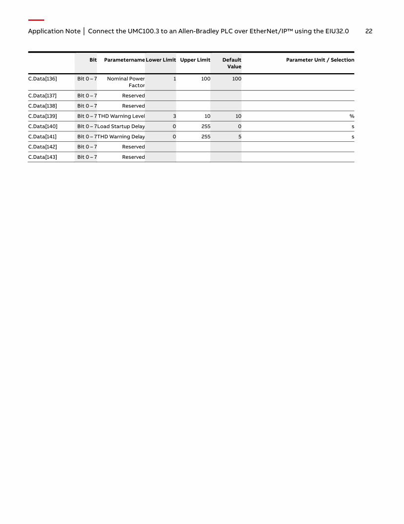
Bit Parametername Lower Limit Upper Limit Default Value
Parameter Unit / Selection
C.Data[136] Bit 0 – 7 Nominal Power Factor
1 100 100
C.Data[137] Bit 0 – 7 Reserved
C.Data[138] Bit 0 – 7 Reserved
C.Data[139] Bit 0 – 7 THD Warning Level 3 10 10 %
C.Data[140] Bit 0 – 7 Load Startup Delay 0 255 0 s
C.Data[141] Bit 0 – 7 THD Warning Delay 0 255 5 s
C.Data[142] Bit 0 – 7 Reserved
C.Data[143] Bit 0 – 7 Reserved

Contact us
— ABB STOTZ-KONTAKT GmbH Electrification Products Division Low Voltage Products and Systems Eppelheimer Straße 82 69123 Heidelberg,
You can find the address of your local sales organization on the ABB home page
abb.com/lowvoltage
Legal note We reserve the right to make technical changes or modify the contents of this document without prior notice. With regard to purchase orders, the agreed particulars shall prevail. ABB AG does not accept any responsibility whatsoever for potential errors or possible lack of information in this document.
We reserve all rights in this document and in the subject matter and illustrations contained therein. Any reproduction, disclosure to third parties or utilization of its contents – in whole or in parts – is forbidden without prior written consent of ABB AG.
Copyright© 2018 ABB
All rights reserved
2CD
C13
5060
M02
01
Rev
. A (0
3/20
18)