configuring drive parameters 3 - automation direct · pdf filethis ch apter will explain the...
TRANSCRIPT

Configuring Drive Parameters
In This Chapter.... page— Choosing a Programming Device .................... 2— Using Keypad Devices ..................................... 3— “D” Group: Monitoring Functions...................... 6— “F” Group: Main Profile Parameters ................. 8— “A” Group: Standard Functions ........................ 9— “B” Group: Fine Tuning Functions .................. 22— “C” Group: Intelligent Terminal Functions....... 32
3

Choosing a Programming DeviceC
onfig
urin
gD
rive
Par
amet
ers
3–2
Choosing a Programming DeviceIntroduction
Hitachi variable frequency drives (inverters) use the latest electronics technology for getting the right AC waveform to the motor at the right time. The benefits are many, including energy savings and higher machine output or productivity. The flexibility required to handle a broad range of applications has required ever more configurable options and parameters—inverters are now a complex industrial automation component. And this can make a product seem difficult to use, but the goal of this chapter is to make this easier for you.
As the powerup test in Chapter 2 demonstrated, you do not have to program very many parameters to run the motor. In fact, most applications would benefit only from program-ming just a few, specific parameters. This chapter will explain the purpose of each set of parameters, and help you choose the ones that are important to your application.
If you are developing a new application for the inverter and a motor, finding the right parameters to change is mostly an exercise in optimization. Therefore, it is okay to begin running the motor with a loosely tuned system. By making specific, individual changes and observing their effects, you can achieve a finely tuned system.
Introduction to Inverter ProgrammingThe front panel keypad is the first and best way to get to know the inverter’s capabilities. Every function or programmable parameter is accessible from the keypad. The other devices simply imitate the keypad’s layout and inverter access, while adding another valuable aspect to the system. For example, the Copy Unit can transfer one inverter’s parameter settings to another inverter, while still providing standard operator keypad control. In this way, you can use a variety of programming devices with basically the same keypad skills. The following table shows various programming options, the features unique to each device, and the cables required.
DevicePart
Number Parameter
Access
Parameter setting storage
Cables (choose one)
Part number Length
Inverter keypad — Monitor and program
EEPROM in inverter
— —
DOP Professional Software (for PC)
DOP–PRO Monitor and program
PC hard drive or diskette
(Included with software)
2 meters
Digital Operator/ Copy Unit
SRW–0EX Monitor and program
EEPROM in operator panel
ICS–1 1 meter
ICS–3 3 meters
Operator Monitor OPE–J Monitor only none on operator monitor
ICJ–1L 1 meter
ICJ–3L 3 meters

L100 InverterC
onfiguringD
rive Param
eters
3–3
Using Keypad DevicesInverter Front Panel Keypad
The L100 Series inverter front keypad contains all the elements for both monitoring and programming parameters. The keypad layout is pictured below. All other programming devices for the inverter have a similar key arrangement and function.
Key and Indicator Legend• Run/Stop LED - ON when the inverter output is ON and the motor is developing
torque (Run Mode), and OFF when the inverter output is OFF (Stop Mode).
• Program/Monitor LED - This LED is ON when the inverter is ready for parameter editing (Program Mode). It is OFF when the parameter display is monitoring data (Monitor Mode).
• Run Key Enable LED - is ON when the inverter is ready to respond to the Run key, OFF when the Run key is disabled.
• Run Key - Press this key to run the motor (the Run Enable LED must be ON first). Parameter F_04, Keypad Run Key Routing, determines whether the Run key gener-ates a Run FWD or Run REV command.
• Stop/Reset Key - Press this key to stop the motor when it is running (uses the programmed deceleration rate). This key will also reset an alarm that has tripped.
• Potentiometer - Allows an operator to directly set the motor speed when the potenti-ometer is enabled for output frequency control.
• Potentiometer Enable LED - ON when the potentiometer is enabled for value entry.
• Parameter Display - A 4-digit, 7-segment display for parameters and function codes.
• Display Units, Hertz/Amperes - One of these LEDs will be ON to indicate the units associated with the parameter display.
• Power LED - This LED is ON when the power input to the inverter is ON.
• Function Key - This key is used to navigate through the lists of parameters and functions for setting and monitoring parameter values.
• Up/Down ( , ) Keys - Use these keys alternately to move up or down the lists of parameter and functions shown in the display, and increment/decrement values.
• Store ( ) Key - When the unit is in Program Mode and you have edited a parameter value, press the Store key to write the new value to the EEPROM.
Function key Up/Down keys Store key
Hz
POWER
A
RUN
PRG
RUN STOPRESET
MIN MAX
HITACHI
FUNC. STR1 2
5 0.0
Parameter Display
Run/Stop LED
Program/Monitor LED
Run Key Enable LED
Run Key
Stop/Reset Key
Power LED
Display Units Hertz / Amperes LEDs
Potentiometer Enable LED
Potentiometer
1 2
STR

Using Keypad DevicesC
onfig
urin
gD
rive
Par
amet
ers
3–4
Keypad Navigational MapYou can use the inverter’s front panel keypad to navigate to any parameter or function. The diagram below shows the basic navigational map to access these items.
NOTE: The inverter 7-segment display shows lower case “b” and “d,” meaning the same as the upper case letters “B” and “D” used in this manual (for uniformity “A to F”).
NOTE: The Store Key saves the edited parameter (shown in the display) to the inverter’s EEPROM. Upload or download of parameters to/from external devices is accomplished through a different command—do not confuse Store with Download or Upload.
1 2
21
Edit
Writedata to
EEPROM
Increment/decrement
value
21
21
21
21
2
11
Select Parameter
2
Return to parameter
list
21
21
21
21
21
Edit Parameter
FUNC.
FUNC.
FUNC.
FUNC. FUNC.
STR
0 0 0.0
d 0 9
d 0 1
C - -
b - -
A - -
F 0 4
F 0 1
A 0 1
A 9 8
b 0 1
C 9 1
b 9 2
C 0 1
1 2 3.4
21
PRG LED=ONPRG LED=OFF
Program ModeMonitor Mode
Select Function or Group
powerdown
Store as powerup default
Display Data

L100 InverterC
onfiguringD
rive Param
eters
3–5
Operational ModesThe RUN and PGM LEDs tell just part of the story; Run Mode and Program Modes are independent modes, not opposite modes. In the state diagram to the right, Run alternates with Stop, and Program Mode alternates with Monitor Mode. This is a very important ability, for it shows that a technician can approach a running machine and change some parameters without shutting down the machine.
The occurrence of a fault during operation will cause the inverter to enter the Trip Mode as shown. An event such as an output overload will cause the inverter to exit the Run Mode and turn OFF its output to the motor. In the Trip Mode, any request to run the motor is ignored. You must clear the error by pressing the Stop/Reset switch. See page “Monitoring Trip Events, History, & Conditions” on page 6–5.
Run Mode EditsThe inverter can be in Run Mode (inverter output is controlling motor) and still allow you to edit certain parameters. This is useful in applications that must run continuously, yet need some inverter parameter adjustment.
The parameter tables in this chapter have a column titled “Run Mode Edit.” An Ex mark ✘ means the parameter cannot be edited; a Check mark ✔ means the parameter can be edited. The Software Lock Setting (parameter B_31) determines when the Run Mode access permission is in effect and access permission in other conditions, as well. It is the responsibility of the user to choose a useful and safe software lock setting for the inverter operating conditions and personnel. Please refer to “Software Lock Mode” on page 3–26 for more information.
Control AlgorithmsThe motor control program in the L100 inverter has two PWM sinusoidal switching algorithms. The intent is that you select the best algorithm for the motor characteristics in your application. Both algorithms generate the frequency output in a unique way. Once configured, the algorithm is the basis for other parameter settings as well (see “Torque Control Algorithms” on page 3–13). Therefore, choose the best algorithm early in your application design process.
RUN
STOPRESET
FUNC.
Run Stop
Monitor Program
RUN
STOPRESET
STOPRESET
Run Stop
TripFault
Fault
Run Mode Edit
✘
✔
Output
Variable freq. control,constant torque
Variable freq. control,reduced torque
Inverter Control Algorithms

“D” Group: Monitoring FunctionsC
onfig
urin
gD
rive
Par
amet
ers
3–6
“D” Group: Monitoring FunctionsParameter Monitoring Functions
You can access important system parameter values with the “D” Group monitoring functions, whether the inverter is in Run Mode or Stop Mode. After selecting the function code number for the parameter you want to monitor, press the Function key once to show the value on the display. In Functions D_05 and D_06, the intelligent terminals use individual segments of the display to show ON/OFF status.
If the inverter display is set to monitor a parameter and powerdown occurs, the inverter stores the present monitor function setting. For your convenience, the display automati-cally returns to the previously monitored parameter upon the next powerup.
“D” Function Run Mode Edit
Range and
UnitsFunc.Code
Name /SRW Display
Description
D_01 Output frequency monitor
Real-time display of output frequency to motor, from 0.0 to 360.0 Hz
— 0.0 to 360.0 Hz
FM 0000.00Hz
D_02 Output current monitor Filtered display of output current to motor (100 ms internal filter time constant)
— A
Im 0.0A 0.0%
D_03 Rotation direction monitor
Three different indications:“F”..... Forward“| |” .. Stop“r”..... Reverse
— —
Dir STOP
D_04 Process variable (PV), PID feedback monitor
Displays the scaled PID process variable (feedback) value (A_75 is scale factor)
— —
PID-FB 0000.00%
D_05 Intelligent input terminal status
Displays the state of the intelli-gent input terminals:
— —
TERM LLL LLLLLL
D_06 Intelligent output terminal status
Displays the state of the intelli-gent output terminals:
— —
TERM LLL LLLLLL
ON
OFF
123456Terminal numbers
ON
OFF
1112Terminal numbers
AL

L100 InverterC
onfiguringD
rive Param
eters
3–7
Trip Event and History MonitoringThe trip event and history monitoring feature lets you cycle through related information using the keypad. See “Monitoring Trip Events, History, & Conditions” on page 6–5 for more details.
D_07 Scaled output frequency monitor
Displays the output frequency scaled by the constant in B_86. Decimal point indicates range:XX.XX 0.01 to 99.99XXX.X 100.0 to 999.9XXXX. 1000 to 9999XXXX 10000 to 99990
— Hz
/Hz01.0 0.00
“D” Function Run Mode Edit
Range and
UnitsFunc.Code
Name /SRW Display
Description
“D” Function Run Mode Edit
Range and
UnitsFunc.Code
Name /SRW Display
Description
D_08 Trip event monitor Displays the current trip event. information.
— —
ERR1 EEPROM
ERR1 0.0Hz
ERR1 0.0A
ERR1 324.3Vdc
ERR1 RUN 000000H
D_09 Trip history monitor Displays the previous two events and their causes.
— —
ERR2 EEPROM
ERR2 0.0Hz
ERR2 0.0A
ERR2 330.0Vdc
ERR2 RUN 000000H
ERR3 EEPROM
ERR3 0.0Hz
ERR3 0.0A
ERR3 328.7Vdc
ERR3 RUN 000000H
— Cumulative operation RUN time monitor
Displays total time the inverter has been in RUN mode in hours.
— hours
RUN 000000H
— Trip count Displays cumulative number of trip events.
— trips
ERROR COUNT 009

“F” Group: Main Profile ParametersC
onfig
urin
gD
rive
Par
amet
ers
3–8
“F” Group: Main Profile ParametersThe basic frequency (speed) profile is defined by parameters contained in the “F” Group as shown to the right. The set running frequency is in Hz, but accelera-tion and deceleration are specified in the time duration of the ramp (from zero to maximum frequency, or from maximum frequency to zero). The motor direction parameter determines whether the keypad Run key produces a FWD or REV command. This parameter does not affect the intelli-gent terminal [FWD] and [REV] functions, which you configure separately.
Acceleration 1 and Deceleration 1 are the standard default accel and decel values for the main profile. Accel and decel values for an alternative profile are specified by using parameters A_92 through A_93. The motor direction selection (F_04) determines the direction of rotation as commanded only from the keypad.
Output frequency
F 01
F 02 F 03
t0
“F” Function Run Mode Edit
Defaults
Func.Code
Name /SRW Display
Description–FE (CE)
–FU (UL)
–FR (Jpn)
Units
F_01 Output frequency setting
Standard default target frequency that determines constant motor speed,range is 0 to 360 Hz
✔ 0.0 0.0 0.0 Hz
TM 000.0 0.0Hz
F_02 Acceleration 1 time setting
Standard default acceleration,range is 0.1 to 3000 sec.
✔ 10.0 10.0 10.0 sec.
ACC 1 0010.0s
F_03 Deceleration 1 time setting
Standard default deceleration,range is 0.1 to 3000 sec.
✔ 10.0 10.0 10.0 sec.
DEC 1 0010.0s
F_04 Keypad Run key routing
Two options; select codes:00... Forward01... Reverse
✘ 00 00 00 —
INIT DOPE FWD

L100 InverterC
onfiguringD
rive Param
eters
3–9
“A” Group: Standard FunctionsBasic Parameter Settings
These settings affect the most fundamental behavior of the inverter—the outputs to the motor. The frequency of the inverter’s AC output determines the motor speed. You may select from three different sources for the reference speed. During application develop-ment you may prefer using the potentiometer, but you may switch to an external source (control terminal setting) in the finished application, for example.
The base frequency and maximum frequency settings interact according to the graph below (left). The inverter output operation follows the constant V/f curve until it reaches the full-scale output voltage. This initial straight line is the constant-torque part of the operating characteristic. The horizontal line over to the maximum frequency serves to let the motor run faster, but at a reduced torque. If you want the motor to output constant torque over its entire operating range (limited to the motor nameplate voltage and frequency rating), then set the base frequency and maximum frequency equal as shown (below right).
Base Frequency
Maximum Frequency
Base frequency = maximum frequency
A 03 A 04A 03
A 04V V100% 100%
f f
Constant torque
00
“A” Function Run Mode Edit
Defaults
Func.Code
Name /SRW Display
Description–FE (CE)
–FU (UL)
–FR (Jpn)
Units
A_01 Frequency source setting
Three options; select codes:00 ...Keypad potentiometer01 ...Control terminal02 ...Function F01 setting
✘ 01 01 00 —
F-SET-SELECT TRM
A_02 Run command source setting
Two options; select codes:01 ...Control terminal02 ...Run key on keypad, or digital operator
✘ 01 01 02 —
F/R SELECT TRM
A_03 Base frequency setting Settable from 50 Hz to the maximum frequency
✘ 50.0 60.0 60.0 Hz
F-BASE 060Hz
A_04 Maximum frequency setting
Settable from the base frequency up to 360 Hz
✘ 50.0 60.0 60.0 Hz
F-MAX 060Hz

“A” Group: Standard FunctionsC
onfig
urin
gD
rive
Par
amet
ers
3–10
Analog Input SettingsThe inverter has the capability to accept an external analog input that can command the output frequency to the motor. Voltage input (0 –10V) and current input (4–20mA) are available on separate terminals ([O] and [OI], respectively). Terminal [L] serves as signal ground for the two analog inputs. The analog input settings adjust the curve characteristics between the analog input and the frequency output.
In the graph below (left), A_13 and A_14 select the active portion of the input voltage or current range. The parameters A_11 and A_12 select the start and end frequency of the converted output frequency range, respectively. Together, these four parameters define a line segment as shown (below, right). When the line does not begin at the origin, A_15 defines whether the inverter outputs 0Hz or the A_11 frequency when the analog input value is less than the A_13 setting (determines the non-linear part of the translation).
A 12
A 11
A 13 A 14
A 12
A 11
A_15 = 00
A_15 = 01
A 13 A 14
Frequency Frequency
0V4mA
10V20mA
% Input scale % Input scale
0V4mA
10V20mA
0 0 %%
“A” Function Run Mode Edit
Defaults
Func.Code
Name /SRW Display
Description–FE (CE)
–FU (UL)
–FR (Jpn)
Units
A_11 O–L input active range start frequency
The output frequency corre-sponding to the analog input range starting point
✘ 0.0 0.0 0.0 Hz
IN EXS 000.0Hz
A_12 O–L input active range end frequency
The output frequency corre-sponding to the analog input range ending point
✘ 0.0 0.0 0.0 Hz
IN EXE 000.0Hz
A_13 O–L input active range start voltage
The starting point (offset) for the active analog input range
✘ 0 0 0 %
IN EX%S 000%
A_14 O–L input active range end voltage
The ending point (offset) for the active analog input range
✘ 100 100 100 %
IN EX%E 100%
A_15 O–L input start frequency enable
Two options; select codes:00 ...Use offset (A_11 value)01 ...Use 0 Hz
✘ 01 01 01 —
IN LEVEL 0Hz

L100 InverterC
onfiguringD
rive Param
eters
3–11
A_16 External frequency filter time constant
Range n = 1 to 8, where n = number of samples for avg.
✘ 8 8 8 Sam-ples
IN F-SAMP 8
“A” Function Run Mode Edit
Defaults
Func.Code
Name /SRW Display
Description–FE (CE)
–FU (UL)
–FR (Jpn)
Units

“A” Group: Standard FunctionsC
onfig
urin
gD
rive
Par
amet
ers
3–12
Multi-speed and Jog Frequency SettingThe L100 inverter has the capability to store and output up to 16 preset frequencies to the motor (A_20 to A_35). As in traditional motion terminology, we call this multi-speed profile capability. These preset frequencies are selected by means of digital inputs to the inverter. The inverter applies the current acceleration or deceleration setting to change from the current output frequency to the new one.
The jog speed setting is used whenever the Jog command is active. The jog speed setting range is arbitrarily limited to 10 Hz, to provide safety during manual operation. The acceleration to the jog frequency is instantaneous, but you can choose from three modes for the best method for stopping the jog operation.
“A” Function Run Mode Edit
Defaults
Func.Code
Name /SRW Display
Description–FE (CE)
–FU (UL)
–FR (Jpn)
Units
A_20 Multi-speed frequency setting
Defines the first speed of a multi-speed profile, range is0 to 360 Hz
✔ 0 0 0 Hz
SPD FS 000.0Hz
A_21 to
A_35
Multi-speed frequency settings
Defines 15 more speeds,range is 0 to 360 Hz.A_21= Speed 2...A_35 = Speed 16
✔ seenextrow
seenextrow
seenextrow
Hz
SPD 1 000.0Hz
SPD 2 000.0Hz
SPD 3 000.0Hz
SPD 4 000.0Hz
SPD 5 000.0Hz
SPD 6 000.0Hz
SPD 7 000.0Hz
SPD 8 000.0Hz
SPD 9 000.0Hz
SPD 10 000.0Hz
SPD 11 000.0Hz
SPD 12 000.0Hz
SPD 13 000.0Hz
SPD 14 000.0Hz
SPD 15 000.0Hz
A_21A_22A_23A_24A_25A_26A_27A_28A_29A_30A_31A_32A_33A_34A_35
000000000000000
000000000000000
5101520304050600000000
A_38 Jog frequency setting Defines limited speed for jog, range is 0.5 to 9.99 Hz
✔ 1.0 1.0 1.0 Hz
Jogging 01.00Hz
A_39 Jog stop mode Define how end of jog stops the motor; three options:00 ...Free-run stop01 ...Controlled deceleration02 ...DC braking to stop
✘ 00 00 00 —
Jog Mode 0

L100 InverterC
onfiguringD
rive Param
eters
3–13
Torque Control AlgorithmsThe inverter generates the motor output according to the V/f algorithm selected. Parameter A_44 selects the inverter algorithm for generating the frequency output, as shown in the diagram to the right. The factory default is 00 (constant torque).
Review the following description to help you choose the best torque control algorithm for your application.
• The built-in V/f curves are oriented toward developing constant torque or variable torque characteristics (see graphs below). You can select either constant torque or reduced torque V/f control.
Constant and Variable (Reduced) Torque – The graph below (left) shows the constant torque characteristic from 0Hz to the base frequency A_03. The voltage remains constant for output frequencies higher than the base frequency. The graph below (right) shows the general variable (reduced) torque curve. The range from 0Hz to the base frequency is the variable characteristic.
Torque Boost – The Constant and Variable Torque algorithms feature an adjustable torque boost curve. When the motor load has a lot of inertia or starting friction, you may need to increase the low frequency starting torque characteristics by boosting the voltage above the normal V/f ratio (shown at right). The boost is applied from zero to 1/2 the base frequency. You set the breakpoint of the boost (point A on the graph) by using parameters A_42 and A_43. The manual boost is calculated as an addition to the standard straight V/f line (constant torque curve).
Be aware that running the motor at a low speed for a long time can cause motor overheating. This is particularly true when manual torque boost is ON, or if the motor relies on a built-in fan for cooling.
Output
A44V/f control,
constant torque
V/f control,variable torque
00
01
Inverter Torque Control Algorithms
Constant torqueA_44 = 00V100%
Hz0
Variable torqueA_44 = 01V100%
Hz0Basefreq.
Max.freq.
Basefreq.
Max.freq.
f base = 60Hz
Torque boost
A_42 = 11
A_43 = 10 (%)
V
Hz
100%
11.8%
30.0Hz6.0Hz
A
0

“A” Group: Standard FunctionsC
onfig
urin
gD
rive
Par
amet
ers
3–14
Voltage Gain – Using parameter A_45 you can modify the voltage gain of the inverter (see graph at right). This is specified as a percent-age of the full scale setting (Automatic Voltage Regulation) AVR level in parameter F_03. The gain can be set from 50% to 100%. It should be adjusted in accordance with the motor specifi-cations.
The following table shows the methods of torque control selection.
A 45
V100%
50%
Hz
Voltage Gain
0
“A” Function Run Mode Edit
Defaults
Func.Code
Name /SRW Display
Description–FE (CE)
–FU (UL)
–FR (Jpn)
Units
A_41 Torque boost method selection
Two options:00 ...Manual torque boost01 ...Automatic torque boost
✘ 00 00 00 —
V-Boost Mode 0
A_42 Manual torque boost value
Can boost starting torque between 0 and 99% above normal V/f curve, from 0 to1/2 base frequency
✔ 11 11 11 —
V-Boost code 11
A_43 Manual torque boost frequency adjustment
Sets the frequency of the V/f breakpoint A in graph (top of previous page) for torque boost
✔ 10.0 10.0 10.0 %
V-Boost F 10.0%
A_44 V/f characteristic curve selection
Two available V/f curves;three select codes:00 ...Constant torque01 ...Reduced torque
✘ 00 00 00 —
CONTROL SLV
A_45 V/f gain setting Sets voltage gain of the inverter from 50 to 100%
✔ 100 100 100 %
V-Gain 100%

L100 InverterC
onfiguringD
rive Param
eters
3–15
DC Braking SettingsThe DC braking feature can provide additional stopping torque when compared to a normal deceleration to a stop. DC braking is particularly useful at low speeds when normal decelera-tion torque is minimal. When you enable DC braking, the inverter injects a DC voltage into the motor windings during deceleration below a frequency you can specify (A_52). The braking power (A_54) and duration (A_55) can both be set. You can optionally specify a wait time before DC braking (A_53), during which the motor will free run (coast).
CAUTION: Be careful to avoid specifying a braking time that is long enough to cause motor overheating. If you use DC braking, we recommend using a motor with a built-in thermistor, and wiring it to the inverter’s thermistor input (see “Thermistor Thermal Protection” on page 4–20). Also refer to the motor manufacturer’s specifications for duty-cycle recommendations during DC braking.
DC brakingFree runRunning
A 53 A 55
t0
+
–
“A” Function Run Mode Edit
Defaults
Func.Code
Name /SRW Display
Description–FE (CE)
–FU (UL)
–FR (Jpn)
Units
A_51 DC braking enable Two options; select codes:00 ...Disable01 ...Enable
✘ 00 00 00 —
DCB SW OFF
A_52 DC braking frequency setting
The frequency at which DC braking occurs,range is 0.5 to 10 Hz
✘ 0.5 0.5 0.5 Hz
DCB F 00.5Hz
A_53 DC braking wait time The delay from the end of Run command to start of DC braking (motor free runs until DC braking begins)
✘ 0.0 0.0 0.0 sec.
DCB WAIT 0.0s
A_54 DC braking during deceleration
Applied level of DC braking force, settable from 0 to 100%
✘ 0 0 0 %
DCB V 000
A_55 DC braking time for deceleration
Sets the duration for DC braking, range is 0.1 to 60.0 seconds
✘ 0.0 0.0 0.0 sec.
DCB T 00.0s

“A” Group: Standard FunctionsC
onfig
urin
gD
rive
Par
amet
ers
3–16
Frequency-related FunctionsFrequency Limits – Upper and lower limits can be imposed on the inverter output frequency. These limits will apply regardless of the source of the speed refer-ence. You can configure the lower frequency limit to be greater than zero as shown in the graph to the right. The upper limit must not exceed the rating of the motor or capability of the machinery.
Upperlimit
Frequency command
Lowerlimit
Settablerange
A 61
A 62
Outputfrequency
0
“A” Function Run Mode Edit
Defaults
Func.Code
Name /SRW Display
Description–FE (CE)
–FU (UL)
–FR (Jpn)
Units
A_61 Frequency upper limit setting
Sets a limit on output frequency less than the maximum frequency (A_04) Range is 0.5 to 360.0 Hz0.0 ..setting is disabled>0.1setting is enabled
✘ 0.0 0.0 0.0 Hz
LIMIT H 000.0Hz
A_62 Frequency lower limit setting
Sets a limit on output frequency greater than zero Range is 0.5 to 360.0 Hz0.0 ..setting is disabled>0.1setting is enabled
✘ 0.0 0.0 0.0 Hz
LIMIT L 000.0Hz
L100 InverterC
onfiguringD
rive Param
eters
3–17
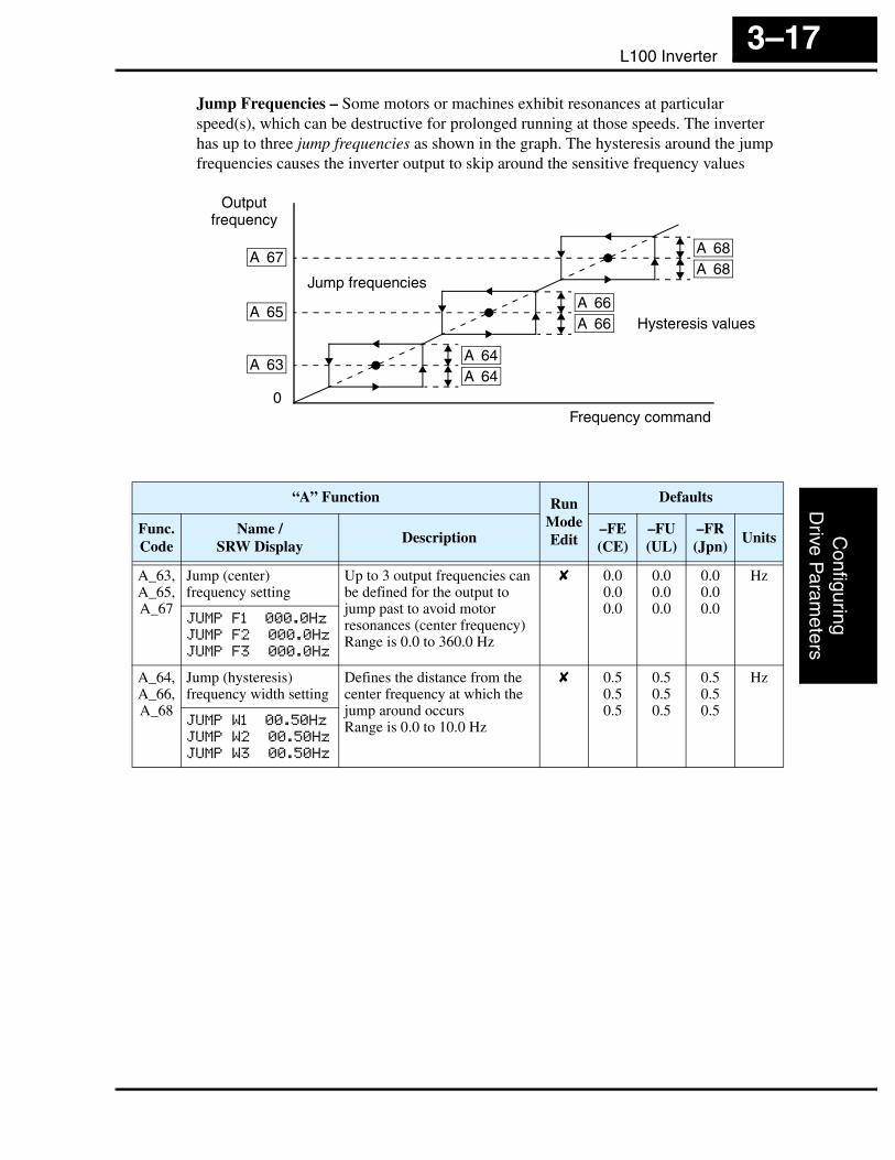
Jump Frequencies – Some motors or machines exhibit resonances at particular speed(s), which can be destructive for prolonged running at those speeds. The inverter has up to three jump frequencies as shown in the graph. The hysteresis around the jump frequencies causes the inverter output to skip around the sensitive frequency values
Jump frequencies
A 63A 64
Outputfrequency
Frequency command
A 64
A 66A 66
A 68A 68
A 65
A 67
Hysteresis values
0
“A” Function Run Mode Edit
Defaults
Func.Code
Name /SRW Display
Description–FE (CE)
–FU (UL)
–FR (Jpn)
Units
A_63,A_65,A_67
Jump (center) frequency setting
Up to 3 output frequencies can be defined for the output to jump past to avoid motor resonances (center frequency)Range is 0.0 to 360.0 Hz
✘ 0.00.00.0
0.00.00.0
0.00.00.0
Hz
JUMP F1 000.0Hz
JUMP F2 000.0Hz
JUMP F3 000.0Hz
A_64,A_66,A_68
Jump (hysteresis) frequency width setting
Defines the distance from the center frequency at which the jump around occursRange is 0.0 to 10.0 Hz
✘ 0.50.50.5
0.50.50.5
0.50.50.5
Hz
JUMP W1 00.50Hz
JUMP W2 00.50Hz
JUMP W3 00.50Hz

“A” Group: Standard FunctionsC
onfig
urin
gD
rive
Par
amet
ers
3–18
PID ControlWhen enabled, the built-in PID loop calculates an ideal inverter output value to cause a loop feedback process variable (PV) to move closer in value to the setpoint (SP). The current frequency command serves as the SP. The PID loop algorithm will read the analog input for the process variable (you specify the current or voltage input) and calcu-late the output.
• A scale factor in A_75 lets you multiply the PV by a factor, converting it into engineering units for the process.
• Proportional, integral, and derivative gains are all adjustable.
• See “PID Loop Operation” on page 4–32 for more information.
NOTE: The setting A_73 for the integrator is the integrator’s time constant Ti, not the gain. The integrator gain Ki = 1/Ti. When you set A_73 = 0, the integrator is disabled.
“A” Function Run Mode Edit
Defaults
Func.Code
Name /SRW Display
Description–FE (CE)
–FU (UL)
–FR (Jpn)
Units
A_71 PID Enable Enables PID function,two option codes:00 ...PID Disable01 ...PID Enable
✘ 00 00 00 —
PID SW OFF
A_72 PID proportional gain Proportional gain has a range of 0.2 to 5.0
✘ 1.0 1.0 1.0 —
PID P 1.0
A_73 PID integral time constant
Integral time constant has a range of 0.0 to 150 seconds
✘ 1.0 1.0 1.0 sec.
PID I 001.0s
A_74 PID derivative time constant
Derivative time constant has a range of 0.0 to 100 seconds
✘ 0.0 0.0 0.0 sec.
PID D 00.0
A_75 PV scale conversion Process Variable (PV) scale factor (multiplier), range of0.01 to 99.99
✘ 1.00 1.00 1.00 —
PID CONV 01.00
A_76 PV source setting Selects source of Process Variable (PV), option codes:00 ...[OI] terminal (current in)01 ...[O] terminal (voltage in)
✘ 00 00 00 —
PID INPT CUR

L100 InverterC
onfiguringD
rive Param
eters
3–19
Automatic Voltage Regulation (AVR) FunctionThe automatic voltage regulation (AVR) feature keeps the inverter output waveform at a relatively constant amplitude during power input fluctuations. This can be useful if the installation is subject to input voltage fluctuations. However, the inverter cannot boost its motor output to a voltage higher than the power input voltage. If you enable this feature, be sure to select the proper voltage class setting for your motor.
“A” Function Run Mode Edit
Defaults
Func.Code
Name /SRW Display
Description–FE (CE)
–FU (UL)
–FR (Jpn)
Units
A_81 AVR function select Automatic (output) voltage regulation, selects from three type of AVR functions, three option codes:00 ...AVR enabled01 ...AVR disabled02 ...AVR enabled except during deceleration
✘ 02 00 02 —
AVR MODE DOFF
A_82 AVR voltage select 200V class inverter settings:.......200/220/230/240400V class inverter settings:.......380/400/415/440/460
✘ 230/400
230/460
200/400
V
AVR AC 230V

“A” Group: Standard FunctionsC
onfig
urin
gD
rive
Par
amet
ers
3–20
Second Acceleration and Deceleration FunctionsThe L100 inverter features two-stage acceleration and deceleration ramps. This gives flexibility in the profile shape. You can specify the frequency transition point, the point at which the standard acceleration (F_02) or deceleration (F_03) changes to the second acceleration (A_92) or deceleration (A_93). Select a transition frequency method via A_94 as depicted below.
NOTE: For A_95 and A_96, if you set a very rapid Acc1 or Dec1 time (less than 1.0 second), the inverter may not be able to change rates to Acc2 or Dec2 before reaching the target frequency. In that case, the inverter decreases the rate of Acc1 or Dec1 in order to achieve the second ramp to the target frequency.
Accel 1
Accel 2
2CH input
Frequency transition point
A 95
A_94 = 00 A_94 = 01
Outputfrequency
Outputfrequency
tt
Accel 1
Accel 2
t
Transition via 2CH input Transition via freq. level
0 0
10
“A” Function Run Mode Edit
Defaults
Func.Code
Name /SRW Display
Description–FE (CE)
–FU (UL)
–FR (Jpn)
Units
A_92 Acceleration (2) time setting
Duration of 2nd segment of acceleration, range is:0.1 to 3000 sec.
✔ 15.0 15.0 15.0 sec.
ACC 2 0015.0s
A_93 Deceleration (2) time setting
Duration of 2nd segment of deceleration, range is:0.1 to 3000 sec.
✔ 15.0 15.0 15.0 sec.
DEC 2 0015.0s
A_94 Select method to switch to Acc2/Dec2 profile
Two options for switching from 1st to 2nd accel/decel:00 ...2CH input from terminal01 ...transition frequency
✘ 00 00 00 —
ACC CHG TM
A_95 Acc1 to Acc2 frequency transition point
Output frequency at which Accel1 switches to Accel2,range is 0.0 to 360.0 Hz
✘ 0.0 0.0 0.0 Hz
ACC CHFr 000.0Hz
A_96 Dec1 to Dec2 frequency transition point
Output frequency at which Decel1 switches to Decel2,range is 0.0 to 360.0 Hz
✘ 0.0 0.0 0.0 Hz
DEC CHFr 000.0Hz

L100 InverterC
onfiguringD
rive Param
eters
3–21
Accel/DecelStandard acceleration and deceleration is linear. The inverter CPU can also calculate an S-curve acceleration or deceleration curve as shown. This profile is useful for favoring the load characteristics in particu-lar applications.
Curve settings for acceleration and decel-eration are independently selected. To enable the S-curve, use function A_97 (acceleration) and A_98 (deceleration).
Acceleration period
S-curve
Linear
Accel. curve selection
Target freq.
Outputfrequency
t0
A_97 = 00
A_97 = 01
“A” Function Run Mode Edit
Defaults
Func.Code
Name /SRW Display
Description–FE (CE)
–FU (UL)
–FR (Jpn)
Units
A_97 Acceleration curve selection
Set the characteristic curve of Acc1 and Acc2, two options:00 ...linear01 ...S-curve
✘ 00 00 00 —
ACCEL LINE L
A_98 Deceleration curve selection
Set the characteristic curve of Acc1 and Acc2, two options:00 ...linear01 ...S-curve
✘ 00 00 00 —
DEC LINE L

“B” Group: Fine Tuning FunctionsC
onfig
urin
gD
rive
Par
amet
ers
3–22
“B” Group: Fine Tuning FunctionsThe “B” Group of functions and parameters adjust some of the more subtle but useful aspects of motor control and system configuration.
Automatic Restart ModeThe restart mode determines how the inverter will resume operation after a fault causes a trip event. The four options provide advantages for various situations. Frequency matching allows the inverter to read the motor speed by virtue of its residual magnetic flux and restart the output at the corresponding frequency. The inverter can attempt a restart a certain number of times depending on the particular trip event:
• Over-current trip, restart up to 3 times
• Over-voltage trip, restart up to 3 times
• Under-voltage trip, restart up to 16 times
When the inverter reaches the maximum number of restarts (3 or 16), you must power-cycle the inverter to reset its operation.
Other parameters specify the allowable under-voltage level and the delay time before restarting. The proper settings depend on the typical fault conditions for your applica-tion, the necessity of restarting the process in unattended situations, and whether restart-ing is always safe.
Input power
Motor speed
B 02
B 03
Power fail t0
0
Power failure < allowable power fail time (B_02), inverter resumes
0
Inverter output
free-running
Input power
Motor speed
B 02
t0
0
Power failure > allowable power fail time (B_02), inverter trips
0
Inverter output
free-running
Allowablepower fail time
Retry wait time
Power failAllowable
power fail time

L100 InverterC
onfiguringD
rive Param
eters
3–23
“B” Function Run Mode Edit
Defaults
Func.Code
Name /SRW Display
Description–FE (CE)
–FU (UL)
–FR (Jpn)
Units
B_01 Selection of restart mode
Select inverter restart method, four option codes:00 ...Alarm output after trip, no automatic restart01 ...Restart at 0Hz02 ...Resume operation after frequency matching03 ...Resume previous freq. after freq. matching, then decelerate to stop and display trip info.
✘ 00 00 00 —
IPS POWR ALM
B_02 Allowable under-voltage power failure time
The amount of time a power input under-voltage can occur without tripping the power failure alarm. Range is 0.3 to 25 sec. If under-voltage exists longer than this time, the inverter trips, even if the restart mode is selected.
✘ 1.0 1.0 1.0 sec.
IPS UVTIME 01.0s
B_03 Retry wait time before motor restart
Time delay after under-voltage condition goes away, before the inverter runs motor again.Range is 0.3 to 100 seconds.
✘ 1.0 1.0 1.0 sec.
IPS WAIT 001.0s

“B” Group: Fine Tuning FunctionsC
onfig
urin
gD
rive
Par
amet
ers
3–24
Electronic Thermal Overload Alarm SettingThe thermal overload detection protects the inverter and motor from overheating due to an excessive load. It uses a current/inverse time curve to determine the trip point.
First, use B_13 to select the torque charac-teristic that matches your load. This allows the inverter to utilize the best thermal overload characteristic for your application.
The torque developed in a motor is directly proportional to the current in the windings, which is also proportional to the heat generated (and temperature, over time). Therefore, you must set the thermal overload threshold in terms of current (amperes) for parameter B_12. The range is 50% to 120% of the rated current for each inverter model. If the current exceeds the level you specify, the inverter will trip and log an event (error E05) in the history table. The inverter turns the motor output OFF when tripped.
WARNING: When parameter B_12, level of electronic thermal setting, is set to device FLA rating (Full Load Ampere nameplate rating), the device provides solid state motor overload protection at 115% of device FLA or equivalent. Parameter B_12, level of electronic thermal setting, is a variable parameter.
NOTE: For inverter models 005NFE, 011NFE, and 030HFE, the thermal value is less than the rated amperes (is the same as models 004NFE, 007NFE, and 040HFE respec-tively). Therefore, be sure to set the electronic thermal overload according to the actual motor driven by the particular inverter.
Output frequency
Constant torque
Reducedtorque
B_13 = 01
B_13 = 00
Torque
5 20 60 120 Hz
100%
80%
60%
0
“B” Function Run Mode Edit
Defaults
Func.Code
Name /SRW Display
Description–FE (CE)
–FU (UL)
–FR (Jpn)
Units
B_12 Level of electronic thermal setting
Set a level between 50% and 120% for the rated inverter current.
✘ Rated current for each inverter model
*See note
%
E-THM LVL 03.00A
B_13 Electronic thermal characteristic
Select from two curves, option codes:00 ...Reduced torque01 ...Constant torque
✘ 01 01 00 —
E-THM CHAR CRT
L100 InverterC
onfiguringD
rive Param
eters
3–25
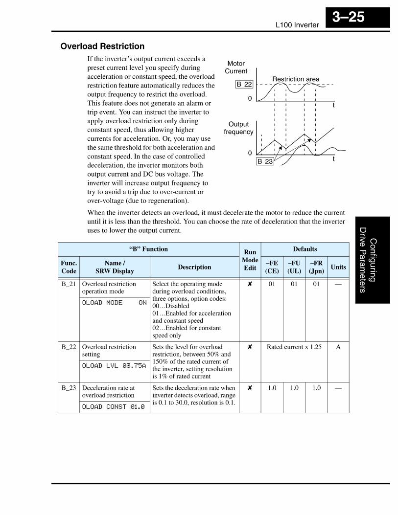
Overload RestrictionIf the inverter’s output current exceeds a preset current level you specify during acceleration or constant speed, the overload restriction feature automatically reduces the output frequency to restrict the overload. This feature does not generate an alarm or trip event. You can instruct the inverter to apply overload restriction only during constant speed, thus allowing higher currents for acceleration. Or, you may use the same threshold for both acceleration and constant speed. In the case of controlled deceleration, the inverter monitors both output current and DC bus voltage. The inverter will increase output frequency to try to avoid a trip due to over-current or over-voltage (due to regeneration).
When the inverter detects an overload, it must decelerate the motor to reduce the current until it is less than the threshold. You can choose the rate of deceleration that the inverter uses to lower the output current.
Motor Current
Output frequency
B 22
B 23 t
t
Restriction area
0
0
“B” Function Run Mode Edit
Defaults
Func.Code
Name /SRW Display
Description–FE (CE)
–FU (UL)
–FR (Jpn)
Units
B_21 Overload restriction operation mode
Select the operating mode during overload conditions, three options, option codes:00 ...Disabled01 ...Enabled for acceleration and constant speed02 ...Enabled for constant speed only
✘ 01 01 01 —
OLOAD MODE ON
B_22 Overload restriction setting
Sets the level for overload restriction, between 50% and 150% of the rated current of the inverter, setting resolution is 1% of rated current
✘ Rated current x 1.25 A
OLOAD LVL 03.75A
B_23 Deceleration rate at overload restriction
Sets the deceleration rate when inverter detects overload, range is 0.1 to 30.0, resolution is 0.1.
✘ 1.0 1.0 1.0 —
OLOAD CONST 01.0

“B” Group: Fine Tuning FunctionsC
onfig
urin
gD
rive
Par
amet
ers
3–26
Software Lock ModeThe software lock function keeps personnel from accidentally changing parameters in the inverter memory. Use B_31 to select from various protection levels.
The table below lists all combinations of B_31 option codes and the ON/OFF state of the [SFT] input. Each Check ✔ or Ex ✘ indicates whether the corresponding parameter(s) can be edited. The Standard Parameters column below shows access is permit-ted for some lock modes. These refer to the parameter tables throughout this chapter, each of which includes a column titled Run Mode Edit as shown to the right. The marks (Check ✔ or Ex ✘) under the “Run Mode Edit” column title indicate whether access applies to each parameter as defined in the table below. In some lock modes, you can edit only F_01 and the Multi-speed parameter group that includes A_20, A220, A_21–A_35, and A_38 (Jog). However, it does not include A_19, Multi-speed operation selection. The editing access to B_31 itself is unique, and is specified in the right-most two columns below.
NOTE: Since the software lock function B_31 is always accessible, this feature is not the same as password protection used in other industrial control devices.
B_31 Lock Mode
[SFT] Intelligent
Input
Standard ParametersF_01 and
Multi-SpeedB_31
Stop Run Stop & Run Stop Run
00 OFF ✔ Run mode edit access
✔ ✔ ✘
ON ✘ ✘ ✘ ✔ ✘
01 OFF ✔ Run mode edit access
✔ ✔ ✘
ON ✘ ✘ ✔ ✔ ✘
02 (ignored) ✘ ✘ ✘ ✔ ✘
03 (ignored) ✘ ✘ ✔ ✔ ✘
Run Mode Edit
✘
✔

L100 InverterC
onfiguringD
rive Param
eters
3–27
NOTE: To disable parameter editing when using B_31 lock modes 00 and 01, assign the [SFT] function to one of the intelligent input terminals.See “Software Lock” on page 4–17.
“B” Function Run Mode Edit
Defaults
Func.Code
Name /SRW Display
Description–FE (CE)
–FU (UL)
–FR (Jpn)
Units
B_31 Software lock mode selection
Prevents parameter changes, in four options, option codes:00 ...all parameters except B_31 are locked when [SFT] terminal is ON01 ...all parameters except B_31 and output frequency F01 when SFT from terminal is ON02 ...all parameters except B_31 are locked03 ...all parameters except B_31 and output frequency F_01 setting are locked
✘ 01 01 01 —
S-LOCK MD1

“B” Group: Fine Tuning FunctionsC
onfig
urin
gD
rive
Par
amet
ers
3–28
Miscellaneous SettingsThe miscellaneous settings include scaling factors, initialization modes, and others. This section covers some of the most important settings you may need to configure.
B_32: Reactive current setting – The inverter’s D_02 monitor function displays the motor current. The display accuracy is normally ±20%, provided that the following conditions exist:
• A single motor with standard frame size and characteristics is connected
• The inverter’s output frequency is at 50% or higher of the maximum output frequency
• The inverter’s output current is within the rated current
However, it will be necessary to calibrate the display accuracy via B_32 adjustment of the internal no-load reactive motor current if any of these conditions exist:
• The motor is smaller than the standard maximum recommended for the inverter
• The motor is a two-pole motor type
• Two or more motors are connected in parallel to the inverter (be sure to multiply the current by the number of motors when setting B_32)
If you do not know the reactive or no-load current for your particular motor, you can calibrate the L100 as follows:
1. Connect the motor directly across the AC line with no load attached to the shaft.
WARNING: Use a disconnect switch or breaker to ensure that you do not connect the motor or inverter to live wiring. Otherwise, there is the danger of electric shock.
2. Run the motor, and measure the no-load current with an AC current clamp, recording the value.
3. Disconnect the motor from the AC line connection, and connect the motor to the L100 inverter output (still with no load attached).
4. Run the motor at the base frequency (value of parameter A_03), and monitor the motor current with function D_02.
5. If the D_02 display value does not match the current clamp value recorded in Step 2, adjust parameter B_32 up or down until the best match is achieved.
NOTE: Parameter setting B_32 affects the inverter’s electronic thermal protection (B_12 setting) and its overload restriction function (B_22 setting).
B_83: Carrier frequency adjustment – The internal switching frequency of the inverter circuitry (also called the chopper frequency). It is called the carrier frequency because the lower AC output frequency of the inverter “rides” the carrier. The faint, high-pitched sound you hear when the inverter is in Run Mode is characteristic of switching power supplies in general. The carrier frequency is adjustable from 500 Hz to 16 kHz. The audible sound decreases at the higher frequencies, but RFI noise and leakage current may be increased. Refer to the specification derating curves in Chapter 1 to determine the maximum allowable carrier frequency setting for your particular inverter and environmental conditions.

L100 InverterC
onfiguringD
rive Param
eters
3–29
NOTE: When DC braking is performed, the inverter automatically holds the carrier frequency at 1 kHz.
NOTE: The carrier frequency setting must stay within specified limits for inverter-motor applications that must comply with particular regulatory agencies. For example, a European CE-approved application requires the inverter carrier to be less than 5 kHz.
B_84, B_85: Initialization codes – These functions allow you to restore the factory default settings. Please refer to “Restoring Factory Default Settings” on page 6–8.
B_86: Frequency display scaling – You can convert the output frequency monitor on D_01 to a scaled number (engineering units) monitored at function D_07. For example, the motor may run a conveyor that is monitored in feet per minute. Use this formula:
Scaled output frequency (D_07) Output frequency (D_01) Factor (B_86)×=
“B” Function Run Mode Edit
Defaults
Func.Code
Name /SRW Display
Description–FE (CE)
–FU (UL)
–FR (Jpn)
Units
B_32 Reactive current setting Calibrate detection of motor’s no load (reactive) current to improve D_02 display accuracy, range is 0 to 32 Amperes
✔ 58% rated current A
IO 0.00A
B_81 [FM] terminal analog meter adjustment
Adjust 8-bit gain to analog meter connected to terminal [FM], range is 0 to 255
✔ 80 80 80 —
ADJ 080
B_82 Start frequency adjust-ment
Sets the starting frequency for the inverter output, range is 0.5 to 9.9 Hz
✘ 0.5 0.5 0.5 Hz
Fmin 0.5Hz
B_83 Carrier frequency setting
Sets the PWM carrier (internal switching frequency), range is 0.5 to 16.0 kHz
✘ 5.0 5.0 12.0 kHz
CARRIER 05.0kHz
B_84 Initialization mode (parameters or trip history)
Select the type of initialization to occur, two option codes:00 ...Trip history clear01 ...Parameter initialization
✘ 00 00 00 —
INIT MODE TRP
B_85 Country code for initial-ization
Select default parameter values for country on initialization, four options, option codes:00 ...Japan version01 ...Europe version02 ...US version03 ...reserved (do not set)
✘ 01 02 00 —
INIT SEL USA

“B” Group: Fine Tuning FunctionsC
onfig
urin
gD
rive
Par
amet
ers
3–30
B_88: Restart Mode Configuration – You can configure how the inverter resumes motor output control after a free-run stop. Setting B_88 determines whether the inverter will ensure the motor always resumes at 0 Hz, or whether the motor resumes from its current coasting speed (also called frequency matching). The Run command may turn OFF briefly, allowing the motor to coast to a slower speed from which normal operation can resume.
In most applications a controlled deceleration is desirable. However, applications such as HVAC fan control will often use a free-run stop. This practice decreases dynamic stress on system components, prolonging system life. In this case, you will typically set B_88=01 in order to resume from the current speed after a free-run stop (see diagram below, right). Note that using the default setting, B_88=00, can cause trip events when the inverter attempts to force the load quickly to zero speed.
NOTE: Other events can cause (or be configured to cause) a free-run stop, such as power loss (see “Automatic Restart Mode” on page 3–22), or an intelligent input terminal [FRS] signal. If all free-run stop behavior is important to your application (such as HVAC), be sure to configure each event accordingly.
An additional parameter further configures all instances of a free-run stop. Parameter B_03, Retry Wait Time Before Motor Restart, sets the minimum time the inverter will free-run. For example, if B_03 = 4 seconds and the cause of the free-run-stop lasts 10 seconds, the inverter will free-run (coast) for a total of 14 seconds before driving the motor again.
B_86 Frequency scaling conversion factor
Specify a constant to scale the displayed frequency for D_07 monitor, range is 0.1 to 99.9
✘ 1.0 1.0 1.0 —
/Hz01.0 0.00
B_87 STOP key enable Select whether the STOP key on the keypad is enabled, two option codes:00 ...enabled01 ...disabled
✘ 00 00 00 —
STOP-SW ON
“B” Function Run Mode Edit
Defaults
Func.Code
Name /SRW Display
Description–FE (CE)
–FU (UL)
–FR (Jpn)
Units
B_88 = 00 B_88 = 01
[FW, RV]
Motor speed
t
Resume from 0Hz
Zero-frequency start
t
Resume from current speed
[FW, RV]
Motor speed
B 03Wait time
[FRS] [FRS]

L100 InverterC
onfiguringD
rive Param
eters
3–31
“B” Function Run Mode Edit
Defaults
Func.Code
Name /SRW Display
Description–FE (CE)
–FU (UL)
–FR (Jpn)
Units
B_88 Restart mode after FRS Selects how the inverter resumes operation when the free-run stop (FRS) is cancelled, two options:00... Restart from 0Hz01... Restart from frequency detected from real speed of motor (frequency matching)
✘ 00 00 00 —
RUN FRS ZST
B_89 Data select for digital operator OPE-J
Select the monitoring data to send to the optional remote hand-held digital operator, seven option codes:01... Output frequency (D_01)02... Output current (D_02)03... Motor direction (D_03)04... PID PV feedback (D_04)05... Input states for input terminals (D_05)06... Output states for output terminals (D_06)07... Scaled output frequency (D_07)
✔ 01 01 01 —
PANEL d01

“C” Group: Intelligent Terminal FunctionsC
onfig
urin
gD
rive
Par
amet
ers
3–32
“C” Group: Intelligent Terminal FunctionsThe five input terminals [1], [2], [3], [4], and [5] can be configured for any of fifteen different functions. The next two tables show how to configure the five terminals. The inputs are logical, in that they are either OFF or ON. We define these states as OFF=0, and ON=1.
The inverter comes with default options for the five terminals. These default settings are initially unique, each one having its own setting. Note that European and US versions have different default settings. You can use any option on any terminal, and even use the same option twice to create a logical OR (though usually not required).
NOTE: Terminal [5] has the ability to be a logical input, and to be an analog input for a thermistor device when the PTC function (option code 19) is assigned to that terminal.
Input Terminal ConfigurationFunctions and Options –The function codes in the following table let you assign one of fifteen options to any of the five logic inputs for the L100 inverters. The functions C_01through C_05 configure the terminals [1] through [5] respectively. The “value” of these particular parameters is not a scalar value, but it is a discrete number that selects one option from many available options.
For example, if you set function C_01=00, you have assigned option 00 (Forward Run) to terminal [1]. The option codes and the specifics of how each one works are in Chapter 4.
“C” Function Run Mode Edit
Defaults
Func.Code
Name /SRW Display
Description–FE (CE)
–FU (UL)
–FR (Jpn)
Units
C_01 Terminal [1] function Select function for terminal [1]15 options (see next section)
✘ 00[FW]
00[FW]
00[FW]
—
IN-TM 1 FW
C_02 Terminal [2] function Select function for terminal [2]15 options (see next section)
✘ 01[RV]
01[RV]
01[RV]
—
IN-TM 2 RV
C_03 Terminal [3] function Select function for terminal [3]15 options (see next section)
✘ 02[CF1]
16[AT]
02[CF1]
—
IN-TM 3 AT
C_04 Terminal [4] function Select function for terminal [4]15 options (see next section)
✘ 03[CF2]
13[USP]
03[CF2]
—
IN-TM 4 USP
C_05 Terminal [5] function Select function for terminal [5]16 options (see next section)
✘ 18[RS]
18[RS]
18[RS]
—
IN-TM 5 2CH

L100 InverterC
onfiguringD
rive Param
eters
3–33
The input logic convention is programmable for each of the five inputs. Most inputs default to normally open (active high), but you can select normally closed (active low) in order to invert the sense of the logic.
NOTE: An input terminal configured for option code 18 ([RS] Reset command) cannot be configured for normally closed operation.
Intelligent Input Terminal OverviewEach of the five intelligent terminals may be assigned any of the options in the following table. When you program one of the option codes for terminal assignments C_01 to C_05, the respective terminal assumes the function role of that option code. The terminal functions have a symbol or abbreviation that we use to label a terminal using that function. For example the “Forward Run” command is [FW]. The physical label on the terminal block connector is simply 1, 2, 3, 4, or 5. However, schematic examples in this manual also use the terminal symbol (such as [FW]) to show the assigned option. The option codes for C_11 to C_15 determines the active state of the logical input (active high or active low).
“C” Function Run Mode Edit
Defaults
Func.Code
Name /SRW Display
Description–FE (CE)
–FU (UL)
–FR (Jpn)
Units
C_11 Terminal [1] active state Select logic convention, two option codes:00 ...normally open [NO]01 ...normally closed [NC]
✘ 00 00 00 —
IN-TM O/C-1 NO
C_12 Terminal [2] active state Select logic convention, two option codes:00 ...normally open [NO]01 ...normally closed [NC]
✘ 00 00 00 —
IN-TM O/C-2 NO
C_13 Terminal [3] active state Select logic convention, two option codes:00 ...normally open [NO]01 ...normally closed [NC]
✘ 00 00 00 —
IN-TM O/C-3 NO
C_14 Terminal [4] active state Select logic convention, two option codes:00 ...normally open [NO]01 ...normally closed [NC]
✘ 00 01 00 —
IN-TM O/C-4 NC
C_15 Terminal [5] active state Select logic convention, two option codes:00 ...normally open [NO]01 ...normally closed [NC]
✘ 00 00 00 —
IN-TM O/C-5 NO

“C” Group: Intelligent Terminal FunctionsC
onfig
urin
gD
rive
Par
amet
ers
3–34
Input Function Summary Table – This table shows all fifteen intelligent input functions at a glance. Detailed descriptions of these functions, related parameters and settings, and example wiring diagrams are in “Using Intelligent Input Terminals” on page 4–8.
Input Function Summary Table
OptionCode
Terminal Symbol
Function Name Description
00 FW Forward Run/Stop ON Inverter is in Run Mode, motor runs forward
OFF Inverter is in Stop Mode, motor stops
01 RV Reverse Run/Stop ON Inverter is in Run Mode, motor runs reverse
OFF Inverter is in Stop Mode, motor stops
02 CF1 Multi-speed Select, Bit 0 (LSB)
ON Binary encoded speed select, Bit 0, logical 1
OFF Binary encoded speed select, Bit 0, logical 0
03 CF2 Multi-speed Select, Bit 1
ON Binary encoded speed select, Bit 1, logical 1
OFF Binary encoded speed select, Bit 1, logical 0
04 CF3 Multi-speed Select, Bit 2
ON Binary encoded speed select, Bit 2, logical 1
OFF Binary encoded speed select, Bit 2, logical 0
05 CF4 Multi-speed Select, Bit 3 (MSB)
ON Binary encoded speed select, Bit 3, logical 1
OFF Binary encoded speed select, Bit 3, logical 0
06 JG Jogging ON Inverter is in Run Mode, output to motor runs at jog parameter frequency
OFF Inverter is in Stop Mode
09 2CH 2-stage Acceleration and Deceleration
ON Frequency output uses 2nd-stage acceleration and deceleration values
OFF Frequency output uses standard acceleration and deceleration values
11 FRS Free-run Stop ON Causes output to turn OFF, allowing motor to free run (coast) to stop
OFF Output operates normally, so controlled deceler-ation stops motor
12 EXT External Trip ON When assigned input transitions OFF to ON, inverter latches trip event and displays E12
OFF No trip event for ON to OFF, any recorded trip events remain in history until Reset
13 USP Unattended Start Protection
ON On powerup, the inverter will not resume a Run command (mostly used in the US)
OFF On powerup, the inverter will resume a Run command that was active before power loss

L100 InverterC
onfiguringD
rive Param
eters
3–35
15 SFT Software Lock ON The keypad and remote programming devices are prevented from changing parameters
OFF The parameters may be edited and stored
16 AT Analog Input Voltage/current Select
ON Terminal [OI] is enabled for current input (uses terminal L for power supply return)
OFF Terminal [O] is enabled for voltage input (uses terminal [L] for power supply return)
18 RS Reset Inverter ON The trip condition is reset, the motor output is turned OFF, and powerup reset is asserted
OFF Normal power-ON operation
19 PTC PTC Thermistor Thermal Protection
ANLG When a thermistor is connected to terminals [5] and [L], the inverter checks for over-temperature and will cause trip event and turn OFF output to motor
OPEN A disconnect of the thermistor causes a trip event, and the inverter turns OFF the motor
Input Function Summary Table
OptionCode
Terminal Symbol
Function Name Description

“C” Group: Intelligent Terminal FunctionsC
onfig
urin
gD
rive
Par
amet
ers
3–36
Output Terminal ConfigurationThe inverter provides configuration for logic (discrete) and analog outputs, shown in the table below.
The output logic convention is programmable for terminals [11] and [12]. The open-collector output terminals [11] and [12] default to normally open (active low), but you can select normally closed (active high) for these terminals in order to invert the sense of the logic. You can invert the logical sense of the alarm relay output as well.
“C” Function Run Mode Edit
Defaults
Func.Code
Name /SRW Display
Description–FE (CE)
–FU (UL)
–FR (Jpn)
Units
C_21 Terminal [11] function Select function for terminal [11], 6 options (see next section)
✘ 01[FA1]
01[FA1]
01[FA1]
—
OUT-TM 1 FA1
C_22 Terminal [12] function Select function f or terminal [12], 6 options (see next section)
✘ 00[RUN]
00[RUN]
00[RUN]
—
OUT-TM 2 RUN
C_23 [FM] signal selection Select function for terminal [FM], 3 options (see next section)
✘ 00[A–F]
00[A–F]
00[A–F]
—
MONITOR A-F
“C” Function Run Mode Edit
Defaults
Func.Code
Name /SRW Display
Description–FE (CE)
–FU (UL)
–FR (Jpn)
Units
C_31 Terminal [11] active state (–FU)
Select logic convention, two option codes:00 ...normally open [NO]01 ...normally closed [NC]
✘ — 00 — —
OUT-TM O/C-1 NO
Reserved (–FE / –FR) (reserved) DO NOT EDIT ✘ 00 — 00 —
(not displayed)
C_32 Terminal [12] active state (–FU)
Select logic convention, two option codes:00 ...normally open [NO]01 ...normally closed [NC]
✘ — 00 — —
OUT-TM O/C-2 NO
Terminal [11] active state (–FE / –FR)
(reserved) DO NOT EDIT ✘ 00 — 00 —
OUT-TM O/C-1 NO
C_33 Alarm relay active state Select logic convention, two option codes:00 ...normally open [NO]01 ...normally closed [NC]
✘ 01 01 01 —
OUT-TM O/C-RY NO

L100 InverterC
onfiguringD
rive Param
eters
3–37
Output Function Summary Table – This table shows all six functions for the logical outputs (terminals [11], [12]) at a glance. Detailed descriptions of these functions, related parameters and settings, and example wiring diagrams are in “Using Intelligent Output Terminals” on page 4–21.
Output Function Summary Table
OptionCode
Terminal Symbol
Function Name Description
00 RUN Run Signal ON when inverter is in Run Mode
OFF when inverter is in Stop Mode
01 FA1 Frequency Arrival Type 1 – Constant Speed
ON when output to motor is at the set frequency
OFF when output to motor is OFF, or in any accelera-tion or deceleration ramp
02 FA2 Frequency Arrival Type 2 – Over-frequency
ON when output to motor is at or above the set frequency, even if in accel. or decel. ramps
OFF when output to motor is OFF, or at a level below the set frequency
03 OL Overload Advance Notice Signal
ON when output current is more than the set thresh-old for the overload signal
OFF when output current is less than the set threshold for the overload signal
04 OD Output Deviation for PID Control
ON when PID error is more than the set threshold for the deviation signal
OFF when PID error is less than the set threshold for the deviation signal
05 AL Alarm Signal ON when an alarm signal has occurred and has not been cleared
OFF when no alarm has occurred since the last clearing of alarm(s)

“C” Group: Intelligent Terminal FunctionsC
onfig
urin
gD
rive
Par
amet
ers
3–38
Analog Function Summary Table – This table shows all three functions for the analog output [FM] (frequency meter) terminal. Detailed descriptions, related parameters and settings, and example wiring diagrams are in “Analog and Digital Monitor Output” on page 4–30.
Analog Function Summary Table
OptionCode
Function Name Description
00 Analog Frequency Monitor
PWM (pulse-width-modulated) voltage output that has a duty cycle proportional to the inverter output frequency
01 Analog Current Output Monitor
PWM (pulse-width-modulated) voltage output that has a duty cycle proportional to the inverter output current to the motor. It reaches 100% duty cycle when the output reaches 200% of the rated inverter current.
02 Digital Frequency Output Monitor
FM (frequency-modulated) voltage output with a constant 50% duty cycle. Its frequency = inverter output frequency.

L100 InverterC
onfiguringD
rive Param
eters
3–39
Output Function Adjustment ParametersThe following parameters work in conjunction with the intelligent output function, when configured. The overload level parameter (C_41) sets the motor current level at which the overload signal [OL] turns ON. The range of settings is from 0% to 200% of the rated current for the inverter. This function is for generating an early warning logic output, without causing either a trip event or a restriction of the motor current (those effects are available on other functions).
The frequency arrival signal, [FA1] or [FA2], is intended to indicate when the inverter output has reached (arrived at) the target frequency. You can adjust the timing of the leading and trailing edges of the signal via two parameters specific to accel-eration and deceleration ramps, C_42 and C_43.
The Error for the PID loop is the magni-tude (absolute value) of the difference between the Setpoint (desired value) and Process Variable (actual value). The PID output deviation signal [OD] (output terminal function option code 04) indicates when the error magnitude has exceeded a magnitude you define.
Motor current
Overload signal
C 41
t
t0
10
Outputfrequency
Arrival signal
C 43C 42
t
t0
10
PID Error (PV–SP) deviation threshold
Devia-tion sig-
C 44
t
t
SPOutputPV
0
10
“C” Function Run Mode Edit
Defaults
Func.Code
Name /SRW Display
Description–FE (CE)
–FU (UL)
–FR (Jpn)
Units
C_41 Overload level setting Sets the overload signal level between 0% and 200% (from 0 to two times the rated current of the inverter)
✘ Rated current for each inverter
—
OV Load 03.00A
C_42 Frequency arrival setting for acceleration
Sets the frequency arrival setting threshold for the output frequency during acceleration
✘ 0.0 0.0 0.0 Hz
ARV ACC 000.0Hz

“C” Group: Intelligent Terminal FunctionsC
onfig
urin
gD
rive
Par
amet
ers
3–40
C_43 Arrival frequency setting for deceleration
Sets the frequency arrival setting threshold for the output frequency during deceleration
✘ 0.0 0.0 0.0 Hz
ARV DEC 000.0Hz
C_44 PID deviation level setting
Sets the allowable PID loop error magnitude (absolute value), SP - PV, range is 0.0 to 100%, resolution is 0.1%
✘ 3.0 3.0 3.0 %
OV PID 003.0%
C_91 Debug mode selection (Reserved) DO NOT EDIT ✘ 00 00 00 —
INIT DEBG OFF
“C” Function Run Mode Edit
Defaults
Func.Code
Name /SRW Display
Description–FE (CE)
–FU (UL)
–FR (Jpn)
Units