condition assessment of buildings - nidm
TRANSCRIPT

CONDITION ASSESSMENT OF BUILDINGS
FOR
REPAIR AND UPGRADING
Prepared under:-
GoI-UNDP Disaster , Risk Management Programme National Disaster Management Division
Ministry of Home Affairs, Government of India New Delhi
June 2007

Contents
1. Objective of the Guide
2. Factors causing building distress
3. Rehabilitation and Seismic Retrofitting of Buildings
4. Condition Assessment of Buildings
4.1 main objective of condition assessment
4.2 Main steps of condition assessment
4.3 Typical visible detrimental to the safety of buildings
4.4 Main causes of such distress in buildings
5. Methodology of condition assessment
5.1 Rapid (visual) investigation
5.2 Information needed for rapid investigation
5.3 Details in visual investigation
5.4 Observation of settlement or differential settlement of buildings
6. Detailed Investigations
6.1 Need and actions
6.2 Tests for assessment of in-situ quality of reinforced concrete
6.3 Test of concrete strength
6.4 Rebound hammer test
6.5 Ultrasonic pulse velocity (UPV) technique
6.6 Core tests
7. Partially Destructive tests
7.1 Penetration resistance
7.2 Pull-out testing
7.3 Pull-off method
7.4 Interpretation about corrosion based on chemical analysis of concrete
7.5 Location od steel reinforcement in RC structures by non-destructive tests
7.6 Samples of steel reinforcement for determining the strength and other properties
7.7 Corrosion of reinforcement in RC structures.
8. Soil Profiles at the Site
9. Concluding Remarks
10. Acknowledgement
11. References
2

CONDITION ASSESSMENT OF BUILDINGS FOR REPAIR AND SEISMIC UPGRADING
1 Objective of this guide
The main purpose of guide is to briefly describe how to carry out the condition assessment of buildings before
taking up repair and upgrading work. This will determine whether or not a distressed building should be
demolished to build back better or whether it will be cost-effective to either repair or retrofit it, in the context of
overall safety.
2 Factors causing Building Distress?
(i) The reason for distress during service is the lack of maintenance of the building which results in
deterioration/aging of materials and structural components leading to corrosion and cracking.
(ii) Buildings or structures are damaged at different grades of damage when they experience extreme loading
conditions like in severe earthquakes or cyclonic storms for which they are not designed.
(iii) They may also fail if the building including the foundation is not properly designed and constructed
following the standard Codes of practice. An impression exists that taller structures are seismically
unsafe in comparison with low-rise buildings. On the contrary, when properly designed and built,
taller structures are generally safer. It is to be noted that most lives were lost in Kachchh (Gujarat)
earthquake of 2001 in one and two storeyed masonry buildings. Hence, all buildings have to be
built safe.
(iv) Inadequacy of design and poor quality of construction and maintenance are therefore the
main reasons for the distress seen in buildings during service or under natural hazards. This
is because building codes and byelaws are not conscientiously followed in design and
quality of construction, nor in maintenance.
(v) The current [Indian standard (I.S.)] building codes and guidelines in India have been tested and
found effective in achieving safety of the residents during the last six earthquakes (Uttarkashi
1991 to J & K 2005). Hence not following these codes in design and construction is sure recipe for
distress in future.
3 Rehabilitation and Seismic Retrofitting of buildings
Fig.1:- Effects of seismic retrofitting and routine repair or rehabilitation
Rehabilitation denotes repairing buildings
damaged during service or by earthquakes without
upgrading the seismic resistance, while seismic
retrofitting denotes upgrading the safety of
damaged or existing deficient buildings. The
effects of these operations on the structural
strength and deformation capacity may be seen
in the figure 1:
3
4 Condition Assessment of Buildings
4.1 Main objective of condition assessment are to place the building into one of the following
three categories:
A The building has not shown any signs of distress and It satisfies all the safety and serviceability
requirements according to relevant Codes of practice, hence no action is needed towards
retrofitting.
B The building is seen to be deficient (or distressed) but it can be repaired and strengthened to
satisfy the Codal safety requirements or performance criteria set by the user.
C The building is badly damaged. It is to be demolished and a new building may be built, build
back better.
4.2 Main steps of condition assessment will be
a) To record the damage if any, and find out the causes for distress
b) To assess the extent of distress and to estimate the residual strengths of structural components
and the system including the foundation.
c) To plan the rehabilitation and retrofitting/strengthening of the building.
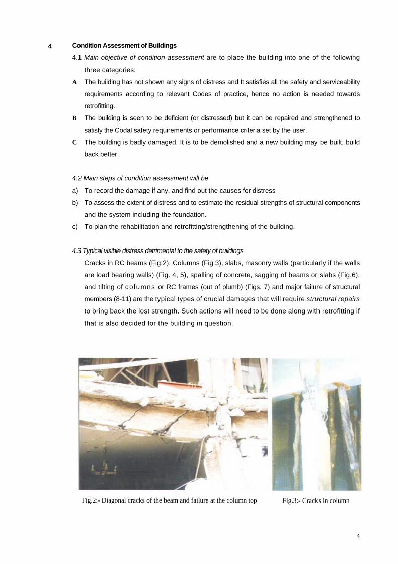
4.3 Typical visible distress detrimental to the safety of buildings
Cracks in RC beams (Fig.2), Columns (Fig 3), slabs, masonry walls (particularly if the walls
are load bearing walls) (Fig. 4, 5), spalling of concrete, sagging of beams or slabs (Fig.6),
and tilting of co lumns or RC frames (out of plumb) (Figs. 7) and major failure of structural
members (8-11) are the typical types of crucial damages that will require structural repairs
to bring back the lost strength. Such actions will need to be done along with retrofitting if
that is also decided for the building in question.
Fig.2:- Diagonal cracks of the beam and failure at the column top Fig.3:- Cracks in column
4

Fig.4:- Cracks in masonry wall Fig.5:- Cracks in good quality brick wall
Fig.6:- Failure of a portion of building (at expansion joint)
Fig.7:- Failure in column-beam joint (lack of stirrups)
Fig.8:- Column failure (absence of tiers, buckling of longitudinal
bars)
Fig.9:- Column top failure (bad joint detail)
4
.
5

Fig.10:- Corrosion in RC beam Fig.11:- Corrosion in the RC Column
Fig.12:- Corrosion in the RC slab (lack of control on the cover)
4.4 Main causes of such distress in buildings
Either one or more of the factors listed below may cause distress in buildings (Figs.2-12):
• Deficiencies in design
• Poor detailing of reinforcement in RC structural members and joints
• Poor quality of construction
• Corrosion of reinforcement due to aggressive environment.
• Inadequacies in the structural system to resist lateral forces due to natural hazards like cyclones
and earthquakes.
• Settlement or differential settlement of foundation
• Extreme and unforeseen loading.
6

5 Methodology of Condition Assessment
Condition assessment and evaluation is generally carried out in two levels:
(i) Preliminary and
(ii) detailed.
If we get adequate information to assess the safety of the building at the preliminary
investigation level, detailed investigation, which involves considerable cost and time, may not be
recommended.
5.1 Rapid (Visual) Investigation
There are mainly three components and steps:
• Collection of information and details about the building design, construction, utilization, and
maintenance in the past
• Visual inspection of condition at site and recording details of distress
• Evaluation of safety against the provisions in building codes or specified performance
criteria
5.2 Information needed for Rapid investigation
One needs a complete record of building design details and drawings, architectural details,
construction details and drawings including the specifications of materials used, geotechnical details
of the area and foundation particulars, details of any repair or retrofitting done from the time of
construction, details of usage of the building including the loads. Some nondestructive testing may
be required to check the strength of concrete masonry etc.
If the above information is not available, detailed investigations have to be conducted.
5.3 Details in visual Investigation
The main purpose of visual investigation is to observe and note down all the items of distress or
design deficiency and their locations, supported by sketches and drawings. The visual inspection
includes:
• Verification of the accuracy of the original drawings or determination of basic building
information, if no drawings are available.
• Identification of major alterations not shown on the original construction documents.
• 1dentification of visible structural damage, such as concrete cracking or spa1ling, and observations
on quality of construction
• Identification of potential non-structural falling hazards, including ceilings, partitions, curtain
Walls, parapets, fixtures, and other non-structural building elements.
• Observations on the condition of soil and the foundation
• Documentation of existing conditions with photographs at key locations.
Details about any deviations observed at the site from the original drawings have also to be
recorded.
Based on the data collected about the details of the building, visual observation of
7

damage/distress in different structural components and the system, structural engineers experts
can categorize the type and severity of damage and make judgments about further course of action.
Rapid assessment of safety of buildings becomes necessary in the aftermath of natural disasters like
earthquakes to take decisions about possible evacuation of unsafe buildings to save lives.
5.4 Observation of settlement or
differential settlement of buildings
Ground failures due to the following causes
may be observed:
• Liquefaction of soil (under moderate
to severe earthquakes)
• Landsliding, under monsoon rain or
earthquakes
• Surface fault rupture under the building
(remote possibility)
Some types of damage to the buildings Fig.13:- Damage of building due to ground failure
because of ground failures may be seen in Figs. 13 and 14.
Fig.14:- Diagrammatic explanation of diagonal tension crack due to differential settlement
6 Detailed Investigations
6.1 Need and actions
When the construction drawings about the building giving the layout and the structural details of
the system (including the specifications of materials used) and its foundation are not available,
detailed investigations have to be conducted about the total structural system besides of course the
details on type, location, and severity of damage or distress in various members and the system.
Measurements may have to be made on the existing building to note the dimensions of the
structural elements. Properties of structural materials, namely, concrete, steel
reinforcement and masonry, in the representative structural members, will be necessary by
conducting Non-Destructive Testing (NDT) in the field and by carrying out laboratory
8

investigations on samples collected from the field. Details of soil profile and its characterization
have to be obtained by collecting data or by conducting necessary geotechnical investigations.
These details are necessary for analyzing/evaluating the safety of the building and to
recommend retrofitting/strengthening measures.
6.2 Tests for assessment of in-situ quality of reinforced concrete
After identification of weak zones in a structure, detailed assessment of the in-situ quality of the
material is to be done. A number of tests have been developed and standardized for different
properties of concrete. Suitable tests are to be selected based on the aims of testing. A list of
various available tests is given below: Sl. No. Property under investigation Test Equipment type
1 Cores Mechanical
2 Pull-out Mechanical
3 Pull-off Mechanical
4 Break-off Mechanical
5 Internal fracture Mechanical
6 ESCOT Mechanical
7 Penetration resistance Mechanical
8 Maturity Chemical/Electrical
9
Concrete Strength
Temperature -matched curing Electrical/electronic
10 Surface hardness Mechanical
11 Ultrasonic pulse velocity Electronic
12 Radiography Radioactive
13 Radiometry Radioactive
14 Neutron absorption Radioactive
15 Relative humidity Chemical/electronic
16 Permeability Hydraulic
17 Absorption Hydraulic
18 Petrography Microscopic
19 Sulphate content Chemical
20 Expansion Mechanical
21 Air content Microscopic
22 Cement type and content Chemical/Microscopic
23
Concrete quality, durability and
deterioration
Abrasion resistance Mechanical
24 Half-cell potential Electrical
25 Resistivity Electrical
26 Cover depth Electromagnetic
27 Carbonation depth Chemical/Microscopic
28
Corrosion of embedded steel
Chloride concentration Chemical/Electrical
9
6.3 Tests for concrete strength
Concrete strength is the most important parameter in assessing the safety of a structure against
loading. Due to lack of construction supervision, sometimes, very low strength concrete may be
encountered in existing structures. Such locations are to be identified and suitable remedial
measures to be taken. The testing methods for concrete strength vary from very indirect surface
hardness test to the direct testing of concrete strength by removing cores.
Non-destructive tests These tests are based on indirect measurement of concrete strength through measurement of
surface hardness and dynamic modulus of elasticity. Calibration curves relating these properties with
the strength of concrete are available. For surface hardness rebound of an impact from the concrete
surface is measured.
The most commonly adopted NDT methods for assessment of strength of concrete and their
principles are given in the following:
Table 1: NDT methods and principles
Rebound
Hammer
Spring-driven mass strikes surface of concrete and rebound distance is
given in R-values. Surface hardness is measured and strength estimated
from calibration curves, keeping in mind the limitations.
Ultrasonic
Pulse Velocity
It operates on principle that stress wave propagation velocity is affected
by quality of concrete. Pulse waves are induced in materials and the time of
arrival measured at the receiving surface with a receiver. Ultrasonic pulse
velocity is influenced by elastic modulus and strength of concrete.
Penetration
resistance
Probes are gun-driven into concrete, depth of penetration converted to
estimates of concrete strength by using calibration curves
Pull-off
testing
Circular steel probe is bonded to concrete. Tensile force is applied using portable
mechanical system until concrete fails. Compressive strength can be estimated
using calibration charts
Core testing Drilled cylindrical core is removed from structure, tests may be performed on
core to determine compressive and tensile strength, torsional properties,
static modulus of elasticity, etc.
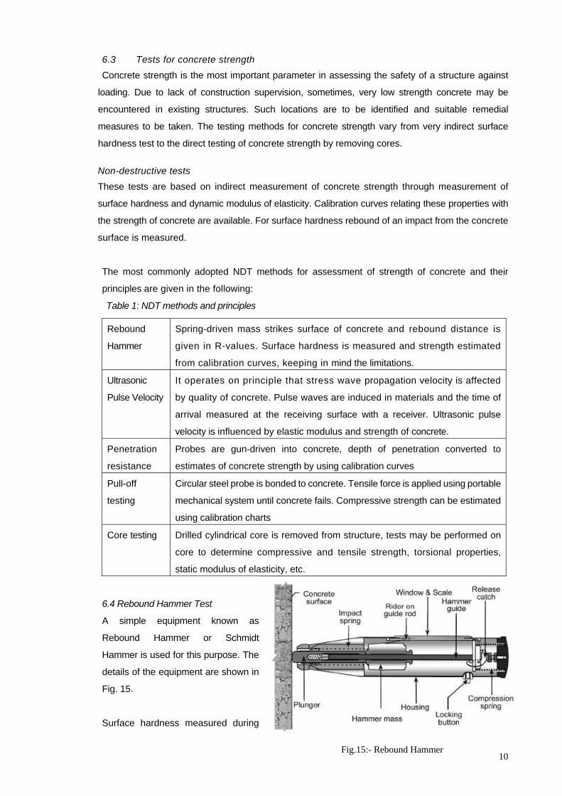
6.4 Rebound Hammer Test
A simple equipment known as
Rebound Hammer or Schmidt
Hammer is used for this purpose. The
details of the equipment are shown in
Fig. 15.
Surface hardness measured during
10Fig.15:- Rebound Hammer
the test give an idea about the soundness and quality of cover concrete. Locations having very
low rebound numbers indicate weak surface concrete and may be affected by corrosion. The
quality of concrete may be interpreted as shown in the Table 2.
Table 2: Average Rebound number and quality of concrete
Average Rebound Number Quality of Concrete
>40 Very good hard layer
30 to 40 Good layer
20 to 30 Fair
< 20 Poor concrete 0 Delaminated
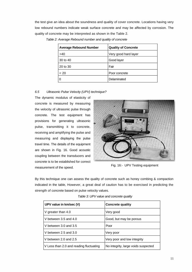
6.5 Ultrasonic Pulse Velocity (UPV) technique?
Fig. 16:- UPV Testing equipment
The dynamic modulus of elasticity of
concrete is measured by measuring
the velocity of ultrasonic pulse through
concrete. The test equipment has
provisions for generating ultrasonic
pulse, transmitting it to concrete,
receiving and amplifying the pulse and
measuring and displaying the pulse
travel time. The details of the equipment
are shown in Fig. 16. Good acoustic
coupling between the transducers and
concrete is to be established for correct
measurement of the speed.
By this technique one can assess the quality of concrete such as honey combing & compaction
indicated in the table, However, a great deal of caution has to be exercised in predicting the
strength of concrete based on pulse velocity values.
Table 3: UPV value and concrete quality
UPV value in km/sec (V) Concrete quality
V greater than 4.0 Very good
V between 3.5 and 4.0 Good, but may be porous
V between 3.0 and 3.5 Poor
V between 2.5 and 3.0 Very poor
V between 2.0 and 2.5 Very poor and low integrity
V Less than 2.0 and reading fluctuating No integrity, large voids suspected
11

6.6 Core tests
The core test provides the visual inspection of the interior of the concrete and direct measurement of
the compressive strength. Other physical properties, such as, density, water absorption, indirect
tensile strength and expansion due to alkali-aggregate reaction can also be measured. After
strength testing, these can be used as samples for chemical analysis. The procedure has been
standardized by BS, ASTM and ACI codes.
In core testing, the determination of core size and location is a crucial factor. The test should be taken
at points where minimum strength and maximum stress are likely to coincide. But, at the same time,
the core cutting causes some damage to the member and may impair the future performance of the
member. Therefore, in slender members, the core should be taken away from the critical section.
For compression testing, the diameter of the core should be at least three times the nominal
maximum aggregate size. The accuracy of the test increases with the ratio of core diameter to the
aggregate size. The generally recommended length to diameter ratio of the cores is between 1 to 2.
The core samples can be used for determination of unit weight, estimation of voids, and chemical
analysis, a graphic analysis and analysis. Broken samples from the cores can be used to
determine the pH value and the chloride content in the sample. These tests on cores and core
samples will also provide information that can be used to assess the state of corrosion of reinforcing
steel.
7. Partially destructive tests
These are surface zone tests, which require access to one exposed concrete face and cause some
localized damage. This damage is sufficiently small to cause no loss in structural performance. The strength
of concrete is estimated with the help of correlation charts, which are sensitive to lesser number of
parameters compared to the surface hardness and ultrasonic pulse velocity tests. Hence reliability of these
tests is higher. The advantage compared to core test is that these are faster and less disruptive and
damaging. Different tests in this category are based on penetration resistance, pull-out pull-off and break-off.
7.1 Penetration Resistance
In penetration resistance testing, a
specially designed bolt is fired into
concrete with the help of a
standardized explosive cartridge.
The equipment and testing
procedure have been standardized
by ASTM C803. A consistent
correlation of the depth of the
penetration with the strength of Fig. 17:- Penetration resistance test
12
concrete has been found. The details of failure process of concrete under penetration have been
shown in Fig. 17.
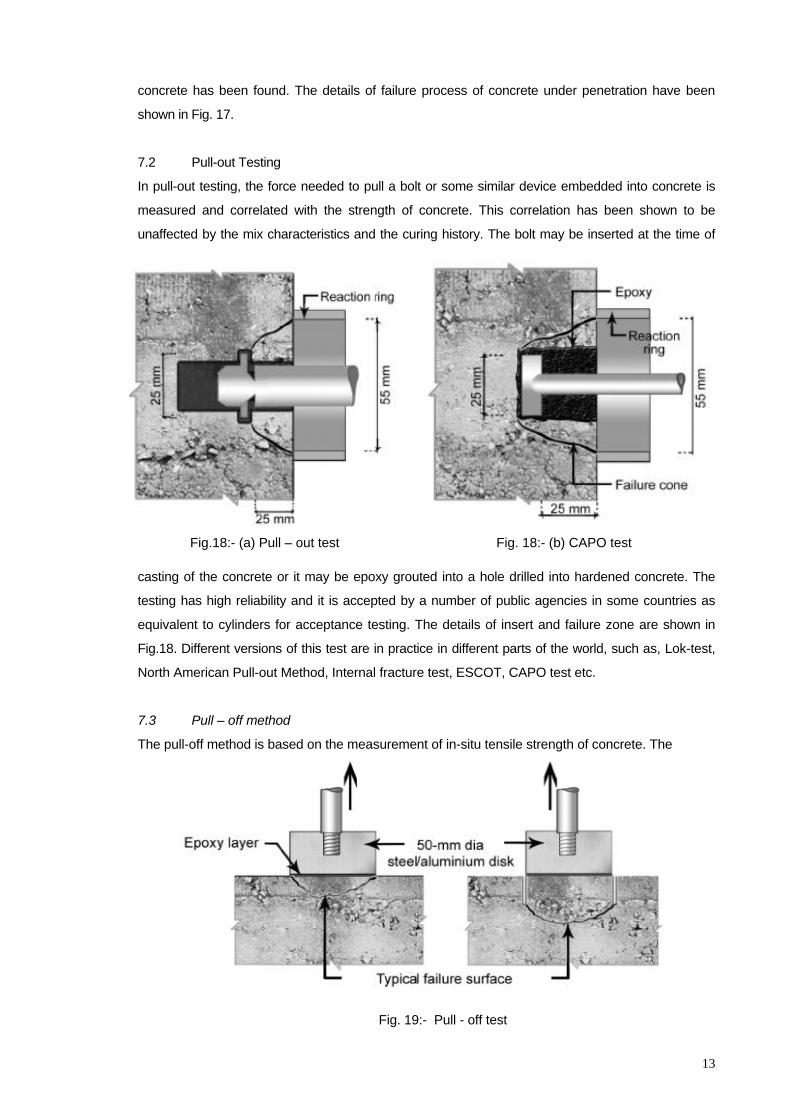
7.2 Pull-out Testing
In pull-out testing, the force needed to pull a bolt or some similar device embedded into concrete is
measured and correlated with the strength of concrete. This correlation has been shown to be
unaffected by the mix characteristics and the curing history. The bolt may be inserted at the time of
Fig. 18:- (b) CAPO test Fig.18:- (a) Pull – out test
casting of the concrete or it may be epoxy grouted into a hole drilled into hardened concrete. The
testing has high reliability and it is accepted by a number of public agencies in some countries as
equivalent to cylinders for acceptance testing. The details of insert and failure zone are shown in
Fig.18. Different versions of this test are in practice in different parts of the world, such as, Lok-test,
North American Pull-out Method, Internal fracture test, ESCOT, CAPO test etc.
7.3 Pull – off method
The pull-off method is based on the measurement of in-situ tensile strength of concrete. The
Fig. 19:- Pull - off test
13
compressive strength of concrete is well known to be related with the tensile strength. Another
application of the test is in testing of the bond between original and new concrete in repairs and
strengthening. The details of the test are shown in Fig.19. Two versions of the test are possible. In first
case a metallic disk is glued directly to the surface of concrete and pulled off to measure the force
necessary to pull a piece of concrete away from the surface. In the second case partial coring is done
with a standard diameter of 75mm and the above procedure is repeated by gluing the disk at the top of
the partial core. For assessing the bonding strength of the repairs with the original concrete, the depth
of the partial coring should be below the surface of the original concrete.
7.4 Interpretation about corrosion based on chemical analysis o f concre te?
The following Table gives some tips for interpretation about corrosion:
Table 4: Interpretation of test results on corrosion
Test Results from Chemical Analysis Interpretation about
Corrosion
High pH value( > 11.5) and very low chloride content No corrosion
High pH value and high chloride content greater than 0.4% - 0.6% by
weight of cement
Corrosion prone
Low pH value and high chloride content greater than 0.4% - 0.6% by
weight of cement
Highly corrosion prone
7.5 Location of steel reinforcement in RC structures by nondestructive tests
It is possible to locate steel reinforcement in concrete and to measure the size and concrete/masonry
cover by using Cover meters/ Pachometers, which work on the principle that steel affects e magnetic
field of the probe. Alternately, X-ray testing can be used to determine the location and quantity of steel
reinforcement.
7.6 Samples of steel reinforcement for determining the strength and other properties?
Samples of steel reinforcement may be taken from the structural members to determine their
strength, physical and chemical properties. The removed reinforcing steel has to be replaced as
required by designer' Sample specimens have to be taken from locations of minimum stress in the
reinforcement.
7.7 Corrosion of reinforcement in RC structures?
Corrosion of reinforcement in concrete structures is a complex electrochemical process. Migration
of moisture and aggressive chemicals through the porous cover concrete would cause corrosion of
steel reinforcement. The parameters or factors that influence corrosion are:
• cover thickness
• quality of concrete in the cover region, especially its permeability and diffusivity
• environmental conditions
14
• pH value and chloride level in concrete, and
• presence of cracks
8 Soil profiles at the site
Soil profiles may be broadly categorized as:
• Rocky
• Very dense soil and soft rock
• Stiff soil
• Soft soil
This categorization may be based on average soil properties of shear wave velocity, standard penetration
number, and undrained shear strength [for simple qualification Ref IS:1893 (Part 1) 2002 for preliminary
liquefaction potential of site refer cl…..]
9 Concluding Remarks
The importance and need for condition assessment and evaluation of safety of existing buildings and
foundations in disaster prone areas have been highlighted in this guideline. Safety evaluation forms the basis
for designing and carrying out retrofitting/strengthening of buildings to satisfy the safety and performance
standards as per the extant building codes. An overview of the procedures and different investigations
including tests involved in condition assessment and evaluation of safety is presented in a simple. It can be
seen that detailed visual inspection and Non Destructive Testing (NDT) plays an important role in condition
assessment of existing buildings. It may be emphasized here that a great deal of expertise is required for
interpretation of field observations and test results to make a proper assessment of the condition as well as
for analyzing and evaluating safety.
10 Acknowledgement
The information contained in this guide is largely extracted from the book ‘Condition Assessment of
Buildings in Disaster Prone Areas’ authored by TVSR Appa Rao and R.K.Bhandari and published by
Centre for Disaster Mitigation and Management, VIT University, Vellore, Tamil Nadu, India, 2007.
Assistance has also been taken from Chapter 13 seismic vulnerability assessment of existing buildings by
Y. Singh & D.K.Paul in lecture notes for National Programme for Capacity Building of Engineers in
Earthquake Risk Management (NPCBEERM), Dec 2006. 11 References
Detailed information about some of test for condition assessment may be obtained from the following
references:-
1. J.H. Bungey, 1989, The Testing of Concrete in Structures, Surrey University Press.
2. ACI Committee 437, 1991, Strength Evaluation of Existing Concrete Buildings, American Concrete
15
Institute.
3. IS 13311 (Part 1): 1992, Non-Destructive Testing of Concrete – Methods of Test, Part – 1, Ultra
Sound Pulse Velocity, Bureau of India Standards.
4. IS 13311 (Part 2): 1992, Non-Destructive Testing of Concrete – Methods of Test, Part – 2,
Rebound Hammer, Bureau of India Standards.
5. Hand Book on Non-Destructive Testing of Concrete, Second Edition, Edited by V.M. Malhotra and
N.J.Carino, CRC Press LLC, 2004.
6. Non-Destructive Testing of Concrete Structures, Proceedings of the INDO-US Workshop on
Non-Destructive Testing, Indian Concrete Institute, Roorkee, 17-18 December, 1996
7. Non-Destructive Testing in Civil Engineering Special Issue, Materials and Structures 38,
November 2005.
8. Guide for Evaluation of Concrete Structures Prior to Rehabilitation (ACI 364. 1R-94(99)), By ACI
Committee 364, Rehabilitation.
9. Formulation of Guidelines for Assessment of Strength and Performance of Existing Buildings and
Recommendations on Retrofitting Schemes to Ensure resistance to Earthquake, Report
No.SSP05441, SERC, Chennai, September 2002.
10. CPWD Handbook on Repair and Rehabilitation of RCC Structures, Central Public Works
Department (CPWD), Government of India, New Delhi, 2002.
Prepared By: Professor Anand S. Arya and Ankush Agarwal
G o I – U N D P , D i s a s t e r R i s k M a n a g e m e n t P r o g r a m m e E-mail:- [email protected]; [email protected]
NATIONAL DISASTER MANAGEMENT DIVISION M I N I S T R Y O F H O M E A F F A I R S , N O R T H B L O C K , N E W D E L H I
Tel:91-11-23093178; Tele/fax: 23094019, Email :ndmindia@nic. in;Websi te :www.ndmindia.n ic . in
16