condensed intro to tesla transformers by eric
TRANSCRIPT
CONDENSED INTRO TO
TESLA TRANSFORMERS
ERIC DOLLJI.RD
DISCLADmR:
This materia� was written ear�y in the project and is in need of e:tensive revision. Pages 1-16 res�t from experiment� investigations and theoretica� considera-. tions whi�e at my �ab in the Marconi Wire�ess Bui�ding (R.C.A.), at Bo�inas, Ca�ifornia, from 1980-1981. Pages 22-25 are taken from reference (2) and adapted for re�ation to Tes�a Coi� waves. Pages 25-31 are taken from reference (3) and serve as an i��ustration of how the Tes�a Magnifying Transmdtter can e:tract energy from the Earth's resonant e�ectric fie�d.
Eric P. Do��ard. March 22, 1986
p.o. Box 220 * Bayside, California * 95524 USA
THE TESLA TRANSFORMER
© 11 e6 E,f� i)OU-ATl.."l;)
1
At the turn of the.century Tesla was in the process of devis ing
a means of wireles s power transmission. The transmis s ion involved
the generation of long,itudinal ether waves. Whether Tesla accomplis hed
this is not known, but the idea was cons idered by other notables *
s uch as Kelvin and Maxwell. Kelvin cons idered it poss ible to
generate "longitudinal \t?aves in the luminiferous ether" thru the
phenomena of dis placement current (capacity current aD/at). He goes
on to indicate his feeling that these waves must be faster than
light, as the longitudinal waves in a s teel rod move with much
greater velocity t han the trans vers e waves. Tes la claims that the
waves from his trans former propagate:.at. 'tr/2 the veloci.ty of �ight.
It is interesting to note: that.:-the- veloc:;i.ty:measured .'-On.·:.the .. ·�e.sla
coiL is . .a1:so. "fr'!2. greater than·the·. vel.oc±ty "of:: light�'but�this ".
does. appear to be a phase velocity rather than a. group velocity.
Inhiswritings·Tesla.indicates s ome seemingly imposs ible
phenomena surroundthe e�nations from the s pherical terminal
capacity, and I have determined thes e to be true by experiment.
One is that the power gradient (poynting vector) is in the s ame
axis as the dielectric flux gradient. The other is the slow forma-
tion of a conductive area surrounding the s phere that is not ionic
in nature (in other words is not a s park or glow discharge) .
Contrary to popular relief, the Tes la trans former is not a
WSee reference 6.
2
steady state device but is a magnifier of transient phenomena.
Also it does not behave like a L. c. network nor a transmission
line, but more like a unique type of wave guide. If all parts
of the system are designed properly the EMF and hence dielectric
flux jumps from zero to an enormous value a�ost instantaneously,
thereby producing an a�ost inconceivable displacement current
into space. The transformer is then basically a device for rapidly
discharging the capacitor bank nearly instant� into free space,
producing an enormous dielectric shock wave similar to a sonic boom.
Because the dissipation of the transformer is for all practical
purposes negligible, the energy k eeps increasing at a linear rate
per cycle of oscillation, thereby accumulating a gigantic quantity
of electrical energy. (A -form of laser action may be possible. )
In order for the transformer to resonate with the planet the
energy storage in the active region that grows around the sphere
terminal must equal the conjugate energy storage of the earth,
a stiff requirement.
It is interesting to note that dielectric -breakdown in this
active region grow into a log periodic form based on X2-X=1 as the
log base. This will be recognised as the trancendental PHI or
the Golden Ratio. In glow discharges the ions of metallic elements
form stable spheres of diameter inverse to the atomic weight of
the element involved.
The transformer's principals of operation are as follows:
The first requirement is the sudden collapse of an energy field
thereby producing a sudden impulse of energy, second is the
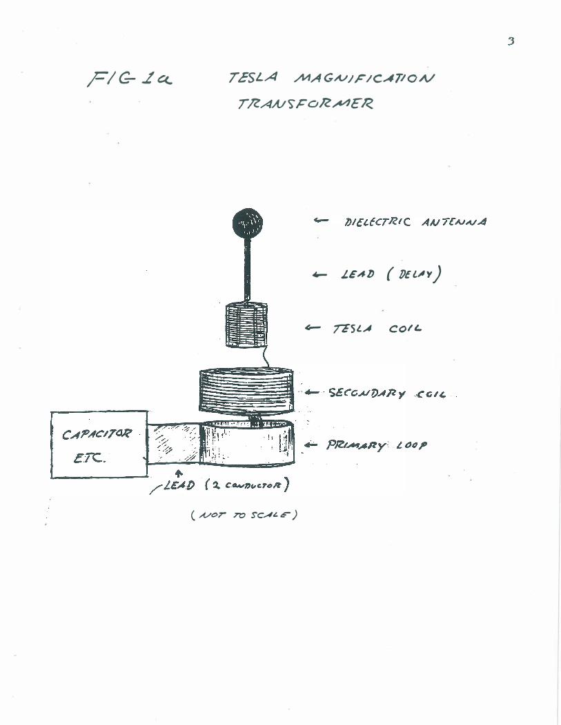
PI G- .L C<. TESLA .,AIIAGA.//F/CATION
T /ZAN$" ,c oR.A4E R
..... J.£Ab (lJEl;lY)
� 7&5 I.. A COIL.
(A/or 7"0 SC.A� r )
4
----.....---�� ..... -----
1 Ii R€SOAJANT COA./STANr
C,CJE�E"NT
rESLA
RES OAJAA./7 COA./STAAIT 'POTcA.l7AI..
c
-.
" /I CoIL
?RI
IA7>,,,. r E call_
� . " c;rEINAcT'Z: CoIL
e· L eli -
tI't
TE� AUT
t�o
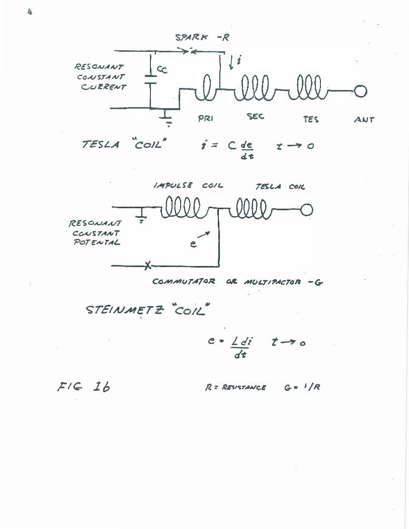
transforming properties of the odd harmonic ordered single wire
delay line (coil) which allow for the production of enormous
E. M.F. and M. M.F., and third, the dielectric phenomena surrounding
the free s pace capacity terminal.
1) The formation of the energy impulse involves the discharge
5
of a capacitor with the highest practical stored energy into an
impedance (inductive) of the lowest practical value, and the discharge
path is coupled to an energy supply through a negative resistance
device. This negative resistance is classically a spark discharge ,
but a superior plasma device needs to be developed to enhance
efficiency. Under optimal conditions the exponent of os cillation
amplitude will be positive over a s ustained period of time.
The net result of this system is the production of an extreme
impulse of M.M.F. of great d¢/dt. An alternate method is the
dis charge of an inductor of the highest practical stored energy
into a circuit of the lowerst practical admitta nce , thereby pro
ducing an enormous impulse of E.M.F. of great d�/dt.
2) The energy impulse generated by the aforementioned methods
is then coupled into a pair of single wire transmis sion s y s tems .
Through induction a s trong travelling wave is formed. Due to the
Lropedance transforming properties of the odd (A/4, 3�/4, etc) order
line, the E.M. F. of the wave is converted into lightning magnitudes ,
s till retaining the extreme d/dt of the initial discharge .
The capacitive discharge method of impulse generation is
Teslats faYorite, but Steinmetz s hows that inductive discharges will
also work.
6
The'capacitor contains the initial energy of the oscillating
system. The buss from the capacitors to ,the primary loop should
have a negligible transient impedance. The capacitors should be
of the bolt on vacuum type, however, the unique dielectric properties
of water might be of advantage as capacitor plates. The capacitors
must be in symmetrical arrangement with the primary coil. The
primary must be of one turn only and exhibit the lowest practical
impulse reactance S(P) P=di/dt. Tesla indicates the proper length
of the prLmary conductor to be �/2=Kn, where n is a harmonic number
convenient for the size of the unit and K is unspeCified. Also
unspecified-is if this value is free osee disconnected from the
capacitors or is LC dependent.
The transmission network consists of two X/4 single wire transmission
.systems of negligible radiation loss. The first of these is called
.::the secondary coil. The next is cal�ed the "extra coil" by Tesla, but
_',:.henceforth w:i��-be':,ca�led.the: "�esla:CCJ±�·,� This ,network. 0: ;'.'line
":is . typically,. absent' in: .. mast- uni.ts;', purport:inq. 'ta. be.-:Tes1a .trm:tsformers •.
The secondary coil, serves as a:. ma tch:ing ... ne'bt)rk, . between. the wave
generating primary' loop' and: the Tesla co:iL.· The magnetic coupl:ing
factor·�· between the PRI and SEC' coils is typically 20%.
Negligible magnetic coupling should exist between the secondary
and Tesla coils.
The function of-the secondary is three fold. The first is the
transforming of the primary M.M. F. pulse into an abrupt travelling
electric wave. Second, to provide a constant potential constant
current transformation for good voltage regulation at the output·
terminal of the Tesla coil, and third is to match the drive impedance
of the Tesla coil to the drive impedance of the earth. * (next page)
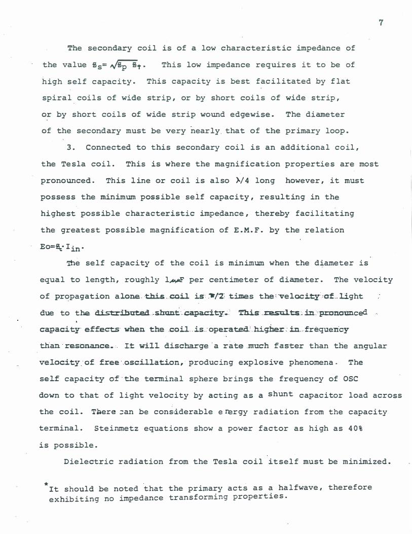
The secondary coil is of a low characteristic impedance of
the value Ss= �t. This low impedance requires it to be of
high s elf capacity. This capacity is best facilitated by flat
s piral coils of wide strip, or by short coils of wide s trip,
or by s hort coils of wide strip wound edgewise. The diameter
of the secondary must be very nearly. that of the primary loop.
3. C onnected to this secondary coil is an additional coil,
the Tesla coil. This is where the magnification properties are most
pronounced. This line or coil is also �/4 long however, it mus t
possess the minimum possible s elf capacity, resulting in the
highest possible characteristic impedance, thereby facilitating
the greates t poss ible magnification of E.M.F. by the relation
Eo=�· Iin.
The s elf capacity of the coil is minimum when the diameter is
7
equal to length, roughly l� per centimeter of diameter. The velocity
of propagation alone. ·this.coll is ,"l2;times the'·veloci.ty."of ... llght
due to thedistributed.;shunt-":(:apacity�. This: . .re.sul.ts.·�in:'�nolm.ced
capacity effects· whenthe coi..l . . is . operated; higher in. . . frequency
than resOnance • . I.t wil.l discharge a rate .much faster than the angular
velocity.·of free osc.i.llation, producing explosive phenomena. The
self capacity 0·£ the terminal sphere br ings the frequency of OSC
down to that of light velocity by acting as a shunt capacitor load across
the coil. Tbere ::an be cons ,iderable e n:rgy radiation from the capacity
terminal. Steinmetz equations show a power factor as high as 40%
is possible.
Dielectric radiation from the Tesla coil itself must be minimized.
*It s hould be noted that the primary acts as a halfwave, therefore
exhibiting no impedance trans forming properties .
8
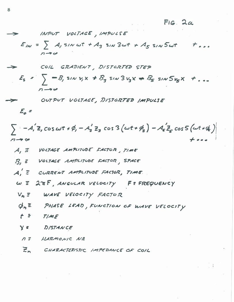
----=!>� I A/PvT VOl TAt: E J //11 Pv t, r c
£J/v = 2 A/ -SIN c...Jt + A3 �JAI 3w-t r AS S.lN 5' wT n�oII
� CoIL. C!ZA7JJE"N7 � l)/STanTG �re-P
Es.r 2 -� SIN 'J X + 83 SIAl '3 V3� .,. Os SIN5.,sx + . ••
n '--'eP
r _
�e; -
l". -.4:2, cos cuT � ¢, - � %:r Cos '3 ('-'f+ 9fr) - A�lS" Cos 5" (c..t;.�)1 n--'� +, •• 1
v" -=
t :-
n:
IvA"£ V£�O(!ITy FACToR.. 1'J./ArE' .lFAI) � F'vA/cTIOA/ c� IIvAVe- J/rlocITy TIME
f)lsTANce
+ I ,
, ,
.... ,
,
,
,
,
0 •
,
,
,
,
#.
,
,
" ,
, ,
,
- L.
l)/sTAUCE
,
, ,
,
- ,
,
T
. , , ,
. ,
I , , .
- ,
, T' I , .. ,..,
T
. , , ,
, , ,
, . ,
9
AI"!
, lis
.. £1' '3'::; '3),,/4'
IN lov'" O'l
10
This is achieved by concentric configura tion with the primary /
secondary system therby enclosing its dielectric flux.
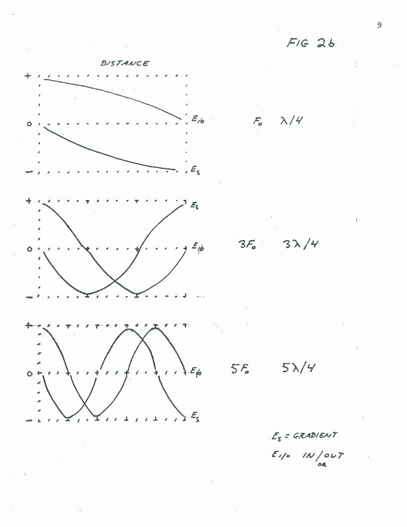
The potential gradient along L�e Tesla coil is approximately a
step function due to the phase d isplacement of the. input impulse ' s
harmonics, however, the velocity of the higher ordered overtones
become proportionate to frequency if the self capacity becomes
s ignificant, thereby distorting this gradient which assumes equal
velocity for all overtones.
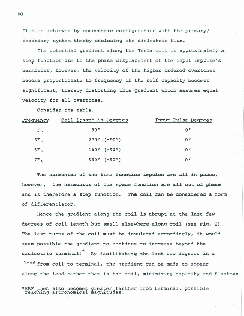
Consider the table.
Freguency Coil Length in Degrees Input Pulse Degrees
Fo 900 00
3Fo 2700 (-900) 00
5Fo 4500 (+900) 00
7F 0 6300 (-900) 00
The harmonics of the t�e function impulse are all in phase,
however, the har.monics of the space function are all out of phase
and is therefore a step func tion. The coil can be cons idered a form
of differentiator.
Hence the gradient along the coil is abrupt at the last few
degrees of coil length but small elsewhere along coil (see Fig. 2).
The last turns of the coil must be insulated accordingly , it would
seem possible the gradient to continue to increase beyond the
* dielectric terminal! By facilitating the last few de grees in a
lead from coil to terminal, the gradient can be made to appear
along the lead rather than in the coil, minimizing capacity and flashove:
*EMF then also becQmes greater f arther from terminal, possible reaching astronom�cal magnitudes.
problems. The dielectric radiation from this lead will be small
as it is Lmmersed in the sphere's flux. No data exists as to the
ratio of the size of the s phere and earth.
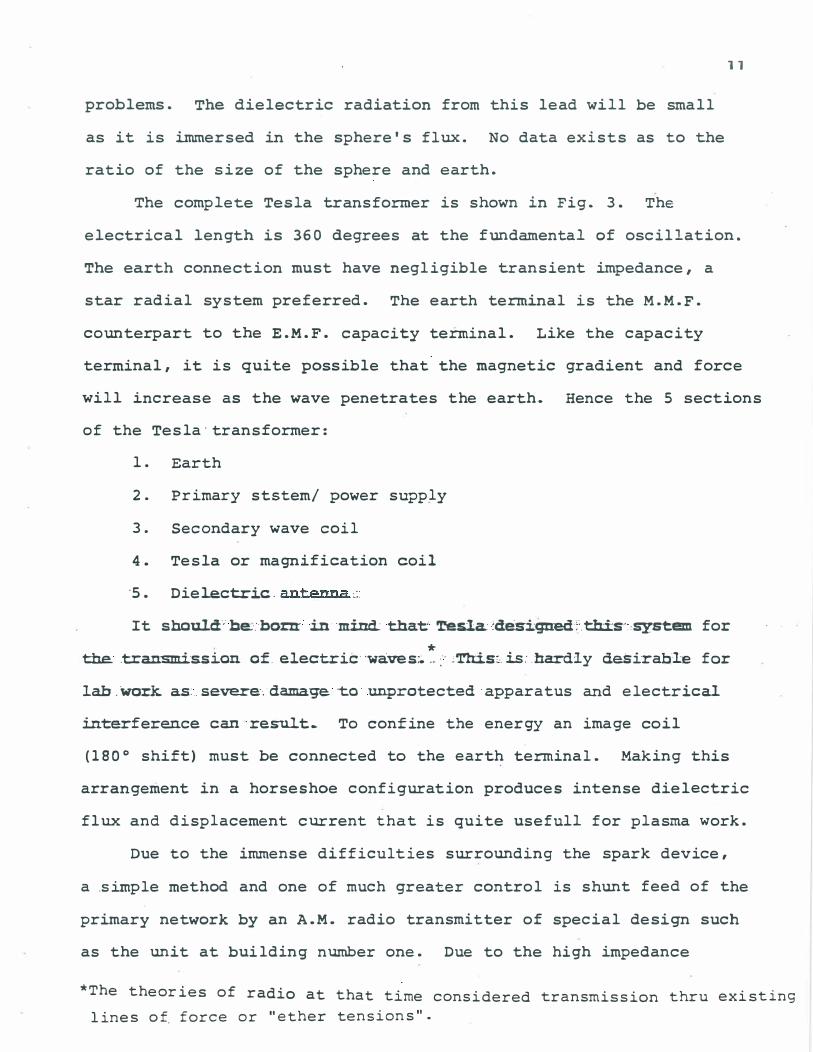
The complete Tes1a transformer is shown in Fig. 3. The
11
electrical length is 360 degrees at the fundamental of oscillation.
The earth connection must have negligible transient impedance, a
star radial system preferred. The earth terminal is the M.M.F.
counterpart to the E.M.F. capacity terminal. Like the capacity
terminal, it is quite possible that the m agnetic gradient and force
will increase as the wave penetrates the earth. Hence the 5 sections
of the Tes1a-transformer:
1. Earth
2. Primary ststem/ power supply
3. Secondary wave coil
4. Tes1a or magnification coil
'5. Diel.ectric. antenna �:
It should'be:.born:- in mind: that 'resla:des.iqned:�thi:s,:,system for
* the. .tran-smission of. electric·waves:;. .. :' :Th:;is:.:is: .hardly dasi'rable for
lab.Work as: .. severe'. damage to unprotected apparatus and electrical
interference can·re�t.. To confine the energy an image coil
(1800 shift) must be connected to the earth terminal. Making this
arrangement in a horseshoe configuration produces intense dielectric
flux and displacement current that is quite usefu1l for plasma work.
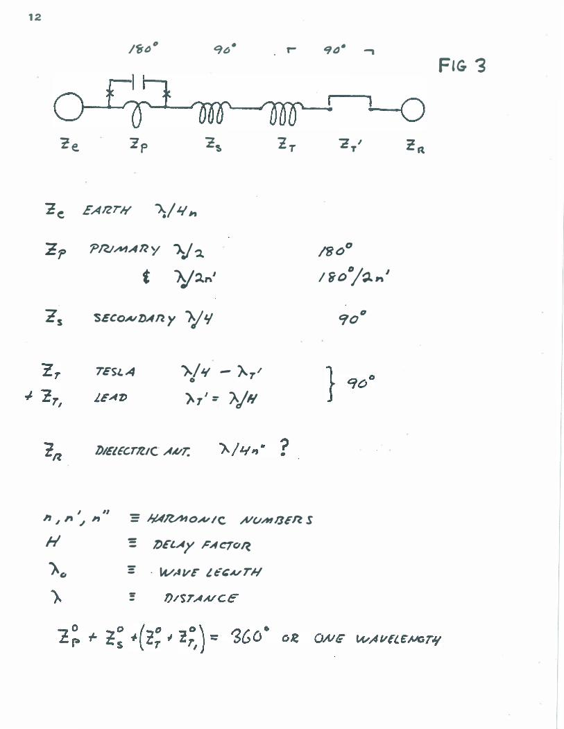
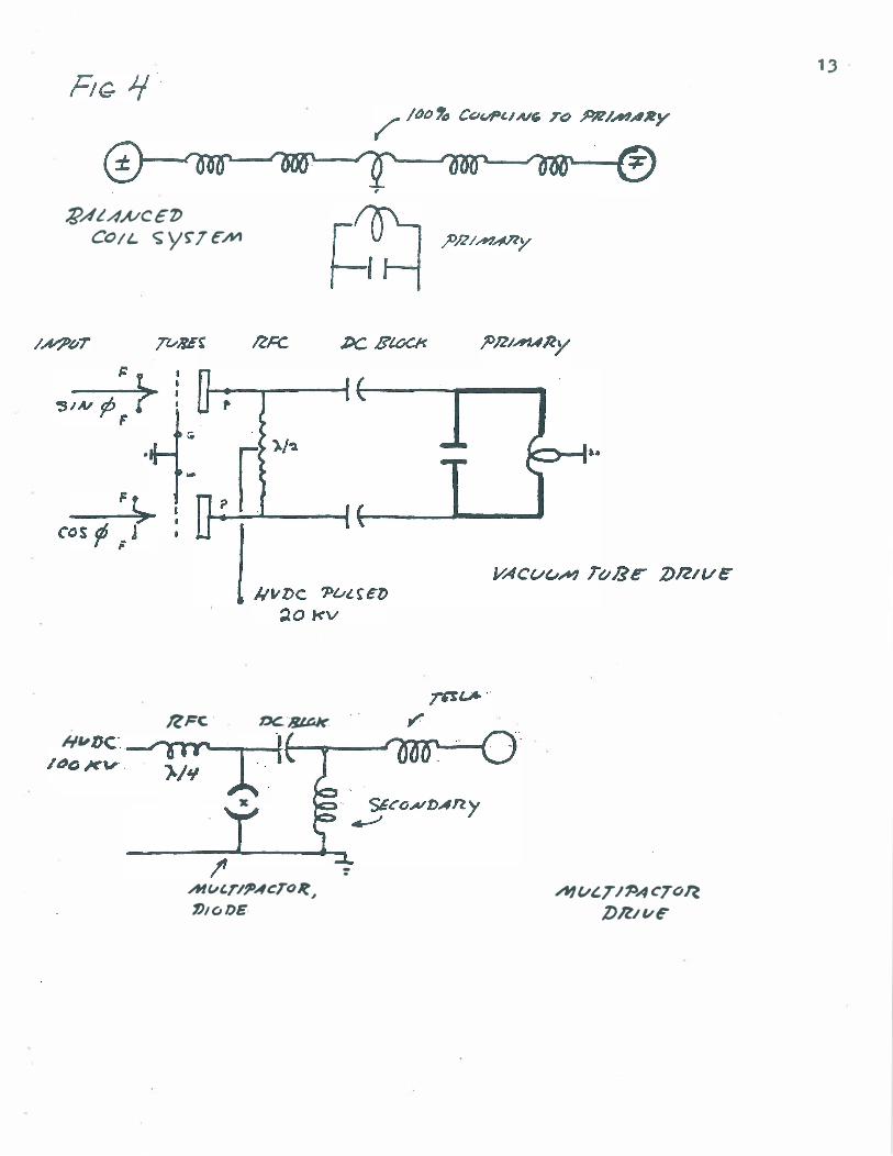
Due to the immense difficulties surrounding the spark device,
a simple method and one of much greater control is shunt feed of the
primary network by an A.M. radio transmitter of special design such
as the unit at building number one. Due to the high impedance
*The theories of radio at that time considered transmission thru existing
lines of. force or "ether tensions".
12
IfJ()" '96- r-
re, zp 2� 1T
�e EAlZr", 1.:/1./11
�p 'PnJAlfARy J...J� t )..j'J.,..1
-Zs SEcoNDAny ""/'1
7ESL4 )../1{ - Ar/ o
�TI::: "IN
/)/E/ EcrlllC AA/T.
I II " , ,. � I'J := JlAIlA10N/C A/t/AI/]£n s
1-1 = DElAy PAC1o�
)0 =- - k/AVF /.et:A/TN :: -
9(J- ..,
FIG j
L() "2 I
T 2rt
/800
I woo/�'" J
'1011
�AL4A/C€'/) COIL c;;yrTcM
.,
It Fe . DC.. '8LGk. hi" DC·· ---r�---'-O'l't�r"" ---' ...--f.t t-...,.._.-.Jt'/rx;r�-l /-.... . � .. - . T , . ' -OW " - , )./1/ A
x
I' Alv'r/?",cTo�1 1hoDE
-. AI vt.T I�A CT(iR
DR/vE"
13

14
offered by the primary resonator the �pedance effective of the
tubes must be high and therefore must operate at high anode
voltages. The electron emission however, must also be high, necessitatins
large cathodes and teIr.peratures. High anode S and large electron emissic
are usually of inverse relation in available vacuum tubes. Special
pulse modulator vacuum tubes must be used. Hydrogen thyratrons might
operate satisfactorally at low frequencies where the� 1 microsecond
deionization time will not hinder commutation. The most effective
device for shunt feed may be the multipactor tube due to its stong
negative resistance effects, but it is not clear if it will operate belo�
l�eOKC with much efficiency.
By the utilization of the aforementioned devices a much �proved
field is devloped at the transformer output with regard to stability.
This I have found desirable for the production of stable plasma
formations.
However, I have not noticed the "j amming together of electrons""
unless the spark method is used as the rate of ·rise of EMF is much
greater by the spark method. Perhaps the multipactor will operate
comparatively but strong impulses d o not seem possible with shunt
methods.
For stability of certain plasma effects AFC may be required.
(See Fig. 5) The image coil system exhibits strong discriminator
effects and thereby facilitates the formation of an error signal to
the V.C .O.
As to physical construction the primary should be sheet copper
of great conductor width and large loop area. Large surface is
required as the skin effect is total with impulses. Large width
also min�izes inductance allowing for larger capacitors and more

� � ,- -
1'i-JAS£ .. I/. C.O .. R.P. .. ?vwlll f)I(clZ , .,. AAf'P'- AAf7L
� �� 'r'iYAJC
ScoPf � !>vISE ... 1't/(.,� .. Pv"�
G�N .,. AIHP,- -. N/ Of)
1" T1f.IG-
rES LA
C, ;tel.
SEC., ' SEC ..
, ,. .6�C'7V "'�?Ac"V p/t<1?>6" � F1Z�;'�" L&.. _"-'· ____
�. ,
. ;:-1' �
� TO :?,t,Ust" :D'rcR'-''''ATon
: .
15
16
rapid discharge and hence high impulse strength. In opposition
to this required �nductive reduction is the need for a large area
due to the flashover and coupling requirements. Hence a balance
has to be established between the need for minimum inductance
for rapid discharge and for a large magnetic field, resulting
in large inductance. The formula for inductance (rationalized)
is L=area/width.
Tesla indicates that the copper weight of the secondary
must equal that of the primary for maximum efficiency. This
of . course goes along with:·.standard transformer theory but it must be
remembered that the depth .:of :pene.tration of waves into conductors
'. is microscopic forimpulses. This copper requirement must be modified
to equal surface area rather than weight. As to the use of water
for capacitor conductors Tesla gives no reason. It would seem that
this is done for the sake of simplicity and/or is a holdover from
the Leyden jar. (Remember he began this in 1890 ). However, water
has many curious dielectric properties that may be essential in
operation. By theory, for maximum discharge velocity the dielectric
must be a vacuum.
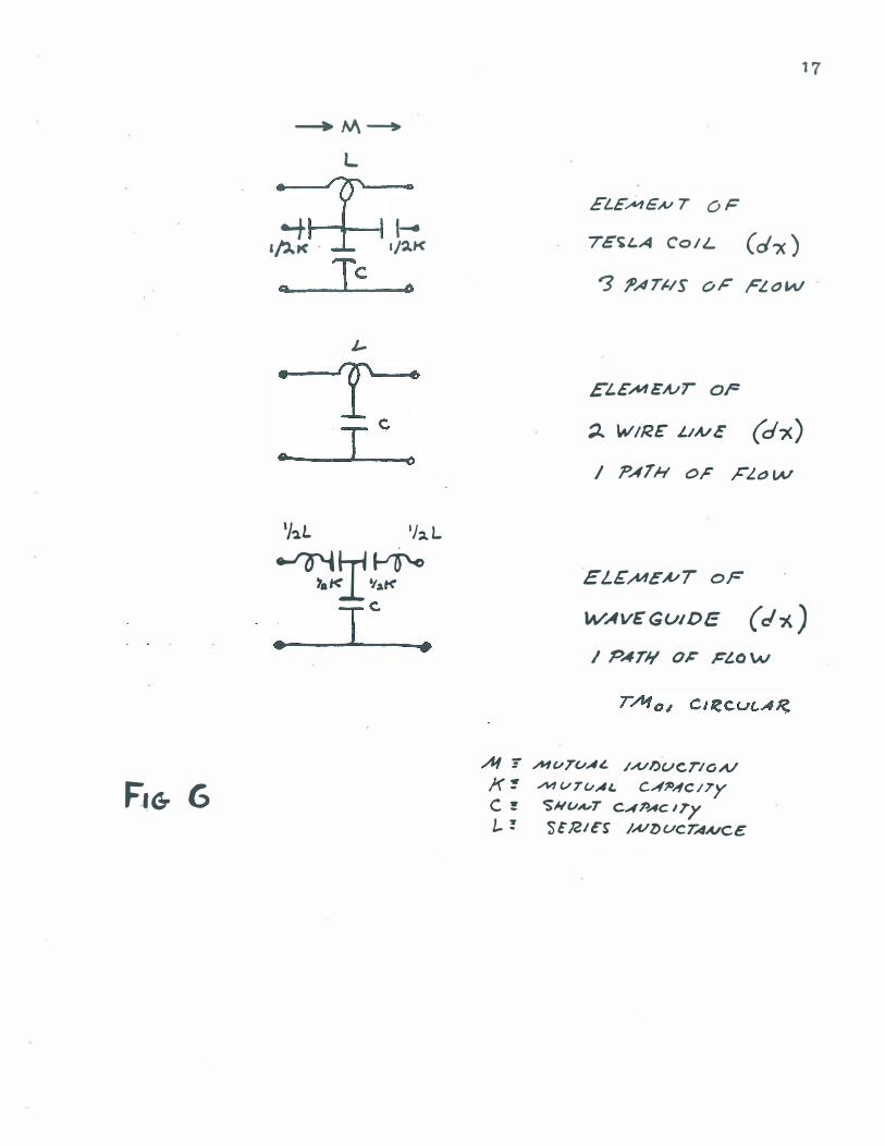
Analysis (See Fig. 6)
The oscillating coil differs from the transmission line on
account of turn to turn capacity and distributed mutual induction.
The presence of series capacity causes the coil to respond
as a capacitor network (with no inductive effect) towards abrupt
impulses and ang�lar velocities greater than the angular velocity
of free . oscillation.
---+M�
L
� t ..... lAw< '/"4K
0 Ie f)
J-•
Ie -6
I • ()
'J"l.L '/,.L
�1<1tr" • Ie
•
F,G- 6
17
EL£;N1€A/ 7 OF
7Et;.LA COIL (d�) '3 fJATJ./S oj:' FLOW
ELEM ENT OF
;l.. WIRE L.hVE (d-x) / PATH OF FLt:JW
EL£�EA/T of
WAvEGUIDE (cI'-h) I PAT)! OJ: Fl.O \AI
.At -= """�TvA£ /A/l)ucrIOA.l X � AI1VTvAL CA70,fCI7y C � 'SN�A"T CAPAC ITy 1.. ! St!Zle� /A/l.>ucrAUCe

18
The voltage distribution along the coil at the first instant
depends on the factor a= �g/cs. Cg= capacity to ground, Cs=
capacity from end to end • .
The greater a, th� greater the concentration of voltage
at the feed end of the coil. The max�um voltage per unit length
is equal to a t�es the voltage of uniform distribution. a is a
small fractional value with Tesla coils.
The greater the d/dt or � the greater the gradient of voltage.
If the impulse has a long tail the phenomena will be as
described but followed by a damped oscillation. (OSC)
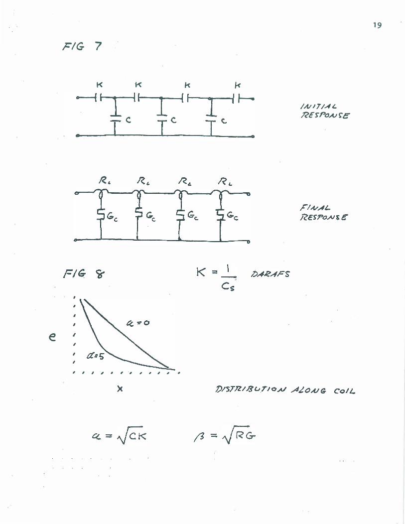
By impressing a sustained oscillation, and if the coil
.has a small dissipation const"ant u, the voltage will
continue to increase indefinately. Initially the coil acts as a
capacitor ladder network (See Fig. 7). The capacity elements a re
c har-ged to nearly twice the applied E.M.F. The effective
capacity being charged is C= �CgCs. Because this netwwork contains
" impedance elements of only one type the voltage distribution is
hyperbolic rather than periodic. If %=distance/total length and
e is voltage to ground at the particular distance,
e= Eo COSH a % . For Tesla coils this distribution should be as COSH a
linear as possible (small a).
As the distribution goes from initial to final the voltage
can be analyzed into a complex series of decremental waves at various
frequencies and wavelengths. This is accomplished by analyzing the
initial distribution (hyperbolic) into space harmonics with respect
to the final (DC) distribution. If a is considerable, no linear relatio
exists between frequency and wave length. (See Fig. 8)
When a n oscillating wave follows the initial impulse (as is the
e
�/G 7
K 1-< k
-ITTI
T C Ie. •
,
,
,
,
,
, ,
RI.
, , I , � , 'I I , , " "
19
k
I I J--. /AIITIA(" RE�poAJrc
I� •
20
case with the Tesla transformer) the alternate positive and negative
voltages cause continuous increase in voltage and energy. The effect
of the alternations is to increase the amplitude of the wave by twice
the applied voltage for each alternation. Example - oscillating
voltage is 1. 24 times applied voltage. (initial) At each cy cle
this is multiplied by twice Ea, causing E to ground to increase in steps
At second cycle E is 4.72, at third E is 7. 20 , etc. This effect is
reduced or suppressed by large u or �
The action of the spark gap has a multiplicative effect also.
Consider Steinmitz' analysis. "Continual or cumulative oscillations
involve an energy supply to the system. If the energy supply is less
than energy dissipation the e sc. do¥t1Ps as a trans ient with reduced
u. If the supply equals the dissipation the esc is continuous.
If supply is greater the esc is cumulative.
The esc represent energy and frequency transformation from
the L. F. or D.C. supply to theH .F. esc system. This transfer may
be brought about by the transient of energy readjustment resulting
from a change in circuit conditions, producing agairi a change in
circuit conditions and thereby an energy adjustment by transient,
etc., etc • . •
Recurrent oscillations tend to run into each other and form
continuous esc. When successive transients run in to each other
they tend to synch.
However, the formation of continuous esc is not the mere
overlap or running together of successive waves. The recurrent
OSC c'annot start until the preceding esc has died out I and sufficient
charge time has elapsed for next arc a'er of gap. With overlap no dead
period occurs during which normal or supply frequency is supplied.
Energy then must be supplied by a phase disolacement within arc
Is
L =
C --
k =
/V\=
L, --
C, --
K ::I I
M a I
FIG - 9-
L, M,
k,
c ,
dx
-I /?')vT"r,.,lA' /,A../T)Glc,A,/VCt- IN (#G'",vny)
L ?£R /...vc;....t
C rE"12 /;UCH
I< Pc� IAJCH
/V\ �B2 ,INCh'
'U --1 r � - L ;4 L.
21
G ] + -C
22
Dur� osci��ation, which gives a negative energy cyc�e or a reversed
hysteresis �oop. For continuous osci��ation then, a hysteresis
�oop nust be £ormed by the �ag o£ e££ect be£ore cause." (This is negative resistance or the £ormation rather than the dissipation o£
energy. ) "For the cWDU�at:l.ve osci��ation, the area o£ the loop must
depend on and increase with the stored vo�t amps o£ the osci��ating
system. II
Then
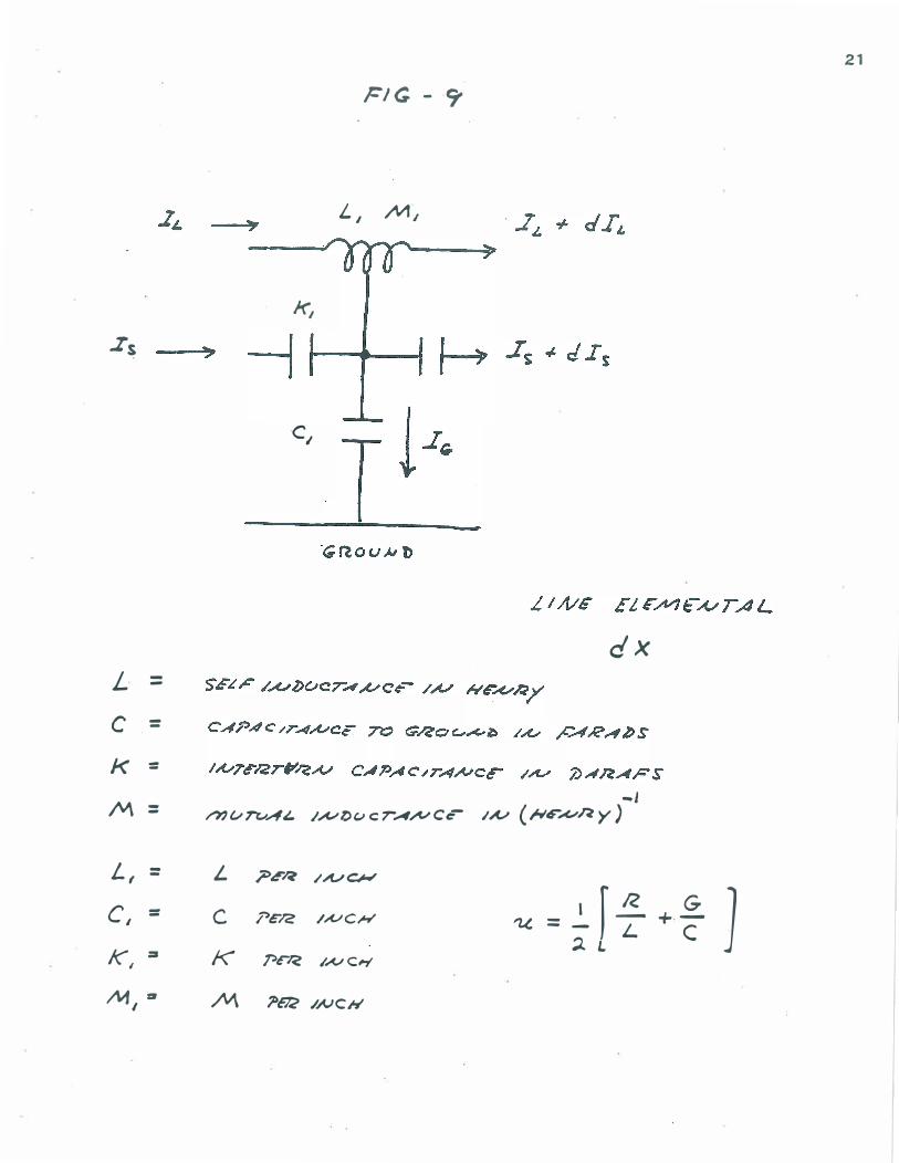
Mathematic ana�ysis (See Fig. 9) (See re£erence 2) e = E to ground es = E gradient (E/inch) By lCircho£f's Law
Let 7.s = a/ /a�
= space operator
Let '7t = a / = tae operator /d t:
= 0
Differentiation of (2)&) in time gives
"'Ys')'� IL -#- '71t?'� Is - "Ys"""'t J, : 0
( 23a )
( 23b) These, ( 23a ) & (23b) are independent of initia� and £inal distributions
of EMP'.
Equation (23b) must be expressed in one variab�eo In terms of
vo.ltage and current, the current density in capacity to grounc1 is
C per inch of coil times the rate of change of e to ground. g
( 26 )
R.�atiDg I aDd To�tage II
I in capacity between turns equa�s capacity per inch times s the time rate of vo�tage gradient.
I : S
"I ?'� ?'"t e K I
Re�atiDg I� and vo�tages
23
(28)
(29)
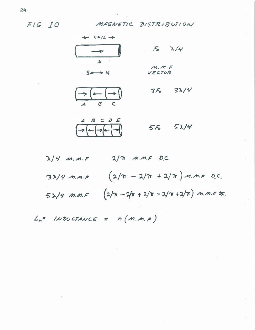
The re�ation between magnetizing current and I�
is comp�ex and
defies ana�ysis. ( See Fig. 10). For the fundamental distribution
(t wave ) the effeQtive inductance of the coi� is the space integra�
of the t cosine wave of current of H.M.F. and is equiva�ent to 2/ times the norma� total inductance. For the third harmonic, 3/4 cosine wave of current or H.M.F. the inductance of 1/3 of the coi�
opposes the remaining 1nductance resu�ting in diminishment of se�f
induction depending on the IDUtua� inductance of the bucking section to the rest of the coi�o The process progre •• es simi�ar�y for the
rest of the harmonic series (5F, 7F, 9F, etc. ) . This resul.ts in surge
impedance for each harmonic but effects tend to cance� for wave �ength.:>
Capacitance of the coi� behaves in a simi�ar fashion and may be
vo�tage dependent giving the coil vOltage gaiD under the proper
conditions. (Parametric amp�ification ) Denoting this residual inductance as l eakage inductance L, aDd
-2 1 the dimensions of 1 as the DlUtua� inductance M (Henry- ) , then
--
(30a)
(30b)
24
r/� 10
( s- 9 N
(�('--{-O A 13 c
AI '/ h', ,/til. F l/'b M . .;AI1.� D.C.
(')../� - 1./7r + ':J./1t ) /fI7./f'J.�
L,,= 1,A/7)f./CTANCc = n (hi."""".;: )
DC r •
25 (30b) give. the va�ue of ..,,� I". , whi�e (2)a) in'Yo�'Ye s ,.,..� I, •
If we differe�tiate the former with respect to x and the 1atter with
respect to t, substitution becomes possib�e.
()1) (31), (29) and (27) express in terms of vo�ts the three terms of (2)b).
Hence, the genera� equation:
This equation neg�ects �osses.
Ana1ysis of the interaction between the earth and various coi1s
is possib�e by the use of ve10city measure. This in genera� is a
comp1ex quantity consisting of rea� and imaginary parts.
By the re1ation we1� known:
(34)
where v is the ve�ocity of the wave. Then ve�ocityis the ratio of
time to space. Letting this ve�ocity be of unit �ue, time and space
2 2 f'mlctiona become equiya�ent, ''''s =?'t' • stei.Dmetz gives the fo�1ovi.ng bstructions for accomp�ishing this._
"Line constants are typica1�y given per unit �ength, as per
cent�etre" mi�e, 1 000 feet, etc.
The moet convenientvunit o� �ength, when dea�ing with transie�ts
in clistrubuted circuits, is the ve�ocity unit v.
Tbat is, choosing as unit �e�gth the distance of propagation in
unit time, or 3 times 1010 em/sec for transverse waves in air,' this
gives v = 1 and therefore LC = 1 = �
-1 C = L ;
26
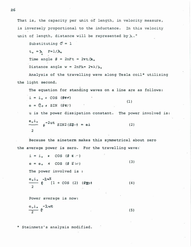
That is, the capacity per unit of length, in velocity measure,
is inverse�y proportional to the inductance. In this velocity
uni t of length, distance will be represented by A. "
Substituting 6= I
to =). F=l/Ao o Time angle � = 2nFt = 2�t/�o
Distance angle w = 2nF�= 2�A/�o
Analysis of the travelling wave along Tesla coil* utilizing
the light second. ,.
The equation for standing waves on a line are as follows:
i = io ¥ COS (e��)
e = eo Jt SIN (�:t�,.,,) (1)
u is the power disSipation constant. The power involved is:
(2) 2
Because the sineterrn makes this symmetrical about zero
the average power is zero. For the travelling wave:
i = io If COS (� t: ." )
e = eo � COs (� ;�v)
The power involved is :
eo io -l .. ,,-r - Eo [1 + COS (2) (�:l'..
2
Power average is now:
2
* Steinmetz's analysis modified.
(3)
(4)
(5)

27
Thus two waves exist, a.travelling steady power flow given by
( 5) and a standing wave given by (2) s uch a flow of power flows
along the different s ections of the Tesla trans former, consisting
of sections of different u. For instance the primary has very low
u due to the large s urfaces and the negative u of the arc, the secondary
has a higher u due to no arc, the Tes la coil has higher yet due to
the small conductor size of winding, and the d ielectric antenna
has a very high u due to radiation.
In the pr�mary the duration of oscillation is very great as u
is zero or negative. The duration of coil os cillation is shorter due
to their higher u, and by themselves their osc would dampen
quickly. Since all are connected together, all mus t dampen together.
It then follows that power must flow during transient from primary
to antenna, so as to have all sections dampen together.
Three conditions can occur in the general compound sys tem:
a) The power flow is uniform, that is , the power remains
cons tant in the direction of propagation.
b) The flow decreas es in the direction of propagation.
c) The flow of power increases in the direction of propagation.
This last cas e is of special interest in the Tes la trans former
as it increases the steepnes s of the wavefront, producing greater
displacement current.
If the flow of power increases along system, more power leaves
every line element than enters it; that is , the line element is
drained of its stored energy by the ?assage of the wave, and then
dies down with time at a faster rate than by its own diss ipation.
That is , not all the stored energy of the line elements supplies the
power dissipated in the line elements , but part of the energy leaves
the elements in increasing the flow of power along the line. The
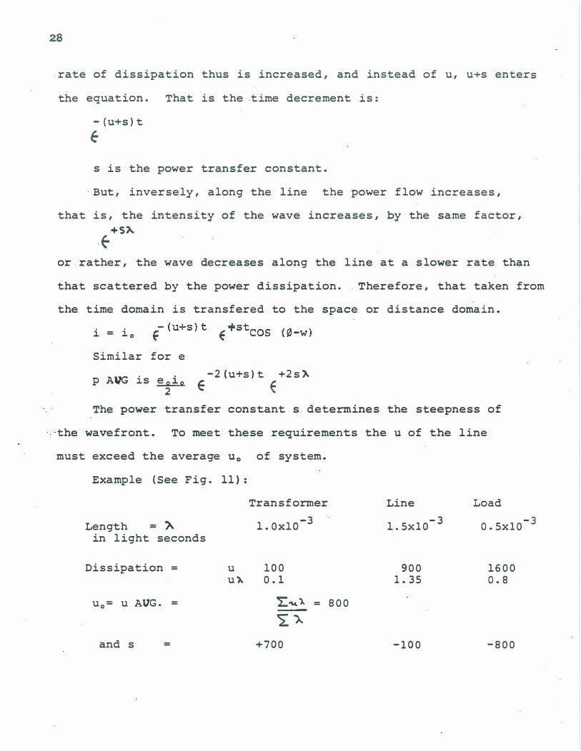
28
rate of dissipation thus is increased, and instead of u, u+s enters
the equation. That is the time decrement is:
-(u+s)t
e s is the power transfer constant.
But, inversely, along the line the power flow increases,
that is, the intensity of the wave increases, by the same factor,
+5). Eo
or rather, the wave decreases along the line at a slower rate than
that scattered by the power dissipation. Therefore, that taken from
the time domain is transfered to the space or distance domain.
i = io
. Similar for e
P AVG is � 2 E
-2 (u+s)t +2s)'
E The power transfer constant s determines the steepness of
-the wavefront. To meet these requirements the u of the line
must exceed the average Uo of system.
Example (See Fig. 11):
Length = " in light seconds
Dissipation =
uo= u AVG. =
and s =
u u�
Transformer
-3 1.OxlO
100 0.1
L:"",'). = 800
�A +700
Line
1.5x10⁻³
900 1.35
-100
Load
0.5xlO-3
1600 0.8
-800
XF,/IfR. "1--11,1',
, - -I
F . , w D ,
,
J./NE' J.OAl) • VW\
, - .
,
}b��� � __ � ____ �� __ � __ � • 1)/'STAA..<;c
�
R ' a , , L •
..
• - - -- "" " "" 'P' . - "' •
'X�;.fp. " � nn"1sCS"'
• ,. , , , ,
,
l./A/e
, , , ,
.lOAD ,�
, , ,
?OIuCrl •
,
,
,
' . , • ., # _ • •
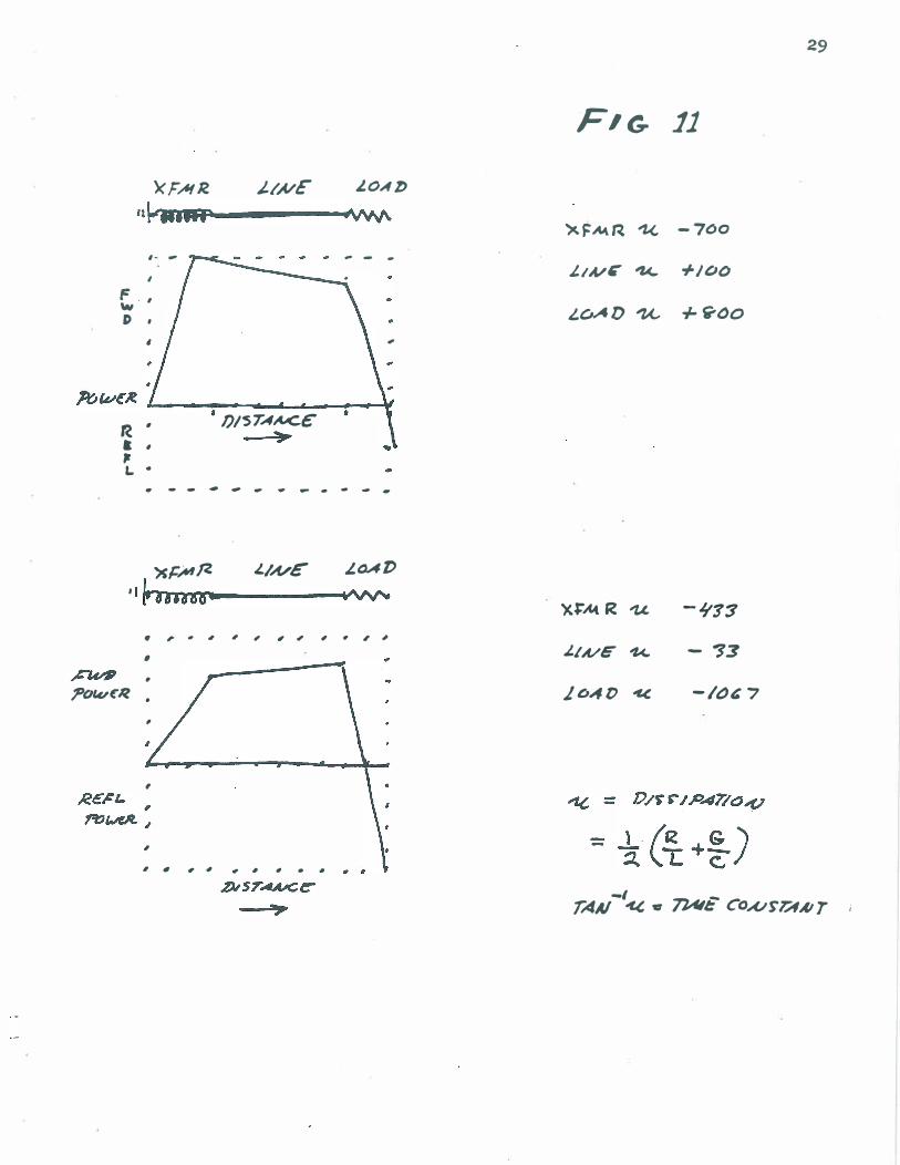
29
FIG- 11
�FM� � -700
J./A/- "Z<... +/00
L.OAD u +w-OO
'XJ:'MR u -Jt13
J.IA/C 'k. - �3
Leult) "" -1"& 7
-I _ rAAI "" c 7JAl1: CO,u�VlAI T i

Tne transformer thus dissipates power at a rate u=lOO but
sends power at the rate of S=700, or seven times as much as it
dissipates by internal losses. The load dissipates power at
u - 1600 and receives power at the rate -S=800, that is � the power
it dissipates is suppl ied from other sections, in this case the
transf orner.
The transmission line dissipates power at the rate of u=900
only a l ittle faster than the system Uo of 800; and the line receives
power at -S=lOO, that is, receives on�y 1/9 of its power from the
transformer; the rest comes from its stored energy.
For the special condition of waves increasing in magnitude
towards lead;
Transformer
'). = lxlO-3
u = 100
�= 1.0
u = AVG u = 0
S = +433 +33
L ine
3 1.5xlO
500
0.75
-106 7
Load
-3 0.5xlO
1600
0.8
That is the power transfer constant of the line has become
positive S=33 and the line now assists the transformer is supplying
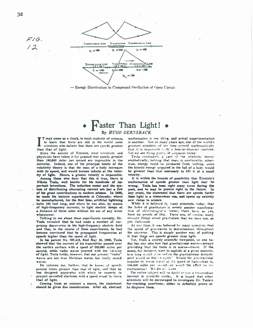
power to the load (See Fig. 12).
The preceeding paper has attempted to show the considerations
involved in the optimization of the Tes la tran sf ormer . T he enormous
number of factors involved make this a difficult task indeed! The
authors of coil analysis have come up with conflicting results and
an attempt towards resolve has been. made. solutions to the differential
equations have not been given due to lack of generality of those

3 1
ava i l able and l ack o f space .
I t ha s been ment ioned in papers on the s ub j e c t o f coi l
o sc i l lation s tha t the ory doe s not ma tch prac t i c e . Much more
exper imentat ion is ne c e s s ary . it a l so might be pos s ible that
)s -- - doe s not give the proper ve loc ity , remembering that Te s la ?:
c la ims that h i s ve loc i t ie s are f a ster than l i ght . For further
informat ion see :
1 . ABNORMAL VOLTAGE S INTRANSFORMERS . J . M . Weed . Amer i can I n s t itute o f Elec tr ic a l Engineer s . Sept . 1 9 1 5 , p . 2 1 5 7 .
2 . ABNORMAL VOLTAGES WITHIN TruL�SFORMERS . L . F . B lume . F eb . 1 9 1 9 , Amer ican In s t i tute of E le c tr ic a l En gin er s , p . 5 7 7 .
3 . ELECTRIC WAVES , D I SC HARGES AND IMPULSES . C . P . S te inme t z
4 . TRAVEL IN G WAVES ON TRANSMI S S ION SYSTEMS . Bew ley , L . V . 1 9 3 8 , 1 9 5 1 . Dover .
5 . D IELECTRIC PHENOMENA IN H I GH VOLTAGE CABLE S . D . M . Rob in son , 1 9 3 6 .
6 -. ROENTEEN . RAYS AND P HENOMENA OF THE ANODE AND CATHODE . E . P . Thomp son. 1 8 9 6 , Van Nos trand Co. , p . 9 3 ( Ke lvin) , p . 1 36 ( 're s la ) .
•
,2
Fl c;. . / � 1 1· ... 1111111 1"'on Lil1� Tl .... l�.!Urll lf"r T.-anan",.!',,,, .. Lilt�
I u _ � U - :IOO
U - .00 �
_ Energy Dist rihution in C'ompound O!;rillat ion uf ()pen Circuit .
• Faster Than Light ! • By HUGO GERSSBA CK
IT may come as A �h()(k, to most 5tud .. nt� of scien.:e, to learn that th .. r� art' �ti11 in tht' "'o rld some �('i,.ntists who helie .. � thAt ther� li r e .pt't'ds llr,.ater
than that of Jip:ht. Si n('t' the advt'nt or F.instein. ",osl �d-nt i� ts and
physicists have tRken it rur Il'ranled thRt & peel\. jrr,.at,.r than 1 86,800 mile� per sf'Cond art' impo.si ble in the universe.. Indeed, one or the principal tenets of the relativity theory is that the mass of a body increases with ill lpeed, and would b�me Infinite at the yelocity of lip1. Henre. a greater yelocity is impossible.
Among those who deny fhat this il true, there ia Nllrol& Tesl&, well known for his bUDdreda of important Inventions. The inductknl motor and the .., __ tem of distributing alternating narrent are INt & f_ of his creat contributions to modem 5Ci-. In 18n. be made his historic nperimrntl in Colorado ; when he _nufaetu� for the lint tirM. artificial lirbtning
I bolts 100 reet long. and where he was abie. by meanl of high-frequency currents, to littht elt'Ctric lamp' at & d istanC'e of three Dliles without the USe of any wi res whatsoe"er. •
Talking to me ahout the� exp,.riments recently. Dr. Tesla revealed that he had made a number of 5urprisintt diS«'o"eries in the high-frequency el,.ctric field and that. in the course or t� uperiments, he had become convinM that he pro"attat� frequencies at speeds Nlher thaA the speed of li,ht.
In his patent No. '78'7,112. filed May 16, 1900, Tesla ahowed that t� current of hil transmittu passed over the earth', surfaC'e .·ith • speed of 2!12,880 nl i lt'S per �nd. while radio wayes proceed "' ith th,. - el 'H'i ty of litrht. Tl'sla holds, ho..,,.v�r. that our vr�.en � "rRdio" way ,.s are Dot trur H,.rtzi.n "'awes. bUl r�8 l 1 y so:.tr.d w.ves�
H� informs mt'. furt!> .. r. thu.t he k,WW, tlf sl' .... u� several t imes grrater I han that nf IiJrht, . . nd thllt he hal designed apparatus with "' hkh he ex pe('ts to project so-<alled eledrDns ... · ith a sperd ,.. .ual tll t",i"e that of light.
Coming from 10 eminent a IDUI'Ce, the statftnmt should be (iye due conllderation. After all, abstract
nll.th�mllti("s i< !'nr th' l' lr. and a("tual ex�r;men tation j� ano t her . Sut </'I :nan�'- years allo. one of th .. "'orld's jrrrs t .. " t lO("ienti< t - of tl'", t i me r ro"rd �nath"""" t i ", .. l Iy t t . ... t i t is im pt·;: .or. !� : . • t!�- i< h,.a\· ier-th,l n -, u r � I l .. (' h i n .. . Yet "'e ar� t!y ir.i/ r ;"� " "f .. j rl ' lan .. � l oday.
Te�IOl t·CH .. t rHu :('t. .. part , , � t h.. :r l R t i \'it� th ... , n· emph .. t kall�·. hoI t1 i ." th.t m L<. is u n . I !"�Rb!e : ot�r",· ise. enerltY ('ould I,e i'rn<l .. ('� from �lothi nJr. "i n('e t� kinetic ent'r;r�- II('quired in the fall of a body would be greater than th"t n«f'!>5&ry to lift it at a small veiO('it}',
It is withlll the bounas of posslhility that Einstein's mathematic:a of .peeck «""Ster than litrht ma�' � wrong. Tesl& bas bee ript Ulany tirnes during thr p .. t. and he _y � PI'09f'ft ript In the fatun, III any "ent. the Itaftmrnt tNt there . an s� fastrr thaD lipt Is & tnmendou 0-. aDd. opeDI up elltirdy new "ilt .. to 5Ci�.
\\'hil,. it is �!i,. .... d r\ !."&nt' St'ientists. t" da,·. that the ( .. r(o,. of /travit .. I •• ,,, · i:i In-�Iy another m.';i{estat iun of .. h·,·t r"r'i&{". ' " "'''YI',:. I hrr� h,,,·... a. ,·et. h,."n no pr,oo(s of t his. Tn..rl' a re, of . ·t'u rsl'. n.:"n\· oh" 'urp I h i n ,. ... .. i"'ul frll \·i � .ti"n tha I we ha" e not, as y,.t. f.t l :"l l I ... d .
At 0 1 , <, t i lll�, i t ..... belie"ed h,' :nan \" <cie" I j .ts th.t t he sp .. ed of j[r.l , itat inn is ift5hn tan;"u � th
'ro" �hou t
th,. un ; ",.r",.. This is sin'ply &S'Icoth,.r way of putt ing it that theit' art' & � !I Ireater I h an Ii!!,hl.
Yet. from a s t rictlr M"il'ntific: Yie.·point. 110 "ne t� day has Any ide. ho .. fast jtra"itat i,'nal wa" f"'-always p ro\'idin!l' th"t tht' fo� is ill :tar .. _tr ..... l. I f the moon, fur in<�ar.r .. , "·er,. to esplode at a jl'i';en morn,.n t. h, · .. · I"n,l[ ,,· . . , , ! , I ; [ i· .. i ... r . • rt' thr �r" .. i t . l itJn"j di�tu rban .. '; ,,· ,, :.z ! d 1If' felt , " ,,:.,t:' ·· Would �h .. j."TK d t a t :nnal impu lse o r ,,· ,, ' ,.s [ � � \' <' ! .. I : 1 ·,. s' ..... d of l i ir h r --that is, 1 1<6,000 nult's r .. r . ... · ' . nd · �r .. " ,, 1 1 the e /fcC't I .., i ., s t tl n t.n�ou.); : \\ . ... d n fl" � :.o ..
The- f'ntirf' ... u hjr(" t ..... 11 �o d.;nd,t :. " H .. ..... It t rr : u r- uduu s int .. rest in s,·i .. n l ific: cirC'le",_ It i6 I"'ped that other l('ienti�t5 ",i l l he ent'oura� to in"'l"lIb,ate Dr. Tesla 's f ar-r .. �hing a.swrtions ; either to definitely proye Dr to disprove thenL

'No , 6 4 9 , 6 2 1 . N. TESLA. Patented •• Y ,15 , 1900
A P P A R A TUS FOR TRAII S . ' S S I O N O F E L E C T R I CAL E II ER6Y.
( .. ... . . , )
c.
I.
UNITED STATES PATENT OFFICE.
N J KOLJ. TE� I . A , O. N E W 'iORI{ . N. Y
A P PA RA T U S F O R T RA N S M I S S I O N O F E L.E CT R I CA L E N E R G Y .
BPEClnC.A.TIOH lol'lllo.lD� put or Wt&en 1" ..... t Jfo. M8,81U, datad Jla7 I ll, 1800. on,; •• 1 ."Ii .. ti-u II .. �"r :, ll'7 , leriu ... laCi.'U. blYloIocI ... t" • • ,�II_t1 .. II .. r.� I t. 1 toO. leri.l
••. e,710. I •• cod.l ·
'Tn all u·h mn ,t ",all CD"""7'1I: elevat ion sui table for tbe pu rposes 01 "·:ln�· Be tt k nown that I, N I KOLA TaLA , a eil i ' l m ission . Tbe ot.ber �rmi a31 of the secoodnry
zen of t.be l! n i loed Slales, rMidiDf At t.be bor· A, is eon neeted II> _rt.b, and, if delli red , to ol\�h oC )f anlultlan , in the cit)" 0 New York . the pri mary al .. .. io order th:\t th" latter may
5 coun ty anu State of Ne- York, ha�e inveDtf'd be at " u " .. tan li�I I! t be same potential as lho 55 eertai o n ew a n d useful IDl provemeou iD Ap· adjaren l portioo!t or t he aecondarr, t b a!! i u p:uatus {or tne Tranam iasion or Electrical surinl: lla fety. At the reeei viDg - lltation A Energy, or .·hlcb the folJowing is a spP.Cifica· Lraosformer or silll ilar �nstrncLjon is em · Lion , reference Uein� had 10 tbe d rawio.g ae · ployed ; but in thi. e .... tIM IODJrer coil A ' eQIt·
10 companyiag aud forlll ill2 a part oC the same. ati LoLes the primary, aad tbe shoneI' t!oil C' 60 Tbi. llpplicat.ion ia a division of an Applica· t.be eeeODdaf'J', of the ttaDSformer. In t he cir·
\iOD flIed by me 011 September 2, 1 1!97, Serial cuil of the laUer are coaDOCLed lalll p3 L, ." . lio. 6SO,:U3, eo tl tled " Syatems of tl"1lDsm is· to" If , or oLher devle. for utiliziog t be cu r· alons oC electrical energy," And is baaed UPOD ,""ot.. Tbe "Jevated &.erminal O' cooneoc:u wit b
15 Dew and uNfu l reat.nree A"d combi natiolU of the ceDter oC the coil A', aDd :ht' otber ter· ciS appatat.as sbown aDd dfllCribed i n Aid appli- m l Dal oC saHi eoll is coaDected to Mrlh an.l coaUoa for carryinr oaL the Dlethod t.berei n preferably, alao, too Lhe coi l C' for lh(' reuons diecloeed Aad clai med. above I�ted .
The invent ion whicb forDis tbe I>nbject or The leD1ti. of tb .. Lhio "' i re (,NI in each 10 my preseDt Applicat.ioD com prises a trAnsmil· trAII.Cor.ner 8houl":' be appro x i mately ODO· 7"
lio; ooli or eODductor in which electrical eur· quarter of the .ave leDgt h of Lbe elt'ctrie dis· r6D ,", or oecillatioos Are produced Alld wbiob torbanc(' io the cireui t, thili .. ti m.�e boiDg ill arrang.a to caUN laeb carreDta or oac:illa· baled 00 Lbe velocity of propaga .. ioD n( the &.ioa to be propag"ted by conduotioa through cllstllrbAnee tbroQgh the coil ilL'tolf and tho
'5 t.he Dalaral mediulli from oDe poiDt. &a aDoUier eircuit. with wbicb It is d .. igoed to be aeed. 7S remo&.e tJ-erefrolll ADd a receivlDK coil or coo- By ""y at ilI ust.raUoD , if the rate at which d llcfor a& Illoh diAaDt point ad"pLed too be es· the CUrTent tra\'erMII tbe circuit i nclud iDg clt.ed by the OIIcillaUoDI or CUn'eDta propa- Lbe coil be ODe hUDdred aad eighty· Ii \'e t.bOD pLed from tbe traDsmiUer.. &aad m il8l' per aec:ond theD a frequeDc)" of
30 Thil apparatUl ill lhoWD iD the accompaDY· n i De h U D d red aDd tweDty - 6 � � rer lecoad 80 Inr d rawiDg, which il A diarralli mat.ic m DS· woald mAi"at.aio DiDe hllodred aad tweoty.li,e traUoD of t.he &ame. ltationary moves in a oire.iL ODe lluadred
A II a coil, :tiDerally of maDY tu TU aDd or aDd t'lrhl1' � \'e tbousand mil .. loag aad eaeb A Te,.,. 1al'le diAmeter, woaDd ia �lral forra wan wou ld be two b U Dd red mllM ia leDgth •
.15 either abOat. a magnetic eore or DOt, .. may For IOcb a low freq uency, which woold be 15 be d .. lred. C II a aeeoDd eoll formed by a resorted to oD ly -bea il il l Ddi.apeuaable for oaahetor of III lIch larger aize aDd .maner the op8palion of motors of the ordillAry k iD.I leDrth 1tou.,d aronncl Alld in prox i m ity to tbe UDder the cond il.ion. abo" e .. umed, 1 would eoll A. aMI a �ondary or litty m il .. iD leogtb. Jiy
40 TIM apl"'I'Atu. at' one polaL i.e used &I a aach aD adjusLment or proport.looi D g of tbe 90 UaDalllilter, C.he coil A in tbis cue consLiLot- leDgth of wire i D the seeond.ry &:oi l or coila iDC a hip·tea'i9n, MCOadal'1, ADd the eoil C tbe poi n u oC highest . po:.ential are made k» tbe primary, oC m uch lower teaaioD, of a trans· coiDcide "' itb the elevated term i nAl. 0 D', fj)rmcr. ID lbe circlIil of the pri.D"ry l: ia ia' l ADd tt "boll hl be und�rst.ood tbJ\t whatever
45 elueled a aui lAule aouree of eorreD t G. One len::th be �l .. n too the w i res I bis rt'qu i rem "nt 9S t.ermiDAl of tbe aeeonllary A ia at the ceDt.er sbo u ld be eODl piied with i n ordt'r lC""ooLAin oC tho .plral coil , and frow to ia term i Dal the i tbe best rea u l ,",. currellt Is led by a cond llctnr n to • tern d Dal I I L w il l be rt'ad ily u ntleratood tbAt w h e D t.i", n, prt' Cerably of large sllrface, formed or abo\·o · p rMcr i bo!-d relation, es iat t b .. \.)oal {'nn · ·
50 mni D l n:aed by Buch me:\116 as a balloon at aD : d i lioDS Cor resoDance bet_MD tbe tr&n,m l ,· . o e
t
lj np; and recei v i n g circ u i ts Are AttAined, and Ofl"i n ci to the taet that the poin� of h ighest polent illl i n the coi ll! or conductor.. A A' are cOlucirie n t w i t h the elevated term i n Als the
5 maxi m u m ftow of cu rnm t will \.ake place in
the t'll"O coi ls, and this, further, neceSSArily i m plies that the cApacity and inductAnce in each of the circni� have' linch vai lles as tG secure tbe m08� perfee, CODdition of syucb ro-
10 nism witb the imp� oeclllaSions. When the aouree of cnrreDt G is in opera
tion And producee rapidly pulaatinl or oecil. lating curreate in the circuit of coil C, oor
responding iDduoed currentl! of very much 15 hieher pO\enUal are generated in the aeoond
ary coil A, aud since the potential in the same gradually increases with the number of turns toward Lhe center and the d i fference of potential between the adjacent turns is compara-
10 tiyely smalf .a very high pdtential i mpracticable with ord inary coils may be successively obtained .
As the mAiu object for w h i ch the appr.rll1 us is designed ill to prod u ce a c u rrent of es:ce&l'
2 5 · l \·ely·higb poteu tial, tb is object is fllcilitAted by "Usiug a primary cu rrent of \'ery consid· erable treq uency ; bllt the frequency of the
c u rrents is in a large mel\"� l I r� arbitrary, for i f the poten t ial be snttkien t l y h i gh Rud the
30 term l D als of the coi ls be ID A i n tai ned at tbe proper elevatiou wbere tbe fltmosphere is ",relled the stratu m oC all' v; i l l se r,e Pol; � con · d ucting medil lm for t h e c tl rr" n t prod uced And the latter will be trans m i tted throngh tlJe
3S air, with. i� may be, even less resist Ance �an through an ordinary conduct.cr
Aa to tbe elevation of the termi nals D D', It is ob�i01lS that this Is l\ mAtter wbich will be de&enDlaed by " Dumber of things, AI' by the
40 AIDOGDS aDd quality oC the wort to be p91'ronaed. by the condit ion of She atmosphere, and alao by the eharoiCter of the 8urroundiDg countl'y. Thu it there be high mountni[l!! III the ,.ici1Jlity the termiuala IIho;Jld bo at A
45 greater height, and generally they 8hould al· "'18 be -' au l!titude much greater than that of the highest oOjt!etB neAf them . SincII by the meau deeeribed practiCAlly aDY potE:n tial that is desired may be prod u Ct!<! . the c u rrents
So through tbe &ir atrata may be very small. th ua red uctng the 1088 in the air,
The apparatns at the receiving·atation J'&o .panda to the corren ti! propagat.ed Crom the transmit�r in a man:!er w hich ;rill be well
SS o nderstood froID the foregoI ng description. Tbe prim.". circuit of Lbe receiyer-tbAt is, I the thin wire coli A·-lit exeit.ed by the cur· reDtA propagated by_ conduction th rough the 1:l�rVeDiDg lIatural m�icm from lhe tran&-
M lII iUer, and theee currente i n d uce in tbe secondary coi l C' other currectA w h i ch aNI D tUized for operati ng tbe deviCM i n c l uded in tbe C l rc ni t thereof.
ObYiously tbe ree81 v i ug-eoi ls. t rADsform · 65 e n!!. or other apparaL Il8 may b! movable-All,
(or instance, when tIley are carried by a ves· \el fto&t.in� in tho Air or by a sh i p At IleA. I II
t b e former case tho t'oll l lection of ono terlD i · nal o f the recei \' in� apparat.us to the ground
- m ight not be permAnent, but m il!'bt be inter- 70 m itlently or i nd ucti vely est.a.bl isbed withou t departi ng from the spiri t of my inveD tion.
It is to be noted thAt the phenomonon here i n voh'ed i n the transm ission of electrical energy is one or true cond uction and is not to 75 be confouDded \vitb tbe phenomena of elec· trical I'Ild iation whicb have heretofore befon observed and which from the very nature and mode of propagation wonld render practiCAlly. imy.l88ible tbe tnulam_ioo ot any appl"ft· lio eiable .moun� ot eDergy to auch d islAncM a.are of practical importAnce.
What I now claim AS my i n veDtion is-1 . The eom bination with A transm iLti ug coil
or conductor connected t.o grou nd and to an Ss elevAt.ed terminal reapoctively, And means for producing therein electrical cu rren� or oscil , lations, of A reeeil"ir.g coil or ccond llctor si mi · larly con nected to �roll ntl nnd to an ele\'''ttod term i n al , at a d istancs from tbe t r8 nslD i " �I) ting-eoi J -And Ildapterl to be esciled by cll r · rents CAused to be proPAPu·d ( ro m tbe fla m e by conduction throuL'h the i nlon-on i n !: Dat· u ral m ed i n m , A ! !Condary co u d u c tor i n i n · ductive relation to lhe r�c�i \· i l l �.co n d tl ctor 9 5 And d et' i ce8 ror ut i l i:: ing t h e c U I're:!! i n the circuit of s[. i d 3econd sry con ,.l t: ctor. AS set.
forth . 2. The com bination w i t h a tl'ansm i ttl D g co i l
or conc uct o r bn.Yi cg i ts ends coo uected to 1 00 r;,rocnd and to au el�t':.:.ed term i nal respec· ti vely, a primAry coil in itul uctive relAtion thereto SOC " source 01 eloctrical oscillations in said pri mary circu it, of A receiving conduc-tor or coil having itB eods connected to grouDCl 105 aDd to an ele\'atfd t.e:'1Dinal respectiveJy aac! adapted to be excited by cnrte:!ta caused to bo pro� from tbe tranamitter tbroqb I.b natarat medium a.ad .. MCOQdary circuit in it!daetive relation to the receiving-circuit 1 . 0 and rec::iviog devicee connected tberewith . &II set Corth.
: 3. Tbe combi n&tion wi t b 'a tr&nsUl i t ti nr I n' stru mect com prising A tran8f�rr::ler· hat'i np: its S8COOciAr.y cou nected to gro u n d e.nd to aD ele- I I S vn.ted term i n al reapecti \'ely, and meanl Cor
. imp:-euiog eleetrical oeci !\Iltions uponjt,a pM' :nary. of a re-oei vinB instrument comprisiDg a transformer haviug i ts primary aimilarly oonnecr.eci to grouud and to an elevat.d �r· J 10 m i aal. aDd a tranalaUDg device conDected with its NCOndary, the capaoity and iDdue&ance of the two traneforme!'ll baving Inch val ues .. to leCure synenroniam with tbe im· preued OIOmationa . .. set forth. I I �
4 The combillation with . transmitting In · strum8Dt compriain� aD electrleal tran.eCormer b�vlng itA eecGndAry �onnect.ed tc ground and to aD elevated termtnal respec· tl vely, and meanl for i m preMlng electrical I .JO oscillations Ilpon It. primAry, or a recei v i ng instra ment comprtal ng a traneform t r bavlng ita pri mary aimllarly connected to grouDd and to an ele,..ted tel1ll1D&l, aDd a traulal-
35

649,6lJl
i og r. e �· i('e cc·nnected w i th i : " sec o o d ary. ti lt' I I Elns:-th of the disturbance p r,'pRgated , a,. st't r.apaci ty aDd i nu u·:tan r .. of the lIEl("onuary of ! furth . . tbe traosmi ttinS IUl ll primnry o( tbe recei v · I 8 . The cl l in h i nal;oo ..:" i th a !. onnsm i tt i n !; co! l ing i nst.ru men ts ha\' l n g sl Ich �':\ lues s.!I t o �e· or l�oodu ct.or coo n ected to gro und anu to an 3 5
5 cure synchronis n , w i t h t he hn p ressed osc i l l/\· �leva!.ed It· l' t n i ual respeet i . ely, snd adapted Lions, aa eet fortb. . to CAuse thl: prolJ"88tion of cu rran ts or asc i i ·
5. The coln bi nation with a translD i Lti ng coi ! latiGns by couductior. tbrousrll t.he natu ral or coDd actor COnDtlCted to ground and An ele- medium, of a recp. i \·ing,cLrcait similArly ConvateeS armiaal respectively. and means for nected to ground and to an elevated termi· 40
10 produciag electric:al current. or oscillations nal, aad of a capacit.y and inductance lIuch iD tbe eame, of a recelviug coli or coaductor Lhat ita period of vibration is t.he same as that almilarly Cf)Dneo&ec\ to grouDd aDd to an ele- of thtl' transmitter, aa Bet forth. vatee! termiDal and lIynchronbed with t:le 9. The transmit,t.ing or ' roeeiving cfreuit
. tr8Umlttiag coil or coad actor, u set fort h. herein described, cODnected to ground and 45 .s 8. The combination wit.h a t./'Ansmitting i n · an elef'&.Led term i nal respectively, and ar·
etramen t com prising an electrical traos· ranged i n such Ulanner that the elef'ated ter: former. baving ita secondary con nected to minal is chargftd to the mAXi mum potential ground and to an elevated t.erminal respec· de\'eloped in the ci rcuit, as set forth. \ively. of a rec:eivio[t iOIl\rament comprisi o g 10. The combiaAtion wit.b a transmitting So
10 a t.raaeformer, havlog Ita pri mary sim i larly cciil or cond nctor conoected to grouod and to connected to grouad aud to an elevated ter· an ele\·a!.ed terminal respect! vel) of a racei v· m inai , the recelving·coi l being sy�ch ronized i og-ci rc u i t hAvi o g a period of vi brat.ion cor· witb that of the tr"nsmitter, as set fort.h. respooding to that of the traosru itting-circ 'l i t
7 . The combi DALioo 'Wit.h a \ransmitting coil and si m i lArly con o ected t" ground and to an 5 !' 2S or conductor connected to groond and to an e le\·at.ed term i ual and so arra n ged thl\t tb(\ elc\'l\t8l1 terll\ i n�l respecti vely. and meaDS for I ele\'nted term iual i " ("harged t o the b i gh",,!.
p rQd u c i u g e l ectrical corrents or oscillati ons I potential oc\'el.)Def] in the C'i �C' l\ i t . l\s set fort h i n the sacc, of a recei f'ing coil or cou d uc!or I N r K O I..-\ TESLA. 8l1n & 1arly connected to grou nd and to an ele· I �"' ; t n es5es :
30 va ted term inal, the sllid coi l or coils hllv i n � i P A R K ER W . P ,H'£. a le n gth eqllal to o n c · ql lnrtllr' v[ tl :a � :\ ',' O . :,i .\ �':ELLt':' :1 \ I !. r: y .
P-360 N. TESL A .
ArfA ii A T U S fOF. i R A S S M I TTINO ELECTRICAL EYERG'\. . A p n I C A n o � r : u : ., J A W . l B . B 0 2 . I � W t W t D . � t 4. I VO?
1 . 1 1 9,782 . Patented Dec. I, 1 9 1 4.
..Pt::l!��.E
; a � /
/
, � ... "
i ; " "
j ' I , I : I I ' , B' I i · 1 ,
p-
. .
.4
\ \ ' l .
, .'-', � . �:
37
. )8
UNITED STATES PATENT OFFICE. NIXOLA TESLA, OF NEW YOB.lt, N, y,
�p ABATl1S FOB TBANSXITTING ELEC'l'lUcaI. ElfEBGY,
t,1 19.732. IpeC1acaUoll ot I.etten hteat. Patented Dec. 1. 1914. AppllcaUolI tlell Jallury II. 1102, Sertal liD. 90.24$. llellewell .a� to 1107. Serial liD. 371.117.
To 1111 ,rJ, llm it m fly ronurn : Be it kno"'n th:l t 1 . X I KOU TEsL.\ . Il cit i '
7.t'n of thl' Fmted !'Ot!ltl'l<. resi c.l i n � i l l till' boron:;:h 4 . f M:Ul h a tt:J l I . I II the Clt�' . (·"ul lty .
.. and :-;tah' of Xew Y.wk. ha \"(' i n n'lIh'l! I'el·' tai n 11(,,," :10.1 u!O!' flJ l l ru I"·')\ t·lIl1"nts I II A ppa · ratll!'l for Tra n sm i t t i ng j·:I(,ct l"i (·:1 I Elll' r:;:�' . of " I I I I'l l t h.' fol lllw lI Ig I S !l !ipt.'c i l ic:l t UlU, ,·d erclu·c 1'I.' i n " had t . ) the tll-:I \' IIII! :1I.·COlII
ID p:III.\" II I:;: a llt.i f�)rm:ng :1 P:I I·t o f t l lt.:- !'a m(', In endea " ortng to :ul:l pt cn rl'('nts 01· eits·
('ha rg('s of n!ry 11 1gb tens!on to \"Iniou!> \·11 11 1 · Ilhle lISl'S, as the distribution of energ," through ,,· i res from Cf'ntra l pla nts to dist:lltt
Ja plAces of conslIm ptiun, or the trn nsmisslOn of po,,"erful distll rham.�s to gl"t'3t d ista nces, tlu-ough the- n3tu I":1 I 01· non,art iticla l me-d i3, I h3\"e ('ncount('r('. 1 . h lticl l itics I n con fill ing l'onsi d('ra hle 3 mollllts . . f ('Iectrit'i t \" to t he
20 cond llctol"S and pn'\\:nt i nJ; i ts 1(,:l k·!1 �c 0\"('1" thei r Sl Ip/)Ol"t::: , 01" i t;; e"'l·:t l '� intn t l l(' : l I i l l .il'nt air, "' h i l' 1 :l I n-a ,'·s takt.·" pl:H"C w itt'n t he ('I(·c, tlic sllrfac� dl'nsih' n·:I(: I I ,·s a re rta i l l '·a l l l" .
ThE' i llll'm:lty of thl' e !l t·l"t "f :I t I":I Il",m i t · 26 ling c l r.-u i t w iih a fret' or clc'· :l h·. J tt'nniu:d
is proportitllla tl' to the IJII:l Ilt ity of (, It.,('tri(" ity displ:ll'(·d, which is d('lt'rm i ll" t l I ,.\" th(' product ot th(' capal'ity of tilt .. cl I·cl l it. thl' pl'('!!!'lIrl'. and tift' fr('(lul'ncy C l f t he l · l I ITClltS
:.n emplon'd . To prOtl l1l:(' an ('\ecl rll":. 1 mo\"e· ment of the I"t'llui rt'd magnttUlle It is de, si rablr to cha r�l' the ternun31 :18 h igh l �· :IS pos.c:ihll'. fCII· w h i l,' a great (ll1a llt i t�, of ('Il'c, tri('i t�, may :111'0 lx> di!'placl'd hy :1 la rge
36 cn P:lci ly I'h:l r;:ed to low pl·l'SSl\ l"t', there Il re d isud" ;lIltagl"l' met 'nth I n many ('ases w hen
the form(" · i!' macll' tllO la rg�, The ch id of thl'S(' a n' ri llr to the fart thal :In i ncrease of the cll pal" lt '; e-nla l ls :1 lowering of the fre'
40 qllt"IIC"�· of t h l' I mpul:;t·s or disch:lrges and a dim i nuti on of the ('nl'rg�' of ,· i hl·ation. This Wi l l be I Inti(,l'!'tood whel) It IS bornc in m ind, that a cm·uit 't"ith a la rge caplicity bt>ho\'es liS a ,;Iacksprmg, wherells one ""jth a small
46 Ca pll(· l t .\' acts hke n st i lf sprm;, vi brating mOl? ' I gorously. Therefore, In order to a tta i n thl' h l gl1l.·st poss, hle frequency. willch for certa t n pll rpo.c:es is a.hnnt a g!'llus and. a pa rt fl·om thal, to dl'\"E·lop the gl·(':.tl'st
110 eller�)" in sl lch a t rDlIslIl . tl l llg l' l rcl l l t , I em · plo," :1 I('rm i na l of reb l . H·I .,· sma l l 1':l p:1 (' i t�· , w h l ('h I (' I . :I I"/:e t o as i t i!!" :1 pl·essllrc ns prac, ticn!. lc . To n('('ompl i�h I I1 Is rCl'u l t I hnnl found i t i mperati ,·e to !'u const ... . ct the ell'-
66 t"atcd 1'0n.i l 1l'lor. th:1t it� nllU>'· !il lr C:lCt', on
which the electrical charge chiefl y accumu. lates, hns Itsel f a la rge rAd i us of cu n·nture, or rs composed of sepnrnte elcmf'nts ,,"hich, I rr·c"'pect, ,·e of thei r own rnd i us of cur" utur('. a rc 3rrang('d III close proxi mity to ench flO oth('l· 31ld so, tha t the outside idc:11 surfllce enwluptng them IS oC a large radi us. E"i-' elt'ntly, the 5mnl 1er the radi us of curvllture the g\"(�atel·, (or II. � \"t'n electric displlll'c, 101.'1�t, w t l l be the surf3ce-densl Ly and, con, 65 Sl'<1�ll'ntl�'. the I�\\"l'r the limiting pressure to wh ich the tennn�3 1 �3y be cha rged w ith out elt'ctrlclty esca pmg IOto the Ill r. Such a ternnn3 1 I secUI"e to 3n insulating support entel·mg more or less into its interi or, and I 70 l i ke"·I5e connect the ci rcuit to it inside or, general l�', Ilt points where the electric den. sity is SID31l, This plan of constructing.llnd supporting Il high ly cha rged conductor I hn " e found . to be of gre3t practi cal impor- 75 tanCt'. :l ft d it m:1y be usefully Ilpplied in many ways.
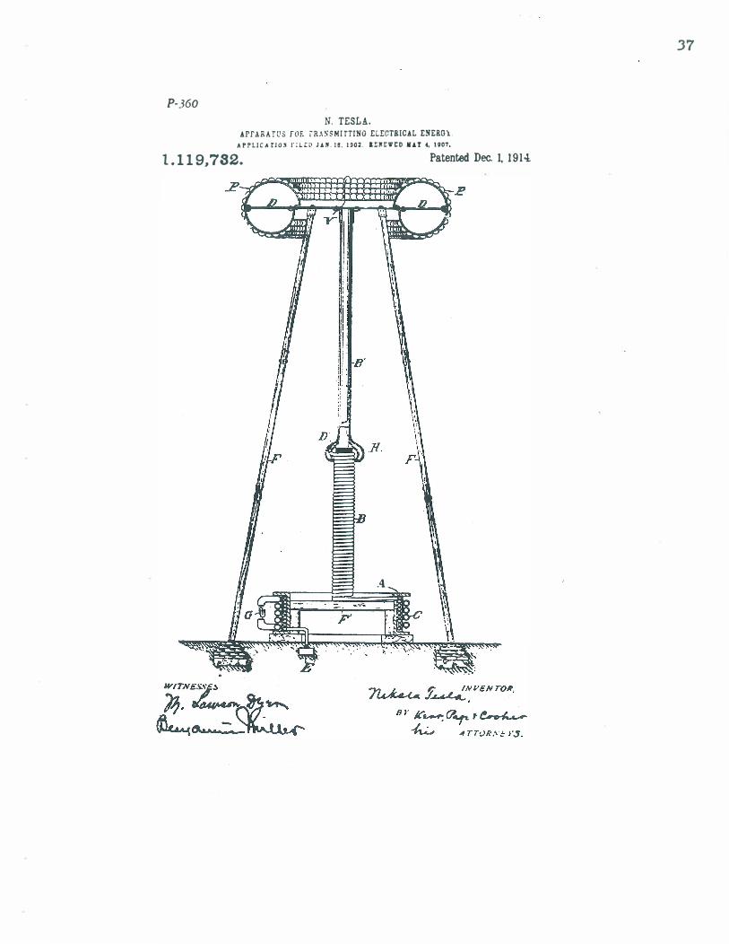
UefelTinl; to the accompllnying dna wing. t l l(' li�l I l·e IS 3 ,'it-w in eleution And pa rt ;-t>d i. n of :m impro,·oo free termina l nnd 110 " j r' · l I i t of I :l rgt' sUI·face ,,"ith supporting �t l·l Il·t l l rc ancl �neraling a pPllratus.
The tl'rmin:ll D consists of a su it ahly ",ha P<",1 metallic frame, in this case a ring of r.l':l rly cir('ul3r cross section, ,," hich is ('0" , II� ('1'('11 \\ ith hal f SJ'herical metal piAtt's P P, th llS l'nnstituting a " ery large condll('ting Sll rf:u:e,.SJnooth t.'n all places w here the elec, tric chllrge principal l v accamlll :ates. The frame is carried by a' strong plntform ez- !!Il pressly prorided for safety appl i nnces, in,;truments of obser"ation, etc., which in turn rests on insul ating supports F F. These !lhou ld penetrate fllr into the hollow space formed by the terminal, ADd if the electric II !) density at the points where they a re bolted to the frame is still considerable, they may be .specially pl"Ot«ied by conducting hoods AS H,
A part of tht! amprovemenu which form ! 110 the subject of this specification, the trans, !1litt i�g Ciz:c" it, in its seneral feot!lres, is rde-nt ,,·;! l W i th that dt'SCn bed and c1a lmeel in m�· ( I!·igin :l l Pntents !I: flS. 645,5 76 an-i fi49.62 1 . Th£' c i rcu it comprises a coil A w h ich i s i n 1 p !) I'lu!'l<" il1dlll't i ,·t' rdat ion ,," i t h a pri mary C, : md o n l.' e n d of ,,·hich is connected to a wnllnrl · plAle E, ,,· h i le i t!l other end is led t h roll�h a l"I.'pAr':1tr S(>1 f. ind u('t ion roil B a n d R ml'tll J l i� ('yl indl'r n ' to t.hc t.erminal 1>. ] t Q

1.11D,'7U
fi ll' ("f'nn<>d ion to the lntter shou l d al ways I ,. . m n ; ) ,' a t . or near t h ,' ("cnt er , In ord�r to < · " " 1 1 1 "\ ' : 1 � " l I Imet n('a ) <.l i "t n l >u I j" l l .. f tllf' ("u r , n ' I I ! . a " ; , t i lenqSt', w h e n thl' f!'l·q l l .'n (',v i l'
Ii \ ! ' I 'y h i /!,h and t he flo\\' I O f ) a r:.!" \· " l l I m�, the Pl'I' r"rJ l l n n re of the a pp:l l'a t ll " m l :.! h t he 1 m ' pa I red Thl' pl'imary e milY I lt' " x " lt .. d I n a l l Y t 1l',;i l'l�<.l m n n ner. from a sUIta ble sou rce u ( "t1 l'renls ( i . w h ich nUl)' be lin a lternator
10 or ("ondeo,;cr, the imp'>I"tant re<llI l rement Lein'" that t he n'sona n t ("ond ition is E'St:l h, l i sh�J . t hat il' tei sa \' , that the terminal D IS char:red to thE' Jll a x l mu lIl pressu rE' dE'\'el oped in t l tc ci rclI i t . as I ha \'e specified 10 my
1 5 oril!inal p:l ten ts ) ,e fl l l'(' re ferred to, The au , j lL'otmcnts shou l d I.IE' 1I I:)(le w ith particular care \\ hen the t J'nn�m ittcr is (lne of I!rcat p" .. ' er. not only on nccount of ecunom.Ji , out a lso in order to :lH,id "nn�E'r. I ha"e sho"'n
20 t h,a t it is prad icllhle to produce i n a resonnt, in,z ('i ITl I it as E A n B ' D im menge electri , cal a cti" ities. measu red bv tens nnd evcn hundl'c(ls of ihuusa nds of horse-power, and in such a c:isc. i { the points of maximum
2S pressure should be �hift.ed below tbe ter, Inionl D, :llong coil n. a ball of fire might hren k out and destroy the 1lUppcB't F or auy' thjn� el!>e in 'the .. ay. For � better ap' precJotitJD of the 11.8tuft of tbia dUlF' it
30. shoul<.l be statE'd. that the destnH:tive aebCIII rna v ' bke plare with inCODeei�te -rioleD�, ThiS 'l\-ill ct'.:Lc;e to he surprising .. hen it is hOnle In rnind, thllt the entire energy accu· Inn lnted in t he excited circuit. instend of re'
:lb < J l I i 1' inl;!, as u n der no rmal �orking condi , t i "n�, 1 ' 1 I t' ' i u a l 'ter of the period or more for ito; tra nsform a t i on fre>m static to kinetic (01'1 1 1 . m:l �' sp4'nd 1tsE'lf in an mcompsrably "1 I 1 :t l ll'r i nterval (If time, at a rate of many
4 � m i l l ion� of horse power The aC'CideDt is :' pt t o o('"cl l r w h�n . the transmitting circuit h<! lOg �trongl,v t'Xcittod . the impl'essed (}Scil, 11I t i.>nt-l 1I1'0n It ore ('a ulled . in any manner mC>l'e (lr I�� slId.len, til be more ra p id than
45 the frP(> osci l l a t ions. It is therefore ad, \'isHhle to I)('�i n t he odj ustment.c; with feeble and some,,' hat slo't'er impressed osci llations" strt'lI!!1.ht'n i n� llDd quickening them grad, lIol ly, unti l the apparatus has been brought
1>0 l IndE'r p4'rfec't control To increase the 'lll fety, I pro,i de on a coDvenient pi lice, preferaoh- e>n terminal D, one or more elements CI' p ln tes either of some,,'hat smaller radius of ('nr\'ature or protruding more or less be·
�5 YOlld the others ( in which c:a&e they may be of !larger rndius of l'Urnture) &0 tb.t, a�oul,d the r_rf"!'�lI re rise to a value, be�'ond which It is not (\ " !'i red to go, the powerful discha rge Illn \' c\ ,, , t t l l l t t ill're and lose itsE-1 f h .lrmlessly
60 in thl' a i r. SUl'h a pl:tte, per fllrm i . I g a func, tion si m i l a r to thnt of a sa fety ,' n l ve on a hil!h pre!'s l I re reSt'rvoir . is indic:oted at V ,
�t1 l 1 f l l J,th('r E' xtendmg the princi ples unue rl \' i n� my i n n·n t i on. �pt'Cia l re ference iii is made to coil B :JDd L�nduct or B' The
IlIttl'r il' in thE' form of a cylinder with smOOTh or polishf"d s l i r fa c :e of II radius Tlluch ) : I I'�f>r t h n n that of t i t .. ha l f spherical ele·n lf"nts I' P. lind w l dl'ns out nt the boU',:,m m t n :l / tooc l I I , t\' h lch "hol i i d be slottRd to 70 !1 \ old 11K" Il\' eo d v ('urn>nt.c; and the pur, � of w h i .:h "' I i i be clrn r from the fore ,zoing Thf> roi l R i" 't'olllld on a frame 01 d ru m J ) ' , of i nsl l la t lD� ma terial, with its t u rnl> duse to�ether, I ha " e disc�\'(>red thnt 75 wh(>n so wOllno the E'/feet of the small radius of cnr\ ll tn rl' I I f th(> w i re I L�I ! is O\'E'rl'.omt' >I .u) thf> ('oi l bt-h n \ t·s li S a eond l lr lO I of l n r� 1',l d i l lS of (·u n a tur ..... �Tespond l ,,� t o thnt Clf th(· rl n l ll l . TIl i s fea t l l rf> Il' o f consH iE'r, 80 II hle pr:lctil'n l I I l 1 pO I · lu IIM' a no IS :1 ppi i cA ble not on ly in thi" Sfle(" t . a l I nl't:lnce, but �n�ra l l.", For e:-:lI m ple, sl lch platE's at l' P, I I f termina l 1> . thou:rh prefer.l b l y of l n � r:l Il i llS of ClI rY " t.u rc, Ill·ed not lw neccss.'l ri l \' 85 so, for pr'''': l df>u oll l \' th:l t the indi\;du:il piatt'S or l'iE'n,pnt.<; (I f II hIgh potentilll cond uctor ()J t(,rJ l l i u fl l :I re 8 rrnn�d in pros'Illu tv to ench other ond "' itb their outer bolllldllnE'S .along an ideal symmetrica l en- . " eloping surface of a lar� radius of eun-atUft, the .d,·.ntar;es of tHe m�enuon wm be m<m! m- � fuJly ftIllized The tower � of the coil �wbich, if desired. may be enended up to tM tnrnmal D-shouM 15 be _"'hilt hf"low the uppermost turn of coil A, This, T find , I�ns the tendency of the charge to brt' n k Oll t from the ... irt' connedjn� both and t.o pass along the sup-port F' . - 100
H\lnng dE'scribed my in ,ention, I cllli m : 1 . :\ s II means for producing grea t elec·
tnt'RI actl \'ities a n'SODllllt t'ircu i t ha \;ng its outt'r l:()ndlJcti u� bou nda ries, 1l'hir.h nre ('ha r�t'd to a high pptential, arranged in 106 su rfncE'S of large ra dii of cu r\'alure so as to pre" E'nt leaklilre of the oscillating charge, sllbstll nti a l ly as .5('t forth, ,
2, In apparatus for the t.rnnsmission of elect I'ir.n I energy a circllit connected to 1 10 ground and to 11 11 de\'oted terminal and ha\' ing its oll ter conducting boundaries, ""hicb a re subject to high tension, nrran� III surfaces of Inr�e rndii of cllrt'ature substantiolly .s, lind for the purpose described, 1 15
3 . In n pla nt for the transmission of elec· tricli l energy without wires, in combinotion "'- ith a pri muy or exciting ci rcuit 0 secondIl" connl'Cted to ground and to an ele;ated Iotrmin,,1 IUld ha,;ing · its outcr condu�t�ng no boundllrif'S, " hich nre charged to • � potf'ntinl, IIrrangt'd in surfoces of lnrge n dii of cun'atu re for the purpose of pre" E'nt ing lea k a ge and loss of energy, substantioll.V lIS Sl't forth 116
� , As a meR ns for tnnsmittin" electrical t:nel·gv to a d ist ance through the naturlll m�u i lf 1\ gro l lndrd rt'Son:t nt circu it, comprisi ll� u pa l1 u pon wh ich oscillations a re i mpressed ond :mothcr for raising the ten- 1 10
.39

40
1,118,,"12 8 � i (,n, h :l \' i n l! i t!' nu l. ' r , 'on , l l l " t i l ;/! hOl l n c b ri O's on w h ie-h :I h i gh u'l l " j un I 'ha rgo' IiCC 1 ! /l IU iatt',., n rrn l l�I'd i n su da," '" of l a l'�I' rn d i i of curT:! , i : ;n ' , � I l l o:,ta llt i :l l l \' ns Ikse-ribeod , '
;;. ;" The Im'ans' for prod ucing ex<.'essi \'e
t,l(,(,tric pott>nti a ls ('on�isting of a primary exC' i t i n g ci rc u i t and a ",sonant secoodan' ha v ing 'its ouu-r cond�lcting \'!lements which II "' suhject to high t<'n"ion a rranged in prox-
H I imit�, to each other and in surfaces of lar/!t' radii of eun'ature so as to prevent leaka ge of tht" cha rge :md attendant lo\\'ering 'of pounti a l . suh"tantialh' as dt's('!'ibed,
G, .\ ci rcu it com, ;rising a pa rt II pon which 1 5 osci l la t ions a rl' i ll l p l,t'��d all . 1 I Inotlu,'r part
for ra isin$!' the �n;:ion hy r('son a nct' , the latter part lx-ing supportl'd on places of low elect ric densit:" and ha " i n$!' i ts outermost conducting boundaries arran/!ed iJi su rfaces
::0 of 13r/!e radii of ,cur\'ature. as set forth, i, In apparatus for the ,t�nsmis.."ion of
eleetriC:ll energy without wires a �ounded circllit the outer conducting element..'" of which have & grat �g:lu area and are
2' arranged ill sun:u:es of large l':ldi i of curvature BO as to pennit t.he storing of a high ebl 1"g'e at a small electric density and pre· " ent 1035 through le3kage, substantially as described,
8, A "'irelcss transm i tter c(\mprisin� in a r com bination a sou rc� of os.� i I l :l t i ons as a cOIl . ] t'nser. a pri m a ry e�!:'iti ng ri re-nit n nd ::. .5('('ondary grounded and elp\'at�d condl lct o:' the ollter conducting boundaries of which are in proximity to each other and arranged :: � in surfae-es o f large radii o f cur\'ature. sub· stantially as described,
9. In apparatus for the transmission of t'\P<'trical energy "..ithout wires an ele\'ated cond uctor or nntenna h:l \:ing its outer high 4 (' potential conducting or capacity e\l'mt"nts Ilrrangt"d in proximity to each other and in slIrfa c('s of la rge radii of cuC"'atn re !IO as to Q\'ercorne the e ffect of the small radius of cur\'llture of the indi,;du3 t element!! and 4 ', \t'ak:rgc of the charge, liS set forth.
10, A grounded resonant transmitting circuit ha,·ing its outer conductic/Z bounda ril'S arranged in snrfaees of lar� radii of ctll""ature in combination "'ith an ele. :'0 "attod termiWlI of great surface supported at points of low electric density, substan· tially as described. '
NIKOLA TESLA. Witnesses:
M, L\JlIION Dna, RrCIlAIlD DoNOV.:K.
.
Copies ot WI patellt ma,. l:c obt.a1lle4 for lYe cellts each, b,. lL44resJillC tlae U C_aiwoln ef h-.sta, Wa5l1!llctDa, D, c. ...

CAPACITIES · By
FRITZ LOWENSTEIN � rl£e r�1..
As the seat of energy of an electric31 field is in the space outside of the charged bodies we will consid<:>r the shnpe :wcl concentration of the field only, but not thut of the body it�elf. This distinction il' necessnry bec3u�e .cnpacities nre usunlly
attributed to the bodies charged , whereas the energy is exclucled from that space w hi eh i" . occupied by the body. Considering the space between t wo cha rged bodies a � the only seat of enC'rgy , the expression "chargC'd body " is b(':<t rC'plncl'd by " term i n31 surface " of the field.
Comparing g<:>omet ri c;l l ly similar elemC'llts of two g('Ometrically similnr fipld,.: . th<:> elemC'nt ary capacit ies arC' proportional to linea l dimC'n;:ioll;: . (SC'l' Figure 1 . )
Ext<:>ndinj!; thi� 1 3 \\' oyer th(> <:>nt iTe fidel hy th<:> integrat ing procl'>';;:. we find that geom<:>t rica l ly silll i lnr fi("ld� have c3pacit ies proport iollnl to the linea l dimensions of t he terminal surfaces. It i� to be expect<:>d . o t h erefore, that cn pacities expressed in dimC'll;;ion;: of terminal ;:urfaces �hould he of l ineal dimensions.
That the ca pncit�· i " by r,o mean;; a funct ion of the " olume of the field or of the terminal hody may hC' easi ly seen from Figure 2 "'herl:' a fidd <:>lement i;; increased to dOUble th<:> volume hy adding IJf' • PI'l'l'ented before The I nstitute of Radio Engineers, xc\\" York, Decem-
r 1 , 1915. 17

volume in the direction of the field lines and in a direction perpendicular to the lines. In the first case the capacity has been decreased whereas in the latter case increased, altho In both ca..c;es the volumetric increase is the same.
FIGt:RE 2
I t is �een , therefore. t hftt instead of being dependent on the volume , the rapacity i� rather a function of lineal dimension and therefore the mftximum lineal dimension predominates.
An interesting example of this predominating lineal dimension or "maximum reach" is given by the composite capacity of two wires joining at one end under various angle�, as shown in Figure 3.
FlGl'RE 3
When t he :m�le i" "mall the composite capacity is practically the �ame a� that of t he ,,:ingle wire, since the addition of the second wire hfts not increas('d the maximum reach.. . If the s('cond wire B he jOi llf'd to A. 'at an angle of 180 degrees, ' which me:ms in straight ('ontinuation of wire A the tota! " capacity has
18

oubled , as the maximum reach now is twice that of the single wire. \Ve notice also that by deviating wire B slightly from the traight continuation of wire A , the maximum reach of the
system is not materially altered, from which one may correctly c�nclude that turning the wire B thru an appreciable angle b does not materially change the capacity of the system. On the other hand a great chanJ!:e of maximum rE'ach is pro<i lw('ti by
variations of the anJ!:lE.' whE'n the two wircs arc approximately
perpendicular, and in fact t hc ca paeity of the total �tructure i�
most sensitive to changE'$ of angle bet ween thE' two ('ll'ID('nts at ahout 90 degrees.
In Figure 4 , I haw /ti wn a tal>ll' of {'apaciti('� per ('('nt imE'ter of the greater l ineal dimension of t he diff('rE'nt ('onfi�urntions .
() c =.'101
c-.}Z.t
o C-.l01
(-.I0 l F1GrnF. 4
In Fig:uf(' ;) t he WIrE.' A. B i s a""umed to he movpd I", the variahl(, ah:-ci,,"ae x , t lwreby gCIH'ra t ing: a conducting sh;et S,
I t is instruet i " e to follow the yariation of the capaeity Cz• 1 0

At x = tI the capacity is that of the wire Ca b ; as long as x is small the capacity is practically constant because the width of t he sheet is small compared to the length A B and a change of x does not involve a change of the predominating lineal dimcnsion ; however, as x increases and finally becomes greater than .-1 B, it a...�umes the part of the predominating dimension, and, indeed, the graph shows the capacity then to be proportional to x.
" I
"""--__ '- _ _ _ _ _ _ _ _ J FIGt.:RE .'i
Compurin!-t thc capncities of a sphere and of a wire, it is found t hnt the c:lpncity of the sphere is only three or four times as grcnt al" tht' ('npacity of the wire in spite of the million times greater volume.
I ha\'c !':poken of the eapacities of a wire and of other bodies inste:l<l of thr cap:lcity of the field simply because I do not wish to distr:lct uttentioll from the f:lmiliar conceptions. Let me an:llyze thr field �hown in FiJ1;ur(' 6, having two concentric �pll('re,; ;'''' tf'rminal �urf:\('e�, and defining :lS "volumetric energy · dcn",i ty" t hl' enerl?:Y ('ont:lillcd in one cubic c('nt imeter . As the encrl!y I)f a field (·I(,01('nt is mmle up of the product of potential alor./! the linl'''' of fon'(' within that ('l('ment and of the number of l ir.I'''' t ra nr"in/! it . thE' I'nerl?:Y of :l cuhic cent imeter of electric field i", proportiomtl to t hl' square of the field density. Since the field d(,ll"ity diminishes as the square of the distance from the center of ficld, the volumetric energy density diminishes with the fourt h power of the distanee from the eenter. The diagram to the ll·(t in Figure 6 ;::ho\\'8 the decrease of volumetric energy
dE'o"ity. Of /!rc'at l'r intcrl'",t t h:ln the volumetric energy density is the
lim':ll ('ll('r/!y clt·nsity . wh i ch may be defi ned as the energy contained
20

in a spherica l iayC'r of on!' ("('nt i uwtl'r radia l t h ieknf':<:< : nnd a"
t h e yolume of such iaYl'r in('n':I:« '" wit h t he :<ql Jare of t he di,.;tnl l l'f' from t hE.' eentC'r, t llf' la w fol lo\\'", f ro l l l t h i " f:1 <,t , a n d from t h(· \'ol l l lllf'tri(' rn('r�y dl'n",i ty I:t \\" t h: 1 t t I l ( ' l i l H' n l ( 'n l' r�:' dl ' l l " i ty
cl('erea�es inyersely as t il(' squnr(' of t hl' t i i:<t a n('(' from t hr (,l'nt t·! " , :'Udl depel:drn('r i" gm phil':l l Iy ,, 1 10\\' 1 1 t u t i l l ' r ight i l l F j �Il J"( ' 0 , T h r !'had('d surface belo\\' t h i:< eun'l' n' pn':'l'nt :< t he t ota l 1 ' I l l ' I'I!:Y
of t hr fil'leI and it is ea�ily l"een t herefrom that t he mnximurn enerl!y of the field is conct,'ntrnted near the smaller of thc two :<ph('re!' ,
I hn n� taken a simplf" e:lSe of a field wi th �phE'ricnl terminnl "lIrf:l('(>:o: to r;how that the conccntrntion " of cne�- lie::; l!ear the .. 01:1 1 1('1" tf'rminal �urfa('e , �imilar l'on�id<'rntion'" C3.n he appl i<'tl ",hf'n :-ouh�titutinl! for thi i< firl< l r:uliatinl! thr('('-(Iimf'n,.iort:ll l�' ,
:t fi(,ld of hi-diml'n"ionnl rndiation (�:-o t hn t oe("urrinj!; in til(' ('ase of IHul! <,yl indric3.1 terminnl surfn c'(';' ) : wit<'rt>, a:-o in this instam'(· , til!' blJk of the enNj!;:' of th(' fi('ld is t o l w fou n( l llenr the :-om:t l l('r on' of t I I(' two t crminal ",urf:H'l':<,
I n Figur(' I, I haw' sh own !I fi ('l d with ('OIl ('l'ntr i(" t (' I'J I l i r : t I ,.urf:U'l ',. ( · i t lH'r :<plH'ri ('a l o r ey l i n d ril':I U , and han' illf" l'l':I"'('d t l . . . "" "p,. of t i l l ' fi('ld by J'('d u("ing the "iz(' of t ht' :<lll a l ler t t'rlll i l l a l
!<urfa,·(' wit hout , ho\\"('\'(>r, changinl!: ('it her the tota l numi Jpr o f
. fi(·l e I l ines o r t h e larger terminal surfaee, A s the l inenl clwrgy den:<ity i:< \"('ry !trent near till' �mall('r term inn l surfac('. ",urh acl t l i t ion of t il(' field at t hnt point mu�t hnn' material ly incf('a:« ,d t il(' ('n('rgy of t lw fiC'ld nnd t h t' eh:mge in ca p:l ('it y to be exp<'et (,t l l'hould h(, ('o ll" i t l('ra bll ' , I n fact , a consid l'ra bll' ehnng(' in eap:l ('i ty of a "phl'rt· i,.: o l Jt a i n('d hy a changc of i t ... diamct er,
I f, in Fij.!Ufl' I t h(' l a rgl'r t erm i r. a l surfaet' alone i ... changl'd,
21

even mate-rinlly, the total energy of the field will be increased very slightly only ; due to the fact, as we have seen, that the energy density near .the larger terminal surface is very small . Such a small change in energy corresponds to only a small change in the capacity of the field, from which we conclude :
FIGCRE i
In :l fidd hn\'ing: t wo tprminal surfaces of greatly different I'iz('. a ch:mg:e of the �1l11111er surface produces a great change in capacity, whereas a chan�e of the larger terminal surface affects the- capacity of th(' fiplel only very slightly. The capacity of a field is, there-fore, almo:>t entirply determined by the shape of t he smaller terminal �urface.
That is · why we may with rorrectI!.ess speak of the capacity of a �ph(·r('. or any ot h('r hody, without mentioning the size and l'ha p(' of t ilt' ot h('c t " rmi r :ll surface, as long as the assumption is (·occ('(·t that I'Ul"ii ot lwc t('rmir.al s\lrface is of greatly larger diuu'nsi. ,nl'.
It may not he ami"" to ('all your attention to the fact that t hl' in(·cpa,..,' of fiplll (,llI'CltY al' i l lul'trnted in Figure 7 is accompani('t1 hy :1 del'r(':!",' in (':lpal'ity. This relation may easily he t\t'lhll'(·t\ from phy"jC:1I considerations, as well as, from consid('ration of the mathpmatical expression for the capacity
C = f/J� where f/J = total field lines . 32 ::-� lJ ' Jr = energy, wh('r('in t l l f' " :l pa('ity j" expc�sell aR a property of the field alone. I am h'mptf'tl to introdul'p h('re the reciprocal " alue of capacity and a pply t o i t t lH' t {'rm " st iffness of the field," as an i�crease of ('n('r�' would hI' fol lowed hy an increase of stiffness. I am,
22

however, loath to mar any additional insight which may be
gained from these explanations by deviation from so familiar a. term as capacity .
For a better conception of the slight change of capacity caused by a considerable in crease of the larger terminal surface, I refer to Figure 7 , where the difference of capacity is only 1 per cent in spite of the diameter of the larger terminal surface being increMe<i 1 00 per cent. It appears, therefore, that that part of the capacity of an :mh'\ula whi c-h i" du(' to t he flat top is
not ma.terially changed · by its hei�ht aho ve ground. While considering the capacity of a flat t.op antenna to
ground, it m ust have o('currf'cl to many cngineen; , as it did to me, that the statement to be found in many text books on electrostatics is rather misleading : "That the free capa('ity of a body
considered alone in space must not he confoUluh'd wit h th(' capacity the body may have again:o;t another hody t"ol: "i<1( ' I"('<I as a plate conden�er. " Thil' stat ement i" quit(' erroneou:o;. As
the strength :md diredion in any point of a field i:o; of sinp;\" :md
definite val ue, only one electric field can exist in :t gi" en "p:H"e at a gi\"(m mom ('nt . :111<1 . t lH'rdol"e . onl�' one vahl(, of e:l p:l ! ' i ty . It i!O incorr('cL t hen·forl' , to d i"t ingui�h \)et\\'('('11 fr('e ra )1a ( ' ity :md cond enser ('aparity. This clarifying stat('mellt is de(,llled ndvimble, or at least permil'I'ihle, in vjew of the quot('d errors . .
By spea king of the capacity of the field instt'ad of that of the
body, no such erroneous thought is possihle, and it is clear that by free capacity of a body is mt>:lnt tht> capacity of the field whose smaller terminal surface is the ,;ven body and whose largrT terminal . surfncl' is olle of \-:lstiy greatrr dimensions. It is not essential that thi! ; grt'nteT tt'rminal surf:u.'(' be 1000000ted at infinite distance, berau!:'(' of t ilt' fact that ('ven if construt'd a!' of t en t imes the l i neul dim('n:-::ion" of. the smal l :<urface th(' ('ha nJt(, e:msed by r('mo"in� it to an infinite d istan('e would rt ·,..uh in a l"han�e ill ea p:l C' i ty of not more t han on('-t('n t h of 1 I ll'r l'l'nt .
"\ t a time whell I hMI not rl'a l izf'<1 thl' "inp;ly determ illrd
\'alue of a fi(,ld caparity, I ('on:<iliered a ('om parison between free an<l plate eapacity as shown in Fi�ure 8, wherein to an upper
di",(· ( of which the free capacity is �r) , was added anot her lower
dil"c, th'�n·by formin� a platl' cond�nser. The problem arose in my mind to determine the di:;ta nce of separation of thl' two pbtt·,. "0 t hat the plate ('apaC' i ty would equal the free eapaeity of t h(' :<ingle dii'(,. From the well-known formula.., for the d i :<c
23

FIeURE 8
capncity nnd plnte capacity, it would appenr thnt the two were equnl at n distance equal to d = �r , and I must confess that
I hnd quite n struggle to decide whether in speaking of the capacity of thE' upper plate I would not hnve to ndd the two c3pn(·it ie,<. While such n mistnke need hardly be cnIled to the nttention of fhl' majority of engineers, I do not hesit3te to make
ment ion of it for t he henefit of even the few students who might gnin t lwrefrom.
The adyent of the 3eroplane has opened another field, for
radio communic3tion. Whereas in the static field of an antenna, one terminal surface is art·ificial and the other provided by the surroundin� �ound , both terminal surfaces in an aeroplane outfit hnye to he nrtificinl and are, therefore, open to design. The qu(>�tion nri,.es in such a radio oscillator as to how much may be �:l in('d in ("ner�y for ench single charge by increasing that Olll' of t Ill' t wo t("rmin:ll surfnces which consists of a dropped wirE'. Tlw :trrn nj!t'mt'nt i:o; :o;hown in Figure 9. It is evident that
FIGCR£ 9 2-1

as long as the dropped wire is of smaller dimensions than the electrostatic counterpoise provided on the aeroplane, an increase in length of such dropped wire will materially . increase the capacity of the field and, therefore, the energy per charge (as we may conclude by analogy from Figure 7) . As soon, however, as the dropped wire is materially longer than the conductor on the aeroplane it assumes the role of the larger terminal surface of the field, and any further increase of its length will not materially contribut e to an increase of electrostntk capacity nor of the energy p<'r unit charge.
Figure 1 0 shows the function of the volumetric and lineal energy density in a field whose smaller terminal surface is a long cylinder. Such a field, radiating bi-<lim<,nsionally only, shows an energy conC'entration not so ncccntuated as that found in the
FIGURE 10
tri-dimensionnlly r:uiint ing field ; l Iu. ('onsidt>riulr the largt>r termin31 sUrfn('e of n diameter ten time� that of thc smaller surf3('e, the (·: tp:wity ""{' \lId only be ehangl'cl 1 per cent by increasing the larger terminal surfact' i nfinit ely.
In all C3;;:es, therefore, where the larger · t erminal surface does not come closer nt any point than (say) ten times the corresponding dimension of the smaller terminal surface, we need not be concerned with the actual shape of the larger terminal surf:!cc when we determine the seat of energy, the capacity and the ('onfiguration of t h e field lint>S emanating from the smaller surface. It will be seen , therefore, that from the fiat top of an antenna, line;;: emanate almost symmetrically both upwards and. downward� a" though the larger terminal surface were one-
25

surrounding the antenna symmetrically on all sides, in spite of
the fact that the ground is located entirely at the bottom of the antenna. This is clearly illustrated in Figure 1 1 .
By integrating the lineal energy density of a three-dimensionally radiating field between the radius of the smaller sphere
FIGtTRE 1 1
and t hat o f t h e I:tr�er �phf're. we can find the enerity o f :;uch a fiE'ltl : wherE'hy th£- l'apacity is dlO'termined . The lineal energy
dE'n:oity fol io\\",.; th .. I :\\\" of -� . and its inte�l is proportional ,..
to : ; and ("on:-;C'qupntiy th� (:apacity of the field varies as r.
We h:l\·e deduted. therefore, the capacity . of a sphere from prorwrti(':': of thc' til·I ( 1 :l lone, ('Ori:-;idering the spht.>re a.., a terminal surfal'e only.
In dcdueinJr l"imihlrly tilt' ('apacity of the "ire from properties of t he fiC'lll :ll one. \\'l' hu\"(' to start with the bi-dimensionally radi:l t inp: fi(·le I t lU' linenl energy density of which follows the
law ..! a::; we han ;;cell. The integml of such function is of r
lup:arithmic' llatun' . !l" i ndeNI i:o; the ('apacity of the wi re. r wi"h to cal l your attent ion to the fact that in a sphere
segments of the same projected axial length contribute equally to t he capndty of the sphere , as shown in Figure 12.
If n ('hn rlre \\"{'/',. made' to enter a sphere and traverSe the splll're in the direc·t ion of a diameter, the sphere as a conductor \\"oul<l hcha\'e l i kt> a straight piece of wire of uniform lineal capaeity. Thi" fatt wu" first recognized, to my knowledge, by
2G

FIG(-Rl: 12
Mr. Nikol:l Tesl:l , and [ l'Xlwd to euml:' baek t o t he hdlD.vior of :l sphere as a conductor of radio fn·queney ('ur:r('uts at !o'ome
later date. The study of capal:'iti(';. of compo�it(' hodies i!o' most in
structive and condu ci v(' to a clear COIl('('ptiOll of capacity. ut. as in Figurf:;' 1 3 , a numh('r of !o'mall !o'plwre,.: of rndi ll": b(' �o 3rra.nged :15 to ('oY('r (·omph·h· ly t hl:' !o'urf: H'(, of t lw hlrJ,{pr sph('re, t he ra di ll:< R ( If ,," h i i' l l hp 1 00_ I f (':l eh Oi l (' of the
3 1 ,4()U "1Jl:t 1 l er ,.pherp� ('oti ld hI' l'lmuf <'d : I t i ts full value of ('3J1:11·i t y . t he e:l paeity of tht' I'ompo;:ite hody would be 3 1 ,400 ; a. .. a mat t �r of fact , howe\"('r. it is not mon' tb:lll radius R of tilt- l:lr�{'r ;:;.phere , t hat is 1 00_ Indeed , the confi�urat.ion of tlK- (·I(·et ric fiE'ld F could not ha ve chan�('d materially by the arr:lnJ!{'Dl{,llt of the smal l "pheres, and t he capa ('ity clearly pr�nt ,.: i tself as a property of the confiJ!urnt ion of t he fieJd lyin� outside of thE' eun- loping surfa('(' of t he composite f'tnu-t ure.

Capacity may play a part in the conduction of electricity thru liquids and gases. Let us assume a series of spheres in lineal arrangement as shown on Figure 14.
As long as the distance between the spheres is great compared to the diameter of the spheres, each sphere will retain its full {'apacity as given by its radius. By decreasing the distance
q)4 $ 0 0 OOcPc1?ooooo
� c5'<1 o o o I-'IGt:RE 1 4
bet\n'('n :;pheres the indi\"idual {'apaeities o f the spheres decrease, because of the negati\"E:- !."apacity coefficients. If such approximation he {'arried to the point of contact between the spheres, the capacity of each individual sphere would be redu{'ed to ap-
proximately ! of the original capacity. If such a ruw uC �lJhl'n:" t
were coneeh .. ed as freely mo\'able, so as to enable each sphere to make contact with a plate P, which is kept charged to a certain potential , then the {'harges carried away by the spheres after {'ontact wit h the plate would he proportional to the f':lll capacity of each :-;phere as long as the spheres are far apart, and would
he onl\" ! = - _ 1 __ lh p�,rt of su{'h maximum charg-e when the - � 2.71 8
!"pht'rel' arc i n contact . A s w e a!"�umed the plat� P to be maintained at n {'ertain potential hy an outside sOurce of electricity, the ('om'('et ion current represented by the departing -{'harges of the spht'res would Yary approximately in a ratio of 2.71 to 1:
J n the passage of electricity thru an electrolyte, the molecular conci uctivity has been found to be the same for all electroJytes, ancl \'aryin� only with t he concentration of the solution ; - the moll'{'ular ('onducti\"ity being approximately 2.5 times as great in the yery dil ute solut ion as in the concentrated solution.
1 wi:-;h to {'all your attent ion to the striking similarity between the rat io of ('onclu{'ti\"ity experimentally determined in elec-
28

trolytes of small and large concentrn.tion and the ratio of conductivity of the row of spheres where the spheres are far apart or close together. I do not pretend at this moment that a
o
ALCOHOLS N c;.!04,;;.o H o H-OH WATER I C H,�H MnlII'L ALCOHOL 2 C; ,,\-0.. ETHYL , c,,,\-oH PROP'fl " c;.��ti BUTYL
Z2.&
� c.,H,.-oH I�NTVL AL.COMOL I ' �Z.7
I FIGURE ] .5
plaul'ible modification of the theory of ('onduct ion thru electrolytes and gases can be based on slleh a c:oincidence ; and in fact , asswnptions would havc t o 1)(' lll :l de. For example, a lineal arrangement of the ion:; in the di n·(·t ion of t il(' static field impressed on the electrolyte or on the gas mu�t · he assumed.
f'DRMIC AGIO I+- COO -l-l - � METHYL FORMlATI: I+- coo -.c: t\ I 9.9 ETHYL H-COO�,,\ Z.
� 150SUTYL. • H-COO-C.w, . ... .... MVL. M-COO-q+" , T.T
"CEnC 'ACID C�COO_ D E�YL ACETATE CHj COO-Cz"\ �
eM; COO-C;H, :3 � PROPY\.
o 2 :3 4 � N or ""I. AL."�
FIGURE 16
But t he fact that such ratio i n the case of the spheres is deduced from gf'omct ri cnl considerat ions alone , ('ou pled ",ith the fact that in clcetrolytcs the sam e rat io follow:< from purely geometrical eon."ide'rnt ion!', i s sufficient to warrant further thought. I do not �itate t o bring this i nteresting coinei<iellce t o yo�r knowledge, 1rJth the' hope that other physicists may carry on investigations
2'J

in the same direction . I have said that the molecular conductivity of electrolytes arose from geometrical considerations only, and I think it advisable to call your attention to the foundation of such a statement. While it is true that the conductivity of different electrolytes varies considerably, it has bee:p. found that the · molecular conductivity is the same for all electrolytes. The similar behavior, of the same number of molecules, independently of the.> weight of the moit·(·u){'. therefore reduces the phenomenon to a purE'ly geometric ha.",i�.
SUMMARY : Considering that electrostatic energy is actually in the space surrounding a charged body. the latter is called a "terminal surface." It is shown that capacity is predominantly a function of the maximum lineal dimension of the terminal surface. The volumetric and lineal energy densities in the field are defined and studied in a Dumber of cases. It is proven that the capacity between two terminal surfaces is greatly affected by changing the lineal dimensions of the smaller terminal surface. but not so for changes of the larger. Certain current errors in cxmnection with "mutual
-capacity" are considered. The practical applications to a radio antenna and to aeroplane counter
poises are given. When a charge traverses a sphere. entering parallel to a diameter. the
sphere behaves as a conductor of uniform lineal capacity. Applications of the theoretical considerations are also given in connec
tion with the conduc..:ivity of concentrated and dilute electrolytes.