concrete for starters -...
TRANSCRIPT

Scia Engineer Concrete for Starters

All information in this document is subject to modification without prior notice. No part
of this manual may be reproduced, stored in a database or retrieval system or published,
in any form or in any way, electronically, mechanically, by print, photo print, microfilm
or any other means without prior written permission from the publisher. Scia is not
responsible for any direct or indirect damage because of imperfections in the
documentation and/or the software.
© Copyright 2013 Nemetschek Scia nv in cooperation with Joren Severy and Yoshi
Vemeiren. All rights reserved.

Table of Contents Starting a project ..................................................................................................................... 4
Defining the construction ........................................................................................................ 5
Applying the loads ................................................................................................................. 10
Materials library .................................................................................................................... 16
Linear calculation .................................................................................................................. 17
Results ................................................................................................................................... 19
Concrete – general ................................................................................................................. 23
Concrete – theoretical reinforcement .................................................................................... 25
Concrete – AMRD .................................................................................................................. 27
Concrete – checks .................................................................................................................. 31
Concrete – Bill of reinforcement ........................................................................................... 36
Document ............................................................................................................................... 37
Note: this manual is created with version type 2012.0.116 of Scia Engineer.
4
1D Beam
Starting a project
Starting a new project
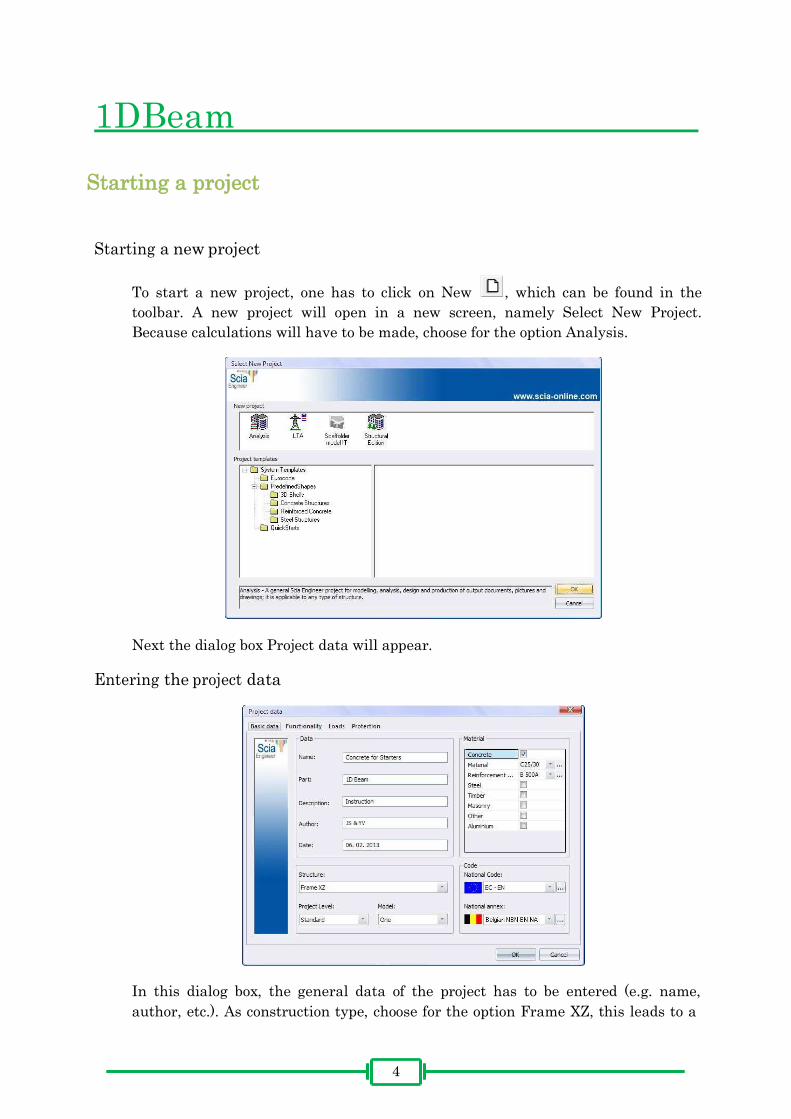
To start a new project, one has to click on New , which can be found in the
toolbar. A new project will open in a new screen, namely Select New Project.
Because calculations will have to be made, choose for the option Analysis.
Next the dialog box Project data will appear.
Entering the project data
In this dialog box, the general data of the project has to be entered (e.g. name,
author, etc.). As construction type, choose for the option Frame XZ, this leads to a

5
structure of which all nodes are fixed. Consequently, the user will be able to
introduce forces on the elements themselves (Truss XZ implies structures with
hinged nodes, where forces can only be applied in these nodes).
Additionally, the user can further specify the used materials. In this example is
opted for Concrete C25/30 and Reinforcement steel, type B 500A.
Finally, the calculations will be executed according to NBN-EN NA. Click on the
OK button to confirm the project data.
Defining the construction
The 1D-beam
To determine the geometry of the structure, double-click on Structure in the Main
menu option.
The selected menu will open. In this project, there is chosen for a 1D beam. This
can be done through the submenu 1D member > Beam.
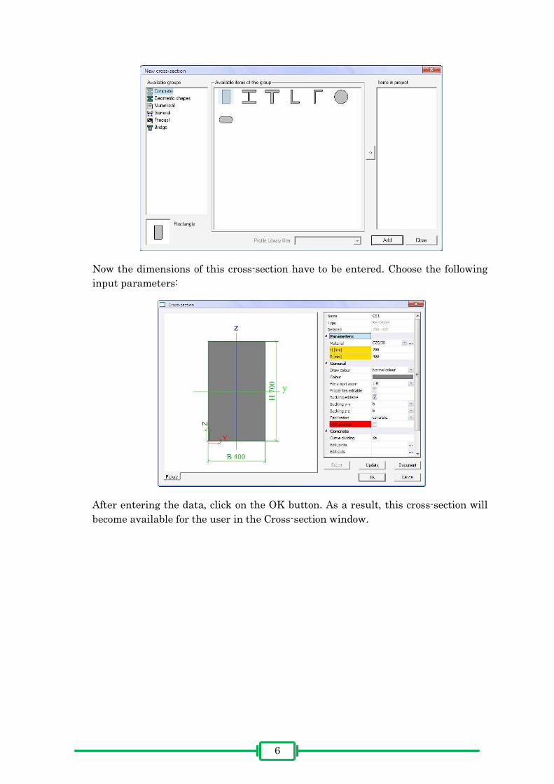
Because there is no section that has been defined yet, the window New cross-
section will open up automatically. The beam in this project has a rectangular
cross-section. To create this cross-section, one has to select Rectangle and click the
Add button.
6
Now the dimensions of this cross-section have to be entered. Choose the following
input parameters:
After entering the data, click on the OK button. As a result, this cross-section will
become available for the user in the Cross-section window.
7
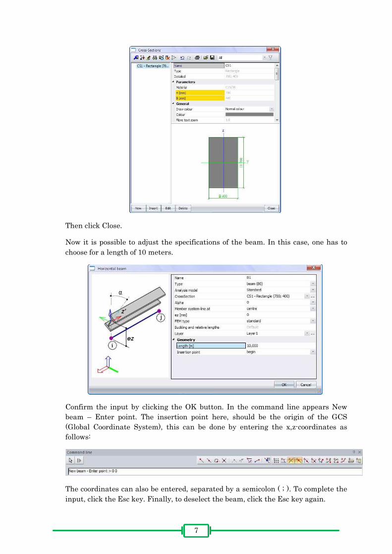
Then click Close.
Now it is possible to adjust the specifications of the beam. In this case, one has to
choose for a length of 10 meters.
Confirm the input by clicking the OK button. In the command line appears New
beam – Enter point. The insertion point here, should be the origin of the GCS
(Global Coordinate System), this can be done by entering the x,z-coordinates as
follows:
The coordinates can also be entered, separated by a semicolon ( ; ). To complete the
input, click the Esc key. Finally, to deselect the beam, click the Esc key again.
8
The beam will be displayed as follows:
Remark: through the button, other cross sections can be defined.
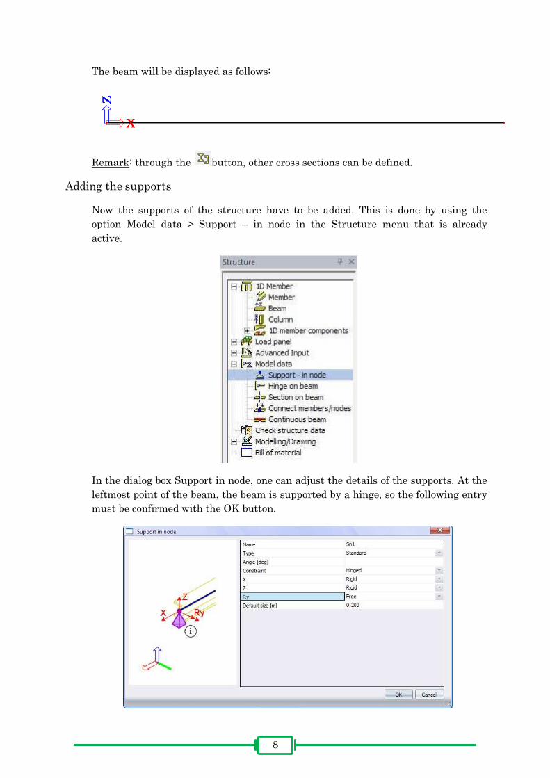
Adding the supports
Now the supports of the structure have to be added. This is done by using the
option Model data > Support – in node in the Structure menu that is already
active.
In the dialog box Support in node, one can adjust the details of the supports. At the
leftmost point of the beam, the beam is supported by a hinge, so the following entry
must be confirmed with the OK button.
9
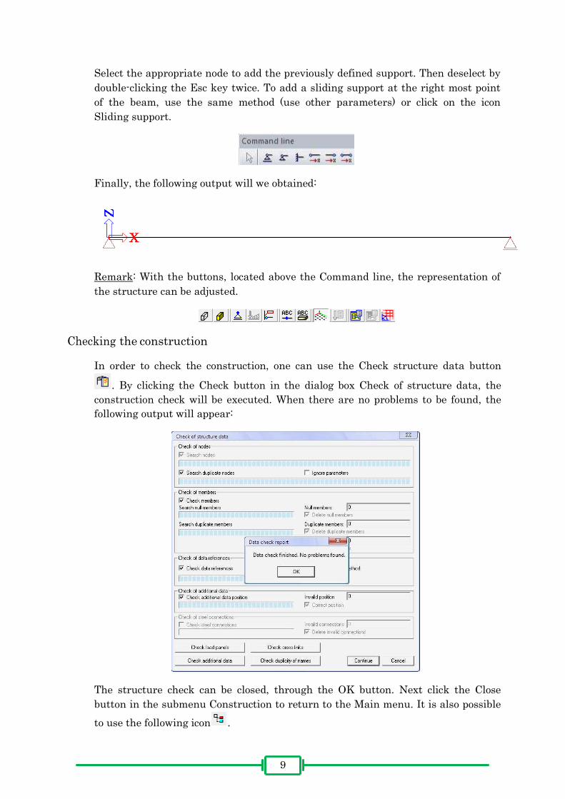
Select the appropriate node to add the previously defined support. Then deselect by
double-clicking the Esc key twice. To add a sliding support at the right most point
of the beam, use the same method (use other parameters) or click on the icon
Sliding support.
Finally, the following output will we obtained:
Remark: With the buttons, located above the Command line, the representation of
the structure can be adjusted.
Checking the construction
In order to check the construction, one can use the Check structure data button
. By clicking the Check button in the dialog box Check of structure data, the
construction check will be executed. When there are no problems to be found, the
following output will appear:
The structure check can be closed, through the OK button. Next click the Close
button in the submenu Construction to return to the Main menu. It is also possible
to use the following icon .

1010
Applying the loads
Creating the load cases
The loads can always be divided into permanent and imposed loads. In this project
there are 3 permanent loads and 1 imposed load, these are:
Permanent loads
Self weight of the beam
Weight of the slab, located on the beam
Weight of the finishing layer
Imposed load
Category B (offices)
To apply the loads, double-click the option Load cases, Combinations in the Main
menu. Because there are no loads yet defined, the dialog box Load cases will open
automatically. Here, the user can define the characteristics of the loads. First enter
the self weight of the beam as follows:
By clicking the New button, the remaining permanent loads can be entered as well.
Be sure to select Standard as Load type, when creating the permanent loads, other
than the self weight. Finally, to add the variable load, insert following parameters.

1111
This example concerns an office (category B), therefore it is necessary to change the
load type by clicking . Choose for the option Cat B: Offices.
Click the OK button to return to the dialog box Load cases. If the necessary loads
are created, one closes the entry by using the Close button.
Remark: Load groups determine the way the individual loads will be combined
with each other, when making load combinations.

1212
Remark: Load cases can be adjusted through the option Load cases, Combinations
< Load Cases.
Applying the loads
The submenu Load will open automatically. Within this menu, all the different
loads can be applied. By clicking , the user can choose the proper load case. Scia
Engineer will automatically calculate the self weight of the structure, therefore no
further attention needs to be spend on this load case. The weight of the slab (LC2 –
Slab) on the beam can be represented as a Line force of 15 kN/m. This can be done
by double-clicking Line force – on beam.

1313
In the dialog box Line force on beam, the following parameters have to be entered:
Note that the value of the load is negative, this is because the load disposes of a
negative sense in the Z-direction. The System is set to LCS (Local Coordinate
System), this means that all parameters are related to the coordinate system of the
structure. Choose Rela as Coord. definition, hereby the values of Position x1 and
Position x2 will be applied, relative to the beam. The value 0,000 for Position x1
will therefore propose the starting point of the beam, the value 1,000 for Position
x2 the endpoint.
After clicking the OK button, one obtains a graphical representation of the applied
load.
In this example, only Line forces occur. This means all loads can be applied as
described above. LC3 – Finishing layer has a value of -6,9 kN/m and LC4 –
Variable load a value of -9 kN/m.
1414
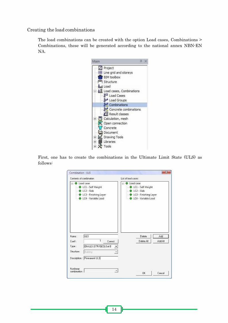
Creating the load combinations
The load combinations can be created with the option Load cases, Combinations >
Combinations, these will be generated according to the national annex NBN-EN
NA.
First, one has to create the combinations in the Ultimate Limit State (ULS) as
follows:

1515
This ULS-combination contains all created loads, one can add this to Contents of
combination through the Add All button. The user also has the possibility to add an
additional Description. Choose the type EN-ULS (STR/GEO) Set B, as this is the
permanent situation without any geotechnical effects. Confirm with the OK button.
Next, a combination for the Serviceability Limit State (SLS) has to be created. This
can be done by clicking the New button en choosing the type EN-SLS Quasi-
permanent.
The created combinations can always be consulted in the dialog box Combinations.
Click the Close button to close this window.
1616
Remark: through the behind Explode to linear in the dialog
box Combinations, all possible linear combinations will be generated from the
selected combination, in order to perform any checkups.
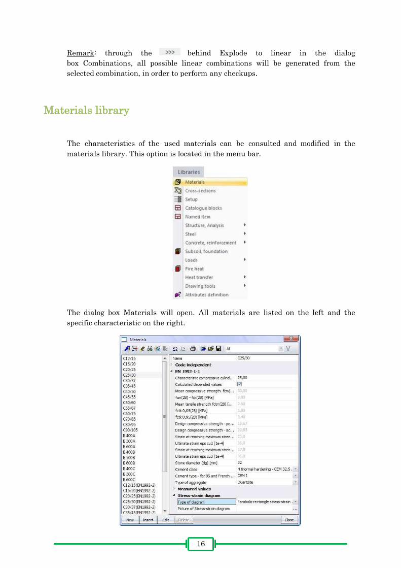
Materials library
The characteristics of the used materials can be consulted and modified in the
materials library. This option is located in the menu bar.
The dialog box Materials will open. All materials are listed on the left and the
specific characteristic on the right.

1717
Any further calculations will be performed according to a parabola-rectangle
stress-strain diagram as Type of diagram for the material C25/30.
Choose also for a Bi-linear without an inclined top branch for steel B 500A. To
obtain a graphical representation, click after Picture of Stress-strain diagram.
Linear calculation
After creating and applying the loads, the construction needs to be calculated. This
is done through . A new dialog box, FE analysis, will appear. Perform a linear
calculation by clicking the OK button.

1818
After performing this linear calculation, Scia Engineer reports the end of the
calculation:
Click the OK button to close this window.

1919
Results
After completing the calculation, the user gains access to the Results menu.
Reaction forces
Through Results > Supports > Reactions, the reaction forces at the supports can be
determined.
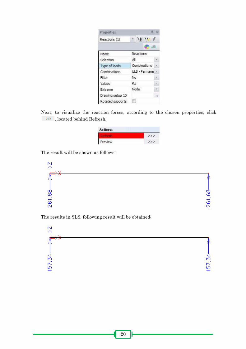
In the Properties window, the user can adjust any settings. To display the reaction
forces in the Z-direction, choose as Values for Rz. Be sure Combinations are set to
ULS-Permanent.
2020
Next, to visualize the reaction forces, according to the chosen properties, click
, located behind Refresh.
The result will be shown as follows:
The results in SLS, following result will be obtained:

2121
Internal forces
Through Results > Beams > Internal forces on beam, the internal forces can be
requested.
In the Properties, the user has to select the appropriate properties:

2222
The results will be visible after clicking , behind Refresh. Following internal
forces will be given, in case of the ULS:
And for the SLS:

2323
Concrete – general
Through the Concrete menu in Main menu, the user has the ability to perform
specific concrete related checkups.
To adjust the properties of a concrete element, consult the option 1D member >
Member data.
The concrete element, of which the properties need to be changed, has to be
selected. This is indicated in the command line.

2424
The dialog box Concrete 1D data will open. After ticking the Advanced mode, the
user can perform several adjustments concerning the characteristics of the selected
element. These adjustments need to be done as follows:
After clicking the OK button, a label will appear next to the concrete member. By
selecting this label, the properties can be consulted or changed.
Remark: the user is also able to change the overall settings of all the different
elements through the Design defaults. However these changes will not affect the
elements that have been provided with member data.

2525
Concrete – theoretical reinforcement
Through the option 1D member > Member design – Design, several aspects of the
theoretical reinforcements can be calculated.
Choose the following options in the properties window:

2626
By choosing As total req. and clicking , Scia Engineer will calculate the
reinforcement that is needed to resist the internal forces [mm²].
By clicking behind Preview, more details will be shown in a table.
Remark: by ticking Print explanation of errors, any errors (E) or warning (W) will
be explained.
Remark: by selecting As user defined or As add. req., respectively the
reinforcement added by the user and the extra reinforcement that is needed will be
given.
2727
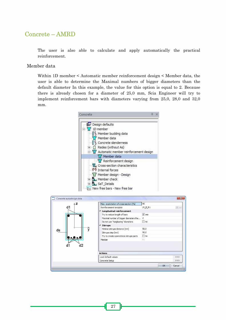
Concrete – AMRD
The user is also able to calculate and apply automatically the practical
reinforcement.
Member data
Within 1D member < Automatic member reinforcement design < Member data, the
user is able to determine the Maximal numbers of bigger diameters than the
default diameter In this example, the value for this option is equal to 2. Because
there is already chosen for a diameter of 25,0 mm, Scia Engineer will try to
implement reinforcement bars with diameters varying from 25,0, 28,0 and 32,0
mm.

2828
After confirming the properties, the selected element will obtain another label.
Reinforcement design
Through 1D member < Automatic member reinforcement design < Reinforcement
design, one can calculate the actual reinforcement, after entering the correct
parameters and confirming these by clicking the Refresh button.
The following output will be displayed:

2929
Remark: It is possible to display the reinforcement bars in a more realistic manner
by changing the properties in the Set view parameters for all option.
More specifically by changing the settings in the Concrete – tab as follows:

3030
y the re n orcement bars w be d sp ayed ke th s
by us ng the o ow ng buttons th
Eventuall , i f ill i l li i :
Remark: i f ll i , e user is
able to change the view or to zoom in and out.
3131
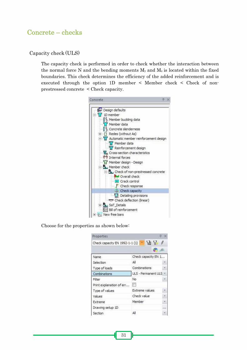
Concrete – checks
Capacity check (ULS)
The capacity check is performed in order to check whether the interaction between
the normal force N and the bending moments My and Mz is located within the fixed
boundaries. This check determines the efficiency of the added reinforcement and is
executed through the option 1D member < Member check < Check of non-
prestressed concrete < Check capacity.
Choose for the properties as shown below:

3232
After refreshing, the output will be as follows:
Remark: the output will be the maximum value, which has to be smaller than 1 in
order to be correct. A correct output will be displayed in green.
The results of each cross section can be observed by clicking , behind Single
Check. The command line will ask the user to select the member of which the cross
section will be analyzed.
Remark: it is necessary to click Calculation, in order to obtain the output as shown
above. The user is also able to choose the exact position of the cross section, as well
as to scroll through the results by using the tabs.

3333
Response check (ULS)
This check is executed in order to make sure the stresses, in both concrete and
reinforcement steel, do not excess their limit values. The check can be performed
through 1D member < Member check < Check of non-prestressed concrete < Check
response.
Select the following settings in the properties window:

3434
After clicking the Refresh button, the following output will be obtained:
The user is also able to request a Preview and to perform a Single Check.
Crack control (SLS)
Scia Engineer also offers the opportunity to check the construction for possible
cracks. This is done with the option 1D member < Member check < Check of non-
prestressed concrete < Crack control.

3535
The properties should be changed as shown below:
Make sure to choose the option Asuser, this value is equal to the previously added
reinforcement during the AMRD. After clicking the Refresh button, the output will
be as follows:
The user is also able to request a Preview and to perform a Single Check.
3636
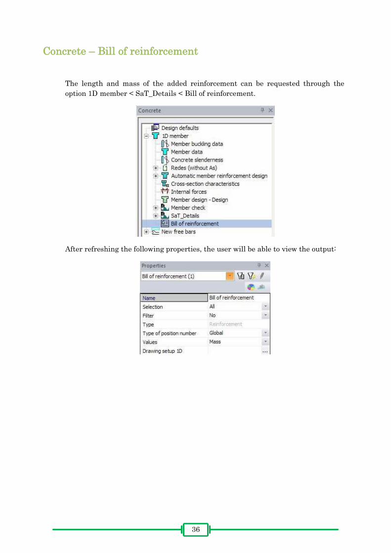
Concrete – Bill of reinforcement
The length and mass of the added reinforcement can be requested through the
option 1D member < SaT_Details < Bill of reinforcement.
After refreshing the following properties, the user will be able to view the output:
3737
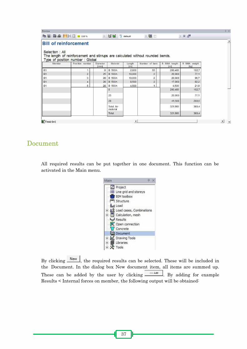
Document
All required results can be put together in one document. This function can be
activated in the Main menu.
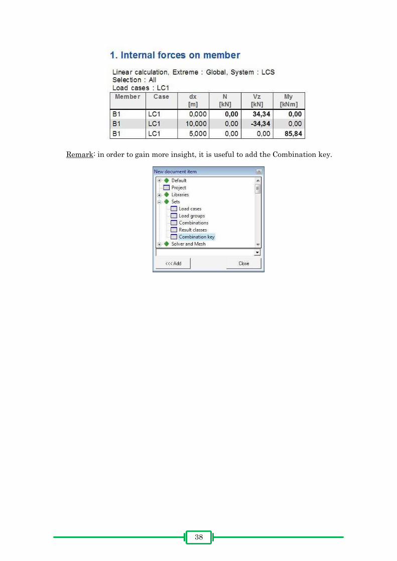
By clicking , the required results can be selected. These will be included in
the Document. In the dialog box New document item, all items are summed up.
These can be added by the user by clicking . By adding for example
Results < Internal forces on member, the following output will be obtained:
38
Remark: in order to gain more insight, it is useful to add the Combination key.