conceptual sewer report - reno, nevada
TRANSCRIPT


CONCEPTUAL SEWER REPORT
JN: 9000.100 Page i July, 2017
TABLE OF CONTENTS I. INTRODUCTION ....................................................................................................... 1
II. SEWER FLOWS ....................................................................................................... 1
A. Sewer Generation Factors ......................................................................................... 1
B. Projected Sewer Flows .............................................................................................. 3
III. DESIGN CRITERIA ................................................................................................ 4
A. Gravity Sewer System ............................................................................................... 4
B. Lift Station ............................................................................................................... 4
C. Sewer Force Main ..................................................................................................... 5
IV. EVALUATION OF SEWER FACILITIES..................................................................... 5
A. Gravity Sewer System ............................................................................................... 5
B. Wet Well Location and Sizing ..................................................................................... 6
C. Sewer Force Main Alignment...................................................................................... 6
D. Pump and Force Main Sizing ...................................................................................... 7
V. CONCEPTUAL SEWER SYSTEM RECOMMENDATIONS .............................................. 8
A. System Description ................................................................................................... 8
B. Opinion of Probable Costs ......................................................................................... 9
C. Permitting Requirements ..........................................................................................10
D. Construction Considerations .....................................................................................10
VI. CONCLUSIONS .....................................................................................................10
VII. REFERENCES ......................................................................................................11
APPENDICES
Appendix A Sewer Generation Calculations
Appendix B Sewer Model Output
Appendix C Preliminary Wet Well Sizing Calculations
Appendix D Preliminary Pump and Force Main Sizing Calculations
CONCEPTUAL SEWER REPORT
JN: 9000.100 Page ii July, 2017
LIST OF TABLES Table 1: Projected Sewer Flows ........................................................................................... 3
Table 2: Preliminary Pipeline Lengths for Backbone Gravity Sewer Network ............................ 6
Table 3: Preliminary Pump and Force Main Sizing Summary ................................................... 7
Table 4: Preliminary Opinion of Probable Project Costs .......................................................... 9
LIST OF FIGURES Figure 1: StoneGate Phasing Map .......................................................................................13
Figure 2: Preliminary Sanitary Sewer Layout ........................................................................14
Figure 3: Preliminary Force Main Alignment .........................................................................15
[File Doc: L:\LAProj\9000.100 - Heinz Ranch Entitlements\Civil\Sewer\0-Reports\Handbook\final_20170720\9000.100 Sewer Report.docx] July 20, 2017

CONCEPTUAL SEWER REPORT
JN: 9000.100 Page 1 July, 2017
I. INTRODUCTION
The StoneGate Planned Unit Development (PUD) is located 12 miles north of the US395-580/I-80 interchange in the Cold Springs area of Reno, Nevada. The Master Developer, Heinz Ranch Land Company, LLC, holds property on the north and south side of US395. Property on the north side of the freeway will be developed into the StoneGate Town Center (TC) and consists of 359 acres encroaching on the following parcels: 087-010-43 and 087-010-46. Property on the south side of the freeway will be developed into the StoneGate Master Planned Community (MPC) and is comprised of 1,378 acres encroaching on the following parcels: 081-010-18, 081-010-13, 081-110-32, and 081-110-33. The StoneGate properties reside within Section 32, T21N, R18E, Section 33, T21N, R18E and Section 5, T20N, R18E, in the City of Reno, Nevada. The proposed StoneGate MPC will consist of 3,935 single-family and 200 multi-family residential units, a 12-acre neighborhood center with retail-commercial space, two elementary schools, and associated open space and parks. The proposed StoneGate TC will consist of approximately 865 multi-family residential units, a high school, and commercial/industrial space. Wastewater generated from StoneGate will be collected through a network of gravity sewer pipelines to an on-site lift station and ultimately conveyed to the Cold Springs Water Reclamation Facility (CSWRF) on Mud Springs Drive, approximately 3.7 miles north of StoneGate. The purpose of this report is to provide preliminary design recommendations for the conceptual on-site and off-site sewer system. Projected sewer flows and design recommendations presented in this report are at the conceptual level based on preliminary development areas, lot counts, and lot sizes. Sewer flows and infrastructure design will be updated as necessary during the final planning stages of each development area. The final sewer flows and design of all infrastructure will ultimately be reviewed by and coordinated with Washoe County prior to the issuance of any will-serves or approvals associated with sewer service for the project.
II. SEWER FLOWS
Preliminary flow projections to be used in designing the on-site and off-site sewer system are described below. A. Sewer Generation Factors
StoneGate is in the City of Reno, but wastewater generated from the project will be collected by a gravity system to an on-site lift station and ultimately conveyed to the CSWRF, operated by the Washoe County Department of Water Resources (WCDWR). City of Reno and Washoe County are planning to enter into an agreement whereby the StoneGate on-site gravity sewer system will be owned and maintained by the WCDWR. For this reason, recommended design criteria for sewer generation and peaking factors are based upon the 2016 WCDWR Gravity Sewer Collection Design Standards (WCDWR Standards) [1] as follows:

CONCEPTUAL SEWER REPORT
JN: 9000.100 Page 2 July, 2017
� Single Family Residential Average Daily Flow (ADF): 270 gallons per day per dwelling unit (gpd/DU)
� Multi-Family Residential ADF: 180 gallons per day per dwelling unit (gpd/DU)* � Neighborhood Commercial ADF: 2,536 gpd/acre (use for StoneGate MPC neighborhood
center and portions of StoneGate TC commercial) � General Commercial ADF: 780 gpd/acre � Industrial ADF: 457 gpd/acre � Gravity System Peaking factor: 3.0 (applied to ADF to establish peak flows for gravity
sewer) � Pressure System Peaking Factor: 2.0 (applied to ADF to establish peak flows for lift station
and force main, as determined during meeting with Washoe County and Farr West on December 7, 2016).
* Multi-family residential flows are 2/3 of single family residential based on occupancy
rates in the City of Reno Public Works Design Manual [2]. In addition, sewer generation for the elementary and high schools were determined based on “Wastewater Engineering: Treatment and Resource Recovery” by Metcalf and Eddy [3] as follows:
� Elementary School ADF: 15 gpd/student (schools with cafeteria only) � High School ADF: 20 gpd/student (schools with cafeteria, gym, and showers)
CONCEPTUAL SEWER REPORT
JN: 9000.100 Page 3 July, 2017
B. Projected Sewer Flows
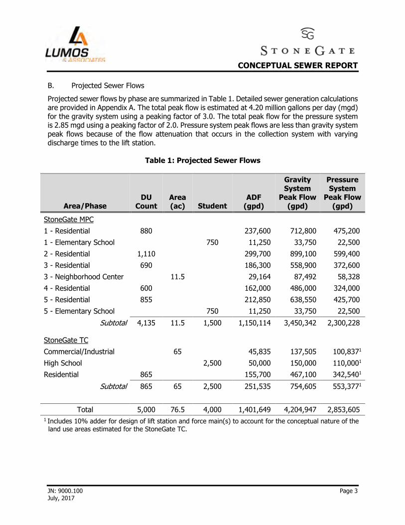
Projected sewer flows by phase are summarized in Table 1. Detailed sewer generation calculations are provided in Appendix A. The total peak flow is estimated at 4.20 million gallons per day (mgd) for the gravity system using a peaking factor of 3.0. The total peak flow for the pressure system is 2.85 mgd using a peaking factor of 2.0. Pressure system peak flows are less than gravity system peak flows because of the flow attenuation that occurs in the collection system with varying discharge times to the lift station.
Table 1: Projected Sewer Flows
Area/Phase DU
Count Area (ac) Student
ADF (gpd)
Gravity System
Peak Flow (gpd)
Pressure System
Peak Flow (gpd)
StoneGate MPC
1 - Residential 880 237,600 712,800 475,200
1 - Elementary School 750 11,250 33,750 22,500
2 - Residential 1,110 299,700 899,100 599,400
3 - Residential 690 186,300 558,900 372,600
3 - Neighborhood Center 11.5 29,164 87,492 58,328
4 - Residential 600 162,000 486,000 324,000
5 - Residential 855 212,850 638,550 425,700
5 - Elementary School 750 11,250 33,750 22,500
Subtotal 4,135 11.5 1,500 1,150,114 3,450,342 2,300,228
StoneGate TC
Commercial/Industrial 65 45,835 137,505 100,8371
High School 2,500 50,000 150,000 110,0001
Residential 865 155,700 467,100 342,5401
Subtotal 865 65 2,500 251,535 754,605 553,3771
Total 5,000 76.5 4,000 1,401,649 4,204,947 2,853,605 1 Includes 10% adder for design of lift station and force main(s) to account for the conceptual nature of the
land use areas estimated for the StoneGate TC.

CONCEPTUAL SEWER REPORT
JN: 9000.100 Page 4 July, 2017
III. DESIGN CRITERIA
A. Gravity Sewer System
As mentioned previously, City of Reno and Washoe County are planning to enter into an agreement whereby the StoneGate on-site gravity sewer system will be owned and maintained by the WCDWR. For this reason, design criteria for the on-site gravity system are based upon the WCDWR Standards [1] as summarized below with any adjustments to the WCDWR Standards shown in italics. In addition to the WCDWR Standards, recommendations in the Ten State Standards will also be considered (e.g. minimum pipeline slopes) [4]. Gravity Pipelines
� Pipe sizing: peak flows for gravity system � Minimum pipeline diameter: 8-inch � Minimum depth of cover for sewer mains: 48-inches � Minimum velocity: 2.5 feet per second (fps) when flowing half full � Maximum velocity: 10 fps � Manning’s roughness coefficient “n”: 0.012 � Pipe material: SDR 35 PVC pipe � Maximum depth of flow (depth/diameter: d/D): 0.8 � Curved sewer design not allowed
Manholes
� Placed at all intersections, angle points, and grade changes � Maximum spacing of 400 feet (ft) on straight line runs � Type and size:
o 48-inch diameter Type 1-A for sewer pipes less than 18-inch diameter at depths less than 18 ft
o 60-inch diameter Type V-A for sewer pipes between 18 to 27-inch diameter at depths greater than 18 ft
o 60-inch diameter Type IV-A for sewer pipes 30-inch diameter and greater � Invert elevation (IE):
o Exit IE should be 0.1 ft below entrance IE(s) for same diameter pipe sizes o Crown elevations should match for pipes of different diameter intersecting at a manhole
B. Lift Station
Recommended design criteria for the on-site lift station based on industry standards are provided below:
� Lift station sizing: peak flows for pressure system � Minimum number of pumps: 2 (1 duty + 1 standby), each designed to pump 100% of peak
flow � Pump type: submersible � Minimum cycle time between pump starts: 6-10 minutes � Filling time of wet well: maximum of 30 minutes per 10 State Standards [4]

CONCEPTUAL SEWER REPORT
JN: 9000.100 Page 5 July, 2017
� Wet well cross-section: to be determined
C. Sewer Force Main
Recommended design criteria for the off-site sewer force main based on industry standards are provided below:
� Force main sizing: peak flow for pressure system � Minimum depth of cover: 48-inches � Velocity: 2-6 fps � Pipe material: PVC, HDPE, or ductile iron � Hazen-Williams roughness coefficient, “C”: 130-140 depending on material � Assumed discharge elevation at CSWRF: 5,085.8 ft (ground elevation at existing manhole
upstream of CSWRF)
IV. EVALUATION OF SEWER FACILITIES
A. Gravity Sewer System
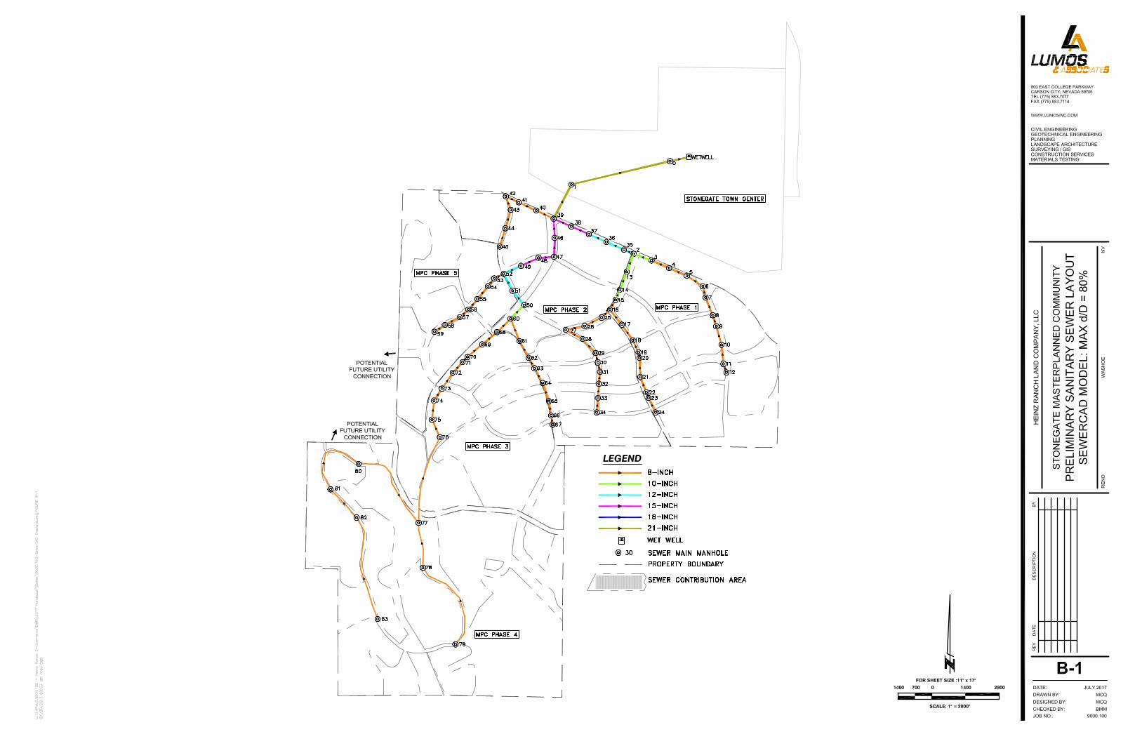
The backbone gravity sewer network was designed given preliminary road alignments and finish grades within the StoneGate community. To size the gravity sewer pipelines, the conceptual network was modeled using Bentley SewerCAD software. Input to the sewer model included physical data (pipe lengths, alignments, and grade elevations) and sanitary loads (peak flows) for each sewer contribution area. The model generated minimum required pipeline sizes and slopes using the design criteria outlined in Section III.A (roughness coefficients, maximum depth of flow, minimum velocities, and minimum depths of cover). The preliminary, on-site, gravity sewer network is presented in Figure 2 with corresponding tables of pipeline velocities, slopes, and depths of flow. In addition, sewer model output is provided in Appendix B. The gravity sewer system will be phased to match the growth of the development.

CONCEPTUAL SEWER REPORT
JN: 9000.100 Page 6 July, 2017
Total preliminary pipeline lengths for the backbone gravity sewer network are summarized in Table 2. Additional collection mains are part of the project, however, with the flexible nature of each village in the StoneGate MPC and the development in the StoneGate TC, these quantities are difficult to determine and are not included in the pipe lengths shown in Table 2.
Table 2: Preliminary Pipeline Lengths for Backbone Gravity Sewer Network
Pipe Size Pipe Length1
(LF)
8-inch 29,880
10-inch 1,830
12-inch 2,200
15-inch 2,325
21-inch 3,315
Total 39,550
1 Preliminary quantities for backbone collection system only.
B. Wet Well Location and Sizing
The preliminary location for the on-site lift station is within the StoneGate TC boundary as shown on Figures 2 and 3. Because the proposed lift station may be located near or within the 100-year flood zone, the top of the structure and electrical components will be built above the 100-year flood elevation to mitigate flooding hazards as required by Nevada Division of Environmental Protection (NDEP). The lift station will be sized to handle buildout flows from the StoneGate MPC and TC. Sizing of the lift station wet well is a factor of the minimum cycle time between pump starts, reserve volume, minimum pump submergence, pump spacing requirements, and the IEs of incoming gravity sewer pipelines. Using a 10 ft square (or similar sized rectangular) wet well with 6-8 minutes between pump starts (7-10 starts per hour), a reserve volume of 0.5-1.0 ft, and a minimum pump submergence of 3.0 ft, the total wet well depth required would be approximately 21 ft, but could range from 20-25 ft. Wet well dimensions need to be confirmed during design and coordinated with the pump manufacturer (e.g. minimum spacing requirements between pumps could result in larger wet well). Preliminary wet well sizing calculations are included in Appendix C. Ultimate sizing for emergency conditions or backup power/pumping will be coordinated with Washoe County prior to final design. C. Sewer Force Main Alignment
Wastewater collected at the on-site lift station will be pumped to the CSWRF via force main for a distance of approximately 3.7 miles. The preliminary force main alignment is presented in Figure 3 and described below:

CONCEPTUAL SEWER REPORT
JN: 9000.100 Page 7 July, 2017
� Preliminary Alignment: Force main travels along the east side of White Lake through the
following parcels: APN 087-010-43 (owned by Heinz Ranch Land Company), 087-010-41, 087-382-01, and 087-032-02. Force main then travels north along right-of-way for Village Pkwy. and within an existing utility/access easement in Mud Springs Dr. for a total distance of approximately 19,400 LF.
The preliminary force main alignment is the shortest length around White Lake, minimizes encroachment on public right-of-way with use of the StoneGate TC property north of US395, and crosses only one other private property owner. D. Pump and Force Main Sizing
Preliminary pump and force main sizing calculations were performed using total pressure system peak flows anticipated for the development with a 10% adder to the StoneGate TC flows to account for the conceptual nature of the estimated land use areas. Assumptions used for sizing of the pumps and force mains include a total buildout flow of 2.85 mgd or 1,990 gallons per minute (gpm), an estimated wet well depth of 21 ft, and a force main length of 19,400 LF. System curves were generated for various combinations of force main diameters and compared with pump curves. Based on the analysis, a total of (3) 10-inch force mains are initially proposed with 3-4 submersible pumps (2-3 duty pumps + 1 standby). The advantage of multiple force mains and duty pumps is to provide operational flexibility in handling a range of sewer flows as each phase is developed. A preliminary pump and force main sizing summary is presented in Table 3. Detailed calculations and preliminary system/pump curves are included in Appendix D. Further variations of the lift station pump arrangement may also be evaluated during the final design to ensure the most efficient and economical pump arrangement.
Table 3: Preliminary Pump and Force Main Sizing Summary
No. Force Mains & Diameter
(inch)
Peak Flow
(gpm) Velocity
(fps)
Friction Loss (ft)
TDH1
(ft) No. Pumps
Required Motor
Size (hp)
(3) 10” 1,990 2.7 49 113 2-3 duty + 1 standby
50-100 each
1 TDH = Total Dynamic Head.
Because the StoneGate community will be developed in phases, initial sewer flows will be significantly lower than total flows projected at full build out. To avoid oversized pumps/wet well and high operating costs for initial sewer flows, a smaller initial pumping system and/or an interim lift station is being considered. An upstream manhole could be used as an interim lift station in conjunction with smaller pump(s), or the lift station wet well could be partitioned to optimize time between pump starts. Additional smaller diameter force mains (e.g. 4 to 6-inch diameter) may be included to handle the low flows associated with the initial phases of development.

CONCEPTUAL SEWER REPORT
JN: 9000.100 Page 8 July, 2017
V. CONCEPTUAL SEWER SYSTEM RECOMMENDATIONS
A. System Description
The on-site backbone sewer system will consist of approximately 7.5 miles of gravity sewer pipeline ranging from 8-inch to 21-inch diameter. Buildout peak flows for the gravity system are estimated at 4.20 mgd. Wastewater will be conveyed to a single on-site lift station designed for a total pressure system peak flow of 2.85 mgd. Preliminary options for the lift station include a square or rectangular wet well with a total depth of 20-25 ft. Final wet well dimensions and shape will be determined during design. A triplex pump system (2 duty + 1 standby) or 4-pump system (3 duty + 1 standby) is currently being proposed, with preliminary motor sizes ranging from 50 to 100 horsepower (hp) each. There is potential that StoneGate MPC Phase 1 could be served by a separate gravity main under US395 independent of the gravity system severing Phases 2-5. For Phase 1, total peak flows are estimated at 0.75 mgd. These flows could be conveyed by a smaller diameter gravity pipeline that is jack and bored under US395 to the lift station (or to an upstream manhole used as an interim lift station). A larger diameter gravity main would be required to convey flows from Phases 2-5 under US395 and could be planned and timed in conjunction with other major infrastructure crossing the highway. The initial gravity sewer main for Phase 1 would be located approximately 1/3 mile east of the proposed highway crossing shown in Figure 2. Upon construction of sewer infrastructure for Phases 2-5, the initial gravity main could continue to operate independently or flows could be redirected through Phase 2 gravity pipelines to the main highway crossing location. The final sewer system layout and crossings under US395 will be coordinated with Washoe County and other permitting agencies prior to final design. The preliminary off-site sewer system includes (3) 10-inch force mains approximately 19,400 LF in length each. Additional smaller diameter force mains may be included to handle low flows associated with the initial phases of development. The preliminary force main alignment travels from the proposed lift station located within the StoneGate TC, along the east side of White Lake through private property, then north to the CSWRF within right-of-way for Village Pkwy.

CONCEPTUAL SEWER REPORT
JN: 9000.100 Page 9 July, 2017
B. Opinion of Probable Costs
A preliminary opinion of probable project costs for the preliminary on-site and off-site sewer facilities is presented in Table 4.
Table 4: Preliminary Opinion of Probable Project Costs
Item Description Unit Quantity Unit Cost Total Cost
On-Site Sewer 1 Mobilization and Demobilization LS 1 $ 120,000 $ 120,000
2 8-inch Gravity Pipeline1 LF 29,880 $ 40 $ 1,195,200
3 10-inch Gravity Pipeline1 LF 1,830 $ 45 $ 82,350
4 12-inch Gravity Pipeline1 LF 2,200 $ 50 $ 110,000
5 15-inch Gravity Pipeline1 LF 2,325 $ 60 $ 139,500
6 21-inch Gravity Pipeline1 LF 3,315 $ 70 $ 232,050
7 Manholes EA 111 $ 3,500 $ 388,500
8 On-Site Lift Station LS 1 $ 1,300,000 $ 1,300,000
9 Submersible Pumps, Electrical, and Controls
LS 1 $ 450,000 $ 450,000
Subtotal $ 4,017,600
Off-Site Sewer 10 Mobilization and Demobilization LS 1 $ 150,000 $ 150,000
11 Force Main2 LF 19,400 $ 130 $ 2,522,000
12 Connection at CSWRF LS 1 $ 40,000 $ 40,000
13 Air/Vacuum Valves EA 7 $ 20,000 $ 140,000
Subtotal $ 2,852,000
Subtotal On-Site and Off-Site Sewer $ 6,869,600
Contingency (15%) $ 1,030,400
Total Construction Costs $ 7,900,000
Permitting and Environmental $ 30,000
Engineering, Survey, Testing, Inspection, and Other (12%) $ 950,000
Total Project Costs $ 8,880,000 1 Quantities are for backbone collection system only. Includes fittings, excavation, backfill, restoration to
finish grade, connection to structures.
2 Includes restrained joints, fittings, excavation, backfill, restoration to finish grade/pavement replacement, traffic control.
CONCEPTUAL SEWER REPORT
JN: 9000.100 Page 10 July, 2017
C. Permitting Requirements
Permits and approvals that may be required for construction of the on-site and off-site sewer system will include, but not be limited to, the following:
� Washoe County Encroachment Permit � Nevada Department of Transportation (NDOT) Right-of-Way Occupancy Permit � Approvals from Washoe County and City of Reno � NDEP or Washoe County Health
D. Construction Considerations
Considerations for design and construction of the on-site and off-site sewer system are summarized below:
� Phasing: Sewer infrastructure will be phased to match the growth of the development, with the lift station and off-site infrastructure planned for construction with the initial phase. An interim lift station (e.g., an upstream manhole) maybe be used to handle initial flows from StoneGate MPC Phase 1 and the high school.
� Easements: Utility easements will need to be obtained for any portions of the force main alignment through private property.
� Utility conflicts: A thorough investigation of existing utilities along the force main alignment will need to be conducted during design including review of record drawings, coordination with utility companies, and potentially potholing.
� Connection at CSWRF: Available capacity and discharge location at the CSWRF will need to be coordinated with Washoe County.
� Traffic control: Traffic control measures will need to be developed and implemented in accordance with the requirements of Washoe County, NDOT, and the Manual on Uniform Traffic Control Devices.
� NDOT: Construction requirements and right-of-way occupancy permit terms will need to be incorporated into the design and considered for the project schedule.
VI. CONCLUSIONS
Wastewater generated from Phases 1 through 5 of the StoneGate MPC and from the StoneGate TC will be collected by a gravity sewer network and conveyed to a single on-site lift station, located within the StoneGate TC. From the on-site lift station, wastewater will be conveyed to CSWRF, approximately 3.7 miles north of StoneGate, via (3) 10-inch force mains routed along the east side of White Lake. Sewer infrastructure will be phased to match the growth of the development, with the lift station (or interim lift station) and off-site infrastructure planned for construction with initial phases. The final layout and sizing of sewer infrastructure will be determined during final design.

CONCEPTUAL SEWER REPORT
JN: 9000.100 Page 11 July, 2017
VII. REFERENCES
[1] Washoe County Community Services Department, Gravity Sewer Collection Design Standards, March 2016. <https://www.washoecounty.us/csd/engineering_capitalprojects/files-engineering-capital-projects/development_review_forms/CSD%202017%20Sewer%20Design%20Standards.pdf>
[2] City of Reno, Public Works Design Manual, January 2009.
<http://www.reno.gov/home/showdocument?id=58638>
[3] Metcalf & Eddy, Wastewater Engineering: Treatment and Resource Recovery, 2014. [4] Great Lakes-Upper Mississippi River Board of State and Provincial Public Health and
Environmental Managers, Recommended Standards for Wastewater Facilities (10 State Standards), Health Research, Inc., 2014.

FIGURES

Image courtesy of USGS Image courtesy of the Nevada State Mapping Advisory Committee Earthstar Geographics SIO © 2016 Microsoft Corporation
Image courtesy of USGS Image courtesy of the Nevada State Mapping Advisory Committee Earthstar Geographics SIO © 2016 Microsoft Corporation
Image courtesy of USGS Image courtesy of the Nevada State Mapping Advisory Committee Earthstar Geographics SIO © 2016 Microsoft Corporation
SF - 880 DUES - 750 ST
SF - 690 DUNC - 12 AC
SF - 600 DU
SF - 855 DUES - 750 ST
Town CenterHS - 2,500 ST
C/I - 65 ACMF- 865 DU
SF - 1110 DUSF - 1110 DU
Town CenterHS - 2,500 ST
C/I - 65 ACMF- 865 DU
SF - 600 DU
SF - 690 DUNC - 12 AC
SF - 880 DUES - 750 ST
SF - 855 DUES - 750 ST
ABBREVIATIONSC/I COMMERCIAL/INDUSTRIALES ELEMENTARY SCHOOLHS HIGH SCHOOLMF MULIT-FAMILY RESIDENTIALMPC MASTER PLANNED COMMUNITYNC NEIGHBORHOOD COMMERCIALSF SINGLE FAMILY RESIDENTIAL
AC ACRESDU DWELLING UNITSST STUDENTS
MPCPhase 1
MPCPhase 2
MPCPhase 3
MPCPhase 4
MPCPhase 5
MPCPhase 1
MPCPhase 2
MPCPhase 3
MPCPhase 4
MPCPhase 5
Job No:
FIGURE
Scale:
Date:HEINZ RANCH LAND COMPANY, LLC
STONEGATE MASTER PLANNED COMMUNITYSTONEGATE PHASING MAP 9000.100
1
NTS
JULY 2017
9222 PROTOTYPE DRIVERENO, NEVADA 89521
PH. (775) 827-6111 FAX (775) 827-6122 RENO NEVADAWASHOE


APPENDICES

Appendix A
Sewer Generation Calculations

SEWER GENERATION CALCULATIONS
AVG. DAILY FLOW
RATE UNITS
GRAVITY SYSTEM
PEAKING FACTOR
PRESSURE SYSTEM
PEAKING FACTOR ***
270 GAL/DU/DAY
180 GAL/DU/DAY
780 GAL/AC/DAY
2,536 GAL/AC/DAY
664 GAL/AC/DAY
457 GAL/AC/DAY
15 GAL/STUDENT/DAY
20 GAL/STUDENT/DAY
SEWER AREA ID
PERCENTAGE OF DU
CONTRIBUTING TO
SEWER AREA # OF DU
CONTRIBUTING # OF
DU TO SEWER AREA OCCUPANCY TYPE AREA/ STUDENTS
AVG. DAILY
FLOW
GRAVITY
SYSTEM PEAK
FLOW
PRESSURE
SYSTEM PEAK
FLOW
[%] [QUANTITY] [QUANTITY][AC]/
[# STUDENTS][MGD] [MGD] [MGD]
STONEGATE MASTERPLANNED COMMUNITY (SG MPC)PHASE 1
1A 100 120 120 SF 0.032 0.097 0.065
1B 100 120 120 SF 0.032 0.097 0.065
1C 100 200 200 SF 0.054 0.162 0.108
1D 100 125 125 SF 0.034 0.101 0.068
1E 100 47 47 SF 0.013 0.038 0.025
1F 100 150 150 SF 0.041 0.122 0.081
1G - - - Elem School 750 0.011 0.034 0.023
1H 100 80 80 SF 0.022 0.065 0.043
1I 100 38 38 SF 0.010 0.031 0.021
PHASE 1 TOTAL 880 0.249 0.747 0.498
PHASE 2
2A 100 140 140 SF 0.038 0.113 0.076
2B 100 220 220 SF 0.059 0.178 0.119
2C 100 70 70 SF 0.019 0.057 0.038
2D 100 80 80 SF 0.022 0.065 0.043
2E 100 55 55 SF 0.015 0.045 0.030
2F 100 110 110 SF 0.030 0.089 0.059
2G 100 105 105 SF 0.028 0.085 0.057
2H 100 105 105 SF 0.028 0.085 0.057
2I 100 45 45 SF 0.012 0.036 0.024
2K 100 65 65 SF 0.018 0.053 0.035
2L 100 70 70 SF 0.019 0.057 0.038
2M 100 45 45 SF 0.012 0.036 0.024
PHASE 2 TOTAL 1110 0.300 0.899 0.599
PHASE 3
3A 100 120 120 SF 0.032 0.097 0.065
3B 100 95 95 SF 0.026 0.077 0.051
3C 100 110 110 SF 0.030 0.089 0.059
3D - - - NC 11.5 0.029 0.087 0.058
3E 100 75 75 SF 0.020 0.061 0.041
3F 100 255 255 SF 0.069 0.207 0.138
3G 100 35 35 SF 0.009 0.028 0.019
PHASE 3 TOTAL 690 0.215 0.646 0.431
PHASE 4
4A 100 220 220 SF 0.059 0.178 0.119
4D 100 105 105 SF 0.028 0.085 0.057
4E 100 10 10 SF 0.003 0.008 0.005
4G 100 15 15 SF 0.004 0.012 0.008
4H 100 70 70 SF 0.019 0.057 0.038
4I 100 160 160 SF 0.043 0.130 0.086
4J 100 20 20 SF 0.005 0.016 0.011
PHASE 4 TOTAL 600 0.162 0.486 0.324
2PARKS AND OPEN SPACE*
HIGH SCHOOL**
ELEMENTARY SCHOOL**
INDUSTRIAL*
3
PROPERTY TYPERESIDENTIAL (SINGLE FAMILY)*
RESIDENTIAL (MULTI-FAMILY)
GENERAL COMMERCIAL*
NEIGHBORHOOD COMMERCIAL*
L:\LAProj\9000.100 - Heinz Ranch Entitlements\Civil\SEWER\Stone Gate Preliminary Sewer Generation.xlsx

SEWER GENERATION CALCULATIONS
SEWER AREA ID
PERCENTAGE OF DU
CONTRIBUTING TO
SEWER AREA # OF DU
CONTRIBUTING # OF
DU TO SEWER AREA OCCUPANCY TYPE AREA/ STUDENTS
AVG. DAILY
FLOW
GRAVITY
SYSTEM PEAK
FLOW
PRESSURE
SYSTEM PEAK
FLOW
[%] [QUANTITY] [QUANTITY][AC]/
[# STUDENTS][MGD] [MGD] [MGD]
PHASE 5
100 200 200 SF 0.054 0.162 0.108
100 200 200 MF 0.036 0.108 0.072
5B 100 61 61 SF 0.016 0.049 0.033
5C 100 120 120 SF 0.032 0.097 0.065
5D 100 114 114 SF 0.031 0.092 0.062
5E - - - Elem School 750 0.011 0.034 0.023
5F 100 160 160 SF 0.043 0.130 0.086
PHASE 5 TOTAL 855 0.224 0.672 0.448
STONEGATE TOWN CENTER (SG TC)Industrial - - - Industrial 35 0.016 0.048 0.032
Mini Storage† - - - GC 1 0.001 0.002 0.002
Office - - - GC 10 0.008 0.023 0.016
Retail - - - GC 10 0.008 0.023 0.016
Restaurant - - - NC 1 0.003 0.008 0.005
Super Market - - - NC 4 0.010 0.030 0.020
Residential 100 865 865 MF 0.156 0.467 0.311
School - - - High School 2500 0.050 0.150 0.100
Fire Station† - - - GC 1 0.001 0.002 0.002
SG TC TOTAL 865 0.252 0.755 0.503
PROJECT TOTALS # OF DU ACREAGE STUDENTS
AVG. DAILY
FLOW
GRAVITY
SYSTEM PEAK
FLOW
PRESSURE
SYSTEM PEAK
FLOW
SF 3935 1.062 3.187 2.125
MF 1065 0.192 0.575 0.383
NON RESIDENTIAL 73.5 4000 0.147 0.442 0.295
GRAND TOTAL 5000 74 4000 1.402 4.205 2.803
AVG. = AVERAGE
DU = DWELLING UNITS
AC = ACRES
GAL = GALLONS
MGD = MILLION GALLONS PER DAY
MF = MULTI-FAMILY
SF = SINGLE FAMILY
ELEM = ELEMENTARY
*
**
***
†
5A
THE WASHOE COUNTY GRAVITY SEWER COLLECTION DESIGN STANDARDS ARE REFERENCED FOR THE RESIDENTIAL, GENERAL COMMERCIAL, NEIGHBORHOOD
COMMERCIAL, PARKS/OPEN SPACE, AND INDUSTRIAL PROPERTY TYPES' AVERAGE DAILY FLOW SEWER GENERATION VALUES.
IT IS ASSUMED THAT A MAXIMUM OF 1 ACRE OF THE MINI STORAGE AND FIRE STATION WILL HAVE SEWER CONTRIBUTION, IN THE FORM OF OFFICES OR LIVABLE
SPACE.
WASTEWATER ENGINEERING: TREATMENT AND RESOURCE RECOVERY, BY METCALF & EDDY IS REFERENCED FOR THE ELEMENTARY SCHOOL AND HIGH SCHOOL
PROPERTY TYPE'S AVERAGE DAILY FLOW SEWER GENERATION VALUE. (HOWEVER, A MEMO FROM ODYSSEY DATED 12/20/16 CALLS FOR 2,700 GALS/DAY FOR 745
ELEMENTARY STUDENTS, OR APPROX. 3.6 GAL/STUDENT/DAY)
PEAKING FACTOR OF 2 FOR LIFT STATION & FORCE MAINS WAS DETERMINED BY WASHOE COUNTY & FARR WEST IN MEETING, DATED 12-7-16.
L:\LAProj\9000.100 - Heinz Ranch Entitlements\Civil\SEWER\Stone Gate Preliminary Sewer Generation.xlsx

Appendix B
Sewer Model Output

APPENDIX B-2
STONEGATE MASTER PLANNED COMMUNITY
SEWERCAD OUTPUT: WET WELL IN STONEGATE TOWN CENTER
GRAVITY SEWER PIPELINES - MAX d/D of 80%
Label
Start
Node
Invert
(Start) (ft)
Stop
Node
Invert
(Stop) (ft)
Length
(Scaled) (ft) Material
Manning's
n Size
Slope
(Calculated)
(ft/ft)
Flow
(gal/day)
Velocity
(ft/s)
Capacity
(Full Flow)
(gal/day)
Depth
(Normal)
(ft)
d/D: Depth
(Normal) /
Rise (%)
Depth of
Cover
(Start) (ft)
Depth of
Cover
(Stop) (ft)
Elevation
Ground
(Start) (ft)
Elevation
Ground
(Stop) (ft)
Headloss
(ft)
0-WW 0 5,029.39 WW 5,028.59 400 PVC 0.012 21 inch 0.0020 4,204,947 3.58 4,961,392 1.24 70.7 9.5 9.8 5040.64 5040.1 1.10
1-0 1 5,033.62 0 5,029.40 2,113 PVC 0.012 21 inch 0.0020 3,450,342 3.45 4,958,295 1.07 61.4 9.0 9.5 5044.40 5040.6 4.07
2-35 2 5,044.07 35 5,043.42 218 PVC 0.012 12 inch 0.0030 1,147,500 3.02 1,366,270 0.70 70.2 4.5 5.1 5049.55 5049.6 0.75
3-2 3 5,045.39 2 5,044.17 400 PVC 0.012 10 inch 0.0031 495,720 2.50 848,378 0.46 54.9 4.0 4.5 5050.23 5049.6 1.08
4-3 4 5,047.21 3 5,045.49 400 PVC 0.012 8 inch 0.0043 495,720 2.78 554,258 0.49 73.8 4.1 4.1 5051.98 5050.2 1.79
5-4 5 5,051.40 4 5,047.31 400 PVC 0.012 8 inch 0.0102 333,720 3.56 855,009 0.29 43.4 4.1 4.0 5056.16 5052.0 4.03
6-5 6 5,059.35 5 5,051.50 400 PVC 0.012 8 inch 0.0196 333,720 4.51 1,185,541 0.24 36.3 4.1 4.0 5064.12 5056.2 7.95
7-6 7 5,064.15 6 5,059.45 241 PVC 0.012 8 inch 0.0196 333,720 4.50 1,183,180 0.24 36.4 4.1 4.0 5068.92 5064.1 4.80
8-7 8 5,073.32 7 5,064.25 400 PVC 0.012 8 inch 0.0227 236,520 4.31 1,273,662 0.19 29.2 4.1 4.0 5078.09 5068.9 9.15
9-8 9 5,080.92 8 5,073.42 240 PVC 0.012 8 inch 0.0313 135,270 4.12 1,495,854 0.14 20.3 4.1 4.0 5085.68 5078.1 7.57
10-9 10 5,091.60 9 5,081.02 400 PVC 0.012 8 inch 0.0265 135,270 3.88 1,376,499 0.14 21.2 4.1 4.0 5096.37 5085.7 10.66
11-10 11 5,107.90 10 5,091.70 400 PVC 0.012 8 inch 0.0405 135,270 4.52 1,702,337 0.13 19.0 4.1 4.0 5112.67 5096.4 16.28
12-11 12 5,117.48 11 5,108.00 188 PVC 0.012 8 inch 0.0504 97,200 4.42 1,898,952 0.10 15.4 4.0 4.0 5122.15 5112.7 9.56
13-2 13 5,049.47 2 5,044.17 400 PVC 0.012 10 inch 0.0133 651,780 4.63 1,766,579 0.35 42.0 4.1 4.5 5054.41 5049.6 5.15
14-13 14 5,055.93 13 5,049.57 400 PVC 0.012 10 inch 0.0159 651,780 4.94 1,933,264 0.33 40.0 12.9 4.0 5069.65 5054.4 6.47
15-14 15 5,056.72 14 5,056.03 231 PVC 0.012 10 inch 0.0030 651,780 2.63 840,208 0.55 66.2 4.0 12.8 5061.55 5069.7 0.80
16-15 16 5,060.66 15 5,056.82 231 PVC 0.012 8 inch 0.0166 618,030 4.99 1,090,950 0.36 53.9 4.9 4.1 5066.20 5061.6 3.95
17-16 17 5,062.38 16 5,060.76 400 PVC 0.012 8 inch 0.0040 326,430 2.50 538,312 0.37 56.2 4.1 4.8 5067.15 5066.2 1.63
18-17 18 5,069.50 17 5,062.48 400 PVC 0.012 8 inch 0.0175 326,430 4.31 1,120,278 0.25 36.9 4.1 4.0 5074.26 5067.2 7.10
19-18 19 5,074.67 18 5,069.60 279 PVC 0.012 8 inch 0.0182 326,430 4.37 1,140,586 0.24 36.6 4.1 4.0 5079.43 5074.3 5.16
20-19 20 5,077.49 19 5,074.77 116 PVC 0.012 8 inch 0.0235 196,830 4.15 1,296,691 0.18 26.3 4.1 4.0 5082.26 5079.4 2.81
21-20 21 5,088.43 20 5,077.59 400 PVC 0.012 8 inch 0.0271 196,830 4.36 1,392,007 0.17 25.4 4.1 4.0 5093.20 5082.3 10.92
22-21 22 5,102.49 21 5,088.53 340 PVC 0.012 8 inch 0.0411 196,830 5.05 1,714,180 0.15 22.9 4.1 4.0 5107.25 5093.2 14.06
23-22 23 5,108.14 22 5,102.59 127 PVC 0.012 8 inch 0.0438 152,280 4.80 1,771,371 0.13 19.8 4.1 4.0 5112.90 5107.3 5.64
24-23 24 5,121.54 23 5,108.24 333 PVC 0.012 8 inch 0.0399 121,500 4.35 1,689,973 0.12 18.2 4.0 4.0 5126.20 5112.9 13.38
25-16 25 5,067.45 16 5,060.76 238 PVC 0.012 8 inch 0.0281 291,600 4.94 1,417,286 0.21 30.8 4.1 4.8 5072.22 5066.2 6.64
26-25 26 5,070.94 25 5,067.55 400 PVC 0.012 8 inch 0.0085 234,900 3.02 778,525 0.25 37.7 4.1 4.0 5075.71 5072.2 3.42
27-26 27 5,077.41 26 5,071.04 400 PVC 0.012 8 inch 0.0159 234,900 3.79 1,067,358 0.21 31.9 15.6 4.0 5093.70 5075.7 6.43
28-27 28 5,079.52 27 5,077.51 400 PVC 0.012 8 inch 0.0050 234,900 2.50 600,369 0.29 43.4 6.0 15.5 5086.15 5093.7 2.02
29-28 29 5,082.06 28 5,079.62 400 PVC 0.012 8 inch 0.0061 182,250 2.50 661,054 0.24 35.9 4.1 5.9 5086.83 5086.2 2.45
30-29 30 5,084.77 29 5,082.16 200 PVC 0.012 8 inch 0.0131 182,250 3.29 966,564 0.20 29.4 4.1 4.0 5089.54 5086.8 2.66
31-30 31 5,090.03 30 5,084.87 200 PVC 0.012 8 inch 0.0258 125,550 3.76 1,358,679 0.14 20.5 4.1 4.0 5094.80 5089.5 5.22
32-31 32 5,105.11 31 5,090.13 250 PVC 0.012 8 inch 0.0599 125,550 5.07 2,071,368 0.11 16.7 4.1 4.0 5109.88 5094.8 15.08
33-32 33 5,112.25 32 5,105.21 300 PVC 0.012 8 inch 0.0235 125,550 3.64 1,296,072 0.14 21.0 4.1 4.0 5117.02 5109.9 7.10
34-33 34 5,127.44 33 5,112.35 300 PVC 0.012 8 inch 0.0503 89,100 4.30 1,897,219 0.10 14.8 4.0 4.0 5132.11 5117.0 15.16
35-36 35 5,043.32 36 5,042.12 400 PVC 0.012 12 inch 0.0030 1,147,500 3.02 1,366,270 0.70 70.2 5.3 6.5 5049.57 5049.6 1.30
36-37 36 5,042.02 37 5,040.82 400 PVC 0.012 12 inch 0.0030 1,147,500 3.02 1,366,270 0.70 70.2 6.6 7.8 5049.61 5049.7 1.33
37-38 37 5,040.72 38 5,039.52 400 PVC 0.012 15 inch 0.0030 1,260,900 3.14 2,477,213 0.63 50.5 7.7 8.9 5049.65 5049.7 1.28
38-39 38 5,039.42 39 5,035.82 400 PVC 0.012 15 inch 0.0090 1,260,900 4.70 4,287,941 0.46 37.1 9.0 12.6 5049.67 5049.7 3.58
39-1 39 5,035.32 1 5,033.72 800 PVC 0.012 21 inch 0.0020 3,450,342 3.45 4,961,264 1.07 61.4 12.6 8.9 5049.65 5044.4 1.70
40-39 40 5,037.80 39 5,036.40 400 PVC 0.012 8 inch 0.0035 440,100 2.50 500,372 0.49 72.8 7.4 12.6 5045.84 5049.7 1.50
7/19/2017
1 of 2
L:\LAProj\9000.100 - Heinz Ranch Entitlements\Civil\Sewer\SewerCAD\output\9000.100-SewerCAD output 2017-0717.xlsx
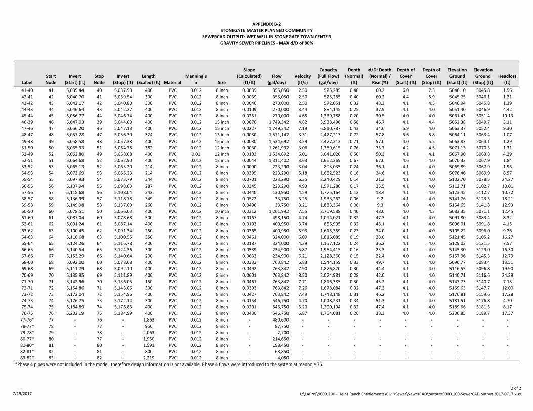
APPENDIX B-2
STONEGATE MASTER PLANNED COMMUNITY
SEWERCAD OUTPUT: WET WELL IN STONEGATE TOWN CENTER
GRAVITY SEWER PIPELINES - MAX d/D of 80%
Label
Start
Node
Invert
(Start) (ft)
Stop
Node
Invert
(Stop) (ft)
Length
(Scaled) (ft) Material
Manning's
n Size
Slope
(Calculated)
(ft/ft)
Flow
(gal/day)
Velocity
(ft/s)
Capacity
(Full Flow)
(gal/day)
Depth
(Normal)
(ft)
d/D: Depth
(Normal) /
Rise (%)
Depth of
Cover
(Start) (ft)
Depth of
Cover
(Stop) (ft)
Elevation
Ground
(Start) (ft)
Elevation
Ground
(Stop) (ft)
Headloss
(ft)
41-40 41 5,039.44 40 5,037.90 400 PVC 0.012 8 inch 0.0039 355,050 2.50 525,285 0.40 60.2 6.0 7.3 5046.10 5045.8 1.56
42-41 42 5,040.70 41 5,039.54 300 PVC 0.012 8 inch 0.0039 355,050 2.50 525,285 0.40 60.2 4.4 5.9 5045.75 5046.1 1.21
43-42 43 5,042.17 42 5,040.80 300 PVC 0.012 8 inch 0.0046 270,000 2.50 572,051 0.32 48.3 4.1 4.3 5046.94 5045.8 1.39
44-43 44 5,046.64 43 5,042.27 400 PVC 0.012 8 inch 0.0109 270,000 3.44 884,145 0.25 37.9 4.1 4.0 5051.40 5046.9 4.42
45-44 45 5,056.77 44 5,046.74 400 PVC 0.012 8 inch 0.0251 270,000 4.65 1,339,788 0.20 30.5 4.0 4.0 5061.43 5051.4 10.13
46-39 46 5,047.03 39 5,044.00 400 PVC 0.012 15 inch 0.0076 1,749,342 4.82 3,938,496 0.58 46.7 4.1 4.4 5052.38 5049.7 3.11
47-46 47 5,056.20 46 5,047.13 400 PVC 0.012 15 inch 0.0227 1,749,342 7.19 6,810,787 0.43 34.6 5.9 4.0 5063.37 5052.4 9.30
48-47 48 5,057.28 47 5,056.30 324 PVC 0.012 15 inch 0.0030 1,571,142 3.31 2,477,213 0.72 57.8 5.6 5.8 5064.11 5063.4 1.07
49-48 49 5,058.58 48 5,057.38 400 PVC 0.012 15 inch 0.0030 1,534,692 3.29 2,477,213 0.71 57.0 4.0 5.5 5063.83 5064.1 1.29
51-50 50 5,065.93 51 5,064.78 382 PVC 0.012 12 inch 0.0030 1,261,992 3.06 1,369,615 0.76 75.7 4.2 4.5 5071.13 5070.3 1.31
52-49 52 5,062.80 49 5,058.68 400 PVC 0.01 12 inch 0.0103 1,534,692 6.01 3,041,020 0.50 50.3 4.1 4.1 5067.90 5063.8 4.29
52-51 51 5,064.68 52 5,062.90 400 PVC 0.012 12 inch 0.0044 1,311,402 3.63 1,662,269 0.67 67.0 4.6 4.0 5070.32 5067.9 1.84
53-52 53 5,065.13 52 5,063.20 214 PVC 0.012 8 inch 0.0090 223,290 3.04 803,035 0.24 36.1 4.1 4.0 5069.89 5067.9 1.96
54-53 54 5,073.69 53 5,065.23 214 PVC 0.012 8 inch 0.0395 223,290 5.18 1,682,523 0.16 24.6 4.1 4.0 5078.46 5069.9 8.57
55-54 55 5,097.93 54 5,073.79 344 PVC 0.012 8 inch 0.0701 223,290 6.35 2,240,429 0.14 21.3 4.1 4.0 5102.70 5078.5 24.27
56-55 56 5,107.94 55 5,098.03 287 PVC 0.012 8 inch 0.0345 223,290 4.93 1,571,286 0.17 25.5 4.1 4.0 5112.71 5102.7 10.01
57-56 57 5,118.68 56 5,108.04 242 PVC 0.012 8 inch 0.0440 130,950 4.59 1,775,164 0.12 18.4 4.1 4.0 5123.45 5112.7 10.72
58-57 58 5,136.99 57 5,118.78 349 PVC 0.012 8 inch 0.0522 33,750 3.25 1,933,262 0.06 9.2 4.1 4.0 5141.76 5123.5 18.21
59-58 59 5,149.98 58 5,137.09 260 PVC 0.012 8 inch 0.0496 33,750 3.21 1,883,364 0.06 9.3 4.0 4.0 5154.65 5141.8 12.93
60-50 60 5,078.51 50 5,066.03 400 PVC 0.012 10 inch 0.0312 1,261,992 7.55 2,709,588 0.40 48.0 4.0 4.3 5083.35 5071.1 12.45
61-60 61 5,087.04 60 5,078.68 500 PVC 0.012 8 inch 0.0167 498,150 4.74 1,094,021 0.32 47.3 4.1 4.0 5091.80 5083.4 8.32
62-61 62 5,091.24 61 5,087.14 400 PVC 0.012 8 inch 0.0103 400,950 3.74 856,995 0.32 48.1 4.1 4.0 5096.01 5091.8 4.15
63-62 63 5,100.45 62 5,091.34 250 PVC 0.012 8 inch 0.0365 400,950 5.93 1,615,359 0.23 34.0 4.1 4.0 5105.22 5096.0 9.26
64-63 64 5,116.68 63 5,100.55 350 PVC 0.012 8 inch 0.0461 324,000 6.09 1,816,085 0.19 28.6 4.1 4.0 5121.45 5105.2 16.27
65-64 65 5,124.26 64 5,116.78 400 PVC 0.012 8 inch 0.0187 324,000 4.39 1,157,122 0.24 36.2 4.1 4.0 5129.03 5121.5 7.57
66-65 66 5,140.54 65 5,124.36 300 PVC 0.012 8 inch 0.0539 234,900 5.87 1,964,415 0.16 23.3 4.1 4.0 5145.30 5129.0 16.30
67-66 67 5,153.29 66 5,140.64 200 PVC 0.012 8 inch 0.0633 234,900 6.21 2,128,360 0.15 22.4 4.0 4.0 5157.96 5145.3 12.79
68-60 68 5,092.00 60 5,078.68 400 PVC 0.012 8 inch 0.0333 763,842 6.83 1,544,159 0.33 49.7 4.1 4.0 5096.77 5083.4 13.51
69-68 69 5,111.79 68 5,092.10 400 PVC 0.012 8 inch 0.0492 763,842 7.90 1,876,820 0.30 44.4 4.1 4.0 5116.55 5096.8 19.90
70-69 70 5,135.95 69 5,111.89 400 PVC 0.012 8 inch 0.0601 763,842 8.50 2,074,981 0.28 42.0 4.1 4.0 5140.71 5116.6 24.29
71-70 71 5,142.96 70 5,136.05 150 PVC 0.012 8 inch 0.0461 763,842 7.71 1,816,385 0.30 45.2 4.1 4.0 5147.73 5140.7 7.13
72-71 72 5,154.86 71 5,143.06 300 PVC 0.012 8 inch 0.0393 763,842 7.26 1,678,084 0.32 47.3 4.1 4.0 5159.63 5147.7 12.00
73-72 73 5,172.04 72 5,154.96 400 PVC 0.012 8 inch 0.0427 763,842 7.49 1,748,148 0.31 46.2 4.1 4.0 5176.81 5159.6 17.28
74-73 74 5,176.75 73 5,172.14 300 PVC 0.012 8 inch 0.0154 546,750 4.70 1,048,231 0.34 51.3 4.1 4.0 5181.51 5176.8 4.70
75-74 75 5,184.89 74 5,176.85 400 PVC 0.012 8 inch 0.0201 546,750 5.20 1,200,194 0.32 47.4 4.1 4.0 5189.66 5181.5 8.17
76-75 76 5,202.19 75 5,184.99 400 PVC 0.012 8 inch 0.0430 546,750 6.87 1,754,081 0.26 38.3 4.0 4.0 5206.85 5189.7 17.37
77-76* 77 - 76 - 1,863 PVC 0.012 8 inch - 480,600 - - - - - - - - -
78-77* 78 - 77 - 950 PVC 0.012 8 inch - 87,750 - - - - - - - - -
79-78* 79 - 78 - 2,063 PVC 0.012 8 inch - 2,700 - - - - - - - - -
80-77* 80 - 77 - 1,950 PVC 0.012 8 inch - 214,650 - - - - - - - - -
81-80* 81 - 80 - 1,591 PVC 0.012 8 inch - 198,450 - - - - - - - - -
82-81* 82 - 81 - 800 PVC 0.012 8 inch - 68,850 - - - - - - - - -
83-82* 83 - 82 - 2,219 PVC 0.012 8 inch - 4,050 - - - - - - - - -
*Phase 4 pipes were not included in the model, therefore design information is not available. Phase 4 flows were introduced to the system at manhole 76.
7/19/2017
2 of 2
L:\LAProj\9000.100 - Heinz Ranch Entitlements\Civil\Sewer\SewerCAD\output\9000.100-SewerCAD output 2017-0717.xlsx

APPENDIX B-3
STONEGATE MASTER PLANNED COMMUNITY
SEWERCAD OUTPUT: WET WELL IN STONEGATE TOWN CENTER
MANHOLES/WET WELL - MAX d/D of 80%
Label
Elevation
(Ground) (ft)
Elevation
(Rim) (ft)
Elevation
(Invert) (ft)
Depth
(Structure) (ft)
Diameter
(in)
Peak Load
Applied at
Junction (gpd)
Total Peak
Flow (gpd)
WETWELL 5,040.13 5,040.13 5,028.59 11.54 - 0 4,204,947
0 5,040.64 5,040.64 5,029.39 11.25 48 754,605 4,204,947
1 5,044.40 5,044.40 5,033.62 10.78 48 0 3,450,342
2 5,049.55 5,049.55 5,044.07 5.48 48 0 1,147,500
3 5,050.23 5,050.23 5,045.39 4.83 48 0 495,720
4 5,051.98 5,051.98 5,047.21 4.77 48 162,000 495,720
5 5,056.16 5,056.16 5,051.40 4.77 48 0 333,720
6 5,064.12 5,064.12 5,059.35 4.77 48 0 333,720
7 5,068.92 5,068.92 5,064.15 4.77 48 97,200 333,720
8 5,078.09 5,078.09 5,073.32 4.77 48 101,250 236,520
9 5,085.68 5,085.68 5,080.92 4.77 48 0 135,270
10 5,096.37 5,096.37 5,091.60 4.77 48 0 135,270
11 5,112.67 5,112.67 5,107.90 4.77 48 38,070 135,270
12 5,122.15 5,122.15 5,117.48 4.67 48 97,200 97,200
13 5,054.41 5,054.41 5,049.47 4.93 48 0 651,780
14 5,069.65 5,069.65 5,055.93 13.72 48 0 651,780
15 5,061.55 5,061.55 5,056.72 4.83 48 33,750 651,780
16 5,066.20 5,066.20 5,060.66 5.54 48 0 618,030
17 5,067.15 5,067.15 5,062.38 4.77 48 0 326,430
18 5,074.26 5,074.26 5,069.50 4.77 48 0 326,430
19 5,079.43 5,079.43 5,074.67 4.77 48 129,600 326,430
20 5,082.26 5,082.26 5,077.49 4.77 48 0 196,830
21 5,093.20 5,093.20 5,088.43 4.77 48 0 196,830
22 5,107.25 5,107.25 5,102.49 4.77 48 44,550 196,830
23 5,112.90 5,112.90 5,108.14 4.77 48 30,780 152,280
24 5,126.20 5,126.20 5,121.54 4.67 48 121,500 121,500
25 5,072.22 5,072.22 5,067.45 4.77 48 56,700 291,600
26 5,075.71 5,075.71 5,070.94 4.77 48 0 234,900
27 5,093.70 5,093.70 5,077.41 16.30 48 0 234,900
28 5,086.15 5,086.15 5,079.52 6.63 36 52,650 234,900
29 5,086.83 5,086.83 5,082.06 4.77 36 0 182,250
30 5,089.54 5,089.54 5,084.77 4.77 36 56,700 182,250
31 5,094.80 5,094.80 5,090.03 4.77 36 0 125,550
32 5,109.88 5,109.88 5,105.11 4.77 36 0 125,550
33 5,117.02 5,117.02 5,112.25 4.77 36 36,450 125,550
34 5,132.11 5,132.11 5,127.44 4.67 36 89,100 89,100
35 5,049.57 5,049.57 5,043.32 6.26 48 0 1,147,500
36 5,049.61 5,049.61 5,042.02 7.60 48 0 1,147,500
37 5,049.65 5,049.65 5,040.72 8.94 48 113,400 1,260,900
38 5,049.67 5,049.67 5,039.42 10.25 48 0 1,260,900
39 5,049.65 5,049.65 5,035.32 14.33 48 0 3,450,342
40 5,045.84 5,045.84 5,037.80 8.04 48 85,050 440,100
41 5,046.10 5,046.10 5,039.44 6.66 48 0 355,050
42 5,045.75 5,045.75 5,040.70 5.05 48 85,050 355,050
43 5,046.94 5,046.94 5,042.17 4.77 48 0 270,000
44 5,051.40 5,051.40 5,046.64 4.77 48 0 270,000
45 5,061.43 5,061.43 5,056.77 4.67 48 270,000 270,000
7/19/2017
1 of 2
L:\LAProj\9000.100 - Heinz Ranch Entitlements\Civil\Sewer\SewerCAD\output\9000.100-SewerCAD output 2017-0717.xlsx

APPENDIX B-3
STONEGATE MASTER PLANNED COMMUNITY
SEWERCAD OUTPUT: WET WELL IN STONEGATE TOWN CENTER
MANHOLES/WET WELL - MAX d/D of 80%
Label
Elevation
(Ground) (ft)
Elevation
(Rim) (ft)
Elevation
(Invert) (ft)
Depth
(Structure) (ft)
Diameter
(in)
Peak Load
Applied at
Junction (gpd)
Total Peak
Flow (gpd)
46 5,052.38 5,052.38 5,047.03 5.35 48 0 1,749,342
47 5,063.37 5,063.37 5,056.20 7.16 48 178,200 1,749,342
48 5,064.11 5,064.11 5,057.28 6.83 48 36,450 1,571,142
49 5,063.83 5,063.83 5,058.58 5.25 48 0 1,534,692
50 5,071.13 5,071.13 5,065.93 5.20 48 0 1,261,992
51 5,070.32 5,070.32 5,064.68 5.64 48 49,410 1,311,402
52 5,067.90 5,067.90 5,062.80 5.10 48 0 1,534,692
53 5,069.89 5,069.89 5,065.13 4.77 36 0 223,290
54 5,078.46 5,078.46 5,073.69 4.77 48 0 223,290
55 5,102.70 5,102.70 5,097.93 4.77 48 0 223,290
56 5,112.71 5,112.71 5,107.94 4.77 48 92,340 223,290
57 5,123.45 5,123.45 5,118.68 4.77 48 97,200 130,950
58 5,141.76 5,141.76 5,136.99 4.77 48 0 33,750
59 5,154.65 5,154.65 5,149.98 4.67 48 33,750 33,750
60 5,083.35 5,083.35 5,078.38 4.97 48 0 1,261,992
61 5,091.80 5,091.80 5,087.04 4.77 48 97,200 498,150
62 5,096.01 5,096.01 5,091.24 4.77 48 0 400,950
63 5,105.22 5,105.22 5,100.45 4.77 48 76,950 400,950
64 5,121.45 5,121.45 5,116.68 4.77 48 0 324,000
65 5,129.03 5,129.03 5,124.26 4.77 48 89,100 324,000
66 5,145.30 5,145.30 5,140.54 4.77 48 0 234,900
67 5,157.96 5,157.96 5,153.29 4.67 48 234,900 234,900
68 5,096.77 5,096.77 5,092.00 4.77 48 0 763,842
69 5,116.55 5,116.55 5,111.79 4.77 48 0 763,842
70 5,140.71 5,140.71 5,135.95 4.77 48 0 763,842
71 5,147.73 5,147.73 5,142.96 4.77 48 0 763,842
72 5,159.63 5,159.63 5,154.86 4.77 48 0 763,842
73 5,176.81 5,176.81 5,172.04 4.77 48 217,092 763,842
74 5,181.51 5,181.51 5,176.75 4.77 48 0 546,750
75 5,189.66 5,189.66 5,184.89 4.77 48 0 546,750
76 5,206.85 5,206.85 5,202.19 4.67 48 546,750 546,750
77* - - - - 48 178,200 480,600
78* - - - - 48 85,050 87,750
79* - - - - 48 8,100 2,700
80* - - - - 48 16,200 214,650
81* - - - - 48 129,600 198,450
82* - - - - 48 56,700 68,850
83* - - - - 48 12,150 4,050
*Phase 4 pipes were not included in the model, therefore design information is not available. Phase 4 flows were introduced
to the system at manhole 76.
7/19/2017
2 of 2
L:\LAProj\9000.100 - Heinz Ranch Entitlements\Civil\Sewer\SewerCAD\output\9000.100-SewerCAD output 2017-0717.xlsx

Appendix C
Preliminary Wet Well Sizing Calculations

Buildout Inflow to Wet Well Wet Well Size
Qin, mgd (StoneGate MPC) 2.30 Dimensions (square), ft 10
Qin, mgd (StoneGate TC w/10% increase) 0.55 Area, A, sq ft 100.0
Total Qin, mgd 2.85
Qin, gpm 1,990
Influent Pipeline to LS from StoneGate
Discharge from Wet Well Invert of JN S. of Hwy 5035.7
Qout, mgd 2.85 Distance JN S. of Hwy to JN N. of Hwy 400
Qout, gpm 1,990 Distance JN N. of Hwy to Lift Station 2,780
Spacing between MHs, ft 400
Minimum Cycle Time between Pump Starts (aka Cycle Time) No. MHs from JN N. of Hwy to LS 7
Tmin, minutes 8 Diff in Inverts at MHs 0.1
Equivalent Starts per Hour 7.5 Min Pipe Slope 0.0020
Flygt pumps: Up to 15 starts per hour Invert of JN S. of Hwy 5034.8
KSB rep: 15-30 starts per hour for pumps over 30 hp
Min Storage Volume Required, Pumps Off
Vmin = Tmin*Qout/4, gallons 3,980
Wet Well Depth
Minimum Storage Depth Finish Grade Elevation @ LS, ft 5040.0
Hmin, ft = Vmin/A = 5.32 Lowest Inlet Pipe Invert, ft 5028.5
Reserve Depth, ft 1.0
Min Pump Submergence Pumps On (HWL), ft 5028
Recommended S, ft 3.0 Minimum Storage Depth, ft 5.3
Flygt pumps range from 17-20" Pumps Off (LWL), ft 5022.2
KSB pumps minimum 27.6" for automatic operation Sump Depth, ft 3.0
Base of Wet Well, ft 5019.2
Reserve
Reserve Depth, ft 1.00
Equivalent Volume, gallons 748 Total Depth Wet Well, ft 20.8
Equivalent Storage Time, min 0.38 Static Head to CSWRF, ft 63.6
Wet Well Fill Time (10 State Standards < 30 min)
Phase 1 ADF, gpm 173 Buildout, ADF, gpm 991
Time to Fill Wet Well, min 27.4 Time to Fill Wet Well, min 4.8
Phase 1 PHF, gpm 346 Buildout, PHF, gpm 1,982
Time to Fill Wet Well, min 13.7 Time to Fill Wet Well, min 2.4
STONEGATE MASTER PLANNED COMMUNITY
PRELIMINARY WET WELL SIZING CALCULATIONS
7/19/2017 L:\LAProj\9000.400 - Stonegate Offsite Engineering\Civil\Sewer\Calculations\Lift Station Design\Lift Station.xlsx

Appendix D
Preliminary Pump and Force Main Sizing Calculations

Proposed Lift Station Dual Force Main
Wet Well Low EL, ft 5,022.2 No. of Force Mains 3
Wet Well High EL, ft 5,027.5 Pipe Length, ft 19,400
Pipe Diameter, inches 10
Discharge: CSWRF Pipe Area, ft2
0.55
Ground EL @ MH, ft 5,085.8 Roughness Coefficient, C 140
StoneGate MPC + TC Buildout Sewer Generation
Peak Flow, mgd 2.85 Total Dynamic Head (TDH) = hs + hf + hm + V2/2g + hp
Peak Flow, gpm 1,990 hs = Static Head
(includes 10% adder to StoneGate TC flows) hf = Friction Losses
hm = Minor Losses
Max Static Head, ft 63.6 V2/2g = Velocity Head
Min Static Head, ft 58.3 hp = Pressure Head
Equally Sized Force Mains
No. of
FMs
Design Flow,
Each Pipe
(gpm)
Design Flow,
Each Pipe
(cfs)
Velocity,
Each Pipe
(fps)Static Head,
hs (ft)
Friction
Loss,
hf (ft)
Velocity
Head,
V2/2g (ft)
TDH
(ft)
3 663 1.48 2.71 63.6 48.7 0.1 112.5
Estimated Pump Sizing
No. Duty Pumps 2
Q per pump, gpm 995
Q per pump, cfs 2.22
TDH, ft 113.0
Pump horsepower, HP 28.4
Min Pump Efficiency w/in Operating Range 58.0% Brake Horsepower, HP 49.0
Estimated Motor Efficiency 94.5% Total Horsepower, HP 51.9
Required Motor Size, HP
(each pump)60
STONEGATE MASTER PLANNED COMMUNITY
PUMP CALCULATIONS - BUILDOUT LIFT STATION
Equally Sized
Force Mains
7/19/2017 L:\LAProj\9000.400 - Stonegate Offsite Engineering\Civil\Sewer\Calculations\FM Sizing\FM and Pump Sizing.xlsx

STONEGATE MASTER PLANNED COMMUNITY
PUMP CURVES VERSUS SYSTEM CURVES
40
50
60
70
80
90
100
110
120
130
140
150
160
170
180
190
200
- 200 400 600 800 1,000 1,200 1,400 1,600 1,800 2,000 2,200 2,400 2,600 2,800 3,000 3,200 3,400
TD
H, F
T
Q, GPM
3 PUMP SYSTEM: 2 DUTY + 1 STANDBY
Sulzer XFP 150M-CB2 Sulzer XFP 150M-CB2
FM: (1) 10, DR 18 (235), 9.79" ID FM: (1) 10, DR 25 (165), 10.16" ID
FM: (2) 10s, DR 18 (235), 9.79" ID FM: (2) 10s, DR 25 (165), 10.16" ID
FM: (3) 10s, DR 18 (235), 9.79" ID FM: (3) 10s, DR 25 (165), 10.16" ID
Flow Stages Peak Buildout Flow
10"
10"+10"10"+10"+10"
1
25
4
3
0%10%20%30%40%50%60%70%80%
0%10%20%30%40%50%60%70%80%
- 200 400 600 800 1,000 1,200 1,400 1,600 1,800 2,000 2,200 2,400 2,600 2,800 3,000 3,200 3,400
Pu
mp
Eff
icie
ncy
7/19/2017 L:\LAProj\9000.400 - Stonegate Offsite Engineering\Civil\Sewer\Calculations\FM Sizing\FM and Pump Sizing.xlsx