computer structure - uc3mocw.uc3m.es/.../computer-structure/unit6.pdfhow many bytes does a disk...
TRANSCRIPT

Computer Structure
Unit 6. Input/Output Systems
Departamento de InformáticaGrupo de Arquitectura de Computadores, Comunicaciones y Sistemas
UNIVERSIDAD CARLOS III DE MADRID
Unit 6. Input/Output Systems

Contents
� Peripheral concept� Structure of a disk drive� Buses� I/O modules� I/O techniques
Computer Structure
� I/O techniques� Programmed I/O� Interrupts� DMA
ARCOS 2

Peripheral concept
� Peripheral:
� Device attached to a CPU connected by using input/output modules
Peripheral
Computer Structure
input/output modules
� Used to store information or for the communication with the computer
ARCOS 3

Classification of peripherals
� Communication: �Human-computer
� (Terminal) keyboard, mouse, …� (Printer) plotter, scanner, …
�Computer-computer� Modem, network adapter
Computer Structure
� Modem, network adapter�Physical environment
� (read/action) x (analogical/digital)
� Storing: � Direct access (disks, DVD, …)� Sequential access (tapes)
ARCOS 4

Peripheral and I/O units
� Peripheral�Device attached to the
computer
� I/O module or I/O unit
Peripheral
I/O module
Computer Structure
� I/O module or I/O unit�Also called controller�Interface between the
processor and the devices, that hides the devices characteristics
I/O module
ARCOS 5

Example: Disk drive
Device
I/O module
peripheral
Computer Structure
I/O module
ARCOS 6

History
� First disk drive was built in 1956� Installed on a IBM RAMAC 305� 50 disks of 24”� 5 MB of data� Hire per year: 35000 $
Computer Structure
� Hire per year: 35000 $
� In 1980 appeared the first 5 ¼” disk� 5 MB� 10000 %
� In 1997 appeared the first disk with 15000 RPM
ARCOS 7

Disk anatomy
Engine
Computer Structure
www.snia.org
ARCOS 8

Disk anatomy
Disks (plates)
Computer Structure
www.snia.org
ARCOS 9

Disk anatomy
Read/write heads
Computer Structure
www.snia.org
ARCOS 10

Disk anatomy
control and mechanic
Computer Structure
www.snia.org
ARCOS 11

Disk anatomy
� Disk controller� Scheduling commands� Error correction� Optimization� Check integrity
Computer Structure
� Check integrity� RPM control� Disk cache
www.snia.org
ARCOS 12

Multiple plates
Computer Structure
rotation
ARCOS 13

Cylinders
�Data accessed by all disk heads
Computer StructureARCOS 14

Tracks and sectors
� Tracks� Concentric rings
� Sector� Division of the disk
surface made when the
Computer Structure
surface made when the disk is formatted (512 bytes)
� Blocks� File System writes in
blocks� Sector groups
ARCOS 15

Distribution of sectors
Computer StructureARCOS 16

Evolution of disk sizes
Computer Structure
Memory SystemsCache, DRAM, DiskBruce Jacob, Spencer Ng, David WangElsevier
ARCOS 17

Capacity
� Bits per inch� Depend on read/write head, physical medium, disk rotation
and bus velocity� Tracks per inch
� Depend on read/write head, physical medium, head
Computer Structure
� Depend on read/write head, physical medium, head precision, disk precision
ARCOS 18

Storage capacity
� For constant angular velocity disks:� ns: number of surfaces� p: trakcs per surface� s: sectos per track� ts: bytes per sector
ss tspnCapacity ×××=
Computer Structure
� For multple zone recording:� z: number of zones� pi: number of tracks per zone I� si: sectors per track in zone i
)(1
i
z
iiss sptnCapacity ×××= ∑
=
ARCOS 19

Recording techniques
� Over the last decade the magnetic recording has achieved 100% growth of Areal Density (AD)
� Each bit cell in a track is composed of multiple magnetic grains� The size or the number of magnetic grains in a bit cell cannot be scaled
much below a diameter of ten nanometers due to:� Superparamagneticeffect� Superparamagneticeffect� Ambient temperature would become magnetic grains unstable
� Recording techniques:� Longitudinal recording: store data in a longitudinal way over a
horizontal plane� Perpendicular recording: data are stored in vertical way, increasing the
disk capacity
Computer StructureARCOS 20

Read/write head
Computer Structure
Memory SystemsCache, DRAM, DiskBruce Jacob, Spencer Ng, David WangElsevier
ARCOS 21

Areal density
� Number of bits that can be recorded per square inch (AD):
� Until 1998 the annual increase rate was 29%
( ) trackaonInch
Bitssurfacediskaon
Inch
TracksADdensityAreal ×=
� Until 1998 the annual increase rate was 29%� 1998-1997 the annual increase rate was 60%� 1997-2003 the annual increase rate was 100%� 2003-2011 the annual increase rate was 30%� In 2011 the bigger areal density in commercial products was 400
billions of bits per inc� The cost per bit has improved in a factor of 1.000.000 between 1983
and 2011
Computer StructureARCOS 22

Evolution of areal density
Computer Structure
Memory SystemsCache, DRAM, DiskBruce Jacob, Spencer Ng, David WangElsevier
ARCOS 23

Disks and main memory
� The latency of a DRAM memory is 100.000 less than the latency of a disk
� The cost per GB in a DRAM memory is 30-150 times the cost per GB of a disk
� In 2011:� In 2011:� A disk transfers 200 MB/s in a disk of 600 GB and costs
400 $� A 4GB DRAM memory transfers 16.000 MB/s and costs
200$
Computer StructureARCOS 24

Disks and main memory
Computer Structure
Patterson y Hennesy
ARCOS 25

Addressing
� Types of addressing:� Physical addressing: cylinder-track-sector. � Logical blocks addressing (LBN)
� Each sector has a logical number and the mapping is done by the disk
Computer Structure
done by the disk� Current disk controllers do the mapping between LBN
and physical addresses
ARCOS 26

Access time
� Seek time (Tseek): time to move the head from the current cylinder to the target cylinder
� Rotational latency(Trotate): delay waiting for the rotation of the disk to bring the required disk sector under the read-write head� Average rotational latency is calculated as half time it takes
Computer Structure
� Average rotational latency is calculated as half time it takes the disk to do one revolution
� Data transfer time (Ttransfer): amount of data divided by the data transfer rate
� Access time� Taccess= Tseek+ Trotate+ Ttransfer
ARCOS 27

Seek and rotation
Computer Structure
Memory SystemsCache, DRAM, DiskBruce Jacob, Spencer Ng, David WangElsevier
ARCOS 28

Seek time
� Elements to include:� Head acceleration time (Tacc)� Coast period (Tc) for long distances� Deceleration time(Tdec)� Head Settling time (Ts). � Head Settling time (Ts). � The average seek time is generally taken to be the average
time needed to seek between two random tracks on the disk, called Daverage
Computer Structure
22
2
1decdecaccaccaverage tataD ×+××=
ARCOS 29

Seek time
� Seek time for near tracks
Computer Structure
� Seek time for long tracks
Memory SystemsCache, DRAM, DiskBruce Jacob, Spencer Ng, David WangElsevier
ARCOS 30

Seek time
Dtt average==
� When the acceleration time is equal to the deceleration time:
Computer Structure
a
Dtt average
decacc ==
saverage
seek ta
Dt +×= 2
ARCOS 31

Seek time
� When the areal density increase the capacity of cylinders increase too:� The probability of reducing the number of seeks is
increased� Increase the probability that the next data to request are in � Increase the probability that the next data to request are in
the same cylinder, reducing in this way the number of seeks
Computer StructureARCOS 32

Rotational latency
� Rotational latency is generally calculated as half the time it takes the disk to do one revolution
RPMTrotate
31060
2
1 ××=
Computer Structure
� Zero-latency access� New feature of modern disk drives, can start transferring
data when the disk head is positioned above any of the sectors in a request
� If multiple contiguous sectors are required to be read, the disk head can read the sectors from the media into its buffer in any order
ARCOS 33

Rotational speed and rotational latency
Rotational Speed Rotational Latency (in ms)
5400 5.6
7200 4.2
Computer Structure
7200 4.2
10000 3.0
12000 2.5
15000 2.0
ARCOS 34

Evolution of RPM
Computer Structure
Memory SystemsCache, DRAM, DiskBruce Jacob, Spencer Ng, David WangElsevier
ARCOS 35

Evolution of rotational latency
Computer Structure
Memory SystemsCache, DRAM, DiskBruce Jacob, Spencer Ng, David WangElsevier
ARCOS 36

Data Transfer time
� Two elements:� External data rate to measure the transfer rate between
memory and disk cache� Transfer rate between disk cache and disk storage media
� Data transfer time can be calculated as:N request 60×=
� Where Ntrack denotes the number of sectors on a track, and Nrequest the data length of a request measured in sectors.
� The ratio of the sectors of the outmost zone to that of the innermost zone ranges from 1.43 to 1.58.
Computer Structure
RPMN
NT
track
requesttransfer
60×=
ARCOS 37
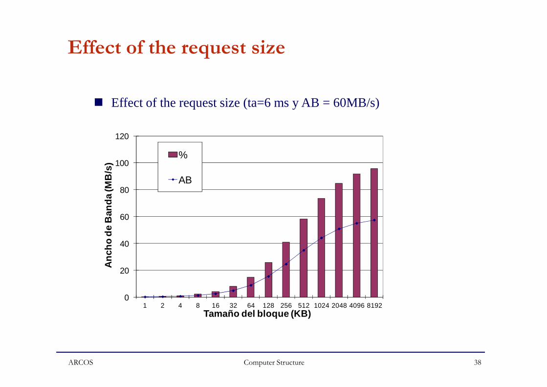
Effect of the request size
80
100
120
Anc
ho d
e B
anda
(MB
/s)
%
AB
� Effect of the request size (ta=6 ms y AB = 60MB/s)
Computer Structure
0
20
40
60
80
1 2 4 8 16 32 64 128 256 512 1024 2048 4096 8192
Anc
ho d
e B
anda
(MB
/s)
Tamaño del bloque (KB)
ARCOS 38

Disk controller
� Circuits and components to control the disk:� Storage interface� Disk sequencer� Error correction code(ECC)� Servo motor� Servo motor� Microprocessor� Buffer controller� Disk cache
Computer StructureARCOS 39

Storage interface
� Offers a standard protocol for the disk drives to communicate with its client.� IDE, SCSI, FC, SATA
� Exposes storage capacity as a linear array of fixed-size blocks to file systemsto file systems
� Data access is specified by a LBN and a data block length� The disk controller is responsible for translating the LBN to
physical addresses (Cylinder/Head/Sector)� There are other types of devices: Object-based Storage
Devices (OSD)
Computer StructureARCOS 40

Disk access
Computer StructureARCOS 41

Disk cache
� Exploit the locality� Reduce physical access to disk
� Reduce the heat dissipation� Increase the performance
� Disk cache have almost no temporal locality because the host � Disk cache have almost no temporal locality because the host memory (OS) is larger than the disk cache
� Implements perfectingg
Computer StructureARCOS 42

Disk cache
� Replacement algorithms� Random Replacement� Least Frequently Used (LFU)� Least Reccently Used (LRU)
� Systems designers generally believe that the size of a cache should be at least 0.1 to 0.3 % of the backing store.
Computer StructureARCOS 43

Disk scheduler
� Disk drives maintain a queue with pending requests� Disk schedulers are designed to minimize the access time by
reordering or rearranging pending request in the queue to reduce the seek time and rotational latency
� Scheduling algorithms:� First Come First Served (FCFS)� Shortest Seek Time First (SSTF)� SCAN� C-SCAN� LOOK
Computer StructureARCOS 44

Other elements
� Disk sequencer: Manages the data transfer between storage interface and data buffer
� ECC: responsible for appending ECC symbols to the user data and also checking and correcting errors
� Servo control: detects the current position of the disk head and � Servo control: detects the current position of the disk head and controls track following and seeking
� Microprocessor: controls the disk behavior� Buffer controller: provides arbitration and raw signal control
to the bank of buffer memory
Computer StructureARCOS 45

Exercise
� How many bytes does a disk drive of 250 GB store?
Computer StructureARCOS 46

Remainder
Name Abr Factor IS
Kilo K 210 = 1,024 103 = 1,000
Mega M 220 = 1,048,576 106 = 1,000,000
Giga G 230 = 1,073,741,824 109 = 1,000,000,000
Tera T 240 = 1,099,511,627,776 1012 = 1,000,000,000,000
Peta P 250 = 1,125,899,906,842,624 1015 = 1,000,000,000,000,000
Exa E 260 = 1,152,921,504,606,846,976 1018 = 1,000,000,000,000,000,000
Computer Structure
� 1 KB = 1024 bytes, but in IS is 1000 bytes� Manufactures of disk drives and telecomunications use IS:
� A disk drive of 30 GB stores 30 x 109 bytes� A network of 1 Mbit/s transfers 106 bps.
Exa E 2 = 1,152,921,504,606,846,976 10 = 1,000,000,000,000,000,000
Zetta Z 270 = 1,180,591,620,717,411,303,424 1021 = 1,000,000,000,000,000,000,000
Yotta Y 280 = 1,208,925,819,614,629,174,706,176
1024 = 1,000,000,000,000,000,000,000,000
ARCOS 47

Exercise
� Consider a disk with:� Rotational speed: 7200 rpm� Disk platters: 5, with 2 surfaces per plate� Number of tracks per plate: 30000� Sectors per plate: 600� Seek time: 1 ms per each 100 tracks
Computer Structure
� Seek time: 1 ms per each 100 tracks� If the disk head is in track 0 and the data requested are stored
in track 600. Compute:� Capacity of the disk� Rotational latency� Transfer time needed to transfer a sector� Access time for a sector
ARCOS 48

Exercise
� A disk drive has a rotational speed of 7200 rpm and a constant areal density of 604 sectors per track. The average access time in 4ms� Compute the access time to a sector
Computer StructureARCOS 49

Exercise
� A disk drive has an average accesss time of 4 ms, 15000 rpm and 500 sectors per track. Let be a file of 2500 sectors with a size of 1.22 MB. Compute the time needed to read the file in the following scenarios:� The file is stored in sequential way, and occupies 5
Computer Structure
� The file is stored in sequential way, and occupies 5 consecutive tracks.
� The sectors of the file are randomly stored in the disk
ARCOS 50

Reliability
� MTTF: mean time to failure� MTTR: mean time to restore� Reliability is defined as:
MTTFyreliabilit
+=
Computer Structure
� What does a reliability of 99% mean?� In 365 consecutive days the device works correctly
99*365/100 = 361.3 days� Failures in disk drives produce the 20-55% of the failures in
the storage systems.
MTTRMTTFyreliabilit
+=
ARCOS 51
Energy consumption
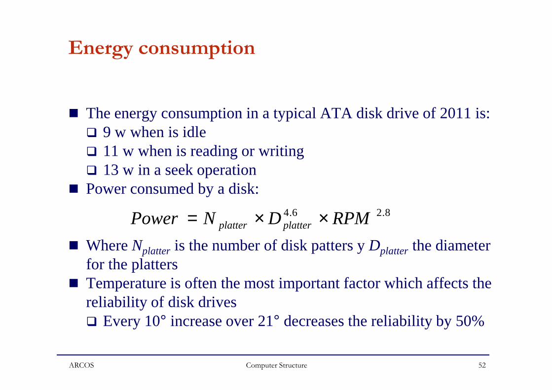
� The energy consumption in a typical ATA disk drive of 2011 is:� 9 w when is idle� 11 w when is reading or writing� 13 w in a seek operation
� Power consumed by a disk:� Power consumed by a disk:
� Where Nplatter is the number of disk patters y Dplatter the diameter for the platters
� Temperature is often the most important factor which affects the reliability of disk drives� Every 10° increase over 21° decreases the reliability by 50%
Computer Structure
8.26.4 RPMDNPower platterplatter ××=
ARCOS 52

Power state transition of disk drives
R/W requests
(1) (3)
Computer Structure
Active Idle Standby(2)
(4)
ARCOS 53

Power state transitions
� (1): there is no succeeding request, the disk drive is transferred to the idle state where the disk platters are still spinning but the electronics may be partially unpowered
� (2): Disk drive receives a request � (3): To conserve energy, the disk drive can be spun down to � (3): To conserve energy, the disk drive can be spun down to
the standby state where the disk stops spinning and the head is moved off the disk
� (4): To perform requests after entering the standby state, the disk drive must be transferred back from the standby state to the active state by spinningg up
Computer StructureARCOS 54

Energy conservation methods
� Based on timeout strategies. Once a disk drive is idle for a specific period of time, the disk drive is spun down to save energy
� Dynamic prediction. Based on the behaviors of application� Stochastic mechanisms. � Stochastic mechanisms. � Application-aware power management
� Applications inform over the access pattern (in the source code or with complier-driven methods)
Computer StructureARCOS 55

Impacts of power state transitions
� The power state transition can incur a significant energy cost and time penalty as the disk patters have to spun up to full speed.
� Reduce the reliability. Disk drives manufacturers provide a duty-cycle rating which is the number of times the disk platters duty-cycle rating which is the number of times the disk platters can be spun down before the chances of failures increase to more than 40% on drive spin up.
� The methods cannot be applied toe server disk drives, since the spinning down and spinning up time of the server disk drives are much longer than that of the desktop and laptop
Computer StructureARCOS 56

RAID disk
� Redundant Array of Inexpensive Disks� Set of disk drives that works as an unit� Distributed data across several disks� Store redundant information
Computer StructureARCOS 57

Parallelism in disks
� Disk stripping� Data are divided in blocks and each block is written in a
different disk� RAID 0� Increase the performance
� Distributes the I/O load through several disks and channels
0 1 2
3 4 5
Computer StructureARCOS 58

Advantages of parallelism in disks
� Large requests� Parallelism inside the request� The request can be satisfied by several disks� Reduce the access time
� Short requests� Parallelism among requests� Parallelism among requests� Several requests can be made at the same time� Seeks in parallel� Transfers in parallel
Computer StructureARCOS 59

Problem: Reliability
0,5
0,6
0,7
0,8
0,9
1
Fia
bilid
ad
�Serial system
0
0,1
0,2
0,3
0,4
1 2 4 8 16 32 64
Número de discos
Fia
bilid
ad�Reliaibity
∏= iRR
�Any failure is supoorted
Computer StructureARCOS 60

RAID 1
0 1 23 4 5
0 1 23 4 5
� 2 replicated RAID0� One read operation and two write operations
� A write operation on each block� A read operation using one block
� Redundancy: 100%� Parallelism limited� Easy recovery
Computer StructureARCOS 61

RAID 3
A0 A1 A2
B0 B1 B2
A ParityB Parity
Compute parity
� A data block is divided in bytes and theses bytes are written in all disks
� Parity computed in write operations� Reduce the transfer time for reads and writes
� Appropriate for large requests
Computer StructureARCOS 62

RAID 4
A0 A1 A2
B0 B1 B2
A ParityB Parity
Paritygeneration
� Each block is stored in a different disk� Transfer time for reads similar to use only one disk� No parallelism in write operations
� All write operations use the parity disk� Concurrent read operations
Computer StructureARCOS 63

Parity generation
D0 D1 D2 D3 P0-3
xor
Whole stripe efficient
D0 D1 D2 D3 P0-3
D'3
xor
Short write operations performance problems
Computer StructureARCOS 64

Data rebuilding
xor
D0
D3
Computer Structure
D2
P0-3D0 D1
ARCOS 65

RAID 5
A0 A1 A2B0 B1 B Parity
A ParityB 2
Paritygeneration
� Parity blocks are distributed among all disk drives� Reducing the contention over the parity disk� Concurrent reads and writes operations
� Appropriate for high I/O throughput
Computer Structure
B0 B1 B Parity B 2
C0 C1 C2C Parity
ARCOS 66

Reliability calculation
� If P is the probability of failure, the reliability R is:
R = 1-P
� Reliability of a serial system� Reliability of a serial system� Reliability of a parallel system� Reliability of a k-out-of-n system
Computer StructureARCOS 67

Reliability of a serial system
∏= iRR
Computer StructureARCOS 68

Reliability of a parallel system
∏ −−= )1(1 iRR
Computer StructureARCOS 69

Reliability of a k-out-of-n system
K-out-of-n
rnrnr
kr
RRr
nnkR −
=
=
−
=∑ )1(),(
Computer StructureARCOS 70

Reliability of a RAID1
0 1 23 4 5
0 1 23 4 5
D0
D0 D1 D2 D0’ D1’ D2’
D1 Dn
D0’ D1’ Dn’
∏=
=
−=−−−=2
1
22)2())1)(1(1(
ni
i
n
RRRRR
Computer StructureARCOS 71

Reliability of a RAID5
A0 A1 A2B0 B1 B Parity
A ParityB 2
C0 C1 C2C Parity
Computer Structure
� For n disks is a (n-1)-out-of-n model
)1()1(),1( 1
1
nRnRRRr
nnnR nnrnr
nr
nr
−+=−
=− −−
=
−=∑
ARCOS 72

Reliability
0,6
0,8
1
1,2
Rel
iabi
lity
0
0,2
0,4
0,6
1 4 8 16 32 64 128
Rel
iabi
lity
Number of disks
RAID 0
RAID 1
RAID 5
RAID 5+0
Computer StructureARCOS 73

Reliability/redundancy
0,8
1
1,2
reliability
redundancy
0
0,2
0,4
0,6
RAID 0 RAID 1 RAID 5 RAID 5+016 disks
Computer StructureARCOS 74

Solid state disks
� Storage devices that use semiconductors to data storage� Based on flash memories
� Non volatile memories� Based on DDR memories
� Require batteries and disk backup to provide non volatile
Computer StructureARCOS 75

Flash memory
� Non volatile semiconductor memory� types:
� NOR flash� Based on NOR gates� Byte accessible� Faster than NAND flash
� NAND flash� Based on NAND gates� Less expensive and much more popular than NOR flash� Accessed using blocks
Computer StructureARCOS 76

Write operation in Flash
� A NAND flash is composed of a fixed number of blocks, where each block consists of a number of pages, and each page has a fixed-size main data area
� Data on a NAND flash memory is read or written in a unit of one page, and the erasing is performed in a unit of one blockone page, and the erasing is performed in a unit of one block
� A block is erased put “1” in all bits� The write operation only can write “0”
Computer StructureARCOS 77

Access time
Computer StructureARCOS 78

I/O operations
Computer StructureARCOS 79

Prices
Computer StructureARCOS 80

Performance
Computer StructureARCOS 81

Performance
� Mixtures loads
Computer StructureARCOS 82

Performance
Computer StructureARCOS 83

Performance
Computer StructureARCOS 84

Bus
� A bus allows the communication among two or more devices
� Uses several lines to transmit bitsE1 E2 E3
Computer Structure
transmit bits� The bus is shared� Types:
� Serial� Parallel
ARCOS 85

System bus
� System bus
� Connects the main components in the computer
� Is the union of three buses:� Control
CPU Memory I/O
Computer Structure
� Control � Address� Data
ARCOS 86

Buses
� Data bus� Address bus
� Memory and I/O addresses� Bus de control
� Control signals and temporization
CPU Memory I/O
Computer Structure
temporization
ARCOS 87

Disk controllers
Computer Structure
Memory SystemsCache, DRAM, DiskBruce Jacob, Spencer Ng, David WangElsevier
ARCOS 88

Bus hierarchy
Procesador
Memoria principal
CacheBus local
Controlador local de E/S
Computer Structure
principal
SCSI Modem
SerieInterfaz con el bus de
expansión
Red
Bus de expansión
Bus del sistema
ARCOS 89

Example of configuration
Computer Structure
Memory SystemsCache, DRAM, DiskBruce Jacob, Spencer Ng, David WangElsevier
ARCOS 90

I/O module
� I/O modules perform the connection among the peripheral devices and the processor or the memory
Memory
Computer Structure
Device
I/Omodule
Memory
…
ARCOS 91

Functions of I/O modules
� Control and timing� Processor communication� Device communication� Data buffering� Error detection
Computer Structure
� Error detection
ARCOS 92

Block diagram of an I/O module
Control Reg.State Reg.State Reg.Data Reg.
0x05010x05020x0503
I/O module
I/O logic
Data bus
Address lines
Control lines
Computer Structure
ExternaldeviceInterface logic
ExternaldeviceInterface logic
…
data
state
controldata
state
control
ARCOS 93

Block diagram of an I/O module
� Interaction between the processor and the I/O module:� Control register
�Commands for the device� State register
Information about the state of
ControlStateData
0x05010x05020x0503
I/O module
I/O logic
Computer Structure
�Information about the state of the device
� Data register�Data exchanged CPU/Device
I/O logic
ExternaldeviceInterface logic
ExternaldeviceInterface logic
…
data
eststateado
controldata
state
control
ARCOS 94

Block diagram of an I/O module
� Data lines: for transferring information
� State lines: information about the device– New data available– Device on/off– Device busy
ControlStateData
0x05010x05020x0503
I/O module
I/O logic
Computer Structure
– Device busy– Device working or not– Error– …
� Control lines: to control the device– On/off– Read/write– Seek operation in a disk drive
I/O logic
ExternaldeviceInterface logic
ExternaldeviceInterface logic
…
data
eststateado
controldata
state
control
ARCOS 95

I/O module
� Main features:
� Transfer unit
� Addressing
� Interaction computer-controllerI/O module
� Interaction computer-controllerControlStateData
0x05010x05020x0503
…
Computer StructureARCOS 96

Transfer unit
� Block devices:� Unit: block of bytes� Access: sequential or random� Operations: read, write, seek, …� Examples: “tapes” and disks
� Character devices:� Unit: chars (ASCII, Unicode, etc.)� Access: sequential� Operations : get, put, ….� Example: terminals, printers, etc.
Computer StructureARCOS 97

I/O addressing
� Memory mapped I/O� Address space for I/O and memory is shared. I/O
registers are mapped in memory using a set of memory addresses for these registers. Use the same machine instructions that the used for memory
Mem.
memory� Ej: sw $a0 etiqueta_discoA
� Isolated I/O� The address space for I/O is isolated from the
address space used for the memory. It uses special machine instructions to access the I/O registers
� Ej: out $a0 0x105A
I/O
Mem.
I/O
Computer StructureARCOS 98

AddressingLinux
Computer StructureARCOS 99

AddressingWindows
Computer StructureARCOS 100

I/O techniques
�Programmed I/O� Interrupts�DMA, Direct memory access
Computer StructureARCOS 101

Programmed I/O
� The transfers between the processor (memory) and the I/O module is controlled by the processor that executes I/O machine instructions
� I/O instructions:� Special instructions (similar to lw and sw)� Privileged instructions
Computer Structure
� Privileged instructions� Example of hypothetical I/O instructions
� IN Reg, address� Load in the processor register Reg the item stored in the I/O
register with a given address� OUT Reg, address
� To write an item in an I/O register
ARCOS 102

I/O map
� Space address for I/O� With p bits, 2p possible addresses
� types:� Isolated I/O map
� Include I/O instructionsMemory
map
I/O map
Computer Structure
� Shared map� Same machine instructions for
I/O and memory
map
memory
I/O
Address range
ARCOS 103

Programmed I/O
Operationrequest
Read Status
CPU I/O
I/O CPU
Computer Structure
Read Status
Ready?
Send word
No
Yes
I/O CPU
ARCOS 104

Programmed I/O
CPU I/O
I/O CPU
Operationrequest
Read Status
Computer Structure
I/O CPU
Synchronization loop
Read Status
Ready?
Send word
No
Yes
ARCOS 105

Example
� Control information:
State Reg.
Data Rreg.
Control Reg.
address
1000
1004
1008
I/O module
Computer Structure
� Control information:� 0: read� 1: write
� Status:� 0: device not ready� 1: device (data) ready
� Memory mapped I/O� lw and sw MIPS instructions
ARCOS 106

Example
� Control information:
� Instructions needed to write “1” in the register 1004 (data reg.)?State Reg.
Data Rreg.
Control Reg.
address
1000
1004
1008
I/O module
Computer Structure
� Control information:� 0: read� 1: write
� Status:� 0: device not ready� 1: device (data) ready
� Memory mapped I/O� lw and sw MIPS instructions
ARCOS 107

Example
� Control information:
li $t0, 1sw $t0, 1004� Write “1” in register with
address 1004 (data)
State Reg.
Data Rreg.
Control Reg.
address
1000
1004
1008
I/O module
Computer Structure
� Control information:� 0: read� 1: write
� Status:� 0: device not ready� 1: device (data) ready
� Memory mapped I/O� lw and sw MIPS instructions
ARCOS 108

Example
� Control information:
?Operations to read a word
State Reg.
Data Rreg.
Control Reg.
address
1000
1004
1008
I/O module
Computer Structure
� Control information:� 0: read� 1: write
� Status:� 0: device not ready� 1: device (data) ready
� Memory mapped I/O� lw and sw MIPS instructions
ARCOS 109

Example
� Control information:
1. Send the commandli $t0, 0sw $t0, 1008
2. Read statusbucle: lw $t0, 1000
Operations to read a word
State Reg.
Data Rreg.
Control Reg.
address
1000
1004
1008
I/O module
Computer Structure
� Control information:� 0: read� 1: write
� Status:� 0: device not ready� 1: device (data) ready
� Memory mapped I/O� lw and sw MIPS instructions
bucle: lw $t0, 1000
3. Check statusbeqz $t0, bucle
4. Read the wordlw $t0, 1004
ARCOS 110

Reading a data block
Operationrequest
Read status
Ready?
No
CPU I/O
I/O CPU
Computer Structure
Read word
Yes
I/O CPU
Write the wordIn Memory
CPU memory
Block end?
Yes
No
END
ARCOS 111

Example
� Control information: ?
Program to read 100 words and sore these data in memory
State Reg.
Data Rreg.
Control Reg.
address
1000
1004
1008
I/O module
Computer Structure
� Control information:� 0: read� 1: write
� Status:� 0: device not ready� 1: device (data) ready
� Memory mapped I/O� lw and sw MIPS instructions
?
ARCOS 112

Example
� Control information:
Program to read 100 word and storing these data in memory
.data
dat: .space 400
.text
.globl main
main: lii $t3, 0
State Reg.
Data Rreg.
Control Reg.
address
1000
1004
1008
I/O module
Computer Structure
� Control information:� 0: read� 1: write
� Status:� 0: device not ready� 1: device (data) ready
� Memory mapped I/O� lw and sw MIPS instructions
main: lii $t3, 0
bucle1: li $t0, 0
sw $t0, 1008
bucle2: lw $t1, 1000
beqz $t1, bucle2
lw $t2,1004
sw $t2 ,dat($t3)
add i $t3, $t3, 4
bne $t3, 100, bucle1
ARCOS 113

Example
� Control information:
Program to read 100 word and store these data in memory
.data
dat: .space 400
.text
.globl main
main: lii $t3, 0
State Reg.
Data Rreg.
Control Reg.
address
1000
1004
1008
I/O module
Computer Structure
� Control information:� 0: read� 1: write
� Status:� 0: device not ready� 1: device (data) ready
� Memory mapped I/O� lw and sw MIPS instructions
main: lii $t3, 0
bucle1: li $t0, 0
sw $t0, 1008
bucle2: lw $t1, 1000
beqz $t1, bucle2
lw $t2,1004
sw $t2 ,dat($t3)
add i $t3, $t3, 4
bne $t3, 100, bucle1
Synchronization
loop
ARCOS 114

Example
� Control information:
Program to read 100 word and store these data in memory
.data
dat: .space 400
.text
.globl main
main: lii $t3, 0
State Reg.
Data Rreg.
Control Reg.
address
1000
1004
1008
I/O module
Computer Structure
� Control information:� 0: read� 1: write
� Status:� 0: device not ready� 1: device (data) ready
� Memory mapped I/O� lw and sw MIPS instructions
main: lii $t3, 0
bucle1: li $t0, 0
sw $t0, 1008
bucle2: lw $t1, 1000
beqz $t1, bucle2
lw $t2,1004
sw $t2 ,dat($t3)
add i $t3, $t3, 4
bne $t3, 100, bucle1
Synchronization
loopTransfer
loop
ARCOS 115

Exercise
� The processor must wait until the data byte is available� Processor cycles wasted
� Example:� If a processor executes 200 MIPS and the waiting time is 5
ms
Computer Structure
ms� How many instructions must be executed in the
synchronization loop?
ARCOS 116

Solution
� Synchronization loop:� In average 5 ms � 200 MIPS are executed� Ibs = 200*106 * 5*10-3 = 106
� Transfer loop:� 1 (li $t3 0) + 6 * 100 + 106 (Ibs)
.data
dat: .space 400
.text
.globl main
main: lii $t3, 0
� 1,000,601 instructions are executed, and 1,000,000 are instructions executed in the synchronization loop (el 99,9%)� CPU does not do utile work
Computer Structure
main: lii $t3, 0
bucle1: li $t0, 0
sw $t0, 1008
bucle2: lw $t1, 1000
beqz $t1, bucle2
lw $t2,1004
sw $t2 ,dat($t3)
add i $t3, $t3, 4
bne $t3, 100, bucle1
Synchronization
loopTransfer
loop
ARCOS 117

Exercise
� Let be a processor of 500 MHz. If the average number of clock cycles needed to perform an instruction is 25,� What is the average number of instructions that this
computer can execute?
Computer StructureARCOS 118

Programmed I/O
CPU usage
Operationrequesst
Read Status
NoSynchronization loop
Error?
No
Yes
CPU usage
Ready?
Send word
No
Yes
Computer StructureARCOS 119

Interrupt driven I/O
Operationrequest
CPU usageExecute other
program
Read status
No
CPU I/O
Computer Structure
Data transfer
Block end?
interrupt
Yes
program Ready?
I/O CPU
Transfer data tomemory
No
CPU memory
ARCOS 120

Interrupt driven I/O
Operationrequest
CPU usageExecute other
program
Read status
No
CPU I/O
Computer Structure
Data transfer
Block end?
interrupt
What happens when occurs an interruption?
Yes
program Ready?
I/O CPU
Transfer data tomemory
No
CPU memory
ARCOS 121

Interrupt driven I/O
Operationrequest
CPU usageExecute other
program
Read status
No
CPU I/O
Computer Structure
Data transfer
Block end?
interrupt
Advantages:�Synchronization loop is avoided�Other program is executed
Yes
program Ready?
I/O CPU
Transfer data tomemory
No
CPU memory
ARCOS 122

Interrupt driven I/O
processor Memory
Computer Structure
I/O I/OINT
ARCOS 123

DMA, Direct memory access
� The processor does not carry out the transfer between the I/O module and the memory� With interrupts the synchronization loop is avoided, but the
transfer is carry out by the processor� For a block with N bytes, N interrupts are needed
Computer Structure
� For a block with N bytes, N interrupts are needed� Using DMA, the whole transfer is carried out by the I/O
module� Only one interrupt at the end
CPU
Memory
I/O
With DMA
Without DMA
Without DMA
ARCOS 124

Transfer a block using DMA
Operationrequest
CPU usageExecute
Transfer theblock to
CPU I/O
Device. I/O
Computer Structure
Executeother
program
block tomemory
Operation finished
Device. I/O
I/O Memory
ARCOS 125

Transfer a block using DMA
Operationrequest
CPU usageExecute
Transfer theblock to
CPU I/O
Device. I/O
Computer Structure
Interrupt•When the transfer is completed
Executeother
program
block tomemory
Operation finished
Device. I/O
I/O Memory
ARCOS 126

Typical DMA block diagram
Control Reg.
Counter Red.
Memoryaddress
I/O module
Computer Structure
Memoryaddress
buffer
ARCOS 127

Data transfer with DMA
� The processor writes in I/O registers (using I/O instructions)� Operation (control reg.)
� Read, write,
Control Reg.
Counter Red.
Memoryaddress
I/O module
Computer Structure
Read, write,� The number of bytes to
transfer (counter reg.)� Memory address where
� Data are stored (write in device)
� Store the data (reading from device)
Memoryaddress
buffer
ARCOS 128

Data transfer with DMA
� I/O module transfers the data block from the device to the internal buffer inside the I/O module (in a reading operation)
Control Reg.
Counter Red.
Memoryaddress
I/O module
Computer Structure
module (in a reading operation)Memoryaddress
buffer
ARCOS 129

Data transfer with DMA
Main memoryControl Reg.
Counter Red.
Memoryaddress
I/O module
Computer Structure
� The I/O module transfers the data block:while (counter> 0){
Byte (word) memory addr.memory addr ++;counter --;
}
Memoryaddress
buffer
ARCOS 130

Data transfer with DMA
Main memoryControl Reg.
Counter Red.
Memoryaddress
I/O module
Computer Structure
� When the data block transfer is completed, the I/O module generates an interrupt
Processor
INT
Memoryaddress
buffer
ARCOS 131

Connection among DMA devices and
memory
Processor
Main memoryI/O with DMA
Data bus
Address bus
BUSACK
Computer Structure
� A coordination is needed to control the access to memory from the processor and I/O modules
Main memoryI/O with DMA
BUSRQ
BUSACK
INT
ARCOS 132

Connection among DMA devices and memory
Cycle stealing
� When the I/O module is ready to transfer a word:� Activates BUSRQsignal to request bus access� At the end of each phase of an instruction, the
Processor
Main memoryI/O with DMA
Data bus
Address bus
BUSRQ
BUSACK
INT
Computer Structure
� At the end of each phase of an instruction, the processor checks this signal. If this signal is activated, the processor does not use the buses and activate the BUSACK signal
� The I/O module access to memory and then deactivate BUSRQ signal
� The processor then can use the buses� At the end of the data block transfer, the I/O module
sends an interrupt signal to the processor.
ARCOS 133

The importance of controllers
� Linux kernel statistics (2007-2008):� 9,2 millions or code lines� 10% of increase every year:
�On average, every day:� 4.500 code lines are added,� 1.800 code lines are erased� 1.800 code lines are erased� 1.500 code lines are modified
� Most of the code belongs to drivers:�55% of source code are code for device controllers
(drivers)� Software of the operating system needed to control the
behavior of the associated device
Computer StructureARCOS 134