computer optimized dual mode circularly polarized … opt.pdf · computer optimized dual mode...
TRANSCRIPT
Computer Optimized Dual Mode Circularly Polarized Feedhorn
Marc Franco, N2UO 1 - Introduction This paper presents a high efficiency horn antenna intended to illuminate a passive parabolic reflector. The design utilizes the dual-mode method developed by the late Dick Turrin, W2IMU, by which two guided waves with different modes cancel each other at the rim of the feed in order to provide an exceptionally clean radiation pattern. The feedhorn also incorporates a 5-step septum polarizer in a circular waveguide, which provides excellent circularity and isolation between the right and left circularly polarized coaxial feedpoints. Complete dimensions are presented for 1296 MHz, although they can be easily scaled to other frequencies. 2 - Literature review The dual mode feedhorn was presented in the professional literature [1] by W2IMU and later in his famous “The Crawford Hill VHF Club Technical Reports” [2] in 1970. Dick was an outstanding engineer and his dual-mode feed is still among the best ways to efficiently feed a dish with a focus to diameter (f/d) ratio between 0.5 and 0.6. In 1971 [3], he presented a method to generate circular polarization for EME that consisted in a series of screws that could be adjusted in order to introduce a phase shift and achieve right and left circular polarization. In 2000, Zdenek Samek, OK1DFC, introduced the septum polarizer to the radio amateur community, based on previous work published in the professional literature [4]. This polarizer was developed in square waveguide, and its performance is very good. There were attempts to utilize the square-section septum polarizer in circular waveguide feedhorns, like the W2IMU dual-mode, by scaling its dimensions, but the performance of the polarizer was not as good as compared to the original square-waveguide design. Dmitry Dimitriev, RA3AQ, obtained better results with a combination of a square septum polarizer and a round feedhorn [5]. His dual-mode feed performs very well and has been successfully used by a number of stations to date. Finally, Rasto Galuscak, OM6AA, developed an outstanding 5-step septum polarizer in circular waveguide [6]. He achieved excellent circularity and isolation over a bandwidth wide enough that allowed operation across the entire 13 cm band. However, the dimensions of the septum were not made public, so it could not be easily duplicated.
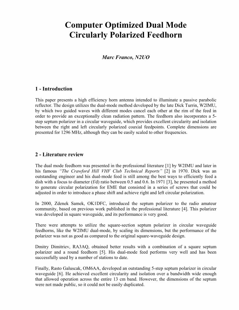
3 - Dual mode, circularly polarized feedhorn design I decided to make an attempt to fill the gap between the square septum polarizer and the W2IMU dual mode feedhorn by developing a 5-step septum polarizer in circular waveguide that could match the W2IMU feedhorn, achieving good performance in terms of isolation, circularity and bandwidth. I used HFSS [7], an electromagnetic simulation software that can also optimize dimensions based on specific goals, to design a 5-step septum polarizer. As a starting point, I took the dimensions of the 4-step septum that OK1DFC made popular, and added one more step for a maximum septum height of 184 mm, which is the diameter that OM6AA used for his circular 5-step septum. Once I obtained the dimensions for the septum by running an optimization, I designed a W2IMU feedhorn and re-optimized both pieces together again. The results obtained at this point were very good, but the feedhorn was much longer than a regular W2IMU, even with the screw polarizer. The isolation was good, but not outstanding. I suspected that most of the problems with the isolation were related to a mismatch between the polarizer and the feedhorn, so I decided to sweep the length of the polarizer’s waveguide to investigate the issue. Surprisingly, I noticed a marked change in isolation that repeated itself every half waveguide wavelength, as shown in Fig. 1. As a consequence, I decreased the length of the polarizer’s waveguide until I reached a maximum in isolation. I re-simulated the entire feed, and the results were excellent.
-50.00 0.00 50.00 100.00 150.00 200.00delta [mm]
-50.00
-45.00
-40.00
-35.00
-30.00
-25.00
-20.00
dB(S(WavePort1:1,WavePort2:1))
N2UO - Dual mode 5 step septum feed Isolation vs. TE11 waveguide lengthCurve Info
dB(S(WavePort1:1,WavePort2:1))Setup1 : LastAdaptive
Fig. 1 – Isolation between ports as a function of the length of the feed
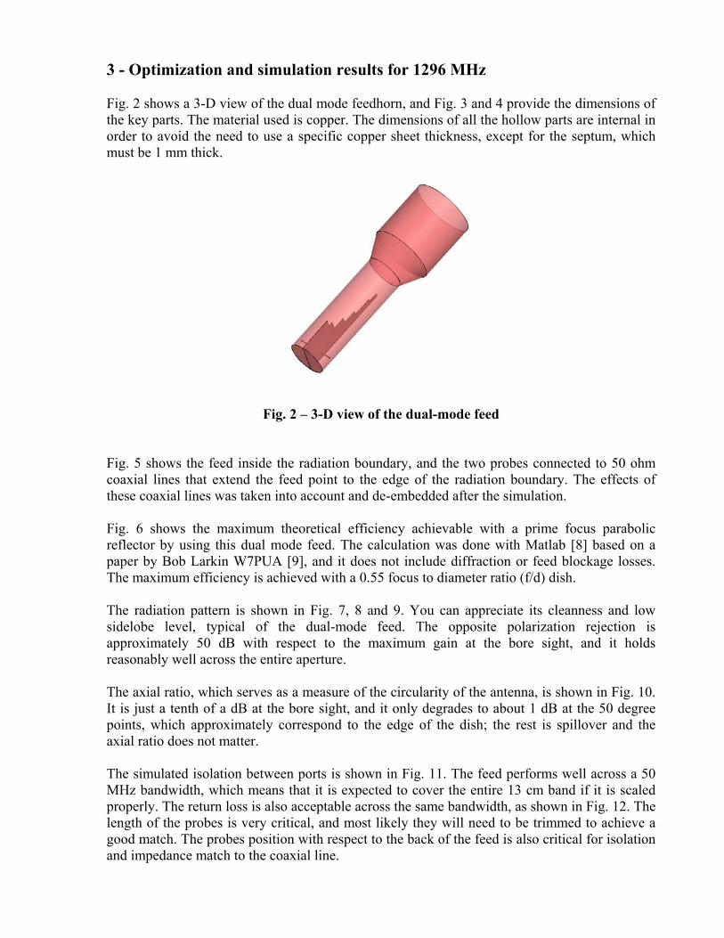
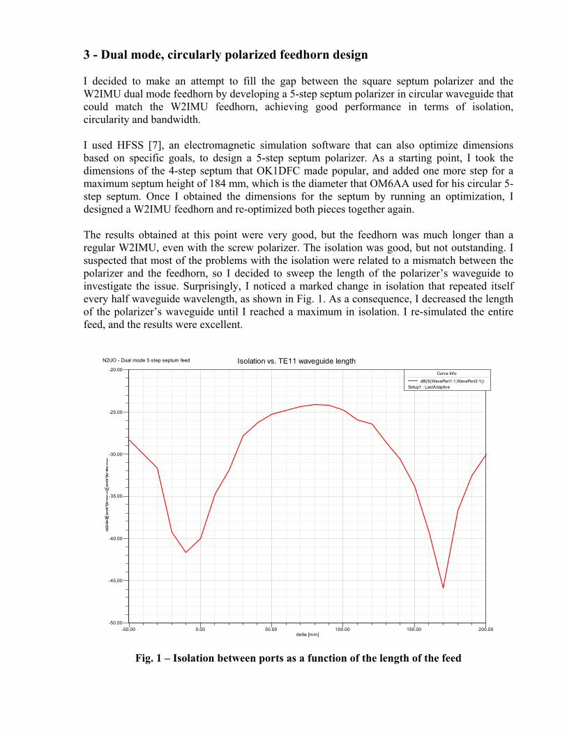
3 - Optimization and simulation results for 1296 MHz Fig. 2 shows a 3-D view of the dual mode feedhorn, and Fig. 3 and 4 provide the dimensions of the key parts. The material used is copper. The dimensions of all the hollow parts are internal in order to avoid the need to use a specific copper sheet thickness, except for the septum, which must be 1 mm thick.
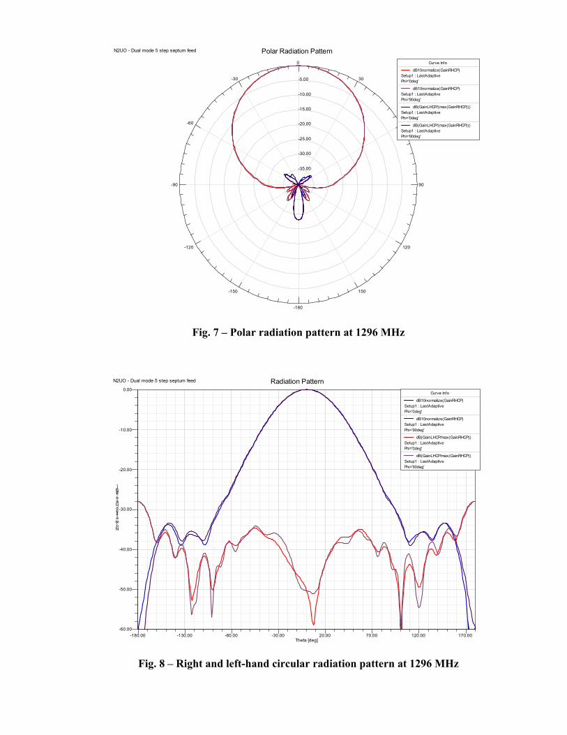
Fig. 2 – 3-D view of the dual-mode feed Fig. 5 shows the feed inside the radiation boundary, and the two probes connected to 50 ohm coaxial lines that extend the feed point to the edge of the radiation boundary. The effects of these coaxial lines was taken into account and de-embedded after the simulation. Fig. 6 shows the maximum theoretical efficiency achievable with a prime focus parabolic reflector by using this dual mode feed. The calculation was done with Matlab [8] based on a paper by Bob Larkin W7PUA [9], and it does not include diffraction or feed blockage losses. The maximum efficiency is achieved with a 0.55 focus to diameter ratio (f/d) dish. The radiation pattern is shown in Fig. 7, 8 and 9. You can appreciate its cleanness and low sidelobe level, typical of the dual-mode feed. The opposite polarization rejection is approximately 50 dB with respect to the maximum gain at the bore sight, and it holds reasonably well across the entire aperture. The axial ratio, which serves as a measure of the circularity of the antenna, is shown in Fig. 10. It is just a tenth of a dB at the bore sight, and it only degrades to about 1 dB at the 50 degree points, which approximately correspond to the edge of the dish; the rest is spillover and the axial ratio does not matter. The simulated isolation between ports is shown in Fig. 11. The feed performs well across a 50 MHz bandwidth, which means that it is expected to cover the entire 13 cm band if it is scaled properly. The return loss is also acceptable across the same bandwidth, as shown in Fig. 12. The length of the probes is very critical, and most likely they will need to be trimmed to achieve a good match. The probes position with respect to the back of the feed is also critical for isolation and impedance match to the coaxial line.
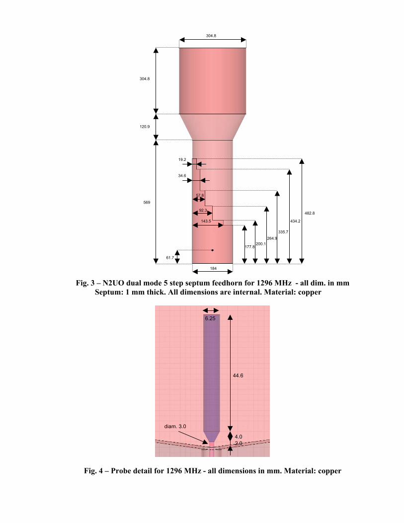
Fig. 3 – N2UO dual mode 5 step septum feedhorn for 1296 MHz - all dim. in mm
Septum: 1 mm thick. All dimensions are internal. Material: copper
Fig. 4 – Probe detail for 1296 MHz - all dimensions in mm. Material: copper
184
304.8
304.8
61.7
569
120.9
482.8
434.2
335.7 264.9
200.1177.8
19.2
34.6
57.8
92.3
143.5
6.25
44.6
4.0
diam. 3.0
2.0

Fig. 5 – Dual-mode feed inside the radiation boundary
with extended coaxial feedpoints
0.3 0.4 0.5 0.6 0.7 0.8 0.9 1 35
40
45
50
55
60
65
70
75
80
f/d ratio
Dish efficiency
[%]
Fig. 6 – Theoretical parabolic reflector efficiency
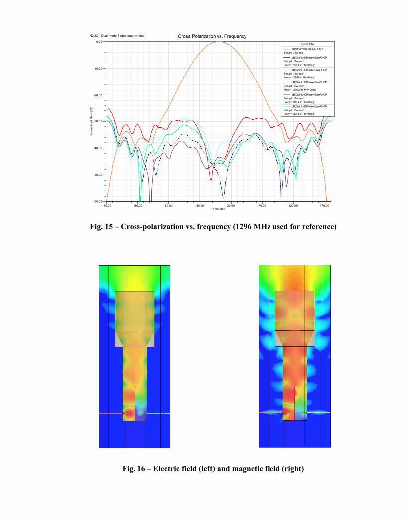
Fig. 13, 14 and 15 show the performance of the feed as a function of frequency. It can be seen that the axial ratio is approximately maintained below 2 dB across 100 MHz, and that the radiation pattern and the cross polarization do not suffer major degradations. Finally, Fig. 16 shows the electric and magnetic fields inside the feed. Careful inspection will reveal clear TE11 and TM11 mode patterns, which give name to this dual-mode feed.
-35.00
-30.00
-25.00
-20.00
-15.00
-10.00
-5.00
90
60
30
0
-30
-60
-90
-120
-150
-180
150
120
N2UO - Dual mode 5 step septum feed Polar Radiation PatternCurve Info
dB10normalize(GainRHCP)Setup1 : LastAdaptivePhi='0deg'
dB10normalize(GainRHCP)Setup1 : LastAdaptivePhi='90deg'
dB(GainLHCP/(max(GainRHCP)))Setup1 : LastAdaptivePhi='0deg'
dB(GainLHCP/(max(GainRHCP)))Setup1 : LastAdaptivePhi='90deg'
Fig. 7 – Polar radiation pattern at 1296 MHz
-180.00 -130.00 -80.00 -30.00 20.00 70.00 120.00 170.00Theta [deg]
-60.00
-50.00
-40.00
-30.00
-20.00
-10.00
0.00
Normalized Gain [dB]
N2UO - Dual mode 5 step septum feed Radiation PatternCurve Info
dB10normalize(GainRHCP)Setup1 : LastAdaptivePhi='0deg'
dB10normalize(GainRHCP)Setup1 : LastAdaptivePhi='90deg'
dB(GainLHCP/max(GainRHCP))Setup1 : LastAdaptivePhi='0deg'
dB(GainLHCP/max(GainRHCP))Setup1 : LastAdaptivePhi='90deg'
Fig. 8 – Right and left-hand circular radiation pattern at 1296 MHz
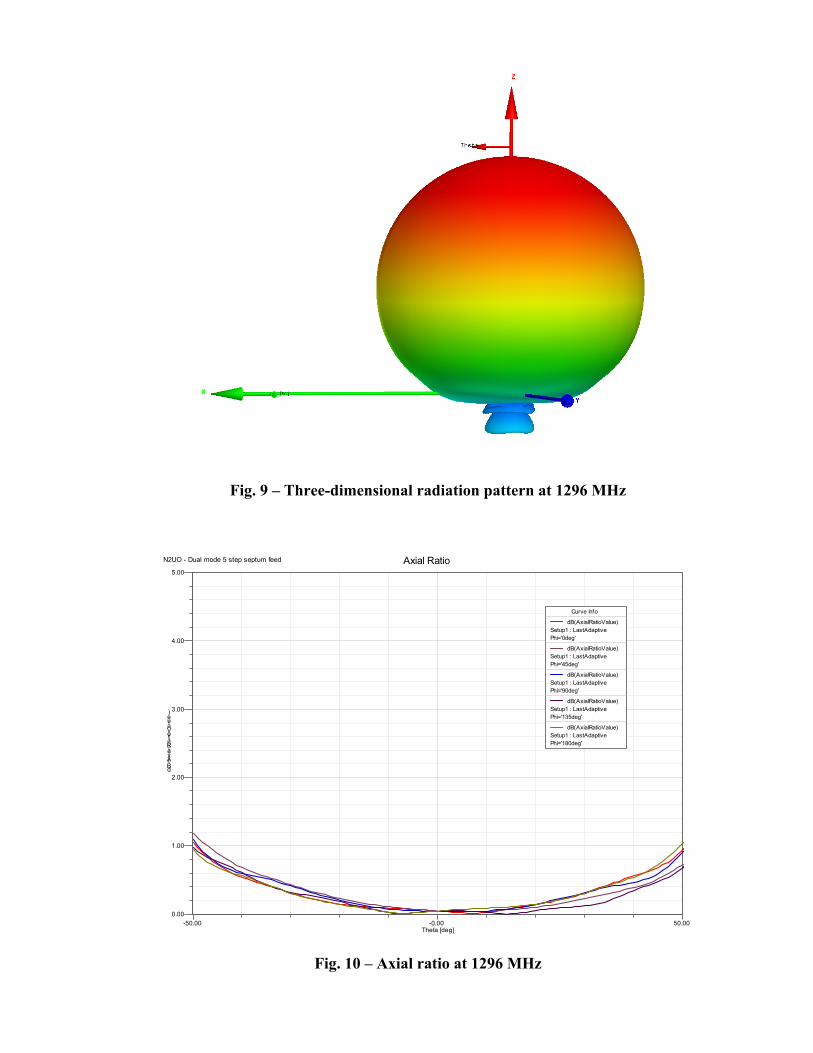
Fig. 9 – Three-dimensional radiation pattern at 1296 MHz
-50.00 -0.00 50.00Theta [deg]
0.00
1.00
2.00
3.00
4.00
5.00
dB(AxialRatioValue)
N2UO - Dual mode 5 step septum feed Axial Ratio
Curve Info
dB(AxialRatioValue)Setup1 : LastAdaptivePhi='0deg'
dB(AxialRatioValue)Setup1 : LastAdaptivePhi='45deg'
dB(AxialRatioValue)Setup1 : LastAdaptivePhi='90deg'
dB(AxialRatioValue)Setup1 : LastAdaptivePhi='135deg'
dB(AxialRatioValue)Setup1 : LastAdaptivePhi='180deg'
Fig. 10 – Axial ratio at 1296 MHz

1.27 1.28 1.29 1.30 1.31 1.32Freq [GHz]
-65.00
-60.00
-55.00
-50.00
-45.00
-40.00
-35.00
-30.00
dB(S
(Wav
ePor
t1:1
,Wav
ePor
t2:1
))
N2UO - Dual mode 5 step septum feed Isolation
m1
Curve Info
dB(S(WavePort1:1,WavePort2:1))Setup1 : Sw eep1
Name X Y
m1 1.2960 -47.6493
Fig. 11 – Isolation between ports
1.27 1.28 1.29 1.30 1.31 1.32Freq [GHz]
-40.00
-35.00
-30.00
-25.00
dB(S
(Wav
ePor
t1:1
,Wav
ePor
t1:1
))
N2UO - Dual mode 5 step septum feed Return Loss
m1
Curve Info
dB(S(WavePort1:1,WavePort1:1))Setup1 : Sw eep1
Name X Y
m1 1.2960 -38.4627
Fig. 12 – Return loss

-50.00 -25.00 0.00 25.00 50.00Theta [deg]
0.00
1.00
2.00
3.00
4.00
5.00
dB(A
xial
Rat
ioV
alue
)
N2UO - Dual mode 5 step septum feed Axial Ratio vs. Frequency
Curve Info
dB(AxialRatioValue)Setup1 : Sw eep1Freq='1.27GHz' Phi='0deg'
dB(AxialRatioValue)Setup1 : Sw eep1Freq='1.28GHz' Phi='0deg'
dB(AxialRatioValue)Setup1 : Sw eep1Freq='1.29GHz' Phi='0deg'
dB(AxialRatioValue)Setup1 : Sw eep1Freq='1.296GHz' Phi='0deg'
dB(AxialRatioValue)Setup1 : Sw eep1Freq='1.3GHz' Phi='0deg'
dB(AxialRatioValue)Setup1 : Sw eep1Freq='1.31GHz' Phi='0deg'
dB(AxialRatioValue)Setup1 : Sw eep1Freq='1.32GHz' Phi='0deg'
Fig. 13 – Axial ratio vs. frequency
-180.00 -130.00 -80.00 -30.00 20.00 70.00 120.00 170.00Theta [deg]
-60.00
-50.00
-40.00
-30.00
-20.00
-10.00
0.00
dB10
norm
aliz
e(G
ainR
HC
P)
N2UO - Dual mode 5 step septum feed Radiation Pattern vs. FrequencyCurve Info
dB10normalize(GainRHCP)Setup1 : Sw eep1Freq='1.27GHz' Phi='0deg'
dB10normalize(GainRHCP)Setup1 : Sw eep1Freq='1.28GHz' Phi='0deg'
dB10normalize(GainRHCP)Setup1 : Sw eep1Freq='1.296GHz' Phi='0deg'
dB10normalize(GainRHCP)Setup1 : Sw eep1Freq='1.31GHz' Phi='0deg'
dB10normalize(GainRHCP)Setup1 : Sw eep1Freq='1.32GHz' Phi='0deg'
Fig. 14 – Right hand circular radiation pattern vs. frequency
-180.00 -130.00 -80.00 -30.00 20.00 70.00 120.00 170.00Theta [deg]
-60.00
-50.00
-40.00
-30.00
-20.00
-10.00
0.00
Nor
mal
ized
Gai
n [d
B]
N2UO - Dual mode 5 step septum feed Cross Polarization vs. FrequencyCurve Info
dB10normalize(GainRHCP)Setup1 : Sw eep1
dB(GainLHCP/max(GainRHCP))Setup1 : Sw eep1Freq='1.27GHz' Phi='0deg'
dB(GainLHCP/max(GainRHCP))Setup1 : Sw eep1Freq='1.28GHz' Phi='0deg'
dB(GainLHCP/max(GainRHCP))Setup1 : Sw eep1Freq='1.296GHz' Phi='0deg'
dB(GainLHCP/max(GainRHCP))Setup1 : Sw eep1Freq='1.31GHz' Phi='0deg'
dB(GainLHCP/max(GainRHCP))Setup1 : Sw eep1Freq='1.32GHz' Phi='0deg'
Fig. 15 – Cross-polarization vs. frequency (1296 MHz used for reference)
Fig. 16 – Electric field (left) and magnetic field (right)
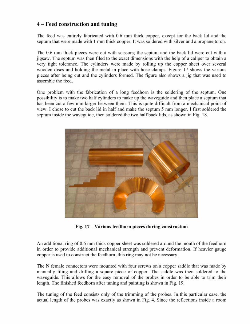
4 – Feed construction and tuning The feed was entirely fabricated with 0.6 mm thick copper, except for the back lid and the septum that were made with 1 mm thick copper. It was soldered with silver and a propane torch. The 0.6 mm thick pieces were cut with scissors; the septum and the back lid were cut with a jigsaw. The septum was then filed to the exact dimensions with the help of a caliper to obtain a very tight tolerance. The cylinders were made by rolling up the copper sheet over several wooden discs and holding the metal in place with hose clamps. Figure 17 shows the various pieces after being cut and the cylinders formed. The figure also shows a jig that was used to assemble the feed. One problem with the fabrication of a long feedhorn is the soldering of the septum. One possibility is to make two half cylinders to make up the waveguide and then place a septum that has been cut a few mm larger between them. This is quite difficult from a mechanical point of view. I chose to cut the back lid in half and make the septum 5 mm longer. I first soldered the septum inside the waveguide, then soldered the two half back lids, as shown in Fig. 18.
Fig. 17 – Various feedhorn pieces during construction
An additional ring of 0.6 mm thick copper sheet was soldered around the mouth of the feedhorn in order to provide additional mechanical strength and prevent deformation. If heavier gauge copper is used to construct the feedhorn, this ring may not be necessary. The N female connectors were mounted with four screws on a copper saddle that was made by manually filing and drilling a square piece of copper. The saddle was then soldered to the waveguide. This allows for the easy removal of the probes in order to be able to trim their length. The finished feedhorn after tuning and painting is shown in Fig. 19. The tuning of the feed consists only of the trimming of the probes. In this particular case, the actual length of the probes was exactly as shown in Fig. 4. Since the reflections inside a room

disrupt the measurements, it is recommended to perform the tuning outdoors or place the feedhorn looking through an open window with all obstructions far away. This provision is particularly important at the time of measuring the isolation.
Fig. 18 – Detail of the back lid and septum
Fig. 19 – View of the feedhorn after tuning and painting

5 – Measurements results As mentioned before, the feed was placed with the mouth looking through a window with all obstructions far enough to avoid reflections during the measurements. The test equipment used was an HP141T spectrum analyzer, a home made tracking generator, a directional coupler, a signal source, an HP435A power meter, and a linearly polarized feedhorn made with two large coffee cans. Fig. 20 shows the return loss measurement. The directivity of the directional coupler limited the measurement to 30 dB; however, the return loss degrades to 25 dB across 50 MHz of bandwidth in good agreement with the simulation results, and it is quite probable that the actual return loss at 1296 MHz is in the vicinity of 35 dB, as predicted by the simulations.
Fig. 20 – Feedhorn return loss Vertical scale: 10 dB/DIV
Horizontal scale: 5 MHz/DIV, centered at 1296 MHz
The port to port isolation measurements are shown in Fig. 21 and 22 across 100 and 50 MHz, respectively. The agreement with the simulated results is quite good, although the deep notch shown in the simulation does not appear in reality. It is important to mention that once the feedhorn is placed at the focal point of a prime focus dish, the reflections from the center of the dish as well as other objects in the vicinity (e.g., feedhorn support) will degrade the port to port isolation, so a preamplifier protection relay is a must. The circularity was measured by attaching the signal source to the feedhorn and rotating the linear feed placed in front of it 360 degrees and noticing the change in received signal. The largest difference recorded was 0.7 dB, indicating very good circularity.
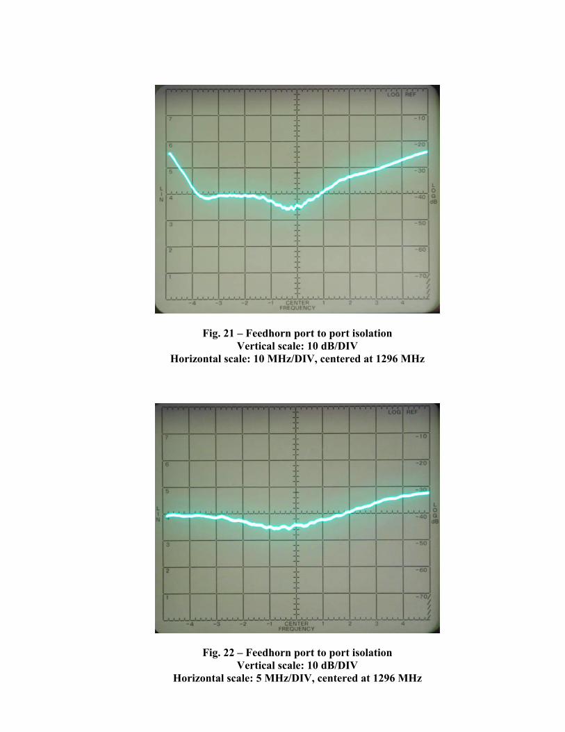
Fig. 21 – Feedhorn port to port isolation Vertical scale: 10 dB/DIV
Horizontal scale: 10 MHz/DIV, centered at 1296 MHz
Fig. 22 – Feedhorn port to port isolation Vertical scale: 10 dB/DIV
Horizontal scale: 5 MHz/DIV, centered at 1296 MHz

6 - Conclusion This dual mode feedhorn with a 5-step septum polarizer offers a very clean radiation pattern, high efficiency optimized for a prime focus parabolic reflector with an f/d of 0.55, and excellent circularity and isolation between ports. The septum dimensions, as well as the probe position, are very critical. The probe length should be trimmed to achieve resonance at the operating frequency, but the value of the feed impedance is mostly determined by the probe position with respect to the back of the feed. Simulations of other types of feeds intended for deeper dishes (smaller f/d) did not yield the same type of results in terms of spillover, circularity and isolation between ports. It is quite possible that this feed will still be a good choice for deeper dishes in spite of the slightly lower efficiency, which could be compensated by its remarkably clean pattern, and as a consequence, a lower antenna noise temperature. 7 - Acknowledgment I would like to thank Bob Kaltenecker and Paul Wade, W1GHZ, for their help with HFSS, and Eddy Jespers, ON7UN, Walter Crauwels, ON4BCB, and Dan Habecker, W9EQ, for the interesting discussions during the development of this antenna. 8 - References [1] – Turrin, R., “Dual Mode Small-Aperture Antennas”, IEEE Transactions on Antennas and Propagation, March 1967. [2] - Dick Turrin, “Technical Report #5”, The Crawford Hill VHF Club, W2NFA, 1970. [3] - Dick Turrin, “Technical Report #9”, The Crawford Hill VHF Club, W2NFA, 1971. [4] – M. Chen, G. Tsandoulas, “A Wide-Band Square-Waveguide Array Polarizer”, IEEE Transactions on Antennas and Propagation, May 1973. [5] - http://www.ok1dfc.com/eme/technic/septum/ra3aq.pdf [6] - http://www.attplus.cz/hamradio/projekty/article/Septum_feed_EUCAP2006.pdf [7] - http://ansoft.com/products/hf/hfss/ [8] - http://www.mathworks.com/ [9] - Bob Larkin, W7PUA, “Dipole-Reflector Parabolic Dish Feeds for F/D of 0.24 to 0.4”, QEX, February 1996.