computational studies of collective beam dynamics in high
TRANSCRIPT
COMPUTATIONAL STUDIES OF COLLECTIVE BEAM DYNAMICS IN HIGH INTENSITY RINGS
J.A. Holmes, S. Cousineau, V. Danilov, S. Henderson, A. Shishlo, ORNL, Oak Ridge, TN 37831, USA
A. Fedotov, BNL, Upton, NY 11793, USA
Abstract Collective interactions of the beam with itself and with
its periodic lattice surroundings in high intensity accelerator rings, such as PSR and SNS, can lead to beam growth, halo generation, and losses. These interactions also provide a rich source of dynamic phenomena for analytical, computational, and experimental study. With continuing increases in model development and computer power, a number of sophisticated codes are now capable of detailed realistic studies of collective beam dynamics in rings. We concentrate here on a computational examination of high intensity beam dynamics in SNS. These studies include the effects of the accelerator lattice, space charge, impedances, losses and collimation, and magnet errors.
OVERVIEW High-intensity proton rings are characterized by low
energy, high intensity beams, and by low loss requirements. Collective effects due to space charge and wakefields strongly affect the beam behavior, and single particle models do not suffice. Because of the complexity of collective phenomena for bunched beams in high-intensity rings, a computational approach is productive for theoretical studies and indispensable in solving detailed design and engineering problems. Recognizing this, accelerator physicists from ORNL, BNL, and Fermilab have been developing an object-oriented general-purpose code, ORBIT [1,2].
ORBIT is designed specifically for beam dynamics calculations in high-intensity rings. Its intended use is the detailed simulation of realistic accelerator problems, although it is equally applicable to idealized situations. ORBIT is a particle-in-cell tracking code in 6D phase space that transports bunches of interacting particles through a series of nodes representing elements, dynamic effects, or diagnostics that occur in the accelerator. ORBIT has been designed to simulate real machines: it has detailed models for strip-foil injection including painting, scattering, and nuclear processes; RF focusing and acceleration; symplectic transport through various magnetic elements with optional hard-edge fringe fields; alignment and field errors, closed obit calculation, and error correction; longitudinal and transverse impedances; longitudinal, transverse, and three-dimensional space charge forces; feedback stabilization of instabilities; beam-in-gap cleaning, collimation, and limiting apertures; and the calculation of many useful diagnostic quantities.
ORBIT has been applied to a variety of problems in high intensity rings. These include investigations in basic ring physics, diverse applications to the design and
analysis of the SNS ring, analysis of emittance measurements in the CIS at Indiana University, extensive studies of the dynamics behind the beam broadening at high intensity in PSR at Los Alamos National Laboratory, and simulation of space charge effects at injection in the Fermilab Proton Driver Study II. Because of the understanding of PSR beam broadening gained using ORBIT, correction of the driving n=4 lattice harmonic is currently under study. Some of these applications are described in Refs. [3-8]. More recently, ORBIT is being applied to study space charge effects during injection into the Fermilab Booster Ring. This work is of importance because the Booster is the intensity bottleneck in the Fermilab accelerators, and because a significant fraction of the losses in the Booster occur during the first three milliseconds.
In addition to the PSR harmonic correction and Fermilab Booster calculations, present applications of ORBIT focus on the use of the new and computationally demanding physics models to study and reoptimize as realistically as possible injection scenarios in the SNS Ring. The product of these studies will be a total foil to target simulation picture of the injection, accumulation, and ring to target transport processes. This simulation picture will actually consist of a whole series of calculations to differentiate and understand the effects of foil scattering, single particle transport, fringe fields, errors and error correction, space charge, impedances, and collimation. Ultimately, the goal is to optimize the injection with respect to losses and beam-on-target, which requires varying the painting scheme, lattice tunes, chromaticities, and collimation scraper settings. We now present initial results of this study.
SNS FOIL TO TARGET SIMULATIONS To begin the SNS foil to target studies, we consider the
SNS lattice with the nominal bare tunes (Qx, Qy) = (6.23, 6.20), no chromaticity correction, and 1.44 MW beam power, which corresponds to a final bunch of 1.5*1014 protons. The calculations include the effects of the strip foil and painting, symplectic single particle transport with hard edge fringe fields, dual harmonic RF focusing, longitudinal and transverse impedances, space charge, apertures and collimation, and magnet errors and correction. The first task was to determine the computational requirements imposed by convergence of the space charge model. For the SNS Ring, with bunch length in excess of 160m and slow variation in longitudinal density, the 2.5D transverse and separate longitudinal space charge model are sufficiently accurate unless transverse impedance effects become important. The space charge convergence tests were conducted with
0-7803-7739-9 ©2003 IEEE 117
Proceedings of the 2003 Particle Accelerator Conference
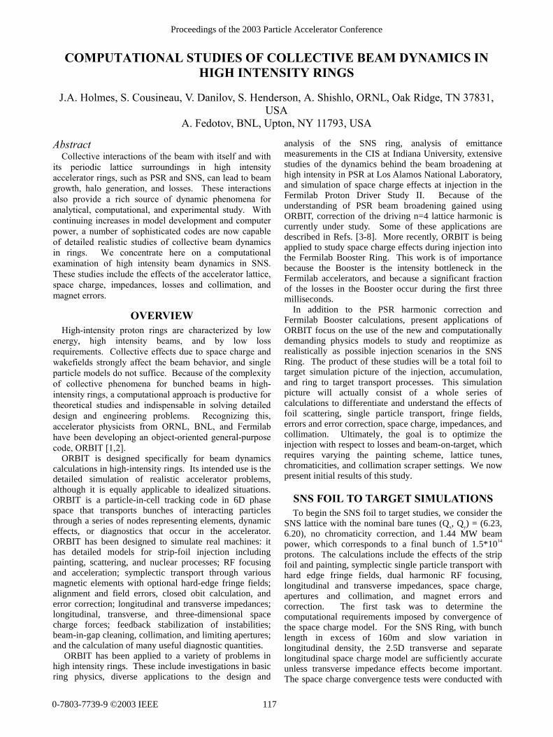
the transverse impedance set to zero. For ORBIT’s three space charge models, the grid resolution and the number of particles were varied until convergence was achieved. The resulting grid sizes and numbers of particles were 64x64 mesh and 159000 particles for the 2.5D direct force space charge solver, 256x256 mesh and 530000 particles for the 2.5D potential space charge solver, and 256x256x64 mesh and 1590000 particles for the 3D solver. The difference in requirements between the 2.5D direct force and potential solvers is a result of the necessity of taking a derivative to obtain the force when the potential solver is used. Figure 1 shows the horizontal emittance profiles of the final accumulated beam at the 1*10-3 level for the converged cases of the three space charge models, and it is clear that unless the transverse impedance generates instabilities that necessitate a 3D treatment, either of the 2.5D models is adequate.
0
0.02
0.04
0.06
0.08
0.1
0 50 100 150 200 250
Per
cent
of B
eam
Exc
eedi
ng E
mitt
ance
Horizontal Emittance [mm-mrad]
Horizontal Emittance Profiles at the Edge of Accumulated Beam
2D Direct Force Space Charge Model2D Potential Space Charge Model3D Potential Space Charge Model
Figure 1. Percentage of beam with emittance exceeding the value indicated for the 2.5D direct force solver (red) with 159000 particles, the 2.5D potential solver (green) with 530000 particles, and the 3D solver (blue) with 1590000 particles.
In order to determine if the 3D space charge treatment
is necessary, the transverse impedance was set to that of the ring extraction kicker, which is the dominant impedance in the ring, and a 3D space charge calculation was conducted. The results indicated transverse stability at 1.44 MW (the instability threshold is at about 2 MW), so the 2.5D direct force transverse space charge model is suitable for these studies.
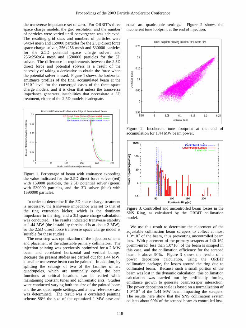
The next step was optimization of the injection scheme and placement of the adjustable primary collimators. The injection painting was previously optimized for a 2 MW beam and correlated horizontal and vertical bumps. Because the present studies are carried out for 1.44 MW, a smaller transverse beam can be painted. In addition, by splitting the settings of two of the families of arc quadrupoles, which are nominally equal, the beta functions at critical locations can be varied while maintaining constant tunes and achromatic arcs. Studies were conducted varying both the size of the painted beam and the arc quadrupole settings, and a new reference case was determined. The result was a correlated painting scheme 86% the size of the optimized 2 MW case and
equal arc quadrupole settings. Figure 2 shows the incoherent tune footprint at the end of injection.
5.95
6
6.05
6.1
6.15
6.2
6.25
5.95 6 6.05 6.1 6.15 6.2 6.25
Ve
rtic
al T
un
e
Horizontal Tune
Tune Footprint Following Injection, 86% Beam Size
Figure 2. Incoherent tune footprint at the end of accumulation for 1.44 MW beam power.
0.1
1
10
100
1000
50 100 150 200
Pow
er D
epos
ition
[Wat
ts/m
]
Position in Ring [m]
Controlled LossesUncontrolled Losses
1 Watts/m
0.1
1
10
100
1000
50 100 150 200
Pow
er D
epos
ition
[Wat
ts/m
]
Position in Ring [m]
Controlled LossesUncontrolled Losses
Figure 3. Controlled and uncontrolled beam losses in the SNS Ring, as calculated by the ORBIT collimation model.
We use this result to determine the placement of the
adjustable collimation beam scrapers to collect at most 1.0*10-3 of the beam, thus preventing uncontrolled beam loss. With placement of the primary scrapers at 140-162 pi-mm-mrad, less than 1.0*10-4 of the beam is scraped in this case, and the collimation efficiency for the scraped beam is above 90%. Figure 3 shows the results of a power deposition calculation, using the ORBIT collimation package, for losses around the ring due to collimated beam. Because such a small portion of the beam was lost in the dynamic calculation, this collimation calculation was carried out by artificially forcing emittance growth to generate beam/scraper interaction. The power deposition scale is based on a normalization of 1.0*10-3 of the 1.44 MW beam impacting the scrapers. The results here show that the SNS collimation system collects about 90% of the scraped beam as controlled loss.
118
Proceedings of the 2003 Particle Accelerator Conference
Another important consideration is the beam footprint on the target. Engineering considerations require at least 90% of the beam to land in a 20cm x 7cm rectangle on the target face with a maximum current density not exceeding 250mA/mm2. We use ORBIT to transport the final accumulated beam through the Ring to Target Beam Transport line and through the target window, modeled as a solid 4mm steel collimator, and finally to the target. Figure 4 shows a contour plot of the beam current on target as calculated by ORBIT. For this case, 91% of the accumulated beam falls into the 20cm x 7 cm rectangle and the peak beam current is 179mA/mm2.
Beam Current on Target [mA/m^2]
160 140 120 100 80 60 40 20
-40
-20
0
20
40
y [mm]
-100 -50 0 50 100x [mm]
Figure 4. Beam current on target as calculated by ORBIT.
We are now extending this initial work to include a
comprehensive study of alignment and field errors in bends and quadrupoles. In the first of these studies, we considered the effect of uniformly distributed random quadrupole alignment errors. At the anticipated level of ±0.25 mm random errors, beam losses remain below 1*10-4, but at twice that level beam losses increase rapidly. For the case of ±1.0 mm randomly distributed quadrupole alignment errors, 56% of the beam was lost during injection. After correcting these errors using the ORBIT error correction model on a pencil beam to set the dipole corrector strengths, the losses for injection again fell back to less than 1*10-4.
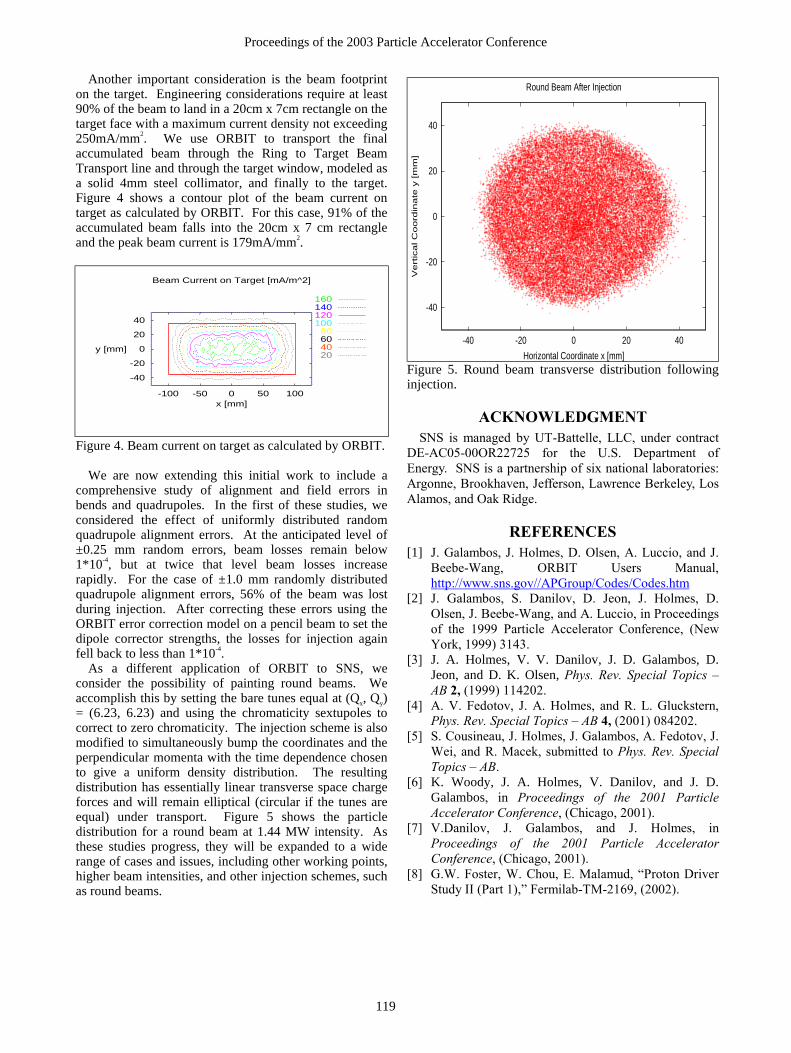
As a different application of ORBIT to SNS, we consider the possibility of painting round beams. We accomplish this by setting the bare tunes equal at (Qx, Qy) = (6.23, 6.23) and using the chromaticity sextupoles to correct to zero chromaticity. The injection scheme is also modified to simultaneously bump the coordinates and the perpendicular momenta with the time dependence chosen to give a uniform density distribution. The resulting distribution has essentially linear transverse space charge forces and will remain elliptical (circular if the tunes are equal) under transport. Figure 5 shows the particle distribution for a round beam at 1.44 MW intensity. As these studies progress, they will be expanded to a wide range of cases and issues, including other working points, higher beam intensities, and other injection schemes, such as round beams.
-40
-20
0
20
40
-40 -20 0 20 40
Vert
ical C
oord
inate
y [m
m]
Horizontal Coordinate x [mm]
Round Beam After Injection
Figure 5. Round beam transverse distribution following injection.
ACKNOWLEDGMENT SNS is managed by UT-Battelle, LLC, under contract
DE-AC05-00OR22725 for the U.S. Department of Energy. SNS is a partnership of six national laboratories: Argonne, Brookhaven, Jefferson, Lawrence Berkeley, Los Alamos, and Oak Ridge.
REFERENCES [1] J. Galambos, J. Holmes, D. Olsen, A. Luccio, and J.
Beebe-Wang, ORBIT Users Manual, http://www.sns.gov//APGroup/Codes/Codes.htm
[2] J. Galambos, S. Danilov, D. Jeon, J. Holmes, D. Olsen, J. Beebe-Wang, and A. Luccio, in Proceedings of the 1999 Particle Accelerator Conference, (New York, 1999) 3143.
[3] J. A. Holmes, V. V. Danilov, J. D. Galambos, D. Jeon, and D. K. Olsen, Phys. Rev. Special Topics � AB 2, (1999) 114202.
[4] A. V. Fedotov, J. A. Holmes, and R. L. Gluckstern, Phys. Rev. Special Topics � AB 4, (2001) 084202.
[5] S. Cousineau, J. Holmes, J. Galambos, A. Fedotov, J. Wei, and R. Macek, submitted to Phys. Rev. Special Topics � AB.
[6] K. Woody, J. A. Holmes, V. Danilov, and J. D. Galambos, in Proceedings of the 2001 Particle Accelerator Conference, (Chicago, 2001).
[7] V.Danilov, J. Galambos, and J. Holmes, in Proceedings of the 2001 Particle Accelerator Conference, (Chicago, 2001).
[8] G.W. Foster, W. Chou, E. Malamud, �Proton Driver Study II (Part 1),� Fermilab-TM-2169, (2002).
119
Proceedings of the 2003 Particle Accelerator Conference